Embed Size (px)
Citation preview

Status of PNPI R&D for choice of the MUCH tracking base detector
(this work is supported by INTAS)
■ Introduction
■ MICROMEGAS
■ GEM
■ MICROMEGAS+GEM
■ Future plans
Introduction
CBM requirements :
● rate up to 107 1/cm2∙s events
• in time <100 ns detector should be ready for next event
• high occupancy – thin granularity (especially in central region)
● not too high spatial resolution – σ~500μ
● low discharge probability
● radiation resistance
As candidates to fulfill CBM requirements are considered MM/GEM base tracking detectors. Both types of detectors are working well in real experiments.
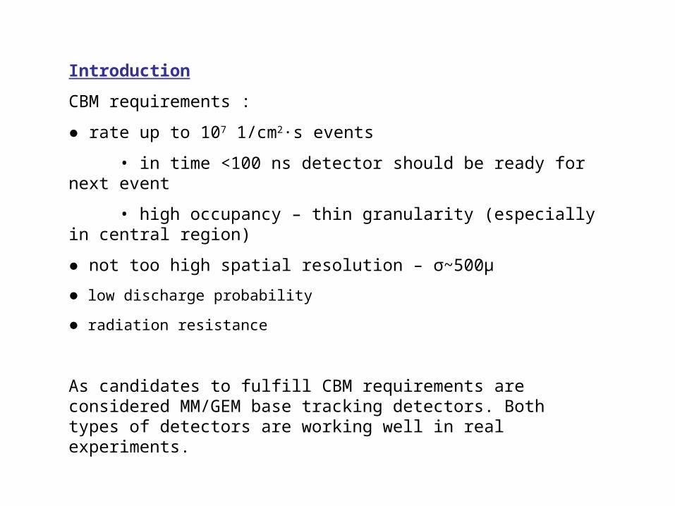
Main goals of R&D:
- getting some experience in working with MM/GEM
- finding practical technological solutions and requirements in building the detectors based on MM/GEM
- choosing the working gas
- estimating the descharge probability
- estimating the efficiency
- estimating the radiation rigidity
- getting a competence for designing the prototypes for beam test
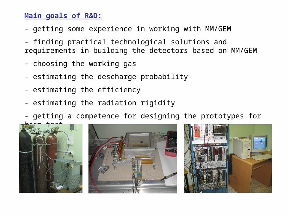
MICROMEGAS
75μ
3 mm
cathode
mesh
Pillars made by chemical etching from photo-resistant layer
4mm between pillars, diameter of each pillar - 300μ, height - 75μ
PCB (5x5 cm2)
PA
First steps in MICROMEGAS study were made for 200μ and 100μ mesh-PCB gap. There was not pillars and mesh before gluing to the frame was strained. Results of that were shown at last CBM workshop.
Main reason to move to the gap of 75μ was time width of the signal - full width was ~650 ns for 200μ gap and ~300 ns for 100μ (in Ar/CO2 gas mixture), and have working regime at lower HV (lower energy in discharge).
Following work was made with gap of 75μ.
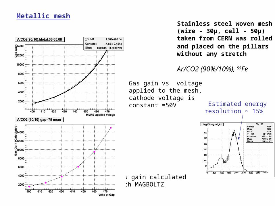
Metallic meshStainless steel woven mesh (wire - 30μ, cell - 50μ) taken from CERN was rolled and placed on the pillars without any stretch
Ar/CO2 (90%/10%), 55Fe
Gas gain calculated with MAGBOLTZ
Gas gain vs. voltage applied to the mesh, cathode voltage is constant =50V
Estimated energy resolution ~ 15%

Combined metallic-plastic mesh
Gas gain vs. cathode voltage,
mesh voltage is constant =500V
Gas gain vs. mesh voltage,
cathode voltage is constant =1000 V
Example of the spectrum (Fe55 )
Ar/CO2 (90%/10%) Woven mesh (stainless steel/nylon wire – 30 μ, cell - 50 μ) taken from CERN did not have any stretch
Energy resolution ~18%
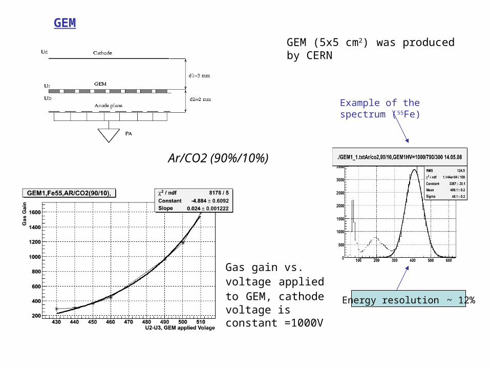
Ar/CO2 (90%/10%)
GEM (5x5 cm2) was produced by CERN
GEM
Gas gain vs. voltage applied to GEM, cathode voltage is constant =1000V
Example of the spectrum (55Fe)
Energy resolution ~ 12%
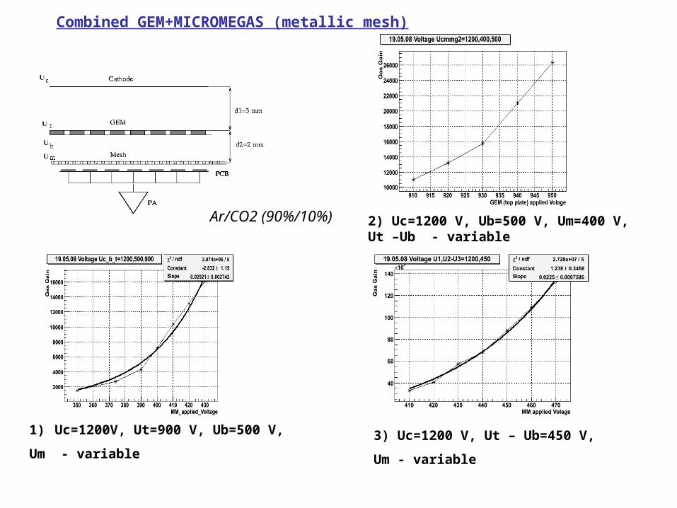
Combined GEM+MICROMEGAS (metallic mesh)
1) Uc=1200V, Ut=900 V, Ub=500 V,
Um - variable
2) Uc=1200 V, Ub=500 V, Um=400 V, Ut –Ub - variable
3) Uc=1200 V, Ut – Ub=450 V,
Um - variable
Ar/CO2 (90%/10%)
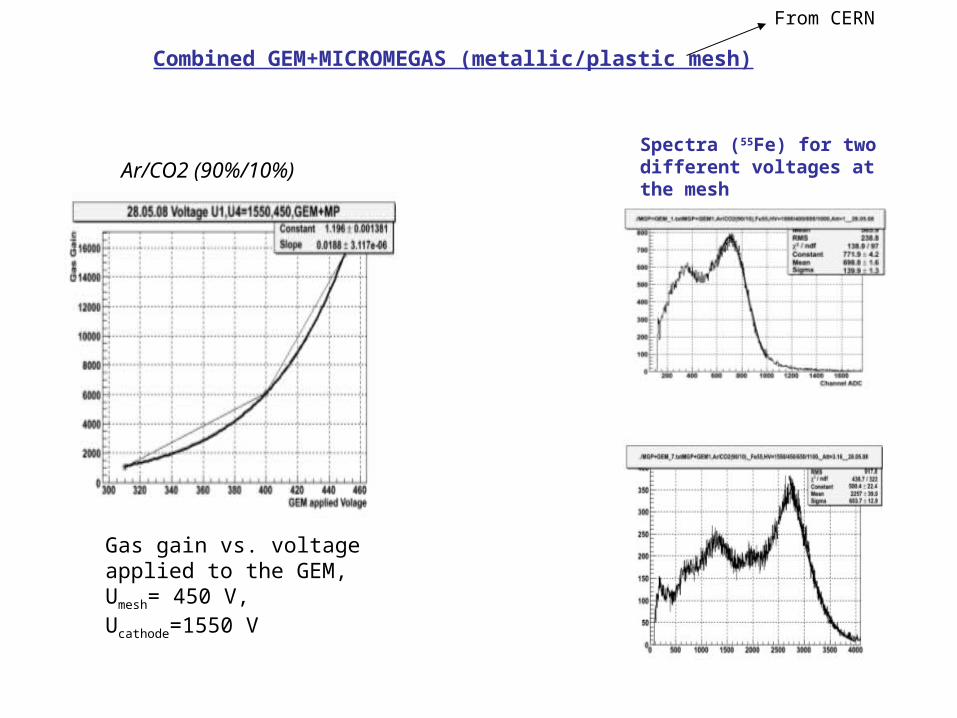
Combined GEM+MICROMEGAS (metallic/plastic mesh)
Spectra (55Fe) for two different voltages at the mesh
From CERN
Ar/CO2 (90%/10%)
Gas gain vs. voltage applied to the GEM, Umesh= 450 V, Ucathode=1550 V
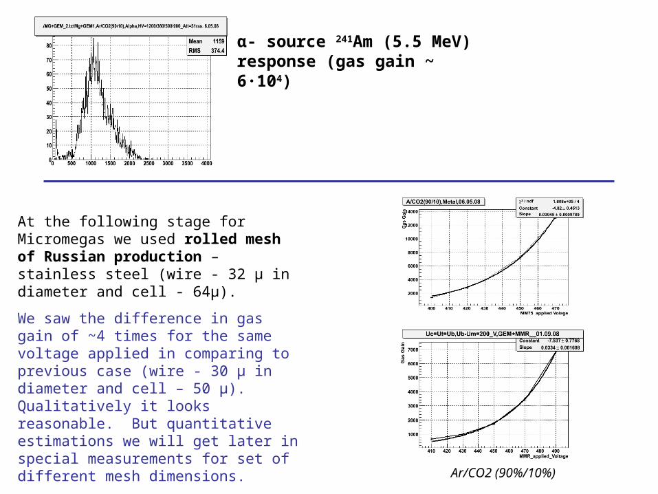
α- source 241Am (5.5 MeV) response (gas gain ~ 6∙104)
At the following stage for Micromegas we used rolled mesh of Russian production – stainless steel (wire - 32 μ in diameter and cell - 64μ).
We saw the difference in gas gain of ~4 times for the same voltage applied in comparing to previous case (wire - 30 μ in diameter and cell – 50 μ). Qualitatively it looks reasonable. But quantitative estimations we will get later in special measurements for set of different mesh dimensions.
Ar/CO2 (90%/10%)
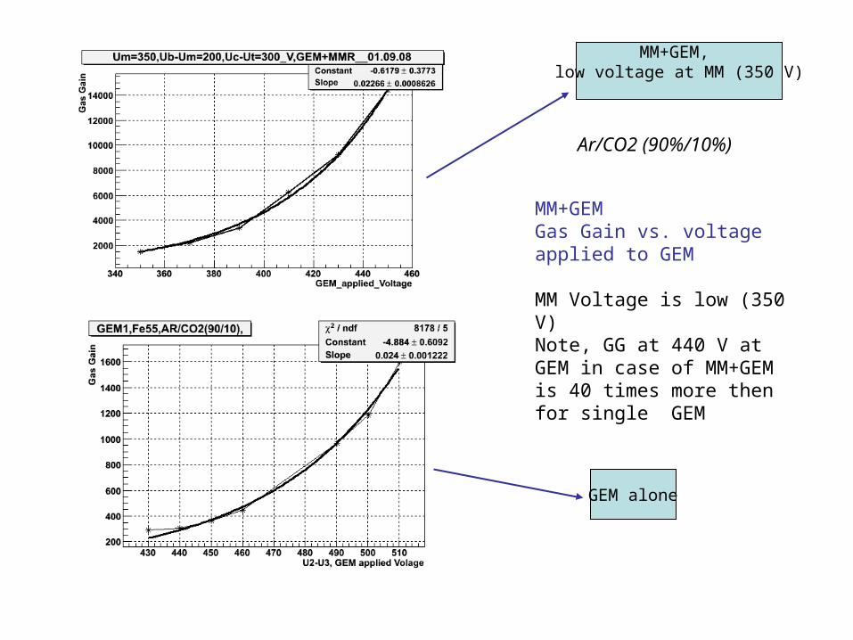
MM+GEM, low voltage at MM (350 V)
GEM alone
MM+GEMGas Gain vs. voltage applied to GEM
MM Voltage is low (350 V)Note, GG at 440 V at GEM in case of MM+GEM is 40 times more then for single GEM
Ar/CO2 (90%/10%)
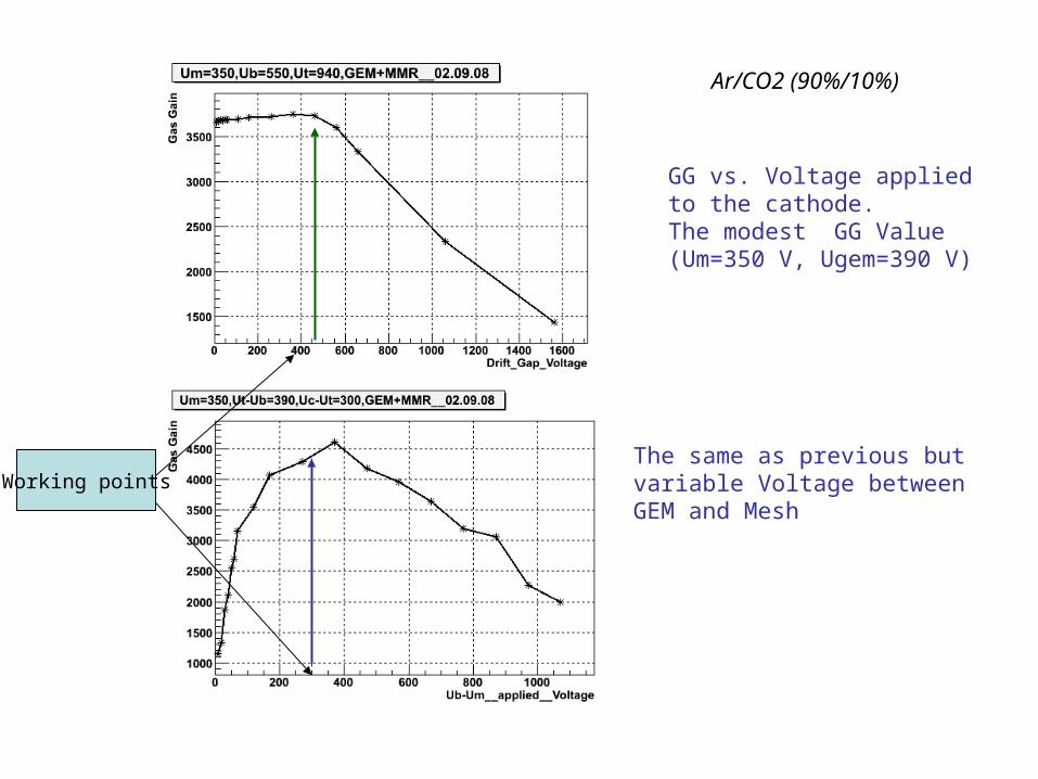
GG vs. Voltage applied to the cathode.The modest GG Value (Um=350 V, Ugem=390 V)
The same as previous butvariable Voltage betweenGEM and Mesh
Working points
Ar/CO2 (90%/10%)
He/CO2 (90%/10%) gas mixture

Comparison between Ar/CO2 and He/CO2
Signals (55Fe) measured by the scope
Full width (Ar/CO2) ~ 180 ns
Full width (He/CO2) ~ 100 ns
Changing distance between GEM and MICROMEGAS
to 1-1.5 mm and using HE/CF4 should decrease the collecting time to ~ 50 ns

Comparison between Ar/CO2 and He/CO2
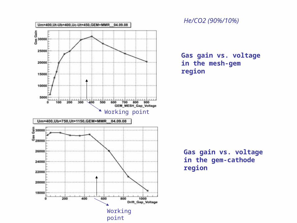
He/CO2 (90%/10%)
Gas gain vs. voltage in the mesh-gem region
Gas gain vs. voltage in the gem-cathode region
Working point
Working point
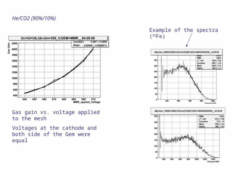
He/CO2 (90%/10%)
Example of the spectra (55Fe)
Gas gain vs. voltage applied to the mesh
Voltages at the cathode and both side of the Gem were equal
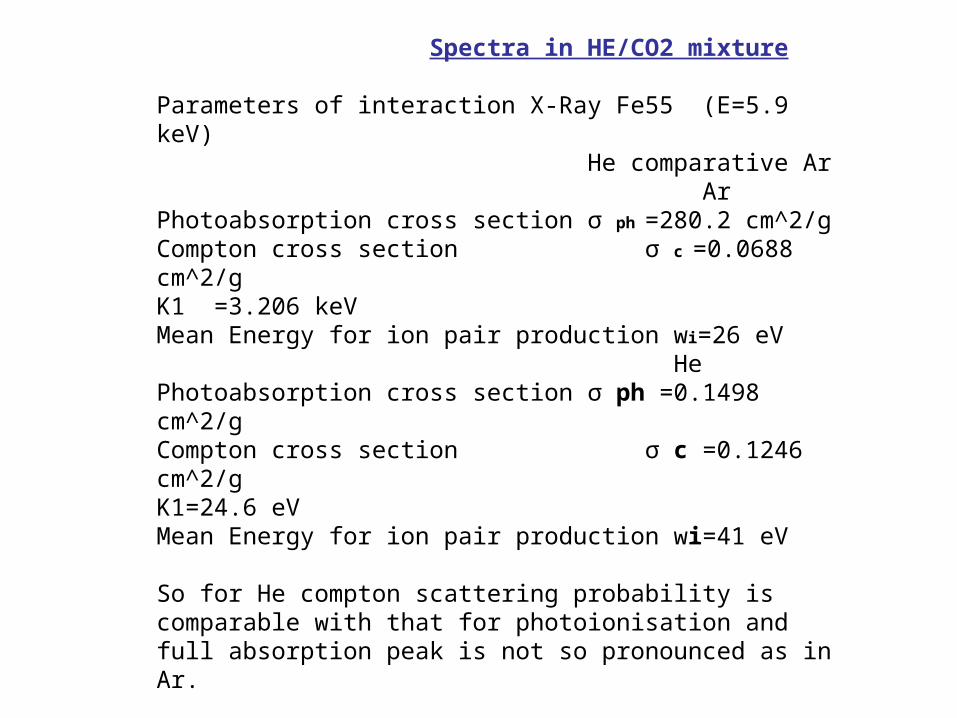
Spectra in HE/CO2 mixture
Parameters of interaction X-Ray Fe55 (E=5.9 keV) He comparative Ar ArPhotoabsorption cross section σ ph =280.2 cm^2/gCompton cross section σ c =0.0688 cm^2/gK1 =3.206 keVMean Energy for ion pair production wi=26 eV HePhotoabsorption cross section σ ph =0.1498 cm^2/gCompton cross section σ c =0.1246 cm^2/gK1=24.6 eVMean Energy for ion pair production wi=41 eV
So for He compton scattering probability is comparable with that for photoionisation and full absorption peak is not so pronounced as in Ar.
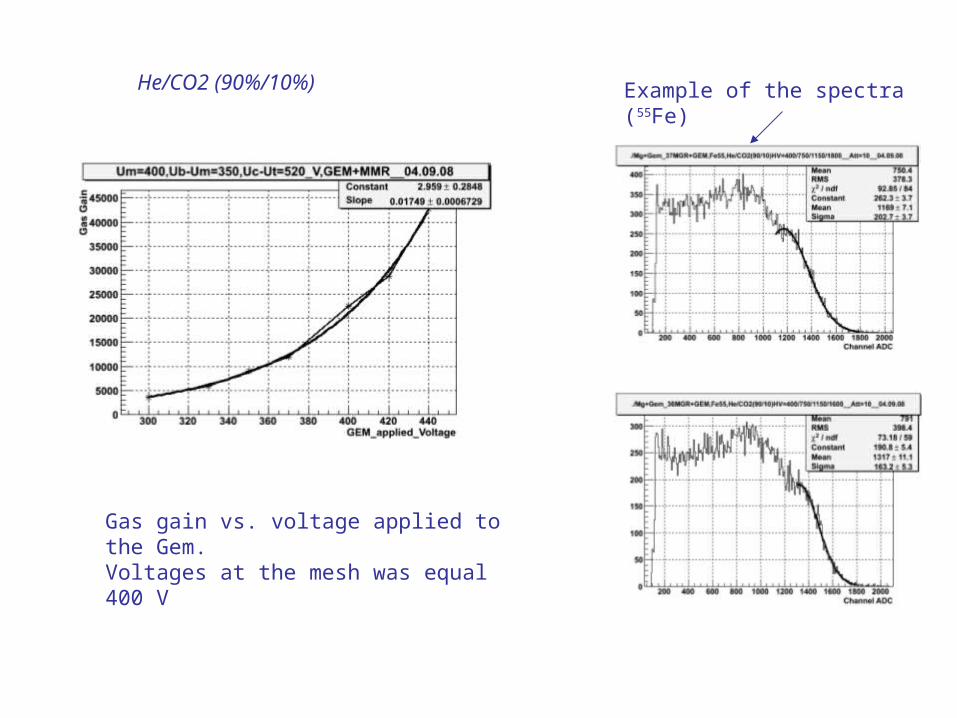
Example of the spectra (55Fe)
Gas gain vs. voltage applied to the Gem.Voltages at the mesh was equal 400 V
He/CO2 (90%/10%)
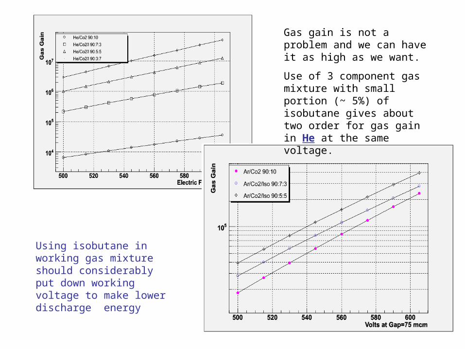
Gas gain is not a problem and we can have it as high as we want.
Use of 3 component gas mixture with small portion (~ 5%) of isobutane gives about two order for gas gain in He at the same voltage.
Using isobutane in working gas mixture should considerably put down working voltage to make lower discharge energy

Scheme for work with β-source (90Sr)
200 μ of FR4+18 μ of Cu
Stainless steel mesh of 60 μ cell And 30 μ wire
400 μ of FR4
Plastic scintillators
Result of GEANT simulation
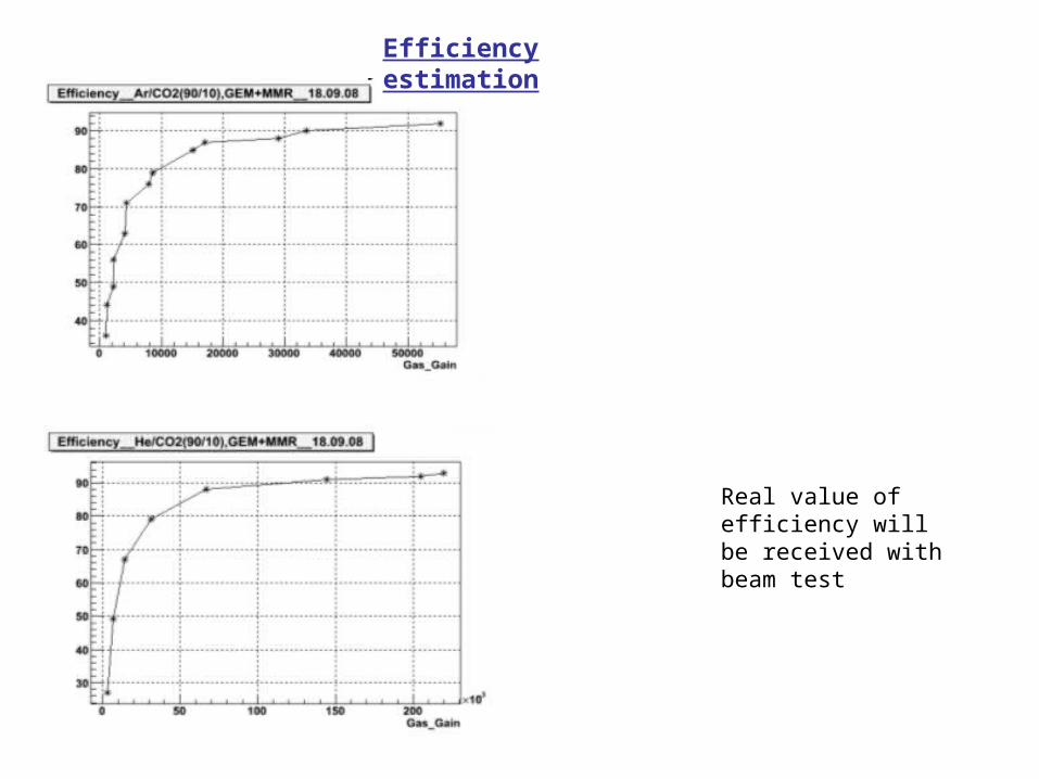
Efficiency estimation
Real value of efficiency will be received with beam test
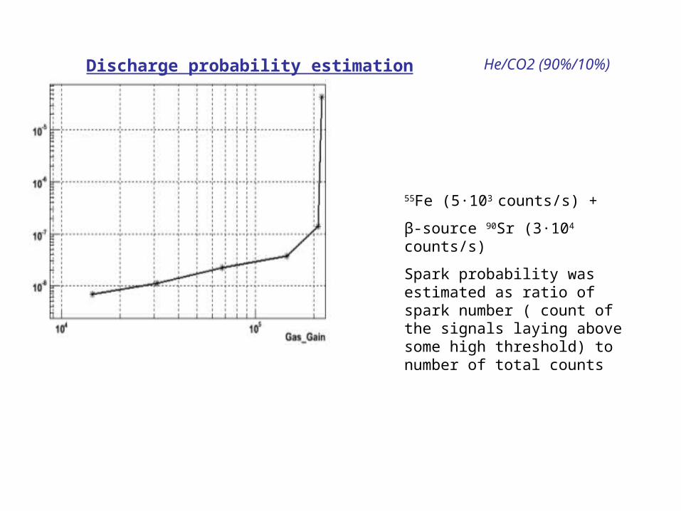
Discharge probability estimation He/CO2 (90%/10%)
55Fe (5∙103 counts/s) +
β-source 90Sr (3∙104 counts/s)
Spark probability was estimated as ratio of spark number ( count of the signals laying above some high threshold) to number of total counts
Summary
● It was assembled prototypes of MICROMEGAS, GEM, and MICROMEGAS+GEM detectors
● Prototypes were tested with radioactive sources 55Fe and 90Sr using Ar/CO2 and He/CO2 gas mixtures
● Gas gain, efficiency and discharge probability estimations were obtained
● From our point combined MICROMEGAS+GEM version is good candidate for MUCH base detector
● Some practical technological requirements and approaches for designing and assembling the beam test prototypes were found
Plans for next year
● Variety of mesh geometry
● Three component gas mixture
● Designing and assembling two prototypes for beam test – MICROMEGAS only, MICROMEGAS+GEM
● Preparing to the beam test


![2SHUDWLRQRIWKH=HUR,RQ%DFNIORZHOHFWURQ … · 2019-05-25 · The development of micro-patterned gaseous electron multipliers such as the Gas Electron Multiplier (GEM) [4], Micromegas](https://img.pdfslide.net/doc/110x75/5e46f41ecb54f851eb09ed28/2shudwlrqriwkhhurrqdfniorzhohfwurq-2019-05-25-the-development-of-micro-patterned.jpg)