Embed Size (px)
Citation preview

Status of procurement of Module Assembly Machines
A. Di Mauro (CERN)5th ITS, MFT and O2 upgrade Asian workshop, Wuhan , 08.06.2015

MAM 2
Summary of financial aspects
Item Cost [Euro]
Development and set-up 226360
CERN prototype (baseline + probe card systems) 202208
Bari (baseline system) 161276
Liverpool (baseline system) 161276
Pusan (baseline + probe card system) 202208
Strasbourg (baseline system) 161276
Wuhan (baseline system) * 161276
Wuhan, 08/06/2015
Contract placed between CERN and IBS-PE (NL):1. Property of machines will remain to CERN for three years2. For EU countries: machines have to be first delivered to CERN for
custom formalities then to final sitesCost include transport, installation and commissioning, documentation and personnel training, 3 y warranty with preventive and corrective maintenance
* Machine for Wuhan ordered separately to simplify procedure (deadline: end of June)

MAM 3
Baseline MAM and purchase options
• The baseline machine will perform semi-automatic or fully automatic placement of chips with ± 5 mm accuracy wrt external markers and interconnection of FPC and chips via automatic soldering by laser of 200 mm Sn/Ag balls
• AOI based on hi-res camera with 1¨ sensor, 2048x2048 pixels, 10x objective, 1.1x1.1 mm field of view, focal depth 3.6 mm, image processing by Labview IMAQ package (expected sub-pixel resolution of 0.25 mm): chips dimensions, edge integrity, pads cleanness and Sn-Ag soldering ball presence in FPC vias
• Purchase options:– Probe card system for electrical chip testing (CERN and Pusan),
included in contract : 40932 Euro– Sn-Ag balls presence in solder ball transfer tool (SBTT): 9928 Euro;
not included for the moment but worth to be considered
Wuhan, 08/06/2015
MAM 4
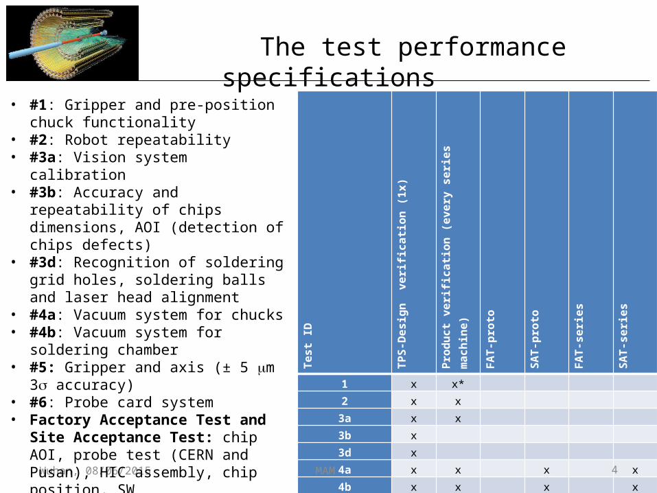
The test performance specifications
Test ID
TPS-Design verification (1x)
Product verification (every series machine)
FAT-proto
SAT-proto
FAT-series
SAT-series
1 x x*
2 x x
3a x x
3b x
3d x
4a x x x x
4b x x x x
5 <-- 6 x x
6 x x**
FAT/SAT-a x x x x
FAT/SAT-b1 x x
FAT/SAT-b2 x x
FAT/SAT-c x x x x
Interface check x x
Wuhan, 08/06/2015
• #1: Gripper and pre-position chuck functionality
• #2: Robot repeatability • #3a: Vision system calibration• #3b: Accuracy and repeatability of
chips dimensions, AOI (detection of chips defects)
• #3d: Recognition of soldering grid holes, soldering balls and laser head alignment
• #4a: Vacuum system for chucks• #4b: Vacuum system for soldering
chamber• #5: Gripper and axis (± 5 mm 3s
accuracy)• #6: Probe card system• Factory Acceptance Test and
Site Acceptance Test: chip AOI, probe test (CERN and Pusan), HIC assembly, chip position, SW

MAM 5Wuhan, 08/06/2015
MAM preliminary layout
(tendering proposal picture, will be updated)

MAM 6
Machine concept
Wuhan, 08/06/2015
• Interface position for the chips tray• Intermediate position between the
tray and the HIC-assembly table: the “pre-position chuck”, where the chip is clamped by vacuum after take-over from the tray.On this chuck the positions of the markers are measured on a flat chip. The pre-position chuck is also used to clamp chips during electrical inspection with the probe card.
• The HIC-assembly table with the vacuum surface to clamp the chips. Reference markers on the HIC-assembly table (as close as possible to the chip markers)
• A chip handling system with a XY-guiding
• A position sensor (vision system) to acquire position data of the markers on chips/table and for chips AOI.
• A gripper for chip take-over by means of a vacuum pad, with actuation of the Z-direction and of the rotation up to 180o about the Z-axis (Rz).
• A laser system for soldering the FPC to the chips by means of soldering balls.
Last added feature: bar code reader• Trays and HICs (TBC) will have a 2D bar code identifier
(coded info TBD)• Chips from half wafer are stored in 24 slot trays,
position in tray (0-23) depends on position in wafer.• Chips will be identified by the tray S/N + position in
tray. The value is hard-coded upon first electrical test by burning fuses of chips.

MAM 7
TABLE OF CONTENTS
1 INTRODUCTION ..................................................................................................................... 4 1.1 REFERENCE DOCUMENTS ............................................................................................................................. 4 1.2 OPEN ISSUE LIST ............................................................................................................................................ 5 1.3 FUNCTIONAL ADDITIONS (CHANGE REQUESTS) ........................................................................................ 6
2 ACCURACY REQUIREMENTS ............................................................................................... 7 2.1 CHIP POSITIONING ACCURACY ..................................................................................................................... 7 2.2 CALIBRATION ACCURACY OF MARKERS ON HIC ASSEMBLY TABLE ..................................................... 7 2.3 CHIP DIMENSION MEASUREMENTS .............................................................................................................. 8 2.4 CHIP DEFECT DETECTION .............................................................................................................................. 8 2.5 LASER HEAD POSITIONING ACCURACY ...................................................................................................... 8 2.6 VACUUM ........................................................................................................................................................... 9 2.7 N2 PURGING ..................................................................................................................................................... 9
3 INTERFACE DEFINITIONS ................................................................................................... 10 3.1 ENVIRONMENTAL CONDITIONS, INPUTS/OUTPUTS ................................................................................. 10 3.2 NETWORK ACCESS ....................................................................................................................................... 11 3.3 SUPPLIES ....................................................................................................................................................... 11
3.3.1 Nitrogen supply ............................................................................................................................................ 11 3.3.1.1 Nitrogen plant supply .......................................................................................................................................... 11 3.3.1.2 Requirements of Nitrogen supply to HIC-assembly table and SBTT .................................................................. 12
3.3.2 Electrical supply ........................................................................................................................................... 12 3.3.3 Pressurized air supply .................................................................................................................................. 13 3.3.4 Exhaust ........................................................................................................................................................ 13
3.4 MATERIALS .................................................................................................................................................... 13 3.4.1 Chip characteristics ...................................................................................................................................... 13
3.4.1.1 Chip orientation ................................................................................................................................................... 14 3.4.1.2 Chips reference markers ...................................................................................................................................... 15 3.4.1.3 Chips serial number used during assembly sequence .......................................................................................... 16
3.4.2 HIC-assembly table ...................................................................................................................................... 16 3.4.2.1 General: geometrical features .............................................................................................................................. 16 3.4.2.2 External reference markers .................................................................................................................................. 17 3.4.2.3 Vacuum ............................................................................................................................................................... 18 3.4.2.4 Z-level reference marker surface ......................................................................................................................... 21 3.4.2.5 Z-level of top of vacuum lid ................................................................................................................................ 21 3.4.2.6 HIC assembly table support ................................................................................................................................. 21 3.4.2.7 Mechanical interfacing and area claim HIC-assembly table and vacuum lid ...................................................... 22 3.4.2.8 Volume conflicts ................................................................................................................................................. 23
3.4.3 FPC .............................................................................................................................................................. 24 3.4.4 Tray .............................................................................................................................................................. 24 3.4.5 Solder Ball Transfer Tool ............................................................................................................................. 26 3.4.6 Probe card handler ...................................................................................................................................... 27 3.4.7 Probe card control station ............................................................................................................................ 27
3.5 HUMAN-MACHINE INTERFACES .................................................................................................................. 27
4 UPDATED MACHINE CONCEPT .......................................................................................... 28 4.1 CHIP HANDLING ACCURACY ANALYSIS .................................................................................................... 29
Wuhan, 08/06/2015
Summary of main interfaces specification
Environmental conditions, network, supplies
Assembly table
Overview of specifications and interfaces
Author:
Project number:
Last update:
IBSPE222282015-05-26
Ergonomics issues

MAM 8
MAM preliminary footprint
Wuhan, 08/06/2015
Machine
1600
1100
Elec
cab
inet
600
800
Work table: HMI Machine
Probe card station
1000
800
100
1900
2700
Vacu
um p
ump
300100100
CHAIR
800
Preliminary weight: ~1400 kg

MAM 9
Lab requirementsNR Description Value Uni
tComment
1 Temperature range 20 ± 2 C2 Relative humidity 30-60 % Non-condensing3 Floor vibration level compliant with vibration criterion
C -
4 Heat in (to machine)
Machine should not be placed in vicinity of radiating heat sources
-
Wuhan, 08/06/2015
[1] Colin G. Gordon, Generic criteria for vibration-sensitive equipment. http://www.colingordon.co/library-generic-vibration-criteria-for-vibration-sensitive-equipment
Laboratory features have to be measured and compared to suggested Vibration Criteria.If necessary decoupling platform will have to be installed.

MAM 10
Lab requirements
Wuhan, 08/06/2015
• Network accessRemote access to the HIC assembly machine is required for first line diagnosis. Furthermore data generated during HIC-assembly process must be stored on a server connected to the plant network
• PC OSInstallation of PC (OS, virus scanner, firewall) supplied by IBS done by institute? Issues with respect to remote access, update of OS (not automatic) and virus scanner, no automatic updates of machine software to be verified.

MAM 11
Lab requirements
Wuhan, 08/06/2015
• N2 supply
N2 is used for flushing soldering chamber and releasing soldering balls. In addition it could be used to keep clean FPC under gas prior to assembly. Pollution (dust, water, grease) will have a direct impact on soldering efficiency.Nitrogen-60 + silicon/grease-free SS pipes + 0.5 mm filter (e.g. Swagelok SS-6F-MM-05)
• Internal requirement: clean room of at least 100000 class
NR Description Value Unit Comment1 Pressure 2 bara2 Flow >1 l/min Non-condensing3 Quality TBD 4 Connection Pipe diam.: 10 mm - both female and male connector
are delivered by the customer (being CERN/institutes)

MAM 12
Lab requirements
Wuhan, 08/06/2015
• Pressurised air supply
Filters for particles, oil and water to be installed
• ExhaustConnections: DN 16 ISO KF
NR Description Value Unit Comment1 Pressure 6 barg 7 bar, 80 nl/min
2 Flow > 10 l/min 3 Quality class 3.3.3 - Purity class 3.3.3 (A,B,C acc. ISO 8573.1)
Solid particles per m3:
1…5 micron: 500.5…1 micron: 10.000 Oil, including vapor: < 1 mg/m3
Water content @ 7 bar:pressure dew point: < -20 ºC
4 Connection Pipe diam.: 10 mm
- both female and male connector are delivered by the customer (being CERN/institutes)

MAM 13
Lab requirements
Wuhan, 08/06/2015
• Electrical power
Filters for particles, oil and water to be installed
NR Description Value Unit Comment 1 Electrical
power3P+N+G - 3 phases +neutral + ground
2 Voltage 400 V tolerance ±10%3 Frequency 50 Hz ±0,1 Hz; TBD2 Current 16 AC 3 Mean power
consumption HIC assembly machine
TBD W Mean power consumption of machine to be confirmed by IBS
4 Peak power HIC assembly machine
TBD W
5 Connector male - 5 pins acc. to IEC 60309; HIC assembly machine side

MAM 14
Assembly table interfacing
• 3 different tables for IB, OB and MFT (module size: 1x9 chips, 2x7 chips 1x1-5 chips, respectively)
• 3 different approaches for FPC mounting and alignment
Wuhan, 08/06/2015

MAM 15
Assembly table interfacing
Wuhan, 08/06/2015
IB: Flex-frame with dowels to mount and align FPC
Cover with quartz window
Stave gluing vacuum chuck
Flex-frame
FPCChips (1x9)
Chips vacuum chuck
Base plate

MAM 16
Assembly table interfacing
Wuhan, 08/06/2015
IB

MAM 17
Assembly table interfacing
Wuhan, 08/06/2015
IB

MAM 18
Assembly table interfacing
Wuhan, 08/06/2015
IB

MAM 19
Assembly table interfacing
Wuhan, 08/06/2015
IB
Soldering grid

MAM 20
Assembly table interfacing
Wuhan, 08/06/2015
IB

MAM 21
Assembly table interfacing
Wuhan, 08/06/2015
IB

MAM 22
Assembly table interfacing
Wuhan, 08/06/2015
OB: mount and align FPC using dowels and ruby balls on vacuum chuck (removable frame to avoid interference with gripper while placing chips) – see V. Manzari’s talk

MAM 23
Assembly table interfacing
Wuhan, 08/06/2015
MFT: mount and align FPC using removable dowels on vacuum chuck (to avoid interference with gripper while placing chips) – see G. Martinez’s talk

MAM 24
Assembly table interfacing
Wuhan, 08/06/2015
Bottom interface plate common to all tables (IB, OB, MFT) to implement connections with vacuum/gas systems

MAM 25
Assembly table interfacing
Wuhan, 08/06/2015

MAM 26
Reference markers
• Chips are placed on vacuum chuck using external markers implemented on assembly table
• Request from IBS: to align to nominal position of pALPIDE3 chips markers, increase distance from 300 mm to 450.6 mm
Wuhan, 08/06/2015 100175,32
76,8
0
Ø200
300
150
50
200
300
1100
1100
300
50
HIC ASSEMBLY TABLE
LOCAL REFERENCE MARKER
CHIP MARKER
CHIP CLAMPING SURFACE
DIMENSIONS IN µm
FIELD OF VIEW 1,1x1,1 MM2
pALPIDE3 layout

MAM 27
Reference markers
Wuhan, 08/06/2015
• Test by mechanical drilling of 36 holes (0.25 mm diameter, 0.4 mm deep)
• Diameter: 261.9 ± 1.2 mm
• Position deviation from nominal: -1.8 ± 1.2 mm
• Accuracy OK for MAM, issue with light reflection from hole bottom, fill with black ink to enhance contrast

MAM 28
Ergonomics issues
Wuhan, 08/06/2015
• All manual tasks in standing position• Distance from assembly table crucial for delicate intervention like
placement of single balls or correction of ball placement faults

MAM 29
Ergonomics issues
Wuhan, 08/06/2015
• To ensure required accuracy the assembly table has to be as close as possible to linear actuator and drive
• Distance to assembly table ~ 305 mm (3x8 chips tray layout) seems reasonable
• Develop specific tool(s) for such interventions

MAM 30
Preliminary GUI: initialization
Wuhan, 08/06/2015

MAM 31
Preliminary GUI: select chips
Wuhan, 08/06/2015

MAM 32
Preliminary GUI: chip AOI
Wuhan, 08/06/2015

MAM 33
Preliminary GUI: select HIC position
Wuhan, 08/06/2015

MAM 34
Preliminary GUI: chip position check
Wuhan, 08/06/2015

MAM 35
Preliminary GUI: pad inspection
Wuhan, 08/06/2015

MAM 36
Preliminary GUI: ball placement inspection
Wuhan, 08/06/2015

MAM 37
Preliminary GUI: final position check
Wuhan, 08/06/2015

MAM 38
Integration of probe card system
• Finalization of specifications ~ completed (J-F Grosse-Oetringhous, Y. Kwon)
• Main features: – 2D (Y,Z dedicated axes) displacement– mechanical alignment along X– Budget for needle placement: pad position on pre-pos
chuck 6 mm + needles probe card position 28 mm + sliding of needles during overdrive 40 mm = 74 mm → no issues (even assuming contact pads diameter of 260 mm)
Wuhan, 08/06/2015

MAM 39
Integration of probe card system
• Budget for z-overdrive for electrical contact
50 mm overdrive at the edge of estimated budget Wuhan, 08/06/2015
description
value (mm)
Needle plane flatness
10
Card deflection
10
Card alignment ZRxRy
10
Z step 5
Chip thickness variation
2
Chuck flatness
5
Budget to contact all needles
42

MAM 40
Key milestones and deliverables
Wuhan, 08/06/2015
Schedule has been revised according to changes in chips (pALPIDE2 and 3), assembly table and probe-card availability
TASK Previous deadline New deadline
Delivery chips (pALPIDE2: 10 pad, 100 real) and trays proto for testing
Wk24 Wk25: 10 pad + 20 pALPIDE2; Wk35: 80 pALPIDE2
MS1.2: Design presentation and approval Wk25 (19/06/2015) 26/06/2015 (TBC)
Delivery probe card, PC and SW Wk25 Wk32 * (Wk40 pALPIDE3)
Delivery HIC assembly tables Wk32 (07/08/3015) ~ok for IB, MFT, TBC for OB
Delivery chips in tray (pALPIDE3 + final trays)
Wk32 Wk38
MS1.4 prototype FAT and approval Wk42 (16/10/2015) TBC by IBS
MS1.5 prototype SAT and approval Wk44 (30/10/2015) TBC by IBS
All other machines will be delivered in the various sites starting 29 weeks after prototype SAT, every 2 weeks (presumably between June and September 2016)


![[MFT] Toriko 161](https://img.pdfslide.net/doc/110x75/568c0d191a28ab955a8b71e1/mft-toriko-161-56e4d6247d1d9.jpg)
![[MFT] beelzebub 128](https://img.pdfslide.net/doc/110x75/568bde421a28ab2034b8d26b/mft-beelzebub-128.jpg)
