Embed Size (px)
DESCRIPTION
Status of RF Modulators for Enhanced and Advanced LIGO. Volker Quetschke for the LIGO-UF group University of Florida Supported by NSF grant PHY-0555453. Optics WG, September 24, 2008. Outline. eLIGO modulator design eLIGO modulator commissioning aLIGO modulator prototype - PowerPoint PPT Presentation
Citation preview
LIGO-G080483-00-R
L IG O
Status of RF Modulators for Enhancedand Advanced LIGO
Optics WG, September 24, 2008
Volker Quetschke
for the LIGO-UF group
University of Florida
Supported by NSF grant PHY-0555453
LIGO-G080483-00-R
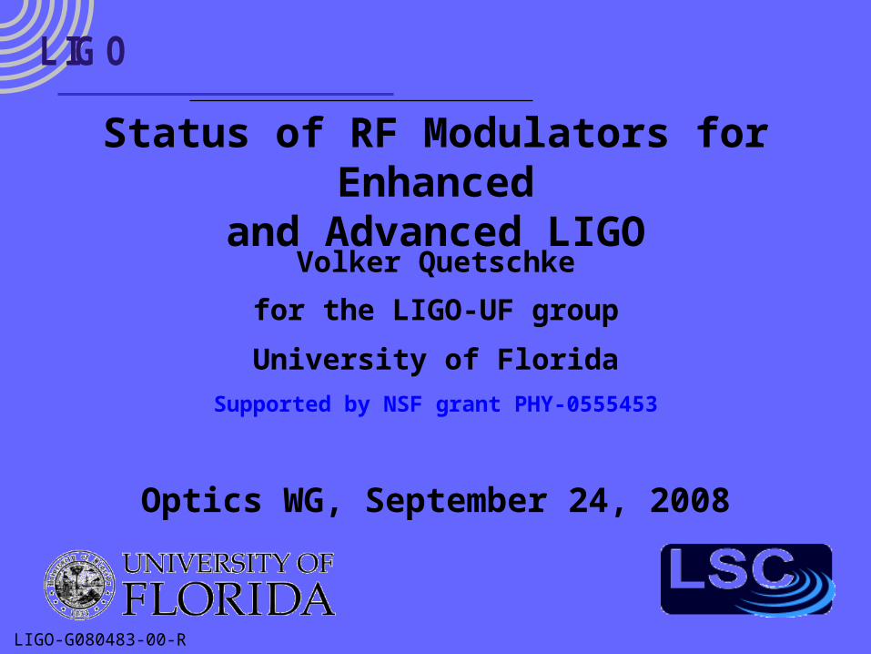
L IG O Outline
eLIGO modulator design
eLIGO modulator commissioning
aLIGO modulator prototype
aLIGO parallel modulation scheme
LIGO-G080483-00-R
L IG O eLIGO phase modulator
LIGO is currently being upgraded to eLIGO
Laser power is increased to 30 W
iLIGO electro-optic modulators (EOMs) must be replaced– LiNbO3 modulators would suffer from severe
thermal lensing or might even break
eLIGO devices (techniques) serve as testbed for aLIGO
LIGO-G080483-00-R
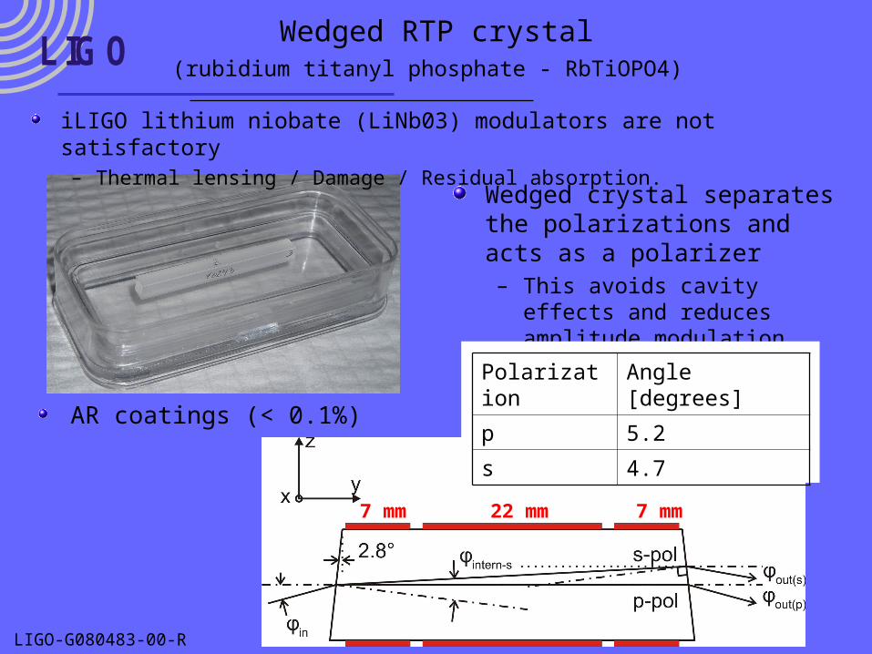
L IG OWedged RTP crystal
(rubidium titanyl phosphate - RbTiOPO4)
Wedged crystal separates the polarizations and acts as a polarizer– This avoids cavity effects and
reduces amplitude modulation
Polarization Angle [degrees]
p 5.2
s 4.7AR coatings (< 0.1%)
7 mm 22 mm 7 mm
iLIGO lithium niobate (LiNb03) modulators are not satisfactory – Thermal lensing / Damage / Residual absorption.
LIGO-G080483-00-R
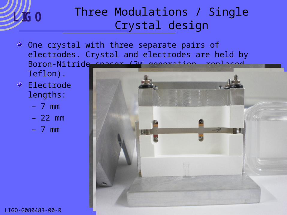
L IG O Three Modulations / Single Crystal design
One crystal with three separate pairs of electrodes. Crystal and electrodes are held by Boron-Nitride spacer (2nd generation, replaced Teflon).
Electrodelengths:– 7 mm– 22 mm– 7 mm
LIGO-G080483-00-R
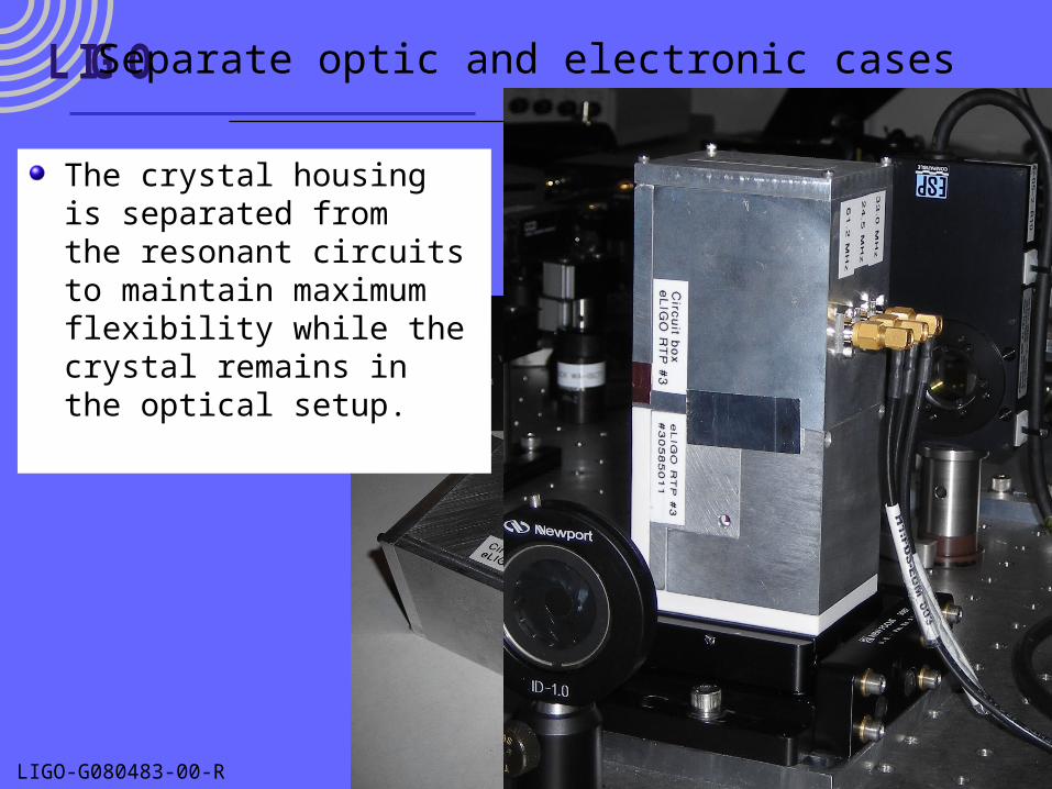
L IG O Separate optic and electronic cases
The crystal housingis separated fromthe resonant circuitsto maintain maximum flexibility while thecrystal remains inthe optical setup.
LIGO-G080483-00-R
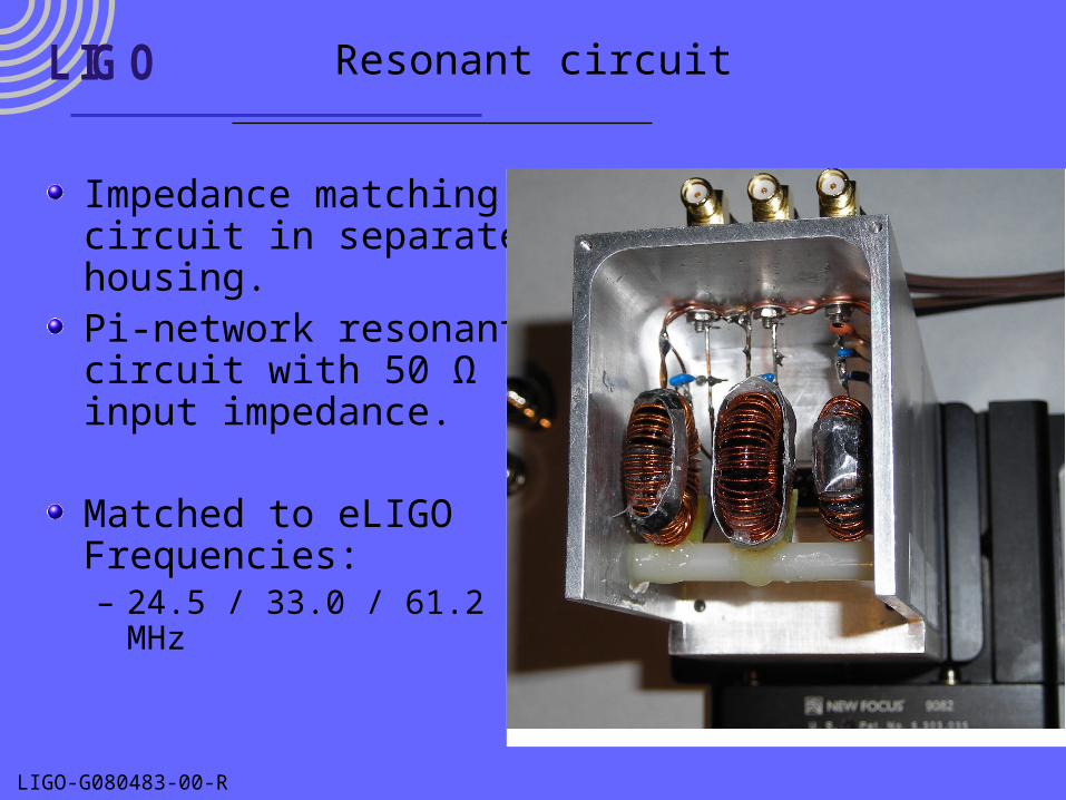
L IG O Resonant circuit
Impedance matching circuit in separatehousing.Pi-network resonant circuit with 50 Ω input impedance.
Matched to eLIGO Frequencies:– 24.5 / 33.0 / 61.2 MHz
LIGO-G080483-00-R
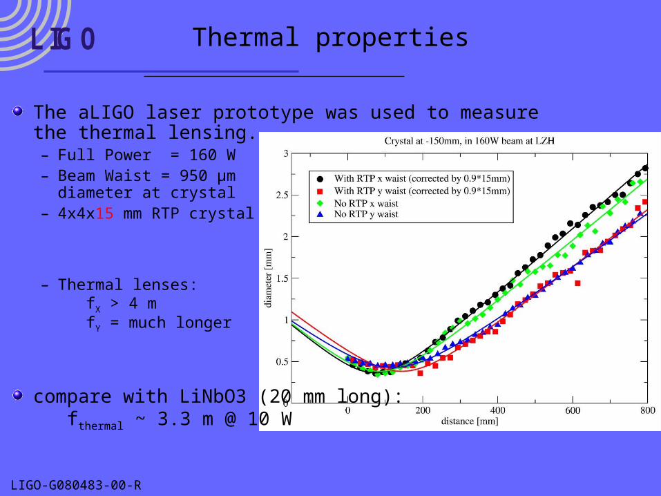
L IG O Thermal properties
The aLIGO laser prototype was used to measure the thermal lensing.– Full Power = 160 W– Beam Waist = 950 µm
diameter at crystal– 4x4x15 mm RTP crystal
– Thermal lenses: fX > 4 m fY = much longer
compare with LiNbO3 (20 mm long): fthermal ~ 3.3 m @ 10 W
LIGO-G080483-00-R
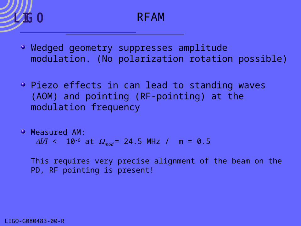
L IG O RFAM
Wedged geometry suppresses amplitude modulation. (No polarization rotation possible)
Piezo effects in can lead to standing waves (AOM) and pointing (RF-pointing) at the modulation frequency
Measured AM: I/I < 10-6 at mod = 24.5 MHz / m = 0.5
This requires very precise alignment of the beam on the PD, RF pointing is present!
LIGO-G080483-00-R
L IG O eLIGO modulator commissioning
Installed at LHO– drive electronics changed to output 24dBm– installed after PMC, before power control.
EOM always sees maximum power (~28W)– Modulation indices
• 24.5MHz: m=0.50 @ 12.0Vpp• 33.3MHz: m=0.094 @ 5.0Vpp• 61.2MHz: m=0.146 @ 8.6Vpp
– MC visibility 98%
Installation at LLO is scheduled for the week of 10/20/2008.
LIGO-G080483-00-R
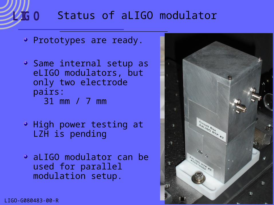
L IG O Status of aLIGO modulator
Prototypes are ready.
Same internal setup as eLIGO modulators, but only two electrode pairs: 31 mm / 7 mm
High power testing at LZH is pending
aLIGO modulator can be used for parallel modulation setup.
LIGO-G080483-00-R
L IG O
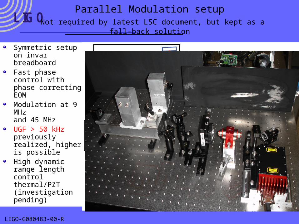
Symmetric setup on invar breadboardFast phase control with phase correcting EOMModulation at 9 MHzand 45 MHzUGF > 50 kHz previously realized, higher is possibleHigh dynamic range length control thermal/PZT(investigation pending)
Parallel Modulation setup Not required by latest LSC document, but kept as a fall-back solution
LIGO-G080483-00-R
L IG O Summary
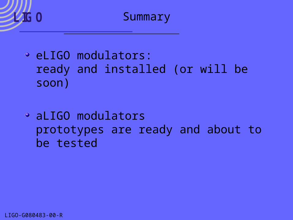
eLIGO modulators:ready and installed (or will be soon)
aLIGO modulatorsprototypes are ready and about to be tested
LIGO-G080483-00-R
L IG O Supplementary material
LIGO-G080483-00-R
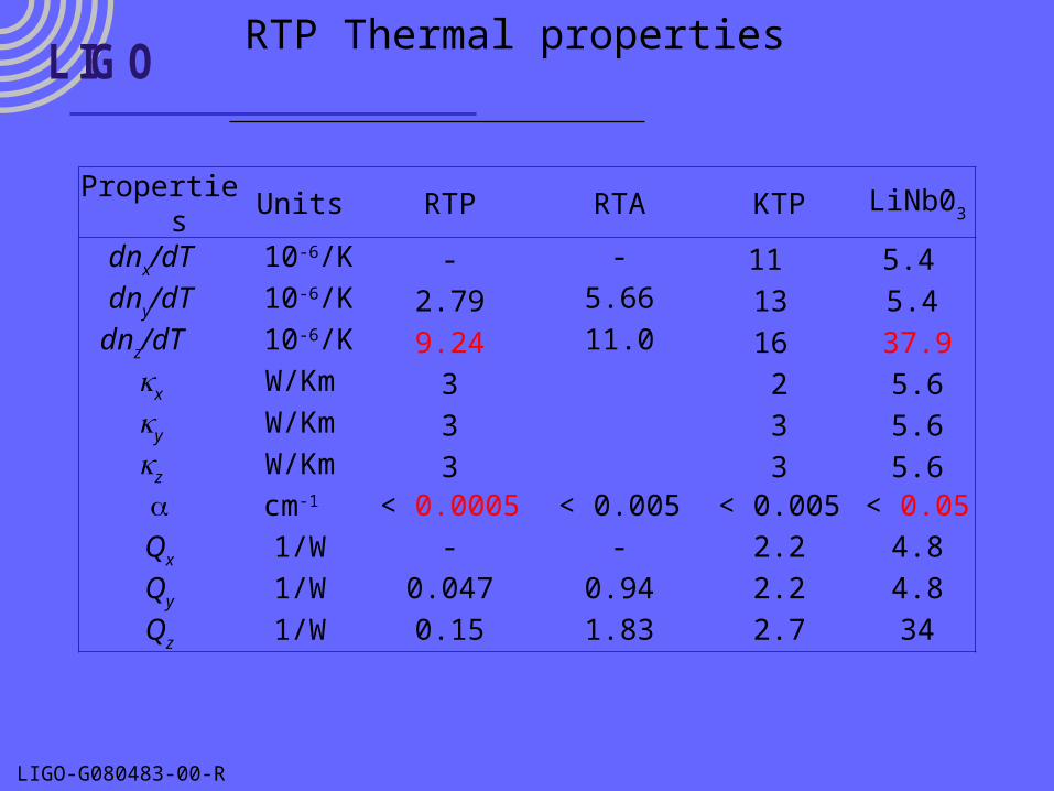
L IG ORTP Thermal properties
Properties Units RTP RTA KTP LiNb03
dnx/dT 10-6/K - - 11 5.4 dny/dT 10-6/K 2.79 5.66 13 5.4
dnz/dT 10-6/K 9.24 11.0 16 37.9x W/Km 3 2 5.6y W/Km 3 3 5.6z W/Km 3 3 5.6 cm-1 < 0.0005 < 0.005 < 0.005 < 0.05Qx 1/W - - 2.2 4.8
Qy 1/W 0.047 0.94 2.2 4.8
Qz 1/W 0.15 1.83 2.7 34
LIGO-G080483-00-R
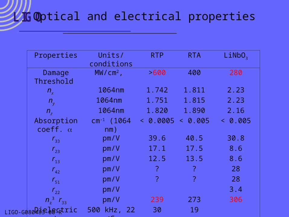
L IG O Optical and electrical properties
Properties Units/conditions RTP RTA LiNbO3
Damage Threshold MW/cm2, >600 400 280nx 1064nm 1.742 1.811 2.23
ny 1064nm 1.751 1.815 2.23
nz 1064nm 1.820 1.890 2.16
Absorption coeff. cm-1 (1064 nm) < 0.0005 < 0.005 < 0.005r33 pm/V 39.6 40.5 30.8
r23 pm/V 17.1 17.5 8.6
r13 pm/V 12.5 13.5 8.6
r42 pm/V ? ? 28
r51 pm/V ? ? 28
r22 pm/V 3.4
nz3 r33 pm/V 239 273 306
Dielectric const., z 500 kHz, 22 oC 30 19
Conductivity, z cm-1, 10 MHz ~10-9 3x10⁻⁷
Loss Tangent, dz 500 kHz, 22 oC 1.18 -