Embed Size (px)
Citation preview
HAL Id: cea-02506798https://hal-cea.archives-ouvertes.fr/cea-02506798
Submitted on 12 Mar 2020
HAL is a multi-disciplinary open accessarchive for the deposit and dissemination of sci-entific research documents, whether they are pub-lished or not. The documents may come fromteaching and research institutions in France orabroad, or from public or private research centers.
L’archive ouverte pluridisciplinaire HAL, estdestinée au dépôt et à la diffusion de documentsscientifiques de niveau recherche, publiés ou non,émanant des établissements d’enseignement et derecherche français ou étrangers, des laboratoirespublics ou privés.
Status of the Sodium Gas Heat Exchanger (SGHE)development for the Nitrogen Power Conversion System
planned for the ASTRID SFR prototypeL. Cachon, C. Vitillo, C. Garnier, X. Jeanningros, E. Rigal, F. Le Bourdais, S.
Madeleine, O. Gastaldi, G. Laffont
To cite this version:L. Cachon, C. Vitillo, C. Garnier, X. Jeanningros, E. Rigal, et al.. Status of the Sodium Gas HeatExchanger (SGHE) development for the Nitrogen Power Conversion System planned for the ASTRIDSFR prototype. ICAPP 2015 - International Congress on Advances on nuclear Power Plants, May2015, Nice, France. paper 15362. �cea-02506798�
Proceedings of ICAPP 2015 May 03-06, 2015 - Nice (France)
Paper 15362
Status of the Sodium Gas Heat Exchanger (SGHE) development for the Nitrogen Power Conversion System planned for the ASTRID SFR prototype
L. CACHON, F. VITILLO, Ch. GARNIER, X. JEANNINGROS, E. RIGAL1, F. LE BOURDAIS2, S. MADELEINE, O. GASTALDI, G. LAFFONT
French Alternative Energies and Atomic Energy Commission, F- 13 108 Saint PAUL Lez Durance, France 1French Alternative Energies and Atomic Energy Commission, F- 38 054 GRENOBLE, France 2French Alternative Energies and Atomic Energy Commission, F- 91 191 Gif sur Yvette, France
Email:[email protected]
Abstract – In the framework of the CEA R&D program developing the Advanced Sodium
Technological Reactor for Industrial Demonstration (ASTRID), the present work describes the current status of an innovative compact heat exchanger and highlights the industrial challenges this technology raises. One of the main innovative options under investigation for ASTRID is the use of a Brayton cycle gas-power conversion system. This system permits to avoid the energetic
sodium-water interaction, which can occur in steam generators in case of tube failure if a traditional Rankine cycle is used. In this novel concept, steam generators would be replaced by the
Sodium Gas Heat Exchanger (SGHE). The first part of this paper presents the details of the original design of this heat exchanger which allows a high thermal compactness. The main studies supporting this development are described in the second part of the paper. The thermal hydraulic
program demonstrates the potential of the technology used. An innovative geometry is also studied on the gas side improving the thermal compactness. Thermomechanical analyses show the good
behavior of this exchanger under the ASTRID operating conditions. The manufacturing / welding process optimization is ongoing in order to produce a component with nuclear specifications.
Specific sensors and control techniques are also being developed in order to assess the manufacturing process quality and to allow future in-service inspections. At last, the qualification
program is presented and the first results obtained on an operating small scale SGHE mock up working under ASTRID conditions are described.
I. INTRODUCTION In the framework of the CEA R&D program
developing the Advanced Sodium Technological Reactor for Industrial Demonstration (ASTRID), the present work describes the current status of an innovative compact heat exchanger and highlights the industrial challenges this technology raised. One of the main innovative options under investigation for ASTRID is the use of a Brayton cycle gas-power conversion system. This system permits to avoid the energetic sodium-water interaction, which can occur in steam generators in case of tube failure if a traditional Rankine cycle is used. In this novel concept, steam generators would be replaced by a Sodium Gas Heat Exchanger (SGHE) [1][2].
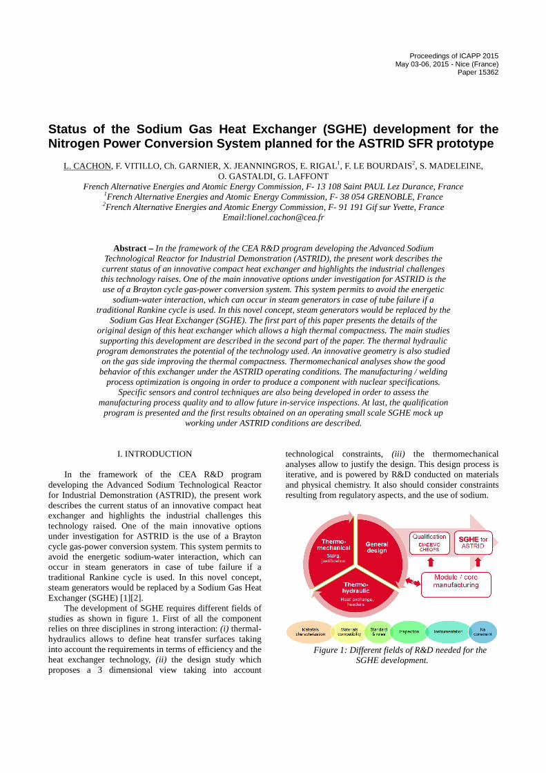
The development of SGHE requires different fields of studies as shown in figure 1. First of all the component relies on three disciplines in strong interaction: (i) thermal-hydraulics allows to define heat transfer surfaces taking into account the requirements in terms of efficiency and the heat exchanger technology, (ii) the design study which proposes a 3 dimensional view taking into account
technological constraints, (iii) the thermomechanical analyses allow to justify the design. This design process is iterative, and is powered by R&D conducted on materials and physical chemistry. It also should consider constraints resulting from regulatory aspects, and the use of sodium.
Figure 1: Different fields of R&D needed for the
SGHE development.
Proceedings of ICAPP 2015 May 03-06, 2015 - Nice (France)
Paper 15362
It is required that the designed object is industrially doable: the design must take into account the specificities of the assembly process envisaged for the manufacture of the exchanger. Therefore there is a strong interaction between the teams developing the assembly process and those in charge of the design. Finally, the validation of both the design and manufacturing is made through a number of validation phases at different scales before proposing a SGHE in its final version.
The first part of this paper presents the details of the original design of this heat exchanger which allows a high thermal compactness. The main studies supporting this development are described in the second part of the paper. The thermal-hydraulic program demonstrates the potential of the used technology, also with an innovative flow in the gas side improving the thermal compactness of the heat exchanger. Thermomechanical analyses show the good behavior of this exchanger under the ASTRID operating conditions. The manufacturing / welding process optimization is ongoing in order to produce a component with nuclear specifications. Specific sensors and control techniques are also being developed in order to assess the manufacturing process quality and to allow future in-service inspections. At last, the qualification program is presented and the first results obtained on an operating small scale SGHE mock up working under ASTRID conditions are described.
II. SODIUM GAS HEAT EXCHANGER DESIGN
The SGHE has to transfer a total heat power of
1500 MWth between the 4 secondary sodium loops and the 8 gas loops of the power conversion system. The main working conditions of this heat exchanger are summarized in Table 1. Taking into account the low intrinsic heat transfer capacity of the nitrogen, the design is based on compact plate heat exchangers technology [1].
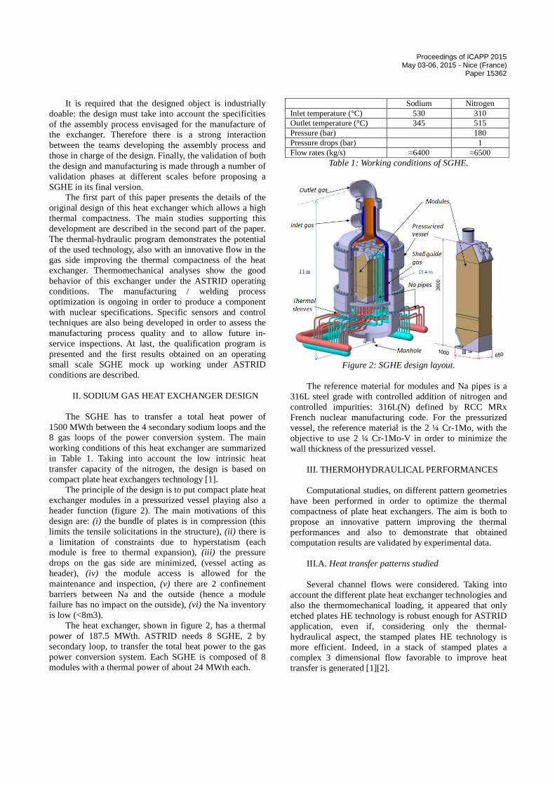
The principle of the design is to put compact plate heat exchanger modules in a pressurized vessel playing also a header function (figure 2). The main motivations of this design are: (i) the bundle of plates is in compression (this limits the tensile solicitations in the structure), (ii) there is a limitation of constraints due to hyperstatism (each module is free to thermal expansion), (iii) the pressure drops on the gas side are minimized, (vessel acting as header), (iv) the module access is allowed for the maintenance and inspection, (v) there are 2 confinement barriers between Na and the outside (hence a module failure has no impact on the outside), (vi) the Na inventory is low (<8m3).
The heat exchanger, shown in figure 2, has a thermal power of 187.5 MWth. ASTRID needs 8 SGHE, 2 by secondary loop, to transfer the total heat power to the gas power conversion system. Each SGHE is composed of 8 modules with a thermal power of about 24 MWth each.
Sodium Nitrogen Inlet temperature (°C) 530 310 Outlet temperature (°C) 345 515 Pressure (bar) 180 Pressure drops (bar) 1 Flow rates (kg/s) ≈6400 ≈6500
Table 1: Working conditions of SGHE.
Figure 2: SGHE design layout.
The reference material for modules and Na pipes is a
316L steel grade with controlled addition of nitrogen and controlled impurities: 316L(N) defined by RCC MRx French nuclear manufacturing code. For the pressurized vessel, the reference material is the 2 ¼ Cr-1Mo, with the objective to use 2 ¼ Cr-1Mo-V in order to minimize the wall thickness of the pressurized vessel.
III. THERMOHYDRAULICAL PERFORMANCES Computational studies, on different pattern geometries
have been performed in order to optimize the thermal compactness of plate heat exchangers. The aim is both to propose an innovative pattern improving the thermal performances and also to demonstrate that obtained computation results are validated by experimental data.
III.A. Heat transfer patterns studied Several channel flows were considered. Taking into
account the different plate heat exchanger technologies and also the thermomechanical loading, it appeared that only etched plates HE technology is robust enough for ASTRID application, even if, considering only the thermal-hydraulical aspect, the stamped plates HE technology is more efficient. Indeed, in a stack of stamped plates a complex 3 dimensional flow favorable to improve heat transfer is generated [1][2].
Proceedings of ICAPP 2015 May 03-06, 2015 - Nice (France)
Paper 15362
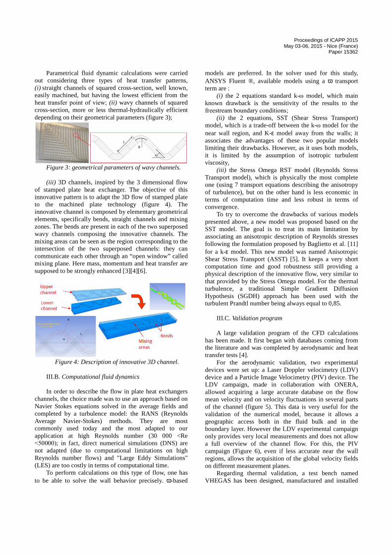
Parametrical fluid dynamic calculations were carried out considering three types of heat transfer patterns, (i) straight channels of squared cross-section, well known, easily machined, but having the lowest efficient from the heat transfer point of view; (ii) wavy channels of squared cross-section, more or less thermal-hydraulically efficient depending on their geometrical parameters (figure 3);
Figure 3: geometrical parameters of wavy channels. (iii) 3D channels, inspired by the 3 dimensional flow
of stamped plate heat exchanger. The objective of this innovative pattern is to adapt the 3D flow of stamped plate to the machined plate technology (figure 4). The innovative channel is composed by elementary geometrical elements, specifically bends, straight channels and mixing zones. The bends are present in each of the two superposed wavy channels composing the innovative channels. The mixing areas can be seen as the region corresponding to the intersection of the two superposed channels: they can communicate each other through an “open window” called mixing plane. Here mass, momentum and heat transfer are supposed to be strongly enhanced [3][4][6].
Figure 4: Description of innovative 3D channel.
III.B. Computational fluid dynamics In order to describe the flow in plate heat exchangers
channels, the choice made was to use an approach based on Navier Stokes equations solved in the average fields and completed by a turbulence model: the RANS (Reynolds Average Navier-Stokes) methods. They are most commonly used today and the most adapted to our application at high Reynolds number (30 000 <Re <50000); in fact, direct numerical simulations (DNS) are not adapted (due to computational limitations on high Reynolds number flows) and "Large Eddy Simulations" (LES) are too costly in terms of computational time.
To perform calculations on this type of flow, one has to be able to solve the wall behavior precisely. ω-based
models are preferred. In the solver used for this study, ANSYS Fluent ®, available models using a ω transport term are :
(i) the 2 equations standard k-ω model, which main known drawback is the sensitivity of the results to the freestream boundary conditions;
(ii) the 2 equations, SST (Shear Stress Transport) model, which is a trade-off between the k-ω model for the near wall region, and K-ε model away from the walls; it associates the advantages of these two popular models limiting their drawbacks. However, as it uses both models, it is limited by the assumption of isotropic turbulent viscosity,
(iii) the Stress Omega RST model (Reynolds Stress Transport model), which is physically the most complete one (using 7 transport equations describing the anisotropy of turbulence), but on the other hand is less economic in terms of computation time and less robust in terms of convergence.
To try to overcome the drawbacks of various models presented above, a new model was proposed based on the SST model. The goal is to treat its main limitation by associating an anisotropic description of Reynolds stresses following the formulation proposed by Baglietto et al. [11] for a k-ε model. This new model was named Anisotropic Shear Stress Transport (ASST) [5]. It keeps a very short computation time and good robustness still providing a physical description of the innovative flow, very similar to that provided by the Stress Omega model. For the thermal turbulence, a traditional Simple Gradient Diffusion Hypothesis (SGDH) approach has been used with the turbulent Prandtl number being always equal to 0,85.
III.C. Validation program A large validation program of the CFD calculations
has been made. It first began with databases coming from the literature and was completed by aerodynamic and heat transfer tests [4].
For the aerodynamic validation, two experimental devices were set up: a Laser Doppler velocimetry (LDV) device and a Particle Image Velocimetry (PIV) device. The LDV campaign, made in collaboration with ONERA, allowed acquiring a large accurate database on the flow mean velocity and on velocity fluctuations in several parts of the channel (figure 5). This data is very useful for the validation of the numerical model, because it allows a geographic access both in the fluid bulk and in the boundary layer. However the LDV experimental campaign only provides very local measurements and does not allow a full overview of the channel flow. For this, the PIV campaign (Figure 6), even if less accurate near the wall regions, allows the acquisition of the global velocity fields on different measurement planes.
Regarding thermal validation, a test bench named VHEGAS has been designed, manufactured and installed
Proceedings of ICAPP 2015 May 03-06, 2015 - Nice (France)
Paper 15362
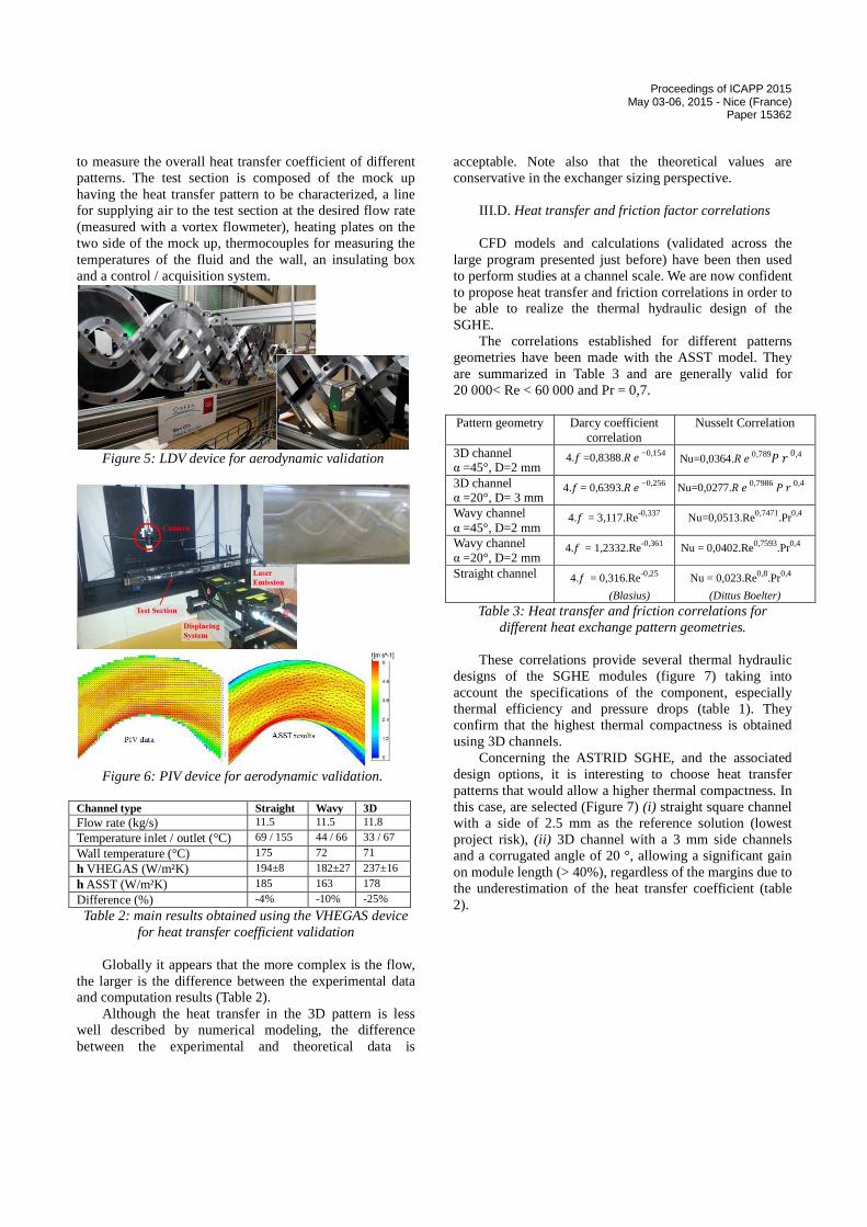
to measure the overall heat transfer coefficient of different patterns. The test section is composed of the mock up having the heat transfer pattern to be characterized, a line for supplying air to the test section at the desired flow rate (measured with a vortex flowmeter), heating plates on the two side of the mock up, thermocouples for measuring the temperatures of the fluid and the wall, an insulating box and a control / acquisition system.
Figure 5: LDV device for aerodynamic validation
Figure 6: PIV device for aerodynamic validation.
Channel type Straight Wavy 3D Flow rate (kg/s) 11.5 11.5 11.8
Temperature inlet / outlet (°C) 69 / 155 44 / 66 33 / 67
Wall temperature (°C) 175 72 71
h VHEGAS (W/m²K) 194±8 182±27 237±16
h ASST (W/m²K) 185 163 178
Difference (%) -4% -10% -25%
Table 2: main results obtained using the VHEGAS device for heat transfer coefficient validation
Globally it appears that the more complex is the flow,
the larger is the difference between the experimental data and computation results (Table 2).
Although the heat transfer in the 3D pattern is less well described by numerical modeling, the difference between the experimental and theoretical data is
acceptable. Note also that the theoretical values are conservative in the exchanger sizing perspective.
III.D. Heat transfer and friction factor correlations CFD models and calculations (validated across the
large program presented just before) have been then used to perform studies at a channel scale. We are now confident to propose heat transfer and friction correlations in order to be able to realize the thermal hydraulic design of the SGHE.
The correlations established for different patterns geometries have been made with the ASST model. They are summarized in Table 3 and are generally valid for 20 000< Re < 60 000 and Pr = 0,7.
Pattern geometry Darcy coefficient
correlation Nusselt Correlation
3D channel α =45°, D=2 mm
4.�=0,8388.��−0,154 Nu=0,0364.��0,789��0,4
3D channel α =20°, D= 3 mm
4.�= 0,6393.��−0,256 Nu=0,0277.��0,7986 ��0,4
Wavy channel α =45°, D=2 mm
4.� = 3,117.Re-0,337 Nu=0,0513.Re0,7471.Pr0,4
Wavy channel α =20°, D=2 mm
4.� = 1,2332.Re-0,361 Nu = 0,0402.Re0,7593.Pr0,4
Straight channel 4.� = 0,316.Re-0,25
(Blasius)
Nu = 0,023.Re0,8.Pr0,4
(Dittus Boelter)
Table 3: Heat transfer and friction correlations for different heat exchange pattern geometries.
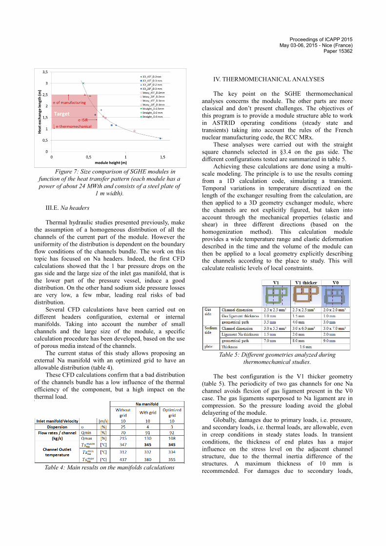
These correlations provide several thermal hydraulic
designs of the SGHE modules (figure 7) taking into account the specifications of the component, especially thermal efficiency and pressure drops (table 1). They confirm that the highest thermal compactness is obtained using 3D channels.
Concerning the ASTRID SGHE, and the associated design options, it is interesting to choose heat transfer patterns that would allow a higher thermal compactness. In this case, are selected (Figure 7) (i) straight square channel with a side of 2.5 mm as the reference solution (lowest project risk), (ii) 3D channel with a 3 mm side channels and a corrugated angle of 20 °, allowing a significant gain on module length (> 40%), regardless of the margins due to the underestimation of the heat transfer coefficient (table 2).
Proceedings of ICAPP 2015 May 03-06, 2015 - Nice (France)
Paper 15362
Figure 7: Size comparison of SGHE modules in
function of the heat transfer pattern (each module has a
power of about 24 MWth and consists of a steel plate of
1 m width). III.E. Na headers Thermal hydraulic studies presented previously, make
the assumption of a homogeneous distribution of all the
channels of the current part of the module. However the
uniformity of the distribution is dependent on the boundary
flow conditions of the channels bundle. The work on this
topic has focused on Na headers. Indeed, the first CFD
calculations showed that the 1 bar pressure drops on the
gas side and the large size of the inlet gas manifold, that is
the lower part of the pressure vessel, induce a good
distribution. On the other hand sodium side pressure losses
are very low, a few mbar, leading real risks of bad
distribution. Several CFD calculations have been carried out on
different headers configuration, external or internal
manifolds. Taking into account the number of small
channels and the large size of the module, a specific
calculation procedure has been developed, based on the use
of porous media instead of the channels. The current status of this study allows proposing an
external Na manifold with an optimized grid to have an
allowable distribution (table 4). These CFD calculations confirm that a bad distribution
of the channels bundle has a low influence of the thermal
efficiency of the component, but a high impact on the
thermal load.
Table 4: Main results on the manifolds calculations
IV. THERMOMECHANICAL ANALYSES The key point on the SGHE thermomechanical
analyses concerns the module. The other parts are more
classical and don’t present challenges. The objectives of
this program is to provide a module structure able to work
in ASTRID operating conditions (steady state and
transients) taking into account the rules of the French
nuclear manufacturing code, the RCC MRx. These analyses were carried out with the straight
square channels selected in §3.4 on the gas side. The
different configurations tested are summarized in table 5. Achieving these calculations are done using a multi-
scale modeling. The principle is to use the results coming
from a 1D calculation code, simulating a transient.
Temporal variations in temperature discretized on the
length of the exchanger resulting from the calculation, are
then applied to a 3D geometry exchanger module, where
the channels are not explicitly figured, but taken into
account through the mechanical properties (elastic and
shear) in three different directions (based on the
homogenization method). This calculation module
provides a wide temperature range and elastic deformation
described in the time and the volume of the module can
then be applied to a local geometry explicitly describing
the channels according to the place to study. This will
calculate realistic levels of local constraints.
Table 5: Different geometries analyzed during
thermomechanical studies. The best configuration is the V1 thicker geometry
(table 5). The periodicity of two gas channels for one Na
channel avoids flexion of gas ligament present in the V0
case. The gas ligaments superposed to Na ligament are in
compression. So the pressure loading avoid the global
delayering of the module. Globally, damages due to primary loads, i.e. pressure,
and secondary loads, i.e. thermal loads, are allowable, even
in creep conditions in steady states loads. In transient
conditions, the thickness of end plates has a major
influence on the stress level on the adjacent channel
structure, due to the thermal inertia difference of the
structures. A maximum thickness of 10 mm is
recommended. For damages due to secondary loads,
Proceedings of ICAPP 2015 May 03-06, 2015 - Nice (France)
Paper 15362
progressive deformation criteria in creep situation are the
most difficult to be respected. Fatigue – creep for the
considered transitory is not dimensioning and leaves wide
margins for other cycles envisaged during the lifetime. Additional studies will have to be carried out with
realistic manifold geometry, and realistic thermal loads
which take into account the not ideal distribution of the Na
channels, as defined in §3.5. V. MANUFACTURING PROCESS In order to achieve highly resistant modules, the stack
of plates must be joined at its periphery but also at its
center. Only brazing and diffusion welding can achieve
this. Brazing has been discarded in order to avoid brittle
compounds in the joints and to avoid contamination of the
base material by foreign elements which could impair its
properties, for example corrosion resistance under Na
environment. For the same reason, homogeneous diffusion
welding has been chosen, i.e. no coating (sometimes used
as an aid to diffusion welding) has been applied. Due to the
large size of the modules and the unavailability of large
uniaxial presses, diffusion welding by Hot Isostatic
Pressing (HIP) has been chosen. The plates are grooved,
cleaned and stacked in a canister. After vacuum outgassing,
the canister is sealed and HIP’ed. During HIP, creep and
diffusion enable the welding of the plates but channels may
deform. The extent of welding and deformation depends on
the HIP cycle parameters (pressure, temperature, time). The performance of the heat exchanger modules relies
on three main items: the achievement of expected channel
dimensions, the performances of the material, the
resistance of the joints. In other words, the development of
the manufacturing process aims at providing answers to the
following questions: (i) how to minimize the channel
deformation, (ii) does the process modify the base metal
and if yes, which properties are affected and how much?
(iii) how to achieve joints with properties close or identical
to base metal? The experimental development has allowed
to identify and solve many issues linked to these questions.
The reference material for the application is a 316L steel
grade with controlled addition of nitrogen and controlled
impurities but it is not available as sheets. We used 1.4404
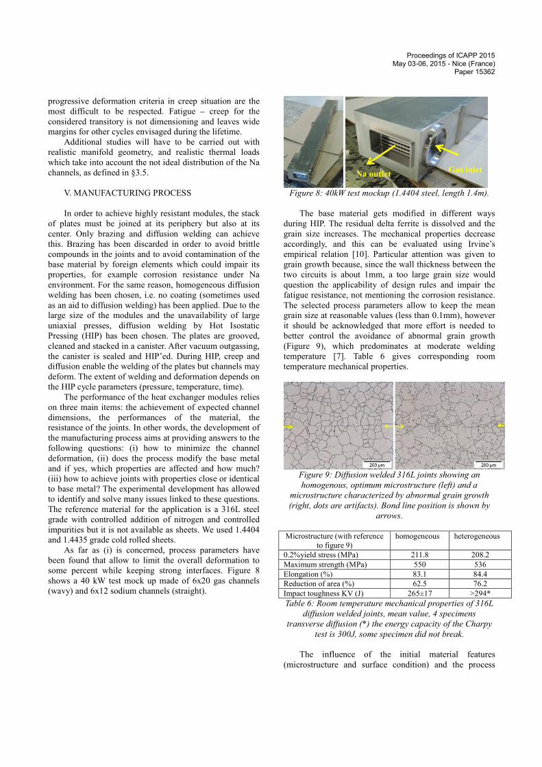
and 1.4435 grade cold rolled sheets. As far as (i) is concerned, process parameters have
been found that allow to limit the overall deformation to
some percent while keeping strong interfaces. Figure 8
shows a 40 kW test mock up made of 6x20 gas channels
(wavy) and 6x12 sodium channels (straight).
Figure 8: 40kW test mockup (1.4404 steel, length 1.4m).
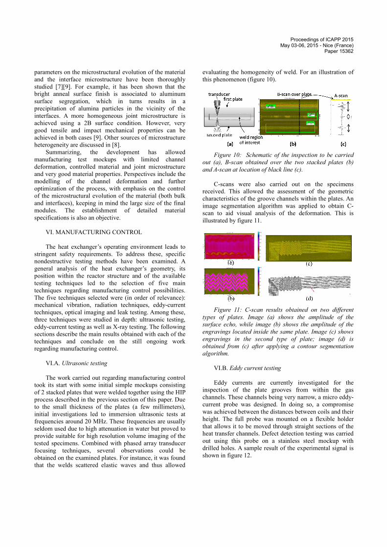
The base material gets modified in different ways
during HIP. The residual delta ferrite is dissolved and the
grain size increases. The mechanical properties decrease
accordingly, and this can be evaluated using Irvine’s
empirical relation [10]. Particular attention was given to
grain growth because, since the wall thickness between the
two circuits is about 1mm, a too large grain size would
question the applicability of design rules and impair the
fatigue resistance, not mentioning the corrosion resistance.
The selected process parameters allow to keep the mean
grain size at reasonable values (less than 0.1mm), however
it should be acknowledged that more effort is needed to
better control the avoidance of abnormal grain growth
(Figure 9), which predominates at moderate welding
temperature [7]. Table 6 gives corresponding room
temperature mechanical properties.
Figure 9: Diffusion welded 316L joints showing an
homogenous, optimum microstructure (left) and a
microstructure characterized by abnormal grain growth
(right, dots are artifacts). Bond line position is shown by
arrows.
Microstructure (with reference
to figure 9) homogeneous heterogeneous
0.2%yield stress (MPa) 211.8 208.2 Maximum strength (MPa) 550 536 Elongation (%) 83.1 84.4 Reduction of area (%) 62.5 76.2 Impact toughness KV (J) 265±17 >294* Table 6: Room temperature mechanical properties of 316L
diffusion welded joints, mean value, 4 specimens
transverse diffusion (*) the energy capacity of the Charpy
test is 300J, some specimen did not break. The influence of the initial material features
(microstructure and surface condition) and the process
Na outlet Gas inlet
Proceedings of ICAPP 2015 May 03-06, 2015 - Nice (France)
Paper 15362
parameters on the microstructural evolution of the material
and the interface microstructure have been thoroughly
studied [7][9]. For example, it has been shown that the
bright anneal surface finish is associated to aluminum
surface segregation, which in turns results in a
precipitation of alumina particles in the vicinity of the
interfaces. A more homogeneous joint microstructure is
achieved using a 2B surface condition. However, very
good tensile and impact mechanical properties can be
achieved in both cases [9]. Other sources of microstructure
heterogeneity are discussed in [8]. Summarizing, the development has allowed
manufacturing test mockups with limited channel
deformation, controlled material and joint microstructure
and very good material properties. Perspectives include the
modelling of the channel deformation and further
optimization of the process, with emphasis on the control
of the microstructural evolution of the material (both bulk
and interfaces), keeping in mind the large size of the final
modules. The establishment of detailed material
specifications is also an objective. VI. MANUFACTURING CONTROL The heat exchanger’s operating environment leads to
stringent safety requirements. To address these, specific
nondestructive testing methods have been examined. A
general analysis of the heat exchanger’s geometry, its
position within the reactor structure and of the available
testing techniques led to the selection of five main
techniques regarding manufacturing control possibilities.
The five techniques selected were (in order of relevance):
mechanical vibration, radiation techniques, eddy-current
techniques, optical imaging and leak testing. Among these,
three techniques were studied in depth: ultrasonic testing,
eddy-current testing as well as X-ray testing. The following
sections describe the main results obtained with each of the
techniques and conclude on the still ongoing work
regarding manufacturing control. VI.A. Ultrasonic testing The work carried out regarding manufacturing control
took its start with some initial simple mockups consisting
of 2 stacked plates that were welded together using the HIP
process described in the previous section of this paper. Due
to the small thickness of the plates (a few millimeters),
initial investigations led to immersion ultrasonic tests at
frequencies around 20 MHz. These frequencies are usually
seldom used due to high attenuation in water but proved to
provide suitable for high resolution volume imaging of the
tested specimens. Combined with phased array transducer
focusing techniques, several observations could be
obtained on the examined plates. For instance, it was found
that the welds scattered elastic waves and thus allowed
evaluating the homogeneity of weld. For an illustration of
this phenomenon (figure 10).
Figure 10: Schematic of the inspection to be carried
out (a), B-scan obtained over the two stacked plates (b)
and A-scan at location of black line (c). C-scans were also carried out on the specimens
received. This allowed the assessment of the geometric
characteristics of the groove channels within the plates. An
image segmentation algorithm was applied to obtain C-scan to aid visual analysis of the deformation. This is
illustrated by figure 11.
Figure 11: C-scan results obtained on two different
types of plates. Image (a) shows the amplitude of the
surface echo, while image (b) shows the amplitude of the
engravings located inside the same plate. Image (c) shows
engravings in the second type of plate; image (d) is
obtained from (c) after applying a contour segmentation
algorithm. VI.B. Eddy current testing Eddy currents are currently investigated for the
inspection of the plate grooves from within the gas
channels. These channels being very narrow, a micro eddy-current probe was designed. In doing so, a compromise
was achieved between the distances between coils and their
height. The full probe was mounted on a flexible holder
that allows it to be moved through straight sections of the
heat transfer channels. Defect detection testing was carried
out using this probe on a stainless steel mockup with
drilled holes. A sample result of the experimental signal is
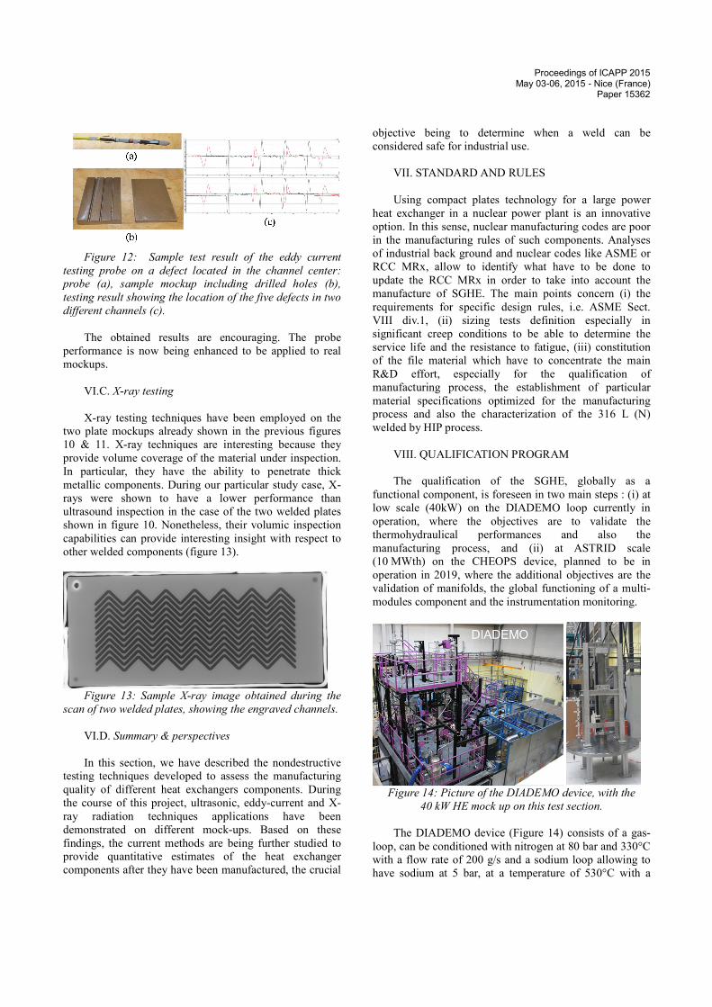
shown in figure 12.
Proceedings of ICAPP 2015 May 03-06, 2015 - Nice (France)
Paper 15362
Figure 12: Sample test result of the eddy current
testing probe on a defect located in the channel center:
probe (a), sample mockup including drilled holes (b),
testing result showing the location of the five defects in two
different channels (c). The obtained results are encouraging. The probe
performance is now being enhanced to be applied to real
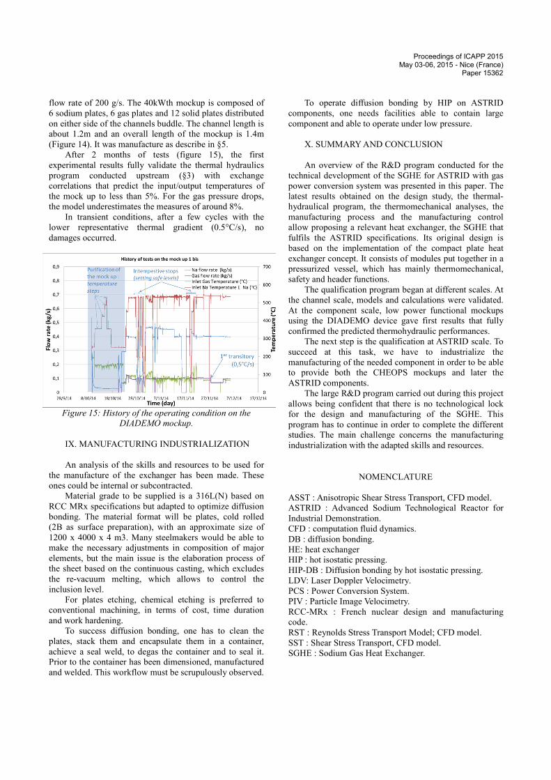
mockups. VI.C. X-ray testing X-ray testing techniques have been employed on the
two plate mockups already shown in the previous figures
10 & 11. X-ray techniques are interesting because they
provide volume coverage of the material under inspection.
In particular, they have the ability to penetrate thick
metallic components. During our particular study case, X-rays were shown to have a lower performance than
ultrasound inspection in the case of the two welded plates
shown in figure 10. Nonetheless, their volumic inspection
capabilities can provide interesting insight with respect to
other welded components (figure 13).
Figure 13: Sample X-ray image obtained during the
scan of two welded plates, showing the engraved channels. VI.D. Summary & perspectives In this section, we have described the nondestructive
testing techniques developed to assess the manufacturing
quality of different heat exchangers components. During
the course of this project, ultrasonic, eddy-current and X-ray radiation techniques applications have been
demonstrated on different mock-ups. Based on these
findings, the current methods are being further studied to
provide quantitative estimates of the heat exchanger
components after they have been manufactured, the crucial
objective being to determine when a weld can be
considered safe for industrial use. VII. STANDARD AND RULES Using compact plates technology for a large power
heat exchanger in a nuclear power plant is an innovative
option. In this sense, nuclear manufacturing codes are poor
in the manufacturing rules of such components. Analyses
of industrial back ground and nuclear codes like ASME or
RCC MRx, allow to identify what have to be done to
update the RCC MRx in order to take into account the
manufacture of SGHE. The main points concern (i) the
requirements for specific design rules, i.e. ASME Sect.
VIII div.1, (ii) sizing tests definition especially in
significant creep conditions to be able to determine the
service life and the resistance to fatigue, (iii) constitution
of the file material which have to concentrate the main
R&D effort, especially for the qualification of
manufacturing process, the establishment of particular
material specifications optimized for the manufacturing
process and also the characterization of the 316 L (N)
welded by HIP process. VIII. QUALIFICATION PROGRAM The qualification of the SGHE, globally as a
functional component, is foreseen in two main steps : (i) at
low scale (40kW) on the DIADEMO loop currently in
operation, where the objectives are to validate the
thermohydraulical performances and also the
manufacturing process, and (ii) at ASTRID scale
(10 MWth) on the CHEOPS device, planned to be in
operation in 2019, where the additional objectives are the
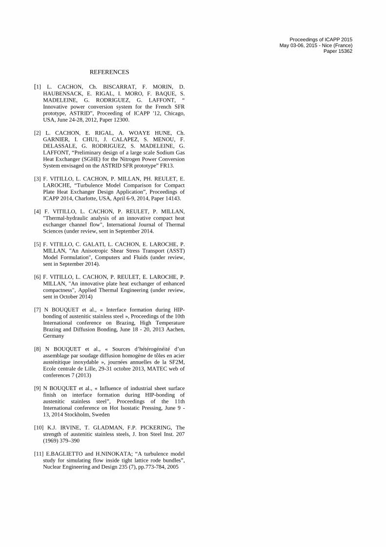
validation of manifolds, the global functioning of a multi-modules component and the instrumentation monitoring.
Figure 14: Picture of the DIADEMO device, with the
40 kW HE mock up on this test section. The DIADEMO device (Figure 14) consists of a gas-
loop, can be conditioned with nitrogen at 80 bar and 330°C
with a flow rate of 200 g/s and a sodium loop allowing to
have sodium at 5 bar, at a temperature of 530°C with a
Proceedings of ICAPP 2015 May 03-06, 2015 - Nice (France)
Paper 15362
flow rate of 200 g/s. The 40kWth mockup is composed of
6 sodium plates, 6 gas plates and 12 solid plates distributed
on either side of the channels buddle. The channel length is
about 1.2m and an overall length of the mockup is 1.4m
(Figure 14). It was manufacture as describe in §5. After 2 months of tests (figure 15), the first
experimental results fully validate the thermal hydraulics
program conducted upstream (§3) with exchange
correlations that predict the input/output temperatures of
the mock up to less than 5%. For the gas pressure drops,
the model underestimates the measures of around 8%. In transient conditions, after a few cycles with the
lower representative thermal gradient (0.5°C/s), no
damages occurred.
Figure 15: History of the operating condition on the
DIADEMO mockup. IX. MANUFACTURING INDUSTRIALIZATION An analysis of the skills and resources to be used for
the manufacture of the exchanger has been made. These
ones could be internal or subcontracted. Material grade to be supplied is a 316L(N) based on
RCC MRx specifications but adapted to optimize diffusion
bonding. The material format will be plates, cold rolled
(2B as surface preparation), with an approximate size of
1200 x 4000 x 4 m3. Many steelmakers would be able to
make the necessary adjustments in composition of major
elements, but the main issue is the elaboration process of
the sheet based on the continuous casting, which excludes
the re-vacuum melting, which allows to control the
inclusion level. For plates etching, chemical etching is preferred to
conventional machining, in terms of cost, time duration
and work hardening. To success diffusion bonding, one has to clean the
plates, stack them and encapsulate them in a container,
achieve a seal weld, to degas the container and to seal it.
Prior to the container has been dimensioned, manufactured
and welded. This workflow must be scrupulously observed.
To operate diffusion bonding by HIP on ASTRID
components, one needs facilities able to contain large
component and able to operate under low pressure. X. SUMMARY AND CONCLUSION An overview of the R&D program conducted for the
technical development of the SGHE for ASTRID with gas
power conversion system was presented in this paper. The
latest results obtained on the design study, the thermal-hydraulical program, the thermomechanical analyses, the
manufacturing process and the manufacturing control
allow proposing a relevant heat exchanger, the SGHE that
fulfils the ASTRID specifications. Its original design is
based on the implementation of the compact plate heat
exchanger concept. It consists of modules put together in a
pressurized vessel, which has mainly thermomechanical,
safety and header functions. The qualification program began at different scales. At
the channel scale, models and calculations were validated.
At the component scale, low power functional mockups
using the DIADEMO device gave first results that fully
confirmed the predicted thermohydraulic performances. The next step is the qualification at ASTRID scale. To
succeed at this task, we have to industrialize the
manufacturing of the needed component in order to be able
to provide both the CHEOPS mockups and later the
ASTRID components. The large R&D program carried out during this project
allows being confident that there is no technological lock
for the design and manufacturing of the SGHE. This
program has to continue in order to complete the different
studies. The main challenge concerns the manufacturing
industrialization with the adapted skills and resources.
NOMENCLATURE
ASST : Anisotropic Shear Stress Transport, CFD model. ASTRID : Advanced Sodium Technological Reactor for
Industrial Demonstration. CFD : computation fluid dynamics. DB : diffusion bonding. HE: heat exchanger HIP : hot isostatic pressing. HIP-DB : Diffusion bonding by hot isostatic pressing. LDV: Laser Doppler Velocimetry. PCS : Power Conversion System. PIV : Particle Image Velocimetry. RCC-MRx : French nuclear design and manufacturing
code. RST : Reynolds Stress Transport Model; CFD model. SST : Shear Stress Transport, CFD model. SGHE : Sodium Gas Heat Exchanger.
Proceedings of ICAPP 2015 May 03-06, 2015 - Nice (France)
Paper 15362
REFERENCES
[1] L. CACHON, Ch. BISCARRAT, F. MORIN, D. HAUBENSACK, E. RIGAL, I. MORO, F. BAQUE, S. MADELEINE, G. RODRIGUEZ, G. LAFFONT, “ Innovative power conversion system for the French SFR prototype, ASTRID”, Proceeding of ICAPP '12, Chicago, USA, June 24-28, 2012, Paper 12300.
[2] L. CACHON, E. RIGAL, A. WOAYE HUNE, Ch.
GARNIER, I. CHU1, J. CALAPEZ, S. MENOU, F. DELASSALE, G. RODRIGUEZ, S. MADELEINE, G. LAFFONT, “Preliminary design of a large scale Sodium Gas Heat Exchanger (SGHE) for the Nitrogen Power Conversion System envisaged on the ASTRID SFR prototype” FR13.
[3] F. VITILLO, L. CACHON, P. MILLAN, PH. REULET, E.
LAROCHE, “Turbulence Model Comparison for Compact Plate Heat Exchanger Design Application”, Proceedings of ICAPP 2014, Charlotte, USA, April 6-9, 2014, Paper 14143.
[4] F. VITILLO, L. CACHON, P. REULET, P. MILLAN,
"Thermal-hydraulic analysis of an innovative compact heat exchanger channel flow", International Journal of Thermal Sciences (under review, sent in September 2014.
[5] F. VITILLO, C. GALATI, L. CACHON, E. LAROCHE, P.
MILLAN, "An Anisotropic Shear Stress Transport (ASST) Model Formulation", Computers and Fluids (under review, sent in September 2014).
[6] F. VITILLO, L. CACHON, P. REULET, E. LAROCHE, P.
MILLAN, "An innovative plate heat exchanger of enhanced compactness", Applied Thermal Engineering (under review, sent in October 2014)
[7] N BOUQUET et al., « Interface formation during HIP-
bonding of austenitic stainless steel », Proceedings of the 10th International conference on Brazing, High Temperature Brazing and Diffusion Bonding, June 18 - 20, 2013 Aachen, Germany
[8] N BOUQUET et al., « Sources d’hétérogénéité d’un
assemblage par soudage diffusion homogène de tôles en acier austénitique inoxydable », journées annuelles de la SF2M, Ecole centrale de Lille, 29-31 octobre 2013, MATEC web of conferences 7 (2013)
[9] N BOUQUET et al., « Influence of industrial sheet surface
finish on interface formation during HIP-bonding of austenitic stainless steel”, Proceedings of the 11th International conference on Hot Isostatic Pressing, June 9 - 13, 2014 Stockholm, Sweden
[10] K.J. IRVINE, T. GLADMAN, F.P. PICKERING, The
strength of austenitic stainless steels, J. Iron Steel Inst. 207 (1969) 379–390
[11] E.BAGLIETTO and H.NINOKATA; “A turbulence model
study for simulating flow inside tight lattice rode bundles”, Nuclear Engineering and Design 235 (7), pp.773-784, 2005


![Sodium Phytate Presentation.pptx [Read-Only]formulatorsampleshop.com/v/reference/Sodium Phytate Presentation.pdfLaurate (Skin Conditioning Agent), Sodium Benzoate (Preservative), Sodium](https://img.pdfslide.net/doc/110x75/5eb52012fb0f3e0d55767ea6/sodium-phytate-read-onlyformulatorsampleshopcomvreferencesodium-phytate-presentationpdf.jpg)