Embed Size (px)
Citation preview

Steady State and Dynamic Modelling of Residential Transpired Solar Collectors Performance
Emmanouil Perisoglou1, Ester Coma Bassas1, Simon Lannon1, Xiaojun Li1, Huw Jenkins1, Joanne
Patterson1, Philip Jones1, Shan Hou1
Welsh School of Architecture, Cardiff University, Cardiff, UK
Abstract
This paper introduces a methodology for the integration
of the Transpired Solar Collector (TSC) technology into
the Standard Assessment Procedure (SAP). The
challenges addressed by this work include the
demonstration of the integration of a dynamic low-energy
device into an inflexible steady state calculation method.
Two innovative techniques are introduced and their use
depend on how the TSC is connected to the buildings’
mechanical ventilation with heat recovery (MVHR)
system. A case study demonstrates the effectiveness of the
methodology as the model’s results are compared against
extensive monitoring data and other data-adjusted
dynamic modelling. The results indicate that the
application of the TSC to a UK detached house reduces
the heat demand by 1000kWh in a heating season.
Moreover, when connected to a heat recovery unit the
benefit is not cumulative, yet it still reduces the heat
demand by approximately 300kWh.
Introduction
Installation of innovative technologies in the domestic
sector is a challenging process as there are great
expectations from an immature market. In addition to
reliable installation, warranties, maintenance and robust
commissioning protocols, the market is expected to
provide credible prediction tools. Also, the Governmental
supporting mechanisms demand evidence and evaluation
tools to adopt and enhance new technologies. For these
reasons, continuous commissioning is a vital process in
order to fill the performance gap, educate modelling tools
and feedback to both market and occupants (Jradi et al.,
2018).
What is a TSC
Transpired Solar Collectors (TSCs) have been used to
help reduce building energy consumption for over 30
years (Brown et al., 2014, Shukla et al., 2012). TSCs
consist of perforated cladding panels which are installed
on the southerly façade or roof of a building, separated
from the building envelope by a cavity. As the collector
absorbs solar radiation, its surface becomes warmed and
a fan draws the surface air into the cavity through the
perforations. The heated air can then be directly
distributed into a building through a mechanical
ventilation system or ducted into an air heating system
such as a heat pump.
Domestic TSCs limitations and opportunities
Previous research in the UK has found that TSCs can
contribute approximately 20% of the building’s heating
demand with a payback of 2 to 10 years (Hall et al., 2011).
The National Renewable Energy Laboratory in US
indicates lifespan of 30+ years and claims an installation
cost of approximately £50/m2 for new construction and
£100/m2 for retrofit applications (NREL, 2000). Data
collection from UK commercial sites support market
claims stating that the system can deliver from 200 to
300kWh/m2/year for a volume flow rate between 50 and
150m3/hr/m2TSC (TATA steel, 2017, Pearson, 2007,
Brewster, 2010). TSC Installation in residential buildings
or individual dwellings have been relatively uncommon
due to the rarity of domestic mechanical ventilation
systems and the mismatch between the heat demand and
TSC solar based generation. However, there is an
increased demand for air tight houses and improved air
quality which has led to controlled 24/7 fresh air
requirement (Maier et al., 2009, Zero Carbon HUB,
2013). Mechanical ventilation is becoming well-accepted
in the residential construction market (Evola et al., 2017);
however, there are still challenges to be addressed such as
noise, supply-delivery balance, drafts, increased heat
demand and cost (Gupta et al., 2015). Heat exchangers
reduce the additional heating demand caused by the fresh
air delivery of the mechanical ventilation systems.
Furthermore, small aesthetically pleasing TSCs can
preheat the required fresh air and reduce the house heat
demand still further. However, the TSC delivers a
proportion of the heat that would be provided by the heat
exchanger of the MVHR, which is a drawback of
combining the systems. This paper attempts to explore
and quantify this impact.
Monitoring – Evaluation of TSCs
The performance of a TSC depends on a wide variety of
parameters such as climatic conditions, size, absorptivity,
building aspect, perforation pattern and air flow rates
(Shukla et al., 2012). The design of the TSC panel, the
spacing of the holes and size of the cavity is well
understood and optimised by using the TSC efficiency
equation which indicates the percentage of solar radiation
transformed into heat. In this study, commercial
optimised “anthracite” coloured TSC panels were used in
a UK house and the fundamental performance indicator is
the heat delivery.
Proceedings of BSO 2018: 4th Building Simulation and Optimization Conference, Cambridge, UK: 11-12 September 2018
223

In the case study, the supply from the TSC is connected
by ductwork to a Heat Exchanger (HE). The heat transfer
across the heat exchanger was monitored and the impact
of the TSC preheat on the performance of the MVHR’s
heat exchanger was investigated and integrated into the
SAP (Standard Assessment Procedure) model.
TSC Simulations and SAP
Swift, developed by Enermodal Engineering, is a
simulation tool specialised in TSC performance
prediction, based on empirical models (Natural Resourses
Canada, 2017). It can be adjusted by monitored data and
includes a broad spectrum of parametrisation. It has been
used to validate other models such as RETScreen
(Canadian Government) and SBET (Sustainable Building
Estimation Tool for TATA steel).
HTB2 is a dynamic simulation tool for the energy and
environmental performance of buildings from Cardiff
University (Sat and Yik, 2003). It is not a TSC
performance evaluation tool, however it can simulate the
collector as a heat gain from an external wall by using heat
transfer parameters.
SAP (Standard Assessment Procedure) is the UK
government approved system for assessing the energy
rating of dwellings. It is a steady state national calculation
method for dwellings, however it was developed as a fast
energy rating tool and not a building performance tool.
This simplification in building’s physics raises a seiries of
uncertainties and errors discussed in both industrial and
institutional level (Martin and Sheldrick, 2015, Kelly et
al., 2012). There is little research in the integration of solar
thermal technologies into SAP and it is limited to hot
water technologies (Murphy et al., 2011, O’Hegarty et al.,
2014). SAP is not a sizing tool and it does not include a
full spectrum of building integrated renewables such as
TSCs. The UK national calulation method for non-
domestic buildings, SBEM (Simplified Building Energy
Model), includes TSC calulations in non-domestic
buildings (IES, 2014), however it does not study TSCs in
conjuction to an MVHR.
Abbreviations – Nomenclature
HE Heat exchanger (commonly in an MVHR)
LCRI Low Carbon Research Institute
MVHR Mechanical Ventilation with Heat Recovery
SAP Standard Assessment Procedure
SBEM Simplified Building Energy Model
SBET Sustainable Building Estimation Tool
SOLCER Smart Operation for Low Carbon Energy Region
TSC Transpired Solar Collector
UK United Kingdom
WEFO Welsh European Funding Office
Cp Specific heat of air (1.007 to 1.048 kJ/kg.K at 1 atm)
m Air mass flow rate (kg/s)
ηΗΕ or η Heat exchanger – recovery efficiency in SAP
ηTSC TSC efficiency
η’ Combined TSC+HE efficiency
Tamb Air temperature external – ambient (K or oC)
Tdel Air temperature delivered after the HE (K or oC)
Texh Air temperature exhaust from the HE (K or oC)
Text Air temperature from extract ducts (K or oC)
Trise Air temperature rise (K or oC)
TTSC Air temperature after the collector – delivery (K or oC)
T’del Air temperature delivered after the TSC+HE (K or oC)
T’exh Air temperature exhaust from the TSC+HE (K or oC)
QdelHE Heat exchanger heat delivery (W)
QdelHE’ Heat exchanger heat delivery affected by the TSC (W)
QdelTSC TSC heat delivery (W)
QdelTSC+HE’ Total Heat delivery by the TSC and the heat exchanger (W)
224

This study demostrates the development of two simple
approaches for integrating the TSC into the national
calculation model. The first method is similar to the HTB2
model for TSC integration into SAP, and the second is an
innovative approach for HE+TSC modelling in SAP by
introducing a new combined efficiency. In addition, this
paper validates the SAP TSC results by using HTB2,
SWIFT and monitoring data.
Experiment
TSC Monitoring as a system response indicator and
modelling validator
The extensive monitoring used in this study was an
essential instrument in order to understand the
performance of the collector and its ductwork in response
to the weather and demand profiles. Also, monitoring
enabled the interaction between the TSC and MVHR
systems to be quantified. Furthermore, the dynamic
modelling tool (HTB2) was informed by monitored local
weather, real-life demand data and most importantly by
variable mass flow rates and temperature rises in response
to the heat transfer equation (1). Averaged monitoring
parameters informed and optimised the steady state
modelling tools (SAP and Swift) and their prediction (heat
delivery) was then compared against calculated heat
delivery from monitored data.
The effectiveness of the TSC is determined by the
ventilation and heat demand of the case study, as well as
environmental conditions, size, inclination and
orientation. The heat delivery (QdelTSC) of the TSC is
calculated using the fundamental equation for fluid heat
transfer.
QdelTSC = m Cp Trise = m Cp (TTSC-Tamb) (1)
where m is the air mass flow rate, Cp is the specific heat
of air and Trise is the temperature difference between the
ambient (Tamb) and the duct air after the collector (TTSC).
The monitoring methodology at the demonstration house
was based on the Perisoglou and Dixon study on TSCs
(Perisoglou and Dixon, 2015).
High accuracy temperature sensors (4 wires, PT 100 class
A) measured the ambient outside and supply air
temperature. Also, multipoint, high accuracy, low
differential pressure probes were placed in the delivery
and exhaust duct to calculate the mass flow rate. The data
collection time interval was set to 5 minutes to record
transient conditions.
Case study – TSC in Solcer house
The SOLCER House demonstrator was built as part of the
Cardiff University-led Low Carbon Research Institute
project (LCRI) and funded by the European Regional
Development Fund through WEFO to enable Wales and
its industry partners to lead the way in research to cut
carbon emissions. A condition of the funding body was
that the building could not be for domestic use;
consequently the SOLCER House was occupied as a test
facility with daily office-type user profiles (see figure 1
left). To minimise heating energy demand, a fabric
approach was used with very high levels of insulation in
walls, roofs and floors, and very high-performance
windows.
A south-facing 13.8m2 vertical TSC has been installed as
a preheater for a combined exhaust air to air space heating
and hot water heat pump. Before the heat pump the
incoming air passes through a balanced MVHR system
with a heat exchanger between the outgoing and incoming
air. In this study, only the TSC and MVHR are studied as
a preheating stage to the heat pump.
Figure 1: Solcer House, Bridgend, Wales (latit. 51.5o).
Left: TSC located across the façade of the upper floor.
Right: Detail of the metal cladding/ perforation.
Experimental Methodology and Results
The heat demand of the house and the heat contribution of
the TSC and the MVHR were modelled using different
tools and also measured for a duration of one year (July
’16 to June ’17). The dynamic modelling tool used was
HTB2 informed by hourly monitored occupancy patterns
and monthly averaged flow rates and weather data. SAP
and SWIFT were also informed by monthly averaged
monitored weather data and annually averaged monitored
flow rates. All models used the same weather file
informed by monitoring data collected by a weather
station on site. The building parameters were verified or
corrected by in-situ testing. Fundamental parameter
inputs can be found in the following table (Table 1).
Table 1: Solcer house fabric and system parameters.
Main Parameters Values Units
Floor area -Ground Floor 51.8 m2
Floor area - First floor 51.8 m2
External wall area - Gross 148.4 m2
External wall area - Openings 15.4 m2
External wall - U value 0.12 W/m2K
Roof - U value 0.15 W/m2K
Floor - U value 0.15 W/m2K
Pressure test 3.0 m3/h.m2@50Pa
Summer Bypass 25 oC
TSC area 13.8 m2
TSC Cavity depth 0.3 m
Aver. TSC annual supply flow rate 165 m3/h
Heat recovery rate (ηΗΕ),
manufacturer PHPP certificate
76 %
225

As SAP is not able to directly calculate the impact of a
TSC, the first approach proposed in this study is to
simulate the TSC as an external wall with heat gains
similar to the heat delivery from a TSC. This method
requires TSC efficiency (ηTSC) and area input as well as a
weather file with solar radiation corresponding to the
inclination and orientation of the collector. The ηTSC and
the vertical solar radiation falling to the collector were
calculated using monitoring data and were fed into the
SAP model.
When the house is equipped with an MVHR, this method
is insufficient as there is an interaction between the TSC
and the MVHR’s heat exchanger which is investigated
and quantified below. For SAP modelling of HE+TSC
system, this paper suggests that the TSC could be treated
as a preheat to the MVHR and for this reason it introduces
a second method by using a new combined efficiency for
the HE+TSC system (η’) in order to replace the HE
efficiency in SAP (η). This method is described below:
i. SAP models the impact of the MVHR to the heat
demand of a building by including the Specific Fan
Power (SFP), the heat exchanger efficiency and
ducting information to the calculations (BRE, 2011).
The heat exchanger’s efficiency (η), also used by
manufacturers, could be calculated by using measured
temperature data (2).
𝜂 =𝑇𝑑𝑒𝑙−𝑇𝑎𝑚𝑏
𝑇𝑒𝑥𝑡−𝑇𝑎𝑚𝑏 (2)
where Tdel is the temperature delivered to the building
after the heat exchanger. Tamb is the input temperature
coming from the ambient fresh air. Text is the resultant
air temperature from all of the dwelling’s extract ducts
(Figure 2).
Figure 2: Heat Exchanger of the MVHR.
ii. Heat transfer equation also applies for the heat
exchanger which delivers heat:
QdelHE = m Cp (Tdel-Tamb) (3)
iii. When a TSC is added, the heat exchanger will get a
new input temperature (TTSC) which will change the
HE delivered temperature (T’del) and the exhaust
temperature (T’exh) as shown in figure 3A. The TSC
can be represented as an additional preheating device
to the heat exchanger. The new system (HE+TSC
system) will, in combination, deliver heat according to
the equation for fluid heat transfer:
QdelTSC+HE’ = QdelTSC + QdelHE’ = m Cp (T’del-Tamb) =
m Cp (TTSC-Tamb) + m Cp (T’del-TTSC) (4)
Figure 3: Heat Exchanger with the TSC as a system.
Combined view 3A and Heat exchanger focus 3B.
iv. The SAP model cannot adopt heat delivery equations;
however, it allows for the user to adjust the heat
exchanger efficiency which can now be called
system’s efficiency (η’) for combined HE+TSC.
𝜂′ =𝑇′𝑑𝑒𝑙−𝑇𝑎𝑚𝑏
𝑇𝑒𝑥𝑡−𝑇𝑎𝑚𝑏 (5)
v. Meanwhile, the heat exchanger efficiency (η) equation
still describes the physics of the dark grey box in
figure 3B where the new delivery temperature (T’del)
is affected by the new TSC delivered temperature
(TTSC):
𝜂 =𝑇𝑑𝑒𝑙−𝑇𝑎𝑚𝑏
𝑇𝑒𝑥𝑡−𝑇𝑎𝑚𝑏=
𝑇′𝑑𝑒𝑙−𝑇𝑇𝑆𝐶
𝑇𝑒𝑥𝑡−𝑇𝑇𝑆𝐶 (6)
𝑇′𝑑𝑒𝑙 = 𝜂(𝑇𝑒𝑥𝑡 − 𝑇𝑇𝑆𝐶) + 𝑇𝑇𝑆𝐶
= 𝜂𝑇𝑒𝑥𝑡 + (1 − 𝜂)𝑇𝑇𝑆𝐶 (7)
vi. Which means that equation (5) can be transformed to:
𝜂′ =𝜂𝑇𝑒𝑥𝑡+(1−𝜂)𝑇𝑇𝑆𝐶−𝑇𝑎𝑚𝑏
𝑇𝑒𝑥𝑡−𝑇𝑎𝑚𝑏 (8)
This last equation shows that the new HE+TSC efficiency
(η’) is only depended on the exchanger’s efficiency (η),
the input temperature (Tamb) and the TSC delivered
temperature (Text) which is subject to the TSC
characteristics and weather conditions.
The following diagram (Figure 4) summarises the
methodology followed in order to calculate or model the
heat delivery of the HE, the TSC and the combined
HE+TSC. SWIFT methodology is not included as it was
only used to model the TSC gains.
The MVHR’s heat exchanger’s efficiency (η) and the
HE+TSC efficiency (η’) were calculated by using
monitored data in equations (5) and (6). The efficiency (η)
was calculated at 75.5% which is very close to the
manufacturers HE η at 76% stated in PHPP certificate
(table 1). The new HE+TSC efficiency (η’) was calculated
at 92.2% which shows the benefit of the TSC.
By knowing the heat exchanger stand-alone efficiency (η)
in equation (2), the hypothetical MVHR delivered
temperature (Tdel) was calculated and used in equation (3)
in order to calculate the heat delivery from the MVHR as
Tamb Text
TdelTexh
H.E.
Tamb Text
T’delT’exh
H.E.
TTSC
Tamb Text
T’delT’exh
H.E.
TTSC
A B
Tamb Text
T’delT’exh
H.E.
TTSC
Tamb Text
T’delT’exh
H.E.
TTSC
A B
226
if there were no TSC. The heat delivery equation was also
used with monitored data to calculate TSC delivery and
MVHR delivery.
SAP model was informed by the new efficiencies and
used to model the heat delivery from the MVHR alone,
the TSC alone, and the MVHR+TSC system.
HTB2 modelled the MVHR heat delivery alone, the TSC
heat delivery alone, and the MVHR+TSC combined heat
delivery. All the modelling and the monitoring-based
calculations are shown in figure 5 below.
Figure 4: Modelling and monitoring methodology used to calculate the heat delivery of the MVHR assuming
no TSC, TSC and MVHR+TSC.
.
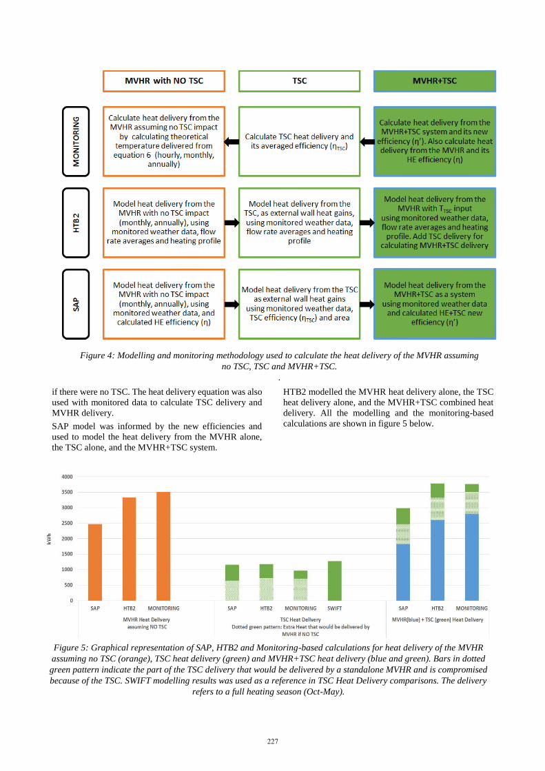
Figure 5: Graphical representation of SAP, HTB2 and Monitoring-based calculations for heat delivery of the MVHR
assuming no TSC (orange), TSC heat delivery (green) and MVHR+TSC heat delivery (blue and green). Bars in dotted
green pattern indicate the part of the TSC delivery that would be delivered by a standalone MVHR and is compromised
because of the TSC. SWIFT modelling results was used as a reference in TSC Heat Delivery comparisons. The delivery
refers to a full heating season (Oct-May).
227

Discussion
The two models and the monitoring-based calculations
were compared in figure 5. SAP’s MVHR heat delivery is
relatively low as the mass flow rate measured and used by
HTB2 is higher than the one suggested by SAP. The
reason is the usage of non-dynamic SAP flow rates and
internal temperatures.
The TSC connected to the MV or MVHR delivers the
same amount of heat. In the case study it delivered
971kWh of heat for the heating season as shown in figure
5 (green monitoring bar). TSC delivery models slightly
overestimated the heat delivery (10 to 20%). This could
be for several reasons, such as the dynamic mass flow
rate, the shape of the panel, the heat loss recirculation, or
low flow turbulence effects and further investigations are
needed.
When the TSC is connected to an MV, the final heat
delivery is not affected by the MV; however, when it is
connected to an MVHR, the benefit of the MVHR+TSC
is not cumulative. The presence of the TSC benefits the
system’s heat delivery (MVHR+TSC); however, it
compromises the heat exchanger’s potential. This means
that a stand-alone MVHR would deliver approximately an
additional 2/3 of the TSC delivery in the TSC’s absence
as shown in the dotted green patterned bars in figure 5.
This is a critical observation as in most of the cases, the
domestic mechanical ventilation is assisted by a heat
exchanger and both models and monitoring are in
agreement within 95%
Another observation is that SAP ignores the heat delivery
in summer which is not always unwanted, especially if it
is for free and the ambient air is not warm enough during
the night or a relatively cold day. In reality, the
MVHR+TSC delivered an extra 700kWh from June to
September which accounts for approximately 7% of the
annual heat demand and 20% of the MVHR+TSC annual
heat delivery.
The two proposed methodologies for integrating a TSC
into the SAP model refer to a house with a MV and a
house with MVHR.
The first methodology requires to input the TSC
efficiency and the vertical solar radiation falling to the
collector. In the case study these parameters were
calculated using monitoring data and were fed into SAP
model; however, in a prediction exercise the collector’s
efficiency could be found in the manufacturer’s
specifications and the vertical solar in an appropriate
weather database where horizontal radiation should
mathematically be converted to vertical.
The second methodology demands the new system’s
efficiency (η’) which is dependent on the exchanger’s
efficiency (η) and the ambient, extract and TSC
temperatures. In this case study temperatures were
monitored and η was calculated. In a modelling scenario,
η can be taken from the MVHR manufacturer’s specs,
ambient air from an appropriate weather database and
extract is the desired room temperature, suggested by
building regulations and guidance. The only parameter
that is hard to predetermine is the TSC delivered
temperature which is affected by seasonal weather and
demand variations, as well as TSC technical
characteristics and flow rate. Software such as Swift and
HTB2 can model a TSC and export an average monthly
TSC delivery temperature in order to be used for η’
calculations.
The heat delivered by the MVHR+TSC is greater than the
MVHR alone; the only exception is during the night when
sometimes the TSC panel could create a cooling effect on
incoming winter air. This effect could be significant for
external walls with very low heat losses and more
investigation is required.
The heat delivered by a combined MVHR+TSC system
will always be less than the sum of a stand alone TSC and
a stand alone MVHR. There are two reasons that could
explain this statement. The first is that the TSC will
compromise the MVHR as it delivers part of the heat that
the heat exchanger would deliver. The second occurs for
high TSC temperature delivery (i.e. above the extract
temperature), in this case, the MVHR would cool the
delivery air down, exchanging heat in the opposite
direction. This can be resolved by an MVHR which
includes internal heat exchange bypass.
Conclusion
This study introduces two approaches that can be used in
SAP in order to calculate the TSC heat contribution. The
first method allows SAP to model the TSC as a stand
alone system by simulating the panel as heat gains from
an external wall. In order to apply this into SAP, TSC
efficiency, area and vertical solar radiation should be
input by the user. The second method is used when the
TSC is connected to an MVHR system and allows SAP to
model the combined system as an upgraded MVHR with
a new efficiency (η’). The inputs for the second method
are the heat exchanger’s efficiency, and the averaged
ambient, extract and TSC temperatures.
The paper also investigates the interaction between a TSC
and an MVHR validated by monitored data. The
equations’ analysis and the results showed that although
the TSC is beneficial, it does not accumulatively add its
heat delivery to the MVHR heat delivery. The new system
is not as effective as the sum of the two individual
systems, and this can be quantified by both monitored data
and modelling (dynamic and steady state).
Acknowledgement
The SOLCER House project was built as part of the
Cardiff University-led Low Carbon Research Institute
(LCRI) and funded by the European Regional
Development Fund through WEFO to enable Wales and
its industry partners to lead the way in research to cut
carbon emissions. The Specific 2 LCBE project is led by
the Welsh School of Architecture at Cardiff University
and funds the data monitoring and building performance
evaluation of the Solcer House.
The authors would also like to acknowledge researchers
from SOLCER and LCRI research groups.
228

References
BRE. (2011). The Passivhaus Standard [Online]. The
BRE Group website family. Available:
http://www.passivhaus.org.uk/standard.jsp?id=1
22.
Brewster, A. (2010). Using the sun’s energy. Building
Engineer, 85.
Brown, C., Perisoglou, E., Hall, R. & Stevenson, V.
(2014). Transpired Solar Collector Installations
in Wales and England. Energy Procedia, 48, 18-
27.
Evola, G., Gagliano, A., Marletta, L. & Nocera, F. (2017).
Controlled mechanical ventilation systems in
residential buildings: Primary energy balances
and financial issues. Journal of Building
Engineering, 11, 96-107.
Gupta, R., Gregg, M., Passmore, S. & Stevens, G. (2015).
Intent and outcomes from the Retrofit for the
Future programme: key lessons. Building
Research & Information, 43, 435-451.
Hall, R., Wang, X., Ogden, R. & Elghali, L. (2011).
Transpired solar collectors for ventilation air
heating. Proceedings of Institution of Civil
Engineers: Energy, 164, 101-110.
IES (2014). Building Regulations - Part L2 (2010) VE-
SBEM User Guide. In: LIMITED, I. E. S. (ed.)
IES Virtual Environment IES.
Jradi, M., Arendt, K., Sangogboye, F. C., Mattera, C. G.,
Markoska, E., Kjærgaard, M. B., Veje, C. T. &
Jørgensen, B. N. (2018). ObepME: An online
building energy performance monitoring and
evaluation tool to reduce energy performance
gaps. Energy and Buildings, 166, 196-209.
Kelly, S., Crawford-Brown, D. & Pollitt, M. G. (2012).
Building performance evaluation and
certification in the UK: Is SAP fit for purpose?
Renewable and Sustainable Energy Reviews, 16,
6861-6878.
Maier, T., Krzaczek, M. & Tejchman, J. (2009).
Comparison of physical performances of the
ventilation systems in low-energy residential
houses. Energy and Buildings, 41, 337-353.
Martin, C. & Sheldrick, B. (2015). Developing the
regulation of energy efficiency of private sector
housing (REEPS): modelling imrovements to the
traget stock. In: RESEARCH, S. G. S. (ed.)
Social Research series.
www.gov.scot/socialresearch.
Murphy, G. B., Samuel, A. A. & Counsell, J. (2011).
Enhancement of the UK Standard Assessment
Procedure (SAP) solar water heating prediction
algorithm using parametric dynamical thermal
simulations. 12th Conference of International
Building Performance Simulation Association.
Sydney: Proceedings of Building Simulation.
Natural Resourses Canada. (2017). SWIFT [Online].
Available:
https://www.nrcan.gc.ca/energy/software-
tools/7439 [Accessed 25/05/2018 2018].
NREL (2000). Transpired Solar Collector. Solar
Buildings Program, Office of Power
Technologies. National Renewable Energy
Laboratory
O’hegarty, R., Kinnane, O. & Mccormack, S. (2014). A
Simplified Procedure for Sizing Solar Thermal
Systems; Based on National Assessment
Methods in the UK and Ireland. Energy
Procedia, 62, 647-655.
Pearson, C. (2007). SolarWallTM monitoring CA Roll
Mill. County Durham: BSRIA Ltd carried out for
CA Group Ltd.
Perisoglou, E. & Dixon, D. (2015). Experimental
Monitoring of Different Dimensions of
Transpired Solar Collectors. Energy Procedia,
70, 111-120.
Sat, P. S. K. & Yik, F. W. H. (2003). Comparison of
Predictions of the Building Energy Simulation
Programs HTB2 and BECON with Metered
Building Energy Data. HKIE Transactions, 10,
34-47.
Shukla, A., Nkwetta, D. N., Cho, Y. J., Stevenson, V. &
Jones, P. (2012). A state of art review on the
performance of transpired solar collector.
Renewable and Sustainable Energy Reviews, 16,
3975-3985.
Tata Steel. (2017). Transpired solar collectors (TSCs)
[Online]. Available:
https://www.tatasteelconstruction.com/en_GB/s
ustainability/sustainable-building-envelope-
centre-sbec/sbec-technologies/transpired-solar-
collectors/Transpired-solar-collectors-(TSCs).
Zero Carbon Hub (2013). Mechanical Ventilation With
Heat recovery in new homes. In: HUB, Z. C.
(ed.).
229