Embed Size (px)
Citation preview

SESOC Journal
Volume 24 No. 2 September 2011 27
STEEL BUILDING DAMAGE FROM THE CHRISTCHURCH EARTHQUAKE SERIES OF 2010/2011By: Charles CLIFToN1, Michael BRuNEAu2, Greg MACRAE3, Roberto LEoN4 and Alistair FussELL5
summaryThis paper presents preliminary field observations on the performance of selected steel structures in Christchurch during the February 22nd , 2011, Magnitude 6.3 event. In the downtown area of Christchurch, this event was considerably more severe than that from the September 4, 2010, Darfield earthquake. Focus is on performance of eccentrically braced frames, concentrically braced frames, moment resisting frames, and industrial storage racks. With a few notable exceptions, steel structures performed well during this earthquake, to the extent that inelastic deformations were approx 50% less than what would have been expected given the severity of the recorded strong motions. Some hypotheses are formulated to explain this satisfactory performance.
These structures have not visibly suffered further damage in the June 6th or June 13th earthquakes so this paper has been extended in coverage to the full damaging earthquake series of 4 September and 26 December 2010, 22 February, 6 June and two on 13 June 2011. The main focus is on the 22 February event which was significantly more intense.
INTRODUCTION
Widespread failures of unreinforced masonry buildings and severe soil liquefaction across the city of Christchurch, along with the collapse of a few reinforced concrete buildings, contributed to make the February 22, 2011, earthquake a tragic national disaster of much more severe impact than the earlier, Sept. 4, 2010 Darfield event. The 5 km shallow depth of that earthquake’s hypocenter, at an horizontal distance of roughly 10 km from the city’s Central Business District (CBD) resulted in ground excitations between 3 and 6 times higher than those recorded during the 2010 main shock. Preliminary estimates indicate that this event exceeded the ultimate limit state design level specified by the New Zealand seismic loading standard by as much as 100% over some period ranges. For that reason, the performance of steel structures, even without damage, is instructive, providing a unique opportunity to gauge the adequacy of the current New Zealand seismic design provisions for steel structures.
It is important to recognize that the strong shaking, while very intense when comparing its response spectra with the design spectra, lasted on the order of 10 seconds (as typically expected for an earthquake of Richter Magnitude M6.3). As such, only a couple of cycles of inelastic deformations would have been induced by this aftershock in flexible structures having periods greater than 6 seconds. Consequently, this individual seismic event did not provide an opportunity to observe performance under the progressively degrading structural system properties that are possible during longer duration earthquakes. However, the total length of strong ground motion from the 6 damaging earthquakes in the Christchurch earthquake series of 2010/2011 produced a cumulative period of strong ground shaking of some 60 seconds, thus the earthquake series produced intensity at the maximum considered earthquake level and cumulative duration at the design level.
1 Associate Professor in Structural Engineering, Dept. of Civil Engineering, University of Auckland, Auckland, New Zealand2 Professor, Dept. of Civil, Structural, and Environmental Engineering, University at Buffalo, Buffalo, NY3 Associate Professor in Structural Engineering, Dept. of Civil and Natural Resources Engineering, University of Canterbury, Christchurch, New Zealand4 Professor, School of Civil and Environmental Engineering, Georgia Tech, Atlanta, GA and Visiting Erskine Fellow, Dept. of Civil and Natural Resources Engineering, University of Canterbury, Christchurch, New Zealand5 Senior Structural Engineer, Steel Construction, New Zealand
PAPER CLASS & TyPE: GENERAL UNREFEREED
SESOC Journal
28 Journal of the Structural Engineering Society New Zealand Inc.
Whether the February 2011 event was an aftershock of the September 2010 one, or not, is a matter of definition. Here, “earthquake” and “aftershock” are used interchangeably for convenience.
SEISMIC DEMAND
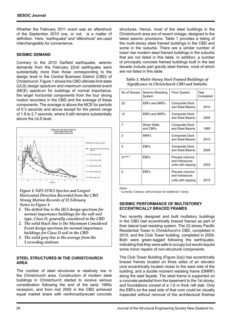
Contrary to the 2010 Darfield earthquake, seismic demands from the February 22nd earthquake were substantially more than those corresponding to the design level in the Central Business District (CBD) of Christchurch. Figure 1 shows the CBD ultimate limit state (ULS) design spectrum and maximum considered event (MCE) spectrum for buildings of normal importance, the larger horizontal components from the four strong motion recorders in the CBD and the average of these components. The average is above the MCE for periods of 0.3 seconds and above except for the period range of 1.8 to 2.7 seconds, where it still remains substantially above the ULS level.
Figure 1: NZS 1170.5 Spectra and Largest Horizontal Direction Recorded from the CBD Strong Motion Records of 22 FebruaryNotes to Figure 1:
1. The dotted line is the ULS design spectrum for normal importance buildings for the soft soil type, Class D, generally considered in the CBD
2. The solid black line is the Maximum Considered Event design spectrum for normal importance buildings for Class D soil in the CBD
3. The solid grey line is the average from the 5 recording stations
STEEL STRUCTURES IN THE CHRISTCHURCH aREa
The number of steel structures is relatively low in the Christchurch area. Construction of modern steel buildings in Christchurch started to receive serious consideration following the end of the early 1990s recession, and from mid 2000 in the CBD achieved equal market share with reinforced/precast concrete
structures. Hence, most of the steel buildings in the Christchurch area are of recent vintage, designed to the latest seismic provisions. Table 1 provides a listing of the multi-storey steel framed buildings in the CBD and some in the suburbs. There are a similar number of lower rise modern steel framed buildings in the suburbs that are not listed in this table. In addition, a number of principally concrete framed buildings built in the last decade include part gravity steel frames, most of which are not listed in this table.
Table 1. Multi-Storey Steel Framed Buildings of Significance in Christchurch CBD and Suburbs
No of Storeys Seismic-Resisting Floor System Year System Completed
22 EBFs and MRFs Composite Deck and Steel Beams 2010
12 EBFs and MRFs Composite Deck and Steel Beams 2009
7 Shear Walls Composite Deck and CBFs and Steel Beams 1985
3 MRFs Composite Deck and Steel Beams 2010
5 EBFs Composite Deck and Steel Beams 2008
3+Note 1 EBFs Precast columns and hollowcore units with topping 2003
5 EBFs Precast columns and hollowcore
units with topping 2010
Notes:1 Currently 3 storeys; with provision for additional 1 storey
SEISMIC PERFORMANCE OF MULTISTOREy ECCENTRICALLy BRACED FRAMES
Two recently designed and built multistory buildings in the CBD had eccentrically braced frames as part of their lateral load resisting system. The 22-storey Pacific Residential Tower in Christchurch’s CBD, completed in 2010, and the Club Tower building, completed in 2009. Both were green-tagged following the earthquake, indicating that they were safe to occupy but would require some minor repairs of non-structural components.
The Club Tower Building (Figure 2(a)) has eccentrically braced frames located on three sides of an elevator core eccentrically located closer to the west side of the building, and a ductile moment resisting frame (DMRF) along the east façade. The steel frame is supported on a concrete pedestal from the basement to the 1st storey, and foundations consist of a 1.6 m thick raft slab. Only the EBFs on the east side of that core could be visually inspected without removal of the architectural finishes

SESOC Journal
Volume 24 No. 2 September 2011 29
(Figure 2(d)). As observed following the September 2010 (Bruneau et al. 2010), evidence of inelastic deformation was limited to flaking of the brittle intumescent paint on the EBF links at some levels (Figure 2c). However later investigations have shown slightly more yielding in the active links of EBFs in the East-West direction. The links were free of visible residual distortions. Previously reported slab cracking (Bruneau et al. 2010) could not be detected as the concrete floor slab was covered by floor carpeting, except at one location at the fixed end of a segment of the floor cantilevering on one side of the building (a feature present only over two stories for architectural effect). Crack widths appeared similar to what had been previously observed. Substantial shear cracking of the gypsum plaster board (sheetrock) finish on the exterior wall of that cantilevering part of the floor was also observed (Figure 2(b)); only hairline cracking of gypsum plaster board finishes was observed elsewhere throughout the building. One non-structural masonry block installed for sound proofing purposes adjacent to mechanical units on the pedestal roof suffered minor shear cracking where it had been placed hard against a cantilevering floor beam.
Given the magnitude of the earthquake excitations, with demands above the ULS design level, substantial yielding of the EBF links would have been expected. EBFs designed in compliance with the NZS 3404 (SNZ, 1997/2001/2007) provisions are typically sized considering a ductility factor (µ, equivalent to Rµ in US practice) of up to 4, a level of link deformations that would correspond to significant shear distortions of the links. Yet, only minimal flaking of the paint in the EBF links was observed. A number of additional factors can explain behavior in this particular case, including strength of the composite floor slab action (neglected in design) and mobilization of the solid non-structural wall concrete cladding adjacent to the staircase.
The ductile MRF along the east wall did not show any evidence of yielding. Its design had been governed by the need to limit drift, particularly under torsional response due to the eccentricity of the core, and its corresponding effective ductility factor (µ) was low at 1.25.
Following repair of non structural wall cracking, the building was returned to full service in June 2011, being the first normal important multi-storey building in Christchurch to be back in operation. Realignment of the lift guide rails is ongoing to prevent increased wear of the lift system over time. Given that the building’s residual drift is 0.1% it appears that lift shafts are the most sensitive building service component to post-earthquake deformation and also that the 0.3% residual limit proposed by some for successful low damage building performance is too high.
Figure 2: Club Tower [Photos by M. Bruneau]
As a new landmark and the tallest building on the Christchurch skyline7, the 22-storey Pacific Residential Tower consists of perimeter EBFs up to the sixth floor (one on each building face), shifting to EBFs around the elevator core above that level, with a transfer slab designed to horizontally distribute the seismic loads at that transition point. EBFs at levels below the transfer slab were visible, as these levels housed a mechanical multilevel parking elevator system. The separate bracing system of that mechanical device consisted of flat plates connected with turnbuckles and hooks. Some of those details failed as the bars un-hooked when returning
a) Global view b) Cracking of partition in cantilevering portion of story
c) Paint flaking of partially hidden EBF link
d) Global view of EBF braces obstructed by various utility runs
7The Grand Chancellor Hotel is 85 metres, the Price Waterhouse Cooper building is 76.3 metres, and the C1 Building (a.k.a. the Pacific Tower) stands at 73 metres, is topped by a 13 metres spire, for a total of 86 metres.

SESOC Journal
30 Journal of the Structural Engineering Society New Zealand Inc.
into compression after tension yielding excursions that elongated the braces. The EBFs at intermediate locations were not integral with the floor slab and so did not benefit from the strength increase provided at lower stories. A range of views for this structure are given in Figure 3.
Paint flaking and residual link shear deformations were observed in the EBF links at those levels. Design of the EBFs in Pacific Residential Tower building was governed by the need to limit drift, with a corresponding resulting design ductility factor (µ) of 1.5 (even though up to 4.0 is permitted for EBF, as mentioned earlier). This is typical of EBFs in tall buildings in New Zealand’s moderate to low seismic zones; Christchurch is moderate in accordance with the earthquake loadings standard, NZS 1170.5, at the time of writing. The EBF at all other levels were hidden in architectural finishes, and absence of damage to those finishes suggested limited inelastic deformation, which has been confirmed by subsequent detailed evaluation. Initial concern that inelastic demand was higher in level 6 which is the level of a horizontal transfer diaphragm between the podium and tower was found not to be the case in this detailed evaluation.
Structurally and non-structurally this building could be rapidly put back into full service; however its location in the middle of the CBD red zone means there will be no public access to it in the near future.
(a) Global view
(b) and (c) Multistorey mechanical garage failed braces
(d) Flaked paint on EBF link
(e) Residual shear deformations of EBF link
Figure 3. Pacific Tower [Photos by M. Bruneau]

SESOC Journal
Volume 24 No. 2 September 2011 31
SEISMIC PERFORMANCE OF ECCENTRICALLy BRACED FRAMES IN PARkING GARAGES
The two low-rise parking garages having eccentrically braced frames described in Bruneau et al. (2010) were again inspected following the aftershock.
The EBFs in a three level parking garage of a shopping mall west of the CBD did not exhibit inelastic deformations (Figure 4(a)). However, there was some evidence of minor movement of the bolted splice connections in the braces. The basically elastic response of the EBFs is not surprising in this case, given that these frames had been designed to accommodate three additional parking levels to be added at a later time and the intensity of shaking was lower than in the CBD. Live load present at the time of the earthquake may also have been less than considered in design, although it was higher than in the September earthquake when the shopping mall was not occupied. Movement of precast units previously reported was observed to have intensified in the February earthquake but stable since. This resulted in fracture of the spandrel panels beside the epoxy mastic connection between panels presumably indicating that the epoxy mastic was stronger than the precast panels in tension (Figure 4(b)). These fractures occurred in all panels over the height of the structure. These spandrel panels were also designed to carry gravity loads in the parking structure so their fracture compromised the serviceability of the building.
(a) View from the east
(b) Fracture of precast spandrel beams on south side
Figure 4: Shopping mall on Dilworth St and
Clarence St, Christchurch [Photos by G. MacRae]
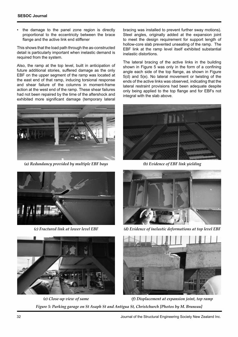
The EBFs in a hospital parking garage closer to the epicenter (Bruneau et al. 2010) also performed well, although some link fractures were observed in two braced bays (Figure 5). Note that at least six EBF frames were used at each level in each of the buildings’ principal directions, and that this significant redundancy contributed to maintain satisfactory seismic performance of the building in spite of those significant failures. Residual drifts of the parking structure were not visually noticeable, which suggests that these fractures would not have been discovered if hidden by non-structural finishes.
As previously mentioned this parking structure was also designed to accommodate three additional floors. Yet, some of the links at the first storey showed paint flaking as evidence of inelastic deformations. Evidence of soil liquefaction was also observed over parts of the slab on grade. Depending on the foundation type, liquefied soils can act as a sort of base isolation or as a method to lengthen the period. This generally results in a lower yield acceleration and lower structural demands. As such, it is possible that this parking garage was not subjected to ground motions as severe as those shown in Figure 1, in spite of being only 1.5 kms from Christchurch city centre. However, because these EBFs were not drift dominated they were designed for the maximum µ = 4 ductility demand. Also, these active links were added as finished components into the largely precast concrete structure and so were not tied into the floor slab with shear studs as they were for the taller buildings previously discussed. This meant that they did not have the same strength enhancement due to resistance to out of plane deformation of the floor slab as the taller buildings.
The fractures, as shown in closeup in Figure 5(c) were of particular concern as these were the first fractures recorded in EBFs worldwide. Further puzzlement was added by the fact that the fracture plane, shown in Figure 5(c), indicated a ductile overload failure rather than a brittle fracture. However, the likely explanation lies in the offset of the brace flange from the stiffener. This offset is shown in Figure 5(d) and means that, when the brace was loaded in tension, the axial tension force in the brace fed into the active link/collector beam panel zone through a flexible beam flange rather than directly into the stiffener. Thus the junction between the unstiffened beam flange and the beam web was overloaded, leading to fracture between these two surfaces and this fracture spreading across the beam flange and through the web. This is supported by the following facts:
• where the flanges of the brace line up with the stiffeners, as in the right hand side of the active link shown in Figure 5(b) or the panel zone shown in Figure 5(e), there was no damage to this panel zone region
SESOC Journal
32 Journal of the Structural Engineering Society New Zealand Inc.
• the damage to the panel zone region is directly proportional to the eccentricity between the brace flange and the active link end stiffener
This shows that the load path through the as-constructed detail is particularly important when inelastic demand is required from the system.
Also, the ramp at the top level, built in anticipation of future additional stories, suffered damage as the only EBF on the upper segment of the ramp was located at the east end of that ramp, inducing torsional response and shear failure of the columns in moment-frame action at the west end of the ramp. These shear failures had not been repaired by the time of the aftershock and exhibited more significant damage (temporary lateral
bracing was installed to prevent further sway motions). Steel angles, originally added at the expansion joint to meet the design requirement for support length of hollow-core slab prevented unseating of the ramp. The EBF link at the ramp level itself exhibited substantial inelastic distortions.
The lateral bracing of the active links in the building shown in Figure 5 was only in the form of a confining angle each side of the top flange, as shown in Figure 5(d) and 5(e). No lateral movement or twisting of the ends of the active links was observed, indicating that the lateral restraint provisions had been adequate despite only being applied to the top flange and for EBFs not integral with the slab above.
(a) Redundancy provided by multiple EBF bays (b) Evidence of EBF link yielding
(c) Fractured link at lower level EBF (d) Evidence of inelastic deformations at top level EBF
(e) Close-up view of same (f) Displacement at expansion joint, top ramp
Figure 5: Parking garage on St Asaph St and Antigua St, Christchurch [Photos by M. Bruneau]

SESOC Journal
Volume 24 No. 2 September 2011 33
CONNECTIONS
Connections in modern steel frames performed very well and as expected. Figure 6(a) shows a brace/beam/column connection in which the gusset plate is welded to the beam and bolted to the column with a flexible end-plate connection. This was designed and detailed to be rigid for vertical load transfer and flexible in the horizontal direction, to accommodate change in the angle between beam and column during the earthquake. This flexible endplate has undergone limited out-of-plane yielding, protecting the gusset plate from inelastic demand. Figure 6(b) shows a flush endplate splice in a MRF beam that has performed well.
In a moment endplate connection in a portal frame building in a strongly shaken region on soft ground near the fault, one example of a row of bolts in a moment endplate (MEP) connection in a portal frame suffering tension failure has been observed. The connection had not opened up during the earthquake and was rapidly repaired.
(a) Brace/beam/column connection showing out-of-plane yielding in endplate but no
inelastic demand in gusset plate
(b) Flush moment endplate splice connection
Figure 6: Connections in Club Tower Building, Christchurch [Photos by G C Clifton]
CONCENTRICALLy BRACED FRAMED BUILDINGS
A single suspended level parking garage with concentrically braced frame (CBF) was found to have performed poorly (Figure 7). The garage had solid pre-cast panel walls on three sides, and two individual CBF bays along the fourth side (one bay on each side of the garage door). While the columns of the westernmost CBF tied to a steel beam at their top, the easternmost CBF was not similarly aligned with a steel beam. A non-ductile reinforced concrete extension framing into a concrete beam at the top performed poorly. The other brace of that frame failed at the welds under tension loads; these welds did not appear to be designed to develop the tension capacity of the brace according to the capacity design principles of NZS 3404. The westernmost CBF performed better, without fractures, with visible post-earthquake residual buckling as a consequence of brace elongation.
(a) Poor column connection detail
(b) Buckled brace
Figure 7: Low-rise CBF parking garage [Photos by M. Bruneau] (continued)

SESOC Journal
34 Journal of the Structural Engineering Society New Zealand Inc.
(c) and (d) Fractured non-ductile brace-to-column connection
Figure 7: Low-rise CBF parking garage [Photos by M. Bruneau] (concluded)
A seven storey steel framed hotel building with combination shear walls in one direction and CBFs in the other direction, could not be inspected because of its immediate proximity to the 22 storey Grand Chancellor Hotel which was considered to be in a state of imminent collapse due to fatal damage in lower level shear walls of its concrete frame system. It is hoped to visit this building, if it is still intact, once the Grand Chancellor has been demolished.
MULTI-STOREy MOMENT RESISTING FRAMED BUILDINGS
A new parking garage (construction completed after the September 2010 earthquake) appeared to have performed very well, with no visible sign of inelastic deformation at the beam-to-column connections (Figure 8) or in any other part of the structure. However, this assessment could only be done from a distance as a pre-existing post-tensioned concrete section of that garage (together with the spans between the older and newer part of that parking garage) collapsed onto its access ramp.
A low-rise MRF building housing a gymnasium in the same vicinity suffered no structural damage but some movement due to ground instability and cracking in the ground floor slab on grade. Some heavy ceiling mounted equipment had detached during the February earthquake.
(a) Global view
(b) Typical moment connections
Figure 8: Low-rise MRF parking garage [Photos by M. Bruneau]

SESOC Journal
Volume 24 No. 2 September 2011 35
HISTORICAL BUILDINGS
Partial out-of-plane failure around the dome at the top of the Regent Theatre) Building revealed that a braced steel frame had been used there (Figure 9). Although subsequent inspection will be required to verify the integrity of the connections, it appeared to be in good condition from a distance. The building was built before 1910 and the scene was reminiscent of pictures of similar buildings following the 1906 San Francisco earthquake. However, the CBFs appeared to be welded construction (to be verified) which means they are likely to be newer than the rest of the building and had been added in a subsequent retrofit.
(a) Global view
(b) Close-up view
Figure 9: Braced dome at top of Regent on Worchester Building [Photos by M. Bruneau]
Steel braced frames were sometimes used to retrofit unreinforced masonry structures (e.g. Figure 10). Drift limits to prevent failure of the unreinforced masonry typically govern design in those instances, which explain the significant member sizes of these frames proportional to the reactive mass, and their elastic response.
(a) Close-up view
(b) Global view
Figure 10: Braced frame as a retrofit to unreinforced masonry building [Photos by M. Bruneau]

SESOC Journal
36 Journal of the Structural Engineering Society New Zealand Inc.
Buildings in the CBD that had been strengthened prior to the September 2010 earthquake typically suffered minimal to no damage in that event. They were not so fortunate in the much stronger February 2011 event. In part this is likely because the acceptable strengthening requirements were less than full design levels demanded of modern buildings. Figure 11 shows one group of three buildings, with (a) showing these following the September 2010 event and (b) showing (from a different vantage point) the three following the February 2011 event. Note especially the strengthened building on the corner has collapsed.
(a) is following the September 2010 event
(b) Following the February 2011 event, taken from a slightly different view-point
Figure 11: Strengthened URM buildings
INDUSTRIAL AND EDUCATIONAL FACILITIES
Many warehouses close to the epicenter suffered limited damage. These industrial facilities typically have light roofs and are designed to resist high wind forces; light rod braces are typically used for this purpose. Following the earthquakes, steel fabricators inspected multiple warehouses, and retightened sagging braces that had stretched due to yielding during the earthquake.
As was the case following the September 2010 Darfield earthquake, a proprietary system often used in these warehouses (sold as a kit) which used a particular banana end fitting, suffered some brittle failures of the cast-steel connectors (as shown in Figure 12). These occurred in a new warehouse when the fitting fell to the ground following the shearing of the pin retaining clip. Some engineers have expressed concerns regarding their potential brittleness and believe that their performance needs to be validated under a dynamic test regime.
(a) Global view
(b) Close-up viewFigure 12: Example of fractured banana end of
proprietary brace connector in the roof plane of a long span steel portal frame building
[Photos by M. Bruneau]

SESOC Journal
Volume 24 No. 2 September 2011 37
Extensive failure of steel storage racks was observed in industrial facilities, in some cases in spite of additional measures taken following the September earthquake. For example, one facility owner who had racks stacked 6 pallet-levels high that collapsed during the September 2010 earthquake, purchased new racks “designed to resist Magnitude 7 earthquakes of the type expected in [the most active seismic zone of] Wellington” and re-structured his operations to limit stacking to three levels. In spite of those measures, all racks experienced
total collapse, as shown in Figure 13. It appeared that the semi-rigid beam to column connections in the longitudinal direction were too weak for the intensity of shaking and imposed gravity loads. In the transverse direction there were examples of brace system failure due to baseplate tearout from the floor when the column went into tension, which forced the seismic base shear into the compression column leading to rapid failure of this column.
Figure 13: Example of collapsed industrial storage racks [Photos by M. Bruneau and G C Clifton]

SESOC Journal
38 Journal of the Structural Engineering Society New Zealand Inc.
Anecdotally, in another facility, existing racks had been retrofitted by coupling two racks back-to-back with flat bar braces (Figure 14). These bars showed evidence of elongation and residual buckling, but did not collapse, in spite of floor movements due to liquefaction, whereas the only rack that was not retrofitted (for it was not adjacent to a second rack to which it could have been tied) collapsed.
These above selected examples highlight the fact that performance of industrial storage racks is a major issue that remains to be satisfactorily addressed; although the performance has to be considered in light of the very high intensity of shaking.
(a) Global view
(b) Close–up of buckled brace
Figure 14: Industrial storage racks that survived, with evidence of soil liquefaction [Photos by M. Bruneau]
Multiple examples of tilt-up panel movements due to ground liquefaction were observed, sometimes leading to fracture of non-ductile braces unable to accommodate the imposed deformations. One such example is seen in Figure 15, showing a fractured brace and its counterpart buckled brace.
(a) Global view, showing buckled brace and fractured brace
(b) Close–up view of fractures weld of tension brace
Figure 15: Industrial facility roof bracing [Photos by M. Bruneau]
Anchorage of tilt-up walls to steel structures also failed in a few instances. Figure 16 shows roof beams buckled in compression by the inward movement of the tilt-up panels, and failure of the anchors due to their outward movement (i.e. away from the building). Given that this happened in modern construction, and because tilt-up walls of greater slenderness have progressively been implemented in New Zealand, a careful re-assessment of their seismic design provisions may be desirable.

SESOC Journal
Volume 24 No. 2 September 2011 39
Figure 17 shows the steel structure standing when the roofing has collapsed. This shows remarkable performance of the steel members, but poor performance of the roofing/connections.
Figure 17 : Failure of roof and walls in older industrial facility on Salisbury Street [Photos by G. MacRae]
(a) Global view (b) Close–up view of fractures connection
(c) Global view of buckled beams (d) Local view of one such beam
Figure 16 : Failure of tilt-up panel connections [Photos by M. Bruneau]

SESOC Journal
40 Journal of the Structural Engineering Society New Zealand Inc.
At Heathcote Valley Primary School some of the most extreme shaking during the event was recorded. There was one new single storey building with a steel moment frame and block walls as shown in Figure 18(a). After the earthquake the wall was leaning to the east at the southern end, and to the west at the northern end. The concrete baseplate was blown out on the southeast side of the building as shown in Figure 18(b).
(a) Overall view from the south
(b) Baseplate bolt at SE corner of the building
Figure 18. Heathcote Valley Primary School steel moment frame building (Photos: MacRae)
A steel framed wall with a brick façade was erected in a small park as shown in Figure 19, in a part of town where significant overall structural damage occurred. The wall was placed there after the September 2010 earthquake as states “Rebuild, Brick by Brick”. The bricks were fixed to the steel frame with conventional brick ties as used in framing construction. The wall suffered no damage in the subsequent 5 earthquakes of the series.
(a) Overall view of wall
(b) Back view of wall
Figure 19. September 2010 rebuilding stand consisting of bricks supported by
steel frame (Photos: MacRae)

SESOC Journal
Volume 24 No. 2 September 2011 41
LIGHT STEEL FRAMED HOUSES
There are a small number of light steel framed houses in the affected area. Preliminary reports are that damage to framing, brickwork and linings was less in the 5 subsequent earthquakes than from the September earthquake, discounting damage resulting from soil liquefaction and lateral spreading.
BRIDGES
There are relatively few steel bridges in the Christchurch area. A pedestrian arch bridge at the Antigua Boatsheds and one at Victoria Square showed no visible damage (Figure 20).
Figure 20 – Undamaged older steel pedestrian bridges on the Avon Rover near the CBD (Leon)
Although substantial liquefaction occurred along the Avon River near the CBD, the only older steel bridge in this area did show spectacular buckling of its fascia arches; the actual bridge, supported on straight riveted girders appeared undamaged even though large settlements had occurred at the abutments (Figure 21). The old rail bridge over the Waimakariri river behaved well even though it was clear that the pier had moved over 100 mm toward the river and back during this shake (Figure 22(a)). The old road bridge suffered some longitudinal buckling of the lower flange of one beam (Figure 22(b)) as well as some spalling of concrete on the west side of the abutment. The only major modern steel bridge at the Port of Lyttleton, a three-span continuous plate girder, had only minor damage at the abutment (Figure 23).
(a) Slumping of riverbank close to bridge
(b) Buckling of fascia arches
(c) Slumping of abutments at end of bridge
(d) Undamaged straight riveted girders
Figure 21 – Colombo Street bridge (Leon)

SESOC Journal
42 Journal of the Structural Engineering Society New Zealand Inc.
(a) Old rail bridge
(b) Old road bridgeFigure 22 – Waimakariri Bridges, South end, (MacRae)
(a) Plate girder
(b) Abutment spallingFigure 23 – Lyttleton Port Bridge (MacRae)
CONCLUSIONS
Steel structures generally performed very well during the Christchurch earthquake series of 2010 and 2011. However, poor design and or detailing resulted in a few eccentrically braced frames, developing link fractures and CBF braced fractures. This shows the importance of good detailing, load path development and robust connections. Also multiple industrial steel storage racks collapsed, likely due to overloading.
This earthquake series comprised of 6 damaging events, the 4 most intense being at 1.8x, 0.9x, 0,7x and 0,6x design level intensity respectively. The cumulative duration of strong ground shaking was some 60 seconds. The number of inelastic excursions and pattern of response would have been different to that from one continuous event and the influence of this needs to be considered in ongoing research. The earthquake series has provided a wealth of data to allow more accurate validation of building models and numerical response procedures.
ACkNOWLEDGMENTS
This work was funded in part by the Foundation for Research in Science and Technology through the Engineering theme of the Natural Hazards Platform of New Zealand, the University of Auckland, the University of Canterbury, the Erskine Visiting Fellowship program at the University of Canterbury. Participation of Michel Bruneau to this earthquake reconnaissance study was funded by MCEER (University at Buffalo). Ron DeVall (Read Jones Christoffersen Ltd, Vancouver, Canada) is also thanked for sharing insights on the behavior of EBFs. However, any opinions, findings, conclusions, and recommendations presented in this paper are those of the writers and do not necessarily reflect the views of the sponsors.
REFERENCES
Bruneau, M., Anagnostopoulou, M., MacRae, G., Clifton, C., Fussell, A., “PRELIMINARY REPORT ON STEEL BUILDING DAMAGE FROM THE DARFIELD EARTHQUAKE OF SEPTEMBER 4, 2010”, Bulletin of the New Zealand Society for Earthquake Engineering, Vol.43, No.4, pp.351-359.
Hayes, G. et al, “THE 09/03/2010 DARFIELD EARTHQUAKE AND ITS AFTERSHOCKS, INCLUDING THE 02/21/2011 CHRISTCHURCH EVENT”, Educational Slides, US Geological Survey, National Earthquake Information Center, 2011.
Standards New Zealand, NZS 1170 Part 5: 2004 ‘Earthquake actions – New Zealand’ part of the Joint Australasian Loadings Standard set AS/NZS 1170 ‘Structural Design Actions’.
Standards New Zealand, NZS 3404: 1997 incorporating Amendment No. 1:2001 and Amendment No. 2: 2007, Standards New Zealand, Wellington, New Zealand.
GNS, CHRISTCHURCH CENTRAL BUSINESS DISTRICT SPECTRA, 25/02/2011.