Embed Size (px)
Citation preview
59
The RIBA Journal January 2015
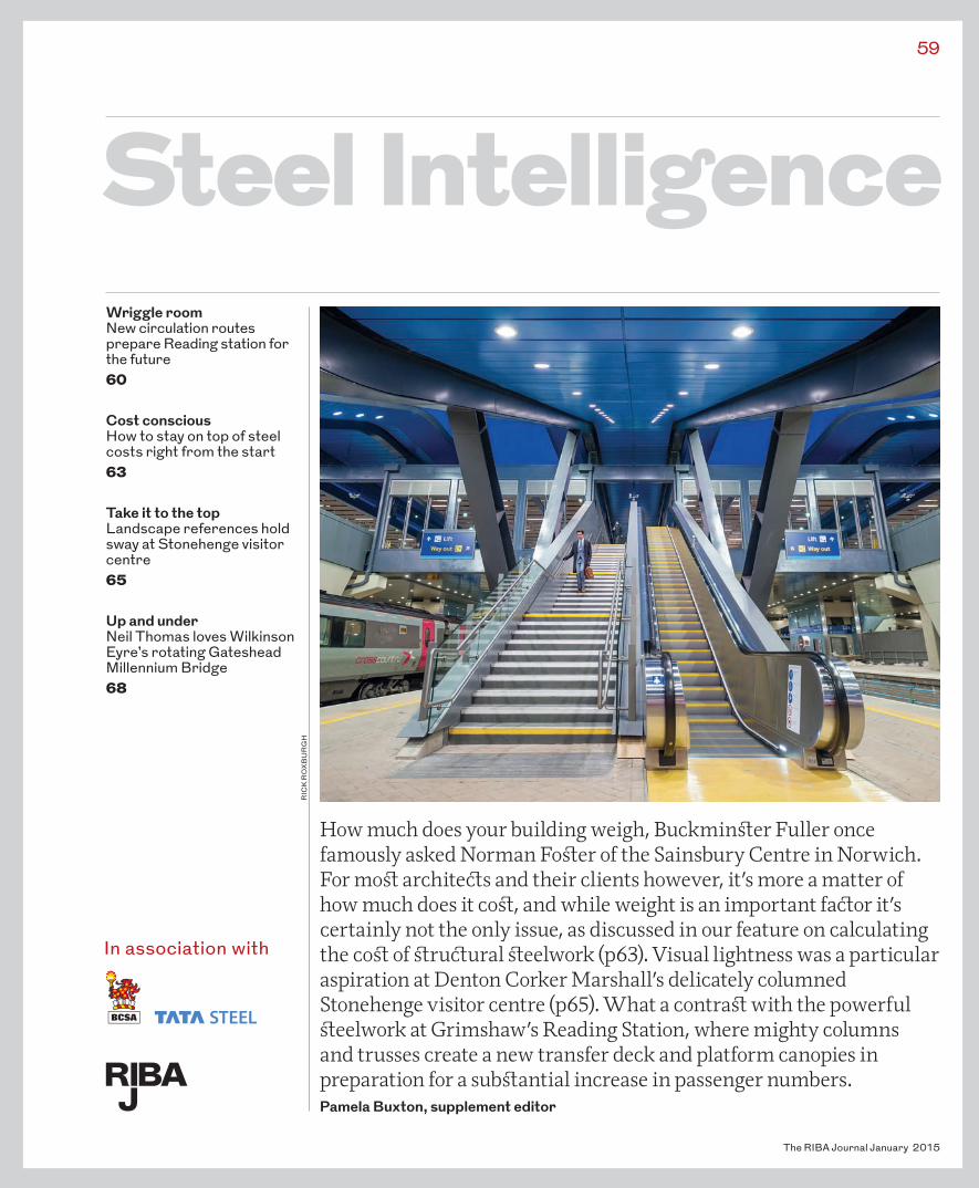
How much does your building weigh, Buckmin er Fuller once famously asked Norman Fo er of the Sainsbury Centre in Norwich. For mo archite� s and their clients however, it’s more a matter of how much does it co , and while weight is an important fa� or it’s certainly not the only issue, as discussed in our feature on calculating the co of ru� ural eelwork (p63). Visual lightness was a particular aspiration at Denton Corker Marshall’s delicately columned Stonehenge visitor centre (p65). What a contra with the powerful eelwork at Grimshaw’s Reading Station, where mighty columns and trusses create a new transfer deck and platform canopies in preparation for a sub antial increase in passenger numbers.Pamela Buxton, supplement editor
RIC
K R
OX
BU
RG
H
Steel IntelligenceWriggle roomNew circulation routes prepare Reading station for the future60
Cost consciousHow to stay on top of steel costs right from the start63
Take it to the topLandscape references hold sway at Stonehenge visitor centre65
Up and underNeil Thomas loves Wilkinson Eyre’s rotating Gateshead Millennium Bridge68
In association with
59_BCSA_COVER_2.indd 59 18/12/2014 13:20
The RIBA Journal January 2015
60 Steel IntelligenceReading station
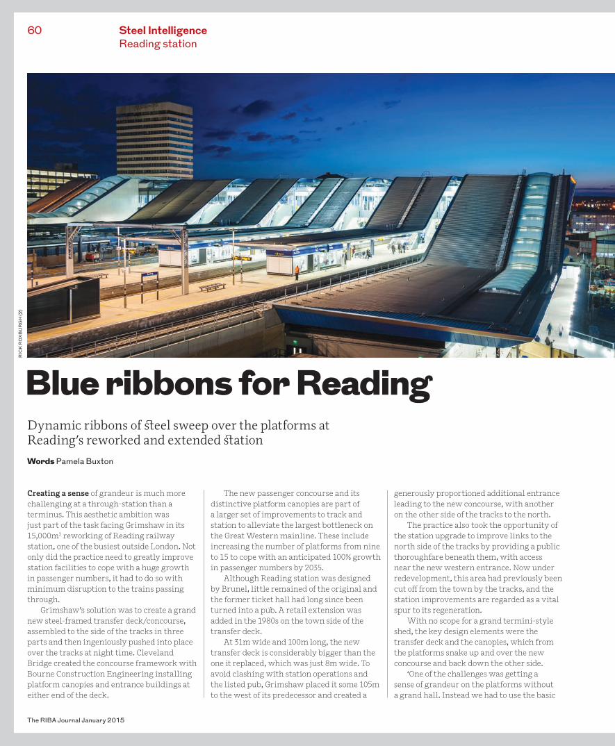
Creating a sense of grandeur is much more challenging at a through-station than a terminus. This aesthetic ambition was just part of the task facing Grimshaw in its 15,000m2 reworking of Reading railway station, one of the busiest outside London. Not only did the practice need to greatly improve station facilities to cope with a huge growth in passenger numbers, it had to do so with minimum disruption to the trains passing through.
Grimshaw’s solution was to create a grand new steel-framed transfer deck/concourse, assembled to the side of the tracks in three parts and then ingeniously pushed into place over the tracks at night time. Cleveland Bridge created the concourse framework with Bourne Construction Engineering installing platform canopies and entrance buildings at either end of the deck.
The new passenger concourse and its distinctive platform canopies are part of a larger set of improvements to track and station to alleviate the largest bottleneck on the Great Western mainline. These include increasing the number of platforms from nine to 15 to cope with an anticipated 100% growth in passenger numbers by 2035.
Although Reading station was designed by Brunel, little remained of the original and the former ticket hall had long since been turned into a pub. A retail extension was added in the 1980s on the town side of the transfer deck.
At 31m wide and 100m long, the new transfer deck is considerably bigger than the one it replaced, which was just 8m wide. To avoid clashing with station operations and the listed pub, Grimshaw placed it some 105m to the west of its predecessor and created a
generously proportioned additional entrance leading to the new concourse, with another on the other side of the tracks to the north.
The practice also took the opportunity of the station upgrade to improve links to the north side of the tracks by providing a public thoroughfare beneath them, with access near the new western entrance. Now under redevelopment, this area had previously been cut o� from the town by the tracks, and the station improvements are regarded as a vital spur to its regeneration.
With no scope for a grand termini-style shed, the key design elements were the transfer deck and the canopies, which from the platforms snake up and over the new concourse and back down the other side.
‘One of the challenges was getting a sense of grandeur on the platforms without a grand hall. Instead we had to use the basic
Blue ribbons for Reading Dynamic ribbons of �eel sweep over the platforms at Reading’s reworked and extended �ation Words Pamela Buxton
RIC
K R
OX
BU
RG
H (2
)
60_READING-STATION.indd 60 10/12/2014 15:17
61
The RIBA Journal January 2015
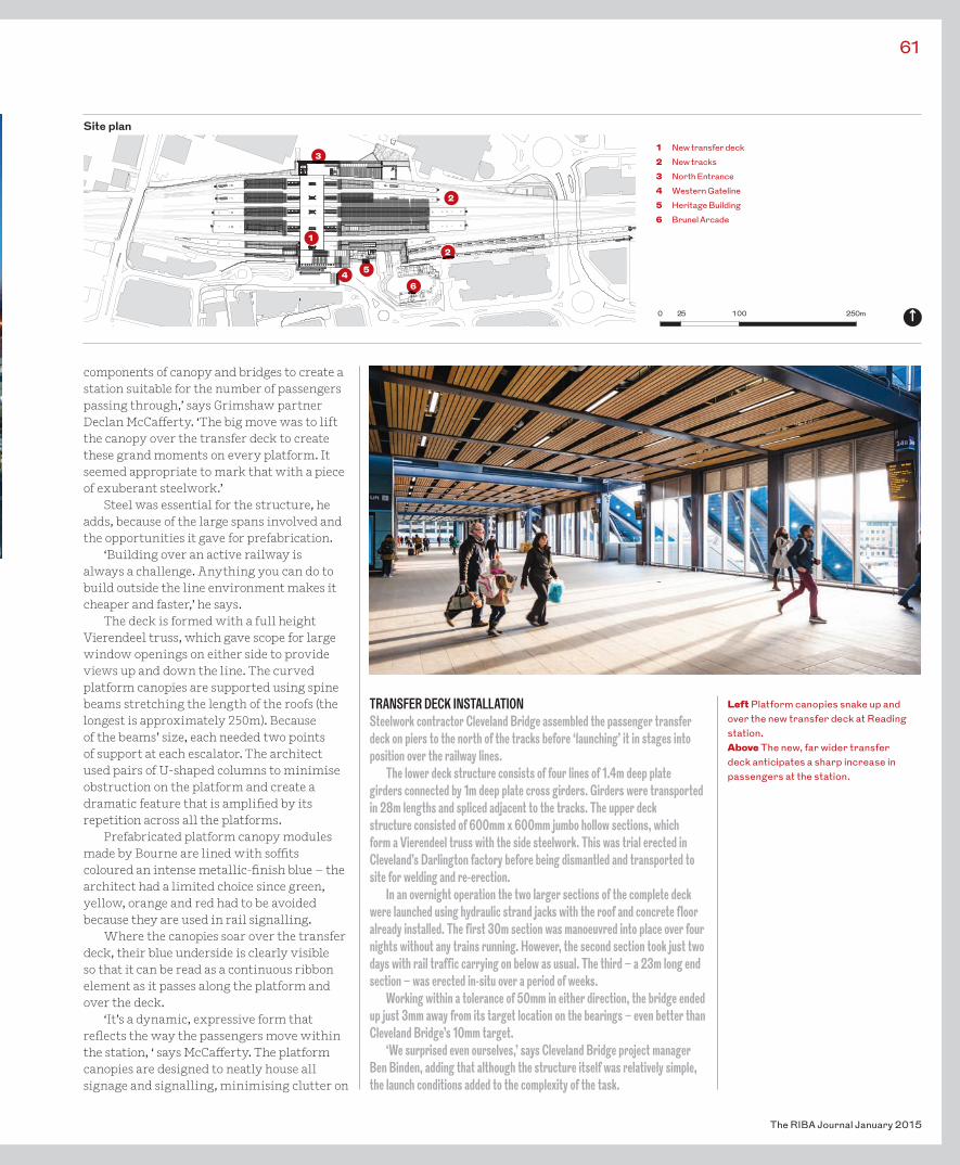
components of canopy and bridges to create a station suitable for the number of passengers passing through,’ says Grimshaw partner Declan McCa� erty. ‘The big move was to lift the canopy over the transfer deck to create these grand moments on every platform. It seemed appropriate to mark that with a piece of exuberant steelwork.’
Steel was essential for the structure, he adds, because of the large spans involved and the opportunities it gave for prefabrication.
‘Building over an active railway is always a challenge. Anything you can do to build outside the line environment makes it cheaper and faster,’ he says.
The deck is formed with a full height Vierendeel truss, which gave scope for large window openings on either side to provide views up and down the line. The curved platform canopies are supported using spine beams stretching the length of the roofs (the longest is approximately 250m). Because of the beams’ size, each needed two points of support at each escalator. The architect used pairs of U-shaped columns to minimise obstruction on the platform and create a dramatic feature that is ampli� ed by its repetition across all the platforms.
Prefabricated platform canopy modules made by Bourne are lined with so� ts coloured an intense metallic-� nish blue – the architect had a limited choice since green, yellow, orange and red had to be avoided because they are used in rail signalling.
Where the canopies soar over the transfer deck, their blue underside is clearly visible so that it can be read as a continuous ribbon element as it passes along the platform and over the deck.
‘It’s a dynamic, expressive form that re� ects the way the passengers move within the station, ‘ says McCa� erty. The platform canopies are designed to neatly house all signage and signalling, minimising clutter on
Left Platform canopies snake up and over the new transfer deck at Reading station.Above The new, far wider transfer deck anticipates a sharp increase in passengers at the station.
TRANSFER DECK INSTALLATIONSteelwork contractor Cleveland Bridge assembled the passenger transfer deck on piers to the north of the tracks before ‘launching’ it in stages into position over the railway lines.
The lower deck structure consists of four lines of 1.4m deep plate girders connected by 1m deep plate cross girders. Girders were transported in 28m lengths and spliced adjacent to the tracks. The upper deck structure consisted of 600mm x 600mm jumbo hollow sections, which form a Vierendeel truss with the side steelwork. This was trial erected in Cleveland’s Darlington factory before being dismantled and transported to site for welding and re-erection.
In an overnight operation the two larger sections of the complete deck were launched using hydraulic strand jacks with the roof and concrete floor already installed. The first 30m section was manoeuvred into place over four nights without any trains running. However, the second section took just two days with rail traffic carrying on below as usual. The third – a 23m long end section – was erected in-situ over a period of weeks.
Working within a tolerance of 50mm in either direction, the bridge ended up just 3mm away from its target location on the bearings – even better than Cleveland Bridge’s 10mm target.
‘We surprised even ourselves,’ says Cleveland Bridge project manager Ben Binden, adding that although the structure itself was relatively simple, the launch conditions added to the complexity of the task.
Site plan
1
2
2
31 New transfer deck2 New tracks 3 North Entrance4 Western Gateline5 Heritage Building6 Brunel Arcade
4 5
6
0 25 100 250m
60_READING-STATION.indd 61 10/12/2014 15:20
the platforms. A smooth so�t was essential to avoid opportunities for pigeons to roost.
A particularly challenging part of the station steelwork was the six curved jumbo sections in the new Western Gateline building. These were bent in the UK by Angle Ring Company to give the appearance of a continuous beam with three bends at the top and three at the bottom.
The transfer deck completed in the summer, a year ahead of schedule. According to engineer Tata Steel Projects, it is the largest pedestrian structure in the UK rail system. During the course of the project, it was announced that Crossrail would be extended to Reading by 2019, making the new concourse’s extra capacity all the more essential. •
The RIBA Journal January 2015
62 Steel IntelligenceReading station
ST
EV
E K
EN
NE
DY
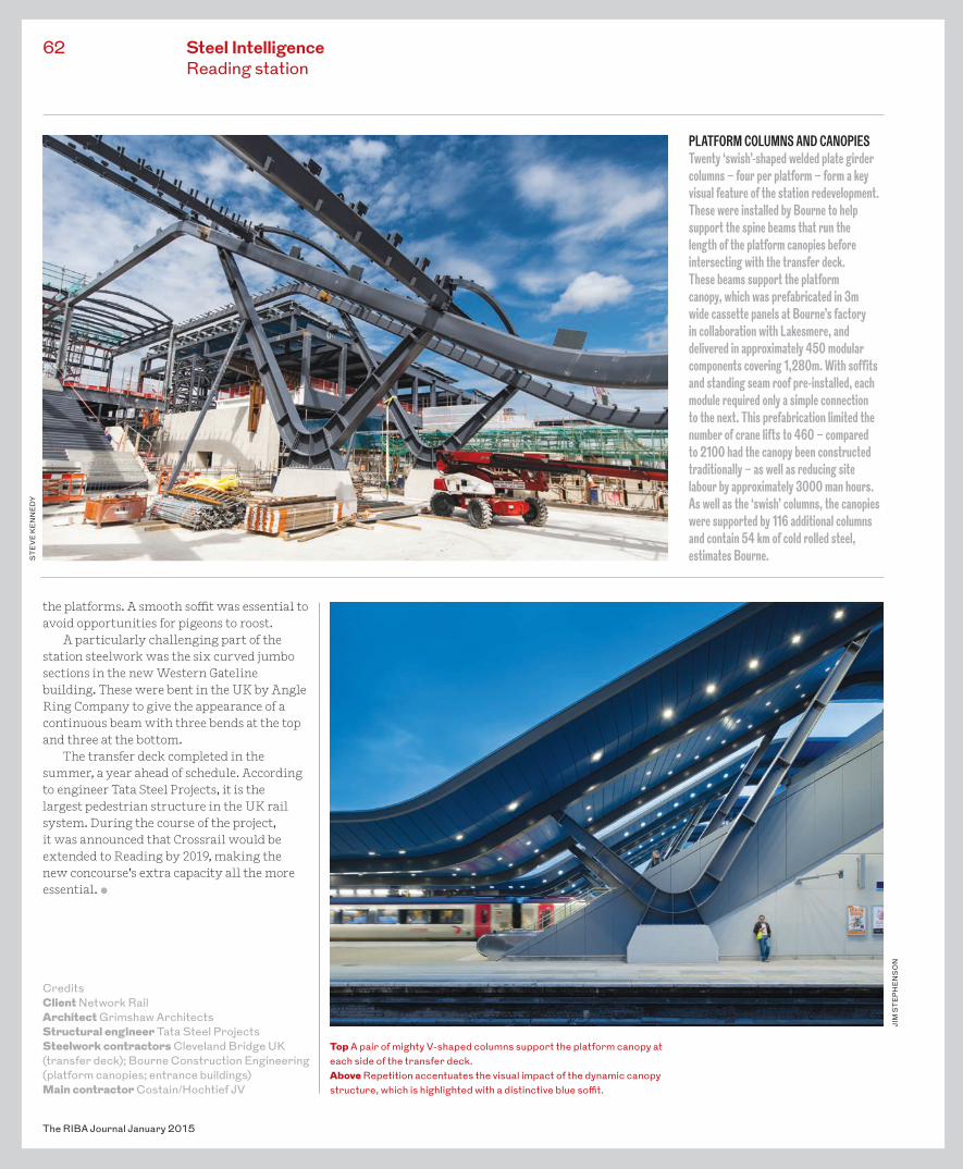
PLATFORM COLUMNS AND CANOPIES Twenty ‘swish’-shaped welded plate girder columns – four per platform – form a key visual feature of the station redevelopment. These were installed by Bourne to help support the spine beams that run the length of the platform canopies before intersecting with the transfer deck. These beams support the platform canopy, which was prefabricated in 3m wide cassette panels at Bourne’s factory in collaboration with Lakesmere, and delivered in approximately 450 modular components covering 1,280m. With soffits and standing seam roof pre-installed, each module required only a simple connection to the next. This prefabrication limited the number of crane lifts to 460 – compared to 2100 had the canopy been constructed traditionally – as well as reducing site labour by approximately 3000 man hours. As well as the ‘swish’ columns, the canopies were supported by 116 additional columns and contain 54 km of cold rolled steel, estimates Bourne.
CreditsClient Network RailArchitect Grimshaw ArchitectsStructural engineer Tata Steel ProjectsSteelwork contractors Cleveland Bridge UK (transfer deck); Bourne Construction Engineering (platform canopies; entrance buildings)Main contractor Costain/Hochtief JV
Top A pair of mighty V-shaped columns support the platform canopy at each side of the transfer deck.Above Repetition accentuates the visual impact of the dynamic canopy structure, which is highlighted with a distinctive blue so�t.
JIM
ST
EP
HE
NS
ON
60_READING-STATION.indd 62 10/12/2014 15:17
Steel IntelligenceCosting steel
While architects don’t need to know in detail how to cost buildings, if you want to avoid a nasty surprise when the tenders come back in, you do need a general understanding of the cost impact of the concept design decisions you make. This is especially true on smaller projects which may not have a cost consultant.
Frame choice has a huge impact on design decisions from foundations to cladding as well as the construction programme. Since it is rarely changed at a later stage, it’s important to have a clear idea of the cost implications when the initial frame decision is made.
At an early stage, cost consultants use cost models, historical data and benchmarking to arrive at a rate per m2 based on gross internal �oor area (GIFA) before re ning these to suit the particular project and market conditions. At a later stage, when the primary and secondary members have been nalised, the cost consultant will measure the length of each structural member and multiply it by the relevant weight in kg/m before applying a cost per tonne to each frame element.
Key determining factorsThe key steel cost drivers below remain the same whatever the trends in tender prices.Location This is a major cost variant. Indices such as those produced by the BCIS provide cost adjustment factors for location; for example Belfast is the cheapest place in the UK to build, while the City of London is by far the most costly. Logistics Site speci c conditions are also relevant when it comes to costs. Whereas there might be easy access when building an isolated business park, the restraints of a busy city centre site can have a major impact on the installation programme because of limitations imposed on deliveries, storage, noise, craneage and working hours. Less constrained sites might also allow more standard framing solutions while those requiring non-standard grids will reduce the level of repetition and so increase costs.Function, sector and building height Due to their di�erent usage and subsequent varying frame weight, sectors can show a
wide disparity in typical costs for the same �oorspace. Longer spans – particularly desirable in speculative commercial spaces – generally mean heavier sections and a heavier overall frame, although cellular beams can lead to subsequent savings by reducing the depth of the �oor and services zone. An industrial shed, for example, might have a frame weight of 40kg/m² GIFA compared with a long-span city o�ce building’s 90kg/m² GIFA. Overall building height is another
63
The RIBA Journal January 2015
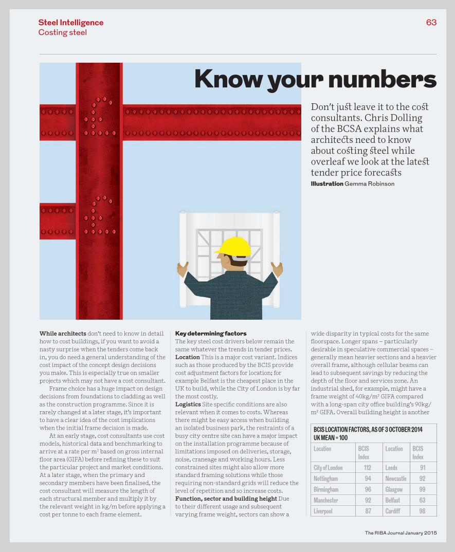
Know your numbers Don’t ju� leave it to the co� consultants. Chris Dolling of the BCSA explains what archite�s need to know about co�ing �eel while overleaf we look at the late� tender price foreca�sIllustration Gemma Robinson
BCIS LOCATION FACTORS, AS OF 3 OCTOBER 2014UK MEAN = 100
Location BCIS Index
Location BCIS Index
City of London 112 Leeds 91
Nottingham 94 Newcastle 92
Birmingham 96 Glasgow 99
Manchester 92 Belfast 63
Liverpool 87 Cardiff 98
63_BCSA_COSTING STEEL.indd 63 10/12/2014 15:21
important factor since a higher steel frame weight per kg/m² is required on multi-storey construction.
The table below gives indicative costs for three types of multi storey building and two types of industrial steel buildings.Building type Particular sectors have special cost factors to consider for steel. Both healthcare – in particular hospitals –and education buildings require a mix of facilities that will often use di� erent grids and loadings and will be outside standard cost ranges. In both these sectors, partnering and framework arrangements are common – which may mean that costs have already been set out for a number of projects and will have a bearing on initial estimates. Education buildings can also be subject to costs associated with a timetable driven by the academic year. Form and complexity Form is often more relevant than the quantity of steel involved since simple steelwork is far cheaper than complex designs. Complex forms generally increase the need for non-standard sections and connections, and may require more
complex structural solutions such as transfer structures and fabricated beams, which will also push costs higher. Varying the � oor-to-� oor heights can also have knock-on e� ect on other costs such as substructure and cladding.
Likewise, buildings with a high degree of standardisation are more likely to conform to traditional build costs.
Structural frame cost breakdown Minimum weight doesn’t necessarily mean minimum cost. Raw material proportionally accounts for just 30-40% of the total steel frame according to the BCSA, with fabrication accounting for a similar proportion followed by � re protection and erection at 10-15% each. Steel design and engineering accounts for 2% and transport for the remaining 1%.
Common pitfallsBeware simplistic comparisons with the costs of previous projects. It’s tempting to look at a super� cially similar project of twice the size and estimate that the steelwork for the new project would therefore cost roughly half as much. But that doesn’t take into account all sorts of factors such as the size of spans, � re protection, cladding, service integration, and overall construction programme. For specialist systems such as cellular beams, shallow � oors or steel bearing piles, the cost of the system itself should not be looked at in isolation but considered in tandem with the many implications of the choice. The most cost e� ective solutions are those that achieve the best balance between the product cost and the fabrication/erection time. •
The RIBA Journal January 2015
64
TENDER PRICES ON THE RISETender prices are generally on the up according to the latest market figures from Gardiner & Theobald (G&T). The firm forecasts a 4% rise in average tender rates across the UK in 2014 followed by 3.5% in 2015 and 2016 and 4% in 2017. In London, the increase is 6% for 2014 then 4.5%, 4% and 3.5% for the next three years.
Development activity has been particularly strong in the residential sector in London and the south east, but major regional cities have also shown growth. G&T senior associate Rachel Oldham expects demand for commercial space and infrastructure work to rise in the near future.
With five year cumulative rise forecasts of 22% for the UK, substantial inflation allowances should be built in when costing projects going out for tender in the future.
‘With the decision on which framing material and configuration to use taken quite early in the process, it can be difficult in changing market conditions to identify the most cost effective framing solution. So it’s important to keep talking to the supply chain to understand lead times and how the market is changing,’ says Oldham.
Structural steel and concrete both showed tender price rises for the second and third quarters of 2014 in response to increased demand in the commercial sector in particular, according to cost indices from the Department for Business, Innovation and Skills. Compared with the start of the year however, structural steel prices remain at a similar level while concrete and cement have risen by 3% and 5%. Manufacture of structural steel sections increased in price by £20/tonne in May 2014, and the BCSA expects structural steelwork prices to increase steadily in comparison to other construction materials.
G&T’s research is in the latest version of Steel Construction: Cost, published by BCSA and Tata Steel. This also includes an update of its ongoing study on comparative framing costs, which shows that steel remains a competitive framing material. Below are rates for Q3 2014 on GIFA basis for a City of London location.
Steel IntelligenceCosting steel
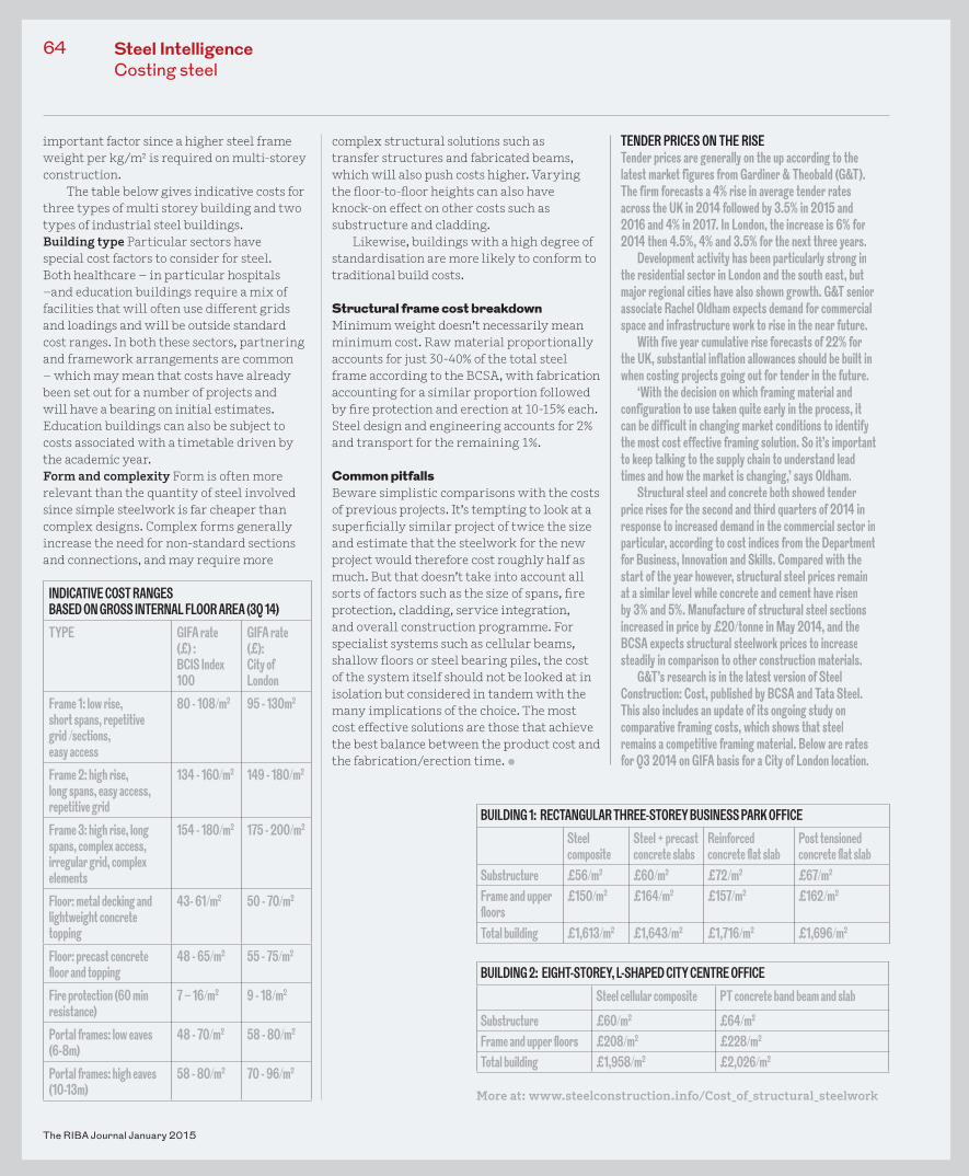
INDICATIVE COST RANGES BASED ON GROSS INTERNAL FLOOR AREA (3Q 14)
TYPE GIFA rate (£) :BCIS Index 100
GIFA rate (£): City of London
Frame 1: low rise,short spans, repetitivegrid /sections, easy access
80 - 108/m2 95 - 130m2
Frame 2: high rise, long spans, easy access, repetitive grid
134 - 160/m2 149 - 180/m2
Frame 3: high rise, long spans, complex access, irregular grid, complex elements
154 - 180/m2 175 - 200/m2
Floor: metal decking and lightweight concrete topping
43- 61/m2 50 - 70/m2
Floor: precast concrete fl oor and topping
48 - 65/m2 55 - 75/m2
Fire protection (60 min resistance)
7 – 16/m2 9 - 18/m2
Portal frames: low eaves (6-8m)
48 - 70/m2 58 - 80/m2
Portal frames: high eaves (10-13m)
58 - 80/m2 70 - 96/m2
BUILDING 1: RECTANGULAR THREE-STOREY BUSINESS PARK OFFICE
Steel composite
Steel + precast concrete slabs
Reinforced concrete fl at slab
Post tensioned concrete fl at slab
Substructure £56/m2 £60/m2 £72/m2 £67/m2 Frame and upper fl oors
£150/m2 £164/m2 £157/m2 £162/m2
Total building £1,613/m2 £1,643/m2 £1,716/m2 £1,696/m2
BUILDING 2: EIGHT-STOREY, L-SHAPED CITY CENTRE OFFICE
Steel cellular composite PT concrete band beam and slab
Substructure £60/m2 £64/m2 Frame and upper fl oors £208/m2 £228/m2 Total building £1,958/m2 £2,026/m2
More at: www.steelconstruction.info/Cost_of_structural_steelwork
63_BCSA_COSTING STEEL.indd 64 10/12/2014 15:22
Steel IntelligenceStonehenge
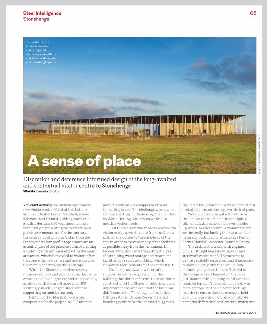
You can’t actually see Stonehenge from its new visitor centre. Not that this bothers architect Denton Corker Marshall, whose delicate, steel-framed building concludes English Heritage’s 30 year quest to �nd a better way of presenting the world famous prehistoric monument. On the contrary, the centre’s position some 2.1km from the Stones and its low pro�le appearance are an essential part of the practice’s aim of creating a building with minimal impact on the main attraction, which is revealed to visitors after they leave the new centre and move towards the monument through the landscape.
While the Stones themselves convey immense solidity and permanence, the visitor centre is all about lightness and transparency, achieved with the use of more than 300 strikingly slender, angled steel columns supporting an undulating roof.
Denton Corker Marshall won a fresh competition for the project in 2008 after its
previous scheme was scuppered by road tunnelling issues. The challenge was how to achieve a setting for Stonehenge that be�tted its World Heritage Site status while also meeting visitor needs.
First the decision was made to position the visitor centre some distance from the Stones at Airman’s Corner to the periphery of the site, in order to move as many of the facilities as possible away from the monument. In tandem with this came the architect’s idea of containing water storage and treatment facilities in a separate building, which simpli�ed requirements for the centre itself.
The next issue was how to create a suitably restrained expression for the building that didn’t reference the material or construction of the Stones. In addition, it was important to the architect that the building didn’t exceed the 7.4m height of the tallest trilithon stones. Denton Corker Marshall founding partner Barrie Marshall suggested
the pared-back concept of a waved roof atop a host of columns sheltering two distinct pods.
‘We didn’t want to put a structure in the landscape that felt static and rigid. A thin undulating canopy however implies lightness. Vertical columns wouldn’t work aesthetically but having them at a camber naturally pulls it all together,’ says Denton Corker Marshall associate Dominic Davey.
The architect worked with engineer Sinclair Knight Merz (now Jacobs) and steelwork contractor S H Structures to devise a suitably respectful, and if necessary removable, structure that would leave no lasting impact on the site. This led to the design of a raft foundation that was just 300mm thick, �oating on �ll over the retained top soil. This continuous slab was more appropriate than discrete footings in order to ensure that the canopy is held down in high winds, and also to mitigate potential di�erential settlements, which was
65
The RIBA Journal January 2015
The visitor centre is conceived as an undulating roof sheltering glazed (left) and structural insulated panel-clad (right) pods.
A sense of placeDiscretion and deference informed design of the long-awaited and contextual visitor centre to StonehengeWords Pamela Buxton
JAM
ES
O D
AVIE
S/E
NG
LIS
H H
ER
ITA
GE
65_BCSA_STONEHENGE_V2.indd 65 10/12/2014 15:24
The RIBA Journal January 2015
66 Steel IntelligenceStonehenge
particularly important given the north pod’s fully glazed facade.
Before choosing steel for the frame, the engineer considered timber with glulam spine beams, but found that the depth of the glulam would be too big for the lightness the architects were after. Having settled on steel instead for both the canopy and the myriad of columns because of its superior strength-to-weight ratio, the engineer used the pods to stabilise the structure.
‘We couldn’t let the roof swing around on slender columns without some other restraint so we used the pods themselves…If you weld the columns up to the canopy structure it acts like an inverted cantilever with the columns restraining the canopy and putting the horizontal load into the roof of the pod,’ said project director Paul Swainson.
The roof geometry was the key challenge. While meeting the architect’s vision for a lightweight undulating canopy, the engineer and steelwork contractor considered the need to standardise its fabrication and erection
as far as possible. The roof grillage was therefore oriented so that all the members lying parallel to the roof’s valley feature are straight, while those in the orthogonal direction are curved to a standard radius. In this way, the contours of the timber rafters plus associated deck and so t naturally follow the canopy’s single curvature.
One roof, two podsThe roof shelters two pods with independent steel-framed structures of beams and columns with bolted connections. The north pod is glazed with 795m2 of café and retail facilities incorporating discreetly positioned cross-bracing to stabilise the frame. The south pod is a 809m2 exhibition space with clear spans of up to 17.5m. The latter is clad with structural insulated panels that are designed to function as stressed-skin diaphragms to stabilise the steel frame by transferring lateral loads from the roof to the foundation. The roof is clad in zinc, with a perforated so t around the perimeter to deliberately
Having settled on steel for canopy and columns because of its superior strength-to-weight ratio, the engineer used the pods to stabilise the structure
32
5
1
6
0 5 25 50m
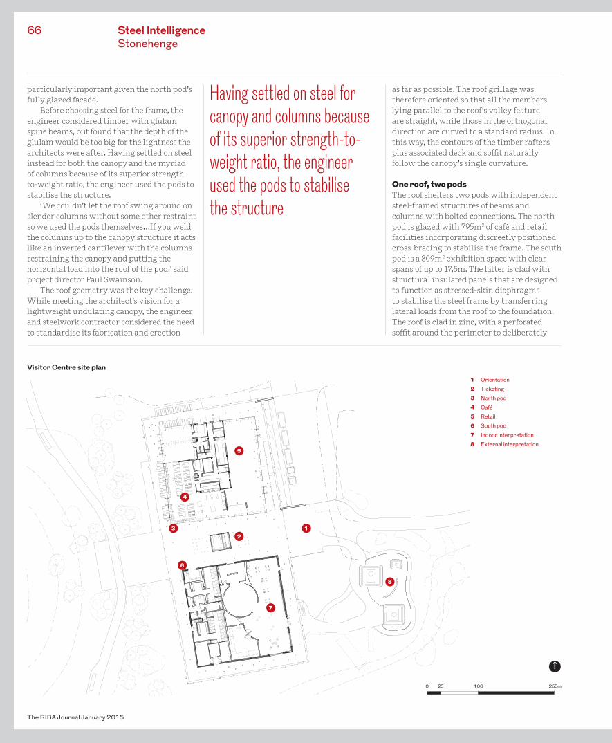
1 Orientation2 Ticketing3 North pod4 Café5 Retail6 South pod7 Indoor interpretation8 External interpretation
4
Visitor Centre site plan
7
8
0 25 100 250m
65_BCSA_STONEHENGE_V2.indd 66 10/12/2014 15:24
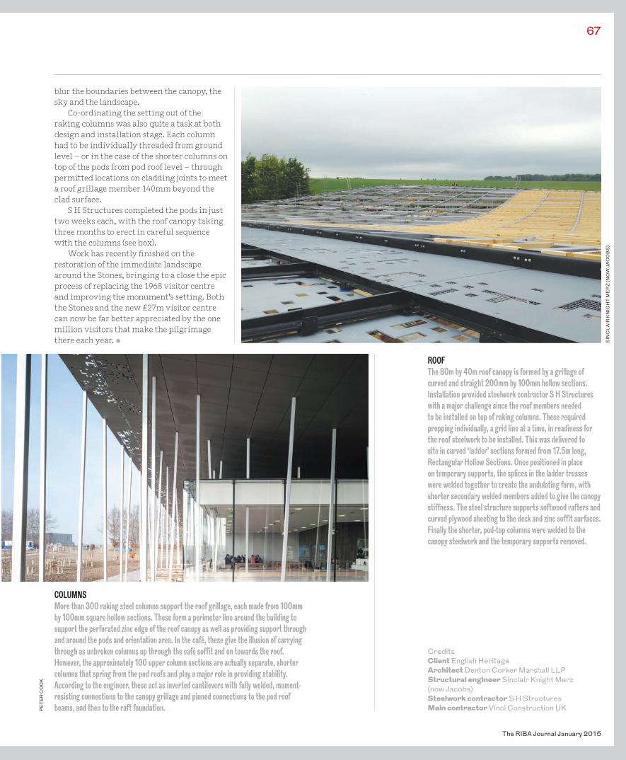
CreditsClient English HeritageArchitect Denton Corker Marshall LLPStructural engineer Sinclair Knight Merz (now Jacobs) Steelwork contractor S H StructuresMain contractor Vinci Construction UK
67
The RIBA Journal January 2015
blur the boundaries between the canopy, the sky and the landscape.
Co-ordinating the setting out of the raking columns was also quite a task at both design and installation stage. Each column had to be individually threaded from ground level – or in the case of the shorter columns on top of the pods from pod roof level – through permitted locations on cladding joints to meet a roof grillage member 140mm beyond the clad surface.
S H Structures completed the pods in just two weeks each, with the roof canopy taking three months to erect in careful sequence with the columns (see box).
Work has recently �nished on the restoration of the immediate landscape around the Stones, bringing to a close the epic process of replacing the 1968 visitor centre and improving the monument’s setting. Both the Stones and the new £27m visitor centre can now be far better appreciated by the one million visitors that make the pilgrimage there each year. •
ROOFThe 80m by 40m roof canopy is formed by a grillage of curved and straight 200mm by 100mm hollow sections. Installation provided steelwork contractor S H Structures with a major challenge since the roof members needed to be installed on top of raking columns. These required propping individually, a grid line at a time, in readiness for the roof steelwork to be installed. This was delivered to site in curved ‘ladder’ sections formed from 17.5m long, Rectangular Hollow Sections. Once positioned in place on temporary supports, the splices in the ladder trusses were welded together to create the undulating form, with shorter secondary welded members added to give the canopy stiffness. The steel structure supports softwood rafters and curved plywood sheeting to the deck and zinc soffit surfaces. Finally the shorter, pod-top columns were welded to the canopy steelwork and the temporary supports removed.
COLUMNSMore than 300 raking steel columns support the roof grillage, each made from 100mm by 100mm square hollow sections. These form a perimeter line around the building to support the perforated zinc edge of the roof canopy as well as providing support through and around the pods and orientation area. In the café, these give the illusion of carrying through as unbroken columns up through the café soffit and on towards the roof. However, the approximately 100 upper column sections are actually separate, shorter columns that spring from the pod roofs and play a major role in providing stability. According to the engineer, these act as inverted cantilevers with fully welded, moment-resisting connections to the canopy grillage and pinned connections to the pod roof beams, and then to the raft foundation.
SIN
CL
AIR
KN
IGH
T M
ER
Z (N
OW
JAC
OB
S)
PE
TE
R C
OO
K
65_BCSA_STONEHENGE_V2.indd 67 10/12/2014 15:24
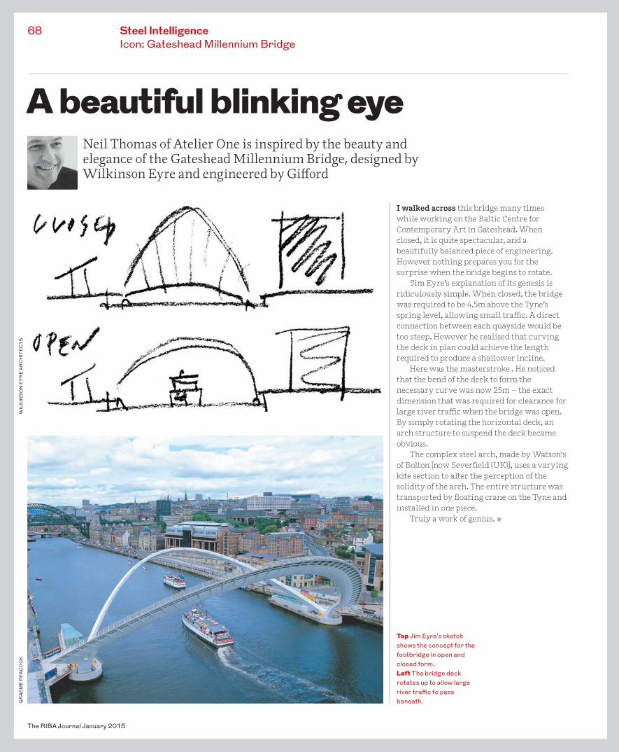
I walked across this bridge many times while working on the Baltic Centre for Contemporary Art in Gateshead. When closed, it is quite spectacular, and a beautifully balanced piece of engineering. However nothing prepares you for the surprise when the bridge begins to rotate.
Jim Eyre’s explanation of its genesis is ridiculously simple. When closed, the bridge was required to be 4.5m above the Tyne’s spring level, allowing small tra�c. A direct connection between each quayside would be too steep. However he realised that curving the deck in plan could achieve the length required to produce a shallower incline.
Here was the masterstroke . He noticed that the bend of the deck to form the necessary curve was now 25m – the exact dimension that was required for clearance for large river tra�c when the bridge was open. By simply rotating the horizontal deck, an arch structure to suspend the deck became obvious.
The complex steel arch, made by Watson’s of Bolton [now Sever�eld (UK)], uses a varying kite section to alter the perception of the solidity of the arch. The entire structure was transported by �oating crane on the Tyne and installed in one piece.
Truly a work of genius. •
The RIBA Journal January 2015
68 Steel IntelligenceIcon: Gateshead Millennium Bridge
GR
AE
ME
PE
ACO
CK
A beautiful blinking eye Neil Thomas of Atelier One is inspired by the beauty and elegance of the Gateshead Millennium Bridge, designed by Wilkinson Eyre and engineered by Gi�ord
Top Jim Eyre’s sketch shows the concept for the footbridge in open and closed form.Left The bridge deck rotates up to allow large river tra�c to pass beneath.
WIL
KIN
SO
N E
YR
E A
RC
HIT
EC
TS
XX_BCSA_GATESHEAD.indd 68 18/12/2014 13:25