Embed Size (px)
Citation preview
STEERING
C
D
E
SECTION STA
B
STEERING SYSTEM
F
H
I
J
K
L
M
T
N
O
P
CONTENTS
S
PRECAUTION ............................................... 2
PRECAUTIONS ................................................... 2Precaution for Supplemental Restraint System (SRS) "AIR BAG" and "SEAT BELT PRE-TEN-SIONER" ...................................................................2Precaution for Steering System ................................2
PREPARATION ............................................ 3
PREPARATION ................................................... 3Special Service Tool .................................................3Commercial Service Tool ..........................................4
SYMPTOM DIAGNOSIS ............................... 5
NOISE, VIBRATION AND HARSHNESS (NVH) TROUBLESHOOTING ............................. 5
NVH Troubleshooting Chart ......................................5
ON-VEHICLE MAINTENANCE ..................... 6
POWER STEERING FLUID ................................ 6Checking Fluid Level .................................................6Checking Fluid Leakage ............................................6Air Bleeding Hydraulic System ..................................6
ON-VEHICLE REPAIR .................................. 8
STEERING WHEEL ............................................. 8On-Vehicle Inspection and Service ...........................8
POWER STEERING OIL PUMP .........................10On-Vehicle Inspection and Service .........................10
REMOVAL AND INSTALLATION ...............11
STEERING WHEEL ............................................11Removal and Installation .........................................11
STEERING COLUMN ........................................12Removal and Installation .........................................12
POWER STEERING GEAR AND LINKAGE ....15Removal and Installation .........................................15
POWER STEERING OIL PUMP .......................17Component ..............................................................17Removal and Installation .........................................18
HYDRAULIC LINE ............................................19Removal and Installation .........................................19
DISASSEMBLY AND ASSEMBLY ..............20
STEERING COLUMN ........................................20Disassembly and Assembly .....................................20
POWER STEERING OIL PUMP .......................22Component ..............................................................22Disassembly and Assembly .....................................24
STEERING GEAR AND LINKAGE ...................26Disassembly and Assembly .....................................26
SERVICE DATA AND SPECIFICATIONS (SDS) ............................................................29
SERVICE DATA AND SPECIFICATIONS (SDS) .................................................................29
Steering Wheel ........................................................29Steering Column ......................................................29Steering Gear Outer and Inner Socket ....................29Tie-rod .....................................................................30Oil Pump ..................................................................30Steering Fluid ..........................................................30
ST-1

PRECAUTIONS
< PRECAUTION >PRECAUTIONPRECAUTIONS
Precaution for Supplemental Restraint System (SRS) "AIR BAG" and "SEAT BELT PRE-TENSIONER" INFOID:0000000003221363
The Supplemental Restraint System such as “AIR BAG” and “SEAT BELT PRE-TENSIONER”, used alongwith a front seat belt, helps to reduce the risk or severity of injury to the driver and front passenger for certaintypes of collision. This system includes seat belt switch inputs and dual stage front air bag modules. The SRSsystem uses the seat belt switches to determine the front air bag deployment, and may only deploy one frontair bag, depending on the severity of a collision and whether the front occupants are belted or unbelted.Information necessary to service the system safely is included in the SR and SB section of this Service Man-ual.WARNING:• To avoid rendering the SRS inoperative, which could increase the risk of personal injury or death in
the event of a collision which would result in air bag inflation, all maintenance must be performed byan authorized NISSAN/INFINITI dealer.
• Improper maintenance, including incorrect removal and installation of the SRS, can lead to personalinjury caused by unintentional activation of the system. For removal of Spiral Cable and Air BagModule, see the SR section.
• Do not use electrical test equipment on any circuit related to the SRS unless instructed to in thisService Manual. SRS wiring harnesses can be identified by yellow and/or orange harnesses or har-ness connectors.
Precaution for Steering System INFOID:0000000003221364
• Before disassembly, thoroughly clean the outside of the unit.• Disassembly should be done in a clean work area. It is important to prevent the internal parts from becoming
contaminated by dirt or other foreign matter.• For easier and proper assembly, place disassembled parts in order on a parts rack.• Use nylon cloth or paper towels to clean the parts; common shop rags can leave lint that might interfere with
their operation. • Before inspection or reassembly, carefully clean all parts with a general purpose, non-flammable solvent.• Before assembly, apply a coat of recommended Genuine NISSAN PSF or equivalent to hydraulic parts.
Petroleum jelly may be applied to O-rings and seals. Do not use any grease.• Replace all gaskets, seals and O-rings. Avoid damaging O-rings, seals and gaskets during installation. Per-
form functional tests whenever designated.
ST-2

PREPARATION
C
D
E
F
H
I
J
K
L
M
A
B
T
N
O
P
< PREPARATION >
S
PREPARATIONPREPARATION
Special Service Tool INFOID:0000000003221365
The actual shapes of Kent-Moore tools may differ from those of special service tools illustrated here.
Tool number(Kent-Moore No.)Tool name
Description
ST3127 S000(See J-25765-A)Preload gauge 1. GG9103000 (J-25765-A) Torque wrench 2. HT62940000 ( — ) Socket adapter 3. HT62900000 ( — ) Socket adapter
Inspecting of pinion rotating torque and rota-tional torque for ball joint
HT72520000(J-25730-A)Ball joint remover
Removing steering outer socket
1. KV48105300-4 and 5295262U10( — )Connector A and O-ring2. KV48105300-3 and 5295262U00( — )Eye-bolt and O-ring3. KV48103500(J-26357 and J-26357-10)Pressure gauge and shut-off valve4. KV48105300-1 and 5295262U00( — )Connector B and O-ring5. KV48105300-2( — )Nut
Measuring oil pump relief pressure
—(J-44372)Spring gauge
Measuring steering wheel turning force
KV40107300( — )
Crimping boot bands
S-NT541
NT146
SGIA0427E
LST024
ZZA1229D
ST-3
PREPARATION
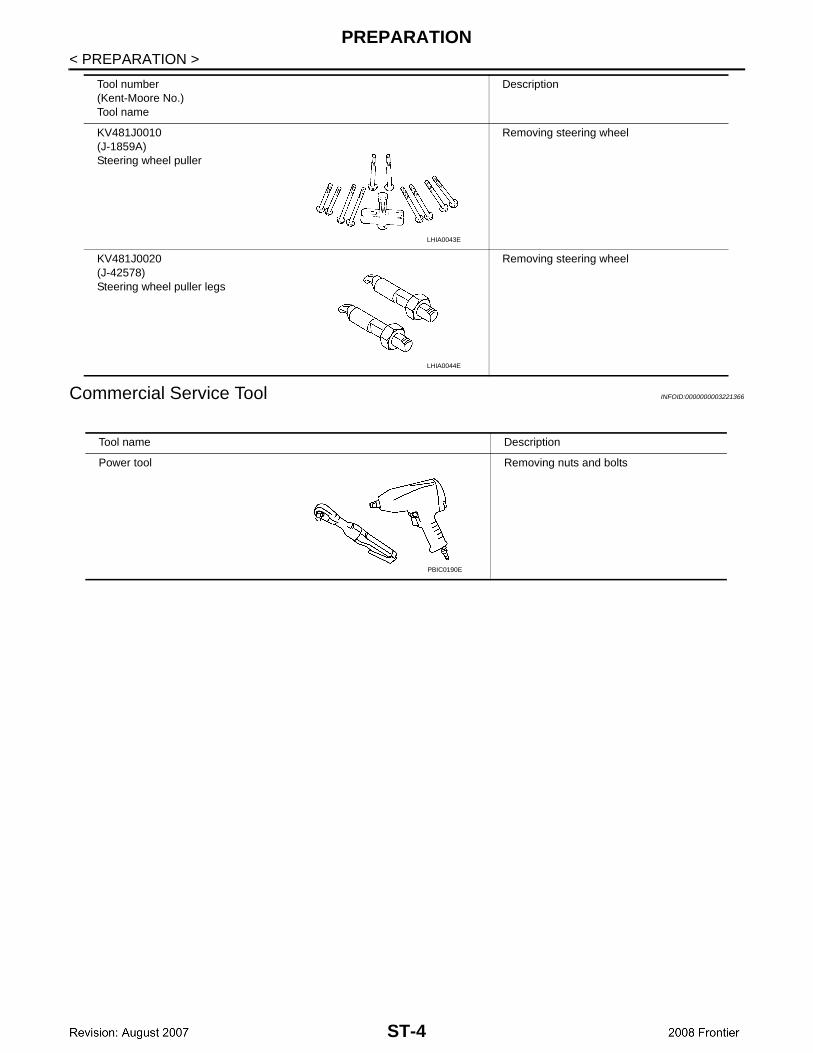
< PREPARATION >Commercial Service Tool INFOID:0000000003221366
KV481J0010 (J-1859A)Steering wheel puller
Removing steering wheel
KV481J0020(J-42578)Steering wheel puller legs
Removing steering wheel
Tool number(Kent-Moore No.)Tool name
Description
LHIA0043E
LHIA0044E
Tool name Description
Power tool Removing nuts and bolts
PBIC0190E
ST-4

NOISE, VIBRATION AND HARSHNESS (NVH) TROUBLESHOOTING
C
D
E
F
H
I
J
K
L
M
A
B
T
N
O
P
< SYMPTOM DIAGNOSIS >
S
SYMPTOM DIAGNOSISNOISE, VIBRATION AND HARSHNESS (NVH) TROUBLESHOOTING
NVH Troubleshooting Chart INFOID:0000000003303124
Use chart below to help you find the cause of the symptom. If necessary, repair or replace these parts.
×: Applicable
Reference page
ST-
6
ST-
6
ST-
26
ST-
26
ST-
26
ST-
6
ST-
8
ST-
8
EM
-14,
"C
heck
ing
Driv
e B
elt"
(Q
R25
DE
),E
M-1
23, "
Che
ckin
g D
rive
Bel
ts"
(VQ
40D
E)
ST-
8
ST-
12
ST-
15
ST-
12
ST-
12
ST-
15
DLN
-128
, "N
VH
Tro
uble
shoo
ting
Cha
rt"
DLN
-172
, "N
VH
Tro
uble
shoo
ting
Cha
rt"
FAX
-4, "
NV
H T
roub
lesh
ootin
g C
hart
"
FS
U-4
, "N
VH
Tro
uble
shoo
ting
Cha
rt"
WT-
30, "
NV
H T
roub
lesh
ootin
g C
hart
"
WT-
30, "
NV
H T
roub
lesh
ootin
g C
hart
"
FAX
-4, "
NV
H T
roub
lesh
ootin
g C
hart
"
BR
-5, "
NV
H T
roub
lesh
ootin
g C
hart
"
Possible cause and suspected parts
Flu
id le
vel
Air
in h
ydra
ulic
sys
tem
Out
er s
ocke
t bal
l joi
nt s
win
ging
forc
e
Out
er s
ocke
t bal
l joi
nt r
otat
ing
torq
ue
Out
er s
ocke
t bal
l joi
nt e
nd p
lay
Ste
erin
g flu
id le
akag
e
Ste
erin
g w
heel
pla
y
Ste
erin
g ge
ar r
ack
slid
ing
forc
e
Driv
e be
lt lo
osen
ess
Impr
oper
ste
erin
g w
heel
Impr
oper
inst
alla
tion
or lo
osen
ess
of ti
lt lo
ck le
ver
Mou
ntin
g ru
bber
det
erio
ratio
n
Ste
erin
g co
lum
n de
form
atio
n or
dam
age
Impr
oper
inst
alla
tion
or lo
osen
ess
of s
teer
ing
colu
mn
Ste
erin
g lin
kage
loos
enes
s
PR
OP
ELL
ER
SH
AF
T
DIF
FE
RE
NT
IAL
AX
LE
SU
SP
EN
SIO
N
TIR
ES
RO
AD
WH
EE
L
DR
IVE
SH
AF
T
BR
AK
ES
Symptom
Noise × × × × × × × × × × × × × × × × ×
Shake × × × × × × × × × ×
Vibration × × × × × × × × × ×
Shimmy × × × × × × × × ×
Shudder × × × × × × ×
ST-5

POWER STEERING FLUID
< ON-VEHICLE MAINTENANCE >ON-VEHICLE MAINTENANCEPOWER STEERING FLUID
Checking Fluid Level INFOID:0000000003303125
Check fluid level, referring to the scale on the reservoir tank.Use HOT range for fluid temperatures of 50° – 80°C (122° – 176°F).Use COLD range for fluid temperatures of 0° – 30°C (32° – 86°F).CAUTION:• Do not overfill.• Do not reuse any power steering fluid.• Recommended fluid is Genuine NISSAN PSF or equivalent.
Refer to MA-12.
Checking Fluid Leakage INFOID:0000000003303126
Check the hydraulic piping lines for improper attachment, leaks,cracks, damage, loose connections, chafing and deterioration.CAUTION:Do not reuse copper washers.1. Run the engine until the fluid temperature reaches 50° – 80°C
(122° – 176°F) in the reservoir tank. Keep engine speed idle.CAUTION:Do not allow steering fluid reservoir tank to go below theMIN level line. Check tank frequently and add fluid asneeded.
2. Turn the steering wheel to the right and left several times.3. Hold the steering wheel at each “locked” position for five sec-
onds to check for fluid leakage.CAUTION:Do not hold steering wheel in the locked position for more than 10 seconds. (There is the possibil-ity that the oil pump may be damaged.)
4. If fluid leakage at a connection is noticed, loosen the connection and then retighten. Do not over-tightenconnector as this can damage O-ring, washer and connector. Refer to ST-10 and ST-19.
5. If fluid leakage from the oil pump is noticed, check the oil pump. Refer to ST-10.6. Check steering gear boots for accumulation of fluid, indicating a leak from the steering gear.
Air Bleeding Hydraulic System INFOID:0000000003303127
Incomplete air bleeding causes the following:• Air bubbles in reservoir tank• Clicking noise in oil pump• Excessive buzzing in oil pumpWhen this happens bleed the air again.NOTE:When the vehicle is stationary or while the steering wheel is being turned slowly, some noise may be heardfrom the oil pump or gear. This noise is normal and does not affect any system.1. Check for fluid leakage. Refer to ST-6, "Checking Fluid Leakage".2. Start the engine and turn the steering wheel fully to the right and left several times.
CAUTION:Do not allow steering fluid reservoir tank to go below the MIN level line. Check tank frequently andadd fluid as needed.
3. Run the engine at idle speed. Hold the steering wheel at each "locked" position for three seconds.CAUTION:
LGIA0021E
SGIA0506E
ST-6

POWER STEERING FLUID
C
D
E
F
H
I
J
K
L
M
A
B
T
N
O
P
< ON-VEHICLE MAINTENANCE >
S
Do not hold steering wheel in the locked position for more than 10 seconds. (There is the possibil-ity that oil pump may be damaged.)
4. Repeat step 3 several times at about three second intervals. 5. Check for air bubbles, cloudy fluid and fluid leakage.6. If air bubbles or cloudiness exists, perform steps 3 and 4 again until air bubbles and cloudiness do not
exist.7. Stop the engine and check fluid level.
ST-7
STEERING WHEEL
< ON-VEHICLE REPAIR >ON-VEHICLE REPAIRSTEERING WHEEL
On-Vehicle Inspection and Service INFOID:0000000003303132
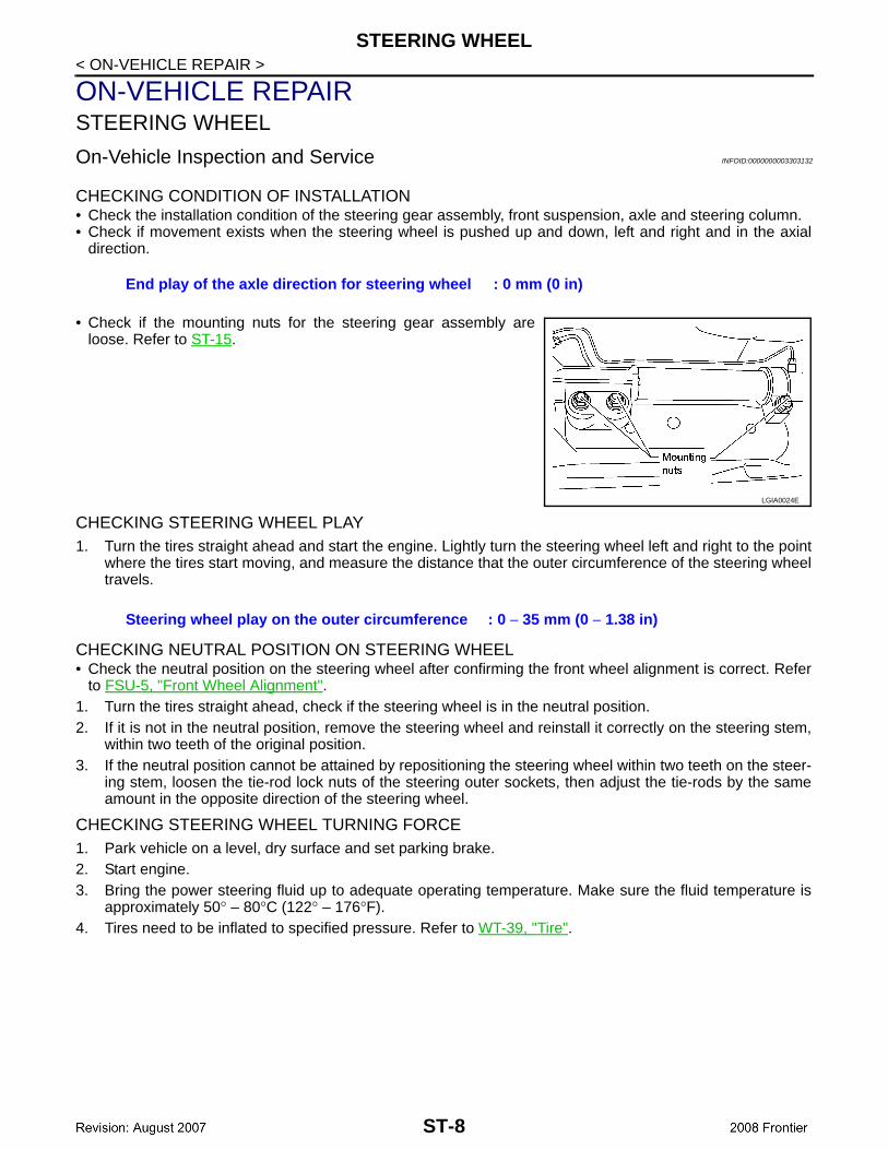
CHECKING CONDITION OF INSTALLATION• Check the installation condition of the steering gear assembly, front suspension, axle and steering column.• Check if movement exists when the steering wheel is pushed up and down, left and right and in the axial
direction.
• Check if the mounting nuts for the steering gear assembly areloose. Refer to ST-15.
CHECKING STEERING WHEEL PLAY1. Turn the tires straight ahead and start the engine. Lightly turn the steering wheel left and right to the point
where the tires start moving, and measure the distance that the outer circumference of the steering wheeltravels.
CHECKING NEUTRAL POSITION ON STEERING WHEEL• Check the neutral position on the steering wheel after confirming the front wheel alignment is correct. Refer
to FSU-5, "Front Wheel Alignment".1. Turn the tires straight ahead, check if the steering wheel is in the neutral position.2. If it is not in the neutral position, remove the steering wheel and reinstall it correctly on the steering stem,
within two teeth of the original position. 3. If the neutral position cannot be attained by repositioning the steering wheel within two teeth on the steer-
ing stem, loosen the tie-rod lock nuts of the steering outer sockets, then adjust the tie-rods by the sameamount in the opposite direction of the steering wheel.
CHECKING STEERING WHEEL TURNING FORCE1. Park vehicle on a level, dry surface and set parking brake.2. Start engine.3. Bring the power steering fluid up to adequate operating temperature. Make sure the fluid temperature is
approximately 50° – 80°C (122° – 176°F).4. Tires need to be inflated to specified pressure. Refer to WT-39, "Tire".
End play of the axle direction for steering wheel : 0 mm (0 in)
LGIA0024E
Steering wheel play on the outer circumference : 0 − 35 mm (0 − 1.38 in)
ST-8
STEERING WHEEL
C
D
E
F
H
I
J
K
L
M
A
B
T
N
O
P
< ON-VEHICLE REPAIR >
S
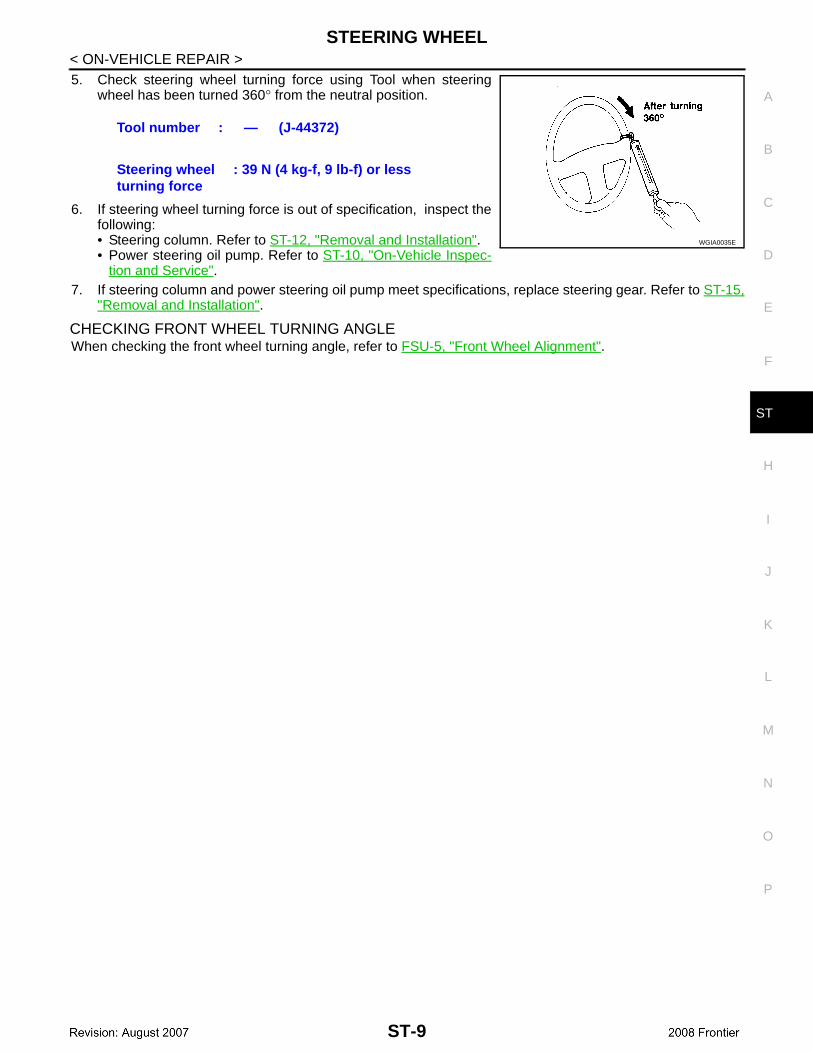
5. Check steering wheel turning force using Tool when steeringwheel has been turned 360° from the neutral position.
6. If steering wheel turning force is out of specification, inspect thefollowing:• Steering column. Refer to ST-12, "Removal and Installation".• Power steering oil pump. Refer to ST-10, "On-Vehicle Inspec-
tion and Service".7. If steering column and power steering oil pump meet specifications, replace steering gear. Refer to ST-15,
"Removal and Installation".
CHECKING FRONT WHEEL TURNING ANGLE When checking the front wheel turning angle, refer to FSU-5, "Front Wheel Alignment".
Tool number : — (J-44372)
Steering wheel turning force
: 39 N (4 kg-f, 9 lb-f) or less
WGIA0035E
ST-9
POWER STEERING OIL PUMP
< ON-VEHICLE REPAIR >POWER STEERING OIL PUMP
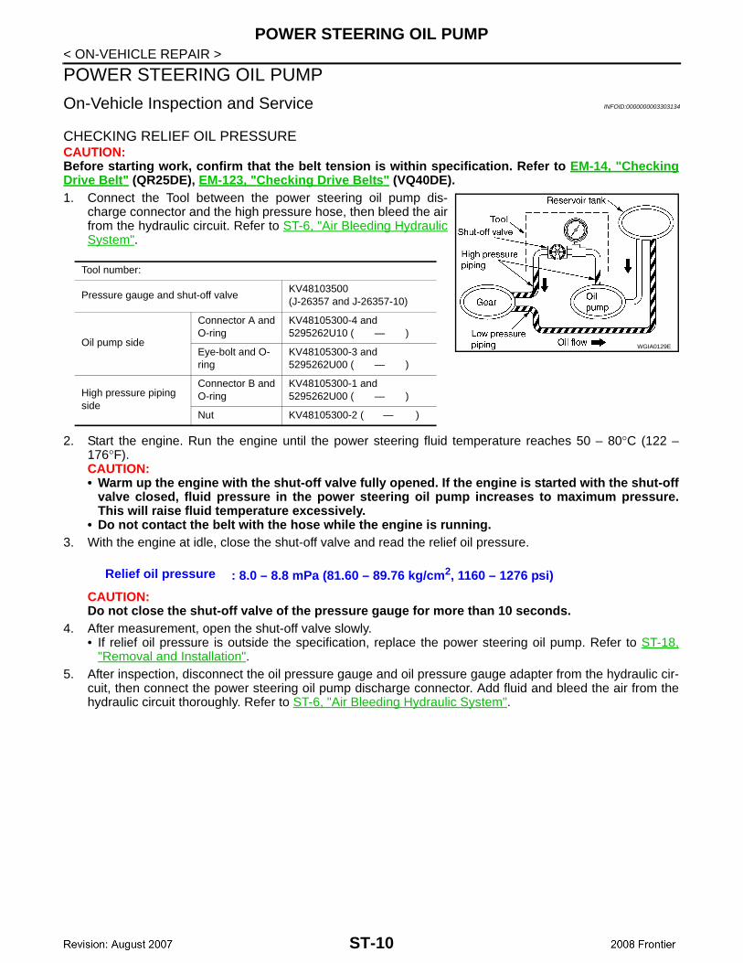
On-Vehicle Inspection and Service INFOID:0000000003303134
CHECKING RELIEF OIL PRESSURECAUTION:Before starting work, confirm that the belt tension is within specification. Refer to EM-14, "CheckingDrive Belt" (QR25DE), EM-123, "Checking Drive Belts" (VQ40DE).1. Connect the Tool between the power steering oil pump dis-
charge connector and the high pressure hose, then bleed the airfrom the hydraulic circuit. Refer to ST-6, "Air Bleeding HydraulicSystem".
2. Start the engine. Run the engine until the power steering fluid temperature reaches 50 – 80°C (122 –176°F).CAUTION:• Warm up the engine with the shut-off valve fully opened. If the engine is started with the shut-off
valve closed, fluid pressure in the power steering oil pump increases to maximum pressure.This will raise fluid temperature excessively.
• Do not contact the belt with the hose while the engine is running.3. With the engine at idle, close the shut-off valve and read the relief oil pressure.
CAUTION:Do not close the shut-off valve of the pressure gauge for more than 10 seconds.
4. After measurement, open the shut-off valve slowly.• If relief oil pressure is outside the specification, replace the power steering oil pump. Refer to ST-18,
"Removal and Installation".5. After inspection, disconnect the oil pressure gauge and oil pressure gauge adapter from the hydraulic cir-
cuit, then connect the power steering oil pump discharge connector. Add fluid and bleed the air from thehydraulic circuit thoroughly. Refer to ST-6, "Air Bleeding Hydraulic System".
Tool number:
Pressure gauge and shut-off valveKV48103500(J-26357 and J-26357-10)
Oil pump side
Connector A and O-ring
KV48105300-4 and 5295262U10 ( — )
Eye-bolt and O-ring
KV48105300-3 and 5295262U00 ( — )
High pressure piping side
Connector B and O-ring
KV48105300-1 and 5295262U00 ( — )
Nut KV48105300-2 ( — )
WGIA0129E
Relief oil pressure : 8.0 – 8.8 mPa (81.60 – 89.76 kg/cm2, 1160 – 1276 psi)
ST-10
STEERING WHEEL
C
D
E
F
H
I
J
K
L
M
A
B
T
N
O
P
< REMOVAL AND INSTALLATION >
S
REMOVAL AND INSTALLATIONSTEERING WHEEL
Removal and Installation INFOID:0000000003303133
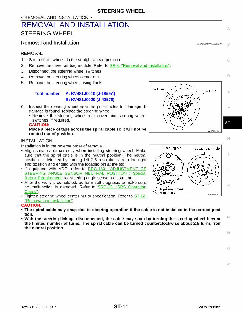
REMOVAL1. Set the front wheels in the straight-ahead position.2. Remove the driver air bag module. Refer to SR-4, "Removal and Installation".3. Disconnect the steering wheel switches.4. Remove the steering wheel center nut.5. Remove the steering wheel, using Tools.
6. Inspect the steering wheel near the puller holes for damage. Ifdamage is found, replace the steering wheel.• Remove the steering wheel rear cover and steering wheel
switches, if required.CAUTION:Place a piece of tape across the spiral cable so it will not berotated out of position.
INSTALLATIONInstallation is in the reverse order of removal.• Align spiral cable correctly when installing steering wheel. Make
sure that the spiral cable is in the neutral position. The neutralposition is detected by turning left 2.6 revolutions from the rightend position and ending with the locating pin at the top.
• If equipped with VDC, refer to BRC-163, "ADJUSTMENT OFSTEERING ANGLE SENSOR NEUTRAL POSITION : SpecialRepair Requirement" for steering angle sensor adjustment.
• After the work is completed, perform self-diagnosis to make sureno malfunction is detected. Refer to SRC-13, "SRS OperationCheck".
• Tighten steering wheel center nut to specification. Refer to ST-12,"Removal and Installation".
CAUTION:• The spiral cable may snap due to steering operation if the cable is not installed in the correct posi-
tion.• With the steering linkage disconnected, the cable may snap by turning the steering wheel beyond
the limited number of turns. The spiral cable can be turned counterclockwise about 2.5 turns fromthe neutral position.
Tool number A: KV481J0010 (J-1859A)B: KV481J0020 (J-42578)
WHIA0124E
PHIA0275E
ST-11

STEERING COLUMN
< REMOVAL AND INSTALLATION >STEERING COLUMN
Removal and Installation INFOID:0000000003303138
CAUTION:• Do not exert any axial load or impact to the steering column.• Do not move the steering gear while the steering column assembly is removed.
REMOVAL1. Remove the spiral cable with the combination switches attached from the steering column assembly.
Refer to SR-6, "Removal and Installation".2. Remove the lower instrument panel LH. Refer to IP-10, "Exploded View".3. Remove the steering column cover and ignition key finisher. Refer to IP-10, "Exploded View".4. Remove the lower knee protector. Refer to IP-10, "Exploded View".
1. Driver air bag module 2. Steering wheel center nut 3. Steering wheel
4. Combination switch and spiral cable 5. Steering column assembly and igni-tion switch
6. Collar
7. Hole cover seal 8. Clamp 9. Hole cover mounting plate
10. Hole cover 11. Upper joint 12. Upper shaft
13. Boot clamp 14. Lower joint shaft 15. Boot and clips (plastic)
WGIA0125E
ST-12
STEERING COLUMN
C
D
E
F
H
I
J
K
L
M
A
B
T
N
O
P
< REMOVAL AND INSTALLATION >
S
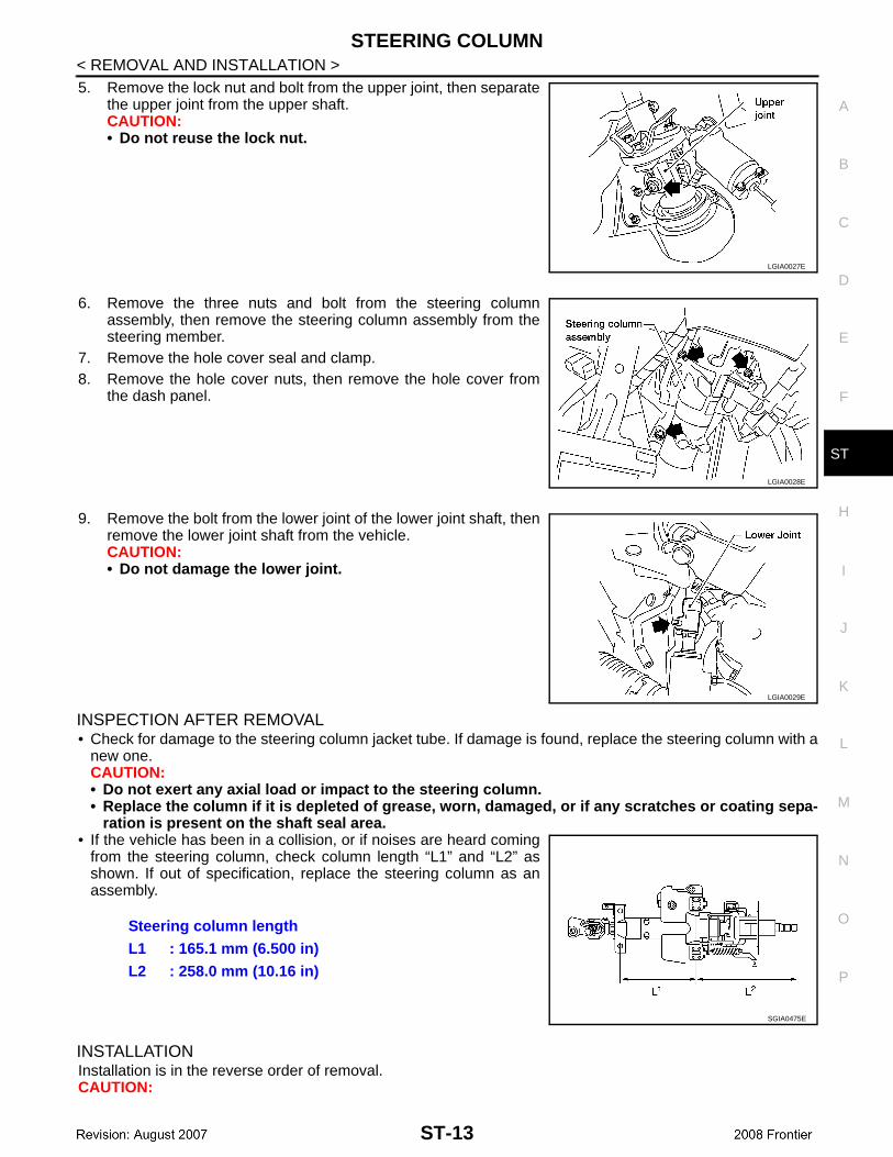
5. Remove the lock nut and bolt from the upper joint, then separatethe upper joint from the upper shaft.CAUTION:• Do not reuse the lock nut.
6. Remove the three nuts and bolt from the steering columnassembly, then remove the steering column assembly from thesteering member.
7. Remove the hole cover seal and clamp.8. Remove the hole cover nuts, then remove the hole cover from
the dash panel.
9. Remove the bolt from the lower joint of the lower joint shaft, thenremove the lower joint shaft from the vehicle.CAUTION:• Do not damage the lower joint.
INSPECTION AFTER REMOVAL• Check for damage to the steering column jacket tube. If damage is found, replace the steering column with a
new one.CAUTION:• Do not exert any axial load or impact to the steering column.• Replace the column if it is depleted of grease, worn, damaged, or if any scratches or coating sepa-
ration is present on the shaft seal area.• If the vehicle has been in a collision, or if noises are heard coming
from the steering column, check column length “L1” and “L2” asshown. If out of specification, replace the steering column as anassembly.
INSTALLATIONInstallation is in the reverse order of removal.CAUTION:
LGIA0027E
LGIA0028E
LGIA0029E
Steering column lengthL1 : 165.1 mm (6.500 in)L2 : 258.0 mm (10.16 in)
SGIA0475E
ST-13
STEERING COLUMN
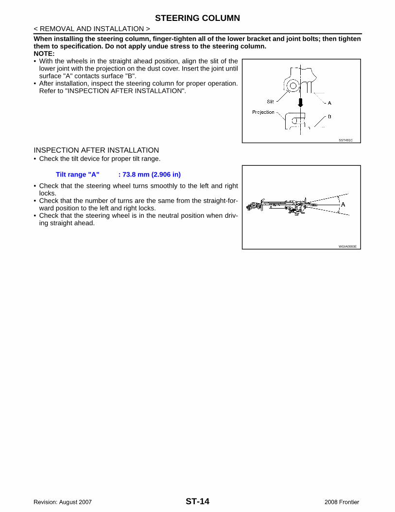
< REMOVAL AND INSTALLATION >When installing the steering column, finger-tighten all of the lower bracket and joint bolts; then tightenthem to specification. Do not apply undue stress to the steering column.NOTE:• With the wheels in the straight ahead position, align the slit of thelower joint with the projection on the dust cover. Insert the joint untilsurface "A" contacts surface "B".
• After installation, inspect the steering column for proper operation.Refer to "INSPECTION AFTER INSTALLATION".
INSPECTION AFTER INSTALLATION• Check the tilt device for proper tilt range.
• Check that the steering wheel turns smoothly to the left and rightlocks.
• Check that the number of turns are the same from the straight-for-ward position to the left and right locks.
• Check that the steering wheel is in the neutral position when driv-ing straight ahead.
SST491C
Tilt range "A" : 73.8 mm (2.906 in)
WGIA0083E
ST-14
POWER STEERING GEAR AND LINKAGE
C
D
E
F
H
I
J
K
L
M
A
B
T
N
O
P
< REMOVAL AND INSTALLATION >
S
POWER STEERING GEAR AND LINKAGE
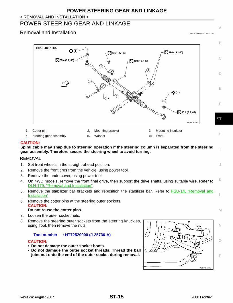
Removal and Installation INFOID:0000000003303139
CAUTION:Spiral cable may snap due to steering operation if the steering column is separated from the steeringgear assembly. Therefore secure the steering wheel to avoid turning.
REMOVAL1. Set front wheels in the straight-ahead position.2. Remove the front tires from the vehicle, using power tool.3. Remove the undercover, using power tool.4. On 4WD models, remove the front final drive, then support the drive shafts, using suitable wire. Refer to
DLN-179, "Removal and Installation".5. Remove the stabilizer bar brackets and reposition the stabilizer bar. Refer to FSU-14, "Removal and
Installation".6. Remove the cotter pins at the steering outer sockets.
CAUTION:Do not reuse the cotter pins.
7. Loosen the outer socket nuts.8. Remove the steering outer sockets from the steering knuckles,
using Tool, then remove the nuts.
CAUTION:• Do not damage the outer socket boots.• Do not damage the outer socket threads. Thread the ball
joint nut onto the end of the outer socket during removal.
1. Cotter pin 2. Mounting bracket 3. Mounting insulator
4. Steering gear assembly 5. Washer ⇐ Front
WGIA0170E
Tool number : HT72520000 (J-25730-A)
WGIA0130E
ST-15

POWER STEERING GEAR AND LINKAGE
< REMOVAL AND INSTALLATION >9. Remove the high-pressure and low-pressure piping from thesteering gear assembly, then drain the fluid from the piping.
10. Remove the bolt from the lower joint of the lower joint shaft, thenseparate the lower joint from the steering gear assembly.CAUTION:• Do not damage the lower joint.
11. Remove the nuts and bolts of the steering gear assembly, usingpower tool, then remove the steering gear assembly from thevehicle.
INSTALLATIONInstallation is in the reverse order of removal.• With the steering wheel in the straight ahead position, align the slit
of the lower joint with the projection on the dust cover. Insert thejoint until surface "A" contacts surface "B".
• After removing/installing or replacing steering components, checkwheel alignment. Refer to FSU-5, "Front Wheel Alignment".
• After adjusting wheel alignment, adjust neutral position of thesteering angle sensor. Refer to BRC-163, "ADJUSTMENT OFSTEERING ANGLE SENSOR NEUTRAL POSITION : SpecialRepair Requirement".
• Bleed the air from the steering hydraulic system. Refer to ST-6,"Air Bleeding Hydraulic System".
INSPECTION AFTER INSTALLATION• Check that the steering wheel turns smoothly to the left and right locks.• Check that the number of turns are the same from the straight-forward position to the left and right locks.• Check that the steering wheel is in the neutral position when driving straight ahead.
LGIA0032E
LGIA0029E
LGIA0024E
SST491C
ST-16
POWER STEERING OIL PUMP
C
D
E
F
H
I
J
K
L
M
A
B
T
N
O
P
< REMOVAL AND INSTALLATION >
S
POWER STEERING OIL PUMP
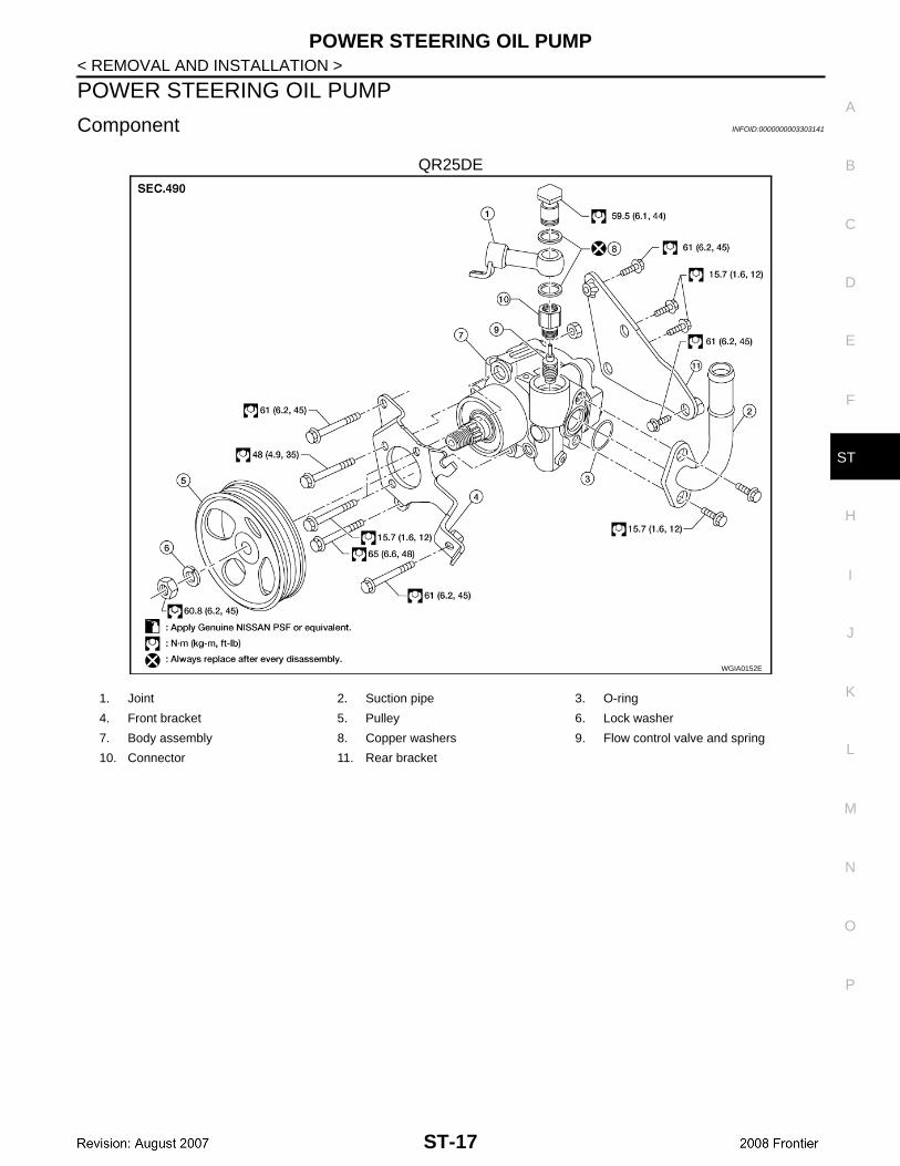
Component INFOID:0000000003303141
QR25DE
WGIA0152E
1. Joint 2. Suction pipe 3. O-ring
4. Front bracket 5. Pulley 6. Lock washer
7. Body assembly 8. Copper washers 9. Flow control valve and spring
10. Connector 11. Rear bracket
ST-17
POWER STEERING OIL PUMP
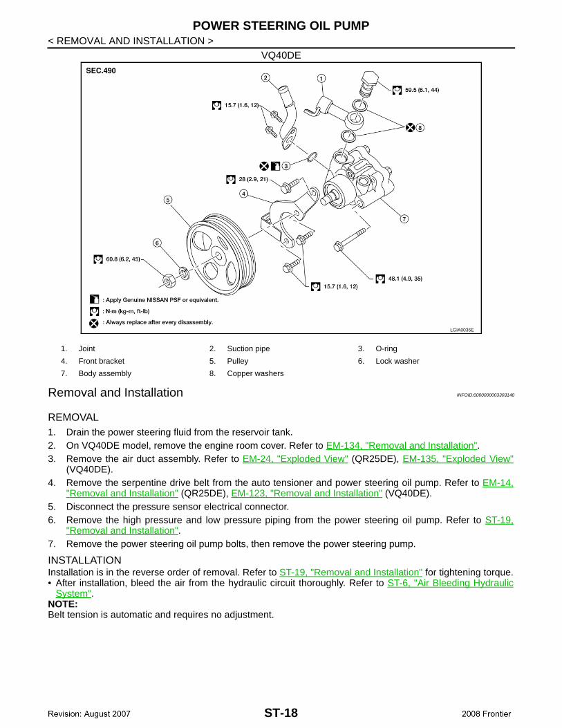
< REMOVAL AND INSTALLATION >VQ40DE
Removal and Installation INFOID:0000000003303140
REMOVAL1. Drain the power steering fluid from the reservoir tank.2. On VQ40DE model, remove the engine room cover. Refer to EM-134, "Removal and Installation".3. Remove the air duct assembly. Refer to EM-24, "Exploded View" (QR25DE), EM-135, "Exploded View"
(VQ40DE).4. Remove the serpentine drive belt from the auto tensioner and power steering oil pump. Refer to EM-14,
"Removal and Installation" (QR25DE), EM-123, "Removal and Installation" (VQ40DE).5. Disconnect the pressure sensor electrical connector.6. Remove the high pressure and low pressure piping from the power steering oil pump. Refer to ST-19,
"Removal and Installation".7. Remove the power steering oil pump bolts, then remove the power steering pump.
INSTALLATIONInstallation is in the reverse order of removal. Refer to ST-19, "Removal and Installation" for tightening torque.• After installation, bleed the air from the hydraulic circuit thoroughly. Refer to ST-6, "Air Bleeding Hydraulic
System".NOTE:Belt tension is automatic and requires no adjustment.
LGIA0036E
1. Joint 2. Suction pipe 3. O-ring
4. Front bracket 5. Pulley 6. Lock washer
7. Body assembly 8. Copper washers
ST-18
HYDRAULIC LINE
C
D
E
F
H
I
J
K
L
M
A
B
T
N
O
P
< REMOVAL AND INSTALLATION >
S
HYDRAULIC LINE
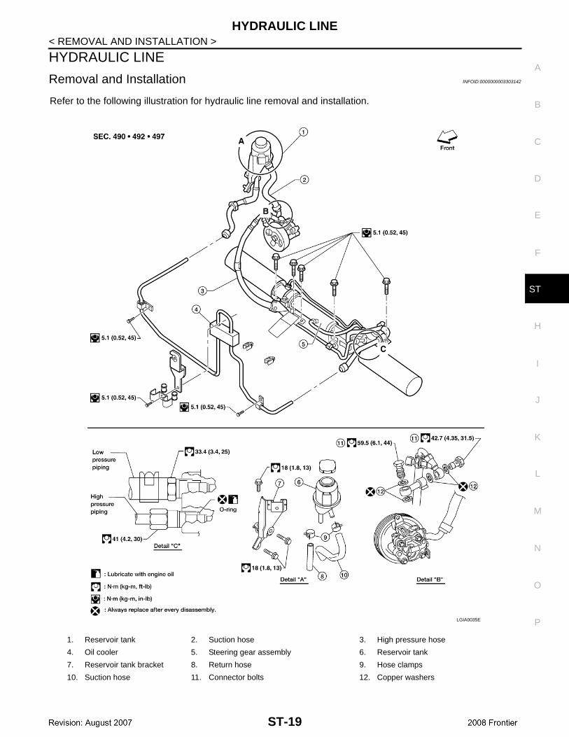
Removal and Installation INFOID:0000000003303142
Refer to the following illustration for hydraulic line removal and installation.
1. Reservoir tank 2. Suction hose 3. High pressure hose
4. Oil cooler 5. Steering gear assembly 6. Reservoir tank
7. Reservoir tank bracket 8. Return hose 9. Hose clamps
10. Suction hose 11. Connector bolts 12. Copper washers
LGIA0035E
ST-19
STEERING COLUMN
< DISASSEMBLY AND ASSEMBLY >DISASSEMBLY AND ASSEMBLYSTEERING COLUMN
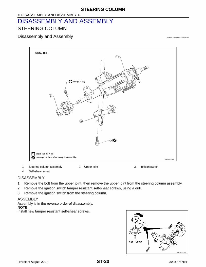
Disassembly and Assembly INFOID:0000000003303143
DISASSEMBLY1. Remove the bolt from the upper joint, then remove the upper joint from the steering column assembly.2. Remove the ignition switch tamper resistant self-shear screws, using a drill.3. Remove the ignition switch from the steering column.
ASSEMBLYAssembly is in the reverse order of disassembly.NOTE:Install new tamper resistant self-shear screws.
1. Steering column assembly 2. Upper joint 3. Ignition switch
4. Self-shear screw
WGIA0126E
WGIA0009E
ST-20
STEERING COLUMN
C
D
E
F
H
I
J
K
L
M
A
B
T
N
O
P
< DISASSEMBLY AND ASSEMBLY >
S
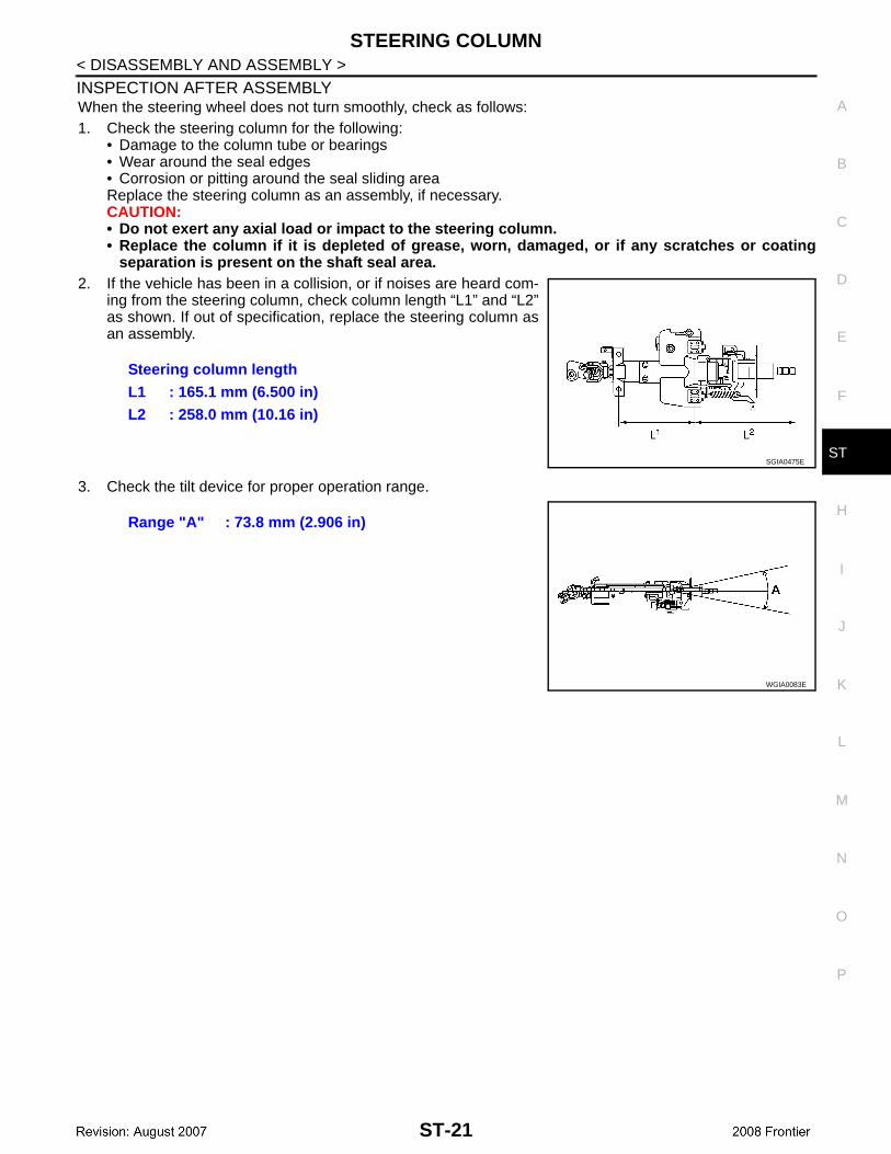
INSPECTION AFTER ASSEMBLYWhen the steering wheel does not turn smoothly, check as follows:1. Check the steering column for the following:
• Damage to the column tube or bearings• Wear around the seal edges• Corrosion or pitting around the seal sliding areaReplace the steering column as an assembly, if necessary.CAUTION:• Do not exert any axial load or impact to the steering column.• Replace the column if it is depleted of grease, worn, damaged, or if any scratches or coating
separation is present on the shaft seal area.2. If the vehicle has been in a collision, or if noises are heard com-
ing from the steering column, check column length “L1” and “L2”as shown. If out of specification, replace the steering column asan assembly.
3. Check the tilt device for proper operation range.
Steering column lengthL1 : 165.1 mm (6.500 in)L2 : 258.0 mm (10.16 in)
SGIA0475E
Range "A" : 73.8 mm (2.906 in)
WGIA0083E
ST-21
POWER STEERING OIL PUMP
< DISASSEMBLY AND ASSEMBLY >POWER STEERING OIL PUMP
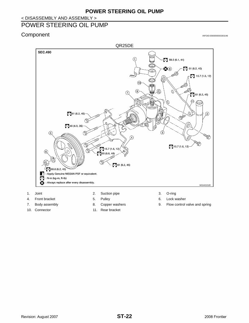
Component INFOID:0000000003303146
QR25DE
WGIA0152E
1. Joint 2. Suction pipe 3. O-ring
4. Front bracket 5. Pulley 6. Lock washer
7. Body assembly 8. Copper washers 9. Flow control valve and spring
10. Connector 11. Rear bracket
ST-22

POWER STEERING OIL PUMP
C
D
E
F
H
I
J
K
L
M
A
B
T
N
O
P
< DISASSEMBLY AND ASSEMBLY >
S
VQ40DE
LGIA0036E
1. Joint 2. Suction pipe 3. O-ring
4. Front bracket 5. Pulley 6. Lock washer
7. Body assembly 8. Copper washers
ST-23
POWER STEERING OIL PUMP
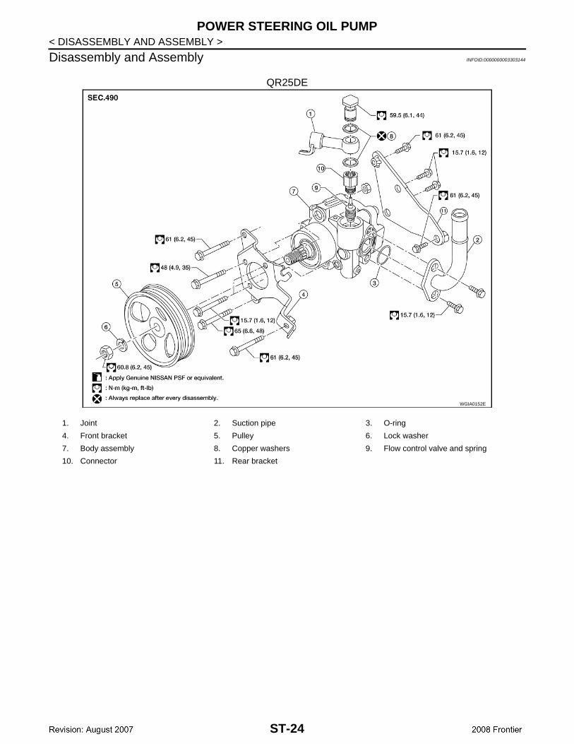
< DISASSEMBLY AND ASSEMBLY >Disassembly and Assembly INFOID:0000000003303144
QR25DE
WGIA0152E
1. Joint 2. Suction pipe 3. O-ring
4. Front bracket 5. Pulley 6. Lock washer
7. Body assembly 8. Copper washers 9. Flow control valve and spring
10. Connector 11. Rear bracket
ST-24

POWER STEERING OIL PUMP
C
D
E
F
H
I
J
K
L
M
A
B
T
N
O
P
< DISASSEMBLY AND ASSEMBLY >
S
VQ40DE
INSPECTION BEFORE DISASSEMBLYDisassemble the power steering oil pump only if the following items are found.• Deformed or damaged pulley, bracket, connector or suction pipe• Oil leakage from the suction pipe or connector.
DISASSEMBLYNOTE:Mount the power steering oil pump in a vise as needed.1. Remove the joint bolt, joint and copper washers.
CAUTION:Do not reuse the copper washers.
2. On QR25DE model, remove connector and flow control valve with spring.3. Remove the suction pipe and O-ring.
CAUTION:Do not reuse the O-ring.
4. Remove the pulley nut and pulley.5. Remove the bracket bolts and bracket(s).
INSPECTION AFTER DISASSEMBLY
Body Assembly InspectionCheck the power steering oil pump body assembly for damage. If any damage is found, replace with a newpower steering oil pump assembly.
ASSEMBLYAssembly is in the reverse order of disassembly.CAUTION:• Do not reuse the copper gaskets• Do not reuse the O-ring. Apply a coat of Genuine NISSAN PSF or equivalent to the O-ring.
LGIA0036E
1. Joint 2. Suction pipe 3. O-ring
4. Front bracket 5. Pulley 6. Lock washer
7. Body assembly 8. Copper washers
ST-25
STEERING GEAR AND LINKAGE
< DISASSEMBLY AND ASSEMBLY >STEERING GEAR AND LINKAGE
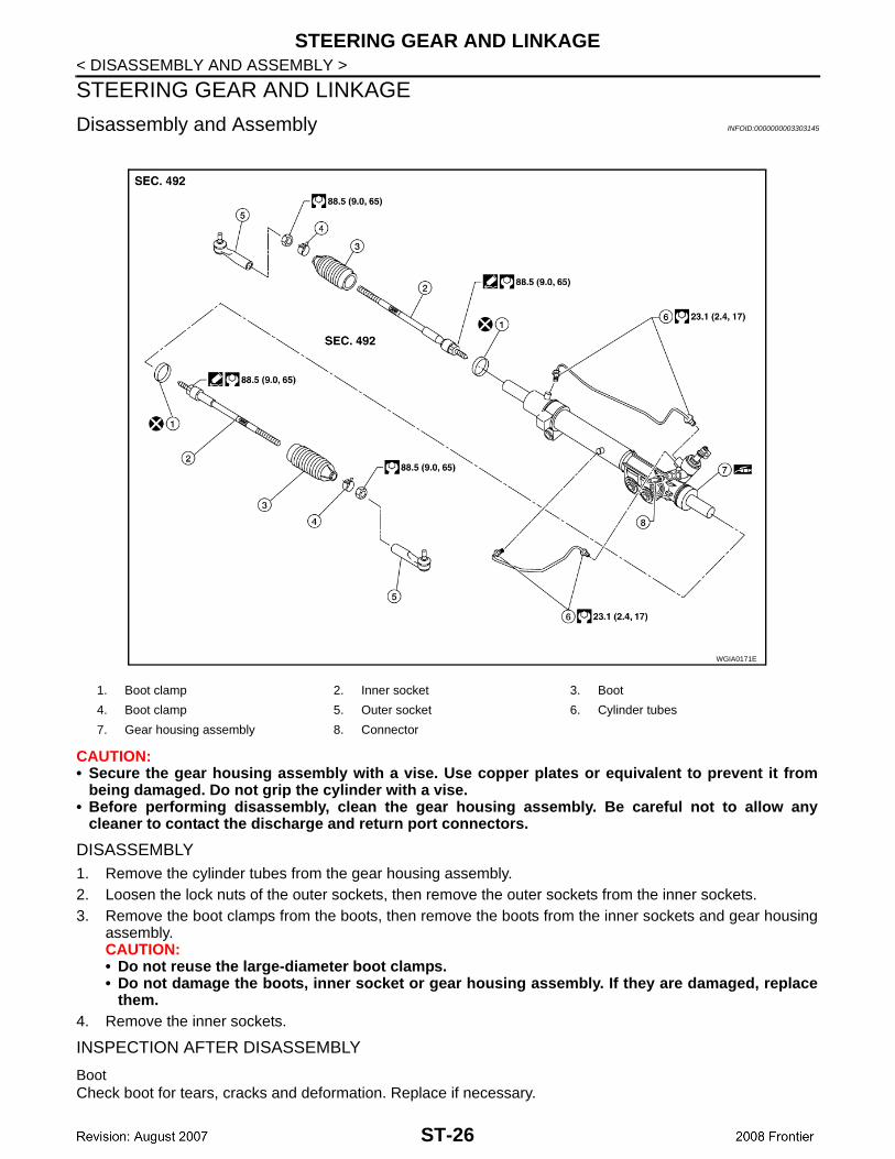
Disassembly and Assembly INFOID:0000000003303145
CAUTION:• Secure the gear housing assembly with a vise. Use copper plates or equivalent to prevent it from
being damaged. Do not grip the cylinder with a vise.• Before performing disassembly, clean the gear housing assembly. Be careful not to allow any
cleaner to contact the discharge and return port connectors.
DISASSEMBLY1. Remove the cylinder tubes from the gear housing assembly.2. Loosen the lock nuts of the outer sockets, then remove the outer sockets from the inner sockets.3. Remove the boot clamps from the boots, then remove the boots from the inner sockets and gear housing
assembly.CAUTION:• Do not reuse the large-diameter boot clamps.• Do not damage the boots, inner socket or gear housing assembly. If they are damaged, replace
them.4. Remove the inner sockets.
INSPECTION AFTER DISASSEMBLY
BootCheck boot for tears, cracks and deformation. Replace if necessary.
1. Boot clamp 2. Inner socket 3. Boot
4. Boot clamp 5. Outer socket 6. Cylinder tubes
7. Gear housing assembly 8. Connector
WGIA0171E
ST-26

STEERING GEAR AND LINKAGE
C
D
E
F
H
I
J
K
L
M
A
B
T
N
O
P
< DISASSEMBLY AND ASSEMBLY >
S
Gear Housing AssemblyCheck gear housing assembly for dents, cracks or damage. Replace as an assembly if necessary.
Outer Socket and Inner Socket
SWING TORQUE• Measure the swing torque, using Tool. When ball stud and inner
socket start moving the measured value must be within the specifi-cation. If the reading is outside the specification, replace thesocket.
ROTATING TORQUE• Measure the rotating torque, using Tool. If the value is outside the
specification, replace the outer sockets.
AXIAL END PLAY• Apply a load of 490 N (50 kg-f, 110 lb-f) to the ball stud axially. Use
a dial gauge to measure the amount of the movement that the studmakes. If the value is outside the specification, replace the sock-ets.
ASSEMBLY1. Install the inner sockets.
Tool number : — (J-44372)
WGIA0131E
Item Outer socket Inner socket
Measuring point Cotter pin hole of stud Shown as L: 83.2 mm (3.276 in)
Swing torque 0.3 − 2.9 N·m (0.03 − 0.29 kg-m, 3 − 25 in-lb) 1.0 − 7.8 N·m (0.11 − 0.79 kg-m, 9 − 69 in-lb)
Measuring value 4.84 − 46.7 N (0.50 − 4.7 kg-f, 4 − 34 lb-f) 12.1 − 93.7 N (1.3 − 9.5 kg-f, 9 − 69 lb-f)
Tool number : ST3127S000 (J-25765-A)
Outer socket rotating torque
: 0.3 − 2.9 N·m (0.03 − 0.29 kg-m, 3 − 25 in-lb)
WGIA0132E
Outer socket : 0.5 mm (0.020 in) or lessInner socket : 0.2 mm (0.08 in) or less
SGIA0057E
ST-27

STEERING GEAR AND LINKAGE
< DISASSEMBLY AND ASSEMBLY >2. Install the large-diameter side of the boots to the gear housingassembly.3. Install the small-diameter side of the boots to the groove of the
inner sockets.
4. Install the boot clamps to the boots, as shown.CAUTION:Do not reuse the large boot clamps.
5. Crimp the large boot clamps, using Tool.
6. Install the cylinder tubes to the gear housing assembly.7. Install the lock nuts and outer sockets to the inner sockets.
8. Thread the outer sockets onto the inner sockets to the specifiedlength "L", then tighten the lock nuts to the specified torque.Refer to "Disassembly and Assembly". Reconfirm that the tie-rod length "L" is within specification.
SGIA0550E
AST139
Tool number : KV40107300 ( — )
RAC1133D
Maximum inner socket length "L"
: 84.0 mm (3.31 in)
SGIA0167E
ST-28
SERVICE DATA AND SPECIFICATIONS (SDS)
C
D
E
F
H
I
J
K
L
M
A
B
T
N
O
P
< SERVICE DATA AND SPECIFICATIONS (SDS)
S
SERVICE DATA AND SPECIFICATIONS (SDS)SERVICE DATA AND SPECIFICATIONS (SDS)
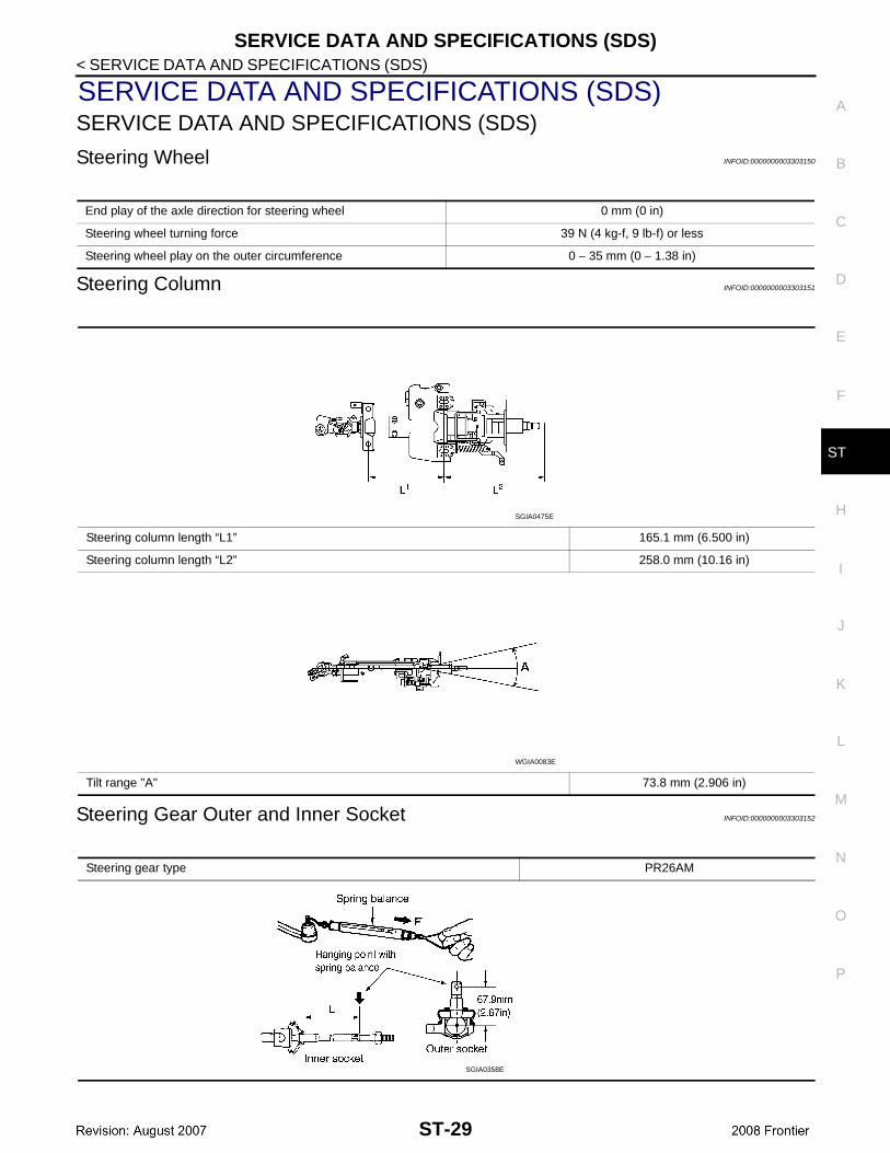
Steering Wheel INFOID:0000000003303150
Steering Column INFOID:0000000003303151
Steering Gear Outer and Inner Socket INFOID:0000000003303152
End play of the axle direction for steering wheel 0 mm (0 in)
Steering wheel turning force 39 N (4 kg-f, 9 lb-f) or less
Steering wheel play on the outer circumference 0 − 35 mm (0 − 1.38 in)
Steering column length “L1” 165.1 mm (6.500 in)
Steering column length “L2” 258.0 mm (10.16 in)
Tilt range "A" 73.8 mm (2.906 in)
SGIA0475E
WGIA0083E
Steering gear type PR26AM
SGIA0358E
ST-29

SERVICE DATA AND SPECIFICATIONS (SDS)
< SERVICE DATA AND SPECIFICATIONS (SDS)Tie-rod INFOID:0000000003303153
Oil Pump INFOID:0000000003303154
Steering Fluid INFOID:0000000003303155
Outer socket
Swinging torque 0.3 − 2.9 N·m (0.03 − 0.29 kg-m, 3 − 25 in-lb)
Measurement on spring balance• Measuring point: cotter pin hole of stud
4.84 − 46.7 N (0.50 − 4.7 kg-f, 4 − 34 lb-f)
Rotating torque 0.3 − 2.9 N·m (0.03 − 0.29 kg-m, 3 − 25 in-lb)
Axial end play 0.5 mm (0.020 in) or less
Inner socket
Swinging torque 1.0 − 7.8 N·m (0.11 − 0.79 kg-m, 9 − 69 in-lb)
Measurement on spring balance• Measuring point: L mark see above,
L=83.2 mm (3.276 in).12.1 − 93.7 N (1.3 − 9.5 kg-f, 9 − 69 lb-f)
Axial end play 0.2 mm (0.08 in) or less
Steering gear type PR26AM
Tie-rod maximum length “L” 84 mm (3.31 in)
SGIA0167E
Oil pump relief hydraulic pressure 8.0 − 8.8 mPa (81.60 − 89.76 kg/cm2, 1160 − 1276 psi)
Fluid capacity Approx. 1.0 (2 1/8 US pt, 1 3/4 Imp pt)
ST-30