Embed Size (px)
Citation preview

Steiner
Utilimax 428Parts List & Mounting Instructions
Jodale • Perry
Printed: 2004/07
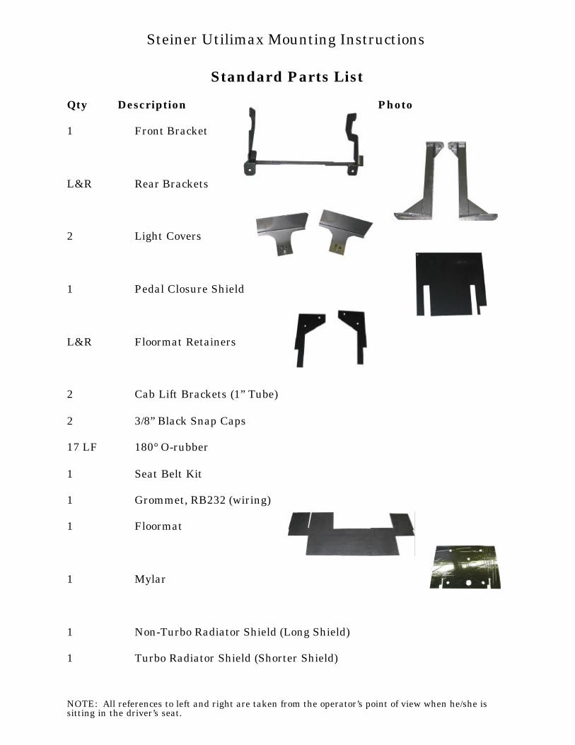
Standard Parts List
Qty Description Photo
1 Front Bracket
L&R Rear Brackets
2 Light Covers
1 Pedal Closure Shield
L&R Floormat Retainers
2 Cab Lift Brackets (1” Tube)
2 3/8” Black Snap Caps
17 LF 180° O-rubber
1 Seat Belt Kit
1 Grommet, RB232 (wiring)
1 Floormat
1 Mylar
1 Non-Turbo Radiator Shield (Long Shield)
1 Turbo Radiator Shield (Shorter Shield)
NOTE: All references to left and right are taken from the operator’s point of view when he/she issitting in the driver’s seat.
Steiner Utilimax Mounting Instructions
Standard Bolts List
Qty Description
4 Isolator, Rubber, 5/8”x2”
4 Bolt, Hex, 5/8” x 3”, Gr. 8, Yellow Dichrome
4 Nut, Hex, Nylon Locking, 5/8”, Gr. 8, Yellow Dichrome
4 Washer, Flat, Rubber, 9/16” x 3”
4 Washer, Flat, Steel, 5/8” x 2”, Yellow Dichrome
12 Bolt, Hex, 7/16” x 1 ½”, Gr. 8, Yellow Dichrome
12 Nut, Hex, Nylon Locking, 7/16”, Gr. 8, Yellow Dichrome
2 Bolt, Hex, ½” x 1 ½”, Gr. 8, Yellow Dichrome
2 Nut, Hex, Nylon Locking, ½”, Gr. 8, Yellow Dichrome
2 Bolt, Flange, ¼” x ½”, Yellow Dichrome
8 Bolt, Flange, ¼” x ¾”, Macro-black
8 Nut, Flange, ¼”, Yellow Dichrome
NOTE: All references to left and right are taken from the operator’s point of view when he/she issitting in the driver’s seat.
Steiner Utilimax Mounting Instructions
Optional Parts ListsHeater Option (if equipped)
Qty Description Photo
LF Hose, Heater, 3/8”
2 Fitting, 1/4NPTx3/8”barb, 180D
2 Clamp, HS-6
2 Grommet, 315-315 (Heater Hose)
Washer Option (if equipped)
Qty Description Photo
1 Tank, Washer
4 Bolt, Flange, ¼” x ¾” Yellow Dichrome
4 Nut, Flange, ¼”, Yellow Dichrome
NOTE: All references to left and right are taken from the operator’s point of view when he/she issitting in the driver’s seat.
Steiner Utilimax Mounting Instructions
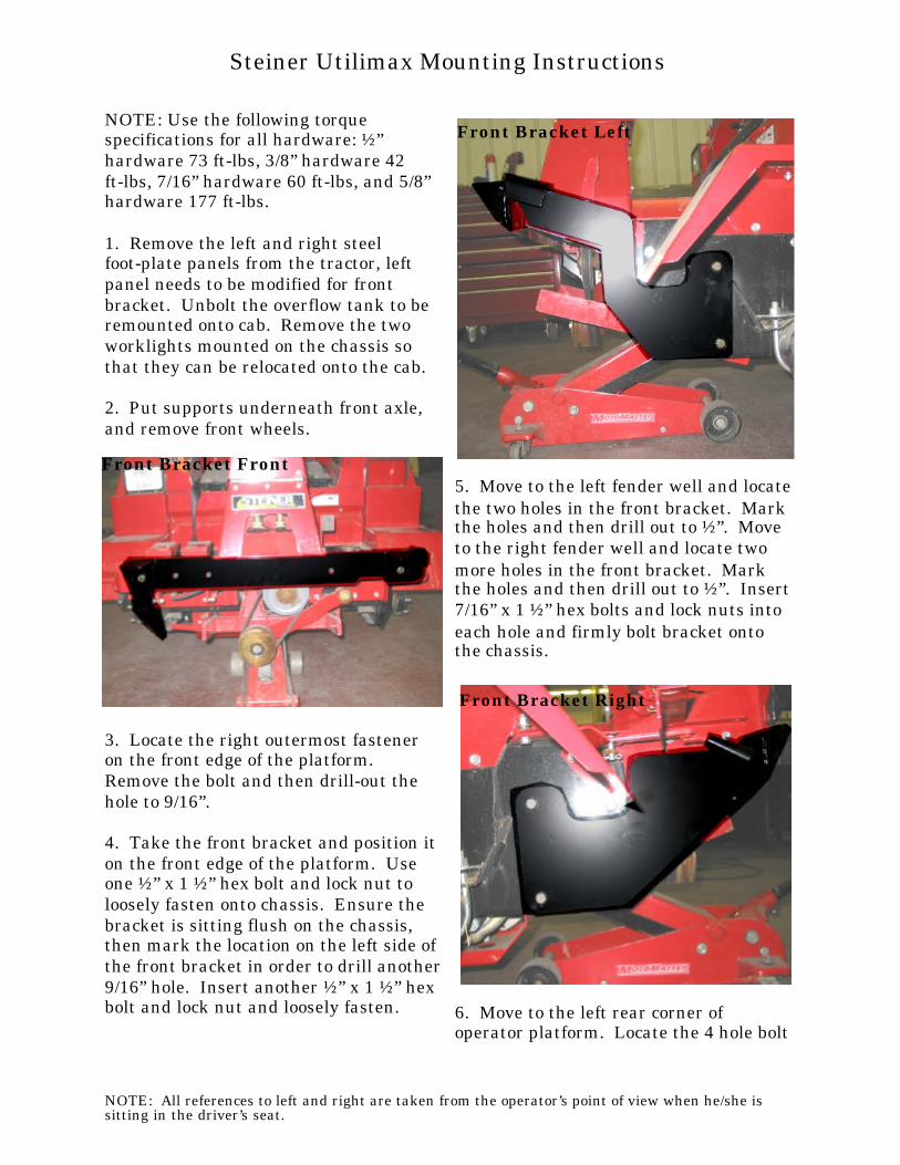
NOTE: Use the following torquespecifications for all hardware: ½”hardware 73 ft-lbs, 3/8” hardware 42ft-lbs, 7/16” hardware 60 ft-lbs, and 5/8”hardware 177 ft-lbs.
1. Remove the left and right steelfoot-plate panels from the tractor, leftpanel needs to be modified for frontbracket. Unbolt the overflow tank to beremounted onto cab. Remove the twoworklights mounted on the chassis sothat they can be relocated onto the cab.
2. Put supports underneath front axle,and remove front wheels.
3. Locate the right outermost fasteneron the front edge of the platform. Remove the bolt and then drill-out thehole to 9/16”.
4. Take the front bracket and position iton the front edge of the platform. Useone ½” x 1 ½” hex bolt and lock nut toloosely fasten onto chassis. Ensure thebracket is sitting flush on the chassis,then mark the location on the left side ofthe front bracket in order to drill another 9/16” hole. Insert another ½” x 1 ½” hexbolt and lock nut and loosely fasten.
5. Move to the left fender well and locate the two holes in the front bracket. Markthe holes and then drill out to ½”. Moveto the right fender well and locate twomore holes in the front bracket. Markthe holes and then drill out to ½”. Insert 7/16” x 1 ½” hex bolts and lock nuts intoeach hole and firmly bolt bracket ontothe chassis.
6. Move to the left rear corner ofoperator platform. Locate the 4 hole bolt
NOTE: All references to left and right are taken from the operator’s point of view when he/she issitting in the driver’s seat.
Steiner Utilimax Mounting Instructions
Front Bracket Front
Front Bracket Left
Front Bracket Right

pattern in the chassis. Remove the boltsand drill out holes to ½”.
7. Move to the right rear corner ofoperator platform. Locate the 4 hole bolt pattern in the chassis. Remove the boltsand drill out holes to ½”.
8. Locate the left rear bracket, and seatbelt kit. Use the holes drilled-out fromStep 6. Use the inside right rear hole onthe rear bracket to mount the seat beltkit. Use the 7/16” x 1 ½” hex bolts andlock nuts to loosely fasten the left rearbracket into place. See Figure.
9. Locate the right rear bracket, andseat belt kit. Use the holes drilled-outfrom Step 7. Use the inside left rear hole on the rear bracket to mount the seatbelt kit. Use the 7/16” x 1 ½” hex boltsand lock nuts to loosely fasten the rightrear bracket into place. See Figure.
10. Locate the two light cover panels. Position one cover inside the left lightopening. Use a ¼” x ½” flange bolt andfasten the cover to the chassis. SeeFigure x. Install the light cover into the
right light opening with the other flangebolt provided.
11. Tilt seat plate forward. Remove therubber seal strips on the seat plate. Take the mylar and position against underside of seat plate. Ensure that there is a good surface for adhesion, clean if necessary. Peal back the backing and then glue intoplace. See Figure.
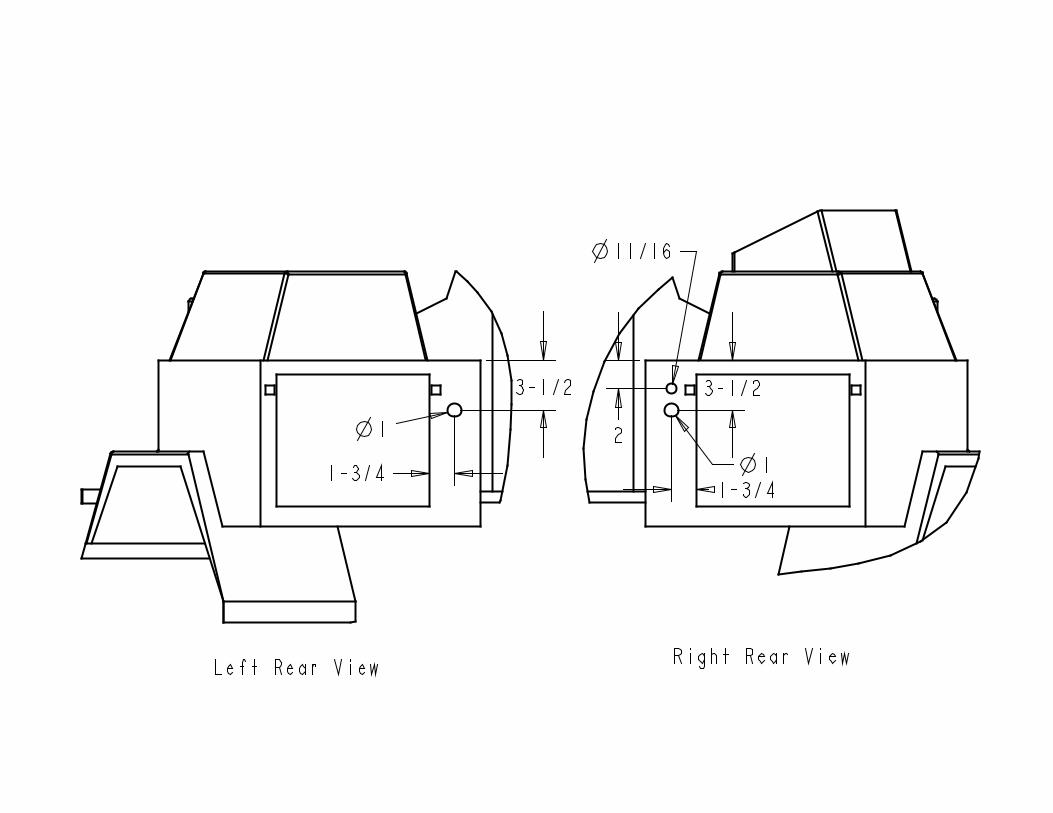
12. Use the provided schematic as aguide and drill the three holes shown forthe heater hoses and the electricalharnesses.
NOTE: All references to left and right are taken from the operator’s point of view when he/she issitting in the driver’s seat.
Steiner Utilimax Mounting Instructions
LH Rear Bracket
RH Rear Bracket
Light Cover

13. Insert the two 315-315 grommetsinto the 1” holes drilled in step 12. Insert the RB232 grommet into the other hole.
If cab is equipped with optional heater,proceed with steps 14-17.
14. Drain engine antifreeze.
15. SUCTION FITTING: Locate theradiator return housing. Remove the
housing completely in order to makedrill/tapping easier. Locate the boss and drill and tap 1/4NPT. Blow out allshavings and then re-install. SeeFigure.
16. PRESSURE FITTING: Locate thethermostat/water pump housing. It isnecessary to drill and tap 1/4NPT thread into the block. Remove the top portionand stuff the thermostat housing andthermostat. Stuff the lower portion with rags to prevent shavings from entering. Ensure the rags go below the boss on the side of the housing. Drill and tap1/4NPT into the housing. See Figure. Carefully blow all shavings fromhousing and then remove rags. If youare not sure if all shavings have beenremoved, install the rad cap and tighten,and then blow air through the suctionfitting hole and blow out shavings andwater from below. See Figure. Re-install the thermostat and then thetop portion of the thermostat housing.
17. Take the 1/4NPTx3/8 barb fittingsand install them into the tapped holesfrom steps 15 & 16. USE a watersealant on the threads!
NOTE: All references to left and right are taken from the operator’s point of view when he/she issitting in the driver’s seat.
Steiner Utilimax Mounting Instructions
Mylar Installed
Suction Fitting
Pressure Fitting

18. Remove both cab doors and the frontplastic fascia panel on the cab. Take thecab lift brackets and install through thehole in the upper A-C crossmember. Attach a lifting strap to the brackets and remove the cab from the shippingbrackets.
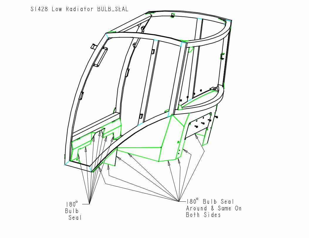
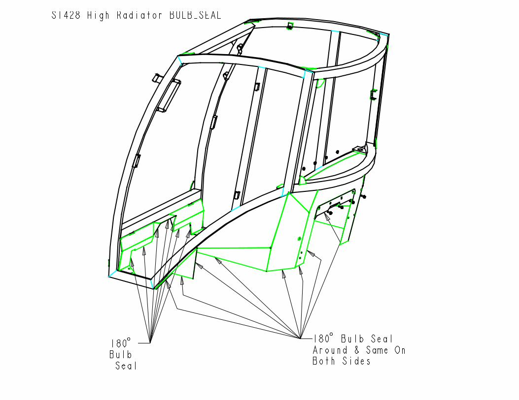
19. Use the provided schematic andinstall the cab weatherstripping asshown. At this point, the radiator shieldmust be installed in the rear panel of the cab. Choose the one necessary, and boltinto place with the ¼” x ¾” flange boltsand nuts.
20. NOW YOU ARE READY TOMOUNT THE CAB. Place one rubberisolator onto each bracket mounting pad. Lift the cab over the machine. Slowlylower the cab down onto the machine. Be careful with the plastic cab sidepanels when lowering so that they do not hit the vehicle panels.
21. Once the cab is down onto the rubber isolators, ensure that the isolatorprotrusion sticks into the mount on thecab. Then use one 5/8” x 3” hex bolt,large steel flat washer, rubber washer,and 5/8” lock nut for each isolator
location in that order. Ensure all boltshave been started. Tighten until there is a 7/8” gap between the steel plates. DONOT OVER-TIGHTEN!
22. Torque all mounting hardware to the specs provided. Remove lift brackets and install the two 3/8” snap caps into theholes. Re-install front fascia panel.
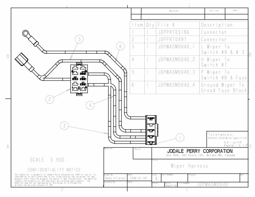
23. Locate the electrical wires at theback of the cab. Route throught the holedrilled earlier in step 12.
24. Connect the heavy red wire to 12Vconstant power on the alternator. Connect the heavy black wire to a tractor ground or chassis screw. Connect theorange wire to the switched red-stripedwire that is on the alternator.
If cab is equipped with optional heater,proceed with steps 25-31.
25. Locate the heater hoses at the backof the cab. Cut the hoses exactly in halfand then route through the holes drilledin Step 12. It doesn’t matter which hosegoes in which hole.
26. Run the hose labelled PRESSURE to the pressure fitting as located by Step16. Attach the hose to the fitting withone HS-6 hose clamp. Ensure that thehose does not contact any moving engineparts.
27. Take the other hose and run to theSUCTION fitting as located by Step 15. Attach the hose to the fitting with oneHS-6 hose clamp. Ensure that the hosedoes not contact any moving engineparts.
28. Ensure that all hose connections aretight, and then refill engine antifreeze.
NOTE: All references to left and right are taken from the operator’s point of view when he/she issitting in the driver’s seat.
Steiner Utilimax Mounting Instructions
Bolt Order

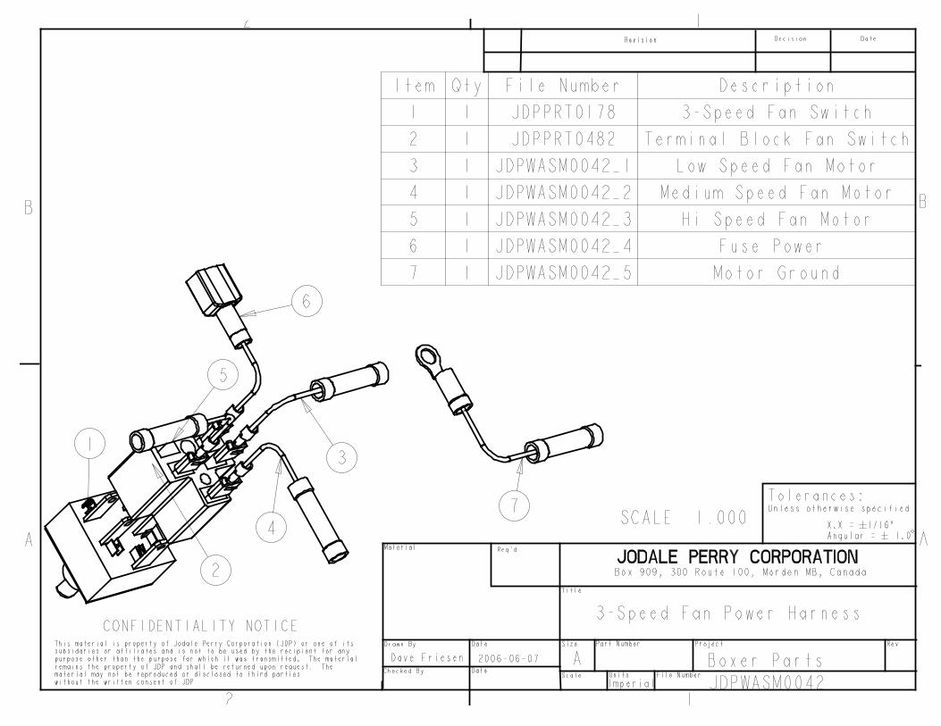
29. Turn the heater control switch in the cab to full open switch and turn fan on.
30. Open radiator cap and then runengine at high idle. Use a funnel in theradiator cap and fill with antifreeze andrun engine so that thermostat opensmany times and funnel is emptied manytimes. This will purge all the air fromthe system.
31. Continue doing step 30 until engineproduces HOT air.
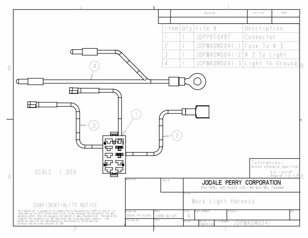
32. Un-bolt the cab roof and remove twosnap caps installed at front of roof. Take the lights from the tractor removedearlier and bolt to the front of the roofthrough the holes provided. Connect tothe cab electrical harness provided. Re-install the roof.
33. Re-install the tractor foot platformsexcept for the left one. Use the attachedblueprint and cut the plate as shown toprovide room for front bracket. Installonce done.
34. Take the pedal closure shield andslide underneth the forward/reversepedals. See Figure.
35. Take the cab floormat and positiononto the foot platform. Ensure that itdoesn’t interfere with any moving pedalsand restrict travel, notch if necessary.
36. Take the floormat retainer platesand place the one in the left front corner. Puncture holes through the floormat and bolt into place with the ¼” x ¾” flangebolts and nuts provided. Repeat for theright side.
37. Use a black silicone sealant to sealall cracks and small openings in the cabafter installation is complete. Ensurethat the rear radiator shield is siliconedfrom outside of the cab to prevent waterentry into the cab.
NOTE: All references to left and right are taken from the operator’s point of view when he/she issitting in the driver’s seat.
Steiner Utilimax Mounting Instructions
Pedal Closure Shield
Floormat Installed