Embed Size (px)
Citation preview
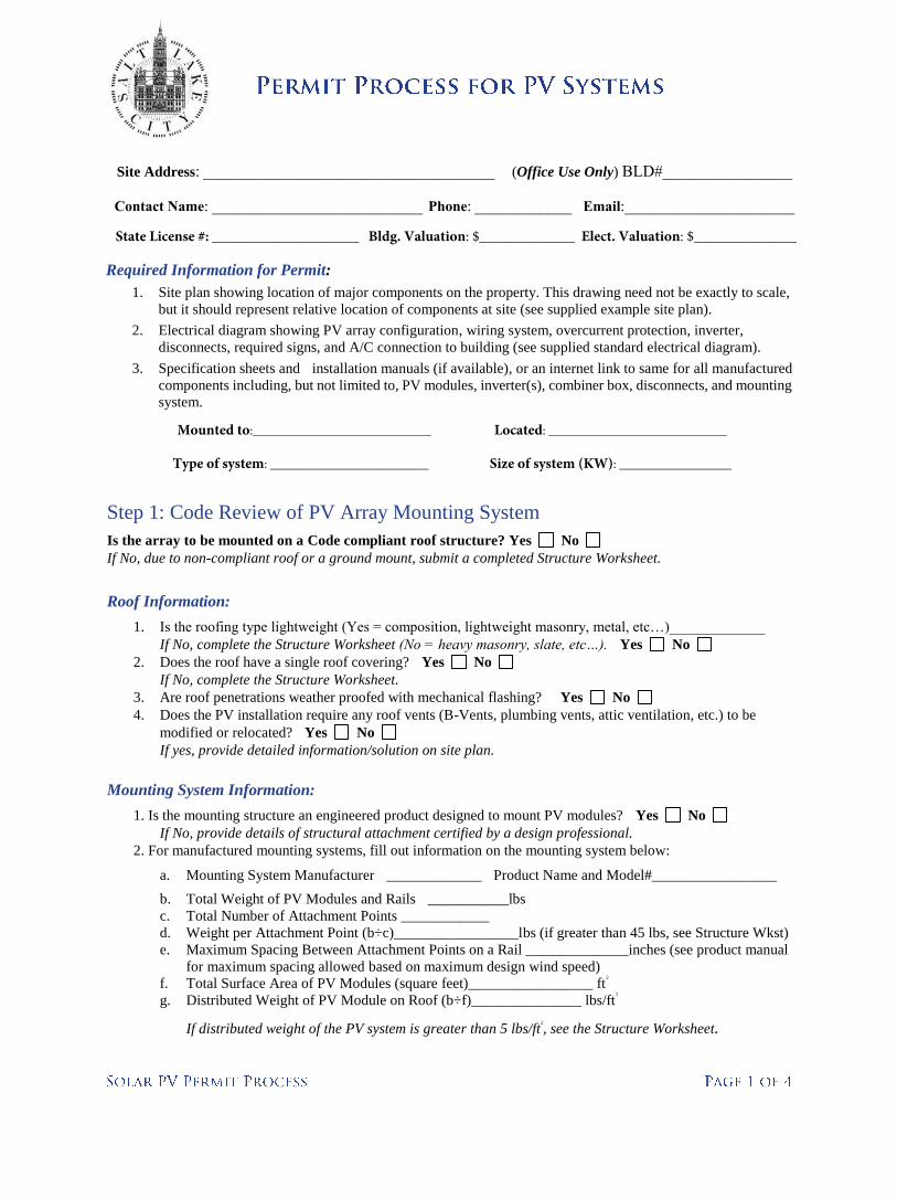
Site Address: ____________________________________ (Office Use Only) BLD#________________
Contact Name: __________________________ Phone: ____________ Email:_____________________
State License #: ____________________ Bldg. Valuation: $_____________ Elect. Valuation: $______________
Required Information for Permit:
1. Site plan showing location of major components on the property. This drawing need not be exactly to scale,
but it should represent relative location of components at site (see supplied example site plan).
2. Electrical diagram showing PV array configuration, wiring system, overcurrent protection, inverter,
disconnects, required signs, and A/C connection to building (see supplied standard electrical diagram).
3. Specification sheets and installation manuals (if available), or an internet link to same for all manufactured
components including, but not limited to, PV modules, inverter(s), combiner box, disconnects, and mounting
system.
Step 1: Code Review of PV Array Mounting System
Is the array to be mounted on a Code compliant roof structure? Yes No
If No, due to non-compliant roof or a ground mount, submit a completed Structure Worksheet.
Roof Information:
1. Is the roofing type lightweight (Yes = composition, lightweight masonry, metal, etc…)_____________
If No, complete the Structure Worksheet (No = heavy masonry, slate, etc…). Yes No
2. Does the roof have a single roof covering? Yes No
If No, complete the Structure Worksheet.
3. Are roof penetrations weather proofed with mechanical flashing? Yes No
4. Does the PV installation require any roof vents (B-Vents, plumbing vents, attic ventilation, etc.) to be
modified or relocated? Yes No
If yes, provide detailed information/solution on site plan.
Mounting System Information:
1. Is the mounting structure an engineered product designed to mount PV modules? Yes No
If No, provide details of structural attachment certified by a design professional.
2. For manufactured mounting systems, fill out information on the mounting system below:
a. Mounting System Manufacturer _____________ Product Name and Model#_________________
b. Total Weight of PV Modules and Rails ___________lbs
c. Total Number of Attachment Points ____________
d. Weight per Attachment Point (b÷c)_________________lbs (if greater than 45 lbs, see Structure Wkst)
e. Maximum Spacing Between Attachment Points on a Rail ______________inches (see product manual
for maximum spacing allowed based on maximum design wind speed)
f. Total Surface Area of PV Modules (square feet)_________________ ft2
g. Distributed Weight of PV Module on Roof (b÷f)_______________ lbs/ft2
If distributed weight of the PV system is greater than 5 lbs/ft2
, see the Structure Worksheet.
Mounted to:___________________________ Located: ___________________________
Type of system: ________________________ Size of system (KW): _________________
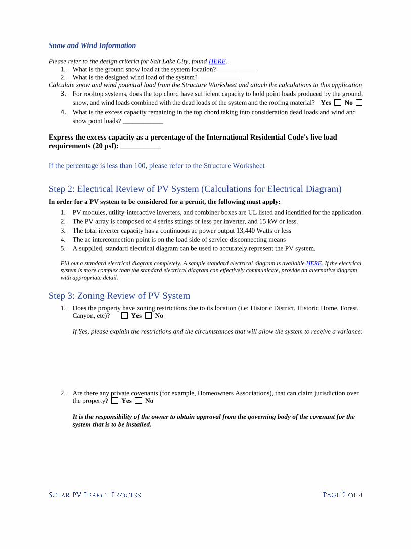
Snow and Wind Information
Please refer to the design criteria for Salt Lake City, found HERE. 1. What is the ground snow load at the system location? ____________
2. What is the designed wind load of the system? ____________
Calculate snow and wind potential load from the Structure Worksheet and attach the calculations to this application 3. For rooftop systems, does the top chord have sufficient capacity to hold point loads produced by the ground,
snow, and wind loads combined with the dead loads of the system and the roofing material? Yes No
4. What is the excess capacity remaining in the top chord taking into consideration dead loads and wind and
snow point loads? ____________
Express the excess capacity as a percentage of the International Residential Code's live load
requirements (20 psf): ____________
If the percentage is less than 100, please refer to the Structure Worksheet
Step 2: Electrical Review of PV System (Calculations for Electrical Diagram)
In order for a PV system to be considered for a permit, the following must apply:
1. PV modules, utility-interactive inverters, and combiner boxes are UL listed and identified for the application.
2. The PV array is composed of 4 series strings or less per inverter, and 15 kW or less.
3. The total inverter capacity has a continuous ac power output 13,440 Watts or less
4. The ac interconnection point is on the load side of service disconnecting means
5. A supplied, standard electrical diagram can be used to accurately represent the PV system.
Fill out a standard electrical diagram completely. A sample standard electrical diagram is available HERE. If the electrical
system is more complex than the standard electrical diagram can effectively communicate, provide an alternative diagram
with appropriate detail.
Step 3: Zoning Review of PV System
1. Does the property have zoning restrictions due to its location (i.e: Historic District, Historic Home, Forest,
Canyon, etc)? Yes No
If Yes, please explain the restrictions and the circumstances that will allow the system to receive a variance:
2. Are there any private covenants (for example, Homeowners Associations), that can claim jurisdiction over
the property? Yes No
It is the responsibility of the owner to obtain approval from the governing body of the covenant for the
system that is to be installed.
Step 4: Fire Review of PV System
In order for a PV system to be considered for a permit, the following must apply:
1. Does the provided Site Plan show a clearly dimensioned pathway and a clearly dimensioned access path to
and around the panels? Fire Code requires a minimum of 3' to ridge and along one side for access.
Yes No
The Fire Code Official must be able to determine that a rational approach has been used and any reductions
in clear area from those required by code are warranted.
2. All System disconnects shall be located in the same location as the utility disconnects.
Agree to provide? Yes No
3. Provide weather resistant, permanently affixed labels to all equipment, conduits, raceways, and junction
boxes. Labels on conduits and raceways shall be affixed every 10 feet.
Agree to provide? Yes No
4. Will there be any conduits under the roof deck or in the attic space? Yes No
If Yes, they must be in metal conduit, clearly labeled, or be MC cable until the first readily accessible
disconnect is reached. Conduit in attic spaces to be installed at least 10" below the roof decking.
Agree to provide? Yes No
5. All metal parts of all modules, modules supports, system equipment, and conductor enclosures shall be
bonded together and connected to the grounding system. The bonding shall also be to the electrical utility.
Agree to provide? Yes No
6. Bipolar source and output circuit equipment shall be marked as follows:
"Warning: Bipolar Photovoltaic Array. Disconnection of neutral or grounded conductors may result
in overvoltage on array inverter"
Agree to provide? Yes No
7. Disconnection of photovoltaic equipment shall be marked as follows:
"Warning: ELECTRIC SHOCK HAZZARD. Do not touch terminals. Terminals on both the line and
load sides may be energized in the open position. "
Agree to provide? Yes No
8. Underground photovoltaic power systems shall be marked as follows:
"Warning: ELECTRIC SHOCK HAZZARD. The DC conductors of this photovoltaic system are
underground and may be energized."
Agree to provide? Yes No
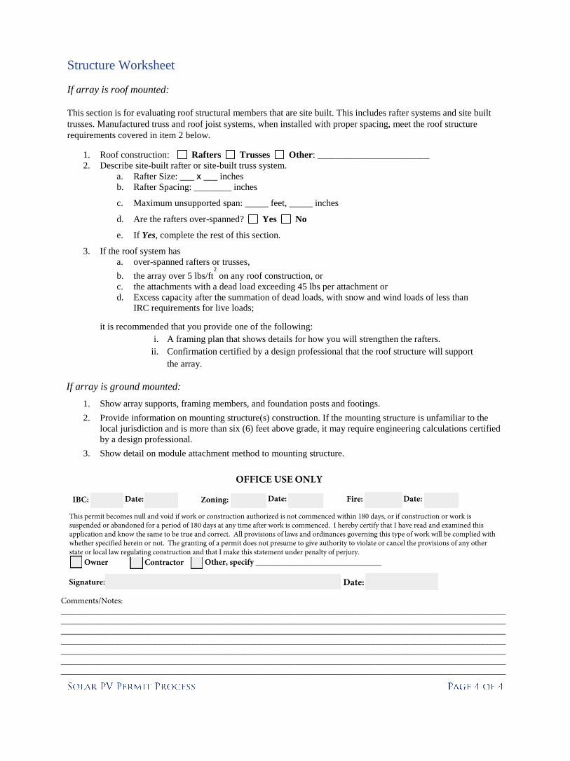
Structure Worksheet
If array is roof mounted:
This section is for evaluating roof structural members that are site built. This includes rafter systems and site built
trusses. Manufactured truss and roof joist systems, when installed with proper spacing, meet the roof structure
requirements covered in item 2 below.
1. Roof construction: Rafters Trusses Other: ________________________
2. Describe site-built rafter or site-built truss system.
a. Rafter Size: ___ x ___ inches
b. Rafter Spacing: ________ inches
c. Maximum unsupported span: _____ feet, _____ inches
d. Are the rafters over-spanned? Yes No
e. If Yes, complete the rest of this section.
3. If the roof system has
a. over-spanned rafters or trusses,
b. the array over 5 lbs/ft2
on any roof construction, or
c. the attachments with a dead load exceeding 45 lbs per attachment or
d. Excess capacity after the summation of dead loads, with snow and wind loads of less than
IRC requirements for live loads;
it is recommended that you provide one of the following:
i. A framing plan that shows details for how you will strengthen the rafters.
ii. Confirmation certified by a design professional that the roof structure will support
the array.
If array is ground mounted:
1. Show array supports, framing members, and foundation posts and footings.
2. Provide information on mounting structure(s) construction. If the mounting structure is unfamiliar to the
local jurisdiction and is more than six (6) feet above grade, it may require engineering calculations certified
by a design professional.
3. Show detail on module attachment method to mounting structure.
OFFICE USE ONLY
IBC: Date: Zoning: Date: Fire: Date:
This permit becomes null and void if work or construction authorized is not commenced within 180 days, or if construction or work is suspended or abandoned for a period of 180 days at any time after work is commenced. I hereby certify that I have read and examined this application and know the same to be true and correct. All provisions of laws and ordinances governing this type of work will be complied with whether specified herein or not. The granting of a permit does not presume to give authority to violate or cancel the provisions of any other state or local law regulating construction and that I make this statement under penalty of perjury.
Owner Contractor Other, specify ______________________________
Signature: Date:
Comments/Notes: ______________________________________________________________________________________________________________________________________________________________________________________________________________________________________________________________________________________________________________________________________________________________________________________________________________________________________________________________________________________________________________________________________________________________________________________________________________________________________________________________________________________________________________________________________________________________________
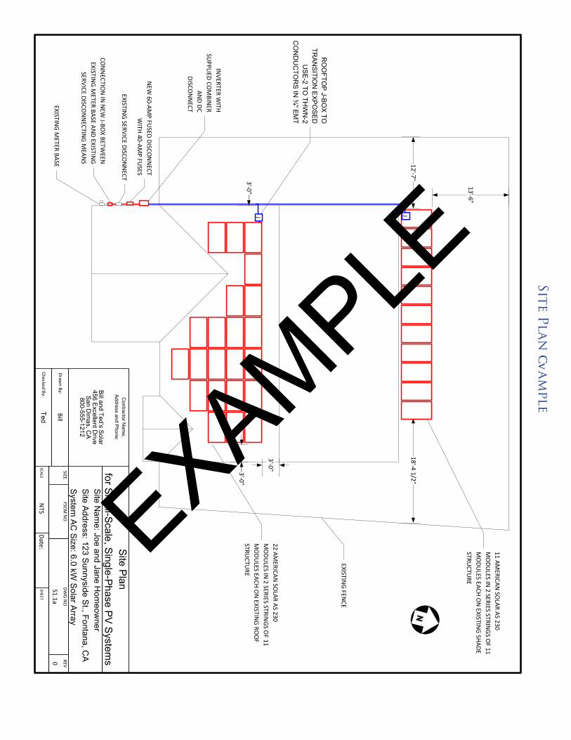
Site Planam
ple
EXAM
PLE
Exped
ited Per
mit Pr
oc
ess for
PV
Systems
5
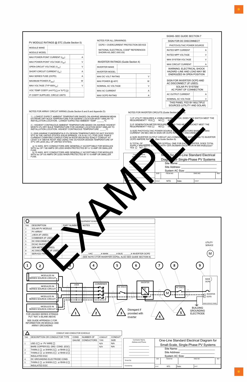
Notes for Standard String System Electrical Diagram
Contractor Name,Address and Phone:
____________________________________________________________________
Notes for One-Line Standard ElectricalDiagram for Single-Phase PV Systems
Site Name: __________________________Site Address: ________________________System AC Size: ______________________
SIZE FSCM NO DWG NO REV
SCALE NTS Date: SHEET
Drawn By:
Checked By:
MAX POWER-POINT CURRENT (IMP)
MAX POWER-POINT VOLTAGE (VMP)
OPEN-CIRCUIT VOLTAGE (VOC)
SHORT-CIRCUIT CURRENT (ISC)
MAX SERIES FUSE (OCPD)
MAXIMUM POWER (PMAX)
MAX VOLTAGE (TYP 600VDC)
VOC TEMP COEFF (mV/oC or %/oC )
IF COEFF SUPPLIED, CIRCLE UNITS
A
V
V
A
A
W
V
MODULE MAKE
MODULE MODEL
PV MODULE RATINGS @ STC (Guide Section 5)
MAX DC VOLT RATING
MAX POWER @ 40oC
NOMINAL AC VOLTAGE
MAX AC CURRENT
MAX OCPD RATING
V
W
V
A
A
INVERTER MAKE
INVERTER MODEL
INVERTER RATINGS (Guide Section 4)
1) IF UTILITY REQUIRES A VISIBLE-BREAK SWITCH, DOES THIS SWITCH MEET THEREQUIREMENT? YES NO N/A
2) IF GENERATION METER REQUIRED, DOES THIS METER SOCKET MEET THEREQUIREMENT? YES NO N/A
3) SIZE PHOTOVOLTAIC POWER SOURCE (DC) CONDUCTORS BASED ON MAXCURRENT ON NEC 690.53 SIGN OR OCPD RATING AT DISCONNECT
4) SIZE INVERTER OUTPUT CIRCUIT (AC) CONDUCTORS ACCORDING TO INVERTEROCPD AMPERE RATING. (See Guide Section 9)
5) TOTAL OF ______ INVERTER OCPD(s), ONE FOR EACH INVERTER. DOES TOTALSUPPLY BREAKERS COMPLY WITH 120% BUSBAR EXCEPTION IN 690.64(B)(2)(a)?YES NO
NOTES FOR INVERTER CIRCUITS (Guide Section 8 and 9):
1.) LOWEST EXPECT AMBIENT TEMPERATURE BASED ON ASHRAE MINIMUM MEANEXTREME DRY BULB TEMPERATURE FOR ASHRAE LOCATION MOST SIMILAR TOINSTALLATION LOCATION. LOWEST EXPECTED AMBIENT TEMP ______oC
2.) HIGHEST CONTINUOUS AMBIENT TEMPERATURE BASED ON ASHRAE HIGHESTMONTH 2% DRY BULB TEMPERATURE FOR ASHRAE LOCATION MOST SIMILAR TOINSTALLATION LOCATION. HIGHEST CONTINUOUS TEMPERATURE _____oC
2.) 2005 ASHRAE FUNDEMENTALS 2% DESIGN TEMPERATURES DO NOT EXCEED47oC IN THE UNITED STATES (PALM SPRINGS, CA IS 44.1oC). FOR LESS THAN 9CURRENT-CARRYING CONDUCTORS IN ROOF-MOUNTED SUNLIT CONDUIT ATLEAST 0.5" ABOVE ROOF AND USING THE OUTDOOR DESIGN TEMPERATURE OF47oC OR LESS (ALL OF UNITED STATES),
a) 12 AWG, 90oC CONDUCTORS ARE GENERALLY ACCEPTABLE FOR MODULESWITH Isc OF 7.68 AMPS OR LESS WHEN PROTECTED BY A 12-AMP OR SMALLERFUSE. b) 10 AWG, 90oC CONDUCTORS ARE GENERALLY ACCEPTABLE FOR MODULESWITH Isc OF 9.6 AMPS OR LESS WHEN PROTECTED BY A 15-AMP OR SMALLERFUSE.
NOTES FOR ARRAY CIRCUIT WIRING (Guide Section 6 and 8 and Appendix D):
OCPD = OVERCURRENT PROTECTION DEVICE
NATIONAL ELECTRICAL CODE® REFERENCESSHOWN AS (NEC XXX.XX)
NOTES FOR ALL DRAWINGS:
SIGNS–SEE GUIDE SECTION 7
SIGN FOR DC DISCONNECT
SIGN FOR INVERTER OCPD ANDAC DISCONNECT (IF USED)
RATED MPP CURRENT
RATED MPP VOLTAGE
MAX SYSTEM VOLTAGE
MAX CIRCUIT CURRENT
A
V
V
A
PHOTOVOLTAIC POWER SOURCE
WARNING: ELECTRICAL SHOCKHAZARD–LINE AND LOAD MAY BEENERGIZED IN OPEN POSITION
AC OUTPUT CURRENT
NOMINAL AC VOLTAGE
A
V
SOLAR PV SYSTEMAC POINT OF CONNECTION
THIS PANEL FED BY MULTIPLESOURCES (UTILITY AND SOLAR)
Exp
edit
ed P
erm
it P
ro
ces
s fo
r P
V S
yste
ms
4
Standard String System Electrical Diagram
EXAM
PLE