Embed Size (px)
Citation preview

IntroductionThe STEVAL-MKI109V3 motherboard provides users with a complete, ready-to-use platform for the evaluation ofSTMicroelectronics MEMS products.
It includes a high-performance 32-bit microcontroller which functions as a bridge between the sensors and a PC, on which youcan download and run the graphical user interface (GUI) or dedicated software routines for customized applications.
The board features a DIL24 socket to mount all available adapters for both digital and analog output MEMS devices.
STEVAL-MKI109V3 Professional MEMS Tool motherboard for MEMS adapter boards
UM2116
User manual
UM2116 - Rev 5 - July 2019For further information contact your local STMicroelectronics sales office.
www.st.com
1 Demonstration kit description
The Professional MEMS Tool is a complete demonstration kit for digital and analog MEMS sensors. Thanks to itsDIL24 connector, a wide range of MEMS adapter boards can be used.
Figure 1. Demonstration board block diagram
The Professional MEMS Tool demonstration kit is based on the STM32F401VE microcontroller and can beconnected to a PC via USB. Data from MEMS sensors connected to the board can be read through the PC GUIprovided with the kit.The Professional MEMS Tool also implements the DFU (device firmware upgrade) feature, so it can bereprogrammed with a new firmware release without the need to use a programmer (see www.st.com/mems).The Professional MEMS Tool integrates:• Six LEDs:
– two LEDs connected via FET buffers to the interrupt pins of digital adapters– a power/USB LED– three general-purpose LEDs for firmware state indication
• Three buttons:– two user buttons on a dedicated GPIO of the microcontroller– a microcontroller reset button
All the MEMS adapter pins are available on board connectors J1 and J3.
UM2116Demonstration kit description
UM2116 - Rev 5 page 2/36
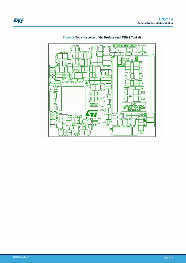
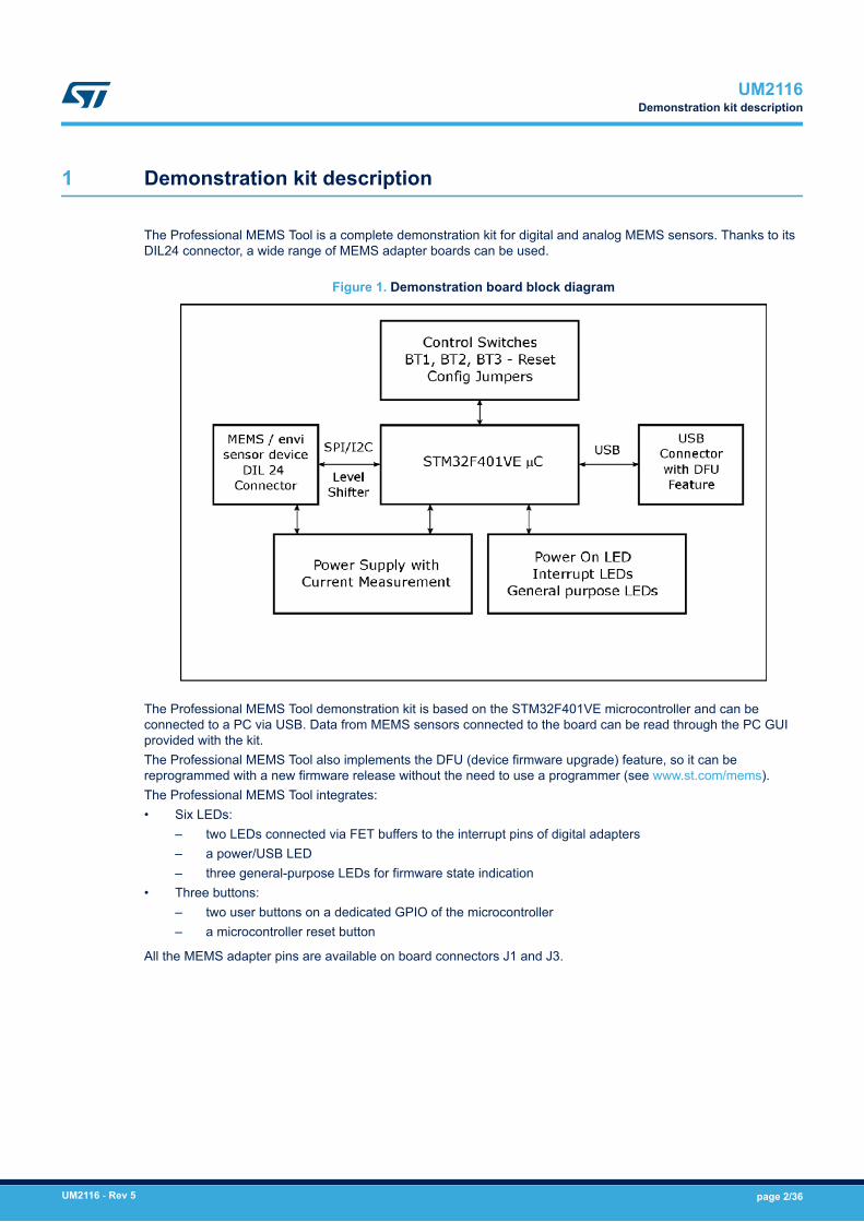
Figure 2. Top silkscreen of the Professional MEMS Tool kit
UM2116Demonstration kit description
UM2116 - Rev 5 page 3/36
Figure 3. Top view of Professional MEMS Tool kit
Figure 3 highlights some of the main components on the top layer of the Professional MEMS Tool kit.1. Button BT3 is used to reset the STM32.2. Button BT2 connected to STM32 GPIOs and available to the user. To enter DFU mode:
a. press buttons BT3 (Reset) and BT2 togetherb. first release BT3 and then release BT2
3. BT1 connected to STM32 GPIOs and available to the user.4. Jumpers J13 (VDD) and J14 (VDDIO) allow the user to measure the sensor current consumption by
connecting a multimeter in series with their terminals.5. Jumper J10 is used as a general purpose input to manually set certain features for several MEMS adapters.6. Jumper J12 is used as a general purpose input to manually set certain features for several MEMS adapters.7. Jumper J11 is used to set the self-test feature during testing of Professional MEMS Tool PCB.8. Jumper J7 is used to select either JTAG (JP7 open – NRST control not allowed from programming
connector J6) or SWD mode (JP7 shorted – NRST control allowed from connector J6).9. J6 connector can be used to reprogram the STM32 and debug the code through the JTAG or SWD
protocols.10. Jumper J4 can be used to directly supply the board (from 4.5 V to 5.5 V) instead of through the USB
connector.11. LED D6 lights up when the board is powered.12. J8 connector can be used for UART RX/TX communication.13. LEDs D1, D2, and D3 are general-purpose LEDs used to indicate firmware states; e.g.:
UM2116Demonstration kit description
UM2116 - Rev 5 page 4/36
a. LED D3 YELOW light up when specific firmware is selected from those availableb. LED D2 RED on indicates that the microcontroller is properly configured for communication with the
sensorc. LED D1 GREEN blinks according to the sensor data rate selected
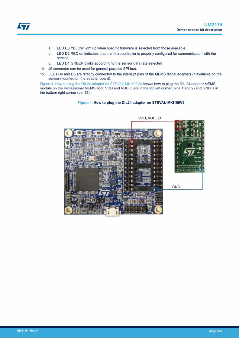
14. J9 connector can be used for general purpose SPI bus.15. LEDs D4 and D5 are directly connected to the interrupt pins of the MEMS digital adapters (if available on the
sensor mounted on the adapter board).Figure 4. How to plug the DIL24 adapter on STEVAL-MKI109V3 shows how to plug the DIL 24 adapter MEMSmodule on the Professional MEMS Tool. VDD and VDDIO are in the top left corner (pins 1 and 2) and GND is inthe bottom right corner (pin 13).
Figure 4. How to plug the DIL24 adapter on STEVAL-MKI109V3
UM2116Demonstration kit description
UM2116 - Rev 5 page 5/36

2 Professional MEMS Tool board installation
The software packages can be downloaded from the st.com website; it is arranged in the following directorystructure:• DRIVER: it contains the installation package for the USB drivers needed to connect the Professional MEMS
Tool board to the PC. No driver is needed on Linux and Mac OS platforms, so this directory is included in theWindows installation package only.
• DFU: it contains the .dfu files and the installation package for the software needed to upgrade the firmwareof the Professional MEMS Tool board.
• FIRMWARE: it contains the source code of the firmware of the Professional MEMS Tool board together withthe corresponding binary file that can be flashed to the board using the DFU software.
2.1 Hardware installation (Windows® platforms)
• For Linux® and Mac OS® platforms, no driver installation is required.• For Windows platforms, install the STM32 virtual COM port driver by running VCP_V1.4.0_Setup.exe in the
DRIVER folder of the Windows installation package and follow the instructions.
Once the driver is installed, connect the demonstration kit board to a free USB port. A confirmation messageshould appear.
Figure 5. Successful device driver installation
Confirm which COM port has been assigned to the board: right click on My Computer and select Manage, thenselect Device Manager and scroll through the list to Ports (COM & LPT).
Note: The STM32 virtual COM port driver for Windows platforms and related documents are packaged with the STSW-STM32102 software download at www.st.com
UM2116Professional MEMS Tool board installation
UM2116 - Rev 5 page 6/36
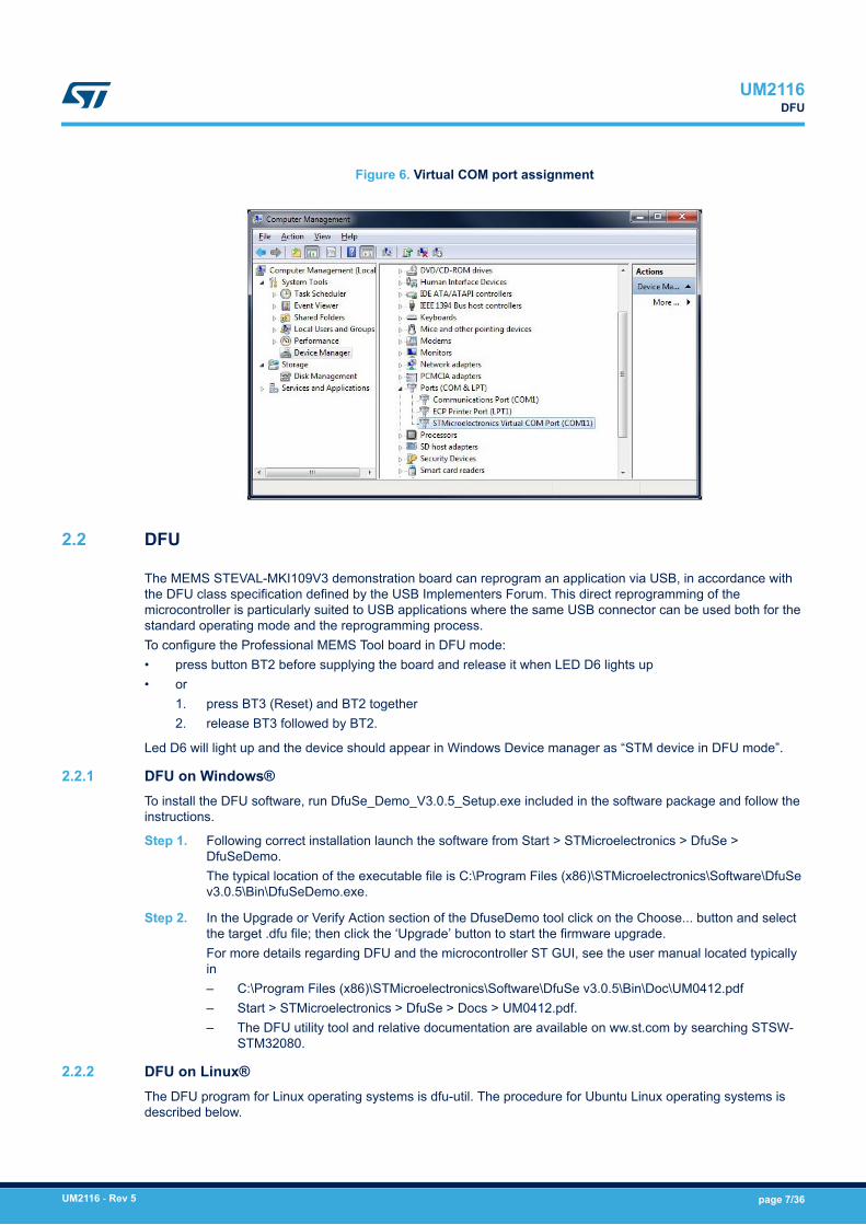
Figure 6. Virtual COM port assignment
2.2 DFU
The MEMS STEVAL-MKI109V3 demonstration board can reprogram an application via USB, in accordance withthe DFU class specification defined by the USB Implementers Forum. This direct reprogramming of themicrocontroller is particularly suited to USB applications where the same USB connector can be used both for thestandard operating mode and the reprogramming process.To configure the Professional MEMS Tool board in DFU mode:• press button BT2 before supplying the board and release it when LED D6 lights up• or
1. press BT3 (Reset) and BT2 together2. release BT3 followed by BT2.
Led D6 will light up and the device should appear in Windows Device manager as “STM device in DFU mode”.
2.2.1 DFU on Windows®To install the DFU software, run DfuSe_Demo_V3.0.5_Setup.exe included in the software package and follow theinstructions.
Step 1. Following correct installation launch the software from Start > STMicroelectronics > DfuSe >DfuSeDemo.The typical location of the executable file is C:\Program Files (x86)\STMicroelectronics\Software\DfuSev3.0.5\Bin\DfuSeDemo.exe.
Step 2. In the Upgrade or Verify Action section of the DfuseDemo tool click on the Choose... button and selectthe target .dfu file; then click the ‘Upgrade’ button to start the firmware upgrade.For more details regarding DFU and the microcontroller ST GUI, see the user manual located typicallyin– C:\Program Files (x86)\STMicroelectronics\Software\DfuSe v3.0.5\Bin\Doc\UM0412.pdf– Start > STMicroelectronics > DfuSe > Docs > UM0412.pdf.– The DFU utility tool and relative documentation are available on ww.st.com by searching STSW-
STM32080.
2.2.2 DFU on Linux®The DFU program for Linux operating systems is dfu-util. The procedure for Ubuntu Linux operating systems isdescribed below.
UM2116DFU
UM2116 - Rev 5 page 7/36

Step 1. Open a terminal and run (with sudo to ensure the correct permissions):sudo apt-get install dfu-util
Step 2. Create a udev rules file:sudo gedit /etc/udev/45-Professional MEMS Tool.rules
Step 3. Fill it with the following content:
# 0483:5740 - STM32F4 in USB Serial Mode (CN5)ATTRS{idVendor}=="0483", ATTRS{idProduct}=="5740",ENV{ID_MM_DEVICE_IGNORE}="1"ATTRS{idVendor}=="0483", ATTRS{idProduct}=="5740",ENV{MTP_NO_PROBE}="1" SUBSYSTEMS=="usb",ATTRS{idVendor}=="0483", ATTRS{idProduct}=="5740",MODE:="0666"KERNEL=="ttyACM*", ATTRS{idVendor}=="0483",ATTRS{idProduct}=="5740", MODE:="0666"# 0483:df11 - STM32F4 in DFU mode (CN5) SUBSYSTEMS=="usb",ATTRS{idVendor}=="0483", ATTRS{idProduct}=="df11", MODE:="0666"
Step 4. Instruct udev to reload its rules:sudo udevadm control --reload-rulesYou should now be able to program the board.
Step 5. Connect the Professional MEMS Tool board in DFU mode and run:sudo dfu-util -a 0 -D dfu_path/file.dfu -d 0483:df11where:– dfu_path is the path to the dfu file– file.dfu is the dfu file name
example: sudo dfu-util -a 0 -D Desktop/Professional MEMS ToolV2_REL_4_0.dfu -d0483:df11.
Step 6. Disconnect and reconnect the board to exit DFU mode and start using the board with the newfirmware.
2.2.3 DFU on Mac OS®The DFU program used for Mac operating systems is dfu-util.
Step 1. Before installing DFU on your Mac OS, you need to install Homebrew. Open a terminal and run:ruby -e "$(curl -fsSL https://raw.github.com/Homebrew/homebrew/go/install)"
Step 2. Install dfu-utils:brew install dfu-utilYou should now be able to program the board
Step 3. Connect the Professional MEMS Tool board in DFU mode, and run:dfu-util -a 0 -D dfu_path/file.dfu -d 0483:df11where:– dfu_path is the path to the dfu file– file.dfu is the dfu file name
example: dfu-util -a 0 -D Desktop/Professional MEMS ToolV2_REL_4_0.dfu -d0483:df11.
Step 4. Disconnect and reconnect the board to exit DFU mode and start using the board with the newfirmware.
UM2116DFU
UM2116 - Rev 5 page 8/36
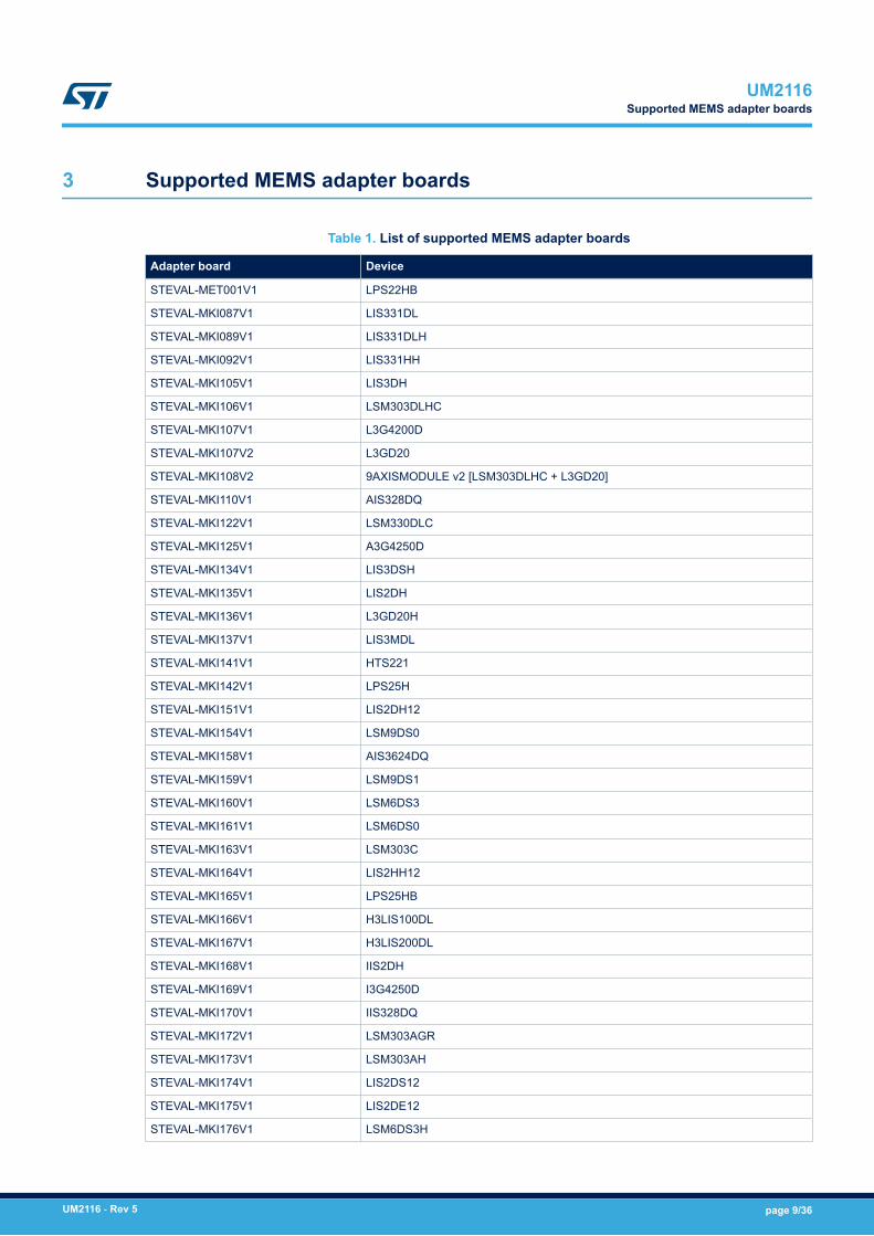
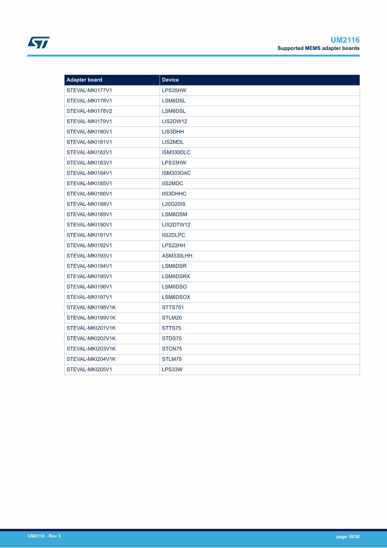
3 Supported MEMS adapter boards
Table 1. List of supported MEMS adapter boards
Adapter board Device
STEVAL-MET001V1 LPS22HB
STEVAL-MKI087V1 LIS331DL
STEVAL-MKI089V1 LIS331DLH
STEVAL-MKI092V1 LIS331HH
STEVAL-MKI105V1 LIS3DH
STEVAL-MKI106V1 LSM303DLHC
STEVAL-MKI107V1 L3G4200D
STEVAL-MKI107V2 L3GD20
STEVAL-MKI108V2 9AXISMODULE v2 [LSM303DLHC + L3GD20]
STEVAL-MKI110V1 AIS328DQ
STEVAL-MKI122V1 LSM330DLC
STEVAL-MKI125V1 A3G4250D
STEVAL-MKI134V1 LIS3DSH
STEVAL-MKI135V1 LIS2DH
STEVAL-MKI136V1 L3GD20H
STEVAL-MKI137V1 LIS3MDL
STEVAL-MKI141V1 HTS221
STEVAL-MKI142V1 LPS25H
STEVAL-MKI151V1 LIS2DH12
STEVAL-MKI154V1 LSM9DS0
STEVAL-MKI158V1 AIS3624DQ
STEVAL-MKI159V1 LSM9DS1
STEVAL-MKI160V1 LSM6DS3
STEVAL-MKI161V1 LSM6DS0
STEVAL-MKI163V1 LSM303C
STEVAL-MKI164V1 LIS2HH12
STEVAL-MKI165V1 LPS25HB
STEVAL-MKI166V1 H3LIS100DL
STEVAL-MKI167V1 H3LIS200DL
STEVAL-MKI168V1 IIS2DH
STEVAL-MKI169V1 I3G4250D
STEVAL-MKI170V1 IIS328DQ
STEVAL-MKI172V1 LSM303AGR
STEVAL-MKI173V1 LSM303AH
STEVAL-MKI174V1 LIS2DS12
STEVAL-MKI175V1 LIS2DE12
STEVAL-MKI176V1 LSM6DS3H
UM2116Supported MEMS adapter boards
UM2116 - Rev 5 page 9/36
Adapter board Device
STEVAL-MKI177V1 LPS35HW
STEVAL-MKI178V1 LSM6DSL
STEVAL-MKI178V2 LSM6DSL
STEVAL-MKI179V1 LIS2DW12
STEVAL-MKI180V1 LIS3DHH
STEVAL-MKI181V1 LIS2MDL
STEVAL-MKI182V1 ISM330DLC
STEVAL-MKI183V1 LPS33HW
STEVAL-MKI184V1 ISM303DAC
STEVAL-MKI185V1 IIS2MDC
STEVAL-MKI186V1 IIS3DHHC
STEVAL-MKI188V1 L20G20IS
STEVAL-MKI189V1 LSM6DSM
STEVAL-MKI190V1 LIS2DTW12
STEVAL-MKI191V1 IIS2DLPC
STEVAL-MKI192V1 LPS22HH
STEVAL-MKI193V1 ASM330LHH
STEVAL-MKI194V1 LSM6DSR
STEVAL-MKI195V1 LSM6DSRX
STEVAL-MKI196V1 LSM6DSO
STEVAL-MKI197V1 LSM6DSOX
STEVAL-MKI198V1K STTS751
STEVAL-MKI199V1K STLM20
STEVAL-MKI201V1K STTS75
STEVAL-MKI202V1K STDS75
STEVAL-MKI203V1K STCN75
STEVAL-MKI204V1K STLM75
STEVAL-MKI205V1 LPS33W
UM2116Supported MEMS adapter boards
UM2116 - Rev 5 page 10/36
4 Supported commands
The microcontroller mounted on the Professional MEMS Tool board is equipped with dedicated firmware thatallows control of the digital output MEMS sensor, and acquisition of the measured data.The firmware also handles the communication between the board and the PC through the USB bus.
4.1 Getting started
Before using the commands supported by the firmware, the following procedure must be performed:
Step 1. Connect the Professional MEMS Tool to the USB port
Step 2. Launch an application that allows sending commands through the virtual serial port. The remainder ofthis document assumes the use of Microsoft® HyperTerminal program available with the Windows XPoperating system, but you can use any similar tool.
Step 3. Create a new connection, enter a name (e.g. STEVAL-MKI109V3), and click OK.
Step 4. In the Connect Using field, select the virtual COM port to which the USB port has been mapped, andclick OK.
Step 5. In port settings, set bits per second to 115200, data bits to 8, parity to none, stop bits to1, and flow control to none; click OK
Step 6. In the HyperTerminal application window, select files > properties > settings, then clickASCII Setup.
Step 7. Select Send line ends with line feeds and Echo typed characters locallyStep 8. Click OK to close the ASCII Setup window
Step 9. Click OK button to close the Properties window.Once this procedure has been completed you can use the commands described in the followingsections by typing them in the “HyperTerminal” window.
4.1.1 Quick startThe basic sequence of commands (based on the LIS3DH accelerometer) to start a data communication sessionand to retrieve X, Y, and Z acceleration data from the demonstration kit is:
Step 1. Connect the Professional MEMS Tool to the USB port
Step 2. Start “Microsoft© HyperTerminal” (or another similar application) and configure it as described inSection 4.1 Getting started
Step 3. Enter the *setdb105v1 command in the HyperTerminal” window, (supposing the LIS3DH adapterboard is used – for other adapters see the relevant datasheets to check the register configuration),enter the command * Zoff to enable the control of the device by the STM32F401VE microcontroller,and *w2047 to switch on the LIS3DH and to set the data rate to 50 Hz
Step 4. Send the *debug command to get the X, Y, and Z data measured by the sensor
Step 5. Send *stop to end the continuous acquisition and visualization.
4.2 Supported commands
The firmware supports a wide range of MEMS adapters; the complete list of supported commands and theirdescriptions are given below. Commands are not case sensitive.
UM2116Supported commands
UM2116 - Rev 5 page 11/36
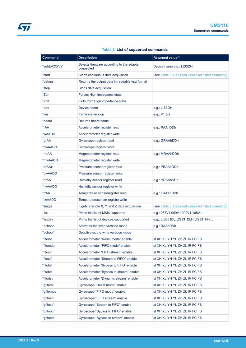
Table 2. List of supported commands
Command Description Returned value(1)
*setdbXXXVY Selects firmware according to the adapterconnected Device name e.g.: LIS3DH
*start Starts continuous data acquisition (see Table 3. Returned values for *start command)
*debug Returns the output data in readable text format
*stop Stops data acquisition
*Zon Forces High impedance state
*Zoff Exits from High impedance state
*dev Device name e.g.: LIS3DH
*ver Firmware version e.g.: V1.5.2
*board Returns board name
*rAA Accelerometer register read e.g.: RAAhDDh
*wAADD Accelerometer register write
*grAA Gyroscope register read e.g.: GRAAhDDh
*gwAADD Gyroscope register write
*mrAA Magnetometer register read e.g.: MRAAhDDh
*mwAADD Magnetometer register write
*prAAx Pressure sensor register read e.g.: PRAAhDDh
*pwAADD Pressure sensor register write
*hrAA Humidity sensor register read e.g.: HRAAhDDh
*hwAADD Humidity sensor register write
*trAA Temperature sensorregister read e.g.: TRAAhDDh
*twAADD Temperaturesensor register write
*single It gets a single X, Y, and Z data acquisition (see Table 3. Returned values for *start command)
*list Prints the list of MKIs supported e.g.: 087V1 089V1 092V1 105V1...
*listdev Prints the list of devices supported e.g.: LIS331DL LIS331DLH LIS331HH…
*echoon Activates the write verbose mode e.g.: RAAhDDh
*echooff Deactivates the write verbose mode
*fiforst Accelerometer “Reset mode” enable st XH XL YH YL ZH ZL IR FC FS
*fifomde Accelerometer “FIFO mode” enable st XH XL YH YL ZH ZL IR FC FS
*fifostr Accelerometer “FIFO stream” enable st XH XL YH YL ZH ZL IR FC FS
*fifostf Accelerometer “Stream to FIFO” enable st XH XL YH YL ZH ZL IR FC FS
*fifobtf Accelerometer “Bypass to FIFO” enable st XH XL YH YL ZH ZL IR FC FS
*fifobts Accelerometer “Bypass to stream” enable st XH XL YH YL ZH ZL IR FC FS
*fifodstr Accelerometer “Dynamic stream” enable st XH XL YH YL ZH ZL IR FC FS
*gfiforst Gyroscope “Reset mode” enable st XH XL YH YL ZH ZL IR FC FS
*gfifomde Gyroscope “FIFO mode” enable st XH XL YH YL ZH ZL IR FC FS
*gfifostr Gyroscope “FIFO stream” enable st XH XL YH YL ZH ZL IR FC FS
*gfifostf Gyroscope “Stream to FIFO” enable st XH XL YH YL ZH ZL IR FC FS
*gfifobtf Gyroscope “Bypass to FIFO” enable st XH XL YH YL ZH ZL IR FC FS
*gfifobts Gyroscope “Bypass to stream” enable st XH XL YH YL ZH ZL IR FC FS
UM2116Supported commands
UM2116 - Rev 5 page 12/36
Command Description Returned value(1)
*gfifodstr Gyroscope “Dynamic stream” enable st XH XL YH YL ZH ZL IR FC FS
*pfiforst Pressure sensor “Reset mode” enable st XH XL YH YL ZH ZL IR FC FS
*pfifomde Pressure sensor “FIFO mode” enable st XH XL YH YL ZH ZL IR FC FS
*pfifostr Pressure sensor “FIFO stream” enable st XH XL YH YL ZH ZL IR FC FS
*pfifostf Pressure sensor “Stream to FIFO” enable st XH XL YH YL ZH ZL IR FC FS
*pfifobtf Pressure sensor “Bypass to FIFO” enable st XH XL YH YL ZH ZL IR FC FS
*pfifobts Pressure sensor “Bypass to stream” enable st XH XL YH YL ZH ZL IR FC FS
*pfifodstr Pressure sensor “Dynamic stream” enable st XH XL YH YL ZH ZL IR FC FS
*POWER_ON Turns on VDD and VDDIO power supply
*POWER_OFF Turns off VDD and VDDIO power supply
*setvddaX.Y Sets VDD voltage value “X.Y” Volts e.g.: 3.6
*setvddioX.Y Sets VDDIO voltage value “X.Y” Volts e.g.: 3.6
*adc_single Measures VDD, VDDIO, IDD, IDDIO and anothervalues sent in binary form adc:D1D2D3…D20
*rmAA1NN Multiple read of NN Accelerometer successiveregisters RMAA1hNNhDD1hDD2...DDNNh
*mutli-rAA1AA2 AA3…Accelerometer registers
multiple readMULTI-RAA1hDD1h AA2hDD2h…. AAnDDnh
*grmAA1NN Multiple read of NN Gyroscope successiveregisters GRMAA1hNNhDD1hDD2...DDNNh
*multi-grAA1AA2AA3…
Gyroscope registers
multiple readMULTI-GRAA1hDD1h AA2hDD2h…. AAnDDnh
*mrmAA1NN Multiple read of NN Magnetometer successiveregisters MRMAA1hNNhDD1hDD2...DDNNh
*multi-mrAA1AA2AA3…
Magnetometer registers
multiple readMULTI-MRAA1hDD1h AA2hDD2h…. AAnDDnh
*prmAA1NN Multiple read of NN Pressure sensor successiveregisters PRMAA1hNNhDD1hDD2...DDNNh
*multi-prAA1AA2AA3…
Pressure sensor registers
multiple readMULTI-PRAA1hDD1h AA2hDD2h…. AAnDDnh
*hrmAA1NN Multiple read of NN Humidity sensor successiveregisters HRMAA1hNNhDD1hDD2...DDNNh
*multi-hrAA1AA2AA3…
Humidity sensor registers
multiple readMULTI-HRAA1hDD1h AA2hDD2h…. AAnDDnh
*trmAA1NN Multiple read of NN Temperature sensorsuccessive registers TRMAA1hNNhDD1hDD2...DDNNh
*multi-trAA1AA2 AA3… Temperature sensor registers multiple read MULTI-TRAA1hDD1h AA2hDD2h…. AAnDDnh
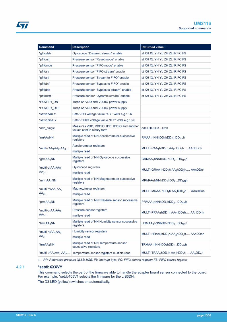
1. RP: Reference pressure XLSB.MSB, IR: interrupt byte; FC: FIFO control register; FS: FIFO source register
4.2.1 *setdbXXXVYThis command selects the part of the firmware able to handle the adapter board sensor connected to the board.For example, *setdb105V1 selects the firmware for the LIS3DH.The D3 LED (yellow) switches on automatically.
UM2116Supported commands
UM2116 - Rev 5 page 13/36
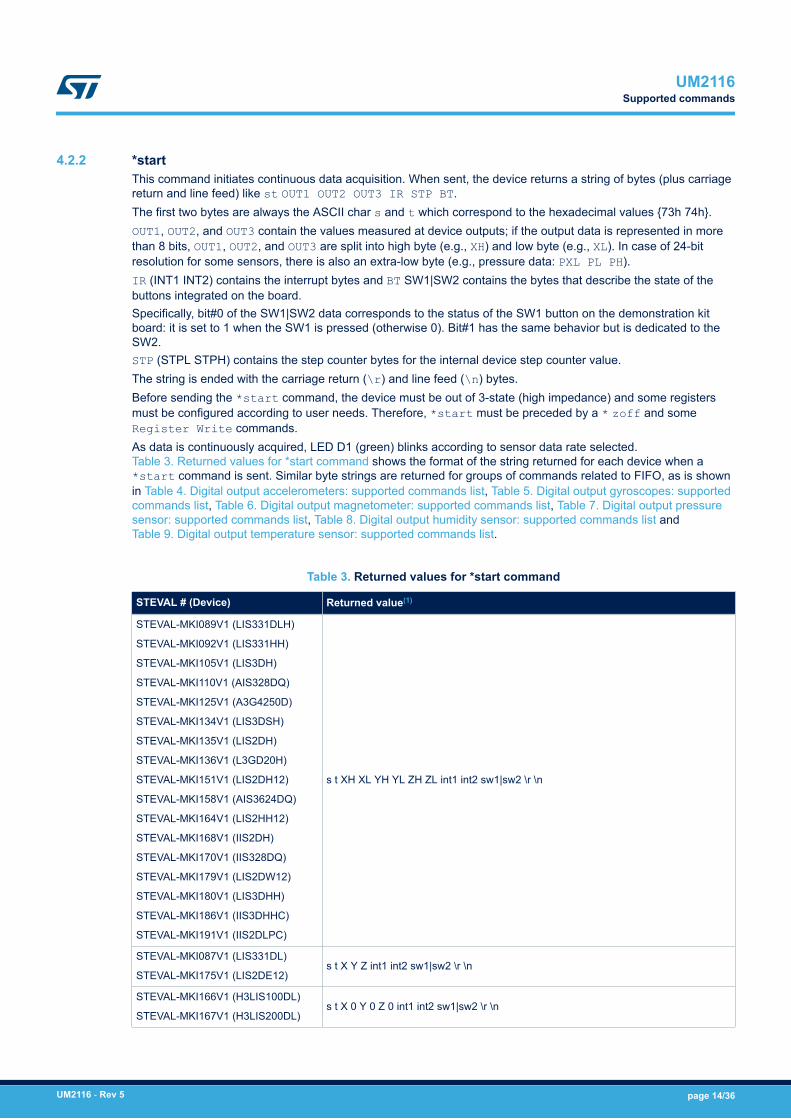
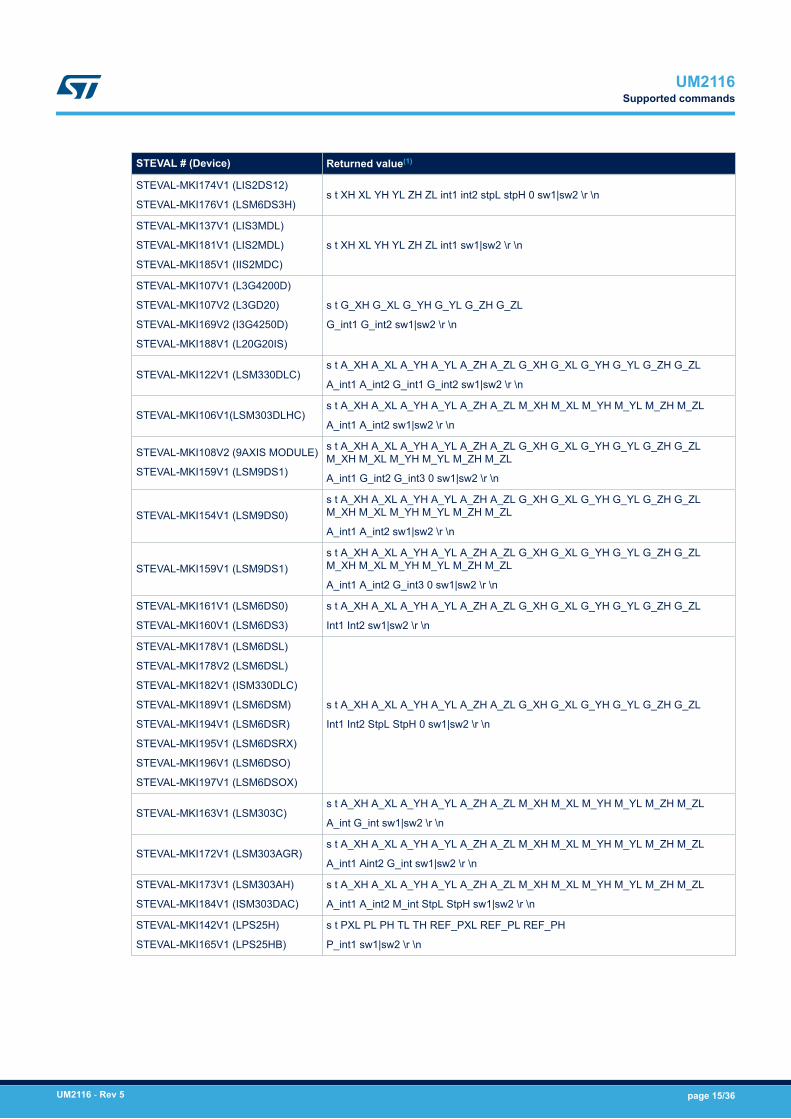
4.2.2 *startThis command initiates continuous data acquisition. When sent, the device returns a string of bytes (plus carriagereturn and line feed) like st OUT1 OUT2 OUT3 IR STP BT.The first two bytes are always the ASCII char s and t which correspond to the hexadecimal values {73h 74h}.OUT1, OUT2, and OUT3 contain the values measured at device outputs; if the output data is represented in morethan 8 bits, OUT1, OUT2, and OUT3 are split into high byte (e.g., XH) and low byte (e.g., XL). In case of 24-bitresolution for some sensors, there is also an extra-low byte (e.g., pressure data: PXL PL PH).IR (INT1 INT2) contains the interrupt bytes and BT SW1|SW2 contains the bytes that describe the state of thebuttons integrated on the board.Specifically, bit#0 of the SW1|SW2 data corresponds to the status of the SW1 button on the demonstration kitboard: it is set to 1 when the SW1 is pressed (otherwise 0). Bit#1 has the same behavior but is dedicated to theSW2.STP (STPL STPH) contains the step counter bytes for the internal device step counter value.The string is ended with the carriage return (\r) and line feed (\n) bytes.Before sending the *start command, the device must be out of 3-state (high impedance) and some registersmust be configured according to user needs. Therefore, *start must be preceded by a * zoff and someRegister Write commands.As data is continuously acquired, LED D1 (green) blinks according to sensor data rate selected.Table 3. Returned values for *start command shows the format of the string returned for each device when a*start command is sent. Similar byte strings are returned for groups of commands related to FIFO, as is shownin Table 4. Digital output accelerometers: supported commands list, Table 5. Digital output gyroscopes: supportedcommands list, Table 6. Digital output magnetometer: supported commands list, Table 7. Digital output pressuresensor: supported commands list, Table 8. Digital output humidity sensor: supported commands list andTable 9. Digital output temperature sensor: supported commands list.
Table 3. Returned values for *start command
STEVAL # (Device) Returned value(1)
STEVAL-MKI089V1 (LIS331DLH)
STEVAL-MKI092V1 (LIS331HH)
STEVAL-MKI105V1 (LIS3DH)
STEVAL-MKI110V1 (AIS328DQ)
STEVAL-MKI125V1 (A3G4250D)
STEVAL-MKI134V1 (LIS3DSH)
STEVAL-MKI135V1 (LIS2DH)
STEVAL-MKI136V1 (L3GD20H)
STEVAL-MKI151V1 (LIS2DH12)
STEVAL-MKI158V1 (AIS3624DQ)
STEVAL-MKI164V1 (LIS2HH12)
STEVAL-MKI168V1 (IIS2DH)
STEVAL-MKI170V1 (IIS328DQ)
STEVAL-MKI179V1 (LIS2DW12)
STEVAL-MKI180V1 (LIS3DHH)
STEVAL-MKI186V1 (IIS3DHHC)
STEVAL-MKI191V1 (IIS2DLPC)
s t XH XL YH YL ZH ZL int1 int2 sw1|sw2 \r \n
STEVAL-MKI087V1 (LIS331DL)
STEVAL-MKI175V1 (LIS2DE12)s t X Y Z int1 int2 sw1|sw2 \r \n
STEVAL-MKI166V1 (H3LIS100DL)
STEVAL-MKI167V1 (H3LIS200DL)s t X 0 Y 0 Z 0 int1 int2 sw1|sw2 \r \n
UM2116Supported commands
UM2116 - Rev 5 page 14/36
STEVAL # (Device) Returned value(1)
STEVAL-MKI174V1 (LIS2DS12)
STEVAL-MKI176V1 (LSM6DS3H)s t XH XL YH YL ZH ZL int1 int2 stpL stpH 0 sw1|sw2 \r \n
STEVAL-MKI137V1 (LIS3MDL)
STEVAL-MKI181V1 (LIS2MDL)
STEVAL-MKI185V1 (IIS2MDC)
s t XH XL YH YL ZH ZL int1 sw1|sw2 \r \n
STEVAL-MKI107V1 (L3G4200D)
STEVAL-MKI107V2 (L3GD20)
STEVAL-MKI169V2 (I3G4250D)
STEVAL-MKI188V1 (L20G20IS)
s t G_XH G_XL G_YH G_YL G_ZH G_ZL
G_int1 G_int2 sw1|sw2 \r \n
STEVAL-MKI122V1 (LSM330DLC)s t A_XH A_XL A_YH A_YL A_ZH A_ZL G_XH G_XL G_YH G_YL G_ZH G_ZL
A_int1 A_int2 G_int1 G_int2 sw1|sw2 \r \n
STEVAL-MKI106V1(LSM303DLHC)s t A_XH A_XL A_YH A_YL A_ZH A_ZL M_XH M_XL M_YH M_YL M_ZH M_ZL
A_int1 A_int2 sw1|sw2 \r \n
STEVAL-MKI108V2 (9AXIS MODULE)
STEVAL-MKI159V1 (LSM9DS1)
s t A_XH A_XL A_YH A_YL A_ZH A_ZL G_XH G_XL G_YH G_YL G_ZH G_ZLM_XH M_XL M_YH M_YL M_ZH M_ZL
A_int1 G_int2 G_int3 0 sw1|sw2 \r \n
STEVAL-MKI154V1 (LSM9DS0)s t A_XH A_XL A_YH A_YL A_ZH A_ZL G_XH G_XL G_YH G_YL G_ZH G_ZLM_XH M_XL M_YH M_YL M_ZH M_ZL
A_int1 A_int2 sw1|sw2 \r \n
STEVAL-MKI159V1 (LSM9DS1)s t A_XH A_XL A_YH A_YL A_ZH A_ZL G_XH G_XL G_YH G_YL G_ZH G_ZLM_XH M_XL M_YH M_YL M_ZH M_ZL
A_int1 A_int2 G_int3 0 sw1|sw2 \r \n
STEVAL-MKI161V1 (LSM6DS0)
STEVAL-MKI160V1 (LSM6DS3)
s t A_XH A_XL A_YH A_YL A_ZH A_ZL G_XH G_XL G_YH G_YL G_ZH G_ZL
Int1 Int2 sw1|sw2 \r \n
STEVAL-MKI178V1 (LSM6DSL)
STEVAL-MKI178V2 (LSM6DSL)
STEVAL-MKI182V1 (ISM330DLC)
STEVAL-MKI189V1 (LSM6DSM)
STEVAL-MKI194V1 (LSM6DSR)
STEVAL-MKI195V1 (LSM6DSRX)
STEVAL-MKI196V1 (LSM6DSO)
STEVAL-MKI197V1 (LSM6DSOX)
s t A_XH A_XL A_YH A_YL A_ZH A_ZL G_XH G_XL G_YH G_YL G_ZH G_ZL
Int1 Int2 StpL StpH 0 sw1|sw2 \r \n
STEVAL-MKI163V1 (LSM303C)s t A_XH A_XL A_YH A_YL A_ZH A_ZL M_XH M_XL M_YH M_YL M_ZH M_ZL
A_int G_int sw1|sw2 \r \n
STEVAL-MKI172V1 (LSM303AGR)s t A_XH A_XL A_YH A_YL A_ZH A_ZL M_XH M_XL M_YH M_YL M_ZH M_ZL
A_int1 Aint2 G_int sw1|sw2 \r \n
STEVAL-MKI173V1 (LSM303AH)
STEVAL-MKI184V1 (ISM303DAC)
s t A_XH A_XL A_YH A_YL A_ZH A_ZL M_XH M_XL M_YH M_YL M_ZH M_ZL
A_int1 A_int2 M_int StpL StpH sw1|sw2 \r \n
STEVAL-MKI142V1 (LPS25H)
STEVAL-MKI165V1 (LPS25HB)
s t PXL PL PH TL TH REF_PXL REF_PL REF_PH
P_int1 sw1|sw2 \r \n
UM2116Supported commands
UM2116 - Rev 5 page 15/36
STEVAL # (Device) Returned value(1)
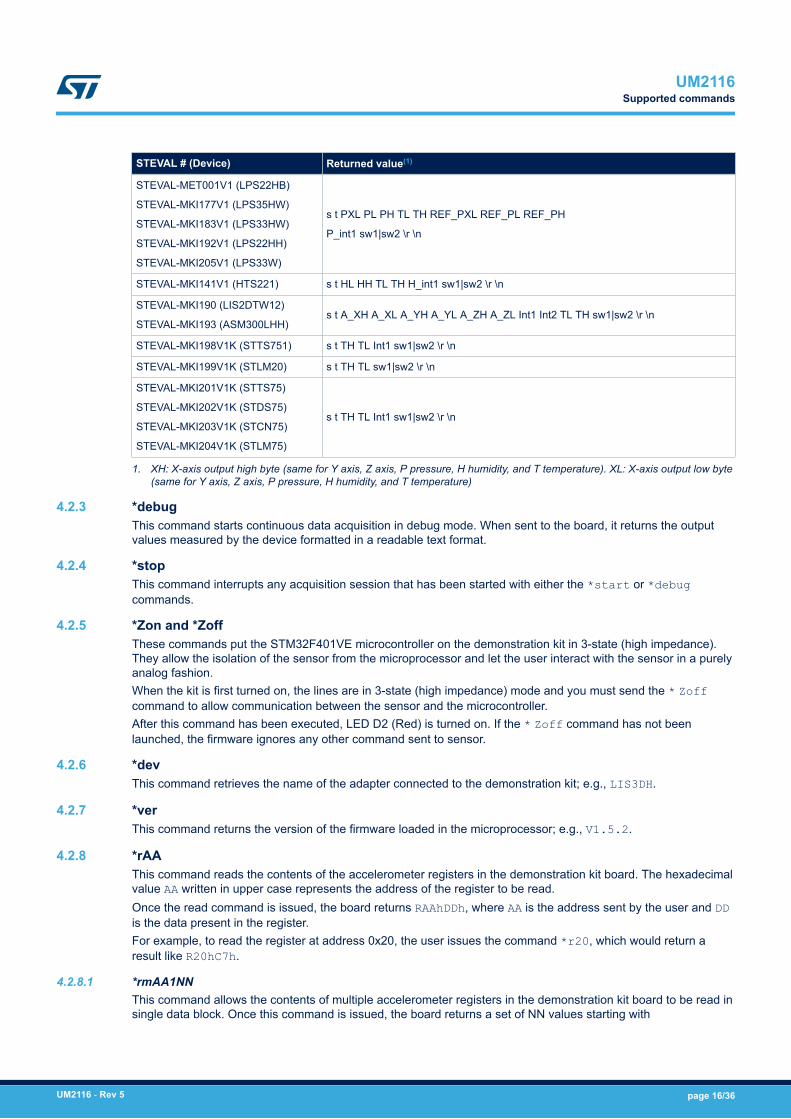
STEVAL-MET001V1 (LPS22HB)
STEVAL-MKI177V1 (LPS35HW)
STEVAL-MKI183V1 (LPS33HW)
STEVAL-MKI192V1 (LPS22HH)
STEVAL-MKI205V1 (LPS33W)
s t PXL PL PH TL TH REF_PXL REF_PL REF_PH
P_int1 sw1|sw2 \r \n
STEVAL-MKI141V1 (HTS221) s t HL HH TL TH H_int1 sw1|sw2 \r \n
STEVAL-MKI190 (LIS2DTW12)
STEVAL-MKI193 (ASM300LHH)s t A_XH A_XL A_YH A_YL A_ZH A_ZL Int1 Int2 TL TH sw1|sw2 \r \n
STEVAL-MKI198V1K (STTS751) s t TH TL Int1 sw1|sw2 \r \n
STEVAL-MKI199V1K (STLM20) s t TH TL sw1|sw2 \r \n
STEVAL-MKI201V1K (STTS75)
STEVAL-MKI202V1K (STDS75)
STEVAL-MKI203V1K (STCN75)
STEVAL-MKI204V1K (STLM75)
s t TH TL Int1 sw1|sw2 \r \n
1. XH: X-axis output high byte (same for Y axis, Z axis, P pressure, H humidity, and T temperature). XL: X-axis output low byte(same for Y axis, Z axis, P pressure, H humidity, and T temperature)
4.2.3 *debugThis command starts continuous data acquisition in debug mode. When sent to the board, it returns the outputvalues measured by the device formatted in a readable text format.
4.2.4 *stopThis command interrupts any acquisition session that has been started with either the *start or *debugcommands.
4.2.5 *Zon and *ZoffThese commands put the STM32F401VE microcontroller on the demonstration kit in 3-state (high impedance).They allow the isolation of the sensor from the microprocessor and let the user interact with the sensor in a purelyanalog fashion.When the kit is first turned on, the lines are in 3-state (high impedance) mode and you must send the * Zoffcommand to allow communication between the sensor and the microcontroller.After this command has been executed, LED D2 (Red) is turned on. If the * Zoff command has not beenlaunched, the firmware ignores any other command sent to sensor.
4.2.6 *devThis command retrieves the name of the adapter connected to the demonstration kit; e.g., LIS3DH.
4.2.7 *verThis command returns the version of the firmware loaded in the microprocessor; e.g., V1.5.2.
4.2.8 *rAAThis command reads the contents of the accelerometer registers in the demonstration kit board. The hexadecimalvalue AA written in upper case represents the address of the register to be read.Once the read command is issued, the board returns RAAhDDh, where AA is the address sent by the user and DDis the data present in the register.For example, to read the register at address 0x20, the user issues the command *r20, which would return aresult like R20hC7h.
4.2.8.1 *rmAA1NNThis command allows the contents of multiple accelerometer registers in the demonstration kit board to be read insingle data block. Once this command is issued, the board returns a set of NN values starting with
UM2116Supported commands
UM2116 - Rev 5 page 16/36
RMAA1hNNhDD1hDD2h… DDNNh where AA1 is the starting address set by user and DD1 is the data present in thisregister and so on for next registers.For example, *rm2006 reads six registers starting from 0x20, which would return a result likeRM20h06h27h00h00h00hA0h0Bh.
4.2.8.2 *multi-rAA1AA2AA3...AANThis command reads multiple accelerometer registers in the demonstration kit board in a single data block. Oncethis command is issued, the board returns set of N values starting RAA1hDD1h… AANhDDNh where AA1 is thestarting address set by user and DD1 is the data present in this register.For example, *multi-r202425292B2D reads six register starting from 0x20, which would return a result likeMULTI-R20h27h24hA0h25h0Bh29hE0h2Bh3Fh2Dh90h.
4.2.9 *wAADDThis command writes the contents of the accelerometer registers in the demonstration kit board. The hexadecimalupper case values AA and DD represent the address of the register and the data to be written, respectively.For example, *w20C7 writes 0xC7 to the register at address 0x20
4.2.10 *grAAThis command allows the contents of the gyroscope registers in the demonstration kit board to be read. Thehexadecimal, upper case AA represents the address of the register to be read.Once the read command is issued, the board returns GRAAhDDh, where AA is the address sent by the user andDD is the data present in the register.For example, *gr20 reads the register at address 0x20, which would return a result like GR20hC7h.
4.2.10.1 *grmAA1NNThis command allows the contents of multiple gyroscope registers in the demonstration kit board to be read insingle data block. Once this command is issued, the board returns set of NN values starting withGRMAA1hNNhDD1hDD2h… DDNNh where AA1 is the starting address set by user and DD1 is the data present in thisregister and so on.For example, *grm2006 reads six registers starting from 0x20, which would return a result likeGRM20h06h27h00h00h00hA0h0Bh.
4.2.10.2 *multi-grAA1AA2AA3...AANThis command reads multiple gyroscope registers in the demonstration kit board in a single data block. Once thiscommand is issued, the board returns set of N values starting with MULTI-GRAA1hDD1h… AANhDDNh where AA1is the starting address set by user and DD1 is the data present in this register and so on.For example, *multi-gr202425292B2D reads six registers starting from 0x20, which would return a result likeMULTI-GR20h27h24hA0h25h0Bh29hE0h2Bh3Fh2Dh90h.
4.2.11 *gwAADDThis command writes the contents of the gyroscope registers in the demonstration kit board. The hexadecimal,upper case. AA and DD represent the address of the register and the data to be written, respectively.For example, *gw20C7 writes 0xC7 to the register at address 0x20.
4.2.12 *mrAAThis command allows the contents of the magnetometer registers in the demonstration kit board to be read. Thehexadecimal, upper case AA represents the address of the register to be read.Once the read command is issued, the board returns MRAAhDDh, where AA is the address sent by the user andDD is the data present in the register.For example, *mr00 reads the register at address 0x00, which would return a result like MR00h10h.
4.2.12.1 *mrmAA1NNThis command readss the contents of multiple magnetometer registers in the demonstration kit board in a singledata block. Once this command is issued, the board returns set of NN values starting with RMAA1hNNhDD1hDD2h…DDNNh where AA1 is the starting address set by user and DD1 is the data present in this register.
UM2116Supported commands
UM2116 - Rev 5 page 17/36
For example, *mrm2006 reads six register starting from 0x20, which would return a result likeMRM20h06h27h00h00h00hA0h0Bh.
4.2.12.2 *multi-mrAA1AA2AA3...AANThis command reads multiple magnetometer registers in the demonstration kit board in a single data block. Oncethis command is issued, the board returns set of N values starting with MULTI-MRAA1hDD1h… AANhDDNh, whereAA1 is the starting address set by user and DD1 is the data present in this register, and so on…For example, *multi-mr202425292B2D reads six registers starting from 0x20, which would return a result likeMULTI-MR20h27h24hA0h25h0Bh29hE0h2Bh3Fh2Dh90h.
4.2.13 *mwAADDThis command writes the contents of the magnetometer registers in the demonstration kit board. Hexadecimal,upper case AA and DD represent the address of the register and the data to be written, respectively.For example, *mw0120 writes 0x20 to the register at address 0x01.
4.2.14 *prAAThis command reads the contents of the pressure sensor registers in the demonstration kit board. Thehexadecimal, upper case AA represents the address of the register to be read.Once the read command is issued, the board returns PRAAhDDh, where AA is the address sent by the user andDD is the data present in the register.For example, *pr20 reads the register at address 0x20, which would return a value like PR20h10h.
4.2.14.1 *prmAA1NNThis command reads the contents of multiple pressure sensor registers in the demonstration kit in a single datablock. Once this command is issued, the board returns set of NN values starting with PRMAA1hNNhDD1hDD2h…DDNNh where AA1 is the starting address set by user and DD1 is the data present in this register, and so on…For example, *prm2006 reads six registers starting from 0x20, which would return a value likePRM20h06h27h00h00h00hA0h0Bh.
4.2.14.2 *multi-prAA1AA2AA3...AANThis command reads multiple pressure sensor registers in the demonstration kit board in a single data block.Once this command is issued, the board returns set of N values starting with MULTI-PRAA1hDD1h… AANhDDNhwhere AA1 is the starting address set by user and DD1 is the data present in this register, and so on.For example, *multi-pr202425292B2D reads six registers starting from 0x20, which would return a result likeMULTI-PR20h27h24hA0h25h0Bh29hE0h2Bh3Fh2Dh90h.
4.2.15 *pwAADDThis command writes the contents of the pressure sensor registers in the demonstration kit board. Thehexadecimal, upper case AA and DD represent the address of the register and the data to be written, respectively.For example, *pw20C7 writes 0xC7 to the register at address 0x20.
4.2.16 *hrAAThis command reads the contents of the humidity sensor registers in the demonstration kit board. Thehexadecimal, upper case AA represents the address of the register to be read.Once the read command is issued, the board returns HRAAhDDh, where AA is the address sent by the user andDD is the data present in the register.For example, *hr20 reads the register at address 0x20, which would return a result like HR20h10h.
4.2.16.1 *hrmAA1NNThis command reads the contents of multiple humidity sensor registers in the demonstration kit board in a singledata block. Once this command is issued, the board returns set of NN values starting withHRMAA1hNNhDD1hDD2h… DDNNh where AA1 is the starting address set by user and DD1 is the data present in thisregister, and so on.For example, *hrm2006 reads six registers starting from 0x20, which would return a result likeHRM20h06h27h00h00h00hA0h0Bh.
UM2116Supported commands
UM2116 - Rev 5 page 18/36

4.2.16.2 *multi-hrAA1AA2AA3...AANThis command reads multiple humidity sensor registers in the demonstration kit board in a single data block.Once this command is issued, the board returns set of N values starting with MULTI-HRAA1hDD1h… AANhDDNhwhere AA1 is the starting address set by user and DD1 is the data present in this register, and so on.For example, *multi-hr202425292B2D reads six registers starting from 0x20, which would return a result likeMULTI-HR20h27h24hA0h25h0Bh29hE0h2Bh3Fh2Dh90h.
4.2.17 *hwAADDThis command writes the contents of the humidity sensor registers in the demonstration kit board. Thehexadecimal, upper case AA and DD represent the address of the register and the data to be written, respectively.For example *hw20C7 writes 0xC7 to the register at address 0x20.
4.2.18 *trAAThis command reads the contents of the temperature sensor registers in the demonstration kit board. Thehexadecimal, upper case AA represents the address of the register to be read. Once the read command is issued,the board returns TRAAhDDh, where AA is the address sent by the user and DD is the data present in the register.For example, *tr20 reads the register at address 0x20, which would return a result like TR20h10h.
4.2.18.1 *trmAA1NNThis command reads the contents of multiple temperature sensor registers in the demonstration kit board in asingle data block. Once this command is issued, the board returns set of NN values starting withTRMAA1hNNhDD1hDD2h… DDNNh where AA1 is the starting address set by user and DD1 is the data present in thisregister, and so on. For example, *trm2006 reads six registers starting from 0x20, which would return a resultlike TRM20h06h27h00h00h00hA0h0Bh.
4.2.18.2 *multi-trAA1AA2AA3...AANThis command reads multiple temperature sensor registers in the demonstration kit board in a single data block.Once this command is issued, the board returns set of N values starting with MULTI-TRAA1hDD1h… AANhDDNhwhere AA1 is the starting address set by user and DD1 is the data present in this register, and so on. For example,*multi-tr202425292B2D reads six registers starting from 0x20, which would return a result like MULTI-TR20h27h24hA0h25h0Bh29hE0h2Bh3Fh2Dh90h.
4.2.19 *twAADDThis command writes the contents of the temperature sensor registers in the demonstration kit board. Thehexadecimal, upper case AA and DD represent the address of the register and the data to be written, respectively.For example *tw20C7 writes 0xC7 to the register at address 0x20.
4.2.20 *singleThis command may be used to read just one set of data. It returns the read values of one data sample if thesensor is configured properly.
4.2.21 *listThe command returns the list of MKI adapters supported by the firmware in ASCII format.
4.2.22 *listdevThis command returns the list of devices supported by the firmware in ASCII format.
4.2.23 *echoonThis command is used to activate the write command verbose mode so that the firmware automatically reads thecontents of a register that has just been written to check if the write was successful.For example, * echoon launched after *w2027 returns R2027.
4.2.24 *echooffThis command stops the write command verbose mode.
UM2116Supported commands
UM2116 - Rev 5 page 19/36
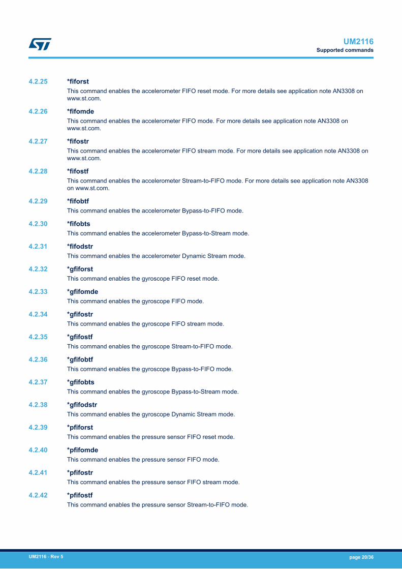
4.2.25 *fiforstThis command enables the accelerometer FIFO reset mode. For more details see application note AN3308 onwww.st.com.
4.2.26 *fifomdeThis command enables the accelerometer FIFO mode. For more details see application note AN3308 onwww.st.com.
4.2.27 *fifostrThis command enables the accelerometer FIFO stream mode. For more details see application note AN3308 onwww.st.com.
4.2.28 *fifostfThis command enables the accelerometer Stream-to-FIFO mode. For more details see application note AN3308on www.st.com.
4.2.29 *fifobtfThis command enables the accelerometer Bypass-to-FIFO mode.
4.2.30 *fifobtsThis command enables the accelerometer Bypass-to-Stream mode.
4.2.31 *fifodstrThis command enables the accelerometer Dynamic Stream mode.
4.2.32 *gfiforstThis command enables the gyroscope FIFO reset mode.
4.2.33 *gfifomdeThis command enables the gyroscope FIFO mode.
4.2.34 *gfifostrThis command enables the gyroscope FIFO stream mode.
4.2.35 *gfifostfThis command enables the gyroscope Stream-to-FIFO mode.
4.2.36 *gfifobtfThis command enables the gyroscope Bypass-to-FIFO mode.
4.2.37 *gfifobtsThis command enables the gyroscope Bypass-to-Stream mode.
4.2.38 *gfifodstrThis command enables the gyroscope Dynamic Stream mode.
4.2.39 *pfiforstThis command enables the pressure sensor FIFO reset mode.
4.2.40 *pfifomdeThis command enables the pressure sensor FIFO mode.
4.2.41 *pfifostrThis command enables the pressure sensor FIFO stream mode.
4.2.42 *pfifostfThis command enables the pressure sensor Stream-to-FIFO mode.
UM2116Supported commands
UM2116 - Rev 5 page 20/36
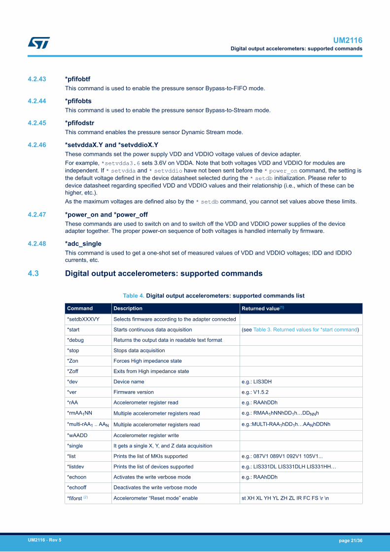
4.2.43 *pfifobtfThis command is used to enable the pressure sensor Bypass-to-FIFO mode.
4.2.44 *pfifobtsThis command is used to enable the pressure sensor Bypass-to-Stream mode.
4.2.45 *pfifodstrThis command enables the pressure sensor Dynamic Stream mode.
4.2.46 *setvddaX.Y and *setvddioX.YThese commands set the power supply VDD and VDDIO voltage values of device adapter.For example, *setvdda3.6 sets 3.6V on VDDA. Note that both voltages VDD and VDDIO for modules areindependent. If * setvdda and * setvddio have not been sent before the * power_on command, the setting isthe default voltage defined in the device datasheet selected during the * setdb initialization. Please refer todevice datasheet regarding specified VDD and VDDIO values and their relationship (i.e., which of these can behigher, etc.).As the maximum voltages are defined also by the * setdb command, you cannot set values above these limits.
4.2.47 *power_on and *power_offThese commands are used to switch on and to switch off the VDD and VDDIO power supplies of the deviceadapter together. The proper power-on sequence of both voltages is handled internally by firmware.
4.2.48 *adc_singleThis command is used to get a one-shot set of measured values of VDD and VDDIO voltages; IDD and IDDIOcurrents, etc.
4.3 Digital output accelerometers: supported commands
Table 4. Digital output accelerometers: supported commands list
Command Description Returned value(1)
*setdbXXXVY Selects firmware according to the adapter connected
*start Starts continuous data acquisition (see Table 3. Returned values for *start command)
*debug Returns the output data in readable text format
*stop Stops data acquisition
*Zon Forces High impedance state
*Zoff Exits from High impedance state
*dev Device name e.g.: LIS3DH
*ver Firmware version e.g.: V1.5.2
*rAA Accelerometer register read e.g.: RAAhDDh
*rmAA1NN Multiple accelerometer registers read e.g.: RMAA1hNNhDD1h…DDNNh
*multi-rAA1 .. AAN Multiple accelerometer registers read e.g.:MULTI-RAA1hDD1h…AANhDDNh
*wAADD Accelerometer register write
*single It gets a single X, Y, and Z data acquisition
*list Prints the list of MKIs supported e.g.: 087V1 089V1 092V1 105V1...
*listdev Prints the list of devices supported e.g.: LIS331DL LIS331DLH LIS331HH…
*echoon Activates the write verbose mode e.g.: RAAhDDh
*echooff Deactivates the write verbose mode
*fiforst (2) Accelerometer “Reset mode” enable st XH XL YH YL ZH ZL IR FC FS \r \n
UM2116Digital output accelerometers: supported commands
UM2116 - Rev 5 page 21/36
Command Description Returned value(1)
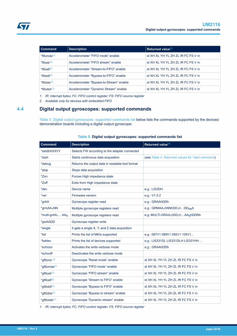
*fifomde(2) Accelerometer “FIFO mode” enable st XH XL YH YL ZH ZL IR FC FS \r \n
*fifostr(2) Accelerometer “FIFO stream” enable st XH XL YH YL ZH ZL IR FC FS \r \n
*fifostf(2) Accelerometer “Stream-to-FIFO” enable st XH XL YH YL ZH ZL IR FC FS \r \n
*fifobtf(2) Accelerometer “Bypass-to-FIFO” enable st XH XL YH YL ZH ZL IR FC FS \r \n
*fifobts(2) Accelerometer “Bypass-to-Stream” enable st XH XL YH YL ZH ZL IR FC FS \r \n
*fifodstr(2) Accelerometer “Dynamic Stream” enable st XH XL YH YL ZH ZL IR FC FS \r \n
1. IR: interrupt bytes; FC: FIFO control register; FS: FIFO source register2. Available only for devices with embedded FIFO
4.4 Digital output gyroscopes: supported commands
Table 5. Digital output gyroscopes: supported commands list below lists the commands supported by the devices/demonstration boards including a digital output gyroscope:
Table 5. Digital output gyroscopes: supported commands list
Command Description Returned value(1)
*setdbXXXVY Selects FW according to the adapter connected
*start Starts continuous data acquisition (see Table 3. Returned values for *start command)
*debug Returns the output data in readable text format
*stop Stops data acquisition
*Zon Forces High impedance state
*Zoff Exits from High impedance state
*dev Device name e.g.: LIS3DH
*ver Firmware version e.g.: V1.5.2
*grAA Gyroscope register read e.g.: GRAAhDDh
*grmAA1NN Multiple gyroscope registers read e.g.: GRMAA1hNNhDD1h…DDNNh
*multi-grAA1 .. AAN Multiple gyroscope registers read e.g.:MULTI-GRAA1hDD1h…AANhDDNh
*gwAADD Gyroscope register write
*single It gets a single X, Y, and Z data acquisition
*list Prints the list of MKIs supported e.g.: 087V1 089V1 092V1 105V1...
*listdev Prints the list of devices supported e.g.: LIS331DL LIS331DLH LIS331HH…
*echoon Activates the write verbose mode e.g.: GRAAhDDh
*echooff Deactivates the write verbose mode
*gfiforst (2) Gyroscope “Reset mode” enable st XH XL YH YL ZH ZL IR FC FS \r \n
*gfifomde(2) Gyroscope “FIFO mode” enable st XH XL YH YL ZH ZL IR FC FS \r \n
*gfifostr(2) Gyroscope “FIFO stream” enable st XH XL YH YL ZH ZL IR FC FS \r \n
*gfifostf(2) Gyroscope “Stream to FIFO” enable st XH XL YH YL ZH ZL IR FC FS \r \n
*gfifobtf(2) Gyroscope “Bypass to FIFO” enable st XH XL YH YL ZH ZL IR FC FS \r \n
*gfifobts(2) Gyroscope “Bypass to stream” enable st XH XL YH YL ZH ZL IR FC FS \r \n
*gfifodstr(2) Gyroscope “Dynamic stream” enable st XH XL YH YL ZH ZL IR FC FS \r \n
1. IR: interrupt bytes; FC: FIFO control register; FS: FIFO source register
UM2116Digital output gyroscopes: supported commands
UM2116 - Rev 5 page 22/36
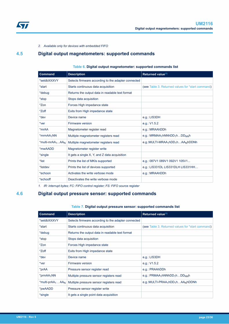
2. Available only for devices with embedded FIFO
4.5 Digital output magnetometers: supported commands
Table 6. Digital output magnetometer: supported commands list
Command Description Returned value(1)
*setdbXXXVY Selects firmware according to the adapter connected
*start Starts continuous data acquisition (see Table 3. Returned values for *start command)
*debug Returns the output data in readable text format
*stop Stops data acquisition
*Zon Forces High impedance state
*Zoff Exits from High impedance state
*dev Device name e.g.: LIS3DH
*ver Firmware version e.g.: V1.5.2
*mrAA Magnetometer register read e.g.: MRAAhDDh
*mrmAA1NN Multiple magnetometer registers read e.g.: MRMAA1hNNhDD1h…DDNNh
*multi-mrAA1...AAN Multiple magnetometer registers read e.g.:MULTI-MRAA1hDD1h…AANhDDNh
*mwAADD Magnetometer register write
*single It gets a single X, Y, and Z data acquisition
*list Prints the list of MKIs supported e.g.: 087V1 089V1 092V1 105V1...
*listdev Prints the list of devices supported e.g.: LIS331DL LIS331DLH LIS331HH…
*echoon Activates the write verbose mode e.g.: MRAAhDDh
*echooff Deactivates the write verbose mode
1. IR: interrupt bytes; FC: FIFO control register; FS: FIFO source register
4.6 Digital output pressure sensor: supported commands
Table 7. Digital output pressure sensor: supported commands list
Command Description Returned value(1)
*setdbXXXVY Selects firmware according to the adapter connected
*start Starts continuous data acquisition (see Table 3. Returned values for *start command)
*debug Returns the output data in readable text format
*stop Stops data acquisition
*Zon Forces High impedance state
*Zoff Exits from High impedance state
*dev Device name e.g.: LIS3DH
*ver Firmware version e.g.: V1.5.2
*prAA Pressure sensor register read e.g.: PRAAhDDh
*prmAA1NN Multiple pressure sensor registers read e.g.: PRMAA1hNNhDD1h…DDNNh
*multi-prAA1 .. AAN Multiple pressure sensor registers read e.g.:MULTI-PRAA1hDD1h…AANhDDNh
*pwAADD Pressure sensor register write
*single It gets a single point data acquisition
UM2116Digital output magnetometers: supported commands
UM2116 - Rev 5 page 23/36
Command Description Returned value(1)
*list Prints the list of MKIs supported e.g.: 087V1 089V1 092V1 105V1...
*listdev Prints the list of devices supported e.g.: LIS331DL LIS331DLH LIS331HH…
*echoon Activates the write verbose mode e.g.: PRAAhDDh
*echooff Deactivates the write verbose mode
*pfiforst (2) Pressure sensor “Reset mode” enable st PXL PL PH TL TH IR FC FS \r \n
*pfifomde(2) Pressure sensor “FIFO mode” enable st PXL PL PH TL TH IR FC FS \r \n
*pfifostr(2) Pressure sensor “FIFO stream” enable st PXL PL PH TL TH IR FC FS \r \n
*pfifostf(2) Pressure sensor “Stream to FIFO” enable st PXL PL PH TL TH IR FC FS \r \n
*pfifobtf(2) Pressure sensor “Bypass to FIFO” enable st PXL PL PH TL TH IR FC FS \r \n
*pfifobts(2) Pressure sensor “Bypass to stream” enable st PXL PL PH TL TH IR FC FS \r \n
*pfifodstr(2) Pressure sensor “Dynamic stream” enable st PXL PL PH TL TH IR FC FS \r \n
1. IR: interrupt bytes; FC: FIFO control register; FS: FIFO source register2. Available only for devices with embedded FIFO
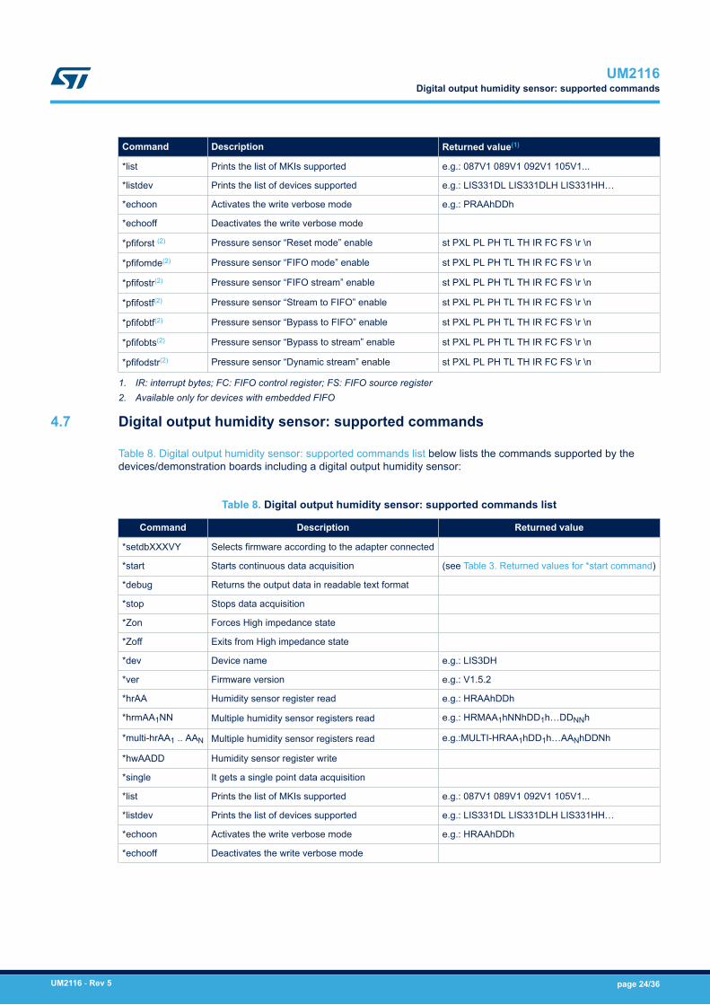
4.7 Digital output humidity sensor: supported commands
Table 8. Digital output humidity sensor: supported commands list below lists the commands supported by thedevices/demonstration boards including a digital output humidity sensor:
Table 8. Digital output humidity sensor: supported commands list
Command Description Returned value
*setdbXXXVY Selects firmware according to the adapter connected
*start Starts continuous data acquisition (see Table 3. Returned values for *start command)
*debug Returns the output data in readable text format
*stop Stops data acquisition
*Zon Forces High impedance state
*Zoff Exits from High impedance state
*dev Device name e.g.: LIS3DH
*ver Firmware version e.g.: V1.5.2
*hrAA Humidity sensor register read e.g.: HRAAhDDh
*hrmAA1NN Multiple humidity sensor registers read e.g.: HRMAA1hNNhDD1h…DDNNh
*multi-hrAA1 .. AAN Multiple humidity sensor registers read e.g.:MULTI-HRAA1hDD1h…AANhDDNh
*hwAADD Humidity sensor register write
*single It gets a single point data acquisition
*list Prints the list of MKIs supported e.g.: 087V1 089V1 092V1 105V1...
*listdev Prints the list of devices supported e.g.: LIS331DL LIS331DLH LIS331HH…
*echoon Activates the write verbose mode e.g.: HRAAhDDh
*echooff Deactivates the write verbose mode
UM2116Digital output humidity sensor: supported commands
UM2116 - Rev 5 page 24/36
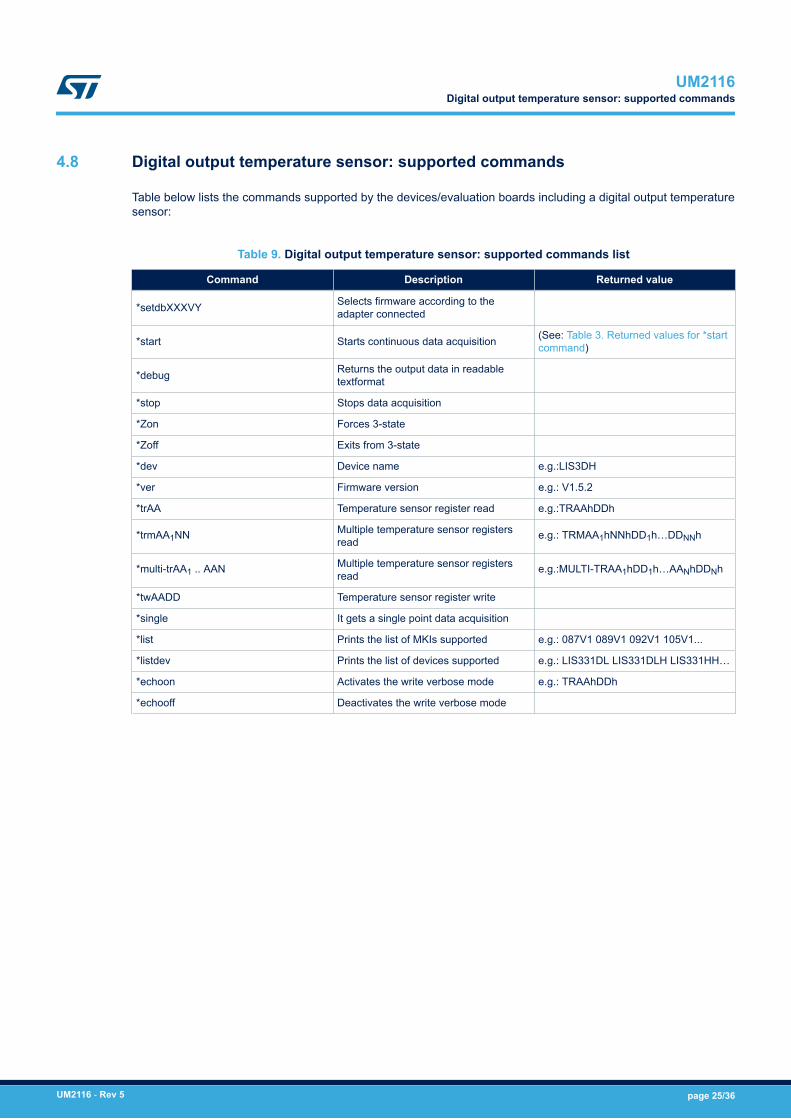
4.8 Digital output temperature sensor: supported commands
Table below lists the commands supported by the devices/evaluation boards including a digital output temperaturesensor:
Table 9. Digital output temperature sensor: supported commands list
Command Description Returned value
*setdbXXXVY Selects firmware according to theadapter connected
*start Starts continuous data acquisition (See: Table 3. Returned values for *startcommand)
*debug Returns the output data in readabletextformat
*stop Stops data acquisition
*Zon Forces 3-state
*Zoff Exits from 3-state
*dev Device name e.g.:LIS3DH
*ver Firmware version e.g.: V1.5.2
*trAA Temperature sensor register read e.g.:TRAAhDDh
*trmAA1NN Multiple temperature sensor registersread e.g.: TRMAA1hNNhDD1h…DDNNh
*multi-trAA1 .. AAN Multiple temperature sensor registersread e.g.:MULTI-TRAA1hDD1h…AANhDDNh
*twAADD Temperature sensor register write
*single It gets a single point data acquisition
*list Prints the list of MKIs supported e.g.: 087V1 089V1 092V1 105V1...
*listdev Prints the list of devices supported e.g.: LIS331DL LIS331DLH LIS331HH…
*echoon Activates the write verbose mode e.g.: TRAAhDDh
*echooff Deactivates the write verbose mode
UM2116Digital output temperature sensor: supported commands
UM2116 - Rev 5 page 25/36
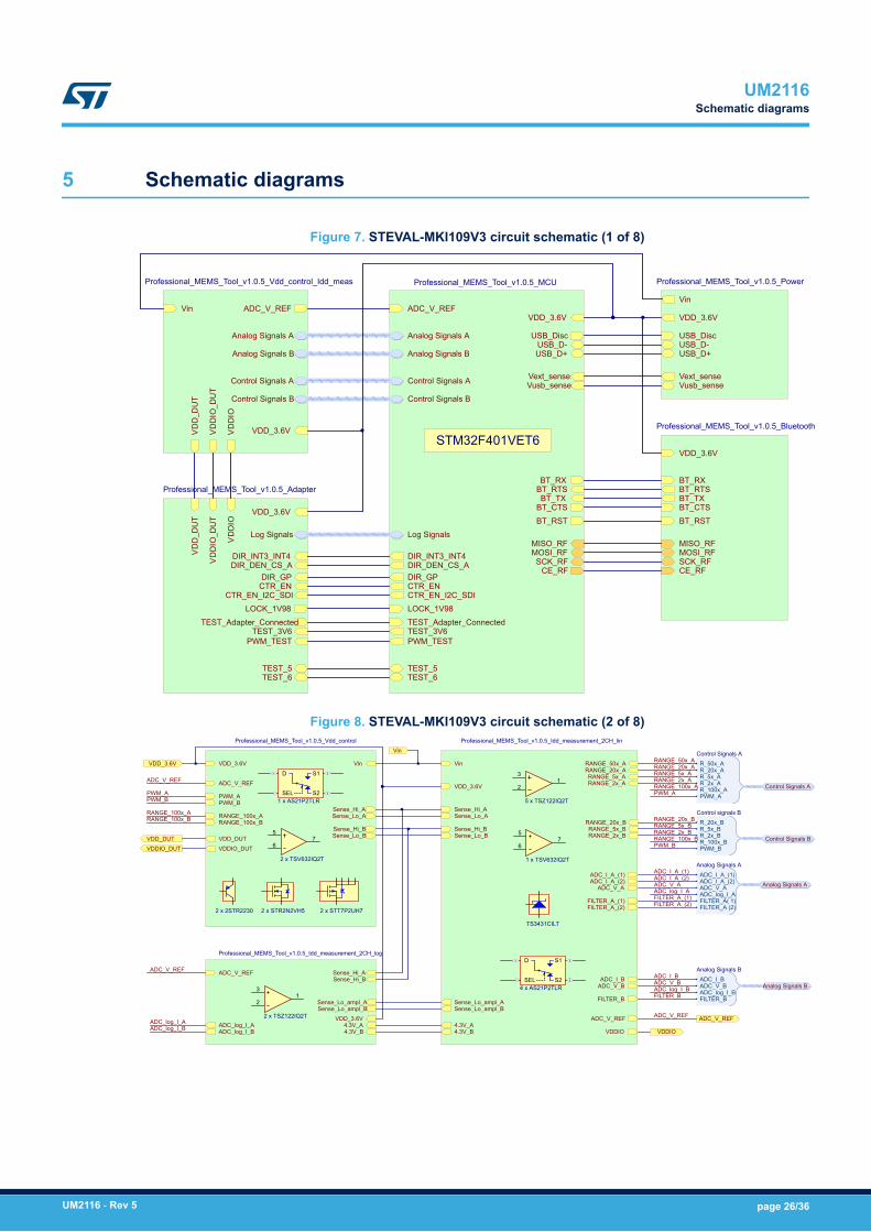
5 Schematic diagrams
Figure 7. STEVAL-MKI109V3 circuit schematic (1 of 8)
USB_D-USB_D+
USB_Disc
Vin
VDD_3.6V
Vext_senseVusb_sense
Professional_MEMS_Tool_v1.0.5_Power
BT_TXBT_RTSBT_RX
BT_CTSBT_RST
VDD_3.6V
MISO_RFMOSI_RFSCK_RFCE_RF
Professional_MEMS_Tool_v1.0.5_Bluetooth
CTR_EN
VD
D_D
UT
VD
DIO
_DU
T
VD
DIO
VDD_3.6V
DIR_GP
CTR_EN_I2C_SDILOCK_1V98
TEST_Adapter_ConnectedTEST_3V6
PWM_TEST
TEST_5TEST_6
DIR_INT3_INT4DIR_DEN_CS_A
Log Signals
Professional_MEMS_Tool_v1.0.5_Adapter
CTR_EN
BT_TXBT_RTSBT_RX
BT_CTSBT_RST
USB_D-USB_D+
USB_Disc
VDD_3.6V
Control Signals A
Control Signals B
ADC_V_REF
Analog Signals A
Analog Signals B
MISO_RF
SCK_RFMOSI_RF
CE_RFDIR_GP
CTR_EN_I2C_SDILOCK_1V98
Vext_senseVusb_sense
TEST_Adapter_ConnectedTEST_3V6PWM_TEST
TEST_5TEST_6
DIR_INT3_INT4DIR_DEN_CS_A
Log Signals
Professional_MEMS_Tool_v1.0.5_MCU
ADC_V_REF
VD
D_D
UT
VD
DIO
_DU
T
VD
DIO
Vin
Control Signals A
Control Signals B
Analog Signals A
Analog Signals B
VDD_3.6V
Professional_MEMS_Tool_v1.0.5_Vdd_control_Idd_meas
STM32F401VET6
Figure 8. STEVAL-MKI109V3 circuit schematic (2 of 8)
Vin
PWM_APWM_B
VDD_3.6V
VDDIO_DUTVDD_DUT
ADC_V_REF
Sense_Hi_B
Sense_Lo_A
Sense_Lo_B
Sense_Hi_ARANGE_100x_ARANGE_100x_B
Professional_MEMS_Tool_v1.0.5_Vdd_control
Sense_Lo_ASense_Hi_A
RANGE_2x_A
FILTER_BSense_Lo_ampl_B
Sense_Lo_B
ADC_I_A_(1)ADC_I_A_(2)
VDDIO
Sense_Lo_ampl_A
4.3V_B
FILTER_A_(1)
Vin
ADC_V_B
FILTER_A_(2)
ADC_V_REF
Sense_Hi_B
ADC_I_B
ADC_V_A
RANGE_20x_ARANGE_50x_A
RANGE_5x_B
RANGE_5x_A
RANGE_20x_B
RANGE_2x_B
4.3V_A
VDD_3.6V
Professional_MEMS_Tool_v1.0.5_Idd_measurement_2CH_lin
4.3V_A
Sense_Lo_ampl_A
ADC_log_I_B
Sense_Lo_ampl_B
4.3V_B
Sense_Hi_B
ADC_log_I_A
Sense_Hi_AADC_V_REF
VDD_3.6V
Professional_MEMS_Tool_v1.0.5_Idd_measurement_2CH_log
R_100x_A
R_20x_AR_5x_A
PWM_A
R_50x_A
R_2x_A
Control Signals A
Control Signals A
RANGE_50x_A
FILTER_A_(2)
RANGE_20x_A
RANGE_100x_APWM_A
R_100x_B
R_20x_BR_5x_B
PWM_B
R_2x_B
Control signals B
Control Signals B
RANGE_20x_B
FILTER_B
RANGE_5x_B
RANGE_100x_BPWM_B
ADC_I_A_(2)
ADC_log_I_AADC_V_A
ADC_I_A_(1)
FILTER_A( 1)FILTER_A (2)
Analog Signals A
ADC_I_A_(2)ADC_V_A
ADC_I_A_(1)
ADC_I_B
ADC_log_I_BADC_V_B
FILTER_B
Analog Signals B
Analog Signals BADC_I_BADC_V_BADC_log_I_B
RANGE_100x_ARANGE_100x_B
PWM_APWM_B
ADC_V_REF
ADC_V_REF
ADC_V_REFADC_log_I_AADC_log_I_B VDDIO
ADC_V_REF
VDDIO_DUTVDD_DUT
Vin
ADC_log_I_AAnalog Signals A
RANGE_2x_B
RANGE_5x_ARANGE_2x_A
FILTER_A_(1)
VDD_3.6V
2 x STR2N2VH5 2 x STT7P2UH72 x 2STR2230
6655
7 7
2 x TSV632IQ2T
D
SEL S2
S1
1 x AS21P2TLR
2233
1 1
2 x TSZ122IQ2T
2233
1 1
5 x TSZ122IQ2T
6655
7 7
1 x TSV632IQ2T
TS3431CILT
D
SEL S2
S1
4 x AS21P2TLR
UM2116Schematic diagrams
UM2116 - Rev 5 page 26/36
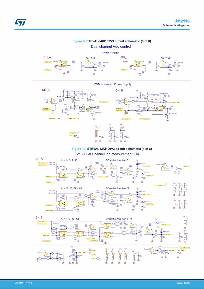
Figure 9. STEVAL-MKI109V3 circuit schematic (3 of 8)
47uFC22
GND
Dual channel Vdd control
Au = 1.20
100k
R13100k
R12
22nFC8
22nFC10
22nFC9
GND
GNDGND
100k
R31100k
R30
22nFC15
22nFC17
22nFC16
GND
GNDGND
GNDGND
GND
3.6V
470k
R25
470k
R44
6.8RR53
10R
R71
0.1% 0805
GND
5Vin
1kR70
0.1%100kR69
10uFC30
3k3R59
10RR130
10uFC25
GND
100k
R1315Vin
GND
To MEMS
100nFC23
GND
PWM + Filter
VDD_set_A VDD_set_B
47uFC32
GND
6.8RR113
10R
R94
0.1% 0805
5Vin
1kR92
0.1%100kR91
10uFC40
3k3R144
10RR140
10uFC34
GND
100k
R1325Vin
GND
100nFC33
GND
To MEMS
VDD_set_A VDD_set_B
ADC_V_REF
4.7uF
C28
4.7uF
C36
VDD_DUT VDDIO_DUT
CH_A
CH_A
CH_B
CH_B
PWM controlled Power Supply
AS21P2TLR
D 10
SEL 9
S12
S21
U5A
AS21P2TLR
D 5
SEL 4
S17
S26
U5BRef 3.00V Ref 3.00V
20kR19
20kR36
100kR22
100kR43
PDTC115EE,115
3
1
2
T12
PDTC115EE,115
3
1
2
T6
BC857BT,115
3
1
2
T3 BC857BT,115
3
1
2
T8
12
J13
12
J14
5VinVin
FB1
PWM_A PWM_B
AS2
1P2T
LRV
cc3
GN
D8
U5C
VDD_3.6V 3.6V
5Vin
GND
Au = 1.20
RANGE_100x_A
PWM_A PWM_B
RANGE_100x_B
Sense_Hi_A
Sense_Lo_A
Sense_Hi_B
Sense_Lo_B
2233
1 1
TSV632IQ2T
U1A
6655
7 7
TSV632IQ2T
U1B
84
TSV
632I
Q2T
U1C
22
33 1 1
TSV632IQ2T
U2A
66
55 7 7
TSV632IQ2T
U2B
84
TSV
632I
Q2T
U2C
100nFC77
100nFC78
22RR157
22RR158
5Vin
GND GND
100nFC79
GND
GND GND
4k7
R175
4k7
R1774k7
R604k7
R176
4k7
R1004k7
R178
100nFC99
100nFC100
3
1
2
2STR2230T4
1
3
4256
STT7P2UH7
T23
1
2
STR2N2VH5
T7
3
1
2
STR2N2VH5
T11
1
3
4256
STT7P2UH7
T10
3
1
2
2STR2230T9
Figure 10. STEVAL-MKI109V3 circuit schematic (4 of 8)
TS3431CILTU10
GND GND
5Vin_1
V1 - Dual Channel Idd measurement - linAu = 1 - 2 - 5 - 10 Differential Amp. Au = 5
Ref 3.00V
GND GNDGND
100k
R80.1%
100k
R23
0.1%
20kR7
0.1%
20k
R18
0.1%
GND
10kR20
GND
Sense_Hi_A
10k
R11
Sense_Lo_A
10k
R24
0.1%
10k
R280.1%
GND
470k
R29
470k
R1GND
GND
ADC_V_REF
Sense_Lo_BVDDIO
To Level Shifters VL
CH_A
CH_B
10uF
C39
GND
5Vin_1
GND
4.3V_A
GND
AS21P2TLR
D10
SEL9
S1 2
S2 1
U8A
AS21P2TLR
D5
SEL4
S1 7
S2 6
U8B
AS2
1P2T
LRV
cc3
GN
D8
U8C
AS2
1P2T
LRV
cc3
GN
D8
U9C
3k6R99
0.1%
5k1R95
0.1%
Ref 3.00V
120k
R97
270k
R96
470RR89
5Vin_1Vin
100pFC12
100pFC7
470nFC6
150pF
C13
GND
GND
AS2
1P2T
LRV
cc3
GN
D8
U13C 1uFC35
GND
10R
R86
22R
R98
22R
R93
10uFC41
10uFC37
4.3V_B 100nF
C38
100nF
C42
4.3V_A
4.3V_A 4.3V_B
4.3V_B4.3V_B
Sense_Hi_A
Sense_Lo_ampl_A
Sense_Lo_AADC_I_A_(1) ADC_V_A
FILTER_A_(1)RANGE_2x_A
RANGE_5x_A
GND
GND
Au = 10 - 20 - 50 - 100 Differential Amp. Au = 10
100k
R30.1%
100k
R56
0.1%
10kR57
GND
Sense_Hi_A
10k
R21
Sense_Lo_A
470k
R61
470k
R62GND
GND
AS21P2TLR
D10
SEL9
S1 2
S2 1
U13A
AS21P2TLR
D5
SEL4
S1 7
S2 6
U13B
100pFC20
100pFC19
150pF
C24
GND
470nFC21
ADC_I_A_(2)
FILTER_A_(2)RANGE_20x_A
RANGE_50x_A
GND
GND
GND
AS2
1P2T
LRV
cc3
GN
D8
U17C
4.3V_A
Au = 1 - 5 - 20 - 100 Differential Amp. Au = 5 - 10
100k
R640.1%
100k
R142
0.1%
20kR63
0.1%
20kR141
0.1%
10kR143
GND
10k
R67
10k
R148
0.1%
10k
R1500.1%
GND
470k
R151
470k
R156GND
GND
AS21P2TLR
D10
SEL9
S1 2
S2 1
U17A
AS21P2TLR
D5
SEL4
S1 7
S2 6
U17B
100pFC64
100pFC27
470nF
C26
150pF
C66
GND
Sense_Hi_B
Sense_Lo_ampl_B
Sense_Lo_BADC_I_B
ADC_V_B
FILTER_BRANGE_5x_B
RANGE_20x_B
GND
GND
Sense_Lo_B
10k
R2
0.1%
10k
R55
0.1%
AS21P2TLR
D10
SEL9
S1 2
S2 1
U9A
AS21P2TLR
D5
SEL4
S1 7
S2 6
U9B
20kR65
0.1%
20kR149
0.1%
RANGE_2x_B
4.3V_B
27k
R27
0.1%
27k
R58
0.1%
3k0R9
0.1%
4k7
R14
0.1%
82kR10
24k
R15
0.1%
3k0
R4
0.1%
2k4
R51
0.1%
300RR48
0.1%
27k
R147
0.1%
3k0
R84
0.1%
300R
R87
0.1%
1k5R85 0.1%
20kR88 0.1%
6k8R116 0.1%
137kR66
4.3V_A4.3V_A
4.3V_B
2233
1 1
TSZ122IQ2T
U3A
6655
7 7
TSZ122IQ2T
U3B
84 TS
Z122
IQ2T
U31C
2233
1 1
TSZ122IQ2T
U15A
6655
7 7
TSZ122IQ2T
U15B
GND
4.3V_A8
4 TSZ1
22IQ
2TU15C
2233
1 1
TSZ122IQ2T
U16A
6655
7 7
TSZ122IQ2T
U16B
GND
84 TS
Z122
IQ2T
U16C
2233
1 1
TSV632IQ2T
U11A
6655
7 7
TSV632IQ2T
U11B
84 TS
V63
2IQ
2T
U11C
100nFC80
22R
R159
GND
5Vin_1
4.3V_A
GND
4.3V_A
100nFC82
GND
470k
R160
GND
2233
1 1
TSZ122IQ2T
U31A
6655
7 7
TSZ122IQ2T
U31B
100kR16
100kR33 GND
4.3V_A
84 TS
Z122
IQ2T
U3C
4.3V_A
100nFC81
GND
4.3V_B
GND
84 TS
Z122
IQ2T
U32C
100kR128
10kR163
GND
10kR164
GND
10kR165
GND
2233
1 1
TSZ122IQ2T
U32A
6655
7 7
TSZ122IQ2T
U32B
GND
100nFC58
GND
100nFC67
GND
100pFC11
100R
R17
100R
R50
100R
R166
GND
100pFC65
1k5
R26
1k5
R101
Sense_Lo_A
3.6V
3.6V
3.6V
3.6V
3.6V
3.6V
100nFC87
GND
GND
1k5
R174
3.6V
GND
GND
22nFC88
22nFC91
100pFC86
VDD_3.6V
RB520S30T1GD10
RB520S30T1GD11
RB520S30T1GD12
RB520S30T1GD13
RB520S30T1GD14
RB520S30T1GD15 4.3V_B
100nFC96
GND
100nFC92
8k2R49
470RR52
0.1%
UM2116Schematic diagrams
UM2116 - Rev 5 page 27/36
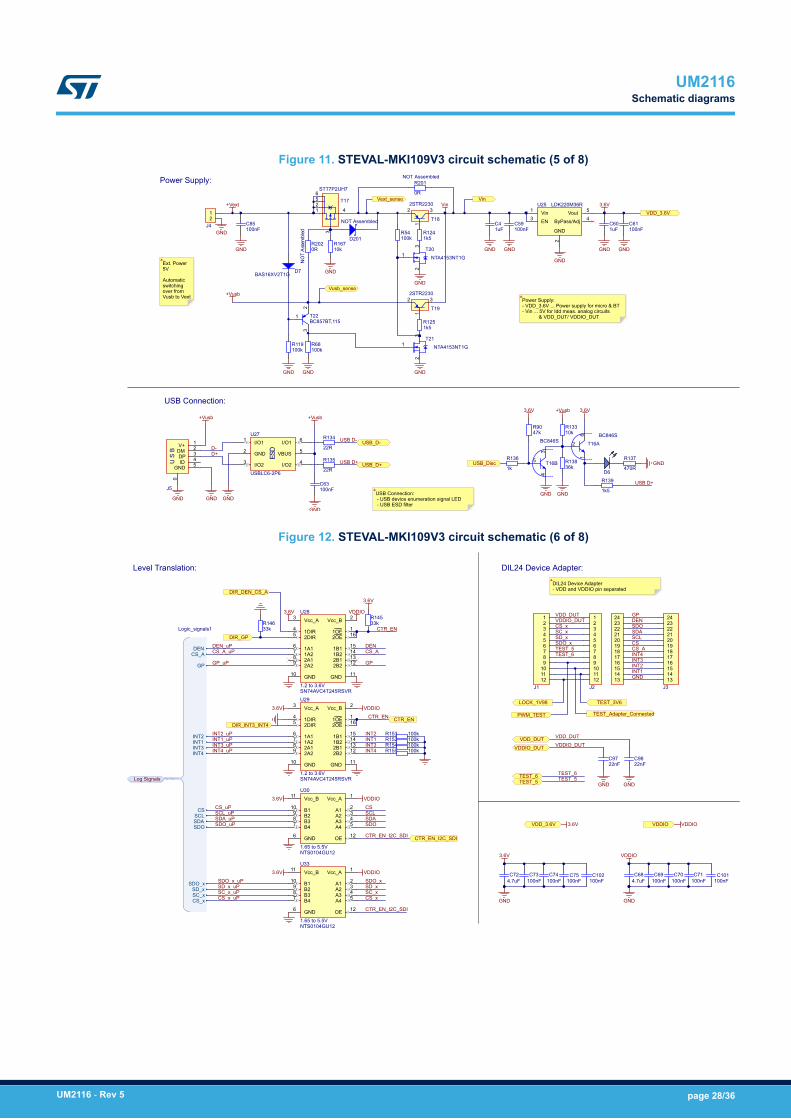
Figure 11. STEVAL-MKI109V3 circuit schematic (5 of 8)
+Vusb
Power Supply:
GND
GND
GND
3.6V
GND
GND
+Vusb
D-D+
+Vusb
USB D-
USB D+
USB Connection:+Vusb
GND
GNDGND
USB D+
3.6V 3.6V
Vin
USB_D-
USB_D+ USB_Disc
GNDGNDGND
GND
22R
R134
22R
R135
47kR90
1k
R136
10kR133
1k5
R139
470R
R137
100nFC63
100nFC59
100nFC85
1uFC4
LDK220M36RVin1
EN3
2
ByPass/Adj 4Vout 5
GND
U25+Vext Vin
GNDGND
100nFC61
1uFC60
USBLC6-2P6
I/O11
I/O23GND2
I/O2 4VBUS 5
I/O1 6
ESD
U27
VDD_3.6V
D6
DP 3DM 2V+ 1
ID 4US
B
GND 5
0
J5
BC846S6
2
1
T16ABC846S
3
5
4
T16B
1k5R124
1k5R125
GND
GND
GND
BC857BT,115
3
1
2
T22
NTA4153NT1G
3
1
2
T20
NTA4153NT1G
3
1
2
T21
100kR68
GNDGND
BAS16XV2T1G D7
100kR54
100kR119
NO
TA
ssem
bled
Vext_sense
Vusb_sense
10kR167
0RR202
0R
R201
D201
36kR138
NOT Assembled
NOT Assembled12
J4
1
3
4256
STT7P2UH7
T17
3
1
22STR2230
T18
3
1
22STR2230
T19Power Supply:- VDD_3.6V ... Power supply for micro & BT- Vin ... 5V for Idd meas. analog circuits
& VDD_DUT/ VDDIO_DUT
Ext. Power5V
Automatic switchingover from Vusb to Vext
USB Connection:- USB device enumeration signal LED- USB ESD filter
Figure 12. STEVAL-MKI109V3 circuit schematic (6 of 8)
CS_A
INT3
DEN
INT2INT1
SCLSDASDO
CS
VDD_DUT GP
INT4
VDDIO_DUT
GND
DIL24 Device Adapter:
VDDIO
CS_A_uP
INT4
DEN
INT1_uP
SCLSDASDO
GP
INT3_uP
GP_uP
DEN_uP
INT3INT4_uP
INT2_uP
VDDIO
Level Translation:
CS_uP CS
3.6V
3.6V
GP
DENCS_A
INT3INT4
CS
SDOSDASCL
INT2INT1
SDO_xSD_xSC_xCS_x
Logic_signals1
CTR_EN
SDO_uPSDA_uPSCL_uP
VDD_DUTVDDIO_DUT
VDDIO VDDIO
123456789101112
242322212019181716151413
J2
123456789
101112
J1
242322212019181716151413
J3
3.6VVDD_3.6V
VDDIO_DUTVDD_DUTINT1
INT2
SN74AVC4T245RSVR
GND10
Vcc_A3 Vcc_B 2
1B2 141B1 15
1OE 1
1A27 1A16
1DIR42DIR5
2B2 122B1 132A29 2A18
2OE 16
GND 11
U28
1.2 to 3.6V
SN74AVC4T245RSVR
GND10
Vcc_A3 Vcc_B 2
1B2 141B1 15
1OE 1
1A27 1A16
1DIR42DIR5
2B2 122B1 132A29 2A18
2OE 16
GND 11
U29
1.2 to 3.6V
NTS0104GU12
GND6
Vcc_A 1Vcc_B11
B29 B110
OE 12
A2 3A1 2
A3 4A4 5B38
B47
U30
1.65 to 5.5V
VDDIO3.6V
DIR_GP
4.7uFC72
GND
3.6V
100nFC73
100nFC74
100nFC75
4.7uFC68
GND
100nFC69
100nFC70
100nFC71
VDDIO
CS_A
33kR145
CTR_EN
CTR_EN
3.6V
33kR146
100kR152100kR153
100kR154100kR155
CTR_EN_I2C_SDI
LOCK_1V98
22nFC97
GND
22nFC98
GND
TEST_Adapter_Connected
TEST_3V6
PWM_TEST
TEST_5
TEST_5
TEST_6
TEST_6
DIR_INT3_INT4
DIR_DEN_CS_A
VDDIO3.6V
NTS0104GU12
GND6
Vcc_A 1Vcc_B11
B29 B110
OE 12
A2 3A1 2
A3 4A4 5B38
B47
U33
1.65 to 5.5V
CTR_EN_I2C_SDI
CTR_EN_I2C_SDI
CS_x_uP
SDO_x_uPSD_x_uPSC_x_uP
CS_x
SDO_xSD_xSC_x
CS_x
SDO_xSD_xSC_x
100nFC101
100nFC102
TEST_5TEST_6
Log Signals
DIL24 Device Adapter- VDD and VDDIO pin separated
UM2116Schematic diagrams
UM2116 - Rev 5 page 28/36
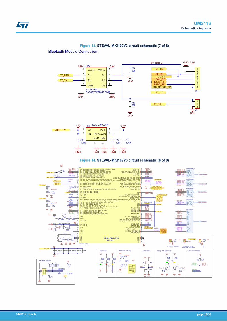
Figure 13. STEVAL-MKI109V3 circuit schematic (7 of 8)
3.6V
GND
Bluetooth Module Connection:
GND
GNDGND
3.6V
GND GND
BT_TX_s
BT_RTS_s
GND
GNDBT_TX
BT_RTS
BT_RX
BT_CTS
BT_RST 12345678
J9
GND
3.6V
GND
SCK_RFMOSI_RFMISO_RF
CE_RF
VDD_3.6V
10nFC3
SN74AVC2T244DQMR
GND5
Vcc_A 1Vcc_B8
B26B17
OE 4A2 3A1 2
U22
1.2 to 3.6V
LDK120PU25R
Vin6
EN4
2
ByPass/Adj 3Vout 1
GND
5
N/C
U19
GND
IRQ_RF / CS_SPI
CS_RF
100nFC2
100nFC1
33kR5
33kR6 1
23
J8
2.5V
2.5V
Figure 14. STEVAL-MKI109V3 circuit schematic (8 of 8)
BOOT0
JTMS_SWDIOJTCK_SWCLKJTDI
NTRST
CS_uP
SPI2_SDA
SPI2_SCLSDO_uP
JTDO
SW1
SW2
JNTRST
I2C_SCLI2C_SDA
GP_uP
GND
3.6V
BOOT0BOOT1
Not Mounted
BOOT Mode Selection:
I2C_SCLI2C_SDA
SCL_uPSDA_uP
SPI2_SCLSPI2_SDA
3.6V
I2C and SPI connection:
LED
1
3.6V 3.6V
LED
2
3.6V
LED
3
Signal LEDs:
SW1 SW2
3.6V 3.6V
GND GND
User Switches: Interrupt LED signalization:
3.6V 3.6V
GND
JTMS_SWDIOJTCK_SWCLK
GND
JTDOJTDI
JNTRSTNRST
JTAG/SWO Interface: 3.6V
CTR_EN
BT_TX
BT_RTS
BT_RXBT_CTS
BT_RST
USB_D-USB_D+
USB_Disc
1uFC43
100nFC44
100nFC52
GNDGND
GND
4.7uFC51
100nFC53
100nFC54
100nFC55
100nFC56
100nFC57
GND
3.6V
100nFC49
GND
3.6V
3.6V
ABM8-16.000MHZ-B2-T
13
24
X118pF
C47
18pF
C48GND
GND
GND
10kR120
10kR121
10kR122
10kR123
10kR129
10kR104
10kR105
10kR109
10kR110
10kR111
10kR112
4k7R117
4k7R118
100kR126
100kR127
D1 D2 D3D4 D5
330RR107
470RR108
220RR106 220R
R115330RR114
3
1
2
T143
1
2
T13
1 23 45 67 89 10
J6
BOOT1
100R
R103
FB2
1uFC45
100nFC46
22R
R102
ADC_V_REF
VDD_3.6V
SCK_RF
MOSI_RFMISO_RF
CE_RF
PWM_APWM_B
LED1
LED2LED3
CS_RFIRQ_RF / CS_SPI
INT1_uP
INT2_uP
INT2_uPINT1_uP
DIR_GP
STM32F401VET6
LQFP100
PA3 / ADC3 / USART2_RX / TIM2_CH4 / TIM5_CH4 / TIM9_CH226
VSS 74VDD75
ADC14 / PC4 33ADC15 / PC5 34
PB0 / ADC8 / TIM1_CH2N / TIM3_CH335PB1 / ADC9 / TIM1_CH3N / TIM3_CH436
PB2 / BOOT137
PB10 / SPI2_SCK / I2S2_CK / I2C2_SCL / TIM2_CH347
VCAP148
VSS 10VDD19
PB12 / SPI2_NSS / I2S2_WS / I2C2_SMBA / TIM1_BKIN51PB13 / SPI2_SCK / I2S2_CK / TIM1_CH1N52PB14 / SPI2_MISO / I2S2ext_SD / TIM1_CH2N53PB15 / SPI2_MOSI / I2S2_SD / TIM1_CH3N / RTC_REFIN54
I2S2_MCK / USART6_TX / TIM3_CH1 / SDIO_D6 / PC6 63
USART6_CK / TIM3_CH3 / SDIO_D0 / PC8 65I2S_CKIN / I2C3_SDA / TIM3_CH4 / SDIO_D1 / MCO_2 / PC9 66PA8 / I2C3_SCL / USART1_CK / TIM1_CH1 / OTG_FS_SOF / MCO_167
PA9 / I2C3_SMBA / USART1_TX / TIM1_CH2 / OTG_FS_VBUS68PA10 / USART1_RX / TIM1_CH3 / OTG_FS_ID69PA11 / USART1_CTS / USART6_TX / TIM1_CH4 / OTG_FS_DM70PA12 / USART1_RTS / USART6_RX / TIM1_ETR / OTG_FS_DP71
PA13 / *JTMS-SWDIO*72
VSS 27VDD28
PA14 / *JTCK-SWCLK*76PA15 / *JTDI* / SPI1_NSS / SPI3_NSS / I2S3_WS / TIM2_CH1/ TIM2_ETR77
SPI3_SCK / I2S3_CK / SDIO_D2 / PC10 78I2S3ext_SD / SPI3_MISO / SDIO_D3 / PC11 79
SPI3_MOSI / I2S3_SD / SDIO_CK / PC12 80
PB3 / *JTDO-SWO* / SPI1_SCK / SPI3_SCK / I2S3_CK / I2C2_SDA / TIM2_CH289PB4 / *NJTRST* / SPI1_MISO / SPI3_MISO / I2S3ext_SD / I2C3_SDA / TIM3_CH190PB5 / SPI1_MOSI / SPI3_MOSI / I2S3_SD / I2C1_SMBA / TIM3_CH291PB6 / I2C1_SCL / USART1_TX / TIM4_CH192PB7 / I2C1_SDA / USART1_RX / TIM4_CH293
Vpp / BOOT094
PB8 / I2C1_SCL / TIM4_CH3 / TIM10_CH1 SDIO_D495PB9 / SPI2_NSS / I2S2_WS / I2C1_SDA / TIM4_CH4 / TIM11_CH1 / SDIO_D596
VSS 49VDD50
VBAT6
RTC_TAMP1 / RTC_OUT / RTC_TS / PC13 7OSC32_IN / PC14 8
OSC32_OUT / PC15 9
PH0 / OSC_IN12PH1 / OSC_OUT13
NRST14
ADC10 / PC0 15ADC11 / PC1 16
ADC12 / SPI2_MISO / I2S2ext_SD / PC2 17ADC13 / SPI2_MOSI / I2S2_SD / PC3 18
VDDA22
PA0 / ADC0 / USART2_CTS / TIM2_CH1 / TIM2_ETR / TIM5_CH1 / WKUP23PA1 / ADC1 / USART2_RTS / TIM2_CH2 / TIM5_CH224PA2 / ADC2 / USART2_TX / TIM2_CH3 / TIM5_CH3 / TIM9_CH125
PA4 / ADC4 / SPI1_NSS / SPI3_NSS / I2S3_WS / USART2_CK29PA5 / ADC5 / SPI1_SCK / TIM2_CH1 / TIM2_ETR30PA6 / ADC6 / SPI1_MISO / TIM1_BKIN / TIM3_CH131PA7 / ADC7 / SPI1_MOSI / TIM1_CH1N / TIM3_CH232
SPI4_SCK / TRACECLK / PE2 1TRACED0 / PE3 2
SPI4_NSS / TRACED1 / PE4 3SPI4_MISO / TIM9_CH1 / TRACED2 / PE5 4SPI4_MOSI / TIM9_CH2 / TRACED3 / PE6 5
VSS 99VDD100
STM32F401VET6VDD11
VSSA/VREF-20VREF+21
TIM1_ETR / PE7 38TIM1_CH1N / PE8 39
TIM1_CH1 / PE9 40TIM1_CH2N / PE10 41
SPI4_NSS / TIM1_CH2 / PE11 42SPI4_SCK / TIM1_CH3N / PE12 43SPI4_MISO / TIM1_CH3 / PE13 44SPI4_MOSI / TIM1_CH4 / PE14 45
TIM1_BKIN / PE15 46
PD8 55PD9 56
PD10 57PD11 58
TIM4_CH1 / PD12 59TIM4_CH2 / PD13 60TIM4_CH3 / PD14 61TIM4_CH4 / PD15 62
I2S3_MCK / USART6_RX / TIM3_CH2 / SDIO_D7 / PC7 64
VCAP273
PD0 81PD1 82
TIM3_ETR / SDIO_CMD / PD2 83SPI2_SCK / I2S2_CK / USART2_CTS / PD3 84
USART2_RTS / PD4 85USART2_TX / PD5 86
SPI3_MOSI / I2S3_SD / USART2_RX / PD6 87USART2_CK / PD7 88
TIM4_ETR / PE0 97PE1 98
U24
12
J7
12
BT3
12
BT2
12
BT1
ADC_I_A_(2)ADC_V_A
ADC_I_A_(1)
ADC_log_I_A
ADC_I_B
ADC_V_BADC_log_I_B
RANGE_20x_BRANGE_5x_B
RANGE_2x_B
RANGE_100x_B
RANGE_50x_ARANGE_20x_A
RANGE_100x_A
RANGE_5x_ARANGE_2x_A
CS_uP
SDO_uPSDA_uPSCL_uP
INT1_uPINT2_uP
GP_uPDEN_uPCS_A_uP
INT3_uPINT4_uP
CS_A_uPDEN_uPCS_A_uP
INT3_uPINT4_uP
2.2uFC76
GND
2.2uFC50
N/A in BGA100
CTR_EN_I2C_SDI
100kR1610.1%
LOCK_1V981k
R162 100nFC84
GND
I2C3_SDA
I2C3_SDA
I2C3_SCL
I2C3_SCL
R_100x_A
R_20x_AR_5x_A
PWM_A
R_50x_A
R_2x_A
Control Signals A
Control Signals A
RANGE_50x_A
FILTER_A_(2)
RANGE_20x_A
RANGE_100x_APWM_A
R_100x_B
R_20x_BR_5x_B
PWM_B
R_2x_B
Control signals B
Control Signals B
RANGE_20x_B
FILTER_B
RANGE_5x_B
RANGE_100x_BPWM_B
ADC_I_A_(2)
ADC_log_I_AADC_V_A
ADC_I_A_(1)
FILTER_A( 1)FILTER_A (2)
Analog Signals A
ADC_I_A_(2)ADC_V_A
ADC_I_A_(1)
ADC_I_B
ADC_log_I_BADC_V_B
FILTER_B
Analog Signals B
Analog Signals BADC_I_BADC_V_BADC_log_I_B
ADC_log_I_AAnalog Signals A
RANGE_2x_B
RANGE_5x_ARANGE_2x_A
FILTER_A_(1)
FILTER_A_(1)FILTER_A_(2)
FILTER_B
Vext_sense
Vusb_sense
100kR173
100kR171
100kR170
100kR172
GND
22nFC93
GND
22nFC94
Vext_sens/2Vext_sens/2
Vusb_sens/2
Vusb_sens/2
12
J10GND
12
J12GND
Production Test Start GPI
12
J11
Production Tester
GPI
Cal
GPICal3.6V
TEST_Adapter_Connected
TEST_3V6
PWM_TEST
TEST_5
TEST_6
I2C3_SCL
DIR_DEN_CS_A
DIR_INT3_INT4
10k
R179
10k
R180
SW2
GPDENCS_A
INT3INT4
CS
SDOSDASCL
INT2INT1
SDO_xSD_xSC_xCS_x
Logic_signals1
CS_x_uP
SDO_x_uPSD_x_uPSC_x_uP
CS_x_uP
SDO_x_uPSD_x_uP
SC_x_uP
Log Signals
Interconnection Check
BOOT Mode Selection:- Default bootfrom FLASH (BOOT0 low, BOOT1 low)
UM2116Schematic diagrams
UM2116 - Rev 5 page 29/36
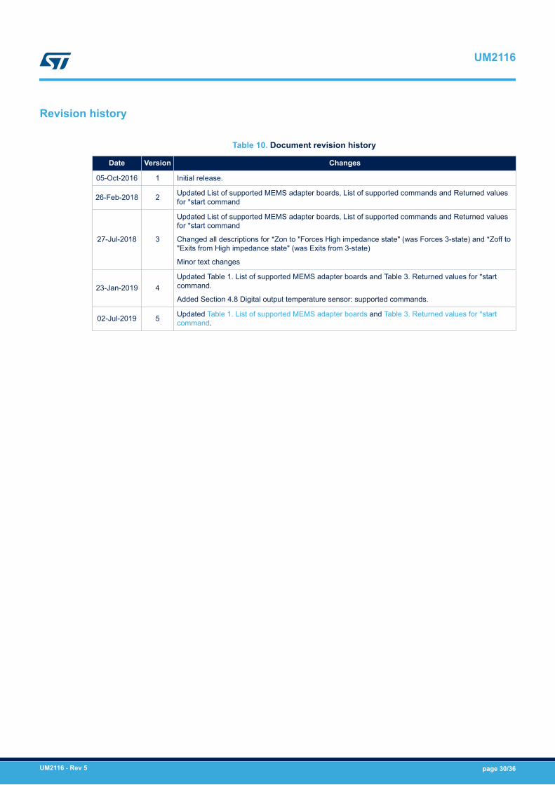
Revision history
Table 10. Document revision history
Date Version Changes
05-Oct-2016 1 Initial release.
26-Feb-2018 2 Updated List of supported MEMS adapter boards, List of supported commands and Returned valuesfor *start command
27-Jul-2018 3
Updated List of supported MEMS adapter boards, List of supported commands and Returned valuesfor *start command
Changed all descriptions for *Zon to "Forces High impedance state" (was Forces 3-state) and *Zoff to"Exits from High impedance state" (was Exits from 3-state)
Minor text changes
23-Jan-2019 4Updated Table 1. List of supported MEMS adapter boards and Table 3. Returned values for *startcommand.
Added Section 4.8 Digital output temperature sensor: supported commands.
02-Jul-2019 5 Updated Table 1. List of supported MEMS adapter boards and Table 3. Returned values for *startcommand.
UM2116
UM2116 - Rev 5 page 30/36
Contents
1 Demonstration kit description. . . . . . . . . . . . . . . . . . . . . . . . . . . . . . . . . . . . . . . . . . . . . . . . . . . . . .2
2 Professional MEMS Tool board installation. . . . . . . . . . . . . . . . . . . . . . . . . . . . . . . . . . . . . . . . .6
2.1 Hardware installation (Windows® platforms) . . . . . . . . . . . . . . . . . . . . . . . . . . . . . . . . . . . . . . . . 6
2.2 DFU. . . . . . . . . . . . . . . . . . . . . . . . . . . . . . . . . . . . . . . . . . . . . . . . . . . . . . . . . . . . . . . . . . . . . . . . . . 7
2.2.1 DFU on Windows® . . . . . . . . . . . . . . . . . . . . . . . . . . . . . . . . . . . . . . . . . . . . . . . . . . . . . . . 7
2.2.2 DFU on Linux® . . . . . . . . . . . . . . . . . . . . . . . . . . . . . . . . . . . . . . . . . . . . . . . . . . . . . . . . . . 7
2.2.3 DFU on Mac OS® . . . . . . . . . . . . . . . . . . . . . . . . . . . . . . . . . . . . . . . . . . . . . . . . . . . . . . . . 8
3 Supported MEMS adapter boards . . . . . . . . . . . . . . . . . . . . . . . . . . . . . . . . . . . . . . . . . . . . . . . . . .9
4 Supported commands . . . . . . . . . . . . . . . . . . . . . . . . . . . . . . . . . . . . . . . . . . . . . . . . . . . . . . . . . . . .11
4.1 Getting started . . . . . . . . . . . . . . . . . . . . . . . . . . . . . . . . . . . . . . . . . . . . . . . . . . . . . . . . . . . . . . . . 11
4.1.1 Quick start. . . . . . . . . . . . . . . . . . . . . . . . . . . . . . . . . . . . . . . . . . . . . . . . . . . . . . . . . . . . . 11
4.2 Supported commands. . . . . . . . . . . . . . . . . . . . . . . . . . . . . . . . . . . . . . . . . . . . . . . . . . . . . . . . . . 11
4.2.1 *setdbXXXVY . . . . . . . . . . . . . . . . . . . . . . . . . . . . . . . . . . . . . . . . . . . . . . . . . . . . . . . . . . 13
4.2.2 *start . . . . . . . . . . . . . . . . . . . . . . . . . . . . . . . . . . . . . . . . . . . . . . . . . . . . . . . . . . . . . . . . . 13
4.2.3 *debug . . . . . . . . . . . . . . . . . . . . . . . . . . . . . . . . . . . . . . . . . . . . . . . . . . . . . . . . . . . . . . . 16
4.2.4 *stop . . . . . . . . . . . . . . . . . . . . . . . . . . . . . . . . . . . . . . . . . . . . . . . . . . . . . . . . . . . . . . . . . 16
4.2.5 *Zon and *Zoff. . . . . . . . . . . . . . . . . . . . . . . . . . . . . . . . . . . . . . . . . . . . . . . . . . . . . . . . . . 16
4.2.6 *dev . . . . . . . . . . . . . . . . . . . . . . . . . . . . . . . . . . . . . . . . . . . . . . . . . . . . . . . . . . . . . . . . . 16
4.2.7 *ver . . . . . . . . . . . . . . . . . . . . . . . . . . . . . . . . . . . . . . . . . . . . . . . . . . . . . . . . . . . . . . . . . . 16
4.2.8 *rAA . . . . . . . . . . . . . . . . . . . . . . . . . . . . . . . . . . . . . . . . . . . . . . . . . . . . . . . . . . . . . . . . . 16
4.2.9 *wAADD . . . . . . . . . . . . . . . . . . . . . . . . . . . . . . . . . . . . . . . . . . . . . . . . . . . . . . . . . . . . . . 17
4.2.10 *grAA . . . . . . . . . . . . . . . . . . . . . . . . . . . . . . . . . . . . . . . . . . . . . . . . . . . . . . . . . . . . . . . . 17
4.2.11 *gwAADD . . . . . . . . . . . . . . . . . . . . . . . . . . . . . . . . . . . . . . . . . . . . . . . . . . . . . . . . . . . . . 17
4.2.12 *mrAA . . . . . . . . . . . . . . . . . . . . . . . . . . . . . . . . . . . . . . . . . . . . . . . . . . . . . . . . . . . . . . . . 17
4.2.13 *mwAADD. . . . . . . . . . . . . . . . . . . . . . . . . . . . . . . . . . . . . . . . . . . . . . . . . . . . . . . . . . . . . 18
4.2.14 *prAA . . . . . . . . . . . . . . . . . . . . . . . . . . . . . . . . . . . . . . . . . . . . . . . . . . . . . . . . . . . . . . . . 18
4.2.15 *pwAADD . . . . . . . . . . . . . . . . . . . . . . . . . . . . . . . . . . . . . . . . . . . . . . . . . . . . . . . . . . . . . 18
4.2.16 *hrAA . . . . . . . . . . . . . . . . . . . . . . . . . . . . . . . . . . . . . . . . . . . . . . . . . . . . . . . . . . . . . . . . 18
4.2.17 *hwAADD . . . . . . . . . . . . . . . . . . . . . . . . . . . . . . . . . . . . . . . . . . . . . . . . . . . . . . . . . . . . . 19
4.2.18 *trAA . . . . . . . . . . . . . . . . . . . . . . . . . . . . . . . . . . . . . . . . . . . . . . . . . . . . . . . . . . . . . . . . . 19
UM2116Contents
UM2116 - Rev 5 page 31/36
4.2.19 *twAADD. . . . . . . . . . . . . . . . . . . . . . . . . . . . . . . . . . . . . . . . . . . . . . . . . . . . . . . . . . . . . . 19
4.2.20 *single . . . . . . . . . . . . . . . . . . . . . . . . . . . . . . . . . . . . . . . . . . . . . . . . . . . . . . . . . . . . . . . . 19
4.2.21 *list . . . . . . . . . . . . . . . . . . . . . . . . . . . . . . . . . . . . . . . . . . . . . . . . . . . . . . . . . . . . . . . . . . 19
4.2.22 *listdev . . . . . . . . . . . . . . . . . . . . . . . . . . . . . . . . . . . . . . . . . . . . . . . . . . . . . . . . . . . . . . . 19
4.2.23 *echoon. . . . . . . . . . . . . . . . . . . . . . . . . . . . . . . . . . . . . . . . . . . . . . . . . . . . . . . . . . . . . . . 19
4.2.24 *echooff. . . . . . . . . . . . . . . . . . . . . . . . . . . . . . . . . . . . . . . . . . . . . . . . . . . . . . . . . . . . . . . 19
4.2.25 *fiforst . . . . . . . . . . . . . . . . . . . . . . . . . . . . . . . . . . . . . . . . . . . . . . . . . . . . . . . . . . . . . . . . 19
4.2.26 *fifomde. . . . . . . . . . . . . . . . . . . . . . . . . . . . . . . . . . . . . . . . . . . . . . . . . . . . . . . . . . . . . . . 20
4.2.27 *fifostr . . . . . . . . . . . . . . . . . . . . . . . . . . . . . . . . . . . . . . . . . . . . . . . . . . . . . . . . . . . . . . . . 20
4.2.28 *fifostf . . . . . . . . . . . . . . . . . . . . . . . . . . . . . . . . . . . . . . . . . . . . . . . . . . . . . . . . . . . . . . . . 20
4.2.29 *fifobtf . . . . . . . . . . . . . . . . . . . . . . . . . . . . . . . . . . . . . . . . . . . . . . . . . . . . . . . . . . . . . . . . 20
4.2.30 *fifobts. . . . . . . . . . . . . . . . . . . . . . . . . . . . . . . . . . . . . . . . . . . . . . . . . . . . . . . . . . . . . . . . 20
4.2.31 *fifodstr . . . . . . . . . . . . . . . . . . . . . . . . . . . . . . . . . . . . . . . . . . . . . . . . . . . . . . . . . . . . . . . 20
4.2.32 *gfiforst . . . . . . . . . . . . . . . . . . . . . . . . . . . . . . . . . . . . . . . . . . . . . . . . . . . . . . . . . . . . . . . 20
4.2.33 *gfifomde. . . . . . . . . . . . . . . . . . . . . . . . . . . . . . . . . . . . . . . . . . . . . . . . . . . . . . . . . . . . . . 20
4.2.34 *gfifostr . . . . . . . . . . . . . . . . . . . . . . . . . . . . . . . . . . . . . . . . . . . . . . . . . . . . . . . . . . . . . . . 20
4.2.35 *gfifostf . . . . . . . . . . . . . . . . . . . . . . . . . . . . . . . . . . . . . . . . . . . . . . . . . . . . . . . . . . . . . . . 20
4.2.36 *gfifobtf . . . . . . . . . . . . . . . . . . . . . . . . . . . . . . . . . . . . . . . . . . . . . . . . . . . . . . . . . . . . . . . 20
4.2.37 *gfifobts. . . . . . . . . . . . . . . . . . . . . . . . . . . . . . . . . . . . . . . . . . . . . . . . . . . . . . . . . . . . . . . 20
4.2.38 *gfifodstr . . . . . . . . . . . . . . . . . . . . . . . . . . . . . . . . . . . . . . . . . . . . . . . . . . . . . . . . . . . . . . 20
4.2.39 *pfiforst . . . . . . . . . . . . . . . . . . . . . . . . . . . . . . . . . . . . . . . . . . . . . . . . . . . . . . . . . . . . . . . 20
4.2.40 *pfifomde. . . . . . . . . . . . . . . . . . . . . . . . . . . . . . . . . . . . . . . . . . . . . . . . . . . . . . . . . . . . . . 20
4.2.41 *pfifostr . . . . . . . . . . . . . . . . . . . . . . . . . . . . . . . . . . . . . . . . . . . . . . . . . . . . . . . . . . . . . . . 20
4.2.42 *pfifostf . . . . . . . . . . . . . . . . . . . . . . . . . . . . . . . . . . . . . . . . . . . . . . . . . . . . . . . . . . . . . . . 20
4.2.43 *pfifobtf . . . . . . . . . . . . . . . . . . . . . . . . . . . . . . . . . . . . . . . . . . . . . . . . . . . . . . . . . . . . . . . 20
4.2.44 *pfifobts. . . . . . . . . . . . . . . . . . . . . . . . . . . . . . . . . . . . . . . . . . . . . . . . . . . . . . . . . . . . . . . 21
4.2.45 *pfifodstr . . . . . . . . . . . . . . . . . . . . . . . . . . . . . . . . . . . . . . . . . . . . . . . . . . . . . . . . . . . . . . 21
4.2.46 *setvddaX.Y and *setvddioX.Y . . . . . . . . . . . . . . . . . . . . . . . . . . . . . . . . . . . . . . . . . . . . . 21
4.2.47 *power_on and *power_off . . . . . . . . . . . . . . . . . . . . . . . . . . . . . . . . . . . . . . . . . . . . . . . . 21
4.2.48 *adc_single . . . . . . . . . . . . . . . . . . . . . . . . . . . . . . . . . . . . . . . . . . . . . . . . . . . . . . . . . . . . 21
4.3 Digital output accelerometers: supported commands. . . . . . . . . . . . . . . . . . . . . . . . . . . . . . . . 21
4.4 Digital output gyroscopes: supported commands . . . . . . . . . . . . . . . . . . . . . . . . . . . . . . . . . . . 22
UM2116Contents
UM2116 - Rev 5 page 32/36
4.5 Digital output magnetometers: supported commands . . . . . . . . . . . . . . . . . . . . . . . . . . . . . . . 23
4.6 Digital output pressure sensor: supported commands . . . . . . . . . . . . . . . . . . . . . . . . . . . . . . . 23
4.7 Digital output humidity sensor: supported commands . . . . . . . . . . . . . . . . . . . . . . . . . . . . . . . 24
4.8 Digital output temperature sensor: supported commands . . . . . . . . . . . . . . . . . . . . . . . . . . . . 24
5 Schematic diagrams . . . . . . . . . . . . . . . . . . . . . . . . . . . . . . . . . . . . . . . . . . . . . . . . . . . . . . . . . . . . . .26
Revision history . . . . . . . . . . . . . . . . . . . . . . . . . . . . . . . . . . . . . . . . . . . . . . . . . . . . . . . . . . . . . . . . . . . . . . .30
UM2116Contents
UM2116 - Rev 5 page 33/36
List of tablesTable 1. List of supported MEMS adapter boards . . . . . . . . . . . . . . . . . . . . . . . . . . . . . . . . . . . . . . . . . . . . . . . . . . . . 9Table 2. List of supported commands . . . . . . . . . . . . . . . . . . . . . . . . . . . . . . . . . . . . . . . . . . . . . . . . . . . . . . . . . . . 12Table 3. Returned values for *start command. . . . . . . . . . . . . . . . . . . . . . . . . . . . . . . . . . . . . . . . . . . . . . . . . . . . . . 14Table 4. Digital output accelerometers: supported commands list . . . . . . . . . . . . . . . . . . . . . . . . . . . . . . . . . . . . . . . . 21Table 5. Digital output gyroscopes: supported commands list . . . . . . . . . . . . . . . . . . . . . . . . . . . . . . . . . . . . . . . . . . . 22Table 6. Digital output magnetometer: supported commands list. . . . . . . . . . . . . . . . . . . . . . . . . . . . . . . . . . . . . . . . . 23Table 7. Digital output pressure sensor: supported commands list . . . . . . . . . . . . . . . . . . . . . . . . . . . . . . . . . . . . . . . 23Table 8. Digital output humidity sensor: supported commands list . . . . . . . . . . . . . . . . . . . . . . . . . . . . . . . . . . . . . . . . 24Table 9. Digital output temperature sensor: supported commands list . . . . . . . . . . . . . . . . . . . . . . . . . . . . . . . . . . . . . 25Table 10. Document revision history . . . . . . . . . . . . . . . . . . . . . . . . . . . . . . . . . . . . . . . . . . . . . . . . . . . . . . . . . . . . . 30
UM2116List of tables
UM2116 - Rev 5 page 34/36
List of figuresFigure 1. Demonstration board block diagram . . . . . . . . . . . . . . . . . . . . . . . . . . . . . . . . . . . . . . . . . . . . . . . . . . . . . 2Figure 2. Top silkscreen of the Professional MEMS Tool kit . . . . . . . . . . . . . . . . . . . . . . . . . . . . . . . . . . . . . . . . . . . . 3Figure 3. Top view of Professional MEMS Tool kit . . . . . . . . . . . . . . . . . . . . . . . . . . . . . . . . . . . . . . . . . . . . . . . . . . . 4Figure 4. How to plug the DIL24 adapter on STEVAL-MKI109V3 . . . . . . . . . . . . . . . . . . . . . . . . . . . . . . . . . . . . . . . . 5Figure 5. Successful device driver installation . . . . . . . . . . . . . . . . . . . . . . . . . . . . . . . . . . . . . . . . . . . . . . . . . . . . . 6Figure 6. Virtual COM port assignment . . . . . . . . . . . . . . . . . . . . . . . . . . . . . . . . . . . . . . . . . . . . . . . . . . . . . . . . . . 7Figure 7. STEVAL-MKI109V3 circuit schematic (1 of 8) . . . . . . . . . . . . . . . . . . . . . . . . . . . . . . . . . . . . . . . . . . . . . . 26Figure 8. STEVAL-MKI109V3 circuit schematic (2 of 8) . . . . . . . . . . . . . . . . . . . . . . . . . . . . . . . . . . . . . . . . . . . . . . 26Figure 9. STEVAL-MKI109V3 circuit schematic (3 of 8) . . . . . . . . . . . . . . . . . . . . . . . . . . . . . . . . . . . . . . . . . . . . . . 27Figure 10. STEVAL-MKI109V3 circuit schematic (4 of 8) . . . . . . . . . . . . . . . . . . . . . . . . . . . . . . . . . . . . . . . . . . . . . . 27Figure 11. STEVAL-MKI109V3 circuit schematic (5 of 8) . . . . . . . . . . . . . . . . . . . . . . . . . . . . . . . . . . . . . . . . . . . . . . 28Figure 12. STEVAL-MKI109V3 circuit schematic (6 of 8) . . . . . . . . . . . . . . . . . . . . . . . . . . . . . . . . . . . . . . . . . . . . . . 28Figure 13. STEVAL-MKI109V3 circuit schematic (7 of 8) . . . . . . . . . . . . . . . . . . . . . . . . . . . . . . . . . . . . . . . . . . . . . . 29Figure 14. STEVAL-MKI109V3 circuit schematic (8 of 8) . . . . . . . . . . . . . . . . . . . . . . . . . . . . . . . . . . . . . . . . . . . . . . 29
UM2116List of figures
UM2116 - Rev 5 page 35/36

IMPORTANT NOTICE – PLEASE READ CAREFULLY
STMicroelectronics NV and its subsidiaries (“ST”) reserve the right to make changes, corrections, enhancements, modifications, and improvements to STproducts and/or to this document at any time without notice. Purchasers should obtain the latest relevant information on ST products before placing orders. STproducts are sold pursuant to ST’s terms and conditions of sale in place at the time of order acknowledgement.
Purchasers are solely responsible for the choice, selection, and use of ST products and ST assumes no liability for application assistance or the design ofPurchasers’ products.
No license, express or implied, to any intellectual property right is granted by ST herein.
Resale of ST products with provisions different from the information set forth herein shall void any warranty granted by ST for such product.
ST and the ST logo are trademarks of ST. For additional information about ST trademarks, please refer to www.st.com/trademarks. All other product or servicenames are the property of their respective owners.
Information in this document supersedes and replaces information previously supplied in any prior versions of this document.
© 2019 STMicroelectronics – All rights reserved
UM2116
UM2116 - Rev 5 page 36/36