Embed Size (px)
Citation preview
GE EMERGENCY LIGHTING SYSTEM
Steve Benner- [email protected]
Kevin Greene- [email protected]
Ernest Hauser- [email protected]
Aleksey Ryzhakov- [email protected]
Abdulla Al Hosani- [email protected]
04/29/2008
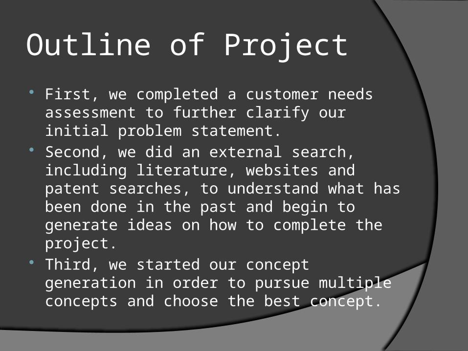
Outline of Project First, we completed a customer needs
assessment to further clarify our initial problem statement.
Second, we did an external search, including literature, websites and patent searches, to understand what has been done in the past and begin to generate ideas on how to complete the project.
Third, we started our concept generation in order to pursue multiple concepts and choose the best concept.
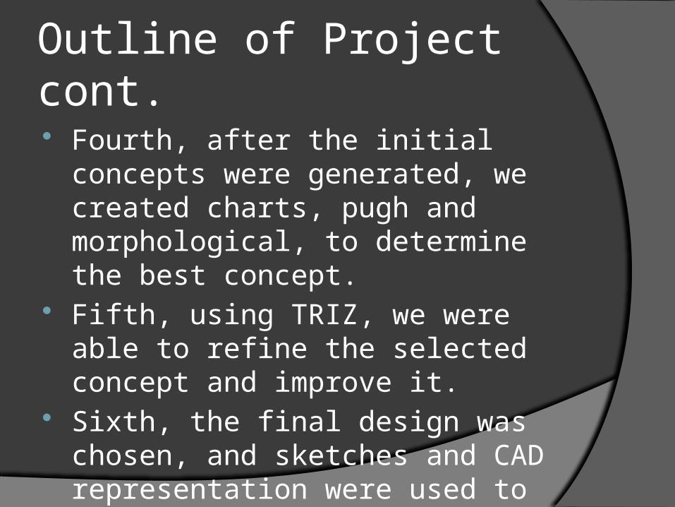
Outline of Project cont.
Fourth, after the initial concepts were generated, we created charts, pugh and morphological, to determine the best concept.
Fifth, using TRIZ, we were able to refine the selected concept and improve it.
Sixth, the final design was chosen, and sketches and CAD representation were used to convey our idea.
Outline of Project cont.
Finally, we used the final design to create a bill of materials and a material selection chart, thus calculating the cost of the lighting system.

Project Management
Steve Benner- Team Leader
Kevin Greene- Research and Bill of Materials
Ernest Hauser- Concept Selection
Aleksey Ryzhakov- CAD and Final Design
Abdulla Al Hosani- Customer Needs
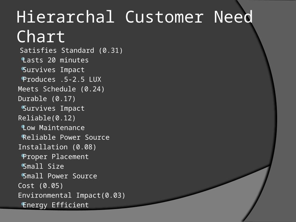
Hierarchal Customer Need Chart
Satisfies Standard (0.31) Lasts 20 minutes Survives Impact Produces .5-2.5 LUX
Meets Schedule (0.24)
Durable (0.17) Survives Impact
Reliable(0.12) Low Maintenance Reliable Power Source
Installation (0.08) Proper Placement Small Size Small Power Source
Cost (0.05)
Environmental Impact(0.03) Energy Efficient
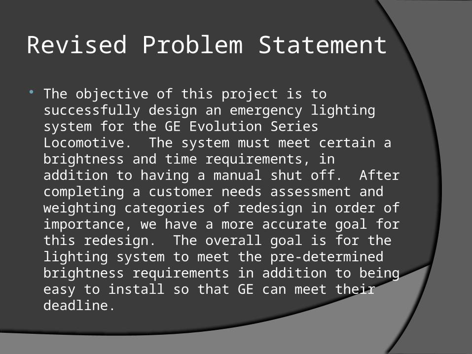
Revised Problem Statement
The objective of this project is to successfully design an emergency lighting system for the GE Evolution Series Locomotive. The system must meet certain a brightness and time requirements, in addition to having a manual shut off. After completing a customer needs assessment and weighting categories of redesign in order of importance, we have a more accurate goal for this redesign. The overall goal is for the lighting system to meet the pre-determined brightness requirements in addition to being easy to install so that GE can meet their deadline.
Auto Shut Off
Break Activation
Battery Housing
Light Housing
Crash
Chemical Energy Stored in Chemicals
Chemical Reaction Begins
Located in Back Energy Created
LED Illuminates
Circuit CompleteProtects Lights
Circuit Breaks if Signal Present
Residual Shock
LIGHTi
EMS Diagram
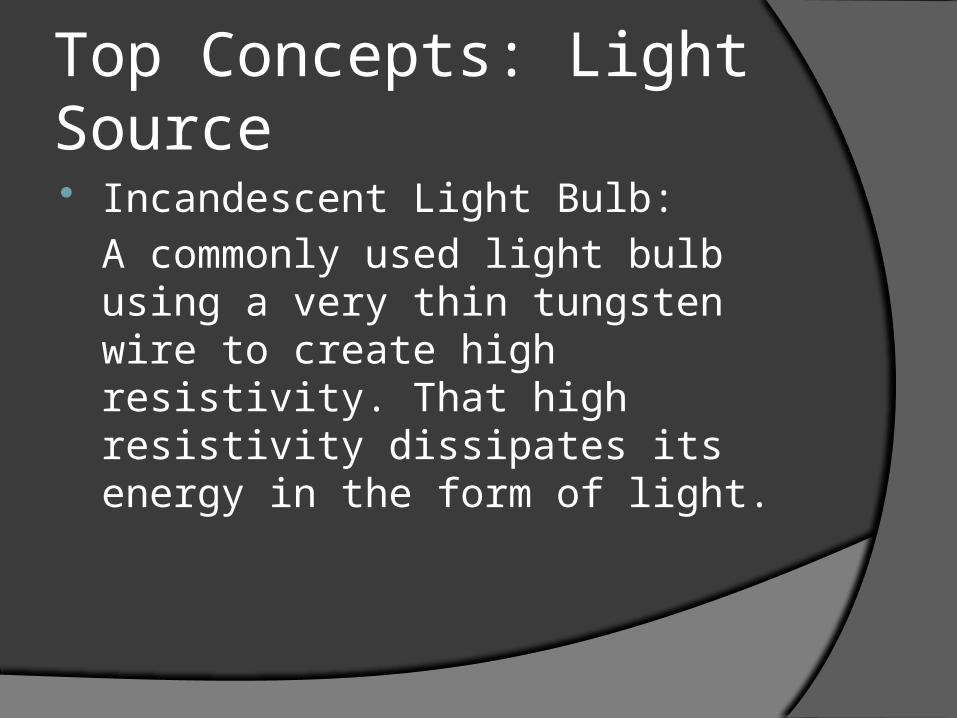
Top Concepts: Light Source Incandescent Light Bulb:
A commonly used light bulb using a very thin tungsten wire to create high resistivity. That high resistivity dissipates its energy in the form of light.
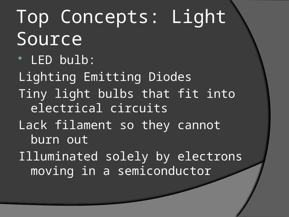
Top Concepts: Light Source LED bulb:
Lighting Emitting Diodes
Tiny light bulbs that fit into electrical circuits
Lack filament so they cannot burn out
Illuminated solely by electrons moving in a semiconductor
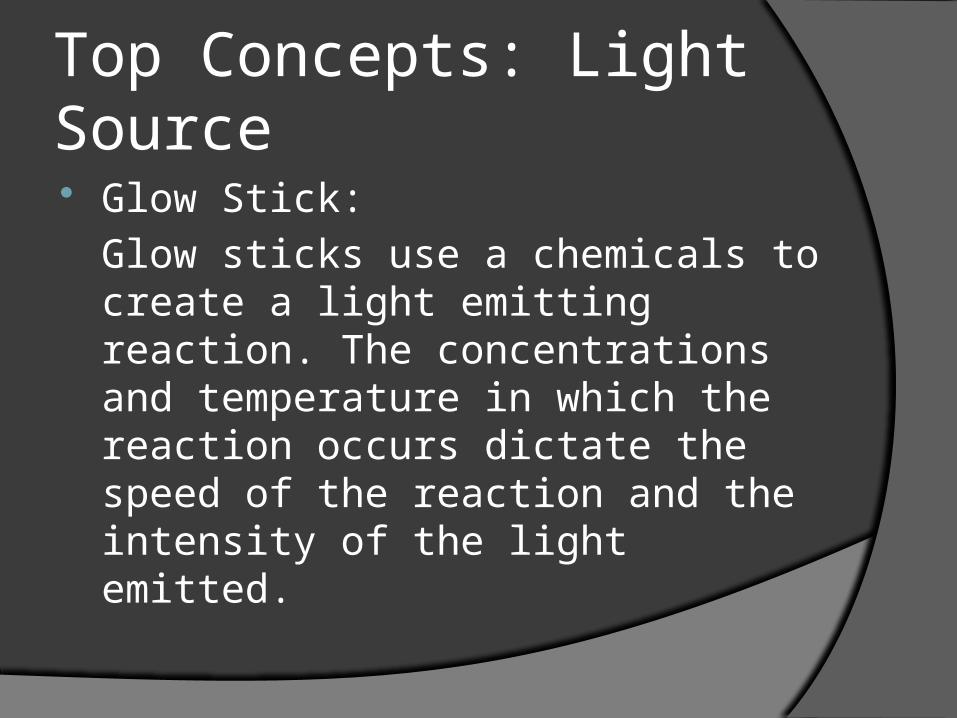
Top Concepts: Light Source Glow Stick:
Glow sticks use a chemicals to create a light emitting reaction. The concentrations and temperature in which the reaction occurs dictate the speed of the reaction and the intensity of the light emitted.
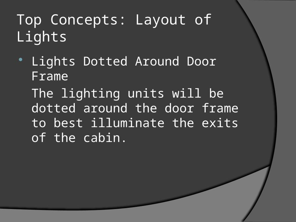
Top Concepts: Layout of Lights
Lights Dotted Around Door Frame
The lighting units will be dotted around the door frame to best illuminate the exits of the cabin.
Top Concepts: Layout of Lights
Cradle:
The design of the cradle houses nine LED bulbs and uses a mirror to focus the light on the walkway and stairs area. The cradle also uses steel bars to protect the unit in a crash environment.
Top Concepts: Layout of Lights
Standard Wall Mount:
The lights will be placed on the walls of the cabin with a protective steel cover. The cover will also serve to direct the light down towards the walkway and stairs.
Top Concepts: Layout of Lights
Floor Mount:
The lights will be installed into the floor of the cabin area and outline the walkway and stairs. A transparent cover will provide protection in a crash environment.
Top Concepts: Power Source
Solar Panel:
Installed on the outside of the train cabin, the solar panels will use the energy given off by the sun to power the emergency lighting system.

Top Concepts: Power Source
Battery (Li-ion):
The electrodes of a lithium-ion battery are made of lightweight lithium and carbon. The lithium is a light weight material that is very reactive. This means it can store a lot of energy.
Top Concepts: Power Source
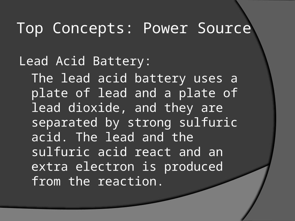
Lead Acid Battery:
The lead acid battery uses a plate of lead and a plate of lead dioxide, and they are separated by strong sulfuric acid. The lead and the sulfuric acid react and an extra electron is produced from the reaction.
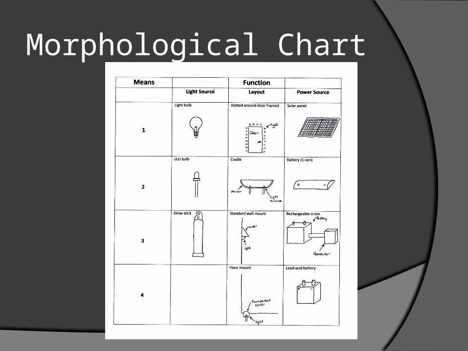
Morphological Chart
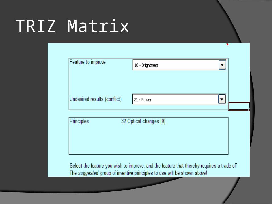
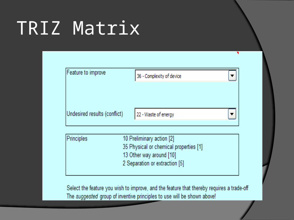
TRIZ Matrix
TRIZ Principles: Optical changes have been
suggested. Idea: Incorporate underside mirrors (or
reflective surfaces) on the protective bars that transverse the light unit so that the light from the LEDs strikes the bottom of those bars, reflects back into the unit, and then reflects once again into open space. Also incorporate mirrors (or reflective surfaces) inside the light unit itself. This will capture any stray light and navigate it out into open environment.
TRIZ Matrix
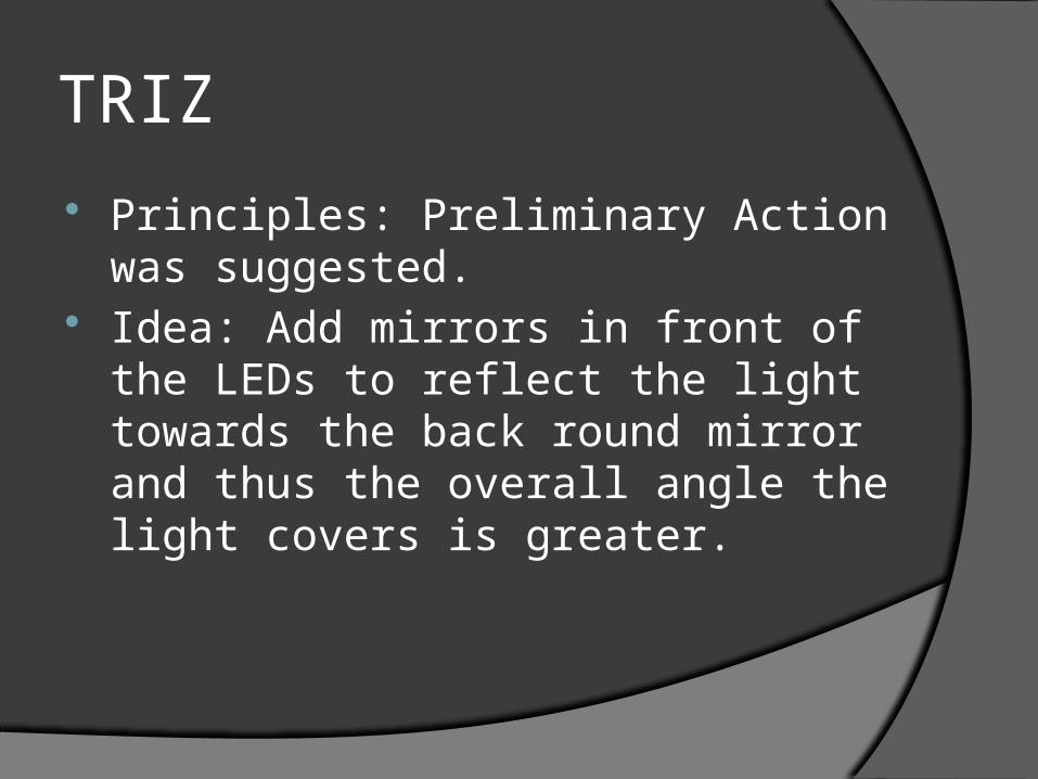
TRIZ
Principles: Preliminary Action was suggested.
Idea: Add mirrors in front of the LEDs to reflect the light towards the back round mirror and thus the overall angle the light covers is greater.
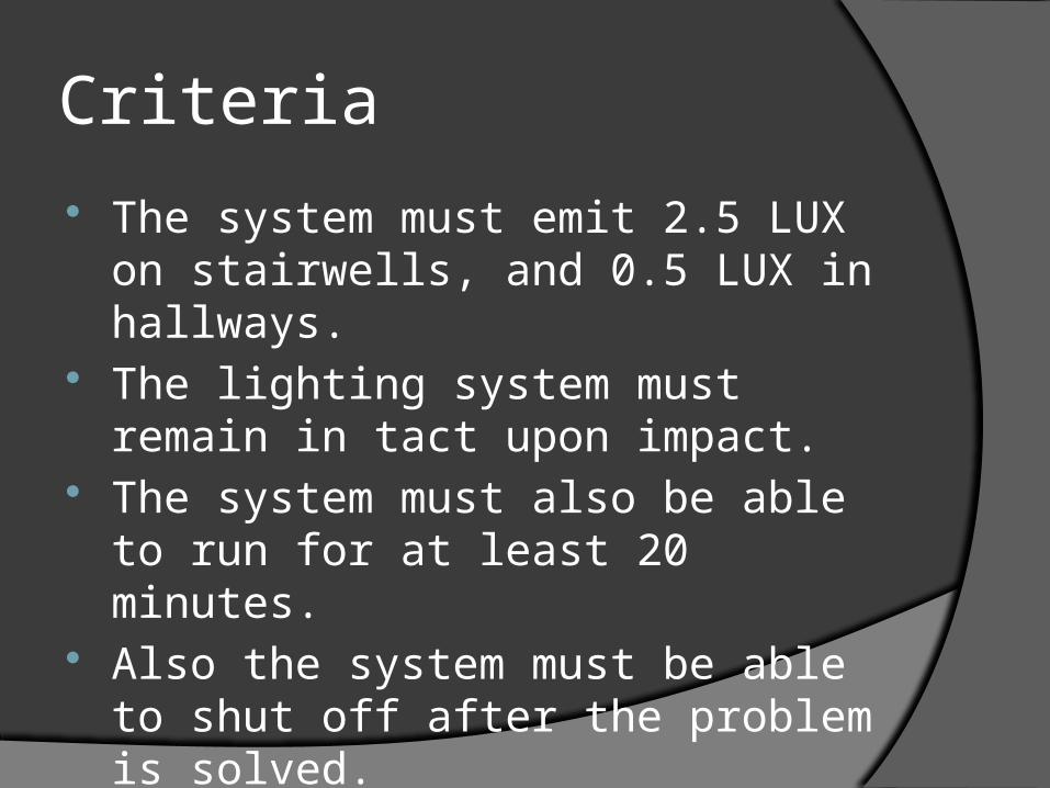
Criteria
The system must emit 2.5 LUX on stairwells, and 0.5 LUX in hallways.
The lighting system must remain in tact upon impact.
The system must also be able to run for at least 20 minutes.
Also the system must be able to shut off after the problem is solved.
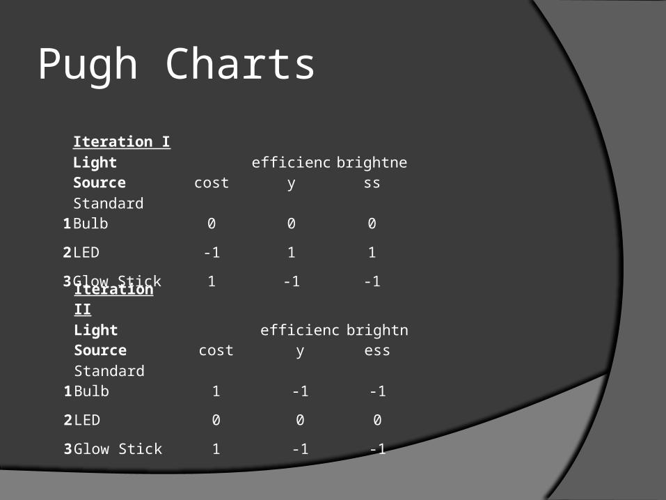
Pugh Charts
Iteration I
Light Source cost efficiency brightness
1Standard Bulb 0 0 0
2LED -1 1 1
3Glow Stick 1 -1 -1
Iteration II
Light Source cost efficiency brightness
1Standard Bulb 1 -1 -1
2LED 0 0 0
3Glow Stick 1 -1 -1
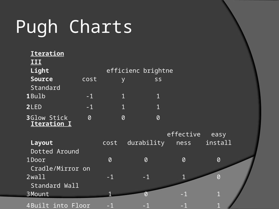
Pugh Charts Iteration III
Light Source cost efficiency brightness
1Standard Bulb -1 1 1
2LED -1 1 1
3Glow Stick 0 0 0
Iteration I
Layout cost durability effectiveness easy install
1Dotted Around Door 0 0 0 0
2Cradle/Mirror on wall -1 -1 1 0
3Standard Wall Mount 1 0 -1 1
4Built into Floor -1 -1 -1 1
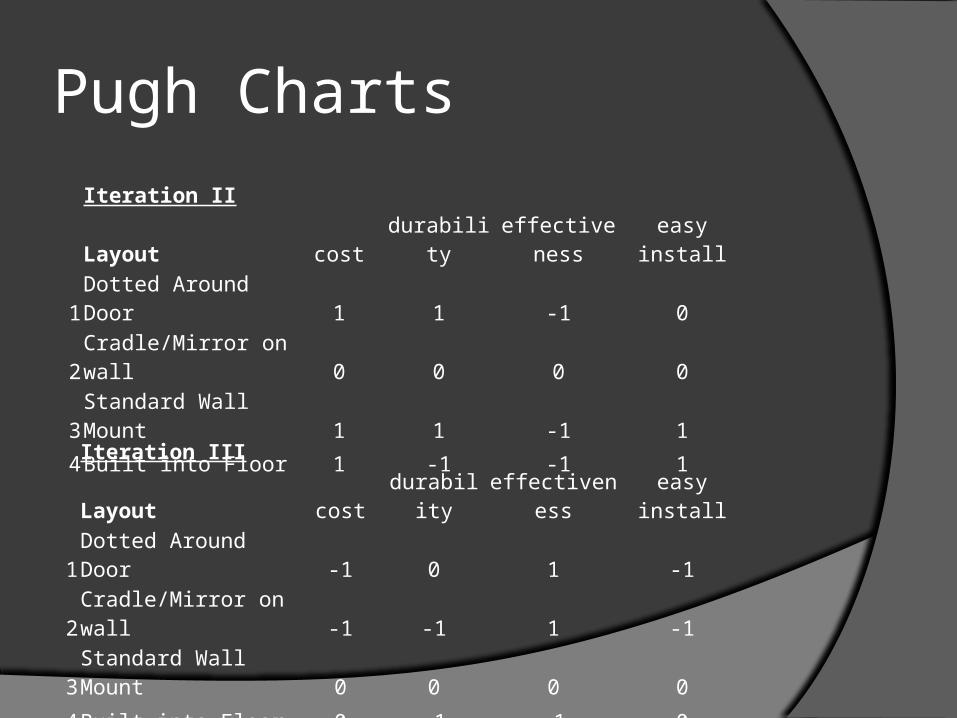
Pugh Charts
Iteration II
Layout cost durability effectiveness easy install
1Dotted Around Door 1 1 -1 0
2Cradle/Mirror on wall 0 0 0 0
3Standard Wall Mount 1 1 -1 1
4Built into Floor 1 -1 -1 1
Iteration III
Layout cost durability effectiveness easy install
1Dotted Around Door -1 0 1 -1
2Cradle/Mirror on wall -1 -1 1 -1
3Standard Wall Mount 0 0 0 0
4Built into Floor 0 -1 -1 0

Pugh Charts
Iteration IV
Layout cost durability effectiveness easy install
1Dotted Around Door -1 1 1 -1
2Cradle/Mirror on wall -1 1 1 -1
3Standard Wall Mount 0 1 1 0
4Built into Floor 0 0 0 0
Iteration I
Power Source cost efficiency size weight
1Solar Panel 0 0 0 0
2Li-ion Battery 1 1 1 1
3Rechargeable Li-ion 1 1 1 -1
4Lead Acid Battery 1 1 1 -1

Pugh ChartsIteration II
Power Source cost efficiency size weight
1Solar Panel -1 -1 -1 -1
2Li-ion Battery 0 0 0 0
3Rechargeable Li-ion -1 1 -1 -1
4Lead Acid Battery 1 -1 -1 -1
Iteration III
Power Source cost efficiency size weight
1Solar Panel -1 -1 -1 1
2Li-ion Battery 1 -1 1 1
3Rechargeable Li-Ion 0 0 0 0
4Lead Acid Battery 1 1 1 -1
Pugh Charts
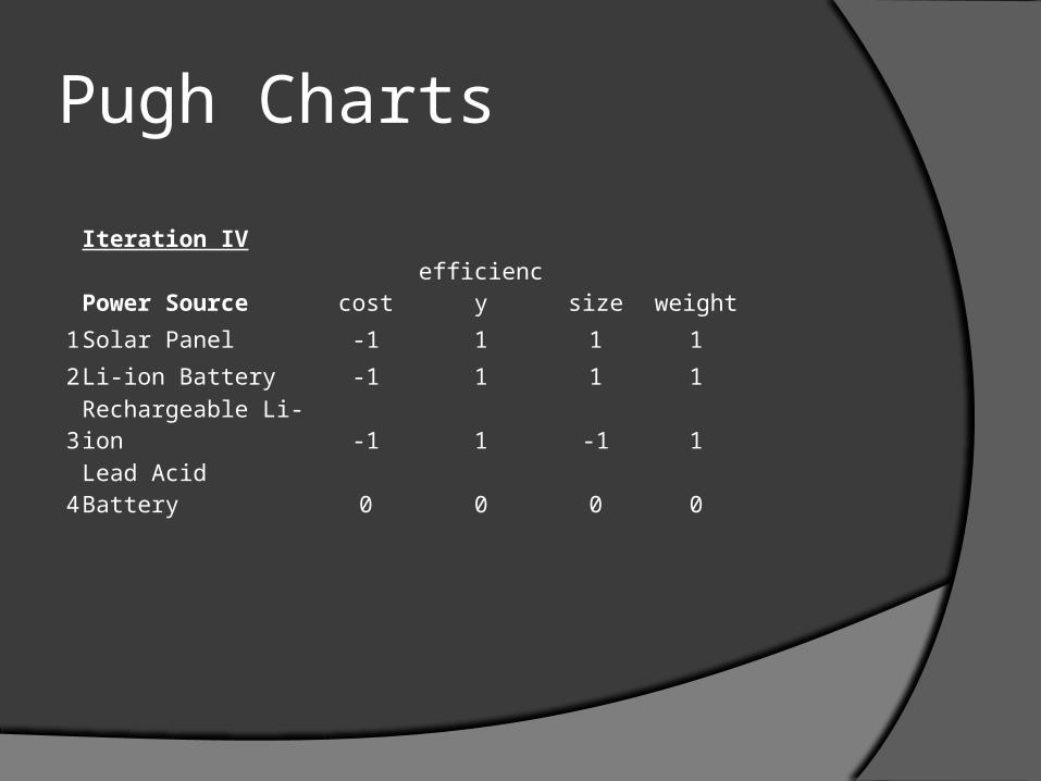
Iteration IV
Power Source cost efficiency size weight
1Solar Panel -1 1 1 1
2Li-ion Battery -1 1 1 1
3Rechargeable Li-ion -1 1 -1 1
4Lead Acid Battery 0 0 0 0
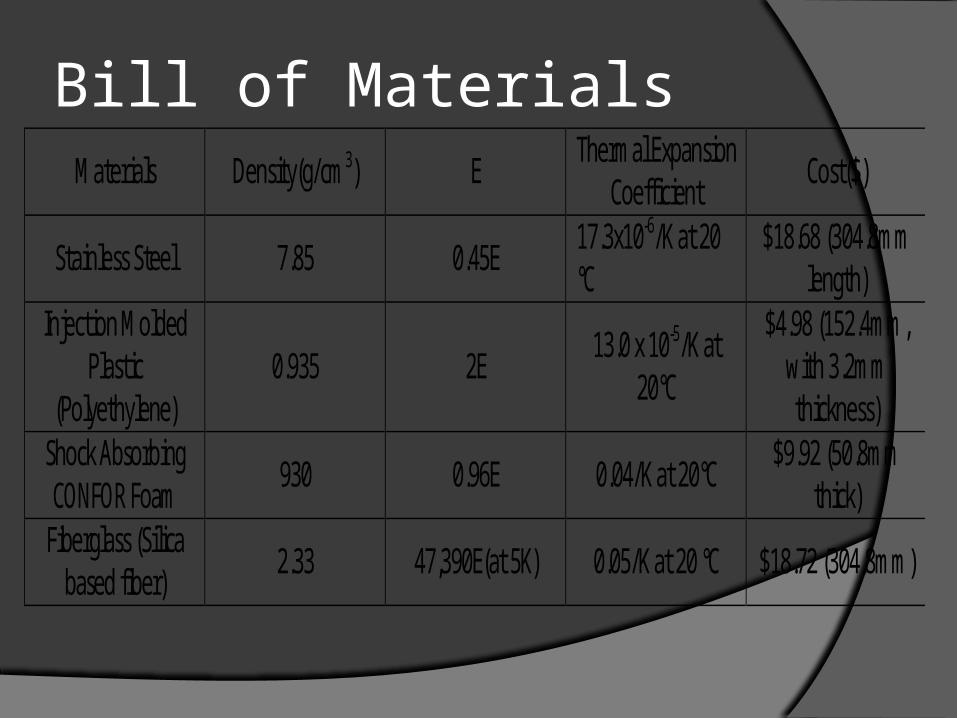
Bill of MaterialsMaterials Density(g/cm3) E Thermal Expansion
Coefficient Cost($)
Stainless Steel 7.85 0.45E 17.3x10⁻⁶/K at 20 °C
$18.68 (304.8mm length)
Injection Molded Plastic
(Polyethylene) 0.935 2E 13.0 x 10⁻⁵/K at
20°C
$4.98 (152.4mm, with 3.2mm thickness)
Shock Absorbing CONFOR Foam 930 0.96E 0.04/K at 20°C $9.92 (50.8mm
thick) Fiberglass (Silica
based fiber) 2.33 47,390E(at 5K) 0.05/K at 20 °C $18.72 (304.8mm)
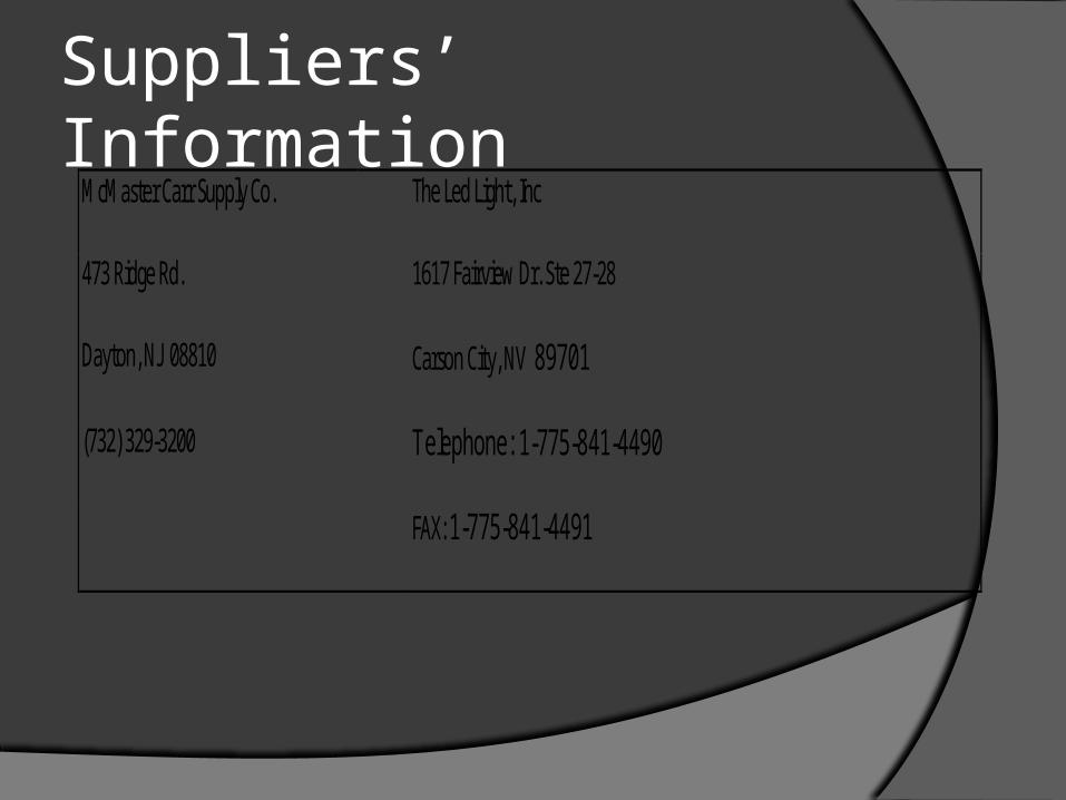
Suppliers’ InformationMcMaster Carr Supply Co. The Led Light, Inc
473 Ridge Rd. 1617 Fairview Dr. Ste 27-28
Dayton, NJ 08810 Carson City, NV 89701
(732) 329-3200 Telephone: 1-775-841-4490
FAX: 1-775-841-4491
Final Design Details When the conductor activates an emergency break, a signal
is sent to activate the lighting unit. The switch within the unit completes the circuit. The current is then drawn from Li-ion batteries connected in series. The batteries are placed within a three-layer compartment—outer layer of 1cm thick steel, 3mm of protective memory foam, and 3mm plastic. On the outside, they are covered by protective steel bars of 1cm thickness. The bars are removable so that the batteries can be replaced, as a typical Li-ion battery may discharge without usage over the period of five years. The current follows through insulated wires to the lighting units. Each lighting unit has a thick steel covering and steel bars protecting it. The reflector dish, which is made from highly reflective durable plastic, is further cushioned by memory foam. The reflector dish houses nine LED units.
Final Design Details Cont. Over the LED units, reflector mirrors are placed, which
reflect light emanating upwards from the LEDs back to the reflector dish, which in turn reflects the light back outside. The light is then further scattered by a concave lens. This achieves, very roughly, 70-130 degree visible beam (the lens diopter amount can be calibrated to suit the design—higher negative diopters will give a higher light beam angle, while positive diopters (making it a convex lens) would concentrate the beam is necessary), up from the 45 degrees that is provided by the LEDs utilized in this design. The bars themselves have a reflective paint painted on their underside so that any extra light that strikes them is reflected back into the reflector dish and then outside, conserving light. A manual shut off is accomplished by breaking a second switch within the circuit
Final Design Calculations The LED lights used in this design come from
www.theledlight.com online store. According to the website’s specification (PDF format) for 5mm 7000mcd 40-50 degree angle white LED, the LED operates at 3.2 V with 20mA current. A 4.5 V source per design is assumed.
POWER:According to www.ledcalc.com LED calculator for nine LEDs connected in parallel (each LED drawing 61 milliwatts of power), a 68 ohm resistor is necessary (each drawing 25 milliwatts of power) . The total power usage for this configuration of 9 LED, per single light unit, is then .774 (all power usages added together).
Final Design Calculations BATTERY CAPACITY:
According to http://www.techlib.com/reference/batteries.html , Li ion battery utilized in this design supply 1100 mAh of energy. According to www.ledcalc.com, the total usage for the 9 LED unit is 172.1mA. Multiplying this number by 5, which is the number of lighting units in the design, it is seen that 860 mA total will be drawn from the batteries. 1100 mAh/860 = 1.28 hours of lighting time, exceeding the 20 minute requirement by a large amount.
Final Design Calculations LIGHTING (LUMENS):
The 5mm LEDs utilized in this design are white, are 6000-7000mcd, and have a view angle of 40-50 degrees. Utilizing 6500 mcd, 45 degrees, these numbers can be converted to candelas. According to http://led.linear1.org/lumen.wiz , this degree-mcd combination yields 3.109 lumens per one LED. To convert to LUX, total area covered is needed.
AREA COVERED BY LIGHTING UNIT:Assuming 70 degree light dispersion using the mirror-reflector-lens combination used in the design, and applying trigonometry, then the circular area under the lighting unit will have a diameter of 1.4 meters. The total area, using the area formula, is then 6.16 m^s.
Final Design Calculations LIGHTING (LUX):
Using the 3.109 lumens figure derived above, the total LUX can be calculated. First, a total amount of lumens from 9 LEDs needs to be calculated. 3.109 x 9 =28.0 lumens. Tutal LUX can now be calculated 28.0 lumens / 6.16 m^2 = 4.54 LUX. Since the lighting coverage of the lighting unit is so large, an overlap from other units will also be present, and the LUX in certain areas will be even higher.
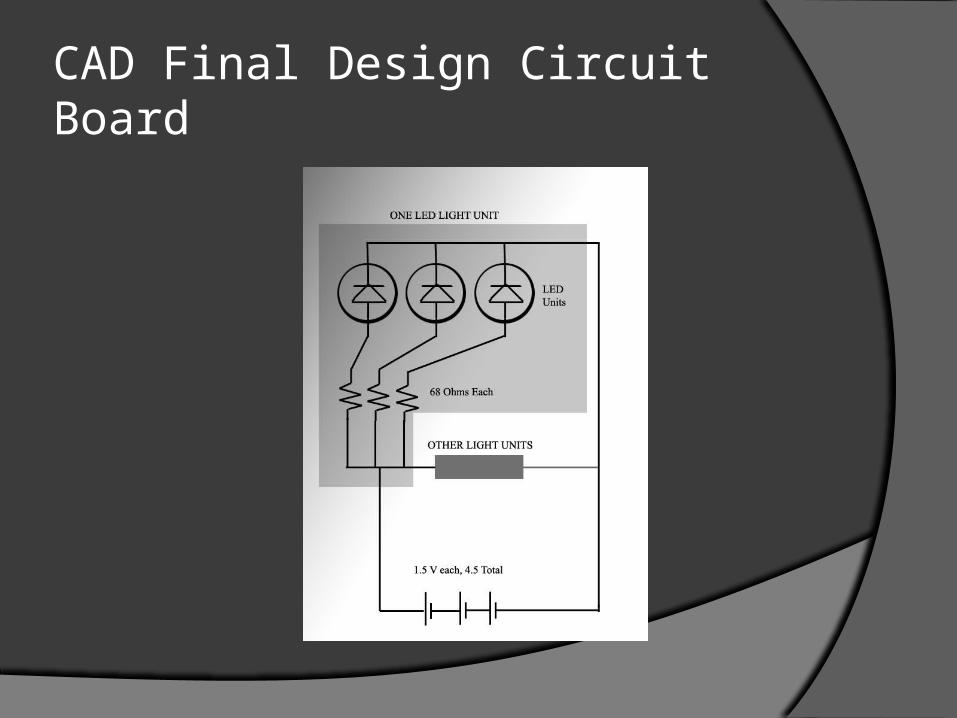
CAD Final Design Circuit Board
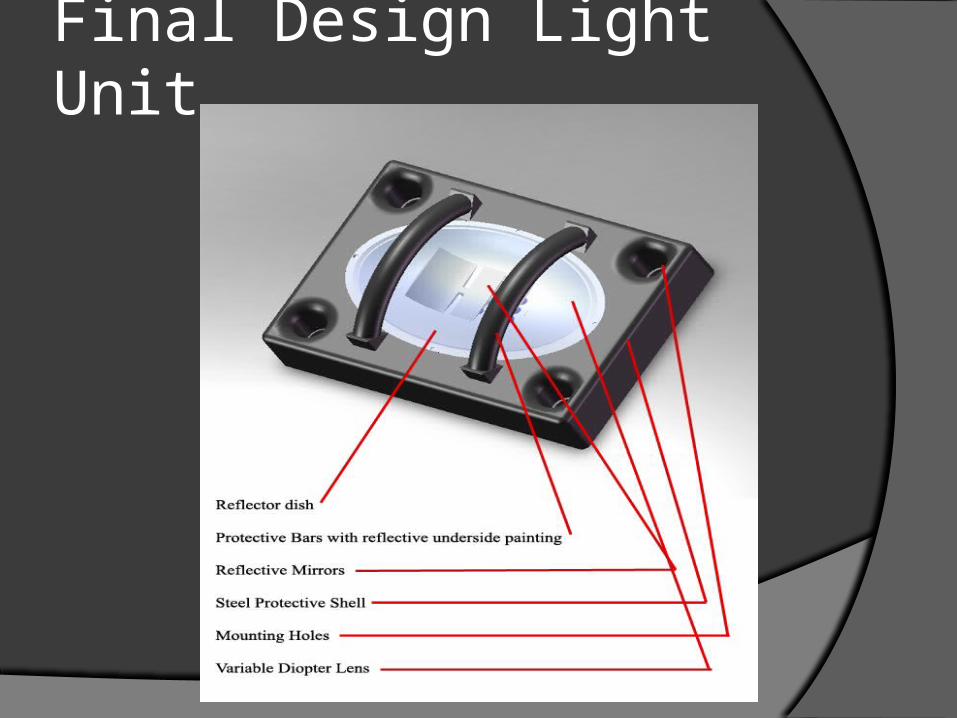
Final Design Light Unit
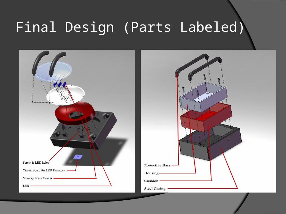
Final Design (Parts Labeled)
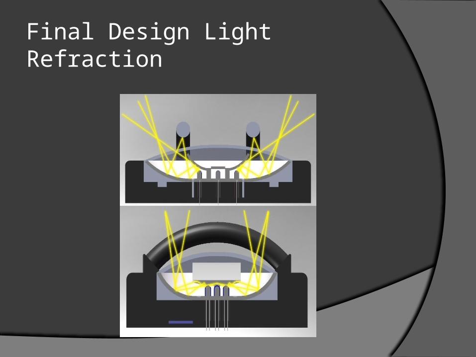
Final Design Light Refraction
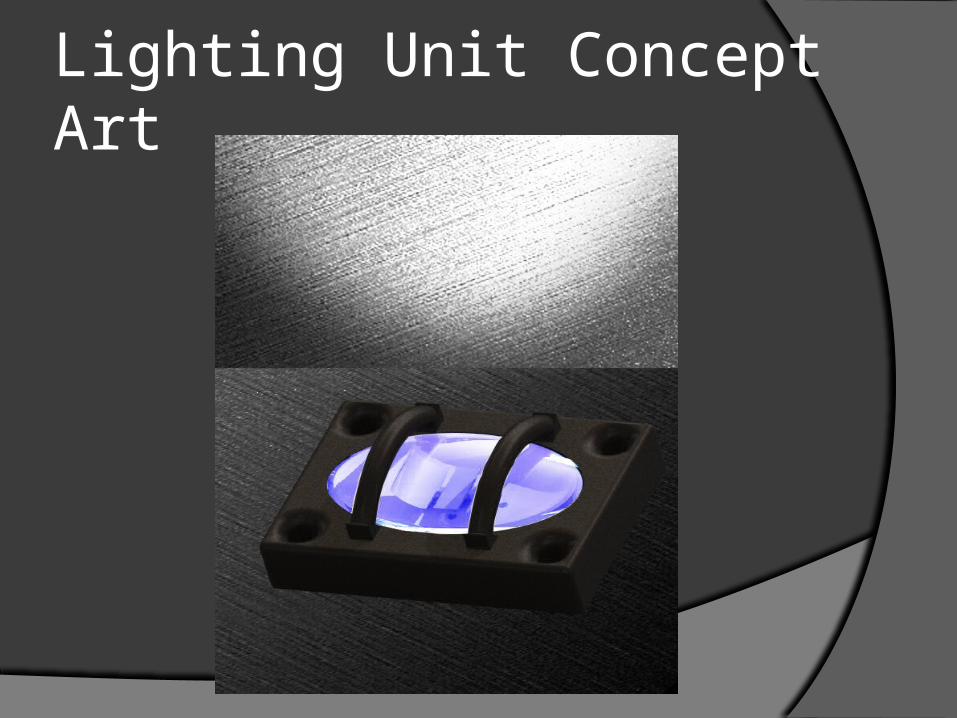
Lighting Unit Concept Art
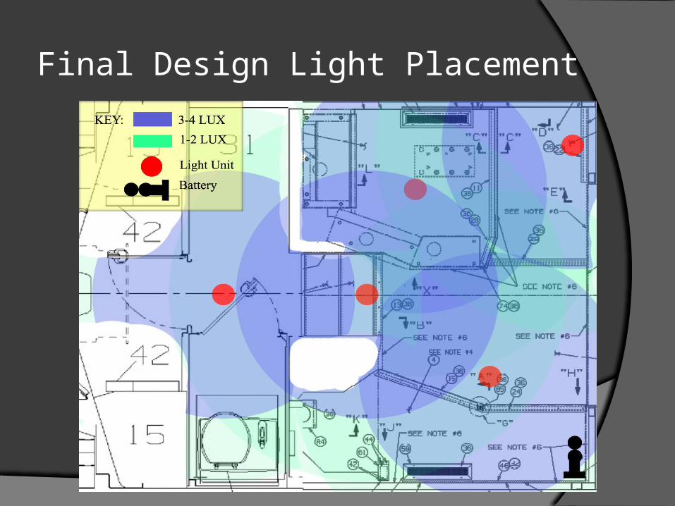
Final Design Light Placement
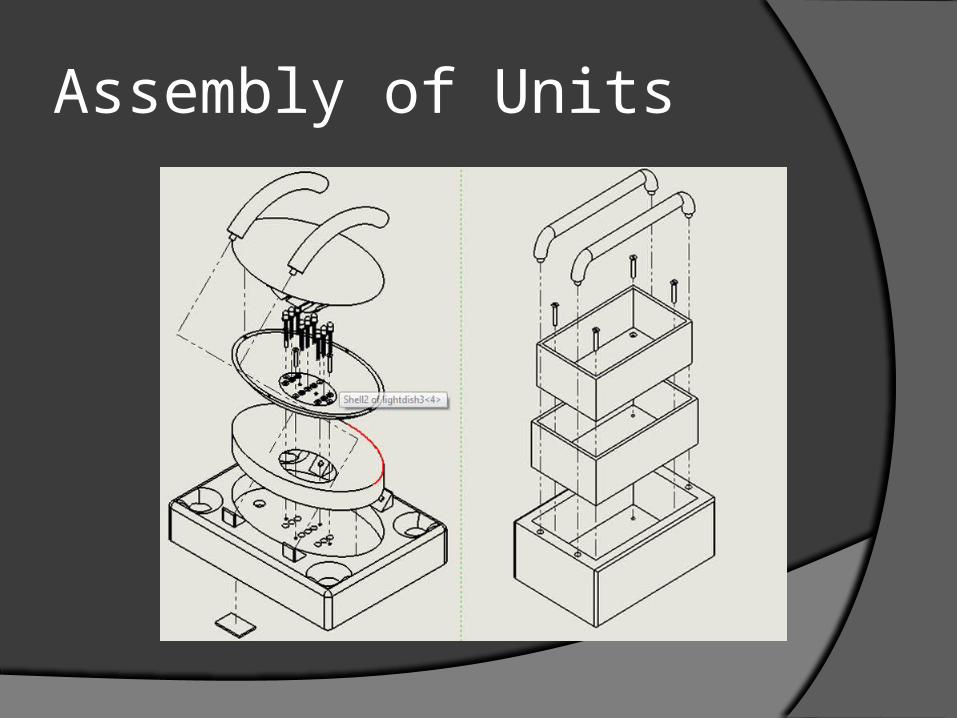
Assembly of Units
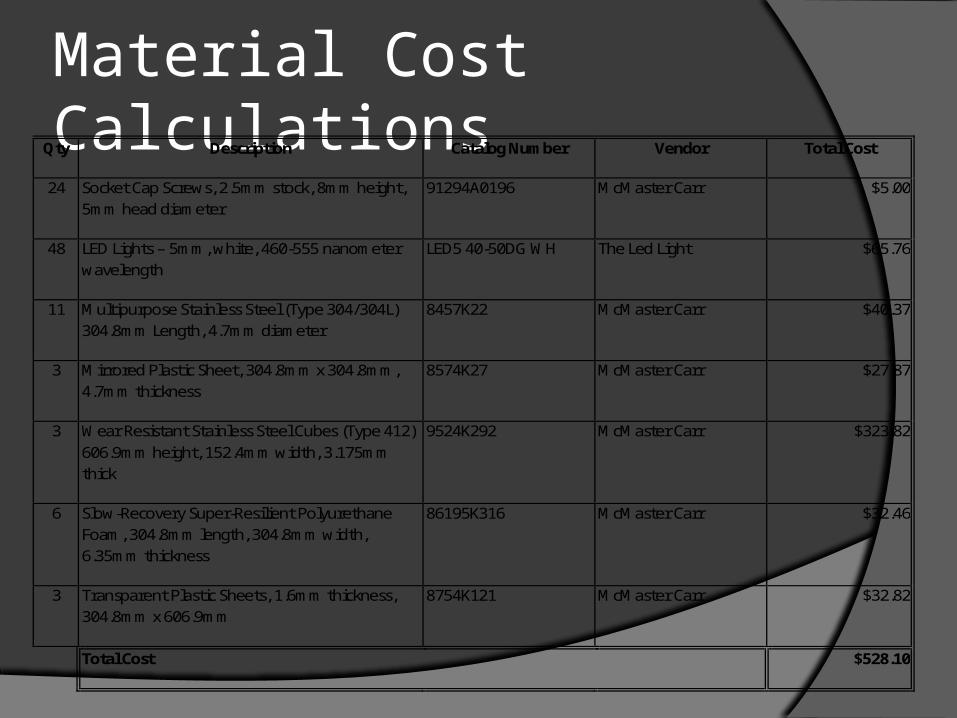
Material Cost CalculationsQty Description Catalog Number Vendor Total Cost
24 Socket Cap Screws, 2.5mm stock, 8mm height, 5mm head diameter
91294A0196 McMaster Carr $5.00
48 LED Lights – 5mm, white, 460-555 nanometer wavelength
LED5 40-50DG WH The Led Light $65.76
11 Multipurpose Stainless Steel (Type 304/304L) 304.8mm Length, 4.7mm diameter
8457K22 McMaster Carr $40.37
3 Mirrored Plastic Sheet, 304.8mm x 304.8mm, 4.7mm thickness
8574K27 McMaster Carr $27.87
3 Wear Resistant Stainless Steel Cubes (Type 412) 606.9mm height, 152.4mm width, 3.175mm thick
9524K292 McMaster Carr $323.82
6 Slow-Recovery Super-Resilient Polyurethane Foam, 304.8mm length, 304.8mm width, 6.35mm thickness
86195K316 McMaster Carr $32.46
3 Transparent Plastic Sheets, 1.6mm thickness, 304.8mm x 606.9mm
8754K121 McMaster Carr $32.82
Total Cost $528.10
Engineering Analysis
The total cost of the entire lighting system would be $851.92 which is a reasonable price. That includes 5 lighting units and the battery casing. Also the units themselves are not large and easily installed in the designated locations.
Concluding Remarks
After going through a thorough design process we feel that we came up with a quality product. As a group we conducted detailed background research, a customer needs assessment, a hierarchal customer needs list, and weights of importance for each main category of redesign. We then gathered ideas and used several techniques such as Pugh charts and a morphological chart to come up with the best overall design idea. After finalizing our design idea, we constructed several 3D models using SolidWorks.
Concluding Remarks These models show the assembly of the
individual parts as well as the overall mount design. We also built a prototype of our lighting system. Although the quantity and quality of the lights used in the prototype are not accurate to the actual product, it accurately represents how our system operates, and outlines all of the technologies used. Our system meets all requirements specified by GE and we believe it is the most efficient, and safest possible method of lighting for this locomotive.