Embed Size (px)
Citation preview

1
Sticks and Tissue No 64 – March 2012
If you can contribute any articles, wish to make your point of view known etc please send to or phone 01202
625825 [email protected]
The content does not follow any logical order or set out, it’s “as I put it in and receive”.
Thanks to Mark Venter back issues are available for download from
http://www.cmac.net.nz
Writings and opinions expressed are the opinion of the writer but not necessarily the compiler/publisher of
Sticks and Tissue.
Dave Platt launching his O/D "Tiara"

2
Last month’s unidentified engines from Brian Cox
Both the engines shown for identification last month are French.
The one on the left, with the gold head, is really cheating a bit. It’s 1.8 cc, and was made to order, by Jules
Maraget, in the early fifties. I think it’s probably a « one-off ».
However, the engine on the right is more interesting. It could well be the first Bosmorin diesel. It’s 3.5 cc
and is one of Marc Bosmorin’s known first series of diesels, made in the mid-forties... Except that this one is
different. It appears that work was started with the intention of producing a spark ignition engine and then,
during production, Mr. Bosmorin changed his mind and made a diesel, which would have been a very new
concept at the time. There is a bump (cam) on the rear face of the prop driver, and the head was originally
drilled for a spark plug, and then sleeved with a brass insert drilled for a compression screw (smaller
diameter than a plug). A few more of these engines were made, without the quirks mentioned above, and
also a smaller version of the same design, at 1.2 cc, but they’re all pretty rare...
Finally, I apologise for the quality of the photo. Unfortunately, I no longer possess the engines so I scanned
old paper photos. Both engines were traded with the late Miguel de Rancougne for an engine I wanted more
(the eternal problem), so they were probably sold at the famous Christie’s auction...
From Stephen Winkworth
MY ALL-TIME FAVOURITE - (Part 1)
Every model builder at one time or another finds that a certain aircraft becomes the one he flies most often
and has the most fun with. This is the model which sums up the whole pleasure of the hobby - the most
memories of calm summer evenings, of daring flights in pastures new, of close shaves, crashes survived and
repairs made to fly again.
It was a fine spring day in the 1980’s. I was wandering on the downhill slope of Epsom Downs, towards the
grandstand side, when a small group of free-flighters caught my attention. I forget what they were flying –
except for one model. It was simple, small and light, and its wings were mounted on wire struts, like an
indoor microfilm machine.
The engine was one of those very rare postwar miniatures – not an Allbon Bambi but an earlier
design, a Kemp or a Kalper, and the owner was running it slow and undercompressed, so that the model,
with its thin structure and taut see-through covering (Jap tissue? silk?) was just able to ghost along in a
gentle curve before coming to rest fifty yards away in the long grass. The whole machine trembled slightly,
dragonfly-style, as it flew.
He was one of those very careful, meticulous builders, and everything was extremely neat and clean. He
was making tiny adjustments to some kind of collet which allowed the trailing edge of the wing to move up
or down slightly on its wire strut.
To someone heartily weary of the current vogue for heavy, overpowered screamers made of
fibreglass and chunks of builders’ foam this was a thrilling sight. I was entranced – in love with this
delicate, totally different creation. Was there a plan, I asked? We exchanged addresses. ‘It’s called
‘Oomph’’ he said, and very generously promised to send me the details.
This is where I have to come across with some kind of chest-beating, eating of humble pie, abject apology,
expression of profound gratitude or possibly a hefty donation to a charity of choice, because, to my lasting
shame, I never contacted this kind person again. I think I lost his address – what other excuse could there
be? It nags my conscience to this day.
That plan changed the course of my model-building life.

3
‘Oomph’ was designed by a Frenchman – F. d’Huc Dressler, some time in 1948. I have an undated copy of
‘SAM Speaks 10’, which from internal evidence appears to have been issued in 1982 (why does a movement
with historical interests not remember that it too will be history one day? Dates are not everything but they
do help…). There is a simplified plan of ‘Oomph’ on page 3. Simplified – but it is such a marvellously
simple design in the first place. Oh, by the way, none of my present French friends seems to have heard of
the designer. M. Dressler’s name, with its curious hiccough-like prefix, is unknown to them, nor does it
figure in Jean Champenois’ La Grande Histoire des Petits Avions (ELP, Paris, 2004). However, exhaustive
researches reveal that a Frenchman of that name won third prize in the RAC International Aerobatics
Competition at Coventry in 1956, flying a Stampe 4VC biplane. So maybe, like Marcus Norman, he went
on from model flying to full-size aerobatics. (Marcus, and his dad P.E.Norman, used to fly single-channel
ducted fans on Epsom Downs in the 1950’s. Tragically, Marcus died when his Stampe folded its wings and
crashed in 1987.)
There had recently appeared on the market various very small radio units, and it occurred to me that one of
these might just be made to fit ‘Oomph’. I ordered a ‘Century Systems’ unit, which featured a receiver
about the size of a couple of lumps of sugar, but trailing leads in all directions, and four of the smallest
servos I had ever seen – around one inch square and less than half an inch thick, and weighing a little over
half an ounce. The battery recommended was a stack of four 110mAh button cells, and there was an
ingenious jack-plug system to obviate the need for a heavy switch. Using only two servos, for rudder and
elevator, I worked out that the whole system need not weigh more than around two and a tad ounces. Not
bad for 1984. One of the main reasons Century were able to achieve this light weight was a very low current

4
drain. The servos were pretty feeble in consequence (in fact, when first delivered, before being properly
‘run in’, they had to be given a bit of a push to overcome their own internal friction!) It did mean, as I later
discovered, that the 110mAh button cells would happily last for at least ten flights.
Despite these advances in miniaturization, the radio was clearly not going to fit inside the slim square box
fuselage shown on the plan. I ended up enlarging the box to an inch and a half square and the wing to 7 x 24
inches, with appropriate increases elsewhere. A subsequent rebuild of the wing, after the silk covering had
become brittle and the wood oil-soaked, added another three inches to the span – quite a bit larger than the
original, with its six by nineteen inch wing. I also decided, in a gadget-minded moment, that it might be fun
to try three fins, as in O.F.W.Fisher’s ‘Apex’, linking the rudders by means of a transverse bar of 1/8 dowel,
suitably pierced for locator pins on all three rudders. The concept was now moving some distance from M.
Dressler’;s original, so I renamed it ‘Ooomph’ – with three ‘o’s for the three fins. Later models based on
‘Oomph’ were ‘Oof’ (a chuck glider), ‘Emf’ (electric powered), ‘Pimf’(lightweight electric), ‘Sploosh’ (a
floatplane), and ‘Oops’ (a first model built by a friend’s son).
All these derivatives, like Ooomph itself, employed the same structural principles. The two tailplane
halves plugged into wires projecting from the rear of the fuselage, and a Bowden-style undercarriage, held
by a light spring, plugged into transverse brass tubes. The wing was in two halves as well, and plugged into
the inverted ‘Y’ shaped wire ‘cabane’, which also fitted into tubes bound to the top of the fuselage. The
angle of the wire ends determined the dihedral. Later experience showed how useful this system was in
absorbing crash loadings; moreover it enabled the whole thing to fit neatly into a small plywood valise,
which was also made to accommodate a pint can of diesel. (The skis were a later idea, and were kept in the
box mainly for bragging points. I think I only used them twice.)
Don’t forget coming up
Easter Weekend Middle Wallop – FF, RC, CL
15 April Control Line day at Wimborne Club – Cashmoor site Nr Gussage St Andrew between
Salisbury and Blandford Forum.
6 May Middle Wallop – FF, RC, CL
13 May RC Vintage at Wimborne Club
5
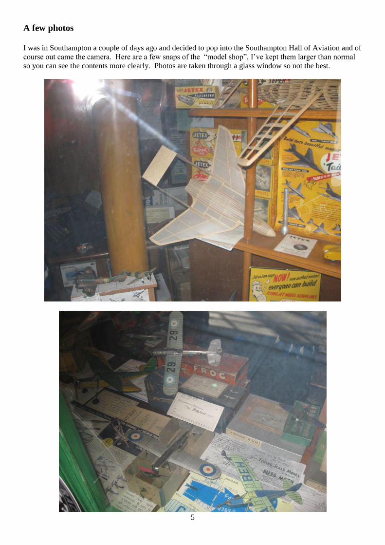
A few photos
I was in Southampton a couple of days ago and decided to pop into the Southampton Hall of Aviation and of
course out came the camera. Here are a few snaps of the “model shop”, I’ve kept them larger than normal
so you can see the contents more clearly. Photos are taken through a glass window so not the best.

6

7

8
From David Turner
Here's a bit of video, showing some vintage flying.
There's a Glenelg and an Alert, being flown by my friend Dave Bell. He also built the models.
Pete Oyston is flying a Shereshaw Commodore ... builder Jack Lea, from Coventry-way, I think.
Dave also has Jack Lea's Fiske-Hanley and RC1.
It's not great video, but it might be useful as a filler for your publication.
http://www.youtube.com/watch?v=EpRYvH_34RE&list=UU4HLk42VM0CCjglQ2KPcYdA&index=1&fea
ture=plc
You might also care to see these short clips of my Ivory Girl being launched. It's a scaled version of the
Gosling' design "Ivory Gull"... 116" span, nylon and dope covering.
http://www.youtube.com/watch?v=sUx_6lOO-
Dc&list=UU4HLk42VM0CCjglQ2KPcYdA&index=2&feature=plcp
http://www.youtube.com/watch?v=hZlqu2ehrWA&list=UU4HLk42VM0CCjglQ2KPcYdA&index=3&featu
re=plcp
http://www.youtube.com/watch?v=p0Gm_4hvNMI&list=UU4HLk42VM0CCjglQ2KPcYdA&index=4&fea
ture=plcp
9
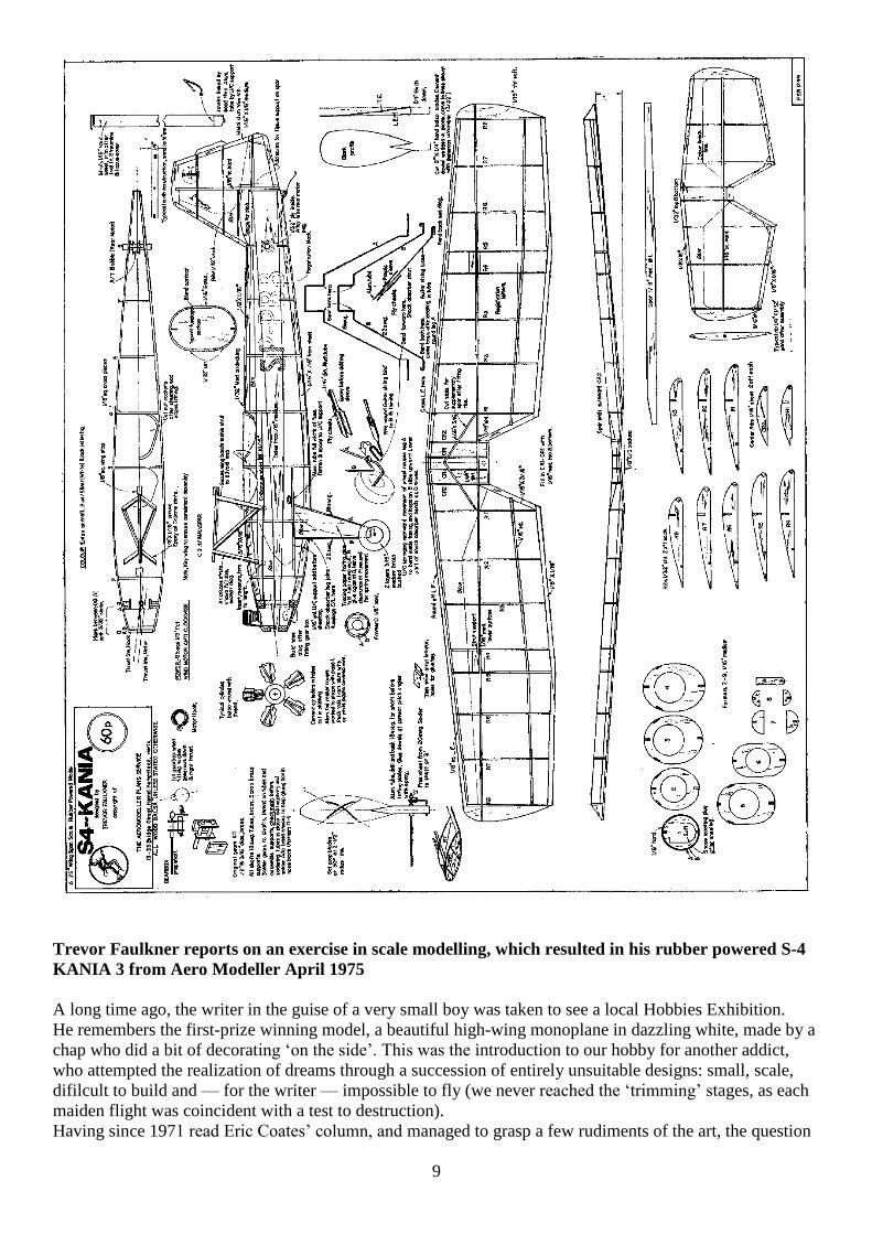
Trevor Faulkner reports on an exercise in scale modelling, which resulted in his rubber powered S-4
KANIA 3 from Aero Modeller April 1975
A long time ago, the writer in the guise of a very small boy was taken to see a local Hobbies Exhibition.
He remembers the first-prize winning model, a beautiful high-wing monoplane in dazzling white, made by a
chap who did a bit of decorating ‘on the side’. This was the introduction to our hobby for another addict,
who attempted the realization of dreams through a succession of entirely unsuitable designs: small, scale,
difilcult to build and — for the writer — impossible to fly (we never reached the ‘trimming’ stages, as each
maiden flight was coincident with a test to destruction).
Having since 1971 read Eric Coates’ column, and managed to grasp a few rudiments of the art, the question

10
of making a flying replica really work
began to niggle away at my self-esteem. As
I usually reckon that it’s been a rough
session if we have to replace a wing-band
on the 13-footer, it did appear that the
thrills of youth had vanished into the mists
of time, so what could be more appropriate
than a spot of self-mortification (sorry,
rubber-powered free-flight scale)?
Well, I started chicken, looking for high-
wing, swept-back prototypes with
reasonable tall areas and moment arms. The Polish Kania didn’t seem to have caught anyone’s eye, and so
the AeroModeller scale drawing No. 2927, price 27p, was purchased. After a bit of debate between ambition
and common sense, it was decided that:
1. The scale would be a multiple of the 1/16th scale drawing.
2. A reasonably tough construction would be used.
3. Motor run would have a fair amount of ‘punch’ to avoid the prolonged glide type of flight to which
Mr. Coates refers.
4. A step-up gear would be used to carry the rubber without tensioning turns, and allow a smaller blade
prop. to be fitted.
5. Wings to be detachable.
6. Undercarriage to be sprung.
7. Model would be made to fly (if at all possible) before detail finishing.
8. Tailplane and rudder would be variable for trim, then secured.
9. The entire project was aimed at the production of a flying model.
10. The model would not use exotic materials (i.e. Jap. tissue, 11in. square
rubber or expensive bought-in parts), nor would finishes other than
those applied by brush be used.
Eventually, the drawing was redrawn twice full size, giving a span of just over
2ft. Consideration of the
fuselage sections showed a close approximation to circular sections, or semi-
circular linked by straight
parallel sides. The draughting of the fuselage was in fact very easy, as the
width in plan of the
AeroModeller
drawing became the finished
profile section radius (x 2, remember) at the corresponding
point.
Bulkheads were drawn directly onto balsa by
measurement, allowing for 1/16in. sheeting all round.
Stringer slots were filed for accuracy on the top and
bottom, and the rubber clearance spaces were cut and
sanded by eye. The gearbox dictated that the nose-block
should be rather more than the bushed-button type, and the radial engine is, in fact, the nose block.
As to the gearbox, a pair of old clock gears was found to give a 4 : 1 ratio, although plastic gears were
considered. A clockwork toy would probably yield a suitable pair, and provided the smaller gear is about
1/8 in, thick and a good tooth profile match is made, the larger pinion may be quite thin. Gears may have to
be removed from their shafts, and as most are press fits the job can be done by supporting the gear on a
partially open vice, and gently tapping the shaft. The resulting hole is then bushed to size with sections of
brass tubes, soldered in place.
The propeller was designed to be replaced easily for development work. Two simple laminated props. were
first made, only the larger being used, this in turn being modified quite atrociously before being replaced by
a slicker-looking job!

11
It can be stated that the prop. and gearbox are the only parts to be made with any amount of painstaking
work; the rest of the model was put together rapidly, and could be bettered by a very average modeller with
no trouble.
Construction
Gearbox: Ensure bearing tubes are parallel and that pinions mesh easily before soldering or gluing solid.
Dope any wood in vicinity of the box to avoid oil-seepage.
Propeller: Carve two blades from hard quarter grain, insert hardwood dowels into roots, glue with epoxy.
Drili alloy tube to take prop. bearing tube, gluing blades in position.
Fuselage: Cut sides from medium balsa, formers from similar stock. Mark formers with position of sides,
and sides with position of formers. Assemble sides and formers, then when dry, fit top and bottom stringers
— everything must be square. Make paper patterns of rear sheeting, upper and lower, aft of the cockpits. Cut
wood slightly oversize from soft stock, damp it and curve to shape over the formers, holding it in place with
tape or bandage until dry; then glue the sheets in place. Complete the remaining sheeting jobs in the same
way. The basic shell formed, mark out positions for cabane struts, wing strut and landing gear pick-up
points, adding reinforcement where required by cutting through the shell and inserting the members shown.
The nose-block is planked with 3/32 in. hard, tack-cemented to the front former and sanded to shape.
Give the fuselage a coat of 70/30 dope/thinners, sand smooth, then cover with sections of white lightweight
Modelspan tissue, laying the paper on wet and doping with a 50/50 mix immediately. When dry, sand lightly
and cover areas to be blue with suitable pieces of Modelspan in the same way (wet doped). Cut out cockpits
when dry, adding string padding for finish. A coat of very thin dope removes ‘blush’ when all is dry.
Wing: Entirely conventional, but note that the spar depth tapers to tip, and does not sweep back. Original
was covered in damp tissue which, when dry, was doped, and the blue trim added as for the fuselage.
Tailplane and Rudder/Fin: Rectangular ribs are pierced for central spars, slotted for LE. and T.E., assembled
and sanded to profile when dry. Cover (white tissue), dope, then decorate as for wing.
Landing Gear: Both main struts have a central loop which helps in holding them at the correct angle to the
fuselage. The bend at the point of emergence from the fuselage side is made fully in one leg only; the other
is just kinked to assist bending when the wire is passed through. The ioop at the lower section of the front
strut allows good backward movement, also compensating for slight inaccuracies in bending! Manipulate the
rear struts into these loops before gluing legs in place. The oleo legs use wire-wound guitar strings, cable
insulation, alloy tube and 0.8mm ply packing. The wheels are from two cross-grained balsa discs, glued
together, with a 2 in. section of brass tube epoxied in place as a hub. A matching piece of wire passed into
the tube allows it to be gripped firmly in the chuck of an electric drill without kinking. Drill is vice-held, and
the ‘turning’ done with sandpaper scraps folded around suitable supports. The tube is useful during painting
processes, and is trimmed to length when wheels are completed, forming the bush specified.
Flying
This began with the dreaded ‘extended glides’ until I realised that the 4 : 1 gearing really would get used
only if I forgot straight-drive thinking. I also lost count of turns — silly, isn’t it — and broke all strands at
once (Dunlop has this habit) which removed a few formers.
Regrouping the rubber into six loops of 1/8in. flat (instead of the previous four) seemed better, with a little
more height, but still descent was powered, and half-turns remained . . . and then the real goof. The anti-
clockwise winding direction loosened the hook in the drill chuck, and on three-quarters turns (stretch
wound) this vicious lump of steel really had fun going half-way down the fuselage! This was the point
where I felt it was time to quit, but fortunately persevered. Repairs were quick and rough, confined entirely
to the sheeted shell, and the following very windy day I was able to work towards a better pattern.
By now, it was obvious that launching was much more critical than on a higher-powered job; a straight
launch often led to a couple of power stalls with a cruise at about 10ft., whereas a banked launch (to the
right) kept the nose down to avoid this, and let the spiral climb ‘come in’ after the first circle.
The pattern I chose to fly was the conventional right/right normally used by rubber fliers — this was not
because the model could not be trimmed for a left-hand circle but in response to my built-in assumption that
right/right is best for rubber (the noseblock had been skewed from the outset ‘down and right’).
The pattern was not satisfactory, though, and 18-second flights were nowhere near passable, so the prop.
Was lengthened by splicing in tip sections to the T.E. The next session was infinitely better with eight loops
to cope with the bigger prop., the model turned in steady 23—25 second flights without really trying on 60
per cent power, and getting to about 25ft.

12
Even a take-off from a pebbled tarmac surface was 100 per cent successful, and so it was decided to carve
the prop. shown, reducing hub depth by half and trying to get the
prop/power combination correct. The dihedral was increased
1/4in. to improve on the launching problem.
At the same time, a little more detail was added, the radial engine
being mocked up, the undercarriage struts
faired in with tracing paper, windscreens fitted and a spot of blue
enamel added to ‘beef-up’ the rather washed-out tissue trim on
the fuselage. Registration letters were applied (not quite
authentic, but I was plumb out of ‘P’s’ and ‘B’s’!).
The cylinder heads were modded to have alloy rocker box covers
formed with a soft pencil point, worked inside a cream carton foil cap to stretch the foil to shape. The fuel
tank cover was made in the same way (a version of the ‘repoussé’ technique, really). Exhausts and silencers
were omitted, as it was felt that the effects of the new prop. and
radial engine would be enough to assess in the next series of flights.
The temptation to go on adding detail to a model once it begins to
shape up must be quite addictive, and only a firm resolve to honour
intentions No. 9 prevented the Christmas tree look.
The next series of flights began to repay the effort and thought
expended. By this time, I was getting used to the steep glide with the
prop. freewheeling. . . very different from the Open Rubber or
Wakefield glides one begins to regard as a norm. Careful
adjustments of thrust-line settings (never mentioned in the articles
I’d read as a boy!) produced a reliable right-hand circle; launch technique became easier as the angle of bank
to get ‘into’ the turn could be forgotten. A slight enlargement of the tail areas improved longitudinal control,
and the rudder trim tab was adjusted to give just enough right turn at the stage in the power when the right
thrust was becoming less effective. (Previously, the model had a fitful transition; if a stall began, it would
sometimes lurch into a left-hand spiral down to ground level; never vicious enough to cause damage, as I
flew over long rough grass for all trimming flights.)
The tailplane angle having been set, it was then cemented in
position; the thrust-settings were ply-faced
for permanence, and some solid flying was put in. This text, in
fact, is being completed on the cessation of a
splendid afternoon’s flying. Having gone out basically for some
slope-soaring, I thought it might be good
insurance to take the Kania along. Hardly a breath of wind, a
brilliant sky, and lots of tame R/C types all
waiting to be taught to hold a rubber model for stretch-winding!
A whole succession of 35—40 second flights, a demonstration take-off from the highway, and that smug
feeling we all have when our model’s airborne, and the ‘opposition’s’ grounded . . . believe me, that’s real
therapy: and we’d laid the old spectre of the small non-flying scale model at last!
I hope this account may encourage some readers to try this most intriguing sport of designing and flying —
you don’t need much more than an AeroModeller scale drawing as a start. The scope for experiment
remains; for instance, I cannot believe the prop/power
combination is the ultimate, nor that it would be
impossible to fly with exact scale surfaces on calm
days. Nor has the idea of a feathering free-wheeler
been abandoned . . . nor the possible use of the Go.532
wing section! The robust aspects of the model (happily
flying with only 30 per cent formers remaining)
encourage me to experiment, and the quick-building
features of small models makes this a possibility in
terms of time.

13
From George Stringwell
I've just completed and flown my electric R/C adaptation of the Frog Witch II rubber model, and am highly
delighted with it. It has come in at 5.1/2 ounces (155 grams); I had hoped to get closer to 5 ounces, but
finished up using a heavier dual conversion receiver. Power is a little 40 watt out runner brushless driving a
7" x 3" prop from a 300 2S (7.4 volt) lipo. The performance is an absolute delight, both as a park flyer and a
mini-thermal soaring machine. Control response is excellent, totally predictable, and with the CG at 63%,
almost in the F/F position stability is excellent and it can be trimmed to climb up in gentle circles, hands off.
It delivers great enjoyment for the relatively small building effort and cost involved and I am very happy I
decided to build it.
Some pictures attached, as ever the flying ones were taken by my wife and faithful photographer Ali, who
found the experience quite relaxing after chasing the high speed Mamba round the sky!

14
George’s Mamba
I thought you might like to know that my double size Frog Mamba you showed photos of in the last issue
has now passed it's flying tests with distinction. As I expected, on a 3S lipo (150 watts plus per pound) it is
blindingly fast and extremely aerobatic, not at all your average vintage model, only needs half throttle most
of the time, in fact I think I shall fly it on 2S mainly, at least until my gammy knee is fixed as it is so quick I
kept nearly falling over trying to keep up with it! My wife, Ali, who does my flying photos, did well to
catch it in frame, although on the first, launch, shot, the acceleration almost beat her. Three photos attached.
As you will see from the sky, spring arrived in the Haute Vienne last week. 20 degrees when, just ten days
earlier it had been down to minus 18! Crazy weather, but a great few days for flying!
Hi James from George Stringwell
Not wishing to turn S&T into a want ad magazine, but only if you think it would be appropriate could you
include the following plea:
"I moved to France in 2006 just at the start of the 2.4 gig revolution, and took all my faithful and endlessly
reliable 35 MHz gear with me. The French FFAM, having lost over half of their 40 MHz spectrum,
legalised two channels of 35 MHz, 60 and 61 with (quote) "more to follow" - we are still waiting for the
other channels! Not to worry, I have two lovely Futaba FF8 Txs with CAMPACS giving me 56 memories
plus over 25 receivers, mainly Futaba and Hitec, both single and dual conversion, and some Microns, they
all work perfectly and I am in no hurry to dump them in favour of 2.4 gig, especially as some 2.4 gig Txs
have too high an output to be legal in France. The problem is crystals. As a former thermal soarer I have an
extensive collection of crystals - but only two on most frequencies. I have a big and steadily growing
collection of electric models, vintage, scale, soaring and aerobatic, currently numbering sixteen, which I like
to keep in ready to fly order without having to fish around inside for the Rx to change crystals - but I have
only managed to gather together one transmitter and 9 receiver crystals on channel 61 and have none at all
on channel 60. Has anyone out there some 35 MHz crystals which they are willing to part with?
Specifically I am looking for:

15
1. A channel 61 Futaba Tx crystal As many Futaba/Hitec compatible channel 61 receiver crystals, both
single and dual conversion as I can find.
OR, failing the above:
2. A channel 60 Futaba Tx crystal A number of Futaba/Hitec compatible channel 60 receiver crystals,
both single and dual conversion.
OR some combination of 1 and 2!
I am happy to either buy these at the going rate or, if preferred, swap them for other frequencies (paying all
postage costs of course), apart from channel 60 I have Tx and Rx crystals (Rx ones mostly single conversion
but some dual conversion) for pretty much all of the even number channels from 62 upwards, mostly two
per channel, but some with more. If anyone can help, please email me at
Engine Test Webra 2.46 cc. Model Aircraft February 1953
Through the co-operation of the Berlin firm, Modell-Technik,
we have been able to conduct a test on Germany’s most popular
model aircraft engine, the 2.46 c.c. Webra.
This is a diesel and follows the well-known “International”
class formula of a shaft-valve, annular porting and light weight.
The Webra is actually one of the lightest 2.5 c.c. diesels yet
seen and, in consequence, has one of the highest power-to-
weight ratios realised among F.A.I. Class “ I “ diesels.
Brief details of the Webra’s history and of its place in German
modelling activities have already : been given in MODEL
AIRCRAFT (“ Accent on Power” —December, 1952) and this
report will, therefore, concentrate mainly on the engine’s actual
performance and behaviour. Suffice it to say that the Webra is a
neat and functional design with a general standard of casting
and machining well up to expected European standards. For the
benefit of those who immediately look to the performance
curves to assess the merits of engines featured in this series, let it be said that, due to reasons given in the
following paragraphs, our test
unit did not quite reach the performance which we feel that this design is capable of delivering. Therefore,
too much should not be assumed from the fact that the Webra may only appear as of “ average “
performance according to the figures obtained from this single test example
Specification
Type : Single-cylinder, air-cooled, two-cycle, compression-ignition. Induction via shaft-type rotary-valve
with sub-piston supplementary air induction. Annular type exhaust and transfer porting with conical crown
piston.
Swept volume : 2.463 c.c. (.1503 cu. in.).
Bore : 14 min. (.5512 in.) Stroke,: 16 mm. (.6299 in.).
Compression-ratio : variable.
Stroke/Bore ratio : 1.143 : 1.
Weight : 3.6 oz.
General structural data : Pressure die-cast aluminium alloy crankcase with screw-
in rear cover and integral main bearing housing. Hardened steel cylinder-liner,
threaded into crankcase. Machined aluminium alloy cylinder-barrel, anodised and
threaded on to cylinder-liner. Hardened steel crankshaft with full disc type web.
Cast-iron, lapped piston with gudgeon-pin pressed in. Cast-iron contra-piston.
Spray-bar type needle-valve with brass body. Dural prop. drive collet fitted on

16
crankshaft taper. 3-point bulkhead type mounting
lugs.
Test Engine Data
Running time logged prior to test: 1 hour. Fuel used: Mercury No. 8 (castor base).
Performance
In general, all engines to this popular formula, i.e., 2.5 c.c., annular port, shaft valve, respond to much the
same starting technique and the Webra is no exception. It starts very easily, hot or cold, and is not at all
critical. With the needle-valve set in the running position—1 ¼ turns open on the test engine— the Webra
will start after a couple of choked flicks. When starting up from cold for the first time, about five choked
flicks were used. At no time was it found necessary to prime through the exhaust ports, although this
method can, of course, be used if preferred.
It was not stated how long the test unit had been run before reaching our hands and a check run-in period of
one hour was given before the test. From this, the engine seemed to be reasonably well run-in and ready for
high-speed runs: it held even speeds under load and power loss when hot was only very slight.
However, our test engine did have one unfortunate fault. This appeared to be due to the cylinder not having
been lapped out quite parallel, resulting in a tendency for the piston to tighten towards top-dead-centre and
in an extremely tight contra-piston. This complicated the tests somewhat. As expected, the added frictional
loss due to tightness at the top of the stroke resulted in a lower torque being developed than that indicated by
the makers’ performance figures, although, surprisingly, torque was still
good and would therefore indicate that the Webra is actually capable of
above average performance in this respect. We would, in consequence,
judge the makers’ claim of .22/.23 b.h.p. at 11,000/12,000r.p.m. to be a
fair one.
Due to the tightness of the contra-piston, it was necessary, when altering
compression to suit load, to make each readjustment towards the critical
setting by increasing compression only, and not by backing off from
excess compression. This difficulty has, of course, been experienced with
other engines and was disclosed in a recent test of a British 1/2 c.c. diesel.
Once the engine was running, the contra-piston would not return when the
compression- screw was released and, when hot, it also became difficult to
increase compression.
In all fairness to the manufacturers of the Webra, however, we must emphasise that the difficulty we
encountered with our test unit is not likely to be generally experienced. We mention it because it is the
purpose of these reports to give a full and accurate account of our findings and because it explains the
fact that the performance obtained, though still good, is slightly down on the figures claimed. We would add
that recent experience of another Webra : engine, the new
1.5 c.c. model, disclosed no such similar trouble.
Although the Webra shaft is of the plain full disc web type
and makes no pretence of being counter-balanced, the
engine runs fairly smoothly. On test it also held even
speeds under full load over a useful r.p.m. range. The
needle-valve is
responsive without
being too critical and
has the added
refinement of locking-
nuts on a split thread to
give positive adjustment
unaffected by vibration
or wear. The Tee-type
compression-lever is
fitted with the tommy-
bar slightly off-centre
which facilitates

17
identification of control settings. There was no tendency for the cylinder liner or barrel to loosen on their
threads, as is sometimes found with similar designs.
Propeller dimensions recommended by the manufacturer are well chosen and are as follows. Free- flight,
10in. diameter by 4 in. pitch, or 9 in. X 4 in.; CL stunt, 9 X 6 or 8 x 8; CL. speed. 7 X 10.
These, if of modern medium,narrow blade design, will allow revolutions to approach the peak output in the
air.
Power / Weight Ratio (as tested) : .916 b.h.p/Ib.
Power Displacement Ratio (as tested) : 84 h.b.p. / litre
From Allen Teal (I’m a bit late including this JP)
Happy New Year to you and all the modelling fraternity who receives S&T. Thought you may be interested
to hear about my next project. Having received through an estate an Ohlsson 23 I was looking for a suitable
vintage airframe to mount the engine into. The 60" Simplex is a model that I have been wanting to build
and this seemed to be an ideal match for the engine. So it didn't take too long before balsa was selected and
knife began its task of carving it to shape. I do enjoy building vintage models and construction of the basic
airframe has gone together relatively quickly. The attached picture shows the progress to date.
This model will be radio controlled (rudder/elevator only). I have yet to decide on the covering medium.
Recently I visited a scale modeller who had used tissue and put silk over this with wall paper paste. The end
result was a very strong light weight covering but of course retained the woven grain of the material. The
paste also filled the weave so little filling was required. I will most likely go down this track also although I
was originally thinking of an iron on film - I can hear the outcries already! I do have some cold water dylon
dyes so I can colour the silk before adding it to the tissue covered framework.
The Ohlsson is mounted onto an aluminium plate which bolts in turn to the 1cm square bearers. These are
glued on the inside of the nose/fuselage sides running through the firewall back to the second upright. Being
radio controlled and carrying the additional weight of batteries etc, I have also strengthened the spare
significantly. I have received mixed reports from others about the flying characteristics. Some have said
they have had a docile model that is a joy to fly through to a dog that dutch-rolled every which way so we
shall see. Studying all aspects of the plan I don't see why it shouldn't be another popular model in my
hanger!

18
A few anecdotes from Jim Newman
I think many modelers have used Sullivan's control lines, bellcranks or fuel tanks. The fellow on the left of
the photo is Eric Startup (ex RAF)...a WW2 hero if ever there was one. In addition, he had a HUGE sense of
humor. Eric was the long serving Sales Manager for Sullivan Products....and a very great friend of myself
and my wife, Kathy.
He told me that he flew Vickers Wellingtons during the war, but it took me a couple of years of prying
before I could get the "rest of the story" out of him. Eventually I got enough from him that I could execute a
nice charcoal and pastel drawing as a surprise for him.
He and his crew usually operated in the vicinity of the Adriatic Sea - specialising in low level sorties AT
NIGHT! His preference was attacking the little "native" barges ferrying fuel to ships. They stayed so low
that the defender's guns could not be depressed enough to hit them. My drawing shows one such typical
operation.
Eric hailed from Kent...and so his Wellington was
christened KENT'S BEST and had a foaming beer
mug painted on the side in white. This was because,
according to Eric, the best Hops for beer came from
Kent! Eric's humor can be guaged from the fact that
he and his crew brought on board a large supply
empty beer bottles, which they used to fill (I won't
reveal how!) en route to the target area. These were
tossed overboard in flight, to gradually empty as
they tumbled, resulting in a whistle with ever
changing pitch, causing much alarm and
despondency below!
In addition, on return to base, the ground crews
were mystified by the long brown smears along the
starboard side of the fuselage, originating in the
vicinty of the starboard cockpit window.
I'll leave you to imagine what the smears were.
As Eric stated so simply...."It all was their personal
contribution to the war effort!!!!!!!!!"
The photo was shot at the Toledo, Ohio, Weak
Signals RC Convention in the 1980s, where I presented the drawing to Eric Startup. Sadly....Eric is no
longer with us.

19
Danger artist at work
The caption says it all....
Flying brushes can be a hazard to your health.
When I have some time I like to paint and did the label paintings for a few RC kit manufacturers,
including Dave Platt. I've worked in oils or gouache, according to how the mood strikes me.
I also have done a lot of pen and ink art for various manufacturer's accessory catalogs and advertisements,
having executed the work for several of the US model kit and RC manufacturers.
For industrial and small aviation companies I carried out a lot of technical illustration. My aviation
background was a tremendous help.
I also have illustrated and written for a few aviation and model magazines and found that to be most
enjoyable...especially when the full size subject was vintage aviation.
As I previously remarked, for 26 years I did
a monthly two pages on "how to do it" for
Model Airplane News...and in later years two
pages on full size aircraft (including the usual
3-view drawing) for Flying Models. During
the Gulf War this resulted in amost unusual
e-mail. It came from the Intelligence Officer
of a US carrier in the Gulf. An F-14 recon
pilot spotted some unusual camouflaged,
elliptical wing aircraft far out in the Iraq
desert. "Were they Spitfires?" Being a bit of
a historian, as it so happened I knew the
whole story....The were Hawker Furies sold
to the Iraq Air Force in the early1950s. They
just plain ran them into the ground with no
further spare parts or interest. So...they
dragged them out into the sand and just left
them there to rot.

20

21
22
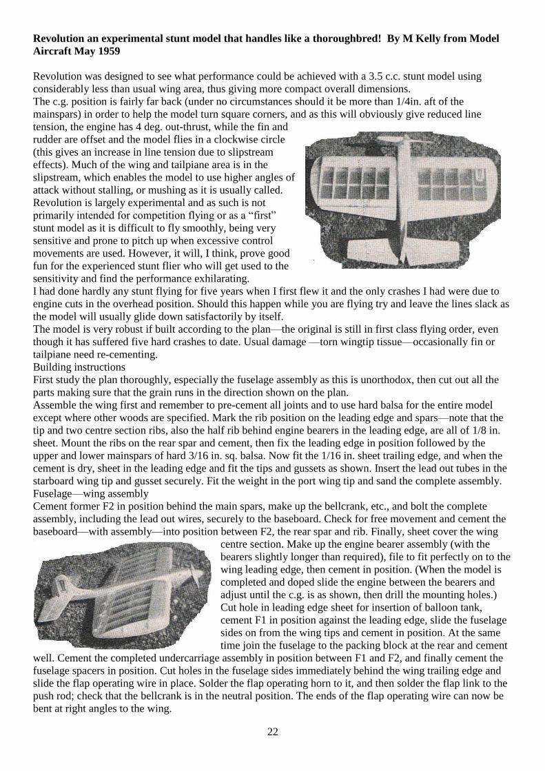
Revolution an experimental stunt model that handles like a thoroughbred! By M Kelly from Model
Aircraft May 1959
Revolution was designed to see what performance could be achieved with a 3.5 c.c. stunt model using
considerably less than usual wing area, thus giving more compact overall dimensions.
The c.g. position is fairly far back (under no circumstances should it be more than 1/4in. aft of the
mainspars) in order to help the model turn square corners, and as this will obviously give reduced line
tension, the engine has 4 deg. out-thrust, while the fin and
rudder are offset and the model flies in a clockwise circle
(this gives an increase in line tension due to slipstream
effects). Much of the wing and tailpiane area is in the
slipstream, which enables the model to use higher angles of
attack without stalling, or mushing as it is usually called.
Revolution is largely experimental and as such is not
primarily intended for competition flying or as a “first”
stunt model as it is difficult to fly smoothly, being very
sensitive and prone to pitch up when excessive control
movements are used. However, it will, I think, prove good
fun for the experienced stunt flier who will get used to the
sensitivity and find the performance exhilarating.
I had done hardly any stunt flying for five years when I first flew it and the only crashes I had were due to
engine cuts in the overhead position. Should this happen while you are flying try and leave the lines slack as
the model will usually glide down satisfactorily by itself.
The model is very robust if built according to the plan—the original is still in first class flying order, even
though it has suffered five hard crashes to date. Usual damage —torn wingtip tissue—occasionally fin or
tailpiane need re-cementing.
Building instructions
First study the plan thoroughly, especially the fuselage assembly as this is unorthodox, then cut out all the
parts making sure that the grain runs in the direction shown on the plan.
Assemble the wing first and remember to pre-cement all joints and to use hard balsa for the entire model
except where other woods are specified. Mark the rib position on the leading edge and spars—note that the
tip and two centre section ribs, also the half rib behind engine bearers in the leading edge, are all of 1/8 in.
sheet. Mount the ribs on the rear spar and cement, then fix the leading edge in position followed by the
upper and lower mainspars of hard 3/16 in. sq. balsa. Now fit the 1/16 in. sheet trailing edge, and when the
cement is dry, sheet in the leading edge and fit the tips and gussets as shown. Insert the lead out tubes in the
starboard wing tip and gusset securely. Fit the weight in the port wing tip and sand the complete assembly.
Fuselage—wing assembly
Cement former F2 in position behind the main spars, make up the bellcrank, etc., and bolt the complete
assembly, including the lead out wires, securely to the baseboard. Check for free movement and cement the
baseboard—with assembly—into position between F2, the rear spar and rib. Finally, sheet cover the wing
centre section. Make up the engine bearer assembly (with the
bearers slightly longer than required), file to fit perfectly on to the
wing leading edge, then cement in position. (When the model is
completed and doped slide the engine between the bearers and
adjust until the c.g. is as shown, then drill the mounting holes.)
Cut hole in leading edge sheet for insertion of balloon tank,
cement F1 in position against the leading edge, slide the fuselage
sides on from the wing tips and cement in position. At the same
time join the fuselage to the packing block at the rear and cement
well. Cement the completed undercarriage assembly in position between F1 and F2, and finally cement the
fuselage spacers in position. Cut holes in the fuselage sides immediately behind the wing trailing edge and
slide the flap operating wire in place. Solder the flap operating horn to it, and then solder the flap link to the
push rod; check that the bellcrank is in the neutral position. The ends of the flap operating wire can now be
bent at right angles to the wing.

23
Make up the tailplane and elevator and fit the horn in place. Connect the push rod to the horn and secure
with a dab of solder so that the push rod cannot fall out. Cement the tailplane in position checking for
neutral setting of the elevator—it is important at this stage to ensure that the flap and elevator are correctly
synchronised to give a 40 deg. each way movement of the flap to a 6o deg. each way movement of the
elevator. The tail skid can now be fitted and the upper and lower fuselage halves sheeted in. Round off the
edges with sandpaper and fit the stooge loop at the tail. Cement the fin and rudder in position, and cover the
wings, fuselage and tailplane with lightweight tissue. Dope the fuselage with a mixture of talcum powder
and dope to seal the paper and sand smooth with flour paper. Apply three coats of clear dope to complete the
model and finally a coat of colour trim to the fuselage only.
Fuelproof the balloon box by pouring clear dope through the hole in F1 and rotating the model several
times, pouring out the residue. Bend up the loops in the end of lead out wires. Fit the engine and make the
cowl—try beating it from aluminium over the end of a broom handle—it’s not very difficult.
A good balloon tank is simple to make, the only thing to remember is not to leave sharp edges on the
notched end of the tube, and not to bind the balloon too tightly in place or the fuel flow will be restricted.
The tank can be fitted into its box in the leading edge (between F2, the leading edge sheet and the half rib
and centre section rib) either by pushing it through the hole in F1 with a piece of well rounded off and
sanded dowel, or by cutting a hatch in the top of the fuselage between F1 and F2.
Balloon tanks operate very well once the art of filling them and removing any air bubbles has been
mastered, but a new balloon should be used for each day’s flying. Puncture of a tank can be diagnosed by
fuel pouring from the drain holes in the tank box.
Use full up elevator for your first take-off if you are flying over grass because of the small wheel size.
Immediately Revolution is airborne centralise the controls and let the model climb to a safe height before
levelling off. Note that the climb may well be vertical! but the model will, even so, hold tight on the lines.
From Jörgen Daun
Hi James like to show what I’ve done so far this winter. First the Ballerina from Old School one of very few
that I covered in Solite and the Chatterbox that is almost ready for covering just final sanding before
covering also from Old School and last is the Popsie from Belair also ready for covering. As you I am not a
good photographer.
Ballerina Chatterbox

24
Popsie
(See adverts page JP)
Bill Morley’s Thunderbird from Peter Tindal
Bill Morley is a good friend of mine and as you may remember I did a bit a while ago about his
Thunderbolt.....sadly no longer.as it only lasted 5 flights.........bit upsetting for me as I don't tend to break
stunt models very often.......however.......I would like to pass on a bit of advice, which I have run past Bill
(who is in agreement) regarding cg. The cg needs to be anywhere between the spar and the pivot point,
depending on your style of flying, however the front leadout will need to be moved to be about 1/4"behind
the cg .......this is to elevate the tendency for the model to go light on the lines (or in my case.....too light on
the lines!!) if the model is flying a bit on the slow side If you want to use original exit positions, I would
suggest balancing on the spar and fly fairly fast on 60ft lines..hope this helps and I can certainly recommend
Derek's kit...cheers Pete Tindal .......Photo attached. copy of a photo taken at Bills end of last year

25

26
(Fuller version than in issue 30)
Pipistrelle. unusual tailless rubber model for the sport flyer by G Wools Model Aircraft February
1953
Pipistrelle is the result of a desire for a model of unusual appearance which could be flown as a sport model
within a smallish flying ground. Experience gained with the biplane Dragonfly (M.A., March, 1951) which
had a sharply swept back upper wing, indicated that a tailless model would probably “fill the bill.”
While Pipistrelle is not claimed to be the ultimate
tailless design, it has been flown regularly for some
six months or more, and has shown a consistent
performance. Stability under power is of a very high
order, and its ability to fly well and quite steadily in
very gusty conditions is quite remarkable.
Fuselage
This is of the elementary box type with the two sides
built directly on the plan, one on top of the other.
Before separating, add the extra 1/16-in. sheet at the
rear rubber peg location, and drill a pilot hole, about
1/8 in. diameter through both sides, and the holes for
wing hold-down dowels. Assemble the two sides and
fit the central stringer along the bottom of the wing
groove last.
Mainplanes
A little more detail may be of help here, for the 10 deg. wash-out is built in—this is preferable to building
flat and warping afterwards. Make template of root and tip ribs from ply, or preferably tin-plate. Sandwich
nine pieces of 1/16-in. sheet between them, hold in place by long pins through the lot and shape down the
balsa, cut the slots for the spars. Make two sets of ribs, right and left hand. The 3/8 in. x 1/8 in. trailing edge
should be cut to length and notched to suit the ribs. Wing tips and root ribs are cut from 1/8-in, sheet, the
latter using the root template but with the bottom left flat. The slot for the lower spar must therefore be
deeper. Assemble by laying down the L.E. and the root rib flat on the plan, the rib should lean inward
slightly against the dihedral template. The wash out template is laid on the plan under the wing tip, and the
tip and T.E. assembled. Now the ribs are fitted taking care that the T.E. which does not touch the plan except
at the root end, remains straight. Fit 1/8 in. x 1/16in. top spar and when all is dry, remove wing from board
and fit lower spar. The fitting of wing-joining dowel tubes, etc. should be straightforward. The front of the
wing tip should be 3 in. above the bottom of the root ribs, i.e. 3 in. dihedral under each tip.
Elevons
These are fitted to the wings by means of C/L elevator type hinges. After covering, a balsa “horn” is
cemented to the devon. A rubber band retains the elevon at its correct angle and adjustment may be made by
thin card packing cemented under the front of the “horn.”
N.B.—The use of the usual aluminium hinges was discontinued due to the difficulty of adjusting accurately,
and their liability to be knocked from their setting if the model overturned on landing.
Cover the entire model with ‘tissue and dope. Use a few drops of castor oil in the dope, especially when
treating wings and fin, in order to prevent warping.
Flying
Eight strands of 1/4 x 1/24 Dunlop rubber from 36 in. to 42 in. long is recommended. This should be pre-
tensioned. First check for warps, i.e. see that the wing, L.E. and T.E. are straight, and that the wings have
similar “ washout.” As a start, adjust the devons to an angle of about 30 deg. to the wing tip, and assemble
wing on fuselage so that the model balances at 3/4in. from the T.E. at the centre section.
Given a calm day, hand glides may be indulged in, slightly less negative elevon angle may be used if stalling
results, but if a considerable change of angle from that given is required, move the wing back a little. In the
case of” dives,” reverse above procedure.
The prototype is very safe under power, even on full turns, so powered flights may be started quite soon. A
L.H. turn—with torque—is recommended and this may be accomplished with a combination of thrust off-set
27
and rudder. Elevons can be used for turn, but make adjustments very carefully as they are extremely
sensitive.
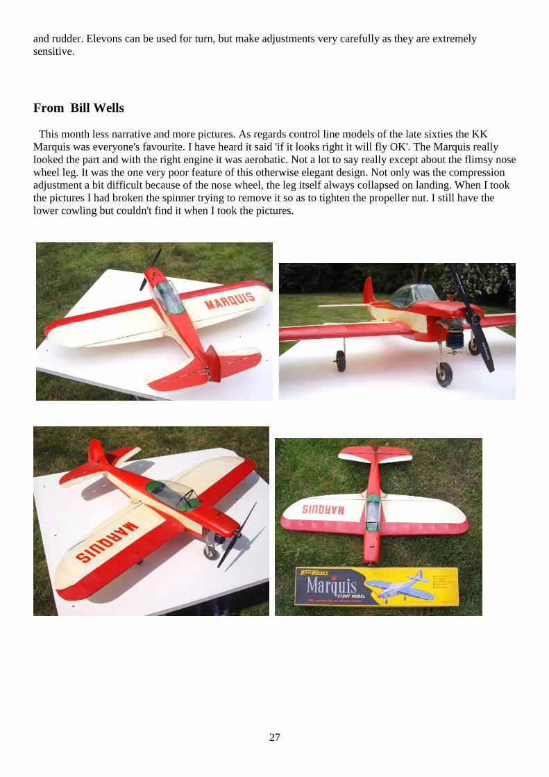
From Bill Wells
This month less narrative and more pictures. As regards control line models of the late sixties the KK
Marquis was everyone's favourite. I have heard it said 'if it looks right it will fly OK'. The Marquis really
looked the part and with the right engine it was aerobatic. Not a lot to say really except about the flimsy nose
wheel leg. It was the one very poor feature of this otherwise elegant design. Not only was the compression
adjustment a bit difficult because of the nose wheel, the leg itself always collapsed on landing. When I took
the pictures I had broken the spinner trying to remove it so as to tighten the propeller nut. I still have the
lower cowling but couldn't find it when I took the pictures.

28
From Peter Scott
I have been teaching myself how to upload videos onto YouTube, have a look at the first flight in 1995 of
my 8ft span Bowden Low Wing Monoplane
http://www.youtube.com/watch?v=DTUn0pX0i-8
Plus photo attached, taken in 1995, I still have the model but haven't flown it for at least a decade, I should
drag it down from the loft.
I just wanted to signpost readers of S&T to a source of SAE70 oil (if it was good enough for Colonel
Bowden, it's good enough for me !). It really does make a difference to the smooth running of Sparkies,
see
http://www.ebay.co.uk/itm/320780256961?ssPageName=STRK:MEWNX:IT&_trksid=p3984.m1497.l2649
David Kinsella’s Column
Good Reading
Prepared with enthusiasm by Messrs Lever and Waterland, the SAM 35 Yearbook is ready! A Vintage
essential for the shelf, packed with all the good stuff we like to read
and read again, following the tradition and principles laid down by
Peter Michel, the ‘yearbooks return is most welcome and deserves
strong support. Lifting the lid a little, VTR expert David Finch
delivers a detailed account of Team Racer construction step by step.
A dozen years ago now, VTR 2000 celebrated the first fifty years of
the sport in Great Britain. Via the Yearbook we return to Old
Warden and that memorable weekend in July, to the models, the
stars, the racing and the prizes — and the enjoyment of being part of
something that was really worthwhile. And the winner — flying a
classic Phil Smith design — was David Finch Good stuff not to be missed. Here’s a few of the pilots.
That Healey
Run over closed public roads, the still Bentley—era Le Mans of
the 1950s was hosting the first of the supercars nudging 200mph.
So narrow through the pit area that folk on one side could chat to
those on the other, a disaster really was only a matter of time……
Well into the 24 Hours in 1955, a D-Type swung right for the
pits. Stepping left to avoid the slowing Jaguar, the modest Healey
100 was now in the path of a charging Mercedes 300SLR — in
top good for 180 plus. Fully restored, the Healey that was the
launch ramp for the 300SLR was sold recently for £843,000.

29
Capital’s Wood
In London and short of balsa? Modelzone in Hölborn and Ian Allan by the side of Waterloo station hold
ample stocks and, of course, much else in the way of cast models, plastic kits, books and magazines.
Naturally enough Ian Allan is strong on railways, being close to where Ian Allan himself launched his
series of train spotting booklets long ago. He was a Southern Railway man.
Like Reg
VTR buffs finding themselves in Webster Road, Walsall, may not know that another racer — Sidney
Webster (later Air Vice Marshal Webster) — was born in nearby Borneo Street. A railway clerk, he joined
the RFC, then the High Speed Flight, winning the Schneider Trophy in Venice in 1927. National hero
As a result, parades and parties celebrated the dashing pilot of the S5 designed by R J Mitchell, another
Staffordshire hero.
Down Below
Tube stations come and go. Some 26 stations are closed up but still exist (such as Trafalgar square) while
others are re-named (Embankment for example) and carry on. Closed Brompton Road served as the AA’s
gun control centre where a large map still shows the areas to the south and east under threat.
Furnished and with small arms racks in place, one room witnessed the long interrogation of Rudolph Hess
who parachuted into the Duke of Hamilton’s Scottish estate. Even parts of his aeroplane were brought to
London where they may be seen at the Imperial War Museum.
The Unexpected
Rejected to begin with, Forsyth’s Jackall (11 million), Harry Potter (vast) and Treasure Island (running since
1883) were all out of the rut. Performing strongly since 2006, The Dangerous Book for Boys has been
reprinted twenty times. Crammed with much traditional, even old fashioned, info — heroes, tree house
design, soap box carts, camping and hobbies numerous — the big red book with its gold trim ignites happy
memories or desires to grasp what was missed first time round. Our tree house (in a wood long gone)
required a huge ladder for us to reach the first branches, then up we’d go to the roofed platform where even
a coal fire was lit! These days HSE would have a fìt!
In The Pink
Invented by Frank Hornby but long gone from Liverpool’s Binns Road, Meccano
marches on in France. Launched in 1901, mighty structures like the Block Setting
Crane got many a lad on his way to an engineering degree and then a spot of serious
construction somewhere in the Empire the Meccano Magazine
at least in his ant-proof trunk. We can imagine him now, addressing a rather ticklish nut
with his spanner while termites munch at his BSc on the wall.
In Hot Water
People who should know better bend history or apologise for events of long ago. What’s the point?
Constantine may have been Great but he still boiled his wife. Even the goodies were baddies back then. Get
real, gentlemen.
Eaton Bray
The ambitious modellers village intended north of London in the early 1950s featured a large circle for
model cars. 1066 and others were building cars, kits and bits for this
interest here we have a 10cc racer of the times ready to go. All of 16 in
long, a centrifugal clutch delivers power from the 1066 motor to the bevel
gear front wheel drive and fine adjustment re line tension is achieved by a
tweek on the rear axle. The big wheels feature finned brake drums and a
matchbox indicates general dimensions.

30
Boats Surviving
With 2000ft of Gauge O track at their disposal , Hermann Goering and his
nephew tend a goods train going through. By the hunting lodge near Berlin
there’s galleons and other models on the lake. For distance work on canal and
sea motor yacht Carin II is crewed and ready to sail. Hitler’s much larger yacht
Grille (meaning whim or cricket) - elegant with clipper bow, masts funnel and
decorated stern - was often pictured with the Kriegsmarime’s capital ships and
served as a U-Boat Control vessel. One of Grille’s motor launches still sails in
the Med and Graf Spee is visible in the River Plate
Shadow World
Its products and influence spread around the world, the vast arms industry operates just below the radar and
its exhibitions and sales drives go for the most part unreported. Seven figure tips and the occasional jet liner
help things along, countries ending up with hardware beyond their budgets and abilities to operate! What did
hit the headlines a while, back was the giant gun built in big sections for rocket-like application. Some said
it was part of an oil rig, but a length on display at Woolwich contradicts this view. A big calibre job
appeared with Sinatra and Loren in the screen version of C S Forrestor’s The Gun (I957 But for adventurous
stuff these days and solid fact too read The Shadow World and meet Zaharoff and other high rollers of the
second oldest profession, their deals and moves making bankers mere match sellers
by comparison.
Dates
Time sprints on and that kit you bought at the last Watford is still on the shelf! Never
mind, all too soon the huge Guild of Aviation Artists Exhibition will be here again
and the dates are 16 to 22 July It’s just five minutes from Trafalgar Square. Also not
to be missed this year is the big Epsom Show at the NESCOT campus on 28 & 29
April which marks sixty years of Epsom & Ewell Model Railway Club (see S&T No
58). Planes or trains, both events are well worth a visit and attract the best in the
business.
Your View
Messrs Ferguson, Kynastan. and Roberts write the history I like to read. With much in print, David
Kynaston’s recent lecture on the City reminded us of its great age and lively history. Dick Whittington is a
favourite panto subject but how many recall that wealthy Whittington funded Agincourt in 1415. Henry
did the business but Dick delivered the sinews. What the cat did is not known.
Earlier Island
Watkin’s words and reels on seals gave Disney an Academy Award for
Seal Island. Soon Treasure Island was rolling at Denham thanks to a
treatment by Professor Watkin, Byron Haskin directing for a modest
25,000 dollars although it was 1949. Bobby.Driscoll (as Jim) was ordered
back to the US because he didn’t have a work permit, but toiled flat out to
cover his scenes in the appeal period (which he lost). Air Marshal Tedder
and other swells taking an interest, Haskin left aboard Queen Mary while
others trimmed Freddie Young’s work. Seen in the US in final cut, Haskin
sent for everything and with Watkin chopped and then built the movie we
know today. A younger lad is, Jim in long shot, but Newton is Long John
Silver from start to finish with rolling eye and mannerisms the stock in
trade of any pirate worth his salt. Classical
too (with Olivier in Henry V) a fishing trip in Ireland and asked to find a suitable Ben Gunn Inspired
Newton to hit his marks and make the movie.

31
Back To Black
Good to read Bill Wells on his days with the ED Racer, soon a high profile motor when it appeared in the
early 1950s Scan our mags of ages and we will see the beautiful device doing well in all applications, even a
couple in a Mosquito for Scale fellows. Basil was proud of it and what it achieved — Speed record with Pete
Wright’s Gook for a start — but was horrified when I showed him a later marque with a plastic backplate!
Basil and Flo Miles always sent Christmas cards and for many years received them from the Bird’s
Custard family because of shared interests in modelling. Collar a good Racer with a black crankcase and
Mike Crisp will work his magic to good effect.
Super Mac
Racer rested for a while way back then, we’d turn to the Eagle for lots of good reading, fact and fiction
deployed like no other. Star turn when it came to jaunts in the
Kalahari, charming snakes in India or punching cattle in Alberta,
Mac Hastings was our man — our hero on a camel, in a biplane or
starving on a desert island. It was ages though, before I realised that
Max Hastings was Mac’s distinguished son, editor, author,
historian, enthusiast of England’s countryside, world traveller and
adventurer himself. Eagle
Special Investigator Mac Hastings, recruited at the Savoy by
founder Marcus Morris, made the blaze of colour that was Eagle the
UK’s best comic, Frank Hampson’s Dan Dare leading the way. At
Hatchards I was able to tell Sir Max of Eagle’s amazing arrival. Nothing like it before — or since!
Winning Cards
A postie-bustng crop of Christmas cards confirmed that we modellers are men
of tradition, one posting from Christmas Island! Raynes Park MAC
remembered Vic Smeed with his Mam’selle (as here) while another celebrated
exemplar of true grit Sir Douglas Bader OBE DSO DFC, pictured returning
home in Wing Commander days aboard Spitfire D-B puffing his pipe
(Galland preferred cigars in the cockpit). Sveral cards gave S&T thumbs up for content.
Pricing
One or two swap meets didn’t happen last year. Lower turn outs were reported elsewhere. Wisely tickets for
the big Gauge O show at Reading were trimmed back, numbers holding up well. But times are tight and it
beboves all with a hand in these things oa remember that a high percentage of modellers are shufflers and
not high rollers trading stocks. £9 at the gate and £1.75 for a can proved too much for some last summer.
And once lost, will the retired gent get used to the idea and not return? Thinking caps on, lads. The fate of
future shows is in your hands. High volumes are what’s needed.
Yearbook Ahoy!
Again, thanks to Brian and contributing chums the SAM 35 Yearbook is fact. An item in demand to stand
alongside the many produced by Peter Michel, he who hestitates.... So rush your order to Ron. Knight (0208
878 7041). The rare and distilled juices of our great hobby await between the covers of this delightful gem.
It’s reading you can trust in conditions you can’t.
Barryr’s Best
These days Barry Freeman’s work graces great boxes from Hornby and
hangs in homes around the world. His Christmas card featured Gresley
A4 Kingfisher in blue, reminding me of the start of the A4 project
sparked by high speed happenings in Germany in the 1930s. But Gresley
stuck with steam, his stunning streamliner marking the Silver Jubilee of
King Emperor George. V. And here’s the engine and train, storming
north through Hertfordshire, Silver Link with her scoop down hoisting
hundreds of gallons in seoonds.

32
Ace Remembered
Plans to remember 56 Squadron ace McCudden VC are moving ahead, the aim being a centre at Halton, so
rich in RFC and RAP history. What a grand idea.
Muscle Machine
Avast, the beastie comes! A nautical warning fits because the boiler for this
sensation of the LNER came from Yarrow, purveyors of pressure vessels to
ships and battleships worldwide. Powering Hush-Hush, the Alien-like high
pressure bailer (S&T No 53) fed a 4-cylinder compound system. The new
Gauge O model from Laurie Loveless (01423 712 446) is big, impressive and
detailed to museum standards. Rightly in my view, Laurie concentrates on the
big blasters of the main line, the heroic hairies that stormed north the golden
age of steam traction. Remembering a Scottish Duke, Cock O’The North soon
followed, Laurie making an excellent model to match.
Bits
Numbers given several times, Messrs Crisp, Goodall, McDonald, Robinson and Winter will assist with VTR
creation worthy of the chequered flag. Top hole!
A Reader’s News
And here’s a fine brace of models from reader Eddy Boddington, dedicated to real
aeromodelllng as campaigned by SAM 35 and Sticks & Tissue. Tiger and Comper
Swift pictured here — delightful too — a Morane Saulnier is under construction for
electric power. Some of Vic’s great designs, certainly a
- Tomboy or two, are scheduled and ready for use is an ED 246 Racer brought from
Christchurch, New Zealand. I met Eddy at the MEE last year, he on a long haul from
Cumbria, and he took some pictures of me manning the super Raynes Park MAC stand
set out with models from Mike Cummings, Malcolm Jagger,
Alan Walker and Ted Horne. ARTF at lea.t gets feet to the flying field but, Eddy feels,
the essential element is absent. Who would disagree? ..
Simple is best
When at Cashmoor the other week Chris Hague produced his lines for a spot of control line flying and this is
the idea he’d come up with. Bloomin’ marvellous.
An old DVD / CD stack and your lines are safe, dry, won’t spring out all over the place when you drop them
or unravel in the model box.

33
From Roger Cooper
Here is the article I mentioned yesterday. The Vintage Motorcycle Club are happy for it to be reproduced in
S&T and I will forward separately in a moment the relevant e-mail correspondence.
This article may fit in with your "alternative S&T".
I must confess I never realised Col Bowden was also interested in motorcycles and cars, but I have always
admired his classic model aircraft designs.

34

35
Imp a 48” slope soarer for radio control from Aero Modeller October 1970
T. KING provides a simple boxcar for club field sport flying that will appeal to all modellers
THE IMP was created with small field flying in mind, as the designers club (The Impington Village College
M.A.C.) has only a small playing-field surrounded by large trees — typical of many clubs throughout the
country. Most evening’s flying end up with a tree climbing adventure —alright for the youngsters, but it gets
harder as you get older! With the arrival of cheaper single channel radio it meant the average club member
could afford to control his model to some extent, and a glider offers the perfect entry into R/C flying.
‘IMP’ No. 1 was built in the summer of 1967. What a delight it was to be able to turn away from trees,
which before had greedily swallowed up one’s model! Using a Hi-Start
launch to take the model up to about 250 ft., a flight of one to two
minutes seems quite a long time in a small field. Being enthused with the
performance, ‘IMP’ No. 2 was built for Ray Malmstrom (founder
member of the club) as an introduction to R/C. The first flight was made
one evening in the summer of 1968 with Ray at the control. The model
was stretched back on the Hi-Start. At a signal from Ray the model was
released. It rapidly gained height, with a few minor rudder corrections.
After a clean release at the top, Ray proceeded to do a few circuits of the
field. Apart from over-correcting once or twice, he had made his first
R/C flight without mishap. Had it been a powered aircraft, those one or
two over-corrections might have spelt disaster.
Although flights of only one or two minutes in a small field have been mentioned, in more open space with a
higher launch flights of five minutes and over have been enjoyed.
Start by building the fuselage sides. These consist of 3/16 in. sheet combined with built-up 3/16 in. x 3/16
in. balsa. When dry, join at rear. Now add ply formers F2 and F3, also 1/2 in. x 3/16 in. balsa spacers top
and bottom. Next fit nose-block and former F1. Now add ply former F4 complete with 3/16 in. x 3/16 in
spacers top and bottom. At this stage place ¼ in. x ¼ in. balsa torque rod in position. Bend 18 s.w.g. wire at
rear end, push through hole in F4 and bind and glue into rear of torque rod. Now add the rest of 3/16 in. x
3/16 in. spacers, and other balsa and ply pieces shown on plan at rear of fuselage.
Next add 1/8 in. ply skid complete with 16 s.w.g. wire tow-hook. 1mm. ply must now be glued to top and
bottom of fuselage, at the same time forming hatch for the battery
compartment.
Pin the 1/8 in. sheet wing main spar down with 1/32 in. sheet
packing underneath. Next, pin down 1/16 in. sheet trailing edge
lower section. Now add 1/16 in. sheet ribs, and 3/16 in. x 3/16 in.
leading edge. Next add 1/16 in. top sheeting and 1/32 in. capping
strips. When dry remove from board, prop up centre section and
complete outer panels in the same way. When dry turn over and
complete 1/32 in. sheet and capping strips. Lastly, add 1/8 in. sheet
gussets and 1/4in, sheet tips.
Ray Malmstrom holds on to the Imp prototype ready for launch
Pin down the tailpiane trailing edge, leading edge and 3/16 in. x 1/8 in. centre spar. Glue 1/16 in. ribs in
position, add top 1/8in.x 1/8 in. spars. Lastly, add 3/16 in. sheet tips, 1/8 in. sheet gussets and 1/32 in. top
sheet.
The fin is quite straightforward and is glued to the fuselage entering 1 / 16 in. sheet fuselage top where
shown on plan.
A Cotswold Rx and Elmic Conquest actuator, with a 225 3.6v. Deac is used in the original.
After sanding the airframe, give one coat of sanding sealer. Sand lightly once more. Cover fuselage,
wing and fin with heavyweight tissue. Use lightweight tissue on the tailplane. Give the whole aircraft three
coats of 50/50 clear dope. On the original the fuselage forward of the tow-hook position is painted with
Polyurethane, giving a durable finish to parts most prone to damage.

36
Check there are no warps. If any, take out with steam. Balance to model where shown on plan. A flat glide
should be aimed for. If the model stalls add packing under leading edge of tailplane, if a dive occurs add
packing under trailing edge of tailplane.
Launching
For a Hi-Start launch, you need about 30 yards of 1/4in, flat elastic attached to a stake firmly driven into
the ground. Add to this about 100 yards of 13 lb. B.S. Monofilament fishing line, to which is tied a cloth
pennant and tow-hook ring. Hook on to the model and walk back 30 yards or so until a good pull is felt.
When the model is released, it will rise rapidly at first, but on reaching the top of the tow it will flatten out
and fly off the line at the correct speed. On a breezy day it may kite for a while before flying off the line, in
which case keep model into wind until it is released. If you try to turn the model while on the line in an
effort to release it, you could end up with a broken wing, especially in windy conditions. One note of
warning when using the Hi-Start—-make sure the radio is working 100 per cent, as you are committed once
you have released model, and an uncorrected veer to left or right will spell disaster!
The Hi-Start described is for small field flying, a doubled power (two strands of elastic) version will give a
good high release when flying on an aerodrome or similar open space.
Now get to the board and make a start!
Simple lines, straight structure (although total weight is
only 12 ozs.) makes Imp a perfect project which could be
bult in a week of evenings quite inexpensively and capable
of taking a wide range of single channel equipment.
HI-STARTS FOR FF GLIDERS from Dave Platt
About 20 years ago I was heavily involved in all classes of FF. This lasted some 10 years but then I kinda
overdosed on it, as you do, and went back to RC Scale for awhile.
This phase lasted similarly for about 10 years until the urge for FF bit again. But now I found that, at the
age of 77, things had changed. I designed and built a nice 8'-span towline glider but found to my horror I
couldn't tow it up as I can no longer run. Not even those first few steps to get things started.
What to do?
A dim memory came to me of a day in about 1945 in Clayhall Park in Ilford when I watched a pair of older
boys flying an all-balsa glider (perhaps a Skyleada Three-Footer) on a small hi-start. The glider would kite
up, release, and sail around nice as you please. This might be the answer!
A search in the modelling literature and on the Internet produced no useable information; all of the data on
hi-starts concerned RC, not much help to me. Apparently, I was going to have to wing it alone.
For my "String of Pearls", at 8' span, 750 sq. ins. and 34-oz. weight I figured 3 or 4 strands of 1/4-flat should
do the trick. I laid out my hi-start as recommended by L G Temple in his book "Model Sailplanes" at 50' of
rubber and 150' of line.
First attempts proved disappointing to say the least. Upon release the model would shoot up, stall wickedly,
stay hooked and stall again, then a third time until casting off at about 30' of altitude. Fortunately, no
damage.
Must be hook placement! I had the hook in the usual place for a hand-towed glider -- right about 50%
chord, where the CG is. Back in the workshop I moved the hook forward an inch or so. Next trip showed
no improvement whatsoever. Let's move it another inch. Same result.
Hmmm.
Too much power? I backed off to 2 strands of 1/4 rubber. Sure didn't look like much rubber to pull up such
a big glider. But, there was a slight improvement, the model getting a little higher but still stalling like mad
on the climbout.

37
Maybe the hook was still wrong? At this point I made a strip of plywood comprising several hooks and
buried it in the bottom of the fuselage. These hook positions went all the way to the LE of the wing.
If you've stayed with me this long you must be getting bored by now so I'll cut to the chase. After a
considerable number of trips to the field and countless attempts, I finally found the answer. The best
position for the hook turned out to be the one at about 20% of the chord, a full 4" ahead of the original
location. Also, by noticing that the climbout was much smoother when I didn't walk back very far, I
realized that the rubber was still too strong. By using only one strand of 1/4 flat, the end result was a perfect
graceful climb, the model kiting up to the full length of the line, releasing at some 150' or more. Enough for
a 2 to 3-minute flight in calm air, more with any lift around.
It is important that the hi-start be laid out very close to dead into wind. If not, the glider will weave left and
right as if seeking to weathercock. The best height is achieved when the launch direction is just right.
With excellent results now commonplace, I built two more gliders, a 72" span, 480 sq. in. 16-oz. job (one
strand of 1/8" rubber) and a little Mercury Swan that weighs a mere 4-1/2 ozs. This one uses a single strand
of 1/16" sq. rubber. All of the hi-starts have 50' of rubber and 150' of very light braided fishing line, 50-lb.
test.
A swinging-arm mechanism works well for the auto-rudder (see photos).
If like me, for whatever reason you cannot tow up a FF glider any more, here's a way you can still enjoy
them. Don't forget the DT!
Under construction is a twice-size "Tiara" -- 12' span.
These small insets show the
interior swinging-arm auto rudder
trigger, the other one the DT
arrangement.

38
The big glider is the
O/D "String of Pearls",
the medium-sized one is
my O/D "Tiara" and the
little one is a Mercury
"Swan". The Swan is
slightly modified to
have a sub fin to
facilitate auto rudder
hookup.

39
James, Hope this may be of interest to the readership. Regards Bob Pickernell
I was fascinated by Stephen Winkworth's piece on his slatted wing model which I presume is a variation on
the Flying Washboard design. I loved the puns and wordplay, Stephen. What is interesting is this is a great
example of people in different places coming up with the same idea. Dr Hermann Kayser is credited with
this idea from 1965 but Barnes Wallis came
up with the same idea in the late 1950s and
proposed a bomber to the MOD 28/01/60.
Using multiple slats hinged inside a delta
wing a V bomber replacement was offered
that would take off in a 500(5 hundred!) foot
run and cruise at Mach 4.5. Given the level of
secrecy that was prevalent at the time I very
much doubt if there was any crossover
between the 2 good doctors. The multiple
wings would fold flat with the wing surface
after take off and be redeployed for landing.
The project was given the code name
Cascade. Attached a sketch of the cascade
concept.

40
Adverts
From Jon Fletcher in Oz
Received the latest S & T, many thanks! Picked up on the pic. Of the ETA 15 Mk I with "wrong assy.
screws" I make replica Philips head screws for the ETA 15's MkI through to III. Machined out of stainless
steel and forged Philips head recess then the head turned with formed tools to match the original head radii.
Lastly the heads are finely glass bead blasted to replicate the original satin nickel plate finish. Looks like
those I made fitted to a Mk III I rebuilt a while back. I make any special screw for $3.50 AUD ea. but if the
Owner of the ETA 15 Mk I was interested in a set I could work out a lower price. The rebuilt MkIII also has
exact replica spinner nut, prop. washer, prop. driver and NVA made by me.
I make any part for any model aero engine. Also do rebores and repair and upgrade Seelig Free Flight
timers and repair Tatone and KSB timers.
I have mainly specialised in English diesels of the 1950's and currently have small qtys. of parts for AM's,
Allbon, ED, Elfins, ETA, Frog, Mills, Rivers and Oliver and many other engines. I have specialised in
making exact replicas of the manufacturer's original parts.
By way of example attached is a pic. Of my Elfin 2.49 beam mount which has the prop. washer, prop.
driver, NVA, cylinder head, comp. screw assy. And back plate all made by me.

41
Updates: Single Channel fly-in - Sunday July 1st, 2012 PANDAS
Its just a reminder to keep checking the S/C event page on www.singlechannel.co.uk please as it's frequently
updated as things develop, thanks.
Also we've a couple of threads started on the RCMF Forum, whether you are coming to the Single-Channel
Fly In or not we'd really appreciate contributions to the thread, to keep it bubbling - we dont want any
rudder-waggers to miss out!
So what are you building, what are you flying, how is the thumb holding up?
If you're coming to the Fly-In, whats your plan, are you counting the days, like us? ;) winking
Here are the threads:
"Back to the Future" http://www.rcmf.co.uk/4um/index.php/topic,89857.0.html
"Single Channel Retro Fly-In"
http://www.rcmf.co.uk/4um/index.php/topic,89837.msg1041850.html#msg1041850
As ever, many thanks for your support, spread the word...
Phil & Shaun, pp PANDAS committee
Old School Model Aeroplane factory
Derek Foxwell now has a supply of Ballerina’s and Chatterboxes. 02086471033
From Belair
Popsie FF by Vic Smeed £32.00
No building the beautiful Popsie is easier than ever with a Parts set containing all the shaped wood parts,
such as bulkhead, formers, wing ribs, tip shapes for wing, fin and tail, plus dihedral braces and smaller parts.
Parts only suit the original Aeromodeller X-list plan.
http://www.belairkits.com/Productdetail.asp?Id=818
Post S&T
As I get older I tend to view things from the past in a different light, I suppose it’s the rose tinted effect and
good Old Days when the sun always shone and all events were flown to perfect weather syndrome.
It seems that models from the Classic period have never been in the forefront of modern aeromodelling not
like say vintage but now I really enjoy seeing some of the models from that era and looking at the plans.
Here are a couple of the RC plans I thought I’d include, models I’ve heard of and were I guess big in their
time but I knew nothing about.

42

43

44

45
NOT S&T
Following on from the photos of the model shop at The Southampton Hall of Aviation – Solent Sky
Museum I took a few full size snaps as follow, not all the aeroplanes at the museum are included :-
http://www.airmuseumsuk.org/museum/Southampton1/800/index.htm
The ex 1943 built Sunderland (JM715) converted to a Sandringham 4 and served in Australia (VH-BRC)
and Bahamas before becoming an exhibit in the early 80’s.

46

47
The following photos are of the Jet fighter seaplane Saro SR/A1 G-12-1
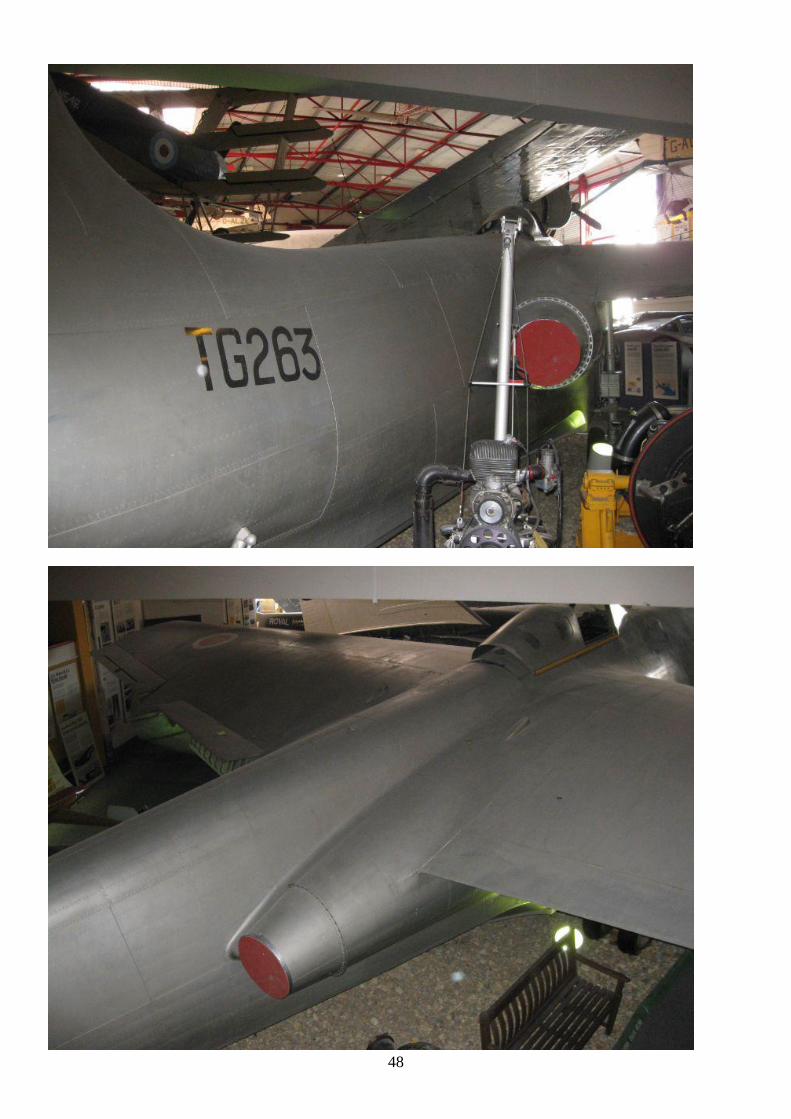
48
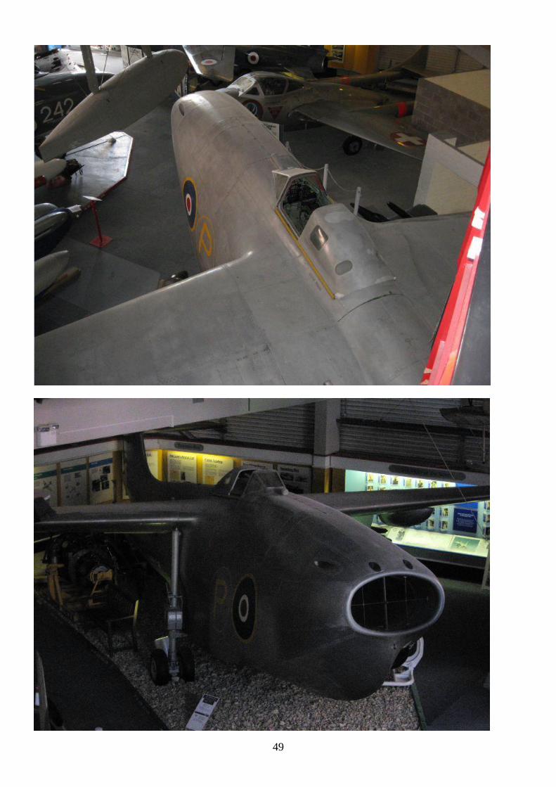
49

50
Following two are of the Sea Vixen

51
Spitfire F24 PK683
Next two are of Schneider trophy winner under reconstruction for new exhibition Supermarine S.6A - N248

52
Above is Slingsby T31B and in background Slingsby T38 Grasshopper TX1

53
Following two are Avro 504J C4451 (Replica)

54
Tiger Moth
Britten Norman BN-1F below
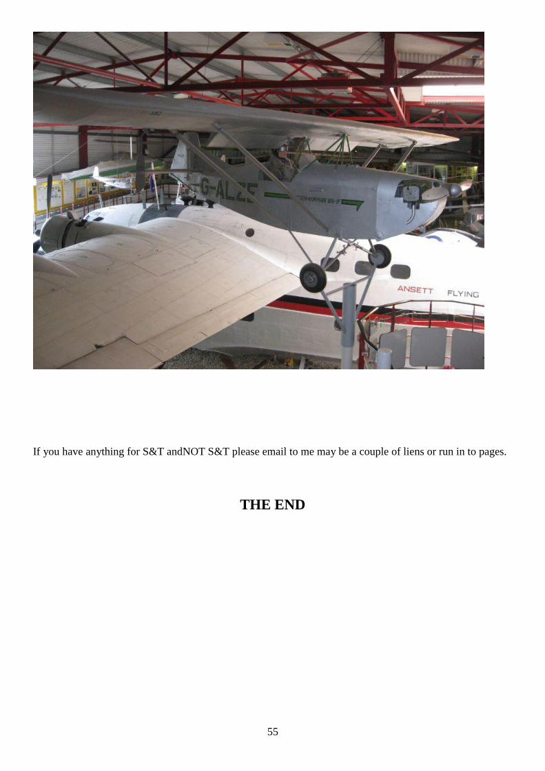
55
If you have anything for S&T andNOT S&T please email to me may be a couple of liens or run in to pages.
THE END