Embed Size (px)
Citation preview

Roboticahttp://journals.cambridge.org/ROB
Additional services for Robotica:
Email alerts: Click hereSubscriptions: Click hereCommercial reprints: Click hereTerms of use : Click here
Stiffness and singularity analysis of foldable parallel mechanism for ship-based stabilized platform
Tie-shi Zhao, Chang Wang, Xiao Liu, Hui Bian and Yan-zhi Zhao
Robotica / FirstView Article / July 2014, pp 1 - 12DOI: 10.1017/S0263574714001969, Published online: 17 July 2014
Link to this article: http://journals.cambridge.org/abstract_S0263574714001969
How to cite this article:Tie-shi Zhao, Chang Wang, Xiao Liu, Hui Bian and Yan-zhi Zhao Stiffness and singularity analysis of foldable parallelmechanism for ship-based stabilized platform. Robotica, Available on CJO 2014 doi:10.1017/S0263574714001969
Request Permissions : Click here
Downloaded from http://journals.cambridge.org/ROB, IP address: 138.37.211.113 on 18 Jul 2014

http://journals.cambridge.org Downloaded: 18 Jul 2014 IP address: 138.37.211.113
Robotica: page 1 of 12. © Cambridge University Press 2014doi:10.1017/S0263574714001969
Stiffness and singularity analysis of foldable parallelmechanism for ship-based stabilized platformTie-shi Zhao†,‡,∗, Chang Wang†,‡, Xiao Liu†,‡,Hui Bian†,‡ and Yan-zhi Zhao†,‡†Hebei Provincial Key Laboratory of Parallel Robot and Mechatronic System, Yanshan University,Qinhuangdao 066004, China‡Key Laboratory of Advanced Forging & Stamping Technology and Science (Yanshan University),Ministry of Education of China, Qinhuangdao 066004, China
(Accepted June 20, 2014)
SUMMARYThis paper investigates a 6-degree-of-freedom foldable parallel mechanism for the ship-basedstabilized platform, which is driven by closed chain linkages. The velocity and acceleration mappingsbetween the moving platform and inputs of the closed chain linkages are deduced in the formof the first- and second-order influence coefficient matrices. The continuous stiffness matrix isdeduced; furthermore, the translation and rotational stiffness along any direction are also deduced.With directional stiffness, the singularity of the mechanism is analyzed, and the explanation of thesingularity is given from the viewpoint of stiffness. The directions the platform cannot move or loseits constraints are got from directional stiffness.
KEYWORDS: Foldable parallel mechanism; Closed chain linkages; Stiffness; Singularity; Influencematrix.
1. IntroductionThe role of a stabilized platform is to provide a relatively stable working environment for a bumpycarrier (like a ship, vehicle, et al.) to improve the operational accuracy and safety.1–3 In recent years,much interest has been shown in stabilized platforms. However, most of these are 2-axis or 3-axisserial stabilized platforms whose bearing capacities are low, and they cannot counteract the motionsof heave and sway. It has been noted that parallel mechanisms can realize multi-axis coupling motionsand have the characteristics such as large bearing capacity and fast response,4–6 so they are the idealmodel for large-scale and multi-axis compensation stabilized platform. However, the application ofthe traditional Gough–Stewart platform is limited to structural height, so foldable parallel mechanismis considered. Most of the foldable mechanisms are better used in the situations that need to changethe form7,8 than those that need to output power. It is because foldable mechanism consists of lotof bars realizing foldable ability, which makes it easy to get into a singularity. The stoke outputof foldable mechanism is generally larger than the input of drive, hence the stiffness of a foldableparallel is terrible without some reasonable processing.
The singularity is a very important parameter of mechanism. When a mechanism is in singularity,the degree-of-freedom (DOF) of mechanism changes instantaneously. Gosselin and Angeles9 dividedthe singularity of closed-loop chains into three main groups. Zlatanov et al.10,11 introduced a newclassification and identification method for singular configurations of mechanisms. The classificationof singularities is based on the physical phenomena that occur in singular configurations rather thanthat on the mathematical concept of degenerating Jacobians. Chung et al12,13 proposed a new type of3-DOF foldable parallel mechanism having three foldable sub-chains, and analyzed the singularityand drew singularity loci.
* Corresponding author. E-mail: [email protected]

http://journals.cambridge.org Downloaded: 18 Jul 2014 IP address: 138.37.211.113
2 Stiffness & singularity analysis of foldable parallel mechanism for stabilized platform
pitching
rolling
heaving
s
sz
sx
sy
'o'z
'x
'y
o
z
x
y
yawing
surging
swaying
Fig. 1. Motions of a ship in the sea.
The stiffness expresses the bearing capacity. Joshi and Tsai14 chose maximum and minimumstiffness as performance indexes, and concluded that tricept manipulator is better conditioned than3-UPU manipulator. Shin et al.15 introduced the stiffness analysis of the Eclipse-IA structure toexamine the isotropy of stiffness matrix. Dai and Zhao16 analyzed the stiffness characteristics of two-link under-actuated manipulators used in the virtual work principle, and illustrated the directionalstiffness mapping.
The analysis of singularity and stiffness is based on mathematical derivation, which is precise andcomplex. However, this is not suitable for 6-DOF foldable parallel mechanism, whose kinematic clearexpression is hard to obtain. Hence, the numerical method to judge the determinant of the Jacobianis taken to estimate singularity. Both singularity and stiffness are closely related to the Jacobian.Therefore, when the mechanism is in singularity, its stiffness must be special.
This paper mainly studies a 6-DOF mechanism of a ship-based stabilized platform, which can sufferheavy load. The relationship between the directional stiffness and the singularity of the mechanism isanalyzed. In order to evaluate the bearing capacity around rotational and translational directions, thestiffness matrix is decomposed into rotational and translational stiffness considering the interactionof rotation and translation of a moving platform. After that the direction (including rotation andtranslation) that the mechanism cannot move or lose its constraints can be easily shown in the mapof directional stiffness. The significance is that the singularity is illustrated in the form of directionalstiffness.
2. Foldable Parallel Mechanism and its Kinematics
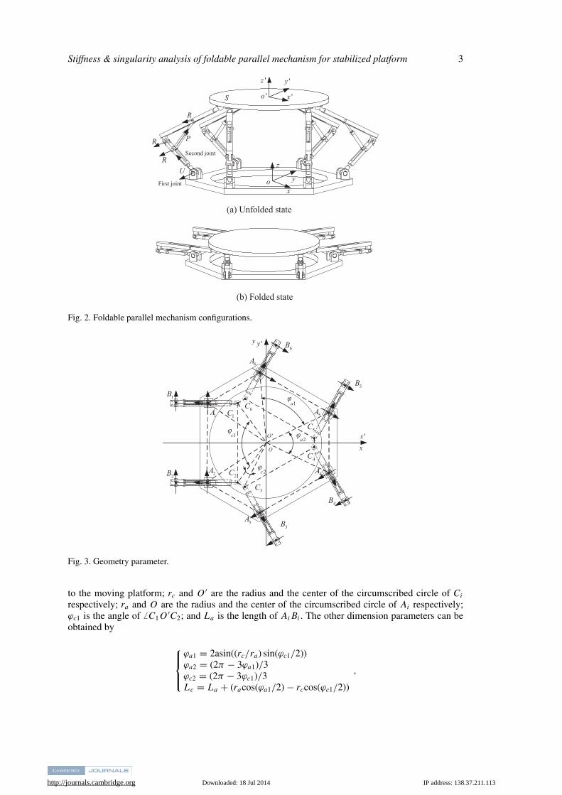
2.1. Description of mechanismsAs shown in Fig. 1, the movement of a ship is very complex as the wave in the sea is random. Theship’s movements are rolling, pitching, yawing, surging, swaying, and heaving. Therefore, it needs a6-DOF mechanism to isolate all these movements. In order to avoid the structural height restriction,the mechanisms are designed to be foldable. Figures 2(a) and (b) show the unfolded and folded statesrespectively. Meanwhile the closed chain drives are used to increase mechanism’s stiffness, as thelinear drives are easy to produce high stiffness by using screws. According to the closed chain, therotation of middle joint is driven by the translation drive, as shown in Fig. 2.
The mechanism contains six branches that are distributed regularly around the vertical axis ofa fixed platform. The axes (arrows on Ai (i = 1, 2 . . . 6)) of the U-joint’s first revolute joint isdistributed, as illustrated in Fig. 3. The axes of the U-joint’s second revolute joint points to the R-jointaxes and vertical to it, as shown in Fig. 2(a).
2.2. Inverse kinematicsThe sketch of a foldable parallel mechanism is illustrated in Fig. 3. Let Ai (i = 1, 2 . . . 6) denote thecentral point of the U-joint connected to a fixed platform; subscript i stands for the ith branch; Bi isthe center point of the joint between two bars; Ci is the center point of the sphere joint connected
http://journals.cambridge.org Downloaded: 18 Jul 2014 IP address: 138.37.211.113
Stiffness & singularity analysis of foldable parallel mechanism for stabilized platform 3
U
R
'x
'y'z
'o
xy
z
o
RSecond joint
First joint
R
P
S
(a) Unfolded state
(b) Folded state
Fig. 2. Foldable parallel mechanism configurations.
5A
x'x
4A
3A
2A
1A
6A
6B
φ
φφ
φ
5B
4B
3B
2B
1B
1C6C
2C
3C
4C
5C
1a
1c2a
O
'O
'yy
2c
Fig. 3. Geometry parameter.
to the moving platform; rc and O ′ are the radius and the center of the circumscribed circle of Ci
respectively; ra and O are the radius and the center of the circumscribed circle of Ai respectively;ϕc1 is the angle of � C1O
′C2; and La is the length of AiBi . The other dimension parameters can beobtained by
⎧⎪⎨⎪⎩
ϕa1 = 2asin((rc/ra) sin(ϕc1/2))ϕa2 = (2π − 3ϕa1)/3ϕc2 = (2π − 3ϕc1)/3Lc = La + (racos(ϕa1/2) − rccos(ϕc1/2))
,

http://journals.cambridge.org Downloaded: 18 Jul 2014 IP address: 138.37.211.113
4 Stiffness & singularity analysis of foldable parallel mechanism for stabilized platform
iaix
iyiz
Ci
iD
dL
iB
aL
iA
ilcl
al
iiB
θ
iE
iF
(a) (b)
Fig. 4. Branch and closed loop parameters.
where Lc is the length of BiCi ; ϕa1, ϕa2, and ϕc2 are the angles of � A5OC6, � A5OC4, and � C2O′C3
respectively.The ith branch coordinate frame {ai} is established on joint center Ai , as shown in Fig. 4. The
direction of the yi-axis coincides with the revolute joint axis. The zi-axis is vertical up.Let T denotes the homogenous representation of the moving platform frame {o′} relative to frame
{o}, T i is the transformation matrix of frame {ai} relative to frame {o}. The homogenous coordinatesof point Ci in terms of frame {ai} can be given by
Cai
i = [T i]−1 T Co′
i , (1)
where Co′i are the homogenous coordinates of point Ci in terms of frame {o′}.
Let Di be the projection of point Ci in the xizi-plane of frame {o}, the position vector of point Di
in terms of frame {ai} is given as
Dai
i =[ (
Cai
i
)xi
0(Cai
i
)zi
]T
,
where (Cai
i )xiand (Cai
i )ziare the components along the xi- and zi-axes of vector Cai
i respectively.The length of BiDi can be obtained from the result of Eq. (1),
Ld =(L2
c − (Cai
i
)2yi
)1/2, (2)
where, (Cai
i )yiis the component along the yi-axis of vector Cai
i .The following equations can be obtained based on the geometrical relationship
⎧⎨⎩
(Bai
i
)2xi
+ (Bai
i
)2zi
= L2a((
Bai
i
)xi
− (Dai
i
)xi
)2+
((Bai
i
)zi
− (Dai
i
)zi
)2= L2
d
. (3)
The above equations, combined with Eqs. (1) and (2), have two groups of solution. Since point Ci
is always in the positive direction of the z-axis of frame {o}, the projection of point Di should be inthe positive direction of the z-axis in terms of frame {ai}. Therefore, the rational solution of Eq. (3) isthe one which has a smaller (Bai
i )xi, and the homogeneous coordinates of point Bi can be represented
as
Bi = T i Bai
i .
The input angles θi (i = 1, 2, ...6) can be obtained from the above results. The rotation anglesof drive joints are determined by the input of prismatic joints in closed chain linkages, as shown
http://journals.cambridge.org Downloaded: 18 Jul 2014 IP address: 138.37.211.113
Stiffness & singularity analysis of foldable parallel mechanism for stabilized platform 5
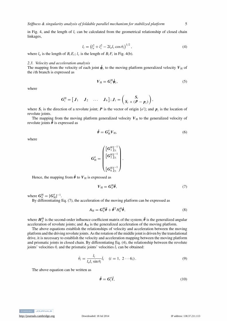
in Fig. 4, and the length of li can be calculated from the geometrical relationship of closed chainlinkages,
li = (l2a + l2
c − 2lalc cos θi
)1/2, (4)
where la is the length of BiEi ; lc is the length of BiFi in Fig. 4(b).
2.3. Velocity and acceleration analysisThe mapping from the velocity of each joint φi to the moving platform generalized velocity V H ofthe ith branch is expressed as
V H = GHi φi , (5)
where
GHi = [
J1 J2 . . . J6]
; J i =(
Si
Si × (P − pi)
),
where Si is the direction of a revolute joint; P is the vector of origin {o′}; and pi is the location ofrevolute joints.
The mapping from the moving platform generalized velocity V H to the generalized velocity ofrevolute joints θ is expressed as
θ = GθHV H, (6)
where
GθH =
⎛⎜⎜⎜⎜⎜⎝
[GH
1
]−1
3:[GH
2
]−1
3:
[GH
6
]−1
3:
⎞⎟⎟⎟⎟⎟⎠ .
Hence, the mapping from θ to V H is expressed as
V H = GHθ θ , (7)
where GHθ = [Gθ
H]−1.By differentiating Eq. (7), the acceleration of the moving platform can be expressed as
AH = GHθ θ + θTH H
θ θ , (8)
where HHθ is the second-order influence coefficient matrix of the system; θ is the generalized angular
acceleration of revolute joints; and AH is the generalized acceleration of the moving platform.The above equations establish the relationships of velocity and acceleration between the moving
platform and the driving revolute joints. As the rotation of the middle joint is driven by the translationaldrive, it is necessary to establish the velocity and acceleration mapping between the moving platformand prismatic joints in closed chain. By differentiating Eq. (4), the relationship between the revolutejoints’ velocities θi and the prismatic joints’ velocities li can be obtained:
θi = li
lalc sin θi
li (i = 1, 2 · · · 6;) . (9)
The above equation can be written as
θ = Gθl l, (10)
http://journals.cambridge.org Downloaded: 18 Jul 2014 IP address: 138.37.211.113
6 Stiffness & singularity analysis of foldable parallel mechanism for stabilized platform
where
Gθl = diag
(l1
lalc sin θ1
l2
lalc sin θ2· · · l6
lalc sin θ6
)6×6
.
According to Eqs. (7) and (10), the generalized velocity mapping of closed chain to the movingplatform can be obtained as,
V H = GHl l, (11)
where GHl = GH
θ Gθl is the first-order influence coefficient matrix of a foldable parallel mechanism
driven by closed chain.Similarly, the acceleration mapping from prismatic joints in closed chain linkages to the moving
platform can be built by differentiating Eq. (11),
AH = GHθ Gθ
l l + GHθ Gθ
l l + GHθ G
θ
l l. (12)
By differentiating Eqs. (9) and (10), the accelerations of revolute and prismatic joints have thefollowing relation:
θ = Gθl l + lT Hθ
l l, (13)
and the mapping of each branch:
θi = li
lalc sin θi
li + hi l2i , (14)
where
hi =lalc sin θi − l2
i
cos θi
sin θi
(lalc sin θi)2 .
Comparing with Eqs. (13) and (14), the second-order influence coefficient matrices of closed chainare obtained,
Hθl = diag
(h1 h2 · · · h6
)6×6×6 .
Substituting Eqs. (8), (10), and (13) into Eq. (12), the moving platform’s acceleration is given as,
AH = GHθ Gθ
l l + lT[Gθ
l
]THH
θ Gθl l + lT GH
θ ⊗ Hθl l,
where the symbol ⊗ represents the Kronecker product between matrices. The acceleration mappingof closed chain to the moving platform can be obtained as
AH = GHl l + lT HH
l l, (15)
where HHl = [Gθ
l ]T HHθ Gθ
l + GHθ ⊗ Hθ
l is the second-order influence coefficient matrix of thefoldable parallel mechanism driven by closed chain.
3. Directional Stiffness and its Extreme Value
3.1. Directional stiffnessTake 6-DOF mechanism for example, the only stiffness that we considered was the drive’s stiffnessk = diag(k1, k2, · · · k6), where ki is the stiffness of the ith branch drive. We also ignore the gravityand other forces acting on the link except the moving platform. Assume that the moving platform issuffering an external force FH, and the mechanism is in a state of equilibrium. After the force changes

http://journals.cambridge.org Downloaded: 18 Jul 2014 IP address: 138.37.211.113
Stiffness & singularity analysis of foldable parallel mechanism for stabilized platform 7
δFH = ( δMδF ), the mechanism will get into a state of new equilibrium. The generalized displacement of
the moving platform caused by the small force change is δT = ( δθ
δ p ), where δ p = [ δpx δpy δpz ]T
and δθ = [ δθx δθy δθz ]T.
By the principle of virtual work, we can get V TH FH + l
Tτ = 0, and then
lT
GHTl FH + l
Tτ = 0, (16)
where V H is the generalized velocity of the moving platform, l = [ l1 l2 · · · l6 ]T is thegeneralized velocity, and τ = [ τ1 τ2 · · · τ6 ]T is the drive force of the ith branch.
Eliminate lT
from Eq. (16), and derive both sides, then it can be written as,
δGHTl FH + GHT
l δFH + δτ = 0. (17)
By the definition of the second-order influence matrix, we get:
δGHTl FH =
6∑i=1
∂GHTl
∂liδli FH = (
HHTl ⊗ FH
)δl,
substitute it into Eq. (17), then
(HHT
l ⊗ FH)δl + GHT
l δFH + δτ = 0. (18)
As the drive stiffness is known as k = diag(k1, k2, · · · k6), we can get δτ = −kδl and δl =GH−1
l δT . Substitute these into Eq. (18), then we have:
δFH = (GHT
l
)−1 [k − (
HHTl ⊗ FH
)] (GH
l
)−1δT . (19)
So the stiffness matrix can be defined as
K = (GHT
l
)−1 [k − (
HHTq ⊗ FH
)] (GH
l
)−1. (20)
Set FH = 0, then the stiffness matrix is expressed as
K = (GHT
l
)−1k
(GH
l
)−1 = GlTH kGl
H . (21)
The compliance matrix is the inverse of the stiffness matrix:
C = GHl k−1GHT
l . (22)
Based on the above equation, the moving platform’s translational and rotational stiffness alongany direction can be deduced.
Assume the moving platform is suffering an external pure force without moment: δFH = ( 0δF ).
From Eq. (19), we can have
[0
δF
]=
[K 1 K 2
K 3 K 4
] [δθ
δ p
], (23)
where the stiffness matrix K is separated as four 3 × 3 matrix [ K 1 K 2K 3 K 4
].It should be noted here that in Eq. (23), δθ is not necessarily equal to zero, and δ p is not necessarily
be along δF either, for the translation of the moving platform caused by pure force may also couplewith some translation.
http://journals.cambridge.org Downloaded: 18 Jul 2014 IP address: 138.37.211.113
8 Stiffness & singularity analysis of foldable parallel mechanism for stabilized platform
Deduce Eq. (23) further:
{K 1δθ + K 2δ p = 0
K 3δθ + K 4δ p = δF.
Eliminating δθ above, we have
δF = (K 4 − K 3 K−1
1 K 2)δ p = Kpδ p. (24)
As the directions of δF and δ p are not coaxial, the projection of δ p on δF is the displacementchange along δF. The translational direction stiffness along δF, by symbol KF , can get
KF = |δF|2δ pTδF
= |δF|2δFT
(K−1
p
)TδF
. (25)
Setting δF = F f , f being the unit vector, Eq. (25) can be simplified as:
KF = f T K Tp f . (26)
In a similar way, assume the moving platform is suffering an external pure moment without forceδFH = ( δM
0 ), then we can get similar equation as Eq. (24):
δM = (K 1 − K 2 K−1
4 K 3)δθ = K θ δθ .
Then the rotational stiffness around δM can get:
KM = |δM|2δMT
(K−1
θ
)TδM
. (27)
Setting δM = Mm, m is the unit vector. The rotational stiffness around m can get
KM = mT K Tθ m. (28)
3.2. Extreme value of directional stiffnessTake translational stiffness, for example. In order to get the extreme stiffness when the direction fchanges, the Lagrange multiplier method is used:
L = f T K Tp f − λ
(f T f − 1
).
It should satisfy ∂L∂ f = 0; ∂L
∂λ= 0, when L reaches the extreme value,
{2 f T K T
p − 2λ f T = 0
f T f − 1 = 0.
Then we have Kp f = λ f and KF = f T K Tp f = λ, which means that all the eigenvalues of Kp
are the extreme values of translational stiffness, and the corresponding eigenvector is the direction.In the same way, the extreme value of rotational stiffness is all the eigenvalues of K θ , and the
corresponding eigenvector is the direction.

http://journals.cambridge.org Downloaded: 18 Jul 2014 IP address: 138.37.211.113
Stiffness & singularity analysis of foldable parallel mechanism for stabilized platform 9
Input T Inverse
kinematics Get H
iG
det ?Hi < ΔGSingularity
N
Get lθG
sin ?iθ < ΔY
Y
N
Get HlG
Get HθG
det ?Hθ < ΔG Singularity
N
Y
Singularity
Fig. 5. Flowchart of singularity judgment.
3.3. Singularity judgment analyzed by stiffnessSingularity is closely related to the Jacobian matrix. As illustrated in Eqs. (5) and (6), the inverse ofGH
i is necessary for building GHθ . Therefore, if the rank of GH
i is deficient, the branch is in singularity.Therefore, the parallel mechanism is apparently in singularity. If GH
i is not deficient, GHθ can be built.
However, if its rank is deficient, the mechanism is also in singularity. If Gθl cannot be calculated by
Eq. (10), then the branch is also in singularity, which causes the singularity of parallel mechanism.The judgments of singularity can be illustrated in Fig. 5. It should be noted that this method dependson the computer to calculate and judge nearly all the configurations in the workspace, and all thesingularity configurations are not absolutely precise but are very close to the singularities. is apositive real number that is close to zero.
The determinant of the first-order influence coefficient matrix is equal to zero when the mechanismis in a singular configuration. In practical applications, when the mechanism is near singularity, thekinematic performance may have already got poor. The singularities are classed into kinematicsingularity and constrained singularity based on causation. When the kinematic singularity occurs,kinematic screws get linear correlation and the moving platform cannot move along or around anydirection. Set the direction A(A �= 0), from GH
l l = V H we get GHl A = 0 and rankGH
l < 6. From Eq.(22), it satisfies rankC < 6, which means that the compliance along A, CA is zero, and the stiffnessalong A is infinite. When the constrained singularity occurs, constraint screws get linear correlationand the moving platform can achieve additional DOF along some directions when all the six drivesare locked. Set the direction B(B �= 0), considering l = Gl
HV H, we get GlH B = 0 and rankGl
H < 6.Considering Eq. (21), rankK < 6 can be obtained. It means that the stiffness along B, KB is zero.Both kinds of singularities may occur at the same position and orientation, and the difference is intheir directions.
4. ExamplesThe dimensions of the mechanism are set as rc = 1.75 m; ra = 2.5 m; ϕc1 = 110◦; La = 1.5 m; la =1.479 m; and lc = 1.479 m.
Spheroidal coordinate is used to illustrate the stiffness of moving platform in all directions. Itrepresents the direction and the norm of translational and rotational stiffness, shown in Figs. 6 and7. The distance from the points on the surface to the origin is the value of stiffness, and the vectors

http://journals.cambridge.org Downloaded: 18 Jul 2014 IP address: 138.37.211.113
10 Stiffness & singularity analysis of foldable parallel mechanism for stabilized platform
Fig. 6. The directional stiffness as the moving platform translates.
Fig. 7. The directional stiffness as the moving platform rotates.
of the points are the directions. The arrows in these figures illustrate extreme stiffness. As the maindestination is singularity analysis, it might as well set the drive stiffness as 1 N/m.
At the initial position and orientation (moving platform is in the middle place, and horizontal,the height is 2.5 m), the translational stiffness along all directions is illustrated in Fig. 6 (a). Itcan be seen that the distribution of translational stiffness is uniform. However, the distribution ofrotational stiffness is not uniform, especially when the stiffness around x ′, y ′ directions are smaller.The directional stiffness is illustrated in Fig. 6(b) and (c) when the moving platform moves 1 m and2.13 m (where it is very close to singularity) along the x ′-axis. As the mechanism gets close to theboundary of the workspace, it gets close to singularity as well, and the directional stiffness alongsome directions (such as P1) get close to infinite (200 times than the drive stiffness 1 N/m). Along

http://journals.cambridge.org Downloaded: 18 Jul 2014 IP address: 138.37.211.113
Stiffness & singularity analysis of foldable parallel mechanism for stabilized platform 11
(a) (b)
4P
oy
xz
'o
'y 'x'z'o
'y
'x'z1P
oy x
z
2P
3P
Fig. 8. The singularity configurations and the directions.
these directions the mechanism cannot move, which means kinematic singularity. On the other hand,along some directions, such as translational stiffness along P2 and rotational stiffness around P3, thevalue gets close to zero, and the mechanism loses its constraints, which means constrained singularity.Therefore, the configuration is in both kinematic and constrained singularity, and the difference isthe directions along (or around) which singularity occurs. The singularity configuration is shown inFig. 8 (a).
Figures 7(a), (b), and (c) illustrate the directional stiffness along and around the directions whenthe moving platform rotates 20◦, 35◦, and 50.3◦ around x ′ of {o′} coordinate respectively. It getsvery close to singularity when it rotates 50.3◦. The moving platform lost its constraints along somedirections, such as P4, for the stiffness along these directions is close to zero. The mechanism is inconstrained singularity only. The rotational stiffness changes are steady, and no singularity occursaround all these directions. The singularity configuration is shown in Fig. 8(b)
5. ConclusionsThe mechanism which is used as a heavy load ship-based stabilized platform has been analyzed.Based on inverse kinematics, the first- and second-order influence matrices of the closed loop drivemechanism have been deduced. The stiffness matrix considering changes in the configuration ofmechanism has been built based on virtual work principle. After that translational and rotationalstiffness along any directions are deduced. Moreover, the extreme values of translational and rotationalstiffness are obtained according to the separation of stiffness matrix. At last, the spheroidal coordinateswere used to illustrate directional stiffness. In this way, the singularity was analyzed using the dataof directional stiffness.
It is important that the way to analyze the singularity is visual and accessible. The directions canbe obtained to illustrate the directions the moving platform cannot move or lost its constraints. It willmake clear as to how the kinematic situation will be when the mechanism gets close to singularity.
AcknowledgmentThis work was supported by the National Natural Science Foundation of China (Grant Nos. 51375420and 51105322).
References1. J. A. Keller and E. C. Smith, “Experiment and theoretical correlation of helicopter rotor blade-droop stop
impacts,” J. Aircr. 36(2), 443–450 (1999).2. J. Ma, P. Yang and G. Li, “Simulation study of ship’s movement regularity and anti-rolling technology
under high-wave-level environment,” Ship Eng. 28(2), 24–29 (2006).3. M. M. Kamel, “Bifurcation analysis of a nonlinear coupled pitch-roll ship,” Math. Comput. Simul. 73(5),
300–308 (2007).4. Z. Huang, Y. S. Zhao and T. S. Zhao, Advanced Spatial Mechanism (Higher Education Press, Beijing,
China, 2006) pp. 169–212, 239–276.5. Z. Huang, L. F. Kong and Y. F. Fang, “Mechanism Theory and Control of Parallel Robot” (China Machine
Press, Beijing, China, 1997).

http://journals.cambridge.org Downloaded: 18 Jul 2014 IP address: 138.37.211.113
12 Stiffness & singularity analysis of foldable parallel mechanism for stabilized platform
6. B. Dasgupta and T. S. Mruthyunjaya, “Closed-form dynamic equations of the general Stewart platformthrough the Newton–Euler approach,” Mech. Mach. Theory 33(7), 993–1012 (1998).
7. T. Langbecker and F. Albermani, “Kinematic and non-linear analysis of foldable barrel vaults,” Eng. Struct.23, 158–171 (2001).
8. C. M. Gosselin and J. Angeles, “Singularity analysis of closed-loop kinematic chains,” IEEE Trans. Robot.Autom. 6(3), 281–290 (1990).
9. J. S. Zhao, J. Y. Wang, F. L. Chu and J. S. Dai, “Structure synthesis and statics analysis of a foldable stair,”Mech. Mach. Theory 46(7), 998–1015 (2011).
10. D. Zlatanov, R. G. Fenton and B. Benhabib, “A unifying framework for classification and interpretation ofmechanism singularities,” Trans. ASME J. Mech. Des. 117, 566–572 (1995).
11. D. Zlatanov, R. G. Fenton and B. Benhabib, “Identification and classification of the singular configurationsof mechanisms,” Mech. Mach. Theory 33(6), 743–760 (1998).
12. J. Chung, T. S. Jong, J. Y. Byung, K. K. Whee and H. L. Sang, “Implementation of a Foldable 3-DOFMaster Device to Handle a Large Glass Plate,” Proceedings of the IEEE/RSJ International Conference onIntelligent Robots and Systems, St. Louis, MO (2009) pp. 741–747.
13. J. Chung, J. Y. Byung and O. Sung, “A foldable 3-DOF parallel mechanism with application to a flat-panelTV mounting device,” IEEE Trans. Robot. 25(5), 1214–1221 (2009).
14. S. Joshi and L. W. Tsai, “A comparison study of two 3-DOF parallel manipulators: One with three and theother with four supporting legs,” IEEE Trans. Robot. Autom. 19(2), 200–209 (2003).
15. H. Shin, S. Kim, J. Jeong and J. Kim, “Stiffness enhancement of a redundantly actuated parallel machinetool by dual support rims,” Int. J. Precis. Eng. Manuf. 13(9), 1539–1547 (2012).
16. J. S. Dai and T. S. Zhao, “Stiffness characteristics and kinematics analysis of two-link elastic underactuatedmanipulators,” J. Robot. Syst. 19(4), 169–176 (2002).