Embed Size (px)
Citation preview
25 March 2009 NDC Business System R2Letterhead (scale 80%) Option #1
47533 Westinghouse Drive Fremont, California 94539 t 510.683.2000 f 510.683.2001
We are Nitinol.™
www.nitinol.com
ASurveyofStentDesigns
Stoeckel,Bonsignore,Duda
MinInvasTher&AlliedTechnol11(4)
pp.137‐147
2002
A Survey of Stent D.signs
D. Stoeckel', C. Bonsignore' and S. Duda'
1 Nitinol Devices & Components, Fremont. CA USA and lUniversity of TObingen. Dept of Diagnostic Radiology. TObingen
Summary
An estimated>' 00 different stent design are currently marketed or in evaluation for vascular and non-vascular indications. This paper attempts to differentiate stent designs by certain engineering aspects. A stent design pyramid is presented that breaks the differentiating aspects into materials, raw material forms, fabrication methods, geometrical features and additions. The primary distinguishing factor in all groups is balloon-expansion vs. self-expandability. Typical examples for each category of the pyramid are shown.
Keywords
Stents, materials, fabrication methods, geometrical features
Introduction
The 2000 "Handbook of Coronary Stents" edited by Serruys and Kurtryk [lllists 36 coronary stents or stent families, and "Koronarstenting" published in 2001 by Machraoui, Grewe and Fischer [2] brings the number of stents tabulated to 59. Neither book claims to be complete; each focuses on cardiology, excluding stents specifically marketed for peripheral or non-vascular indications. It is probably safe to assume that there are close to 100 different stents currently being marketed or in evaluation worldwide, with most of them available in Europe. Due to stricter FDA regulations, the number of approved stents in the USA is not quite as high, but still substantial. These stents compete for a market that is estimated to be near $3 billion and expected to double with the advent of drug eluting devices.
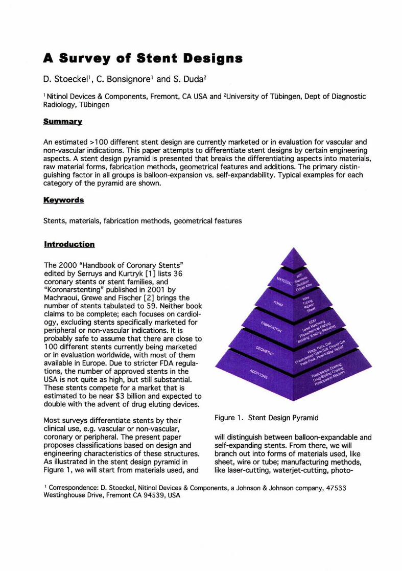
Most surveys differentiate stents by their clinical use, e.g. vascular or non-vascular, coronary or peripheral. The present paper proposes classifications based on design and engineering characteristics of these structures. As illustrated in the stent design pyramid in Figure 1, we will start from materials used, and
Figure 1. Stent Design Pyramid
will distinguish between balloon-expandable and self-expanding stents. From there, we will branch out into forms of materials used, like sheet, wire or tube; manufacturing methods, like laser-cutting, waterjet-cutting, photo-
1 Correspondence: D. Stoeckel, Nitinol Devices & Components, a Johnson & Johnson company, 47533 Westinghouse Drive, Fremont CA 94539, USA
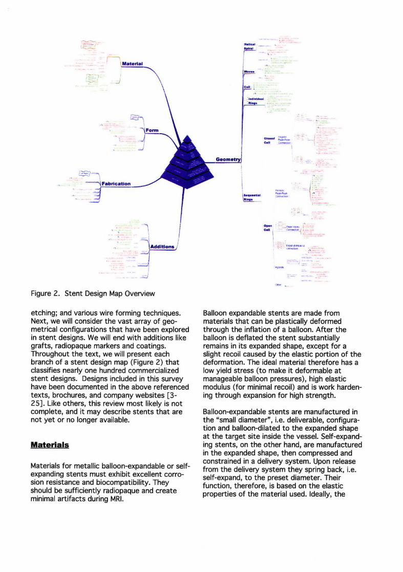
Figure 2. Stent Design Map Overview
etching; and various wire forming techniques. Next, we will consider the vast array of geometrical configurations that have been explored in stent designs. We will end with additions like grafts, radiopaque markers and coatings. Throughout the text, we will present each branch of a stent design map (Figure 2) that classifies nearly one hundred commercialized stent designs. Designs included in this survey have been documented in the above referenced texts, brochures, and company websites [3-25]. Like others, this review most likely is not complete, and it may describe stents that are not yet or no longer available.
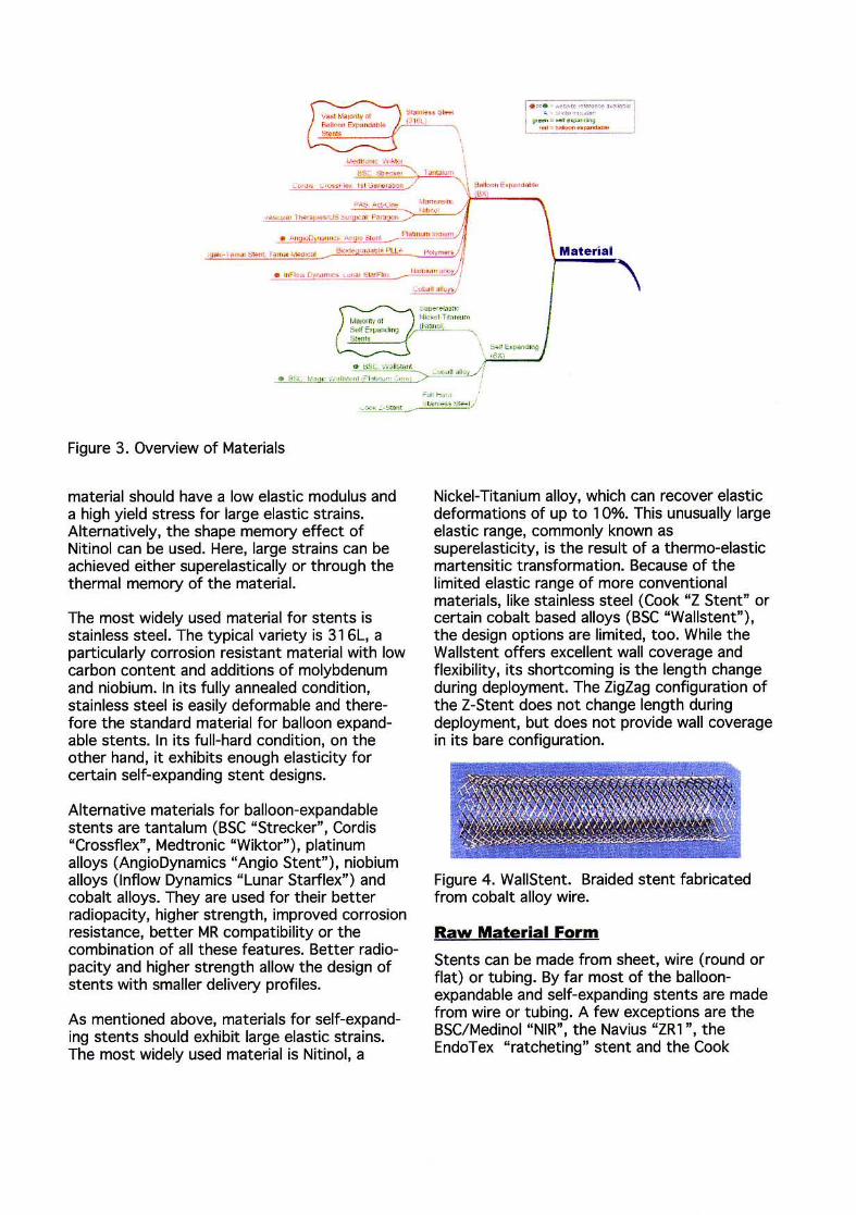
Materials
Materials for metallic balloon-expandable or selfexpanding stents must exhibit excellent corrosion resistance and biocompatibility. They should be sufficiently radiopaque and create minimal artifacts during MRI.
_.
~~
----- (.
- --- : c .. ! r __ ( : .;,_
I
Balloon expandable stents are made from materials that can be plastically deformed through the inflation of a balloon. After the balloon is deflated the stent substantially remains in its expanded shape, except for a slight recoil caused by the elastic portion of the deformation. The ideal material therefore has a low yield stress (to make it deformable at manageable balloon pressures), high elastic modulus (for minimal recoil) and is work hardening through expansion for high strength.
Balloon-expandable stents are manufactured in the "small diameter", i.e. deliverable, configuration and balloon-dilated to the expanded shape at the target site inside the vessel. Self-expanding stents, on the other hand, are manufactured in the expanded shape, then compressed and constrained in a delivery system. Upon release from the delivery system they spring back, i.e. self-expand, to the preset diameter. Their function, therefore, is based on the elastic properties of the material used. Ideally, the
I· "'· -...... ~,,· ...... I I "':" ':':''';:'~ I 1 ... · - - - _
Material
\
"~ H",' '.5'" _ ,~ ., ...... ri. """' j
Figure 3. Overview of Materials
material should have a low elastic modulus and a high yield stress for large elastic strains. Alternatively, the shape memory effect of Nitinol can be used. Here, large strains can be achieved either superelastically or through the thermal memory of the material.
The most widely used material for stents is stainless steel. The typical variety is 316L, a particularly corrosion resistant material with low carbon content and additions of molybdenum and niobium. In its fully annealed condition, stainless steel is easily deformable and therefore the standard material for balloon expandable stents. In its full-hard condition, on the other hand, it exhibits enough elasticity for certain self-expanding stent designs.
Alternative materials for balloon-expandable stents are tantalum (BSC "Strecker" , Cordis "Crossflex", Medtronic "Wiktor") , platinum alloys (AngioDynamics "Angio Stent"), niobium alloys (Inflow Dynamics "Lunar Starflex") and cobalt alloys. They are used for their better radiopacity, higher strength, improved corrosion resistance, better MR compatibility or the combination of all these features. Better radiopacity and higher strength allow the design of stents with smaller delivery profiles.
As mentioned above, materials for self-expanding stents should exhibit large elastic strains. The most widely used material is Nitinol, a
Nickel-Titanium alloy, which can recover elastic deformations of up to 1 0%. This unusually large elastic range, commonly known as superelasticity, is the result of a thermo-elastic martensitic transformation. Because of the limited elastic range of more conventional materials, like stainless steel (Cook "Z Stent" or certain cobalt based alloys (BSC "Wallstent" ), the design options are limited, too. While the Wallstent offers excellent wall coverage and flexibility, its shortcoming is the length change during deployment. The ZigZag configuration of the Z-Stent does not change length during deployment, but does not provide wall coverage in its bare configuration.
Figure 4. WaliStent. Braided stent fabricated from cobalt alloy wire.
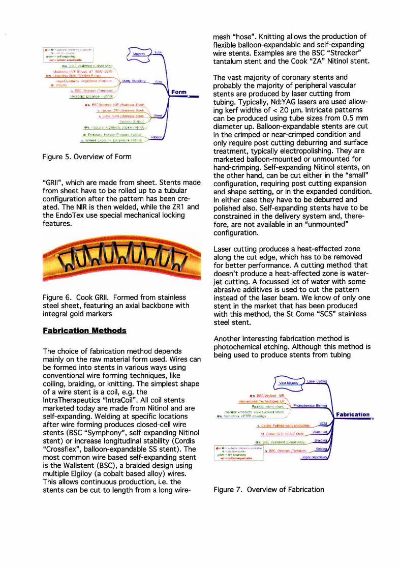
Raw Material Form
Stents can be made from sheet, wire (round or flat) or tubing. By far most of the balloonexpandable and self-expanding stents are made from wire or tubing. A few exceptions are the BSC/Medinol "NIR", the Navius "ZRl ", the EndoTex " ratcheting" stent and the Cook
I · "' · - ·-"~~~~-"" .. if _""'~
...-..... -~----. , pi , , " , .. -,. ... , ' "," : """!r ".
· ..... ,"'"'''·'F B"""" 6- "60< .'l6-0
. , f,SC'""""", ""1_ " "'" • r;~ . ,,,, : p" s.""""S ...... ' ~ ~,,:;+, G". ;,...,.. .. S, ... ' ' SO-
Figure 5. Overview of Form
"GRII", which are made from sheet. Stents made from sheet have to be rolled up to a tubular configuration after the pattern has been created. The NIR is then welded, while the ZRl and the EndoTex use special mechanical locking features.
Figure 6. Cook GRII. Formed from stainless steel sheet, featuring an axial backbone with integral gold markers
Fabrication Methods
The choice of fabrication method depends mainly on the raw material form used. Wires can be formed into stents in various ways using conventional wire forming techniques, like coiling, braiding, or knitting. The simplest shape of a wire stent is a coil, e.g. the lntraTherapeutics "lntraCoil" . All coil stents marketed today are made from Nitinol and are self-expanding. Welding at specific locations after wire forming produces closed-cell wire stents (BSC "Symphony" , self-expanding Nitinol stent) or increase longitudinal stability (Cordis "Crossllex". balloon-expandable SS stent). The most common wire based self-expanding stent is the Wallstent (BSC), a braided design using multiple Elgiloy (a cobalt based alloy) wires. This allows continuous production, i.e. the stents can be cut to length from a long wire-
mesh "hose". Knitting allows the production of flexible balloon-expandable and self-expanding wire stents. Examples are the BSC "Strecker" tantalum stent and the Cook "ZA" Nitinol stent.
The vast majority of coronary stents and probably the majority of peripheral vascular stents are produced by laser cutting from tubing. Typically, Nd:YAG lasers are used allowing kerf widths of < 20 !J.m. Intricate patterns can be produced using tube sizes from 0.5 mm diameter up. Balloon-expandable stents are cut in the crimped or near-crimped condition and only require post cutting deburring and surface treatment, typically electropolishing. They are marketed balloon-mounted or unmounted for hand-crimping. Self-expanding Nitinol stents, on the other hand, can be cut either in the "small" configuration, requiring post cutting expansion and shape setting, or in the expanded condition. In either case they have to be deburred and polished also. Self-expanding stents have to be constrained in the delivery system and, therefore, are not available in an "unmounted" configuration.
Laser cutting produces a heat-effected zone along the cut edge, which has to be removed for better performance. A cutting method that doesn't produce a heat-affected zone is waterjet cutting. A focussed jet of water with some abrasive additives is used to cut the pattern instead of the laser beam. We know of only one stent in the market that has been produced with this method, the St Come "SCS" stainless steel stent.
Another interesting fabrication method is photochemical etching. Although this method is being used to produce stents from tubing
L.o>o<Cv\ItfI
••• I . ,.. ' -..,., ..... "''' "-"'1 • ~ ."""," _'_. ~ as;:: i;>,,,,, ... T_, -......... H_ , i ... . __ I """ ,.on
Figure 7. Overview of Fabrication
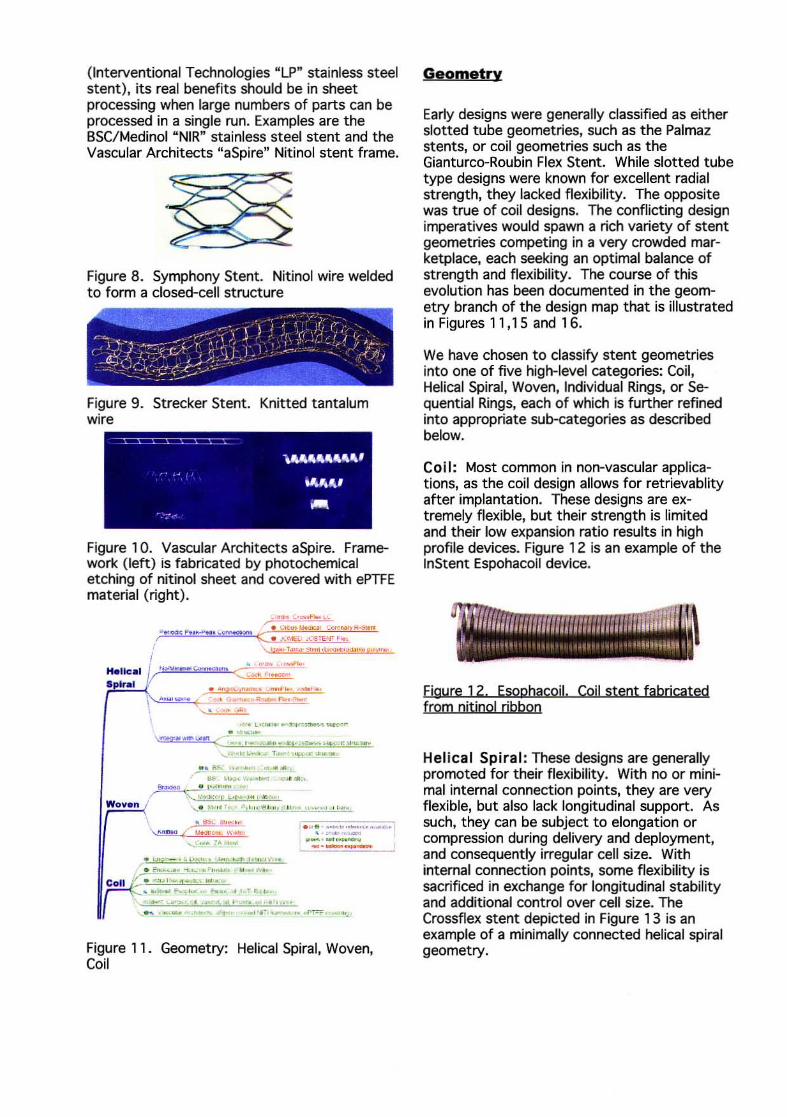
(lnterventional Technologies "LP" stainless steel stent), its real benefits should be in sheet processing when large numbers of parts can be processed in a single run. Examples are the BSC/Medinol "NIR" stainless steel stent and the Vascular Architects "aSpire" Nitinol stent frame.
Figure 8. Symphony Stent. Nitinol wire welded to form a closed-cell structure
Figure 9. Strecker Stent. Knitted tantalum wire
Figure 10. Vascular Architects aSpire. Framework (left) is fabricated by photochemical etching of nitinol sheet and covered with ePTFE material (right).
. .,..... ......... ~-..... , ....... ' , _. ,;_ .... _ .... -
.... L ....... O«<",-_ .. -,...." ....... "'''' (" ..• ,--", --~I';"""""": ~ .........
~ . ....... . , ...... .. ... , ... '. ~",,"''''''- ._-,
Bt_ _ I" '''' ''' / ~'"'2i '~o . '1" " "" .. . ..
'--. ""''' '~ ,,:! j , . ~~ ., .\ ,,,,....!...", _v,,,~
. !",,; lito", ...
\ ~....... ( tH.Ju, ... ...... ""
, . Fo ..... .. , .. ".' ...... , .... , ...
. ......... F-.. ..... "" •• ~'r~ . .. . ~ .- "'. -"- ' "' . " -"...... " ...... " .
' . ~. ' -, .. ,- ... ~-· I . """.,..-, , -_._--.--Moll • ~ .. " ..... .,-"", .. . . "
~ . .. . -.... ...... 'I .. P.·, ........ ~, _ ...
Figure 11. Geometry: Helical Spiral, Woven, Coil
Geometry
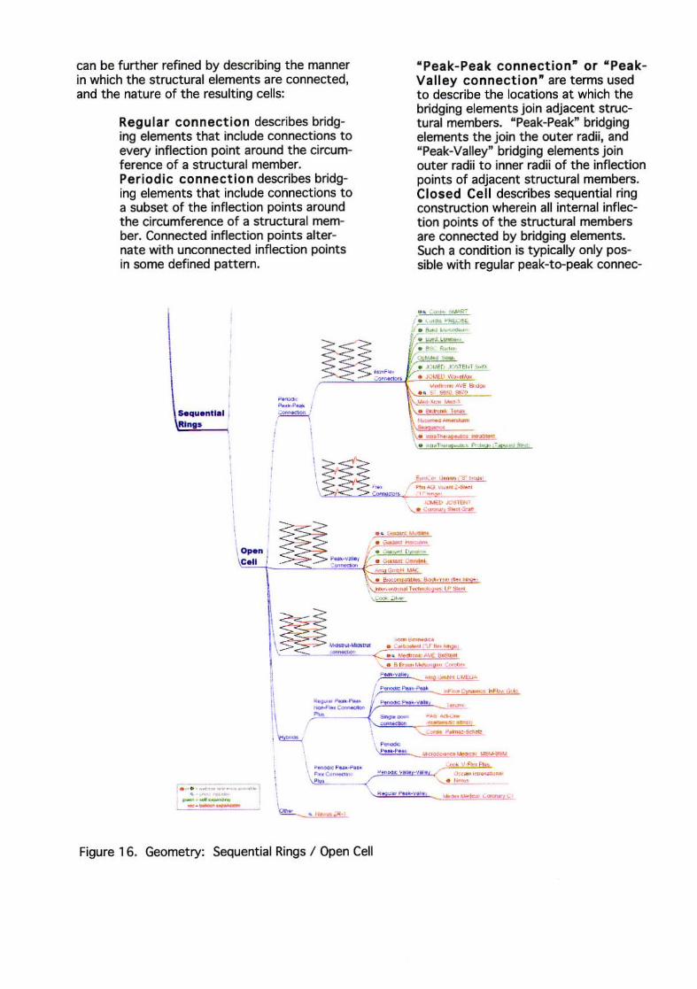
Early designs were generally classified as either slotted tube geometries, such as the Palmaz stents, or coil geometries such as the Gianturco-Roubin Flex Stent. While slotted tube type designs were known for excellent radial strength, they lacked flexibility. The opposite was true of coil designs. The conflicting design imperatives would spawn a rich variety of stent geometries competing in a very crowded marketplace, each seeking an optimal balance of strength and flexibility. The course of this evolution has been documented in the geometry branch of the design map that is illustrated in Figures 11,15 and 16.
We have chosen to classify stent geometries into one of five high-level categories: Coil, Helical Spiral, Woven, Individual Rings, or Sequential Rings, each of which is further refined into appropriate sub-categories as described below.
Coil: Most common in non-vascular applications, as the coil design allows for retrievablity after implantation. These designs are extremely flexible, but their strength is limited and their low expansion ratio results in high profile devices. Figure 12 is an example of the InStent Espohacoil device.
Figure 12. Esophacojl. Coil stent fabricated from nitinol ribbon
Helical Spiral: These designs are generally promoted for their flexibility. With no or minimal internal connection points, they are very flexible, but also lack longitudinal support. As such, they can be subject to elongation or compression during delivery and deployment, and consequently irregular cell size. With internal connection points, some flexibility is sacrificed in exchange for longitudinal stability and additional control over cell size. The Crossflex stent depicted in Figure 13 is an example of a minimally connected helical spiral geometry.

Figure 13. Crossflex. A minimally connected helical spiral stent fabricated from stainless steel wire
Woven: This category includes a variety of designs constructed from one or more strands of wire. Braided designs are often used for selfexpanding structures, such as the WallStent, as shown in Figure 4. While these designs offer excellent coverage, they typically shorten substantially during expansion. The radial strength of such a braided structure is also highly dependant on axial fixation of its ends. The Strecker stent (Figure 9) is an example of a balloon expandable knitted tantalum stent while the Cook ZA (Figure 14) stent demo~strates a self-expanding knitted Nitinol wire design.
Figure 14. Cook ZA. Knitted nitinol wire design featuring sleeve-type gold markers
Individual Rings: Single "z .. shaped rings are commonly used to support grafts or similar prostheses, as they can be individually sutured or otherwise attached to the graft material during manufacture. These structures are not typically used alone as vascular stents.
Sequential Rings: This category describes stents comprised of a series of expandable Z~~aped structural elements (known as "struts") JOined by connecting elements (known as "bridges", "hinges", or "nodes"). This type of construction accounts for the majority of commercially available stents and 70% of the designs included in this survey. This category
". ... " ' ....... ".l-~ •. lI< .. ' w ......... _ l"dlvkl~.I ' ',"e ~ .~. < •
Rlnliis V . .... ::"«"' .. ~...--.,.. "!'£Sf'"'''' '' " 'C<' , ( -.:.::,:."':"'----,-""' ..... ,-.-,.,. .' \"- '"- . ~ _ .",- ~ ...... ~, .. ".
" .. ,~-, .. ~ "", .... ..., ""' .. ~ \ ' ...... ,
I
!
" .~ :" ....... .... ,'" _.f", ' , w a "'" c......,,,.. ~ ~ ",", '.
• ., ~"..,._, • .IIl ~"" RvY~1. ' ''{ ' ''''''
I . c"' .. ~. ~ .. ~. ' .... • "',.. ....... H_ ... ~. 1<
.... .... ,..., ' ... ........,00 ' ""_ . "'" .. . 1 • . ,
""'-~~----, .... _o.-o u-_,_. \ . ... ' -C!!!!I!NI
--~ ...... - . ......... ..... / 0-" P\!II~ v
Figure 1 5. Geometry: Individual Rings, Sequential Rings / Closed Cell
can be further refined by describing the manner in which the structural elements are connected, and the nature of the resulting cells:
Regular connection describes bridging elements that include connections to every inflection point around the circumference of a structural member. Per iod ic connection describes bridging elements that include connections to a subset of the inflection points around the circumference of a structural member. Connected inflection points alternate with unconnected inflection points in some defined pattern.
--.~ ... I ,. .. ~. { , . 1
I -, --~ \~ .. " :os C.II . __ > ~"''''I ,-
- -<-
" Pea k- Peak connection- or " PeakValley connection" are terms used to describe the locations at which the bridging elements join adjacent structural members. "Peak-Peak" bridging elements the join the out er radii, and "Peak-Valley" bridging elements join outer radii to inner radii of the inflection points of adjacent structural members. Closed Cell describes sequential ring construction wherein all internal inflection points of the structural members are connected by bridging elements. Such a condition is typically only possible with regular peak-to-peak connec-
• . .. . . ., . _ JJ.<e
• , ..... .... ~ .. 1H I, . ",..., .~ .. __ _
-r .. """ ..-,T .....,..
. .... / """ «; ,~ .. tZ.eo_ ,',e
...,..,1> "'.'ENl \. . ........... _ <S'O!I
... _ .... -. ........ --l . ....... ..... , . . • ~o .-. - -"", ... ,
\"_._T_~
\.~ -.... -
\ ~~:$--- -_ . • ~ .. _ jV ... ""?~ - .. -',",, ~
\.. . & ....... .... "'"'11'" ~"' ''.'''
~
-.--_._-Figure 16. Geometry: Sequential Rings / Open Cell
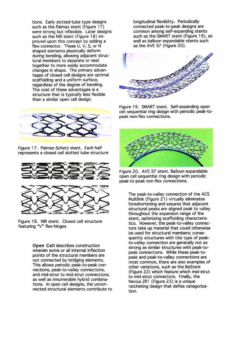
tions. Early slotted-tube type designs such as the Palmaz stent (Figure 17) were strong but inflexible. Later designs such as the NIR stent (Figure 18) improved upon this concept by adding a flex-connector. These U, V, S, or N shaped elements plastically deform during bending, allowing adjacent structural members to separate or nest together to more easily accommodate changes in shape. The primary advantages of closed cell designs are optimal scaffolding and a uniform surface, regardless of the degree of bending. The cost of these advantages is a structure that is typically less flexible than a similar open cell design.
Figure 17. Palmaz-Schatz stent. Each half represents a closed celt slotted tube structure
Figure 18. NIR stent. Closed cell structure featuring "V" flex-hinges
Open Cell describes construction wherein some or all internal inflection points of the structural members are not connected by bridging elements. This allows periodic peak-to-peak connections, peak-to-valley connections, and mid-strut to mid-strut connections, as well as innumerable hybrid combinations. In open cell designs, the unconnected structural elements contribute to
((
longitudinal flexibility. Periodically connected peak-to-peak designs are common among self-expanding stents such as the SMART stent (Figure 19), as well as balloon expandable stents such as the AVE 57 (Figure 20).
Figure 1 9. SMART stent. Self-expanding open cell sequential ring design with periodic peak-topeak non-flex connections.
Figure 20. AVE S7 stent. Balloon expandable open cell sequential ring design with periodic peak-to-peak non-flex connections.
The peak-to-valley connection of the ACS Multilink (Figure 21) virtually eliminates foreshortening and assures that adjacent structural peaks are aligned peak to valley throughout the expansion range of the stent, optimizing scaffolding characteristics. However, the peak-to-valley connectors take up material that could otherwise be used for structural members; consequently structures with this type of peakto-valley connection are generally not as strong as similar structures with peak-topeak connections. While these peak-topeak and peak-to-valley connections are most common, there are also examples of other variations, such as the BeStent (Figure 22) which feature which mid-strut to mid-strut connectors. Finally, the Navius ZRl (Figure 23) is a unique ratcheting design that defies categorization.
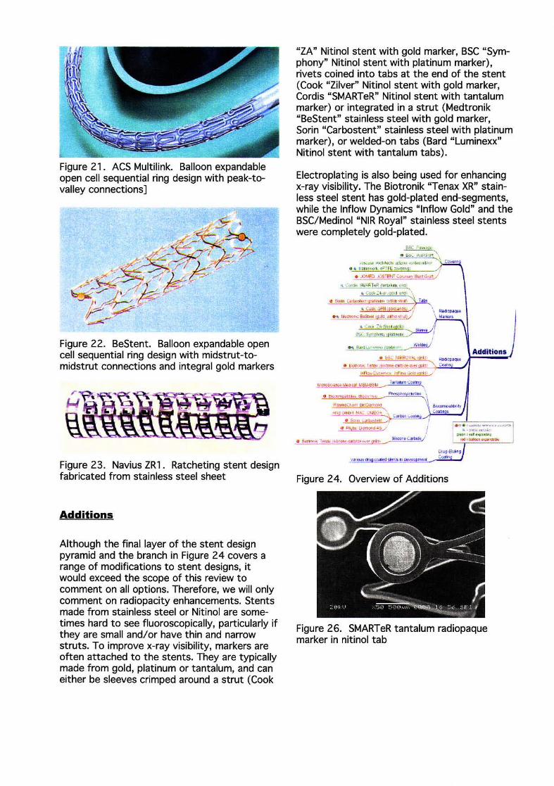
Figure 21. ACS Multilink. Balloon expandable open cell sequential ring design with peak-tovalley connections]
Figure 22. BeStent. Balloon expandable open cell sequential ring design with midstrut-tomidstrut connections and integral gold markers
Figure 23. Navius ZR1. Ratcheting stent design fabricated from stainless steel sheet
Additions
Although the final layer of the stent design pyramid and the branch in Figure 24 covers a range of modifications to stent designs, it would exceed the scope of this review to comment on all options. Therefore, we will only comment on radiopacity enhancements. Stents made from stainless steel or Nitinol are sometimes hard to see fluoroscopically, particularly if they are small and/or have thin and narrow struts. To improve x-ray visibility, markers are often attached to the stents. They are typically made from gold, platinum or tantalum, and can either be sleeves crimped around a strut (Cook
"ZA" Nitinol stent with gold marker, BSC "Symphony" Nitinol stent with platinum marker), rivets coined into tabs at the end of the stent (Cook "Zilver" Nitinol stent with gold marker, Cordis "SMARTeR" Nitinol stent with tantalum marker) or integrated in a strut (Medtronik "BeStent" stainless steel with gold marker, Sarin "Carbostent" stainless steel with platinum marker), or welded-on tabs (Bard "Luminexx" Nitinol stent with tantalum tabs).
Electroplating is also being used for enhancing x-ray visibility. The Biotronik "Tenax XR" stainless steel stent has gold-plated end-segments, while the Inflow Dynamics "Inflow Gold" and the BSC/Medinol "NIR Royal" stainless steel stents were completely gold-plated.
E-1C p. .... .; •
• """ "."-"r \ . -- , " ...... , - "'-..... ~~ , ......
• • "_~ ,O T r~ :o,,, "
~~~~I"""~ • _""' CO,., ',"-" .",', '\
. ..... c.,_ 'r_ ' " \",~",,, ,,~ , c=GRT! 'p1"'''!~' ~
• • '_a..-I2'I' . ...-"""] \ ... , .... ' • ~,' .• '-" ",. .. .. -10 ,
",""",'","~
... """,~ ,' c ...... • ,~ 00-'''''
Addit ions
• . -. .",* . .... ..... -• ~ 1 ..... ''''''_''''''''' ''''' P'' ___ iIoooi:<Nc....bo>Il ... . __
OI-.g ' E~J ''''''''''l'II ,- """'. ""'Y""'"' _ C:oo!:rj
Figure 24. Overview of Additions
Figure 26. SMARTeR tantalum radiopaque marker in nitinol tab
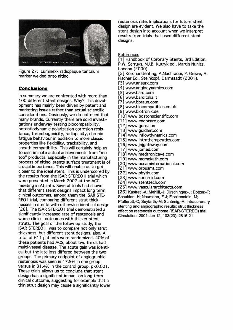
Figure 27. Luminexx radiopaque tantalum marker welded onto nitinol
Conclusions
In summary we are confronted with more than 1 00 different stent designs. Why? This development has mainly been driven by patent and marketing issues rather than actual scientific considerations. Obviously, we do not need that many brands. Currently there are solid investigations underway testing biocompatibility, potentiodynamic polarization corrosion resistance, thrombogenicity, radiopacity, chron~c fatigue behaviour in addition to more classIc properties like flexibility, trackability, and sheath compatibility. This will certainly help us to discriminate actual achievements from "me too" products. Especially in the manufacturing process of nitinol stents surface treatment is of crucial Importance. This will enable us to get closer to the ideal stent. This is underscored by the results from the ISAR STEREO II trial which were presented in March 2002 at the ACC meeting in Atlanta. Several trials had shown that different stent designs impact long term clinical outcomes, among them the ISAR STEREO I trial, comparing different strut thicknesses in stents with otherwise identical design [26]. The 15AR STEREO I trial demonstrated a significantly increased rate of restenosis and worse clinical outcomes with thicker stent struts. The goal of the follow up study, the ISAR STEREO II, was to compare not only strut thickness, but different stent designs, also. A total of 611 patients were randomized. 40% of these patients had ACS; about t wo thirds had multi-vessel disease. The acute gain was identical but the late loss differed between the two groups. The primary endpoint of angiographic restenosis was seen in 17.9% in one group versus in 31.4% in the control group, p<O.OOl. These trials allows us to conclude that stent design has a significant impact on long-term clinical outcome, suggesting for example that a thin strut design may cause a significantly lower
restenosis rate. Implications for future stent design are evident. We also have to take the stent design into account when we interpret results from trials that used different stent designs.
References [1] Handbook of Coronary Stents, 3rd Edition. P.W. Serruys, MJ.B. Kutryk ed., Martin Nunitz, London (2000). [2] Koronarstenting, A.Machraoui, P. Grewe, A. Fischer Ed., Steinkopf, Darmstadt (2001). [3] www.aneurx.com [4] www.angiodynamics.com [5] www.bard.com [6] www.barditalia.it [7] www.bbraun.com [8] www.biocompatibles.co.uk [9 ] www.biotronik.de [10] www.bostonscientific.com [11] www.endocare.com [12] www.gore.com [13] www.guidant.com [14] www.inflowdynamics.com [151 www.intratherapeutics.com [16] www.jnjgateway.com [17] www.jomed.com [18] www.medtronicave.com [19] www.memokath.com [20] www.occaminternational .com [211 www.orbusmt.com [22] www.phytis.com [23] www.sorin-cid.com [24] www.stenttech.com (25] www.vasculararchitects.com [26] Kastrati,-A; Mehilli,-J; Dirschinger,-J; Dotzer,-F; Schuhlen,-H; Neumann,-F-J; Fleckenstein,-M; Pfafferott,-C; Seyfarth,-M; Sch6mig,-A: Intracoronary stenting and angiographic results: strut thickness effect on restenosis outcome (ISAR-STEREO) trial. Circulation. 2001 Jun 12; 103(23): 2816-21


![Dra. Ana M. Bonsignore - SAPDra. Ana M. Bonsignore Title Microsoft PowerPoint - COLORADO 16.30 HS DRA. BONSIGNORE [Modo de compatibilidad] Author marianal Created Date 10/8/2019 4:38:20](https://img.pdfslide.net/doc/110x75/6123b2754c78b84e603fccdd/dra-ana-m-bonsignore-sap-dra-ana-m-bonsignore-title-microsoft-powerpoint-.jpg)


![La Invas[1][1]](https://img.pdfslide.net/doc/110x75/55d5d3f7bb61ebbf4f8b45e1/la-invas11.jpg)