Embed Size (px)
Citation preview
Storm Water Field Inspector’s Guide

Storm Water Field Inspector’s Guide
Texas Department of Transportation Environmental Affairs Division
118 East Riverside Drive Austin, Texas 78704
June 2004
Printed by:
TRC Environmental Corporation Austin, Texas
Printed on 20-lb. paper
June 2004
Published by:
Texas Department of Transportation Environmental Affairs Division
118 East Riverside Drive Austin, Texas 78704
Project Manager: Norm King Editor: Jesse Owens
Cover Design: Kari Means
Storm Water Field Inspector’s Guide
Table of Contents iii
TABLE OF CONTENTS
Page
INTRODUCTION ............................................................................................. 1 INTRODUCTION ............................................................................................... 2
Types of Best Management Practices ........................................................... 3 Inspection and Maintenance Guidelines ....................................................... 3
STORM WATER POLLUTION PREVENTION PLAN REQUIREMENTS............................................................................................. 5 STORM WATER POLLUTION PREVENTION PLAN REQUIREMENTS .... 7
Site Description ............................................................................................ 7 SW3P Description of Control Measures....................................................... 9 SW3P Stabilization Practices...................................................................... 10 SW3P Structural Practices .......................................................................... 10 SW3P Post-Construction Storm Water Management ................................. 10 Other Controls ............................................................................................ 11 Permit Requirement to Keep SW3P Current .............................................. 11 SW3P Signatory Requirements .................................................................. 12
INSPECTION FREQUENCY AND PROCEDURES .................................. 17 INSPECTION FREQUENCY AND PROCEDURES....................................... 19
Frequency ................................................................................................... 19 Record Keeping and General Procedures ................................................... 19
BEST MANAGEMENT PRACTICES— EROSION CONTROL.................................................................................... 25 TEMPORARY AND PERMANENT VEGETATION...................................... 26
Description.................................................................................................. 26 Inspection and Installation Guidelines........................................................ 26 Maintenance Guidelines ............................................................................. 26
MULCH............................................................................................................. 28 Description.................................................................................................. 28 Inspection and Installation Guidelines........................................................ 28 Maintenance Guidelines ............................................................................. 28
BLANKETS AND MATTINGS ....................................................................... 30 Description.................................................................................................. 30 Inspection and Installation Guidelines........................................................ 30 Maintenance Guidelines ............................................................................. 30
SODDING ......................................................................................................... 32 Description.................................................................................................. 32
Storm Water Field Inspector’s Guide
iv Table of Contents
TABLE OF CONTENTS (cont.)
Page Inspection and Installation Guidelines........................................................ 32 Maintenance Guidelines ............................................................................. 32
INTERCEPTOR AND PERIMETER SWALES............................................... 34 Description.................................................................................................. 34 Inspection and Installation Guidelines........................................................ 34 Maintenance Guidelines ............................................................................. 34
DIVERSION, INTERCEPTOR, AND PERIMETER DIKES........................... 36 Description.................................................................................................. 36 Inspection Guidelines ................................................................................. 36 Maintenance Guidelines ............................................................................. 36
STONE OUTLET STRUCTURES.................................................................... 38 Description.................................................................................................. 38 Inspection and Installation Guidelines........................................................ 38 Maintenance Guidelines ............................................................................. 38
PIPE SLOPE DRAIN ........................................................................................ 40 Description.................................................................................................. 40 Inspection and Installation Guidelines........................................................ 40 Maintenance Guidelines ............................................................................. 40
BEST MANAGEMENT PRACTICES— TEMPORARY SEDIMENT CONTROLS.................................................... 43 SANDBAG BERM............................................................................................ 44
Description.................................................................................................. 44 Inspection and Installation Guidelines........................................................ 44 Maintenance Guidelines ............................................................................. 44
SILT FENCE ..................................................................................................... 46 Description.................................................................................................. 46 Inspection and Installation Guidelines........................................................ 46 Maintenance Guidelines ............................................................................. 46
TEMPORARY EROSION CONTROL DEVICE ............................................. 48 Description.................................................................................................. 48 Inspection and Installation Guidelines........................................................ 48 Maintenance Guidelines ............................................................................. 48
TRIANGULAR FILTER DIKE......................................................................... 54 Description.................................................................................................. 54 Inspection and Installation Guidelines........................................................ 54 Maintenance Guidelines ............................................................................. 54
ROCK BERM.................................................................................................... 56
Storm Water Field Inspector’s Guide
Table of Contents v
TABLE OF CONTENTS (cont.)
Page Description.................................................................................................. 56 Inspection and Installation Guidelines........................................................ 56 Maintenance Guidelines ............................................................................. 56
HAY BALE DIKE............................................................................................. 58 Description.................................................................................................. 58 Inspection and Installation Guidelines........................................................ 58 Maintenance Guidelines ............................................................................. 58
STABILIZED CONSTRUCTION EXIT........................................................... 60 Description.................................................................................................. 60 Inspection and Installation Guidelines........................................................ 60 Maintenance Guidelines ............................................................................. 60
BRUSH BERM.................................................................................................. 62 Description.................................................................................................. 62 Inspection and Installation Guidelines........................................................ 62 Maintenance Guidelines ............................................................................. 62
SEDIMENT TRAP ............................................................................................ 64 Description.................................................................................................. 64 Inspection and Installation Guidelines........................................................ 64 Maintenance Guidelines ............................................................................. 64
SEDIMENT BASIN .......................................................................................... 66 Description.................................................................................................. 66 Inspection and Installation Guidelines........................................................ 66 Maintenance Guidelines ............................................................................. 66
BEST MANAGEMENT PRACTICES— PERMANENT SEDIMENT CONTROL ...................................................... 69 GRASSY SWALES........................................................................................... 70
Description.................................................................................................. 70 Inspection and Installation Guidelines........................................................ 70 Maintenance Guidelines ............................................................................. 70
RETENTION/IRRIGATION SYSTEMS.......................................................... 71 Description.................................................................................................. 71 Inspection and Installation Guidelines........................................................ 71 Maintenance Guidelines ............................................................................. 71
VEGETATIVE FILTER STRIPS...................................................................... 72 Description.................................................................................................. 72 Inspection and Installation Guidelines........................................................ 72 Maintenance Guidelines ............................................................................. 72
Storm Water Field Inspector’s Guide
vi Table of Contents
TABLE OF CONTENTS (cont.)
Page EXTENDED DETENTION BASIN.................................................................. 74
Description.................................................................................................. 74 Inspection and Installation Guidelines........................................................ 74 Maintenance Guidelines ............................................................................. 74
CONSTRUCTED WETLAND.......................................................................... 76 Description.................................................................................................. 76 Inspection and Installation Guidelines........................................................ 76 Maintenance Guidelines ............................................................................. 76
WET BASIN...................................................................................................... 78 Description.................................................................................................. 78 Inspection and Installation Guidelines........................................................ 78 Maintenance Guidelines ............................................................................. 78
SAND FILTER.................................................................................................. 80 Description.................................................................................................. 80 Inspection and Installation Guidelines........................................................ 80 Maintenance Guidelines ............................................................................. 80
OTHER BEST MANAGEMENT PRACTICES........................................... 83 GOOD HOUSEKEEPING................................................................................. 84 CONSTRUCTION WASTES............................................................................ 85 HAZARDOUS MATERIALS ........................................................................... 86 OFF-SITE VEHICLE TRACKING................................................................... 88 SANITARY FACILITIES ................................................................................. 89 SPILLS .............................................................................................................. 90 TXDOT SPECIFICATIONS AND DRAWINGS.......................................... 91 TXDOT SPECIFICATIONS AND DRAWINGS ............................................. 93 REFERENCES................................................................................................. 95 REFERENCES .................................................................................................. 97
Storm Water Field Inspector’s Guide
Table of Contents vii
LIST OF FIGURES
Page Figure 1. SW3P Checklist ............................................................................... 13 Figure 2. Form 2118........................................................................................ 21 Figure 3. Temporary and Permanent Vegetative Cover .................................. 27 Figure 4. Anchoring of Blankets and Mattings ............................................... 31 Figure 5. Sod Installation Techniques ............................................................. 33 Figure 6. Interceptor and Perimeter Swales..................................................... 35 Figure 7. Diversion, Interceptor, and Perimeter Dikes .................................... 37 Figure 8. Stone Outlet Structures Installed with a Sediment Trap .................. 39 Figure 9. Pipe Slope Drain Installation ........................................................... 41 Figure 10. Sandbag Berm Installation ............................................................... 45 Figure 11. Silt Fence Installation....................................................................... 47 Figure 12. Temporary Erosion-Control Device—Filter Logs and Diameters ... 49 Figure 13. Temporary Erosion-Control Device—Back of Curb ....................... 50 Figure 14. Temporary Erosion-Control Device—Edge of Right-of-Way ......... 51 Figure 15. Temporary Erosion-Control Device—Check Dam.......................... 52 Figure 16. Temporary Erosion-Control Devices ............................................... 53 Figure 17. Triangular Filter Dike Installation ................................................... 55 Figure 18. Rock Berm Installation at the Toe of a Slope .................................. 57 Figure 19. Hay Bale Dike Installation ............................................................... 59 Figure 20. Stabilized Construction Exit—Plan and Profile............................... 61 Figure 21. Brush Berm Installation ................................................................... 63 Figure 22. Sediment Trap Installation ............................................................... 65 Figure 23. Sediment Basin Installation.............................................................. 67 Figure 24. Vegetative Filter Strip...................................................................... 73 Figure 25. Extended Detention Basin—Plan and Profile .................................. 75 Figure 26. Constructed Wetland—Plan and Profile .......................................... 77 Figure 27. Wet Basin—Plan and Profile ........................................................... 79 Figure 28. Sand Filter—Plan and Profile .......................................................... 81
LIST OF TABLES
Page Table 1. Mulch Types .................................................................................... 29

Storm Water Field Inspector’s Guide
Introduction 1
INTRODUCTION
Storm Water Field Inspector’s Guide
2 Introduction
INTRODUCTION
Construction activities can be a major cause of water pollution. Polluted storm water from construction sites is often conveyed via storm sewer systems into rivers and streams. Anywhere soil-disturbing activities occur, erosion and sedimentation are potential problems. Soil-disturbing activities increase the potential for storm water runoff pollution, which can cause downstream impacts to receiving waters. Sediment from construction sites has been shown to exceed that from agricultural land by 10 to 20 times, and by 1,000 to 2,000 times for forested land. In addition to soil-disturbing activities, poor construction management practices, including waste and spill control, can impact receiving waters. As part of an ongoing effort to minimize and/or eliminate pollution to receiving waters, the Texas Department of Transportation (TxDOT) continually evaluates and implements procedures and practices related to storm water runoff pollution. TxDOT’s goal is to prevent the pollution of storm water runoff from highway projects, particularly construction-related activities.
To facilitate this objective of reducing storm water pollution, TxDOT has created this Storm Water Field Inspector’s Guide. The purpose of this guide is to assist TxDOT field inspectors in ensuring compliance with the Texas Commission on Environmental Quality (TCEQ) and Environmental Protection Agency (EPA) Construction General Permit (CGP) conditions for construction projects. This guide also is designed to compliment TxDOT’s Storm Water Management Guidelines for Construction Activities document. Unless otherwise noted, all figures within this guide are from the Storm Water Management Guidelines for Construction Activities document.
For construction activities, TxDOT implements best management practices (BMPs) for compliance with applicable regulations. BMPs are required for construction areas at which final soil stabilization is not established. For each implemented BMP, an inspection and maintenance program is required to ensure that the BMP is functioning as designed. This inspection guide provides a listing of BMPs and the associated inspection and maintenance activities, as summarized below. TxDOT specifications take precedent over this guidance document.
Storm Water Field Inspector’s Guide
Introduction 3
Types of Best Management Practices BMPs are procedures, devices, and practices that are implemented to minimize and/or eliminate erosion, sedimentation, and the introduction of other pollutants to storm water. TxDOT, the EPA, and the TCEQ have developed BMPs based on previous efforts that are approved for use at highway construction sites. Erosion control BMPs are implemented to reduce erosion of the surface cover, including limiting disturbance to native vegetation. By reducing erosion, sediment transport is minimized. Once sediment becomes mobile, sediment-control BMPs are required to reduce the volume of sediment being transported off-site. TxDOT’s goal is to prevent all silt and sediment from entering creeks, rivers, and marshes. The most common sediment-control BMPs slow down storm water flow, letting the dirt settle out. Other BMPs actually catch the dirt, like the oil filter in your truck.
While sediment- and erosion-derived pollutants are the most common at construction sites, other pollutants can have an impact on storm water. Other pollutants are caused by poor housekeeping procedures, poor waste management practices, and other management activities.
Following this introduction, this document addresses erosion, sediment, and other pollutant categories of management practices. Within each section, specific, approved BMPs are detailed and the installation and maintenance requirements are provided.
Inspection and Maintenance Guidelines For each BMP described in this document, a description of the activity and inspection and maintenance guidelines are provided. The inspection subsection is intended to provide detailed inspection procedures for activities that occur during the construction phase of the project. The BMP maintenance subsection provides maintenance procedures for activities conducted after construction is complete but for which permanent erosion and sediment controls have not yet been established.
Many of the BMP activities associated with construction inspection are also required during the maintenance phase of the project. The maintenance subsection summarizes maintenance activities that are detailed in the construction inspection subsection.


Storm Water Field Inspector’s Guide
SW3P Requirements 5
STORM WATER POLLUTION PREVENTION PLAN
REQUIREMENTS

Storm Water Field Inspector’s Guide
SW3P Requirements 7
STORM WATER POLLUTION PREVENTION PLAN REQUIREMENTS
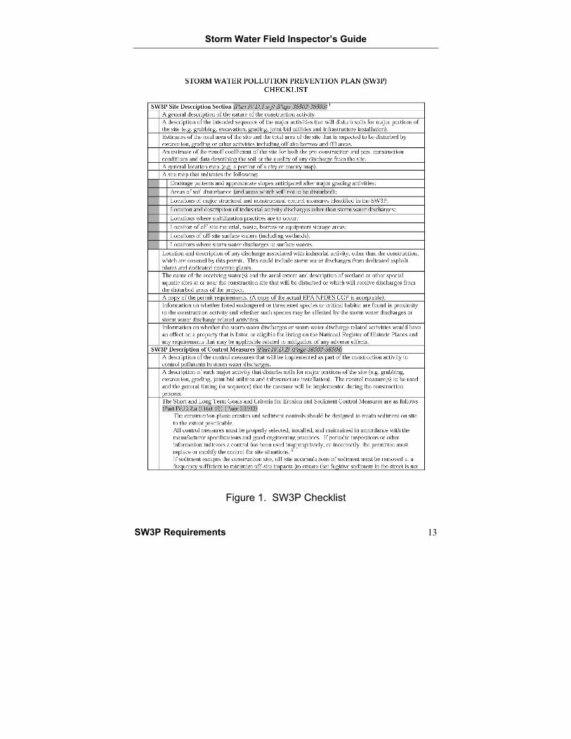
A Storm Water Pollution Prevention Plan (SW3P) is prepared to provide planning and design for environmental protection controls and to ensure minimal environmental impact during highway construction projects. The following sections outline the contents of the SW3P. A checklist of the information required in the SW3P is shown in Figure 1.
The SW3P should be developed jointly by the District Hydraulic Engineer, the TPD Environmental Coordinator, and the District Environmental Quality Control (DEQC). Controls developed in the SW3P should work at the site; if they do not work, the controls and the SW3P must be fixed. The key sections of the SW3P are as follows.
Site Description A general description of the type of construction activity.
A description of potential pollutants and sources.
A description of the sequence of major activities that will disturb soil at major portions of the site (e.g., grubbing, excavation, grading, joint-bid utilities, and infrastructure installation).
Estimates of the total area of the site. The contract defines all TxDOT sites within the project, whether at one location (typical linear roadway construction project) or multiple locations (off-system bridges at multiple locations). Estimates of the total area of the site to be disturbed by excavation, grading, or other activities, including off-site borrow and fill areas. For a project involving multiple locations and SW3Ps, add the total disturbed area shown on each SW3P to determine the project’s total disturbed area.
An estimate of the site runoff coefficient before and after construction.
Data describing the soil or the quality of any discharges from the site.
A general location map (e.g., a portion of a city or county map).
Storm Water Field Inspector’s Guide
8 SW3P Requirements
Site map with the following:
• Drainage patterns and slopes expected after major grading activities
• Areas where soil is and is not disturbed
• Locations of major control measures identified in the SW3P
• Locations where stabilization practices will occur
• Locations of off-site material, waste, borrow, or equipment storage areas
• Locations of off-site surface waters (including wetlands)
• Locations where storm water discharges to surface waters
Location and description of any discharge associated with industrial activity, other than the construction, covered under the site permit. This could include storm water discharges from dedicated asphalt plants and dedicated concrete plants.
The name of the receiving water(s) and the extent and description of wetland or other special aquatic sites at or near the construction site that will be disturbed or that will receive discharges from the disturbed areas of the project.
A copy of the permit requirements. A copy of the Texas Pollutant Discharge Elimination System (TPDES) CGP is acceptable, if applicable.
Information on whether or not endangered or threatened species or critical habitat are found near the construction activities and whether or not the species may be affected by the storm water discharges or related activities.
Information on whether or not the storm water discharges or related activities would have an effect on a property that is listed or eligible for listing on the National Register of Historic Places and any applicable requirements to reduce adverse effects.
Storm Water Field Inspector’s Guide
SW3P Requirements 9
SW3P Description of Control Measures Measures will be implemented as part of construction activities to control pollutants in storm water discharges. The SW3P will provide information on these control measures, which will include the following:
• A description of the control measures
• A description of each major activity that disturbs soil at major portions of the site (e.g., grubbing, excavation, grading, joint-bid utilities, and infrastructure installation)
• The general timing/sequence the control measure will be implemented during the construction process
Short- and Long-Term Goals and Criteria for Erosion and Sediment Control Measures are as follows:
• Controls should be designed to keep sediment on-site to the maximum extent possible.
• Control measures must be properly selected, installed, and maintained.
• If periodic inspections or other information indicates that a control has been used inappropriately or incorrectly, the control must be replaced or modified for site situations.
• If sediment escapes the construction site, off-site buildup of sediment must be removed often enough to minimize off-site impacts. Timing of buildup removal must ensure that sediment in the street is not washed into storm sewers by the next rain event and/or does not pose a safety hazard to users of public streets.
• Sediment must be removed from sediment controls when capacity has been reduced by 50%. For example, sediment should be removed from a silt fence when the silt has reached 50% of the fence height.
Storm Water Field Inspector’s Guide
10 SW3P Requirements
• Litter, construction debris, and construction chemicals exposed to storm water shall be prevented from polluting storm water discharges For example, outfall can be screened and trash can be picked up daily.
• Off-site material storage areas (including dirt overburden and stockpiles, borrow areas, etc.) used solely by the project are to be addressed in the SW3P.
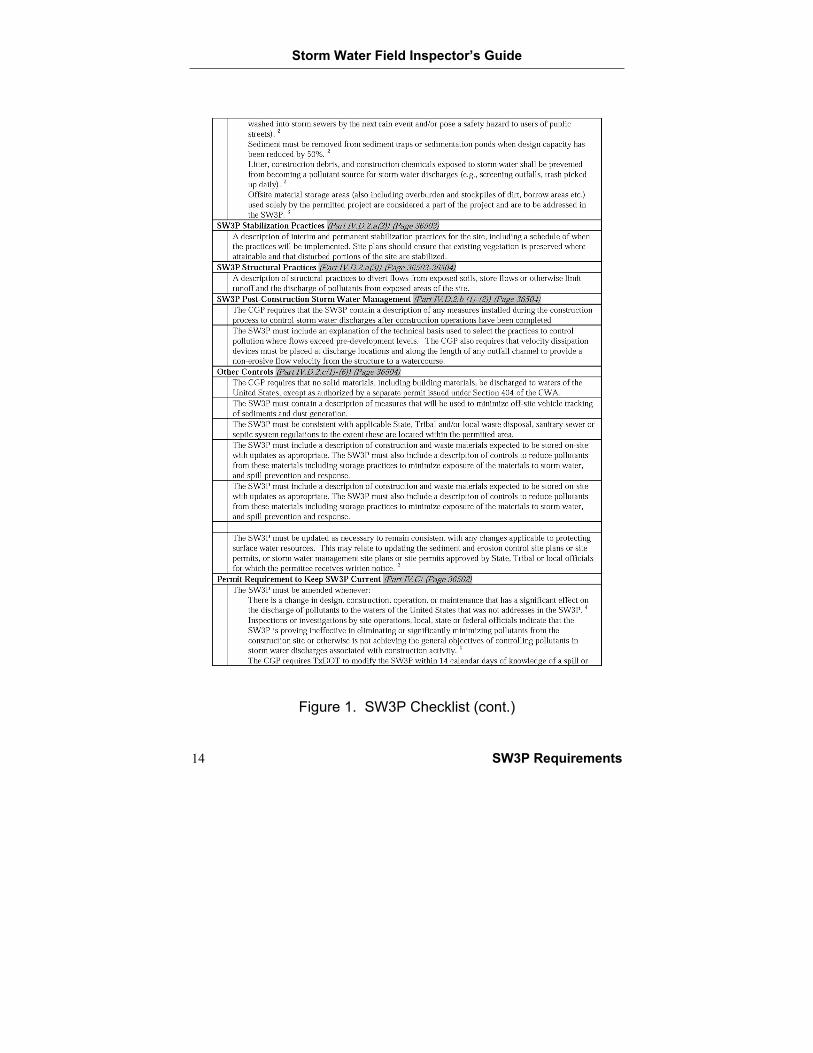
SW3P Stabilization Practices A description of temporary and permanent stabilization practices for the site, including a schedule of when the practices will be implemented.
Site plans should ensure that existing vegetation is not disturbed, if possible, and that disturbed portions of the site are stabilized.
SW3P Structural Practices A description of structural practices to reroute flow from exposed soil, store flow, or otherwise limit runoff and the discharge of pollutants from exposed areas of the site.
SW3P Post-Construction Storm Water Management The CGP requires that the SW3P contain a description of any measures installed during the construction process to control storm water discharges after construction operations have been completed.
The SW3P must include an explanation of the technical reasons for selecting practices to control pollution where flows are greater than pre-development levels. The CGP also requires that velocity-reducing devices be placed at discharge locations and along the length of any outfall channel to provide a flow velocity that prevents erosion from the structure to a watercourse.
Storm Water Field Inspector’s Guide
SW3P Requirements 11
Other Controls The CGP requires that no solid materials, including building materials, be discharged to receiving waters unless specially authorized. The SW3P must contain a description of measures to minimize off-site vehicle tracking of sediments and dust generation. See the Other Best Management Practices section of this document for further information.
The SW3P must be consistent with applicable state, Tribal, and/or local waste disposal, sanitary sewer, or septic system regulations to the extent that these are located within the permitted area.
The SW3P must include a description of construction and waste materials expected to be stored on-site, with updates as appropriate. The SW3P must also include a description of controls to reduce pollutants from these materials, including storage practices to minimize exposure of the materials to storm water and spill prevention and response. See the Other Best Management Practices section of this document for further information.
The SW3P must be updated to remain consistent with any changes applicable to protecting surface water resources. This may relate to updating the sediment- and erosion-control site plans or site permits, storm water management site plans, or site permits approved by state, Tribal, or local officials as requested by written notice.
Permit Requirement to Keep SW3P Current The TxDOT construction inspector and the contractor superintendent must work together to identify any changes in the SW3P. The TxDOT construction inspector must provide the project engineer and Area Engineer (AE) with constant feedback if the SW3P is current.
The SW3P must be amended whenever:
• There is any change in design, construction, operation, or maintenance that has an effect on the discharge of pollutants to receiving waters that was not addressed in the SW3P.
Storm Water Field Inspector’s Guide
12 SW3P Requirements
• Inspections by site operations, local, state, or federal officials indicate that the SW3P is ineffective in eliminating or significantly minimizing pollutants from the construction site or otherwise is not achieving the general objectives of controlling pollutants in storm water discharges.
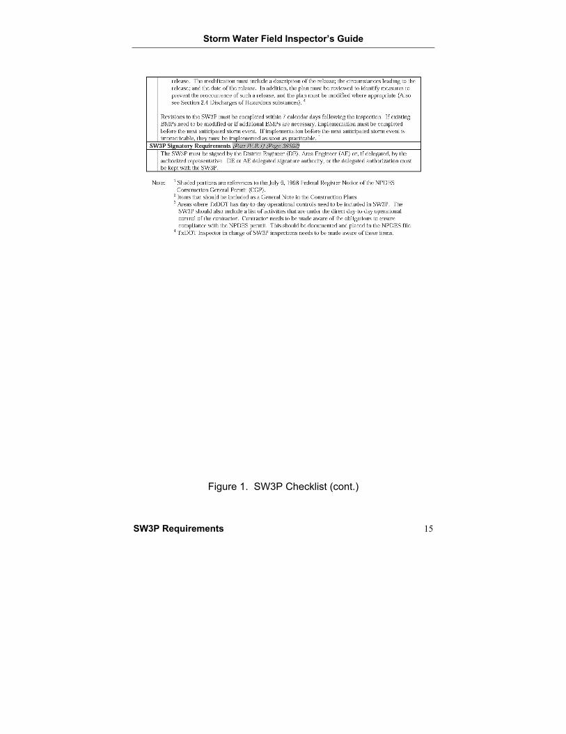
• The CGP requires TxDOT to modify the SW3P within 14 calendar days of a spill or release. The modification must include a description of the release, the circumstances leading to the release, and the date of release. The plan must be reviewed to identify measures to prevent the event of such a release, and the plan must be modified where appropriate.
SW3P Signatory Requirements The SW3P must be signed by the District Engineer (DE), AE, or, if delegated, the authorized representative. DE- or AE-delegated signature authority, or the delegated authorization, must be kept with the SW3P.
Storm Water Field Inspector’s Guide
SW3P Requirements 13
Figure 1. SW3P Checklist
Storm Water Field Inspector’s Guide
14 SW3P Requirements
Figure 1. SW3P Checklist (cont.)
Storm Water Field Inspector’s Guide
SW3P Requirements 15
Figure 1. SW3P Checklist (cont.)


Storm Water Field Inspector’s Guide
Inspection Procedures 17
INSPECTION FREQUENCY AND PROCEDURES

Storm Water Field Inspector’s Guide
Inspection Procedures 19
INSPECTION FREQUENCY AND PROCEDURES
Frequency Qualified personnel should inspect the construction site on a regular inspection cycle. Inspection cycles include at least once every 14 calendar days and within 24 hours of the end of a rainfall that is 1/2-inch or greater or once every 7 days. Where sites have been finally stabilized, or during seasonal arid periods in arid (with an average annual rainfall of 0 to 10 inches) and semiarid (with an average annual rainfall of 10 to 20 inches) areas, inspections shall be conducted at least monthly. The inspection cycle is located on the project’s SW3P sheet. The default option is at least once every 14 calendar days and within 24 hours of the end of a rainfall that is 1/2 inch or greater. The inspection shall include an evaluation of the BMP condition, maintenance requirements, and an indication of whether or not the device is functioning properly. If the inspection determines that modifications to the SW3P are needed, changes will be completed within 7 calendar days of the inspection.
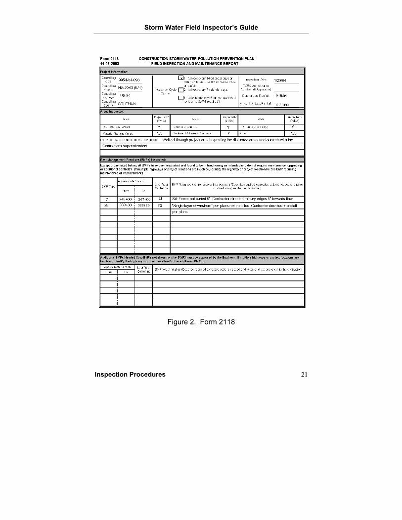
Record Keeping and General Procedures A report summarizing the inspection shall be completed that includes the following:
• Name(s) and qualifications of personnel making the inspection
• The date(s) of the inspection
• Major observations relating to the implementation of the SW3P and actions taken.
The inspection form to be used—Form 2118—is presented in Figure 2.
Note: The Engineer must approve additional BMPs identified as needed in an inspection that is not shown on the SWP3.
If any issues are listed that are potentially not in compliance, forward the report immediately to your supervisor. Corrective actions must be taken immediately when the contractor or cleanup procedure is not in compliance with BMPs.
Storm Water Field Inspector’s Guide
20 Inspection Procedures
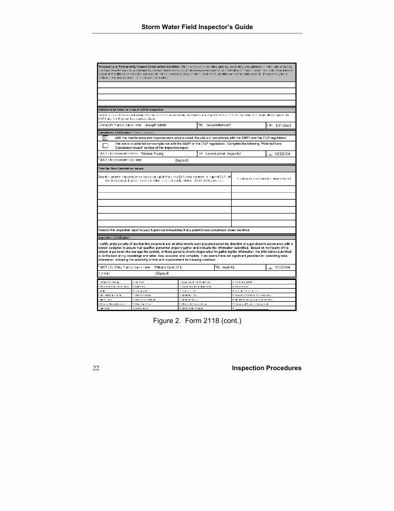
The inspection form certification can be signed by the DE, Division Director, or their immediate staff; AEs; Assistant AEs; Maintenance Supervisors; Project Architects or Engineers; or Project Inspectors with overall responsibility for the project.
Records of all inspections shall be retained on-site.
Storm Water Field Inspector’s Guide
Inspection Procedures 21
Figure 2. Form 2118
Storm Water Field Inspector’s Guide
22 Inspection Procedures
Figure 2. Form 2118 (cont.)
Storm Water Field Inspector’s Guide
Inspection Procedures 23
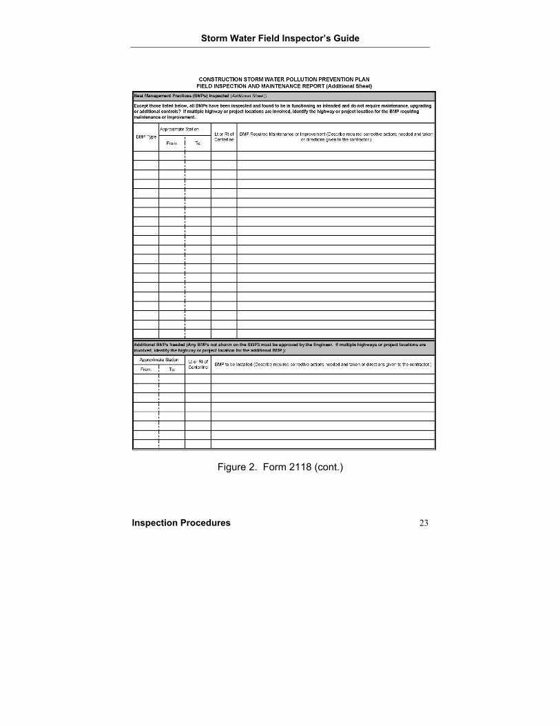
Figure 2. Form 2118 (cont.)


Storm Water Field Inspector’s Guide
Erosion Control 25
BEST MANAGEMENT PRACTICES— EROSION CONTROL
Temporary and Permanent Vegetation
Mulch
Blankets and Mattings
Sodding
Interceptor and Perimeter Swales
Diversion, Interceptor, and Perimeter Dikes
Stone Outlet Structures
Pipe Slope Drain
Storm Water Field Inspector’s Guide
26 Erosion Control
TEMPORARY AND PERMANENT VEGETATION
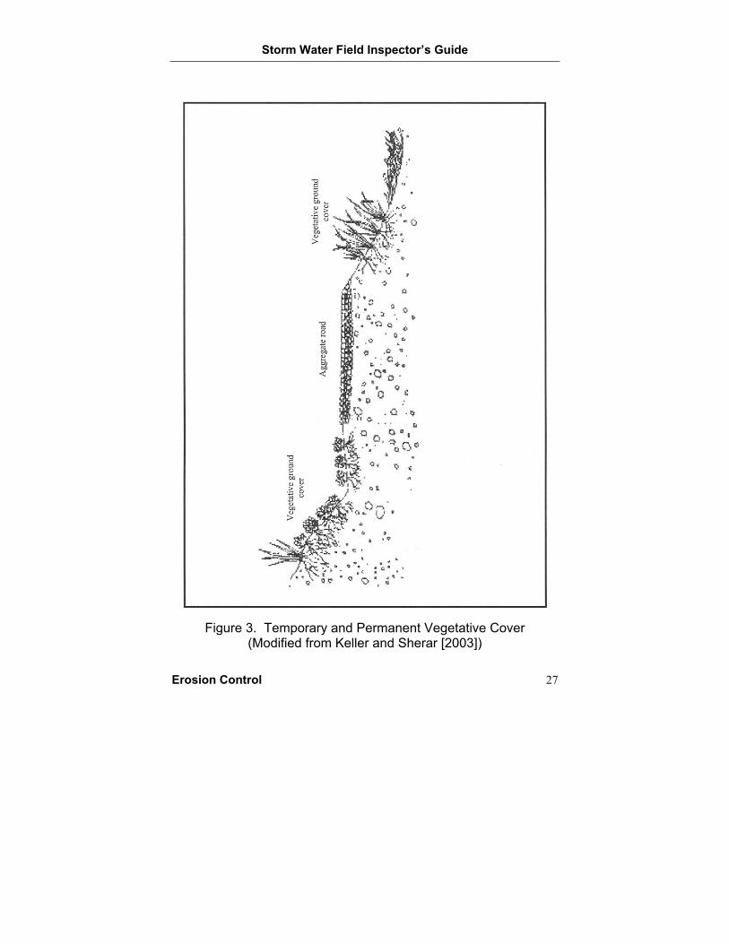
Description Vegetation is utilized to establish a temporary vegetative cover over areas disturbed by construction but not yet covered by pavement, buildings, permanent vegetation, or other structures. Temporary vegetation protects the soil from erosion until permanent structural installation or final soil stabilization is complete. Permanent vegetation provides final soil stabilization after soil-disturbing activities are complete. Figure 3 shows the proper placement of vegetative cover.
Inspection and Installation Guidelines Complete grading activities prior to applying seed mixture.
Apply compost-manufactured topsoil if required.
Apply the seed mixture uniformly to the disturbed areas as required.
Verify that applied seeds are well pulverized, loose, and uniform.
Apply fertilizer, if necessary, at the appropriate rate.
Irrigate vegetation initially and as dry conditions require.
Determine if weeds and/or pests are hindering vegetative growth.
Determine if erosion-control measures (mulching, blankets, erosion-control compost, mattings, etc.) are required to assist vegetation growth on steep slopes.
Maintenance Guidelines Seed areas that have less than 70% vegetative cover established.
Fertilize and irrigate sod vegetation as needed.
Implement a weed and pest management plan if necessary.
Implement the erosion control measures, including dikes, diversion, and slope regrading, for steep slopes where vegetation is not established due to erosion of seed.
Storm Water Field Inspector’s Guide
Erosion Control 27
Figure 3. Temporary and Permanent Vegetative Cover
(Modified from Keller and Sherar [2003])
Storm Water Field Inspector’s Guide
28 Erosion Control
MULCH
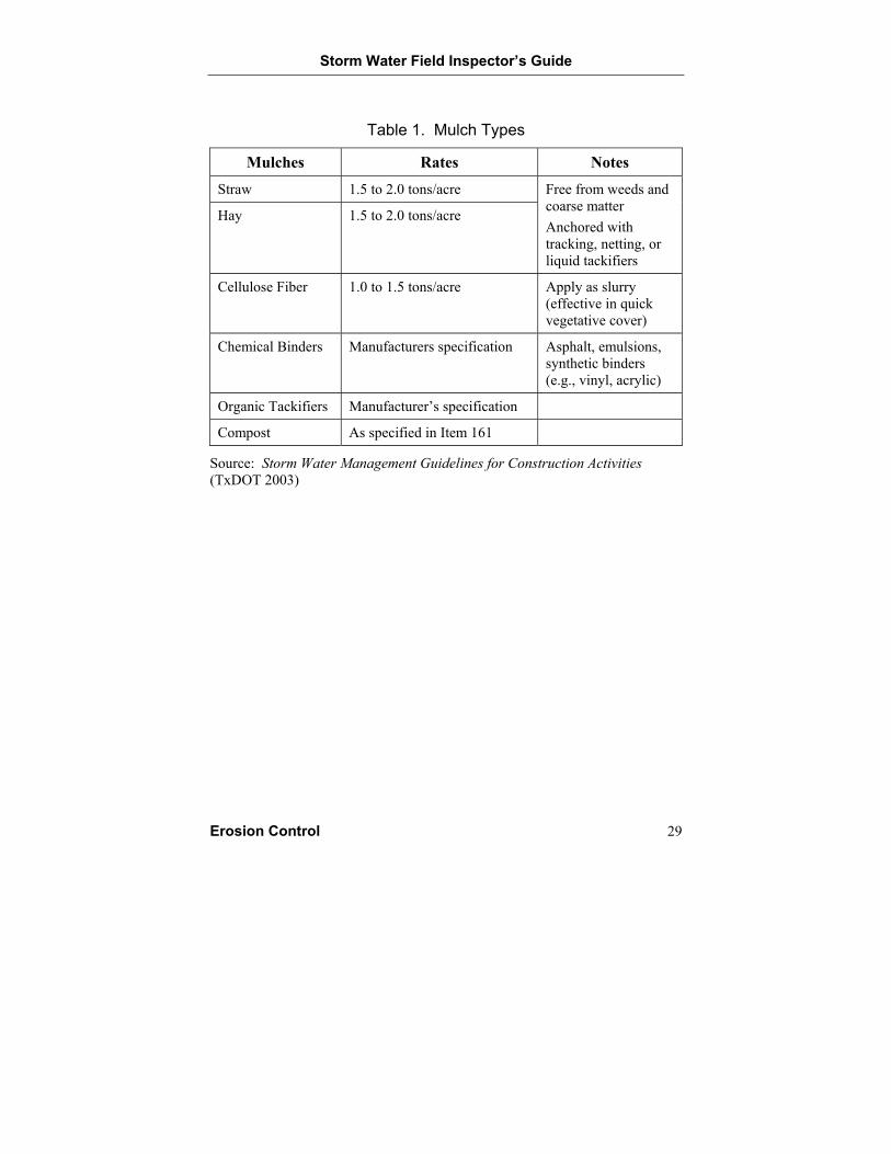
Description Mulching is the process of applying straw, hay, wood chips, compost, shredded bark, chemical binders, or other TxDOT-approved materials to the surface of disturbed soil that has been seeded. The mulch protects the seeded soil from erosive forces and conserves moisture until vegetation becomes established. Table 1 provides information on the mulch types and rates of application.
Inspection and Installation Guidelines Complete grading activities prior to seeding and mulching.
Select mulch that is free of weeds and pests; otherwise, vegetation could be hindered.
Apply the mulch immediately after seeding activities.
Apply the mulch at the appropriate rate/thickness (material, application rate, etc.).
Verify that mulch covers 80% to 100% of the disturbed soil area.
Anchor the mulch immediately after placement.
Use netting, binding chemicals, or other anchoring mechanisms when installing mulch on slopes steeper than 3:1.
Maintenance Guidelines Seed areas that exhibit inadequate vegetative growth followed by mulching.
Seal or anchor any loose areas of the mulch cover.
Replace any areas of missing mulch cover.
Storm Water Field Inspector’s Guide
Erosion Control 29
Table 1. Mulch Types
Mulches Rates Notes
Straw 1.5 to 2.0 tons/acre
Hay 1.5 to 2.0 tons/acre
Free from weeds and coarse matter Anchored with tracking, netting, or liquid tackifiers
Cellulose Fiber 1.0 to 1.5 tons/acre Apply as slurry (effective in quick vegetative cover)
Chemical Binders Manufacturers specification Asphalt, emulsions, synthetic binders (e.g., vinyl, acrylic)
Organic Tackifiers Manufacturer’s specification
Compost As specified in Item 161
Source: Storm Water Management Guidelines for Construction Activities (TxDOT 2003)
Storm Water Field Inspector’s Guide
30 Erosion Control
BLANKETS AND MATTINGS
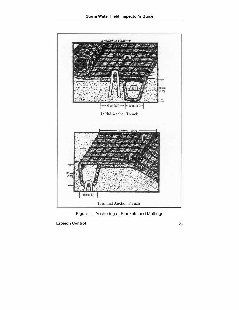
Description Blankets and mattings refer to sheets of erosion-control materials (straw, jute, wood fiber, coconut fiber, plastic netting, erosion-control compost, or other TxDOT-approved materials) placed on the surface of disturbed soil. The blankets and mattings protect the soil from erosion until vegetation becomes established. Figure 4 shows the proper anchoring of blankets and matting.
Inspection and Installation Guidelines Complete grading, fertilization, and seeding activities prior to installing a blanket or matting unless noted otherwise in the specifications.
Install the blanket or matting in accordance with the manufacturer’s recommendations and/or the specifications.
Anchor the blanket or matting to the soil surface using staples, trenches, or other TxDOT-approved anchoring methods.
Install anchor staples flush with the soil surface.
Secure blanket or matting joints (Note: Specifications typically require a minimum amount of overlap).
Identify areas where the blanket or matting is loose, damaged, or missing.
Maintenance Guidelines Seed areas that exhibit inadequate vegetative growth followed by anchoring or replacement of the blanket or matting.
Anchor any loose areas of the blanket or matting.
Replace any damaged or missing areas of the blanket or matting.
Storm Water Field Inspector’s Guide
Erosion Control 31
Figure 4. Anchoring of Blankets and Mattings
Storm Water Field Inspector’s Guide
32 Erosion Control
SODDING
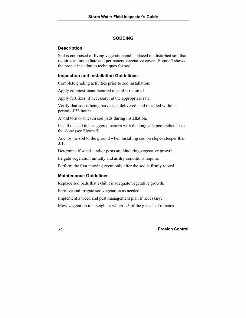
Description Sod is composed of living vegetation and is placed on disturbed soil that requires an immediate and permanent vegetative cover. Figure 5 shows the proper installation techniques for sod.
Inspection and Installation Guidelines Complete grading activities prior to sod installation.
Apply compost-manufactured topsoil if required.
Apply fertilizer, if necessary, at the appropriate rate.
Verify that sod is being harvested, delivered, and installed within a period of 36 hours.
Avoid torn or uneven sod pads during installation.
Install the sod in a staggered pattern with the long side perpendicular to the slope (see Figure 5).
Anchor the sod to the ground when installing sod on slopes steeper than 3:1.
Determine if weeds and/or pests are hindering vegetative growth.
Irrigate vegetation initially and as dry conditions require.
Perform the first mowing event only after the sod is firmly rooted.
Maintenance Guidelines Replace sod pads that exhibit inadequate vegetative growth.
Fertilize and irrigate sod vegetation as needed.
Implement a weed and pest management plan if necessary.
Mow vegetation to a height at which 1/3 of the grass leaf remains.
Storm Water Field Inspector’s Guide
Erosion Control 33
Figure 5. Sod Installation Techniques
(Adapted from Virginia Department of Conservation and Recreation [1992])
Storm Water Field Inspector’s Guide
34 Erosion Control
INTERCEPTOR AND PERIMETER SWALES
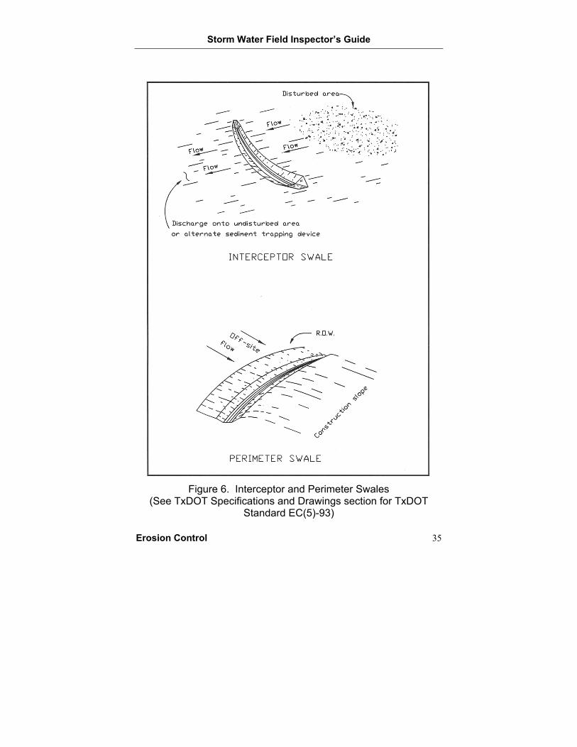
Description Interceptor and perimeter swales are channels that have been excavated across disturbed soil areas or along the perimeter of a construction site. The swales prevent off-site storm water runoff from entering the disturbed area and/or prevent the runoff from leaving the construction site or disturbed area. The runoff from the swale is directed to a sediment trap, sediment basin, or other outlet structure built for handling the sediment-laden runoff. Figure 6 shows the proper placement of interceptor and perimeter swales.
Inspection and Installation Guidelines Check that the depth of the swale is at least 1 foot or more.
Check that the side slopes of the swale are 2:1 or flatter.
Check for proper drainage along the swale by verifying that ponding is not occurring.
Check that runoff is draining to the outlet structure.
Remove trash or debris along the swale to prevent ponding or other drainage problems.
Stabilize the bottom and side slopes of the swale as well as the outlet structure with vegetation, rip-rap, blankets, matting, or other erosion control measures if runoff velocities are high enough to erode soil along the swale.
Stabilize vehicle crossing points across swales.
Maintenance Guidelines Re-grade swale to ensure proper drainage.
Remove trash and debris.
Stabilize swale, vehicle crossing points, and outlet structures as necessary to control erosion.
Storm Water Field Inspector’s Guide
Erosion Control 35
Figure 6. Interceptor and Perimeter Swales
(See TxDOT Specifications and Drawings section for TxDOT Standard EC(5)-93)
Storm Water Field Inspector’s Guide
36 Erosion Control
DIVERSION, INTERCEPTOR, AND PERIMETER DIKES
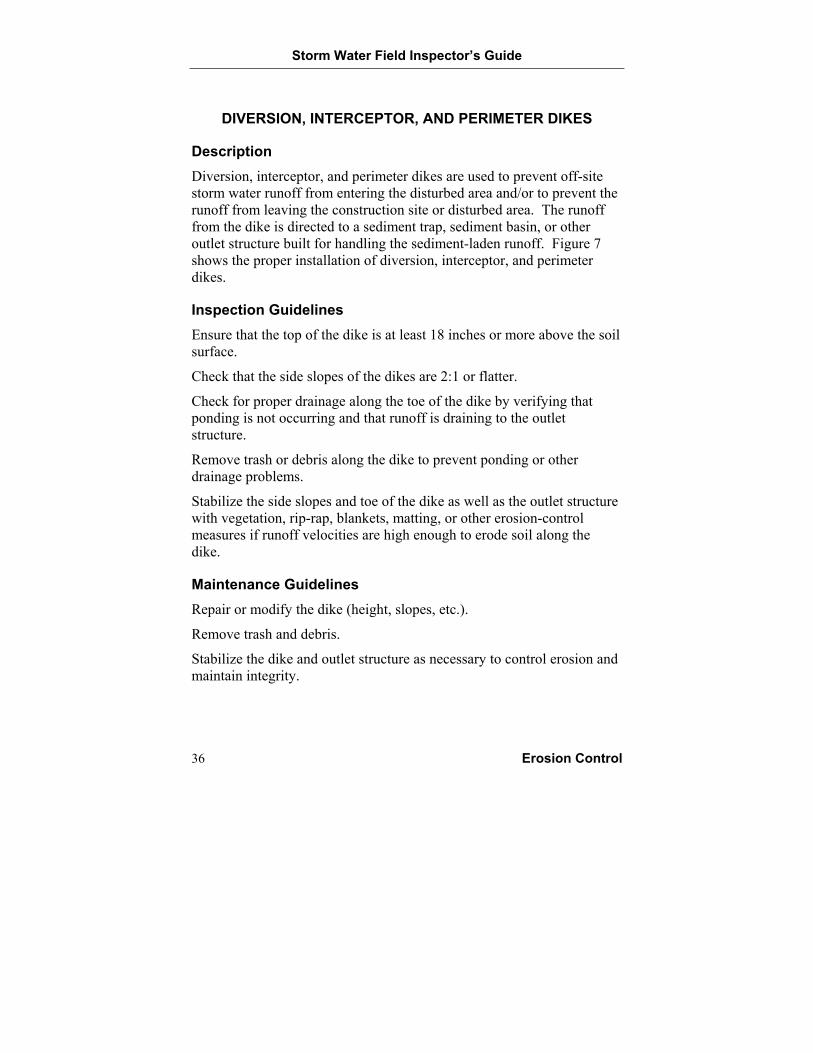
Description Diversion, interceptor, and perimeter dikes are used to prevent off-site storm water runoff from entering the disturbed area and/or to prevent the runoff from leaving the construction site or disturbed area. The runoff from the dike is directed to a sediment trap, sediment basin, or other outlet structure built for handling the sediment-laden runoff. Figure 7 shows the proper installation of diversion, interceptor, and perimeter dikes.
Inspection Guidelines Ensure that the top of the dike is at least 18 inches or more above the soil surface.
Check that the side slopes of the dikes are 2:1 or flatter.
Check for proper drainage along the toe of the dike by verifying that ponding is not occurring and that runoff is draining to the outlet structure.
Remove trash or debris along the dike to prevent ponding or other drainage problems.
Stabilize the side slopes and toe of the dike as well as the outlet structure with vegetation, rip-rap, blankets, matting, or other erosion-control measures if runoff velocities are high enough to erode soil along the dike.
Maintenance Guidelines Repair or modify the dike (height, slopes, etc.).
Remove trash and debris.
Stabilize the dike and outlet structure as necessary to control erosion and maintain integrity.
Storm Water Field Inspector’s Guide
Erosion Control 37
Figure 7. Diversion, Interceptor, and Perimeter Dikes
(See TxDOT Specifications and Drawings section for TxDOT Standard EC(4)-93)
Storm Water Field Inspector’s Guide
38 Erosion Control
STONE OUTLET STRUCTURES
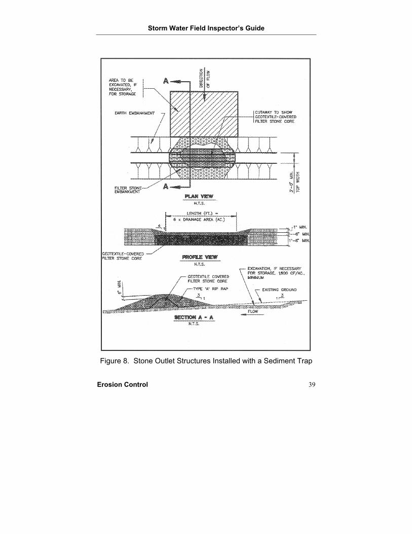
Description A stone outlet structure is a temporary, crushed-stone filter dam typically installed in conjunction with and as part of a diversion dike, interceptor dike, perimeter dike, pipe slope drain, or sediment trap or basin. A stone outlet structure assists in reducing storm water runoff velocities as well as in trapping sediments in the runoff. Figure 8 shows the proper installation of stone outlet structures with a sediment trap.
Inspection and Installation Guidelines Ensure that the top of the stone filter dam is at least 6 inches below the top of the adjacent earthen dikes.
Verify that the crushed stone used for the dam meets size requirements.
If used at the center of the rock filter dam, ensure that the geotextile fabric is completely covered by the crushed stone.
Remove trash and debris accumulating at the upstream side of the stone filter dam.
Remove accumulated sediment that has reached a height equal to 1/3 of the structure or 1 foot, whichever is less.
Place removed sediment in an area that is protected from erosion.
Maintenance Guidelines Repair or modify stone filter dam.
Remove trash and debris.
Remove accumulated sediment regularly.
Storm Water Field Inspector’s Guide
Erosion Control 39
Figure 8. Stone Outlet Structures Installed with a Sediment Trap
Storm Water Field Inspector’s Guide
40 Erosion Control
PIPE SLOPE DRAIN
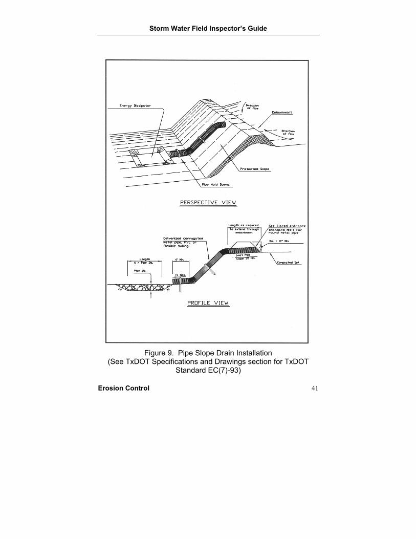
Description A pipe slope drain is an erosion-control device that combines an earthen embankment and a rigid or flexible pipe to transport water runoff over an exposed slope without causing erosion. Figure 9 shows the proper installation of a pipe slope drain.
Inspection and Installation Guidelines Secure the drainpipe to the ground surface.
Verify that the drainpipe is free of leaks.
Check that the dike height at the top of the slope is at least 1 foot higher than the top of the drainpipe to prevent water from flowing over the dike.
Remove trash and debris accumulating at the top and bottom of the slope and within the pipe.
Stabilize the area around the inlet and outlet of the drainpipe with rip-rap, blankets, rock berm, or other erosion-control measures if runoff velocities are high enough to erode soil.
Maintenance Guidelines Repair or modify the pipe slope drain.
Remove trash and debris.
Stabilize the drainpipe’s inlet and outlet as necessary to control erosion.
Storm Water Field Inspector’s Guide
Erosion Control 41
Figure 9. Pipe Slope Drain Installation
(See TxDOT Specifications and Drawings section for TxDOT Standard EC(7)-93)

Storm Water Field Inspector’s Guide
Temporary Sediment Controls 43
BEST MANAGEMENT PRACTICES— TEMPORARY SEDIMENT CONTROLS
Sandbag Berm
Silt Fence
Temporary Erosion Control Device
Triangular Filter Dike
Rock Berm
Hay Bale Dike
Stabilized Construction Exit
Brush Berm
Sediment Trap
Sediment Basin
Storm Water Field Inspector’s Guide
44 Temporary Sediment Controls
SANDBAG BERM
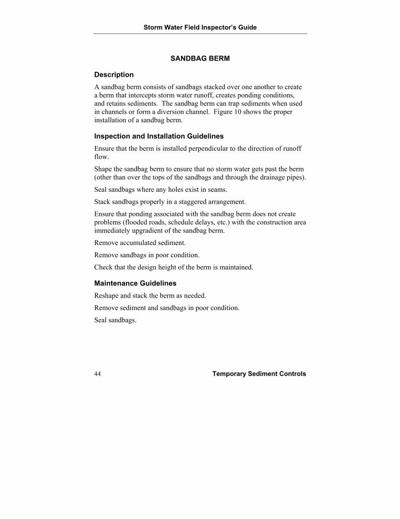
Description A sandbag berm consists of sandbags stacked over one another to create a berm that intercepts storm water runoff, creates ponding conditions, and retains sediments. The sandbag berm can trap sediments when used in channels or form a diversion channel. Figure 10 shows the proper installation of a sandbag berm.
Inspection and Installation Guidelines Ensure that the berm is installed perpendicular to the direction of runoff flow.
Shape the sandbag berm to ensure that no storm water gets past the berm (other than over the tops of the sandbags and through the drainage pipes).
Seal sandbags where any holes exist in seams.
Stack sandbags properly in a staggered arrangement.
Ensure that ponding associated with the sandbag berm does not create problems (flooded roads, schedule delays, etc.) with the construction area immediately upgradient of the sandbag berm.
Remove accumulated sediment.
Remove sandbags in poor condition.
Check that the design height of the berm is maintained.
Maintenance Guidelines Reshape and stack the berm as needed.
Remove sediment and sandbags in poor condition.
Seal sandbags.
Storm Water Field Inspector’s Guide
Temporary Sediment Controls 45
Figure 10. Sandbag Berm Installation
(NCTCOG 1993)
Storm Water Field Inspector’s Guide
46 Temporary Sediment Controls
SILT FENCE
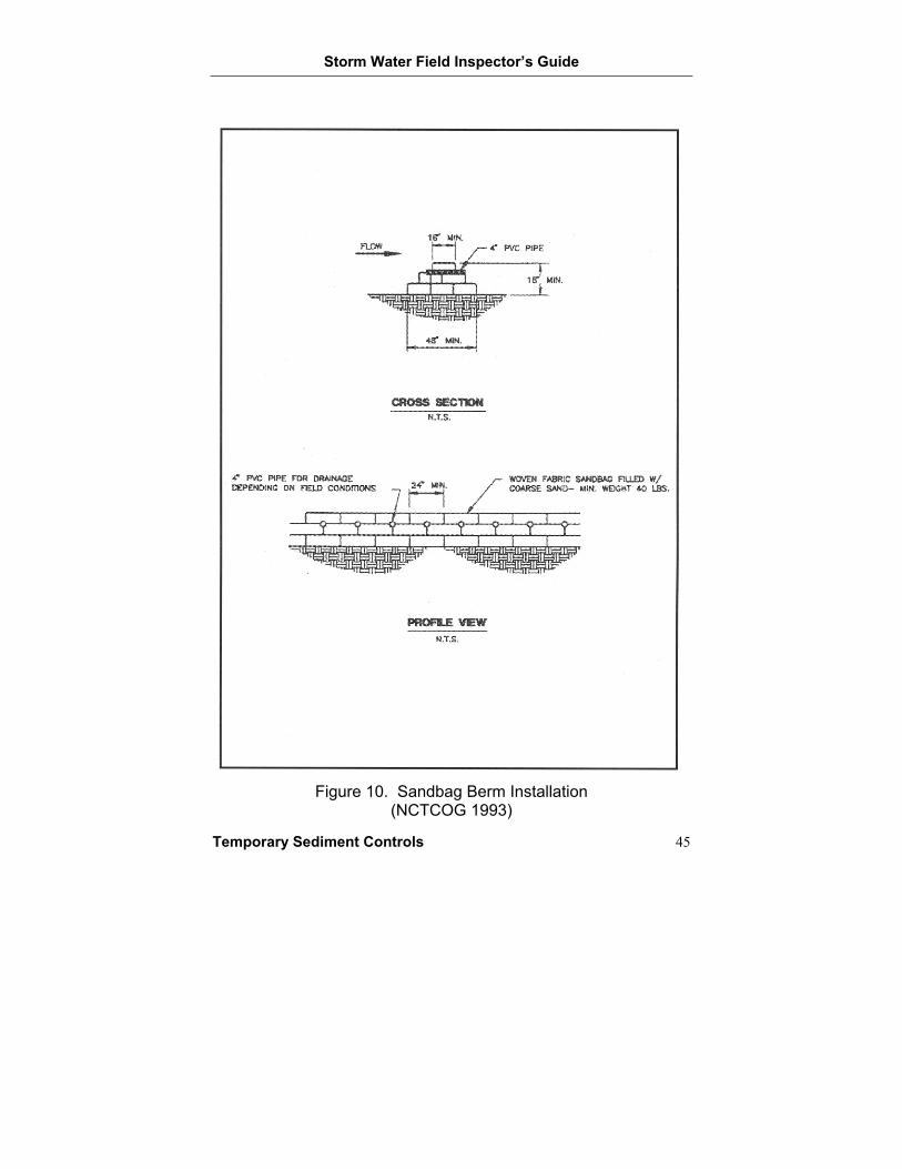
Description A silt fence consists of geotextile fabric supported by metal posts and wire mesh that prevents soil and sediment from leaving areas disturbed by construction. Figure 11 shows the proper installation of a silt fence.
Inspection and Installation Guidelines Ensure that the silt fence is installed perpendicular to the direction of runoff flow.
Securely fasten the geotextile fabric to metal posts or wire mesh.
Face the geotextile fabric towards the construction area (the steel posts and wire mesh behind the fabric should face away from the construction area).
Securely anchor the geotextile fabric to the ground so that storm water runoff does not pass beneath the fence.
Embed the steel posts a minimum of 1 foot deep and no more than 8 feet apart, or 6 feet apart where water is concentrated.
Ensure that there is a 3-foot overlap where the ends of the geotextile fabric meet.
Remove accumulated sediment when buildup reaches 1/3 the height of the fence.
Re-install the silt fence at the end of the day if it was temporarily moved (such as for vehicular access).
Repair torn or missing sections of the geotextile fabric.
Maintenance Guidelines Repair and replace the silt fence as needed.
Remove sediment.
Securely fasten and anchor the silt fence.
Storm Water Field Inspector’s Guide
Temporary Sediment Controls 47
Figure 11. Silt Fence Installation
(See TxDOT Specifications and Drawings section for TxDOT Standard EC(1)-93)
Storm Water Field Inspector’s Guide
48 Temporary Sediment Controls
TEMPORARY EROSION CONTROL DEVICE
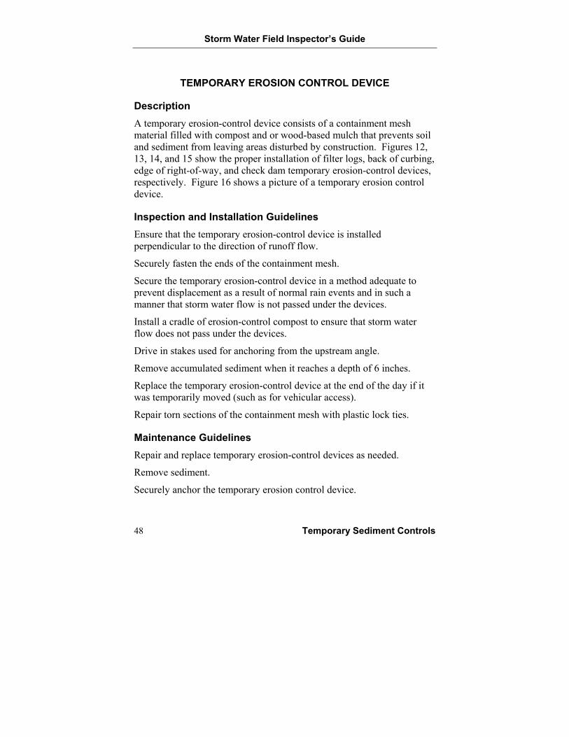
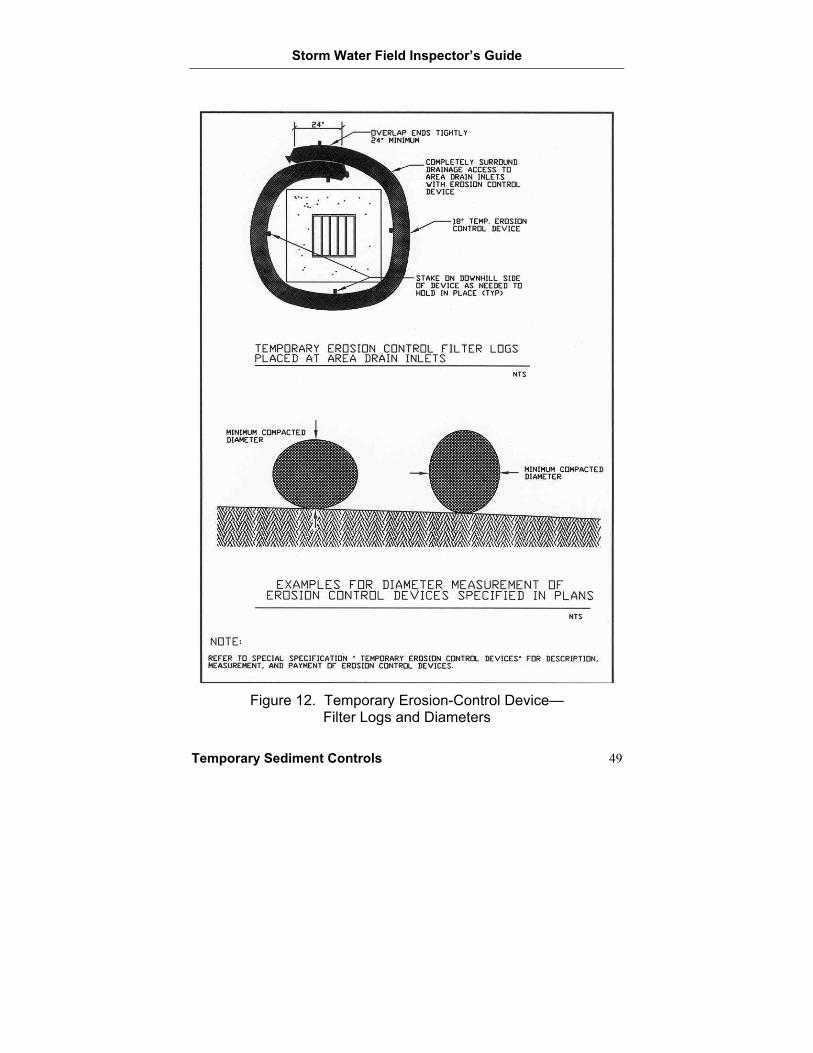
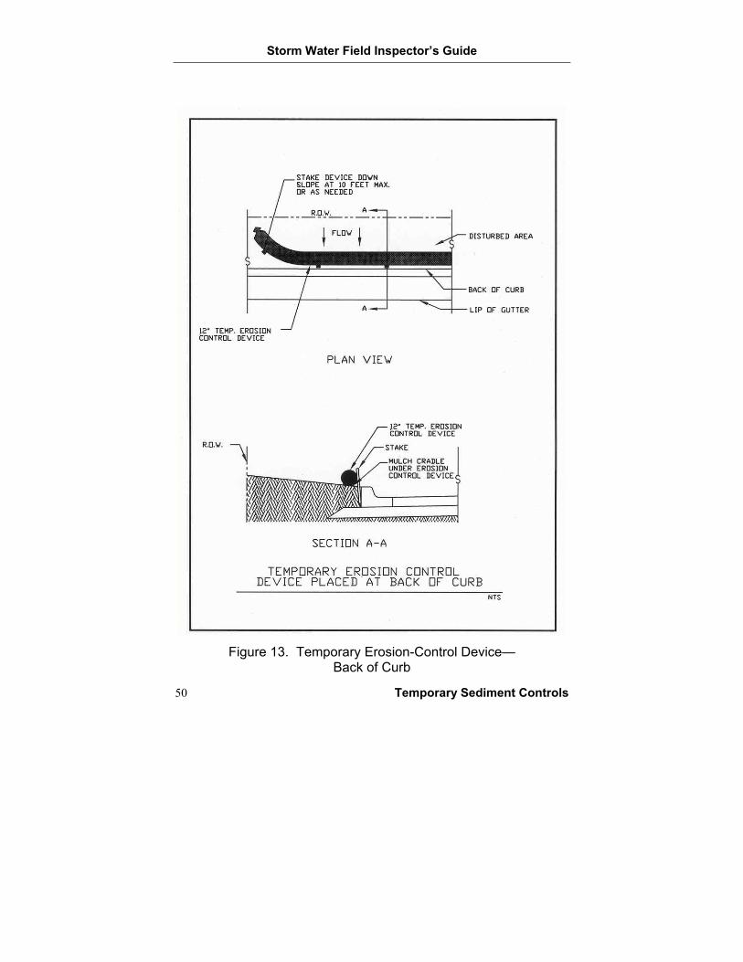
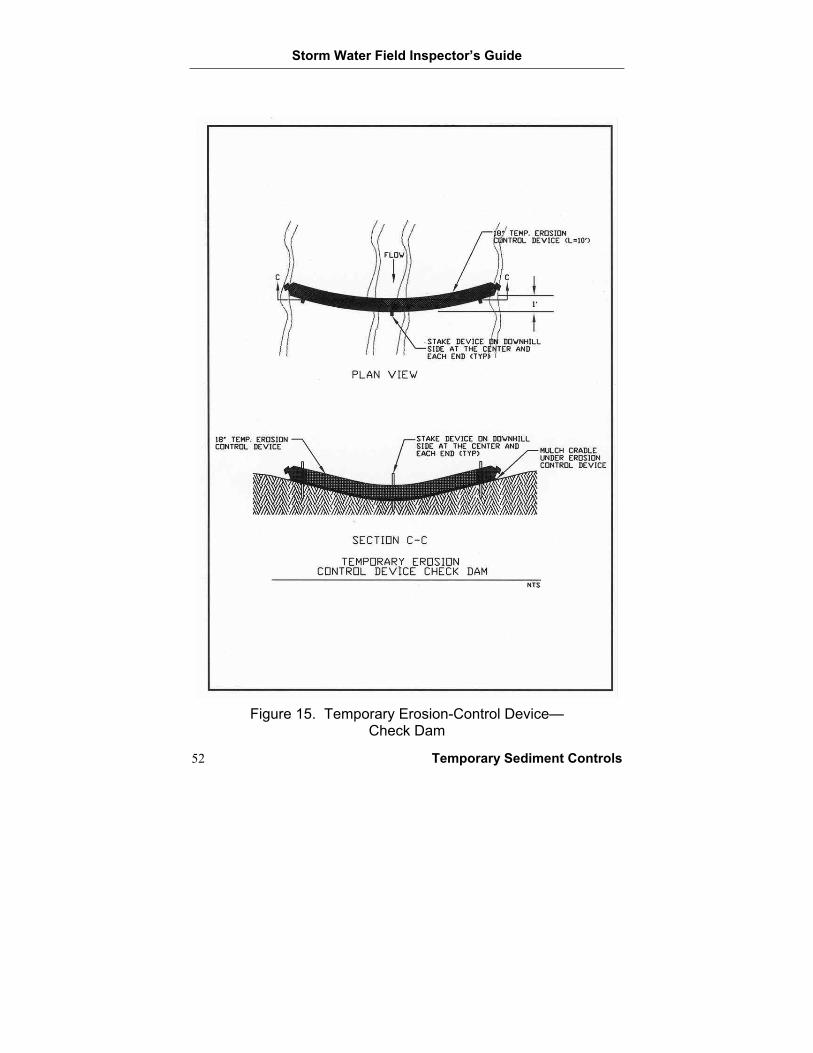
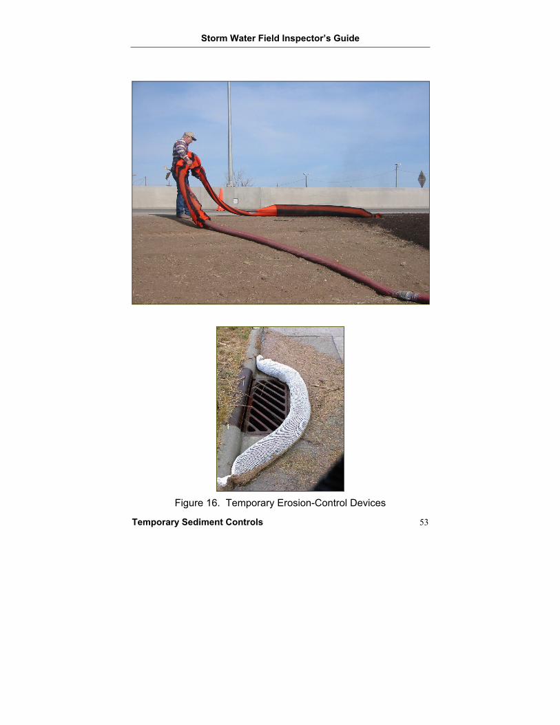
Description A temporary erosion-control device consists of a containment mesh material filled with compost and or wood-based mulch that prevents soil and sediment from leaving areas disturbed by construction. Figures 12, 13, 14, and 15 show the proper installation of filter logs, back of curbing, edge of right-of-way, and check dam temporary erosion-control devices, respectively. Figure 16 shows a picture of a temporary erosion control device.
Inspection and Installation Guidelines Ensure that the temporary erosion-control device is installed perpendicular to the direction of runoff flow.
Securely fasten the ends of the containment mesh.
Secure the temporary erosion-control device in a method adequate to prevent displacement as a result of normal rain events and in such a manner that storm water flow is not passed under the devices.
Install a cradle of erosion-control compost to ensure that storm water flow does not pass under the devices.
Drive in stakes used for anchoring from the upstream angle.
Remove accumulated sediment when it reaches a depth of 6 inches.
Replace the temporary erosion-control device at the end of the day if it was temporarily moved (such as for vehicular access).
Repair torn sections of the containment mesh with plastic lock ties.
Maintenance Guidelines Repair and replace temporary erosion-control devices as needed.
Remove sediment.
Securely anchor the temporary erosion control device.
Storm Water Field Inspector’s Guide
Temporary Sediment Controls 49
Figure 12. Temporary Erosion-Control Device—
Filter Logs and Diameters
Storm Water Field Inspector’s Guide
50 Temporary Sediment Controls
Figure 13. Temporary Erosion-Control Device—
Back of Curb
Storm Water Field Inspector’s Guide
Temporary Sediment Controls 51
Figure 14. Temporary Erosion-Control Device—
Edge of Right-of-Way
Storm Water Field Inspector’s Guide
52 Temporary Sediment Controls
Figure 15. Temporary Erosion-Control Device—
Check Dam
Storm Water Field Inspector’s Guide
Temporary Sediment Controls 53
Figure 16. Temporary Erosion-Control Devices
Storm Water Field Inspector’s Guide
54 Temporary Sediment Controls
TRIANGULAR FILTER DIKE
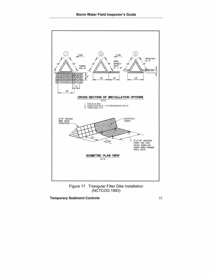
Description A triangular filter dike consists of geotextile fabric wrapped around a triangle-shaped, wire-mesh frame. A triangular filter dike intercepts storm water runoff and retains sediment. Figure 17 shows the proper installation of a triangular filter dike.
Inspection and Installation Guidelines Ensure that the dike is installed perpendicular to the direction of runoff flow.
Repair torn or missing sections of geotextile fabric along the dike.
Repair damaged sections of the wire mesh frame.
Securely anchor the dike to the ground by embedding, staples, nails, or other TxDOT-approved methods.
Securely attach adjacent dikes so that no gap exists at dike junctions.
Re-install dikes at the end of the day if they are temporarily moved (such as for vehicular access).
Remove accumulated sediment.
Maintenance Guidelines Repair and replace triangular dikes.
Securely anchor and attach dikes.
Remove sediment.
Storm Water Field Inspector’s Guide
Temporary Sediment Controls 55
Figure 17. Triangular Filter Dike Installation
(NCTCOG 1993)
Storm Water Field Inspector’s Guide
56 Temporary Sediment Controls
ROCK BERM
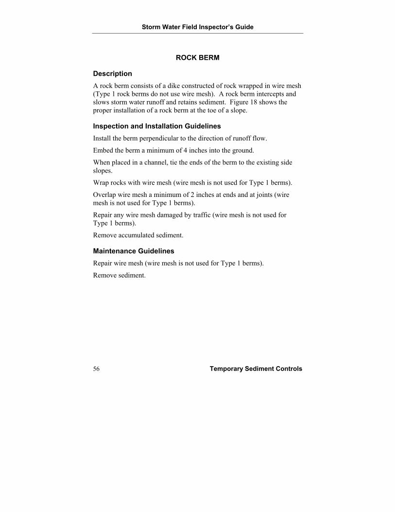
Description A rock berm consists of a dike constructed of rock wrapped in wire mesh (Type 1 rock berms do not use wire mesh). A rock berm intercepts and slows storm water runoff and retains sediment. Figure 18 shows the proper installation of a rock berm at the toe of a slope.
Inspection and Installation Guidelines Install the berm perpendicular to the direction of runoff flow.
Embed the berm a minimum of 4 inches into the ground.
When placed in a channel, tie the ends of the berm to the existing side slopes.
Wrap rocks with wire mesh (wire mesh is not used for Type 1 berms).
Overlap wire mesh a minimum of 2 inches at ends and at joints (wire mesh is not used for Type 1 berms).
Repair any wire mesh damaged by traffic (wire mesh is not used for Type 1 berms).
Remove accumulated sediment.
Maintenance Guidelines Repair wire mesh (wire mesh is not used for Type 1 berms).
Remove sediment.
Storm Water Field Inspector’s Guide
Temporary Sediment Controls 57
Figure 18. Rock Berm Installation at the Toe of a Slope
(See TxDOT Specifications and Drawings section for TxDOT Standard EC(2)-93)
Storm Water Field Inspector’s Guide
58 Temporary Sediment Controls
HAY BALE DIKE
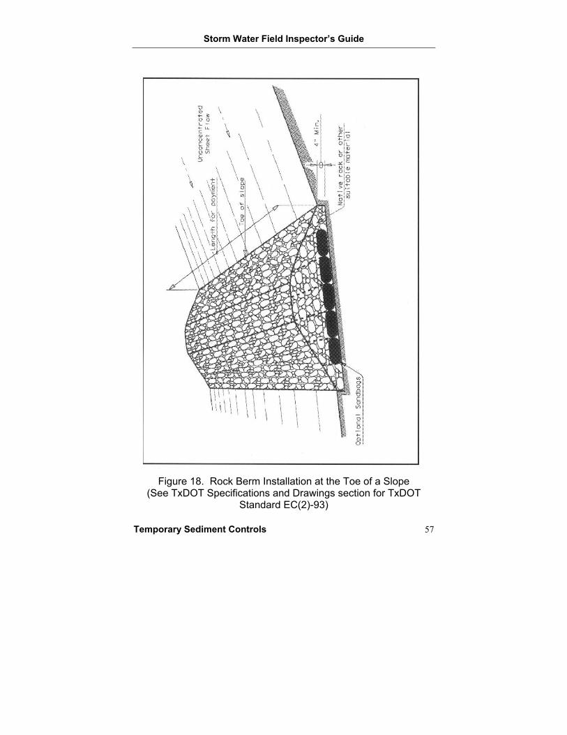
Description A hay bale dike is a temporary berm constructed of hay or straw bales. The dike intercepts storm water runoff and retains sediments. Hay bale dikes require frequent maintenance and are only used when no other erosion control measure is an option. Figure 19 shows the proper installation of a hay bale dike.
Inspection and Installation Guidelines Install the dike perpendicular to the direction of runoff flow.
Embed bales a minimum of 4 inches into the ground.
Anchor bales to the ground using wooden stakes or metal rebar driven a minimum of 6 inches into the ground.
Angle the first stake in each bale toward the previously laid bale to force the bales together.
Remove accumulated sediment.
Replace bales every 2 months or sooner.
Maintenance Guidelines Repair and replace hay bales.
Remove sediment.
Anchor and embed the bales properly.
Storm Water Field Inspector’s Guide
Temporary Sediment Controls 59
Figure 19. Hay Bale Dike Installation
(See TxDOT Specifications and Drawings section for TxDOT Standard EC(1)-93)
Storm Water Field Inspector’s Guide
60 Temporary Sediment Controls
STABILIZED CONSTRUCTION EXIT
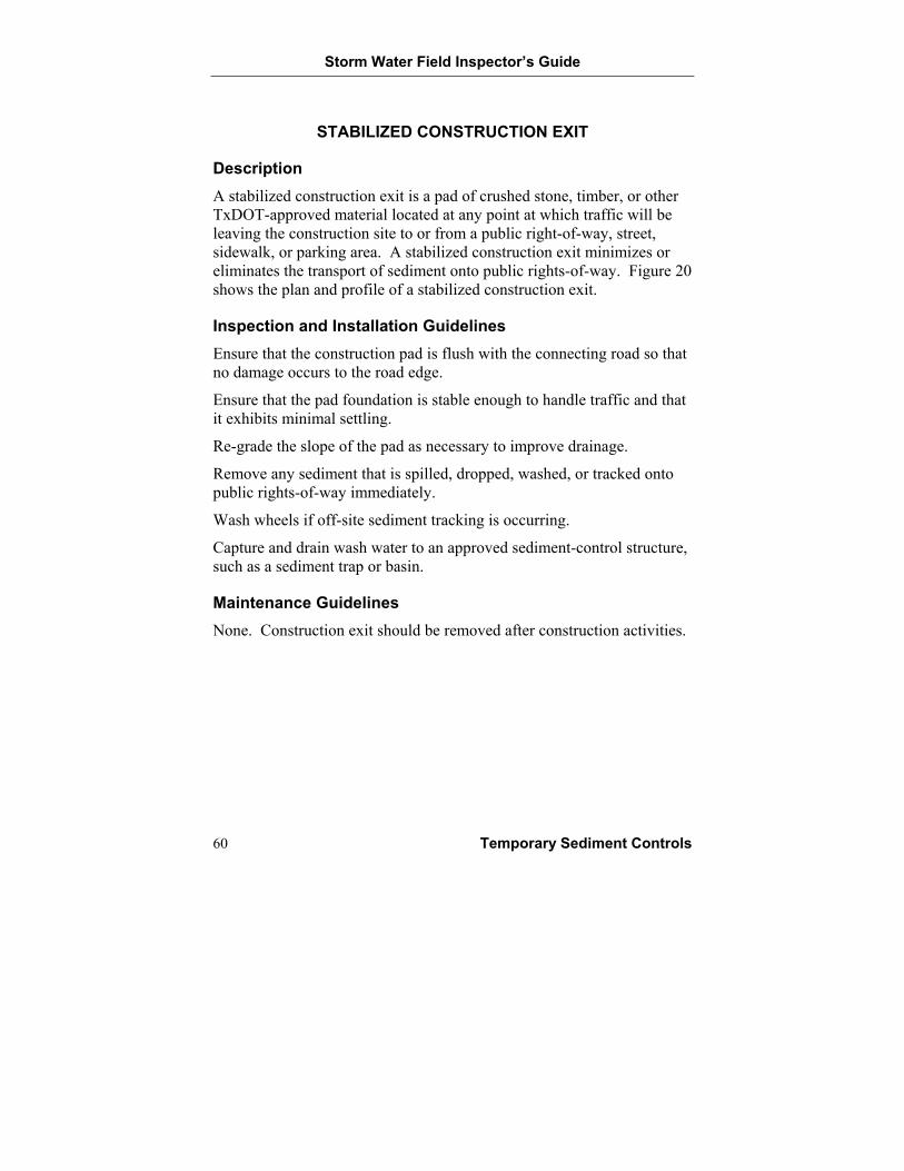
Description A stabilized construction exit is a pad of crushed stone, timber, or other TxDOT-approved material located at any point at which traffic will be leaving the construction site to or from a public right-of-way, street, sidewalk, or parking area. A stabilized construction exit minimizes or eliminates the transport of sediment onto public rights-of-way. Figure 20 shows the plan and profile of a stabilized construction exit.
Inspection and Installation Guidelines Ensure that the construction pad is flush with the connecting road so that no damage occurs to the road edge.
Ensure that the pad foundation is stable enough to handle traffic and that it exhibits minimal settling.
Re-grade the slope of the pad as necessary to improve drainage.
Remove any sediment that is spilled, dropped, washed, or tracked onto public rights-of-way immediately.
Wash wheels if off-site sediment tracking is occurring.
Capture and drain wash water to an approved sediment-control structure, such as a sediment trap or basin.
Maintenance Guidelines None. Construction exit should be removed after construction activities.
Storm Water Field Inspector’s Guide
Temporary Sediment Controls 61
Figure 20. Stabilized Construction Exit—Plan and Profile
Storm Water Field Inspector’s Guide
62 Temporary Sediment Controls
BRUSH BERM
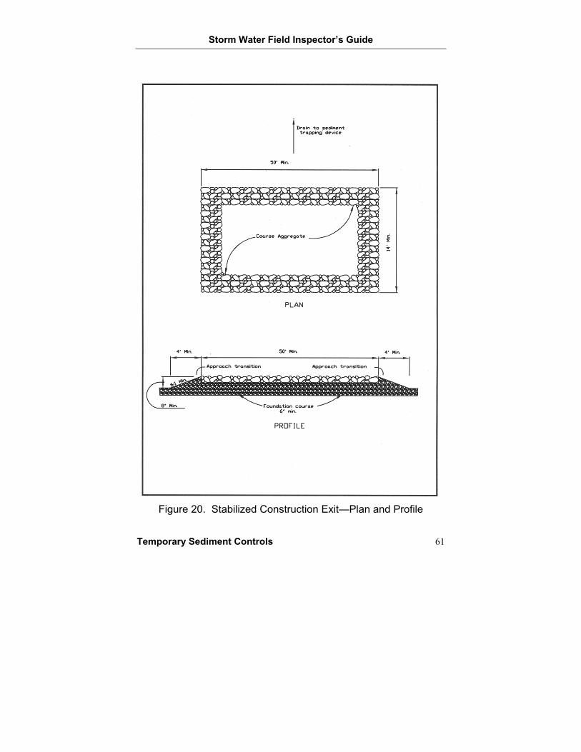
Description A brush berm is a temporary berm constructed of hand-placed brush from woody plants and installed at the toe of a slope or the perimeter of a construction site. Anchor ropes are used to secure the brush to the ground. A brush berm intercepts and slows the surface water runoff and retains sediment. Figure 21 shows the proper installation of a brush berm.
Inspection and Installation Guidelines Securely anchor the brush to the ground with stakes.
Ensure that filter fabric is fully anchored in the uphill trench.
Replace any brush berm that exhibits signs of deterioration or instability.
Inspect filter fabric anchor for tears and replace damaged sections properly.
Remove trash or debris accumulating along the brush berm.
Remove accumulated sediment that has reached a height equal to 1/3 of the berm height or 1 foot, whichever is less.
Maintenance Guidelines Remove trash, debris, and sediment.
Secure anchor ropes.
Storm Water Field Inspector’s Guide
Temporary Sediment Controls 63
Figure 21. Brush Berm Installation
(VDCR 1992)
Storm Water Field Inspector’s Guide
64 Temporary Sediment Controls
SEDIMENT TRAP
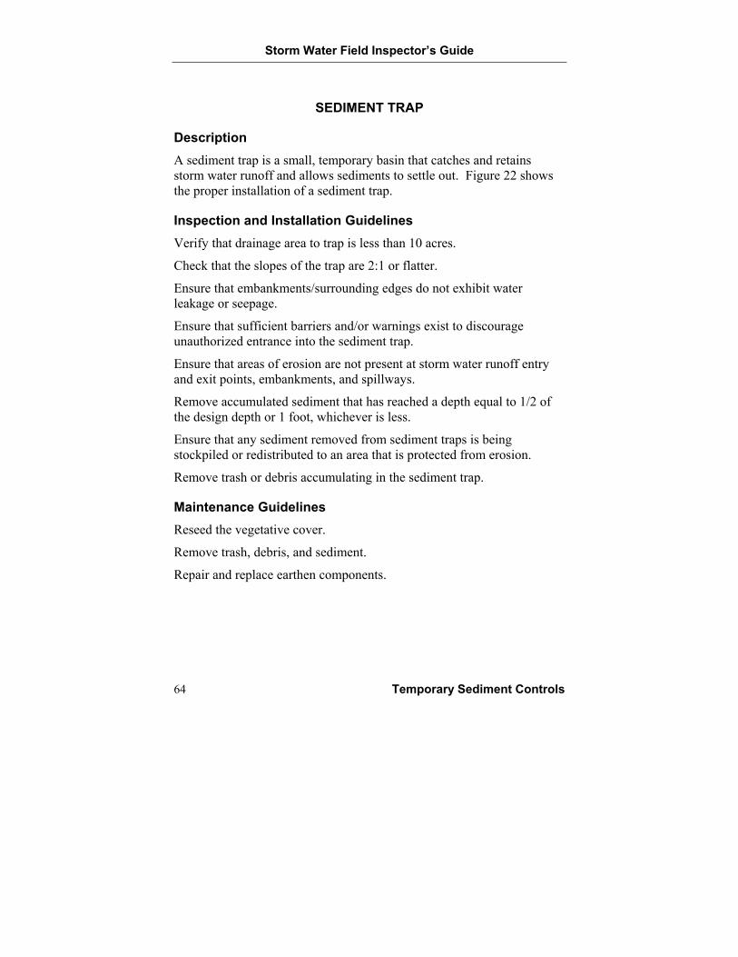
Description A sediment trap is a small, temporary basin that catches and retains storm water runoff and allows sediments to settle out. Figure 22 shows the proper installation of a sediment trap.
Inspection and Installation Guidelines Verify that drainage area to trap is less than 10 acres.
Check that the slopes of the trap are 2:1 or flatter.
Ensure that embankments/surrounding edges do not exhibit water leakage or seepage.
Ensure that sufficient barriers and/or warnings exist to discourage unauthorized entrance into the sediment trap.
Ensure that areas of erosion are not present at storm water runoff entry and exit points, embankments, and spillways.
Remove accumulated sediment that has reached a depth equal to 1/2 of the design depth or 1 foot, whichever is less.
Ensure that any sediment removed from sediment traps is being stockpiled or redistributed to an area that is protected from erosion.
Remove trash or debris accumulating in the sediment trap.
Maintenance Guidelines Reseed the vegetative cover.
Remove trash, debris, and sediment.
Repair and replace earthen components.
Storm Water Field Inspector’s Guide
Temporary Sediment Controls 65
Figure 22. Sediment Trap Installation
(See TxDOT Specifications and Drawings section for TxDOT Standard EC(6)-93)
Storm Water Field Inspector’s Guide
66 Temporary Sediment Controls
SEDIMENT BASIN
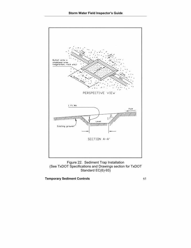
Description A sediment basin is a settling pond that intercepts and retains storm water runoff and allows suspended sediments to settle out. A sediment basin is a larger version of a sediment trap. Figure 23 shows the proper installation of a sediment basin.
Inspection and Installation Guidelines Verify that drainage area to basin is less than 100 acres.
Ensure that the minimum top width of the embankment is 3 feet.
Check that the side slopes are 3:1 or flatter.
Ensure that areas of erosion are not present at storm water runoff entry and exit points, embankments, spillways, and outlet pipe.
Remove accumulated sediment when the volume equals 1/2 of the design volume.
Ensure that any sediment removed from sediment basins is being stockpiled or redistributed to an area that is protected from erosion.
Remove trash or debris accumulating in the sediment basin.
Ensure that embankments/surrounding edges do not exhibit water leakage or seepage.
Repair pipes that exhibit any signs of deterioration.
Ensure that sufficient barriers and/or warnings exist to discourage unauthorized entrance into the sediment basin.
Maintenance Guidelines Remove trash, debris, and sediment.
Repair and replace earthen and structural components.
Storm Water Field Inspector’s Guide
Temporary Sediment Controls 67
Figure 23. Sediment Basin Installation
(See TxDOT Specifications and Drawings section for TxDOT Standard EC(6)-93)

Storm Water Field Inspector’s Guide
Permanent Sediment Controls 69
BEST MANAGEMENT PRACTICES— PERMANENT SEDIMENT CONTROL
Grassy Swales
Retention/Irrigation Systems
Vegetative Filter Strips
Extended Detention Basin
Constructed Wetland
Wet Basin
Sand Filter
Storm Water Field Inspector’s Guide
70 Permanent Sediment Controls
GRASSY SWALES
Description Grassy swales are vegetated channels that transport storm water runoff as well as remove sediments and pollutants by filtration through grass and infiltration through soil.
Inspection and Installation Guidelines Ensure that the swale is graded properly so that storm water runoff drains along the swale and does not pond at specific locations.
Ensure that sufficient freeboard (the height needed to contain storm water runoff) exists along the swale.
Apply fertilizer, if necessary, at the appropriate rate.
Remove trash or debris accumulating in the swale.
Determine if areas of erosion or inadequate vegetative growth are present along the swale.
Irrigate vegetation initially and as dry conditions require.
Determine if sediment is accumulating at inlet or outlet structures as well as along the channel.
Determine if weeds and/or pests are hindering vegetative growth.
Mow vegetation to a height of 4 to 6 inches.
Maintenance Guidelines Remove trash, debris, and sediment.
Reseed, mow, and irrigate vegetation.
Remove weeds and pests from vegetation.
Re-grade the swale.
Storm Water Field Inspector’s Guide
Permanent Sediment Controls 71
RETENTION/IRRIGATION SYSTEMS
Description A retention/irrigation system captures and stores storm water runoff in a basin. Captured water is used to irrigate appropriate landscape areas.
Inspection and Installation Guidelines Implement a nuisance (odors, weeds, insects, etc.) management system if necessary.
Remove trash or debris accumulating in the basin.
Determine if vegetation above the water line requires mowing.
Determine if any areas of erosion or inadequate vegetative growth are present on the side slopes and embankment.
Check to see that pipes, spray heads, pumps, and other structural and mechanical components of the retention/irrigation system are functioning properly.
Ensure that sediment removed from sediment basins is being stockpiled or redistributed to an area that is protected from erosion.
Irrigate vegetation initially and as dry conditions require above the water line.
Maintenance Guidelines Reseed, mow, and irrigate vegetation.
Remove trash, debris, and sediment.
Control nuisance conditions.
Repair structural and mechanical components.
Storm Water Field Inspector’s Guide
72 Permanent Sediment Controls
VEGETATIVE FILTER STRIPS
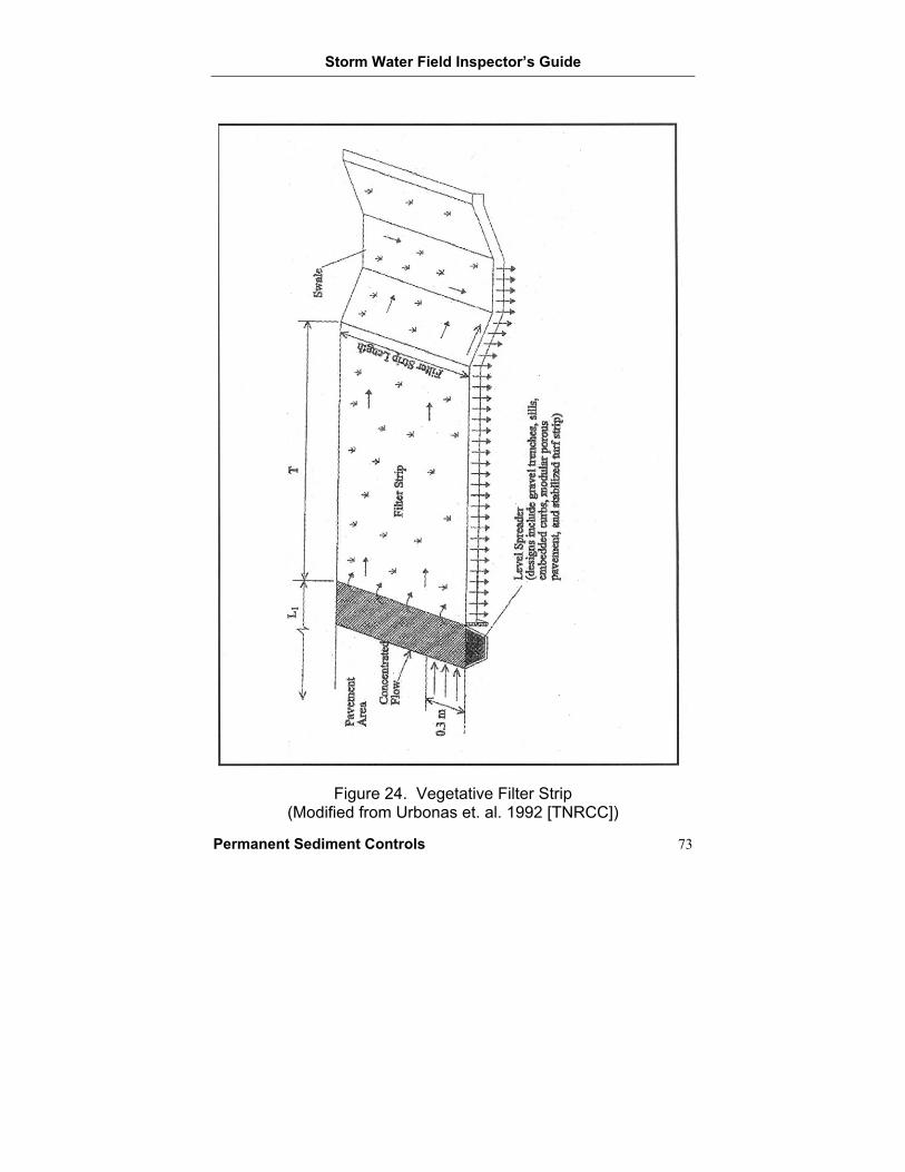
Description Vegetative filter strips are strips of dense vegetation that remove sediments and pollutants in storm water runoff through settling and filtration processes. Figure 24 shows the proper placement of a vegetative filter strip.
Inspection and Installation Guidelines Ensure that area is free of gullies that can concentrate flow.
Remove trash or debris accumulating along the vegetative filter strip.
Determine if areas of erosion or inadequate vegetative growth are present along the vegetative filter strip.
Determine if weeds and/or pests are hindering vegetative growth.
Irrigate vegetation initially and as dry conditions require.
Remove sediment accumulating along the upgradient side of the vegetative filter strip.
Implement a pest management system if necessary.
Maintenance Guidelines Remove trash, debris, and sediment.
Reseed, mow, and irrigate vegetation.
Implement pest management.
Remove accumulated sediment by hand, with a flat-bottomed shovel, or by similar means.
Storm Water Field Inspector’s Guide
Permanent Sediment Controls 73
Figure 24. Vegetative Filter Strip
(Modified from Urbonas et. al. 1992 [TNRCC])
Storm Water Field Inspector’s Guide
74 Permanent Sediment Controls
EXTENDED DETENTION BASIN
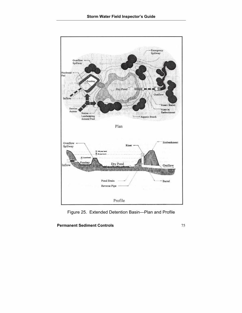
Description An extended detention basin is a normally dry pond that temporarily stores storm water runoff following a storm and removes sediments and pollutants by settlement. Figure 25 shows the plan and profile of an extended detention basin.
Inspection and Installation Guidelines Ensure that drainage area is greater than 10 acres and less than 30 acres.
Check that inlet structure reduces runoff velocity and erosion.
Remove trash or debris accumulating in the basin.
Determine if vegetation above the water line requires mowing.
Determine if any areas of erosion or inadequate vegetative growth are present on the side slopes, embankment, or emergency spillway.
Implement nuisance (odors, weeds, insects, etc.) control if necessary.
Remove accumulated sediment when buildup fills 50% of the volume allocated for sediment or when structure functioning is impaired.
Ensure that any sediment removed from sediment basins is being stockpiled or redistributed to an area that is protected from erosion.
Ensure that embankments/surrounding edges do not exhibit water leakage or seepage.
Examine structural features for deterioration, leakage, and/or cracking.
Irrigate vegetation initially and as dry conditions require.
Maintenance Guidelines Reseed, mow, and irrigate vegetation.
Remove trash, debris, and sediment.
Control nuisance conditions.
Repair and replace earthen and structural components.
Storm Water Field Inspector’s Guide
Permanent Sediment Controls 75
Figure 25. Extended Detention Basin—Plan and Profile
Storm Water Field Inspector’s Guide
76 Permanent Sediment Controls
CONSTRUCTED WETLAND
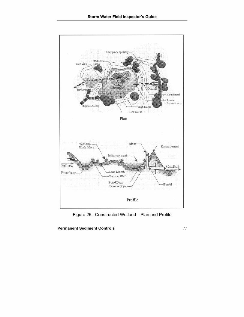
Description A constructed wetland is a permanent pond that removes sediments and pollutants from storm water runoff through physical, chemical, and biological processes. Physical processes include decreasing flow velocities; chemical processes include precipitation and chemical adsorption; and biological processes include decomposition, plant uptake, and biodegradation. Figure 26 shows the plan and profile of a constructed wetland.
Inspection and Installation Guidelines Ensure that the depth of the permanent pool is 3 to 6 feet.
Remove trash or debris accumulating in the wetland.
Determine if storm water runoff is providing a sufficient supply of water to maintain a permanent pond.
Mow or irrigate vegetation above the water line as necessary.
Determine if any areas of erosion or inadequate vegetative growth are present on the side slopes, embankment, or emergency spillway.
Ensure that any sediment removed from sediment basins is being stockpiled or redistributed to an area that is protected from erosion.
Implement nuisance (odors, weeds, insects, etc.) control if required.
Ensure that structural features and embankments/surrounding edges do not exhibit signs of deterioration, leakage, and/or cracking.
Maintenance Guidelines Obtain a supplemental water source if necessary.
Reseed, mow, and irrigate vegetation.
Remove trash and debris. Remove sediment every year.
Control nuisance conditions.
Repair and replace earthen and structural components.
Storm Water Field Inspector’s Guide
Permanent Sediment Controls 77
Figure 26. Constructed Wetland—Plan and Profile
Storm Water Field Inspector’s Guide
78 Permanent Sediment Controls
WET BASIN
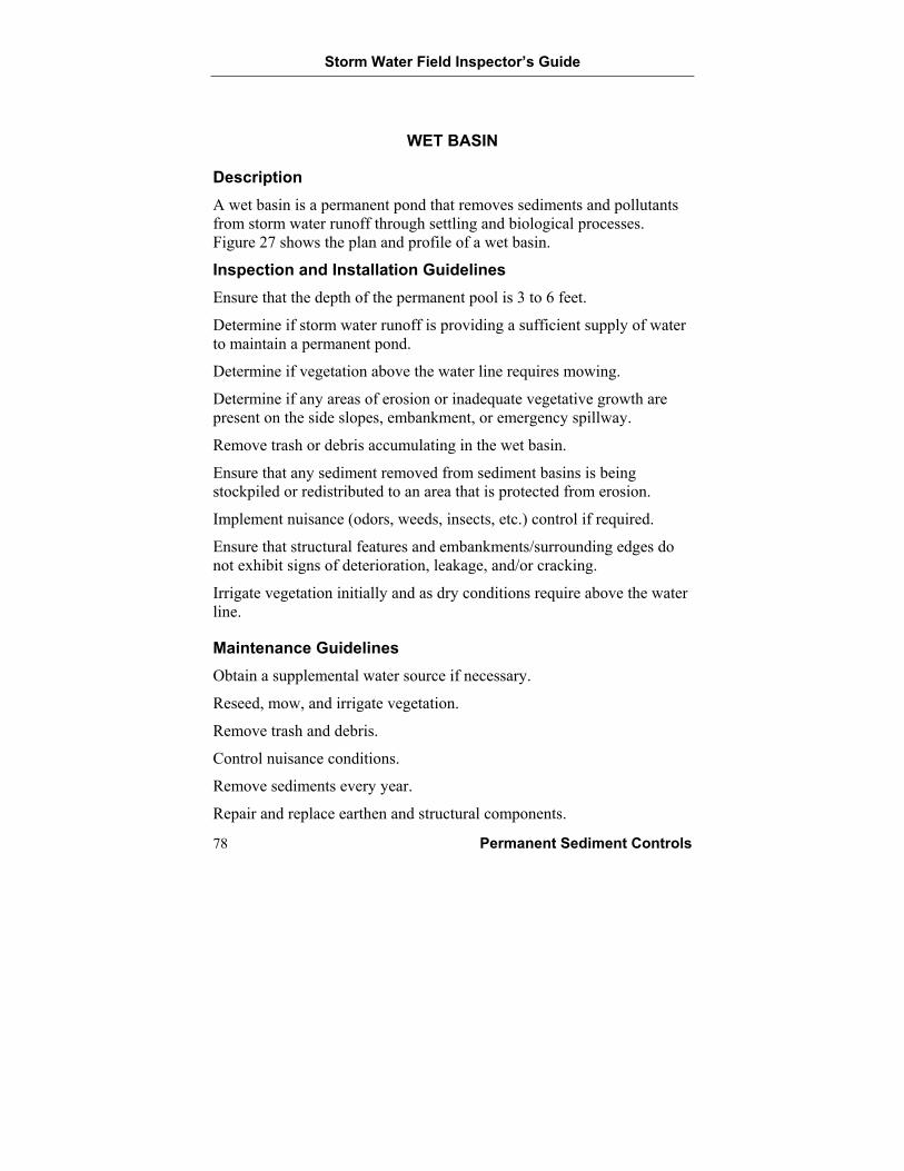
Description A wet basin is a permanent pond that removes sediments and pollutants from storm water runoff through settling and biological processes. Figure 27 shows the plan and profile of a wet basin.
Inspection and Installation Guidelines Ensure that the depth of the permanent pool is 3 to 6 feet.
Determine if storm water runoff is providing a sufficient supply of water to maintain a permanent pond.
Determine if vegetation above the water line requires mowing.
Determine if any areas of erosion or inadequate vegetative growth are present on the side slopes, embankment, or emergency spillway.
Remove trash or debris accumulating in the wet basin.
Ensure that any sediment removed from sediment basins is being stockpiled or redistributed to an area that is protected from erosion.
Implement nuisance (odors, weeds, insects, etc.) control if required.
Ensure that structural features and embankments/surrounding edges do not exhibit signs of deterioration, leakage, and/or cracking.
Irrigate vegetation initially and as dry conditions require above the water line.
Maintenance Guidelines Obtain a supplemental water source if necessary.
Reseed, mow, and irrigate vegetation.
Remove trash and debris.
Control nuisance conditions.
Remove sediments every year.
Repair and replace earthen and structural components.
Storm Water Field Inspector’s Guide
Permanent Sediment Controls 79
Figure 27. Wet Basin—Plan and Profile
Storm Water Field Inspector’s Guide
80 Permanent Sediment Controls
SAND FILTER
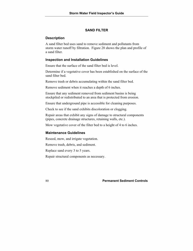
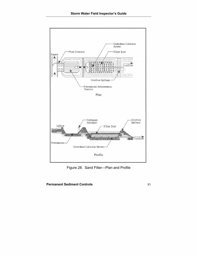
Description A sand filter bed uses sand to remove sediment and pollutants from storm water runoff by filtration. Figure 28 shows the plan and profile of a sand filter.
Inspection and Installation Guidelines Ensure that the surface of the sand filter bed is level.
Determine if a vegetative cover has been established on the surface of the sand filter bed.
Remove trash or debris accumulating within the sand filter bed.
Remove sediment when it reaches a depth of 6 inches.
Ensure that any sediment removed from sediment basins is being stockpiled or redistributed to an area that is protected from erosion.
Ensure that underground pipe is accessible for cleaning purposes.
Check to see if the sand exhibits discoloration or clogging.
Repair areas that exhibit any signs of damage to structural components (pipes, concrete drainage structures, retaining walls, etc.).
Mow vegetative cover of the filter bed to a height of 4 to 6 inches.
Maintenance Guidelines Reseed, mow, and irrigate vegetation.
Remove trash, debris, and sediment.
Replace sand every 3 to 5 years.
Repair structural components as necessary.
Storm Water Field Inspector’s Guide
Permanent Sediment Controls 81
Figure 28. Sand Filter—Plan and Profile


Storm Water Field Inspector’s Guide
Other BMPs 83
OTHER BEST MANAGEMENT PRACTICES
Good Housekeeping
Construction Wastes
Hazardous Materials
Off-Site Vehicle Tracking
Sanitary Facilities
Spills
Storm Water Field Inspector’s Guide
84 Other BMPs
GOOD HOUSEKEEPING
Good housekeeping refers to keeping a clean, orderly construction site. Good housekeeping practices are necessary to prevent storm water contamination. Examples of good housekeeping practices include the following:
• Storing chemicals, pesticides, fertilizers, fuels, etc., in a manner that prevents contact with storm water.
• Scheduling regular collection of garbage, rubbish, construction waste, and sanitary waste.
• Cleaning up spills of liquid or dry materials promptly.
• Cleaning up sediments that have been tracked by vehicles onto the site or nearby roadways.
• Controlling the dumping of excess concrete and concrete wastewater on the site.
• Ensuring that stockpiles of material such as fill are located to prevent storm water from transporting off-site.
Storm Water Field Inspector’s Guide
Other BMPs 85
CONSTRUCTION WASTES
Construction projects tend to generate a variety of excess or unused material. These wastes are sometimes called “construction wastes.” Construction wastes may include, but are not limited to, the following:
• Trees and shrubs removed during clearing and grubbing.
• Packaging materials (wood, paper, plastic, etc.).
• Scrap or surplus building materials (scrap metals, rubber, plastic and glass pieces, masonry products, plywood lumber, etc.).
• Materials resulting from the demolition of structures.
The following steps will help ensure proper disposal of construction waste as well as prevent storm water contamination:
• Select a designated waste collection area on-site.
• Provide an adequate number of containers with lids or covers that can be placed over the container prior to rainfall.
• When possible, place containers in a covered area.
• Arrange for waste collection before containers become full.
• Conduct daily site cleanups so that wastes are property managed prior to leaving the site.
• Clean up any spills immediately.
• Plan for additional containers and more frequent pickups during the demolition phase of construction.
• Verify that construction waste is collected, removed, and disposed of only at authorized disposal areas.
• Check with the local solid waste management agency for specific guidance.
Storm Water Field Inspector’s Guide
86 Other BMPs
HAZARDOUS MATERIALS
Many of the materials found at construction sites may be hazardous to the environment or to human health. At a minimum, any products in the categories listed below are considered to be hazardous:
• Paints.
• Acids for cleaning masonry surfaces.
• Cleaning chemicals.
• Asphalt products.
• Chemicals used for soil stabilization.
• Concrete-curing chemicals.
• Fuel products.
The following practices will help ensure proper disposal of hazardous wastes as well as prevent storm water contamination:
• Store materials in a manner that prevents contact with runoff.
• Check with local management authorities to determine the requirements for disposal of hazardous materials.
• Use the entire product before throwing away the container.
• Do not remove the original product label from the container.
• If surplus products are thrown away, avoid mixing products together.
• Follow the manufacturer’s recommended method of disposal.
Storm Water Field Inspector’s Guide
Other BMPs 87
• Contaminated soil is soil that has been in contact with or contains hazardous substances. Contaminated soil may be encountered on-site during earthwork activities or during the cleanup of a spill or leak of a hazardous substance. Material storage areas may also have been contaminated by undetected spills. A state or local solid waste regulatory agency should be contacted for information and procedures necessary to handle contaminated soil. Some landfills may accept contaminated soil; however, laboratory testing may be required prior to a final decision.
• Concrete trucks should not be washed out at the construction site unless sufficient area has been made available to fully capture the wash water. The wash water must be prevented from entering any storm water drainage systems.
• Sandblasting is commonly used to remove paint, dirt, etc., from surfaces. Sandblasting grit, which consists of both the spent sand and the particles of paint and dirt removed from the surface, is hazardous if used to clean old structures on which metal-based paints were used. The grit should not be washed into the storm drain or sanitary sewer.
Storm Water Field Inspector’s Guide
88 Other BMPs
OFF-SITE VEHICLE TRACKING
Day-to-day practices can have a major impact on storm water contamination because of their potential for generating sediments. A common problem is vehicles leaving the construction site and transporting sediments to off-site roadways. Measures used to minimize off-site vehicle tracking of sediments include the following:
• Building stabilized construction exits and construction roads out of rocks or other material that will not stick to vehicle tires.
• Cleaning paved streets adjacent to the site to remove any excess mud, dirt, or rock tracked from the site.
• Scheduling deliveries or other traffic at a time when personnel are available to provide cleanup if it is required.
Storm Water Field Inspector’s Guide
Other BMPs 89
SANITARY FACILITIES
Sanitary waste facilities are those facilities used to manage raw sewage at the construction site. The most common facilities are portable facilities that store the sanitary wastes. Other facilities include temporary facilities that employ septic systems for treatment and disposal of sewage, or temporary facilities that release wastes to a sanitary sewer system. Sanitary or septic wastes that are generated on-site should be managed in accordance with state and/or local requirements. To prevent sanitary waste from contacting storm water, the following measures should be implemented:
• Schedule approved waste haulers to regularly remove sanitary and septic wastes and to maintain the facilities in good working order.
• Properly connect the sanitary waste facilities to the sanitary sewer system to prevent releases to the construction site or use appropriate portable facilities.
• Never release or bury untreated, raw sewage waste at the construction site.
Storm Water Field Inspector’s Guide
90 Other BMPs
SPILLS
Spills are a common source of storm water contamination. Construction site supervisors should create and adopt a spill control plan that includes the following measures:
• Store and handle materials to prevent spills.
o Seal containers tightly.
o Make sure all containers are clearly labeled.
o Stack containers neatly and securely.
• Reduce storm water contact with the spilled material.
o Post cleanup procedures.
o Make cleanup materials readily available.
o Capture the spilled liquid.
o Stop the source of the spill.
o Cover spills with absorbent material such as kitty litter or sawdust.
• Dispose of contaminated materials according to manufacturer’s instructions or according to state and/or local requirements.
• Identify personnel responsible for responding to a spill of toxic or hazardous materials.
o Provide personnel with spill response training.
o Post the names of spill response personnel.
• Keep the spill well ventilated.
• If necessary, use a private firm that specializes in spill cleanup.

Storm Water Field Inspector’s Guide
TxDOT Specifications 91
TXDOT SPECIFICATIONS AND DRAWINGS

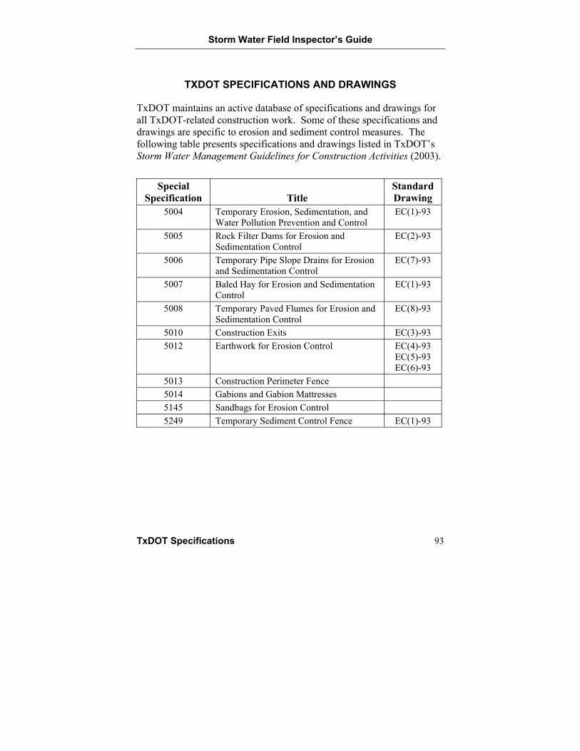
Storm Water Field Inspector’s Guide
TxDOT Specifications 93
TXDOT SPECIFICATIONS AND DRAWINGS
TxDOT maintains an active database of specifications and drawings for all TxDOT-related construction work. Some of these specifications and drawings are specific to erosion and sediment control measures. The following table presents specifications and drawings listed in TxDOT’s Storm Water Management Guidelines for Construction Activities (2003).
Special Specification Title
Standard Drawing
5004 Temporary Erosion, Sedimentation, and Water Pollution Prevention and Control
EC(1)-93
5005 Rock Filter Dams for Erosion and Sedimentation Control
EC(2)-93
5006 Temporary Pipe Slope Drains for Erosion and Sedimentation Control
EC(7)-93
5007 Baled Hay for Erosion and Sedimentation Control
EC(1)-93
5008 Temporary Paved Flumes for Erosion and Sedimentation Control
EC(8)-93
5010 Construction Exits EC(3)-93 5012 Earthwork for Erosion Control EC(4)-93
EC(5)-93 EC(6)-93
5013 Construction Perimeter Fence 5014 Gabions and Gabion Mattresses 5145 Sandbags for Erosion Control 5249 Temporary Sediment Control Fence EC(1)-93


Storm Water Field Inspector’s Guide
References 95
REFERENCES

Storm Water Field Inspector’s Guide
References 97
REFERENCES
Brauer, C. and Foster, A. 2004. Video Conference on Completing the Construction Storm Water Pollution Prevention Plan (SW3P) Field Inspection and Maintenance Report. TxDOT.
Keller, G., and J. Sherar. 2003. Low-Volume Roads Engineering, Best Management Practices Field Guide. U.S. Department of Agriculture, Forest Service.
Landphair, H., J. A. McFalls, and D. Thompson. 2000. Design Methods, Selection, and Cost-Effectiveness of Stormwater Quality Structures. Texas Transportation Institute Report 1837-1. College Station, Texas.
North Central Texas Council of Governments (NCTCOG). 1993. Storm Water Quality Best Management Practices for Residential and Commercial Land Uses. Arlington, Texas.
Texas Commission on Environmental Quality (TCEQ). 1999. Complying with the Edwards Aquifer Rules: Technical Guidance on Best Management Practices. Austin, Texas.
Texas Department of Transportation (TxDOT). 2004. TxDOT 1993 Special Specifications Database. URL: http://www.dot.state.tx.us/ business/specifications.htm. March 29, 2004.
Texas Department of Transportation (TxDOT). 2004. TxDOT Temporary Erosion Standard Drawings. Design Division. URL: http://www.dot.state.tx.us/insdtdot/orgchart/cmd/cserve/standard/rdwylse.htm. March, 29 2004.
Texas Department of Transportation (TxDOT). 2003. Storm Water Management Guidelines for Construction Activities. Environmental Affairs Division, Water Resources Management Branch, and Division of Bridges and Structures, Hydraulics Section. Austin, Texas.
Urban Drainage and Flood Control District. 1992. Urban Storm Drainage Criteria Manual, Volume 3 – Best Management Practices,
Storm Water Field Inspector’s Guide
98 References
Stormwater Quality. Urban Drainage and Flood Control District, Denver, Colorado.
Virginia Department of Conversation and Recreation (VDCR). 1992. Virginia Erosion and Sediment Control Handbook. Division of Soil and Water Conservation. Richmond, Virginia.


![Modifications Inquiry Inspector's report [250kb] (pdf document)](https://img.pdfslide.net/doc/110x75/58522c581a28abfa398d34a3/modifications-inquiry-inspectors-report-250kb-pdf-document.jpg)