Embed Size (px)
Citation preview

Vol.:(0123456789)1 3
Journal of Dynamic Behavior of Materials https://doi.org/10.1007/s40870-021-00298-4
RESEARCH PAPER
Strain Rate Sensitivity of the Additive Manufacturing Material Scalmalloy®
P. Jakkula1 · G. Ganzenmüller1,2 · F. Gutmann1,2 · A. Pfaff2 · J. Mermagen2 · S. Hiermaier1,2
Received: 25 June 2020 / Accepted: 22 March 2021 © The Author(s) 2021
AbstractThis work investigates the influence of strain rate on the stress/strain behaviour of Scalmalloy. This material is an aluminium–scandium–magnesium alloy, specifically developed for additive manufacturing. The bulk yield stress of the material processed by Selective Laser Melting is approximately 340 MPa which can be increased by heat-treating to approximately 530 MPa. These numbers, combined with the low mass density of 2.7 g/cm3, make Scalmalloy an interesting candidate for lightweight crash-absorbing structures. As this application is inherently dynamic, it is of interest to study the loading rate sensitivity, which is difficult to predict: Al–Sc alloys exhibit classic strain rate sensitivity with an increased yield stress at elevated strain rates. However, Al–Mg alloys are known to show the contrary effect, they exhibit less strength as strain rate is increased. To answer the question how these effects combine, we study the dynamic behaviour at four different strain rates ranging from 10−3 to 1000 /s using servo-hydraulic and split-Hopkinson testing methods. The resulting data is analysed in terms of strain rate sensitivity of tensile strength and failure strain. A constitutive model based on a simplified Johnson–Cook approach is employed to simulate the tensile tests and provides good agreement with the experimental observations.
Keywords Aluminium alloy · Dynamic testing · Additive manufacturing · Split-Hopkinson methods
Introduction
Additive manufacturing (AM) of metal structures allows for producing complex parts with tailored properties. These parts inherit their mechanical behaviour not only from the base material, but also from structural design choices, on a meso-scale between the metal microstructure length scale and the overall dimensions of the parts [1–3]. This allows for the design of light-weight, high-strength structures, and these are increasingly used for safety-relevant applications in aerospace and automotive engineering [4–8]. In these appli-cations, dynamic loading due to crash and impact are rou-tinely encountered. It is therefore a necessary requirement
to know the strain-rate dependency of the base material to quantify crashworthiness.
This work considers the Scandium modified Alumin-ium-Magnesium alloy AA5028, which is commercialized by APworks and sold under the trade name Scalmalloy. According to the manufacturer, it is based on the 5xxx series AlMg alloys with an Mg content of 3.2–4.8 wt% and Sc 0.02–0.04 wt% [9]. While the current work does not consider microstructural analysis, related data may be found in [10]. The addition of Scandium increases strength and improves weldability [11]. The bulk yield stress of the as-built mate-rial is approximately 350 MPa which can be increased by heat-treating to approximately 550 MPa [9]. These numbers, combined with the low mass density of 2.7 g/cm3, make AA5028/Scalmalloy an interesting candidate for lightweight crash-absorbing structures. Its strain-rate sensitivity, how-ever, is difficult to predict.
Al–Sc alloys exhibit classic strain rate sensitivity with an increased yield stress at elevated strain rates [12]. In con-trast, Al–Mg alloys are known to show the contrary effect, they exhibit negative strain rate sensitivity, at least up to moderate strain rates of 103 /s [13]. To answer the question how these effects combine in AA5028, we study its dynamic
* G. Ganzenmüller [email protected]
1 Albert-Ludwigs-Universität Freiburg, Sustainable Systems Engineering, INATECH, Emmy-Noether Str. 2, 79110 Freiburg, Germany
2 Fraunhofer Institute for High-Speed Dynamics, Ernst-Mach-Institut, EMI, Ernst-Zermelo Str. 4, 79104 Freiburg, Germany

Journal of Dynamic Behavior of Materials
1 3
behaviour at four different strain rates ranging from 10−3 to 1000 /s using servo-hydraulic and split-Hopkinson testing methods. Both as-built and heat-treated specimens are inves-tigated, and the resulting data is analysed in terms of the strain-rate dependency of Ultimate Tensile Strength (UTS) and strain at failure. Finally, a simplified Johnson–Cook material model is parametrized to reproduce the experimen-tal findings, allowing for the simulation of dynamic loading events.
Materials and Methods
Specimens
A total of 60 raw stock cylinders with dimensions of ø 20 × 120 mm2 were produced from a single feedstock by a commercial Laser Beam Melting system (EOS M 400), equipped with a 1 kW laser unit (YLR-series, Continuous Wave (CW)-laser, wavelength 1070 nm). The specimens were printed in a 90 degree orientation to the build plate. All objects were manufactured with 60 μm layers with a heated building platform (40 °C). Half of the batch was subjected to a heat treatment of 325 °C for 4 h, following the powder manufacturer’s (APworks) recommendation. The final speci-men geometry, according to Fig. 1, was then obtained by CNC machining. This particular specimen geometry was chosen over a standardized geometry to work well with the constraints of our split-Hopkinson tension bar.
Quasi‑static and Low Strain Rate Testing
Tensile testing for the strain rates 0.001 /s, 0.1 /s, and 10 /s were performed using a servo-hydraulic testing machine (Instron 8801), equipped with a 50 kN load cell (Dynacell). Testing was performed in displacement controlled mode with constant cross-head velocities. Nominal specimen
strain was evaluated using Digital Image Correlation (2D-DIC, GOM Correlate software) with a resolution of 1 pixel = 0.026 mm. A fine speckle pattern with approximate speckle sizes of 0.1 mm was produced with an airbrush gun. A DIC-based virtual extensometer was defined over a gauge length of 12 mm, i.e., contained entirely within the parallel gauge region. In this way, nominal strain could be evaluated up to the point of failure. From prior experience, the accuracy of the nominal strain measurement is better than 2% of the indicated value. Additionally, we evaluated the local strain in the necking region. This, however, was only possible for small local strains, as DIC then failed to correctly track deformation field. The beginning of devia-tion between local strain and extensometer strain was used to define necking strain, i.e., the end of uniform elongation. Deformation images were recorded using a high speed cam-era (Photron SAZ) with 1024 × 1024 resolution at 35 fps to 6000 fps, depending on the strain rate. In the following, we always report nominal (engineering) stress, i.e., the ratio of force over the initial value of the specimen’s gauge length cross-section.
Dynamic Strain Rate Testing
The split Hopkinson tension bar (SHTB) used here is sketched in Fig. 2 and described in detail in [14]. Compared to other SHTBs, this setup is optimized for low velocities, low forces and a long pulse duration of 1.2 ms. Force is measured via a pair of conventional strain gauges mounted on the output bar, connected diagonally in a Wheatstone bridge circuit to eliminate bending information. The Wheat-stone bridge circuit is driven in constant voltage mode and its output is increased by a factor of 100 using an ampli-fier with 1 MHz bandwidth. This signal is recorded by a data acquisition (DAQ) card operating at 10 MHz and 16 bit resolution. The conversion factor from strain to force is established via a calibration procedure, wherein a dedicated force sensor is placed between input and output bars, while
Fig. 1 Specimen geometry with cylindrical gauge region ø 4 × 15 . All dimensions are in mm

Journal of Dynamic Behavior of Materials
1 3
a static load is applied onto the bars. The signal of the force sensor is recorded using the same amplifier and data acquisi-tion card as during a real experiment. The force sensor, in turn is calibrated against the already calibrated load cell in the universal testing machine described above. Thus, the entire force measuring system consisting of strain gauges, amplifier and DAQ card is calibrated, which compensates for any eventual misalignment of the strain gauges or similar constant systematic errors.
The loading pulse generated in the input bar from the impact of the striker to the flange, gives the long pulse dura-tion of 1.2 ms as shown in Fig. 3A. High-Speed video imag-ing of the sample is employed (Photron SAZ, 640 × 280 pixels, frame rate 100 kHz, 1 px = 0.067 mm) for subsequent optical strain analysis by 2D DIC. Shortly before perform-ing the experiment, a speckle pattern with white and black spray paint was applied to the specimen gauge section in order to provide the necessary contrast for the DIC analysis. The specimens were then directly threaded into the bar ends
and torqued to 10 Nm. The experiment was then conducted by firing the striker against the input flange at a velocity suitable to reach a nominal strain rate of 1000 ± 100 /s in the sample gauge section. Specimen strain was computed from DIC in the same manner as for the lower strain rates. We note that, due to the rise time of the loading pulse, the target strain rate of 1000 /s is reached after the yield point, see Fig. 3B.
Data Reduction
Figure 4 shows the nominal stress/strain curves obtained for all combinations of strain rate and specimen type: as-built (untreated) and heat-treated. Each testing series consists of N = 5 experiments. Within one series, the individual experi-ments exhibit very little scatter. The characteristic properties ultimate tensile strength, �max and strain at failure, �f are represented using straightforward averages and uncertainty
Fig. 2 Sketch of the SHTB setup employed in this work. All dimen-sions in mm. Input and output bars are 16 mm diameter aluminium rods. The striker is a hollow aluminium tube of 40 mm outer diameter
and 20 mm inner diameter. Two strain gauges stations on the input bar and output bar measure the incident wave, �
inc , and transmitted
wave, �tra
Fig. 3 a Raw data from strain gauge 1 (incident pulse) and strain gauge 2 (transmitted pulse) for an as-built Scalmalloy specimen. b Evolution of nominal strain rate in the specimen’s gauge region as computed by DIC

Journal of Dynamic Behavior of Materials
1 3
estimates, e.g. for the strength: �̄�max =∑N
j=1𝜎max,j∕N and
s�
�̄�max�
=
�
∑N
j=1
�
𝜎max,j − �̄�max�2∕(N − 1).
Results
The nominal stress/strain graphs obtained by our experi-ments are shown in Fig. 4. Within one testing series, the individual curves are almost indistinguishable which we
attribute to the quality of our SLM process. At quasi-static rates of strain, obvious serrations in the curves are visible. These are presumably due to the Portevin-Le-Chatelier (PLC) effect, which describes the locking of a moving dis-location due to solute Mg atoms [13]. At higher strain rates, this effect diminishes as the diffusion speed of solute Mg becomes slow compared to the dislocation speed. Averages for ultimate tensile strength (the maximum of the nominal stress/nominal strain-curve), failure strain, yield strength and necking strain are reported in Table 1. Note that the
Fig. 4 Scalmalloy nominal stress–nominal strain plots at different strain rates ranging from 10−3 to 103 /s. Left and right columns are for as-built (non heat-treated) and heat-treated specimens, respectively. Note that each experiment set has 5 individual experiments which are shown with differ-ently coloured lines (Color figure online)

Journal of Dynamic Behavior of Materials
1 3
value of the strain rate at yield is uncertain for the SHTB experiment as yielding occurs during the rise of the load-ing pulse. Our quasi-static data is in agreement with prior work on Scalmalloy [10], where an UTS of 334 MPa and 540 MPa was reported for as-built and heat-treated speci-mens, respectively. The failure behavior is brittle for the heat-treated specimens, with almost no necking. As-built specimens exhibit limited necking. Here, the diameter at the failure location is 75% of the initial value.
Strain‑Rate Dependency
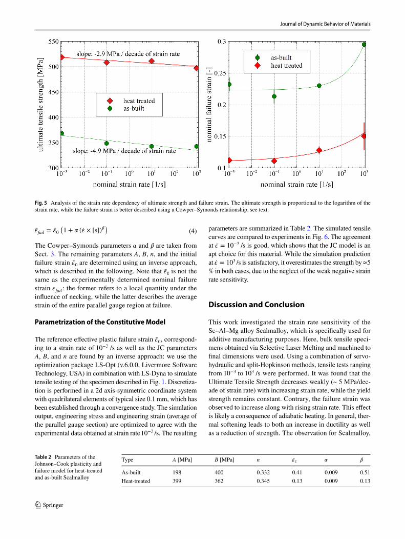
To quantify the strain rate sensitivity, the characteristic quantities given in Table 1 are analysed. The maximum stress is well represented by a relationship proportional to the negative logarithm of the strain rate:
The constant of proportionality is a = −4.9 ± 0.3 MPa, and a = −2.9 ± 0.3 MPa, for as-built and heat-treated Scalmal-loy, respectively. Uncertainty estimates are obtained from the residual error of the Levenberg–Marquardt algorithm used for data fitting. The dependence of the strain at failure on strain rate does not follow this simple Johnson–Cook type behaviour. Instead, a Cowper–Symonds relationship appears to better fit the data:
For as-built specimens, we find �fail,0 = 0.223 ± 0.005 , � = 0.009 ± 0.007 , and � = 0.51 ± 0.10 . For heat-treated Scalmalloy, we find �fail,0 = 0.109 ± 0.004 , � = 0.009 ± 0.007 , and � = 0.23 ± 0.13.
Within the experimental uncertainty, both the strain at the end of uniform elongation (beginning of neck formation) and the failure strain are unaffected in the strain rate interval 10−3 to 10 /s. At 103 /s, however, both strains increase. It is likely that this increase in ductility is the result of adiabatic
(1)𝜎max = 𝜎0 + a log(�̇�)
(2)𝜀fail = 𝜀fail,0(
1 + 𝛼 (�̇� × [s])𝛽)
heating. We conclude this section by noting that Scalmalloy exhibits a weak negative strain rate sensitivity for the UTS. The failure strain, however, increases along with the strain rate (Fig. 5).
Simulation Model
The data presented in Sect. 3 is employed to parametrize a simplified Johnson–Cook (JC) plasticity model in com-bination with an explicit Finite Element scheme LS-Dyna (v.11.0, Livermore Software Technology, USA). This JC model only accounts for isotropic hardening but no tem-perature effects. The strain-rate dependency of the yield-stress is disregarded as it is weak, but more importantly, negative. Softening with increasing strain-rate would lead to strong instabilities in explicit time integration schemes as it promotes localization and necking. Failure is addressed by deleting elements which exceed a given value of effec-tive plastic strain. The failure model is strain-rate sensitive according to the above determined Cowper–Symonds rela-tions, c.f. Eq. 2.
Constitutive Model
The constitutive model is based on isotropic linear elastic-ity with Young’s modulus E = 70 GPa and Poisson’s ratio � = 0.3 . These values are typical of Aluminium alloys and in agreement with experimental data on Scalmalloy [10]. We utilize a J2 plasticity model with radial return, based on the yield stress �y according to the simplified JC model:
Here, �̄� is the accumulated effective plastic strain. Failure is accounted for by deleting those elements which exceed the strain-rate dependent maximum effective plastic strain,
(3)𝜎y = (A + B �̄�n)
Table 1 Results for ultimate tensile strength �max
, failure strain �fail
, yield strength and necking strain at different strain rates considered in this work
Errors indicate one standard deviation
Strain rate Max. strength (MPa) Failure strain (%) Yield strength (MPa) Necking strain (%)
As-built 0.001 368.4 ± 1.1 23.2 ± 1.1 263.2 ± 4.2 17.8 ± 2.10.1 348.5 ± 1.2 21.3 ± 1.1 260.8 ± 3.3 16.5 ± 0.910 342.6 ± 0.9 23.0 ± 0.4 266.7 ± 1.2 15.9 ± 0.31000 342.5 ± 1.6 29.5 ± 0.4 269.0 ± 7.1 23.1 ± 1.3
Heat-treated 0.001 518.6 ± 0.5 11.2 ± 0.2 465.6 ± 1.2 10.3 ± 0.30.1 508.1 ± 1.3 11.1 ± 0.5 470.7 ± 3.6 10.2 ± 0.610 511.0 ± 1.5 12.8 ± 0.6 462.8 ± 1.8 10.8 ± 0.81000 497.0 ± 3.0 15.0 ± 2.2 477.0 ± 3.9 14.9 ± 0.1
Journal of Dynamic Behavior of Materials
1 3
The Cowper–Symonds parameters � and � are taken from Sect. 3. The remaining parameters A, B, n, and the initial failure strain �̄�0 are determined using an inverse approach, which is described in the following. Note that �̄�0 is not the same as the experimentally determined nominal failure strain �fail : the former refers to a local quantity under the influence of necking, while the latter describes the average strain of the entire parallel gauge region at failure.
Parametrization of the Constitutive Model
The reference effective plastic failure strain �̄�0 , correspond-ing to a strain rate of 10−3 /s as well as the JC parameters A, B, and n are found by an inverse approach: we use the optimization package LS-Opt (v.6.0.0, Livermore Software Technology, USA) in combination with LS-Dyna to simulate tensile testing of the specimen described in Fig. 1. Discretiza-tion is performed in a 2d axis-symmetric coordinate system with quadrilateral elements of typical size 0.1 mm, which has been established through a convergence study. The simulation output, engineering stress and engineering strain (average of the parallel gauge section) are optimized to agree with the experimental data obtained at strain rate 10−3 /s. The resulting
(4)�̄�fail = �̄�0(
1 + 𝛼 (�̇� × [s])𝛽) parameters are summarized in Table 2. The simulated tensile
curves are compared to experiments in Fig. 6. The agreement at �̇� = 10−3 /s is good, which shows that the JC model is an apt choice for this material. While the simulation prediction at �̇� = 103 /s is satisfactory, it overestimates the strength by ≈ 5 % in both cases, due to the neglect of the weak negative strain rate sensitivity.
Discussion and Conclusion
This work investigated the strain rate sensitivity of the Sc–Al–Mg alloy Scalmalloy, which is specifically used for additive manufacturing purposes. Here, bulk tensile speci-mens obtained via Selective Laser Melting and machined to final dimensions were used. Using a combination of servo-hydraulic and split-Hopkinson methods, tensile tests ranging from 10−3 to 103 /s were performed. It was found that the Ultimate Tensile Strength decreases weakly (~ 5 MPa/dec-ade of strain rate) with increasing strain rate, while the yield strength remains constant. Contrary, the failure strain was observed to increase along with rising strain rate. This effect is likely a consequence of adiabatic heating. In general, ther-mal softening leads to both an increase in ductility as well as a reduction of strength. The observation for Scalmalloy,
Fig. 5 Analysis of the strain rate dependency of ultimate strength and failure strain. The ultimate strength is proportional to the logarithm of the strain rate, while the failure strain is better described using a Cowper–Symonds relationship, see text.
Table 2 Parameters of the Johnson–Cook plasticity and failure model for heat-treated and as-built Scalmalloy
Type A [MPa] B [MPa] n �̄�0
� �
As-built 198 400 0.332 0.41 0.009 0.51Heat-treated 399 362 0.345 0.13 0.009 0.13

Journal of Dynamic Behavior of Materials
1 3
that UTS decreases slightly with strain rate, might therefore be the combined effect of both strain rate hardening—as encountered for many metals—and thermal softening. How-ever, the fact that yield stress is unaffected by strain rate, c.f. Table 1, suggests that Scalmalloy shows no strain rate hardening at constant temperature, as adiabatic heating is not relevant at initial yield. The experiments reported here can-not separate these effects in practice, so we have to restrict our finding to an apparent weak decrease in UTS. Additional experiments that quantify the effects of varying temperature at constant strain rate are required to resolve this ambiguity.
To demonstrate the practical applicability of the data reported here, a constitutive model based on the John-son–Cook plasticity model and a simple strain-rate depend-ent failure criterion was parametrized and shown to agree well with the experimental data.
This work addresses two important questions. From a practical point of view, this light-weight, yet high strength,
aluminium alloy lends itself for safety-relevant applica-tions which include crash and impact scenarios. Our work provides the necessary data and a model to design and simulate such structures, including the effects of strain rate. On the other hand, from a more scientific point of view, it is interesting to see how different strain rate effects of Sc and Mg combine in one aluminium alloy: for moder-ate strain rates <≈ 103 , the addition of Mg mainly leads to negative strain-rate sensitivity [13], while the addition of Sc incurs a pronounced positive strain rate sensitivity [15] for the UTS. For Scalmalloy, with alloying values of 4.4% Mg and 0.73% Sc by weight [10], these effects appear to mutually cancel out. We note that the observations made here only apply to strain rates of 1000 /s and below. One may speculate that, for even higher strain rates, a changeo-ver from positive to negative strain rate exists, as is the case for the Al–Mg 5021 alloy [16].
Fig. 6 Comparison between simulation results with the Johnson–Cook model (blue dashed curves) and the experimental data (red curves). The left column is for as-built Scalmalloy, the right column is for the heat-treated material (Color figure online)

Journal of Dynamic Behavior of Materials
1 3
Acknowledgements We acknowledge funding from Carl-Zeiss Foun-dation, grant title Skalenübergreifende Charakterisierung robuster funktionaler Materialsysteme.
Funding Open Access funding enabled and organized by Projekt DEAL.
Open Access This article is licensed under a Creative Commons Attri-bution 4.0 International License, which permits use, sharing, adapta-tion, distribution and reproduction in any medium or format, as long as you give appropriate credit to the original author(s) and the source, provide a link to the Creative Commons licence, and indicate if changes were made. The images or other third party material in this article are included in the article’s Creative Commons licence, unless indicated otherwise in a credit line to the material. If material is not included in the article’s Creative Commons licence and your intended use is not permitted by statutory regulation or exceeds the permitted use, you will need to obtain permission directly from the copyright holder. To view a copy of this licence, visit http:// creat iveco mmons. org/ licen ses/ by/4. 0/.
References
1. Chekurov S, Metsä-Kortelainen S, Salmi M, Roda I, Jussila A (2018) The perceived value of additively manufactured digital spare parts in industry: an empirical investigation. Int J Prod Econ 205:87–97. https:// doi. org/ 10. 1016/j. ijpe. 2018. 09. 008
2. Mitchell A, Lafont U, Hołyńska M, Semprimoschnig C (2018) Additive manufacturing-a review of 4D printing and future appli-cations. Addit Manuf 24:606–626. https:// doi. org/ 10. 1016/j. addma. 2018. 10. 038
3. Rashed MG, Ashraf M, Mines RAW, Hazell PJ (2016) Metallic microlattice materials: a current state of the art on manufacturing, mechanical properties and applications. Mater Design 95:518–533. https:// doi. org/ 10. 1016/j. matdes. 2016. 01. 146
4. Ozdemir Z, Hernandez-Nava E, Tyas A, Warren JA, Fay SD, Goodall R, Todd I, Askes H (2016) Energy absorption in lattice structures in dynamics: experiments. Int J Impact Eng 89:49–61. https:// doi. org/ 10. 1016/j. ijimp eng. 2015. 10. 007
5. Tsouknidas A, Pantazopoulos M, Katsoulis I, Fasnakis D, Maro-poulos S, Michailidis N (2016) Impact absorption capacity of 3D-printed components fabricated by fused deposition modelling. Mater Design 102:41–44. https:// doi. org/ 10. 1016/j. matdes. 2016. 03. 154
6. Li S, Zhao S, Hou W, Teng C, Hao Y, Li Y, Yang R, Misra RDK (2016) Functionally graded Ti–6Al–4V meshes with high strength
and energy absorption. Adv Eng Mater 18:34–38. https:// doi. org/ 10. 1002/ adem. 20150 0086
7. Tancogne-Dejean T, Spierings AB, Mohr D (2016) Additively-manufactured metallic micro-lattice materials for high specific energy absorption under static and dynamic loading. Acta Mater 116:14–28. https:// doi. org/ 10. 1016/j. actam at. 2016. 05. 054
8. Brennan-Craddock J, Brackett D, Wildman R, Hague R (2012) The design of impact absorbing structures for additive manu-facture. J Phys 382:012042. https:// doi. org/ 10. 1088/ 1742- 6596/ 382/1/ 012042
9. Vorel M, Hinsch S, Konopka M, Scheerer M (2017) AlMgSc alloy 5028 status of maturation 2017. p. 9 pages. Publisher: Proceed-ings of the 7th European Conference for Aeronautics and Space Sciences. Milano, Italy, 3-6 july 2017, https:// doi. org/ 10. 13009/ EUCAS S2017- 633
10. Koutny D, Skulina D, Pantělejev L, Paloušek D, Lenczowski B, Palm F, Nick A (2018) Processing of Al-Sc aluminum alloy using SLM technology. Procedia CIRP 74:44–48. https:// doi. org/ 10. 1016/j. procir. 2018. 08. 027
11. Royset J (2007) Scandium in aluminium alloys: physical metal-lurgy, properties and applications. Metall Sci Technol 25:2
12. Lee WS, Chen TH (2006) Dynamic mechanical response and microstructural evolution of high strength aluminum–scandium (Al–Sc) alloy. Mater Trans 47:355–363. https:// doi. org/ 10. 2320/ mater trans. 47. 355
13. Yamada H, Kami T, Mori R, Kudo T, Okada M (2018) Strain rate dependence of material strength in AA5xxx series aluminum alloys and evaluation of their constitutive equation. Metals 8:576. https:// doi. org/ 10. 3390/ met80 80576
14. Ganzenmüller GC, Blaum E, Mohrmann D, Langhof T, Plappert D, Ledford N, Paul H, Hiermaier S (2017) A simplified design for a split-Hopkinson tension bar with long pulse duration. Proc Eng 197:109–118. https:// doi. org/ 10. 1016/j. proeng. 2017. 08. 087
15. Lee WS, Chen TH (2008) Dynamic deformation behaviour and microstructural evolution of high-strength weldable aluminum scandium (Al–Sc) alloy. Mater Trans 49:1284–1293. https:// doi. org/ 10. 2320/ mater trans. MRA20 08032
16. Kami T, Yamada H, Ogasawara N (2018) Dynamic behaviour of Al–Mg aluminum alloy at a wide range of strain rates. EPJ Web Conf 183:02028. https:// doi. org/ 10. 1051/ epjco nf/ 20181 83020 28
Publisher’s Note Springer Nature remains neutral with regard to jurisdictional claims in published maps and institutional affiliations.


![A MODEL OF ENHANCED STRAIN RATE SENSITIVITY IN ...2 A.G. Sheinerman and S.V. Bobylev metals have been suggested. Prasad and Armstrong [17] suggested that strain rate sensitivity is](https://img.pdfslide.net/doc/110x75/60bf5ee16240a414c6338d3f/a-model-of-enhanced-strain-rate-sensitivity-in-2-ag-sheinerman-and-sv-bobylev.jpg)