Embed Size (px)
Citation preview

STREAM ALTERATION PRACTICES

SDC - 1
Stream Diversion Channel SDC
DEFINITION A temporary channel constructed to convey stream flow around in-stream construction. PURPOSE Stream diversion channels are used to allow in-stream work to be conducted separate from flowing water as required by Aquatic Resource Alteration Permits. CONDITIONS Linear projects, such as utilities or roads, frequently cross streams creating a potential for excessive sediment loss into a stream, by both the disturbance of the approach areas, and by the work within the streambed and banks. Disturbance within the confines of stream banks are required to be conducted “in the dry” or separate from flowing water. No excavation equipment should ever be operated in flowing waters. In cases where in-stream work is unavoidable, a stream diversion channel should be considered to prevent excessive
damage from sedimentation. To limit land-disturbance, overland pumping of the stream should be considered in low-flow conditions whenever possible. Some streams are too large to construct a diversion channel for. In those cases, consider the use of alternative structures in order for work to be conducted in dry conditions. Examples of alternative structures are cofferdams and geotextile tubes. The duration of use of the diversion should be minimized to the shortest period of time possible. Clearing of the streambed and banks should be kept to a minimum. Work that requires a stream diversion channel requires authorization from the Tennessee Division of Water Pollution Control and United States Army Corps of Engineers. For more information, see Appendix C and: http://www.state.tn.us/environment/permits/arap.htm
SDC - 2
DESIGN CRITERIA Professionals familiar with the design of water conveyance systems should prepare construction plans and drawings for this technique. Size: The bottom width of the stream diversion should be equal to the bottom width of the existing streambed, at a minimum. The capacity of the temporary channel should be designed to be equivalent to the bankfull capacity of the existing channel. Side Slopes: Side slopes of the stream diversion channel should be no steeper than 2:l. Depth and Grade: Depth and grade may be variable, dependent on site conditions, but should be sufficient to ensure continuous flow of water in the diversion. Channel Lining: See Figure 1. A stream diversion channel should be lined to prevent erosion of the channel and sedimentation in the stream. The lining is selected based upon the expected velocity of bankfull flow. Table 1 shows the selection of channel linings that may be used: turf reinforcement mat or sod – SDC-A; geotextile – SDC-B; or TDOT Class A-1 riprap and geotextile – SDC-C. Refer to specifications Riprap - RR, Matting – MA, and Geotextile – GE. Geotextile: Geotextiles should be used as a protective cover for soil or, if the channel is to be lined with riprap, as a separator between graded stone and the soil base. The geotextile will prevent erosion of the channel and the migration of soil particles from the subgrade into the graded stone. Care should be taken to place the geotextile in direct contact with the soil such that no void spaces exist between the underlying soil and the geotextile.
CONSTRUCTION SPECIFICATIONS 1. The channel should be excavated, and constructed with plugs at both ends. Plugs may be constructed of riprap, sandbags or sheet piling, or may be undisturbed soil left in place. See Figure 2.
2. Silt fence or a diversion berm should be placed along the sides of the channel to prevent unfiltered runoff from entering the stream. The diversion berm can be constructed using the material excavated for the stream diversion. Refer to specifications Silt Fence - SF or Diversion – DI.
3. The channel surface should be smooth (to prevent tearing of the liner) and lined with the material specified in the plans. The outer edges of the geotextile should be secured at the top of the channel with compacted soil.
4. The plugs are removed when the liner installation is complete, removing the downstream plug first.
5. As soon as construction in the streambed is complete and the streambed has been restored to its previous condition, the diversion should be replugged and backfilled. The liner may be inspected for damage and salvaged if possible.
6. Upon removal of the liner, the diversion channel should immediately be restored and properly stabilized. MAINTENANCE The stream diversion channel should be inspected at the end of each day to make sure that the stream flow control measures and construction materials are positioned securely. This will ensure that the work area stays dry and that no construction materials float downstream. All repairs should be made immediately.
Temporary Stream Diversion Channel Linings
0 - 2.5 ft./sec.
Acceptable Velocity Range
Table 1
G eotextile SDC-B 2.5 - 9.0 ft./sec.
TDOT Class A-1 Riprap and G eotextile SDC-C 9.0 - 13.0ft./sec.
Lining M aterials Sym bol
Turf Reinforcem ent M atting or Sod SDC-A

SDC - 3
Stream Diversion Channel Linings
Figure 1 Source: GA SWCC
SDC-A
TURF REINFORCEMENT MAT OR SOD
SDC-B
SDC-C
RIPRAP
GEOTEXTILE
GEOTEXTILE
** ENTRENCH SILT FENCE AND GEOTEXTILE IN SAME TRENCH.
* WIDTH OF EXISTING STREAM CHANNEL BOTTOM
*
*
*
**

SDC - 4
Stream Diversion Channel (perspective view)
Figure 2 Source: GA SWCC

TSC - 1
Temporary Stream Crossing - TSC
DEFINITION A temporary structure installed across a flowing stream or watercourse for use by construction equipment. PURPOSE This standard provides a means for construction vehicles to cross streams or watercourses without moving sediment into the stream, damaging the streambed or channel, or causing flooding. CONDITIONS All stream crossings require authorization from the Tennessee Division of Water Pollution Control and United States Army Corps of Engineers prior to construction. For more information, see Appendix C and: http://www.state.tn.us/environment/permits/arap.htm Structures may include bridges, round pipes, or pipe arches. Temporary stream crossings should be in place for less than one year,
and should not be accessible to the general public. DESIGN CRITERIA Professionals familiar with the hydraulic calculations necessary to accomplish the work should design stream crossing construction plans and drawings using sound engineering practices. Size: The structure may be sized large enough to convey the bankfull flow of the stream, typically flows produced by a 2-year, 24-hour frequency storm, with normal high water protection since the flood plain will become effective at the bankfull elevation. However, if the crossing is designed as a low-water crossing, provision must be made for additional overflow protection of the structure, to prevent washout during high flow events. Location: The temporary stream crossing should be perpendicular to the stream. Where approach conditions dictate, the crossing may vary up to 15º from the perpendicular.

TSC - 2
Overflow Protection: Structures should be protected from washout during periods of peak discharges by diverting high flows around or over the structures. Methods to be considered for washout protection may include elevation of bridges above adjacent flood plain lands, crowning of fills over pipes, or by the use of diversions, dikes or island type structures. Frequency and intended use, stream channel conditions, overflow areas, potential flood damage, and surface runoff control should be considered when selecting the type of temporary stream crossing to be used. Temporary Bridge Crossing - SC-B: A temporary access bridge causes the least erosion of the stream channel crossing when the bridge is installed and removed (See Figure 1). It also provides the least obstruction to flow and fish migration. Provided that the bridge is properly designed and appropriate materials are used, a temporary access bridge typically is long lasting and requires little maintenance. It may also be salvaged at project’s end and used again in the future. However, a temporary bridge crossing is generally the most expensive crossing to design and construct. It also creates the greatest safety hazard if not adequately designed, installed, and maintained. Temporary Culvert Crossing - SC-C: A temporary access culvert is the most common stream crossing. It can control erosion effectively, but can cause erosion when it is installed and removed. A temporary culvert can be easily constructed and enables heavy equipment loads to be used. However, culverts create the greatest obstruction to flood flows and are subject to blockage and washout. The crossing may be designed based on the stream flows resulting from a 2-year, 24-hour frequency storm, in which case, Class A or B riprap may be used for normal erosion protection of the aggregate fill, and the roadbed would be at the elevation of the top of the banks. For temporary crossings of streams with large watersheds, the crossing may also be designed based on the low-flow channel conditions as a low water crossing. The culvert size would be adequate to convey base flows, but high water events
would overtop the structure and make the crossing temporarily unusable. Additional erosion protection of the fill would be necessary for this design, in the form of Class C or larger riprap to prevent the washout of the culverts. CONSTRUCTION SPECIFICATIONS All Crossings
1. In-stream work should be performed in dry conditions. Utilize a stream diversion channel or cofferdams to provide dry conditions for conducting the work. Refer to specification Stream Diversion Channel – SDC. Clearing of the streambed and banks should be kept to a minimum.
2. All surface water from the construction site should be diverted onto undisturbed areas adjoining the stream. Unstable stream banks should be lined with riprap or otherwise appropriately stabilized.
3. The crossing alignment shall be at right angles to the stream. Where approach conditions dictate, the crossing may vary up to 15º from a line drawn perpendicular to the centerline of the stream at the intended crossing location.
4. The centerline of both roadway approaches should coincide with the crossing alignment centerline for a minimum distance of 50 feet from each bank of the waterway being crossed. If physical or right-of-way restraints preclude the 50 feet minimum, a shorter distance may be provided. All fill materials associated with the roadway approach shall be limited to a maximum height of 2 feet above the existing flood plain elevation.
5. A water diverting structure such as a waterbar diversion should be constructed (across the roadway on both roadway approaches) 50 feet (maximum) on either side of the waterway crossing. This will prevent roadway surface runoff from directly entering the waterway. The 50 feet distance is measured from the top of the waterway bank. If the roadway approach is constructed with a reverse grade away from the waterway, a separate diverting structure is

TSC - 3
not required. Refer to specification Diversion – DI.
6. The crossing structure should be removed as soon as it is no longer necessary for access. During structure removal, utilize a stream diversion channel or cofferdams to provide dry conditions for conducting the work.
7. Upon removal of the crossing structure, the stream should immediately be restored to its original cross-section and properly stabilized.
Temporary Bridge Crossing - SC-B
1. The temporary bridge should be constructed at or above bank elevation to prevent the entrapment of floating materials and debris.
2. Abutments should be placed parallel to the stream and on stable banks.
3. Bridges should be constructed to span the entire channel. If the channel width exceeds eight feet (as measured from the tops of the banks), a temporary footing, pier, or bridge support may be constructed within the waterway.
4. Decking materials should be of sufficient strength to support the anticipated load. Decking materials must be butted tightly to prevent any soil material tracked onto the bridge from falling into the waterway below.
5. Bridges should be securely anchored at only one end using steel cable or chain. This will prevent channel obstruction in the event that floodwaters float the bridge. Large trees, large boulders, or driven steel anchors can serve as anchors.
Temporary Culvert Crossing - SC-C
1. All culverts must be strong enough to support their cross-sectioned area under maximum expected loads.
2. The invert elevation of the culvert should be installed on the natural streambed grade at both ends.
3. A geotextile should be placed on the streambed and stream banks prior to the placement of the pipe culvert(s) and aggregate. The geotextile will prevent the migration of soil particles from the subgrade into the graded stone. The geotextile should cover the streambed and extend a minimum of six inches and a maximum of one foot beyond the end of the culvert and bedding material. Refer to specification Geotextile – GE.
4. The culverts should extend a minimum of one foot beyond the upstream and downstream toe of the aggregate placed around the culvert.
5. The culvert(s) should be covered with small riprap, such as TDOT Class A-1. The depth of riprap above the top of the culvert should be one-half the diameter of the culvert or 18” whichever is greater. 6. Multiple culverts should be separated by one-half the diameter of the culvert or 12”, whichever distance is greater. A final layer of coarse aggregate, such as TDOT #57, should be applied to minimum depth of 6-inchs. MAINTENANCE The structure should be inspected after every rainfall and at least once a week, and all damages repaired immediately. The structure should be removed immediately after construction is finished, and the streambed and banks must be stabilized and restored to pre-construction conditions.

TSC - 4
Temporary Bridge Crossing – SC-B
Figure 1
Source: Maryland Water Resources Administration

TSC - 5
Temporary Culvert Crossing – SC-C
Figure 2
Source: TDOT English Standard Drawings
MINERAL AGGREGATE(SIZE 57) AT 6” THICK
CAPACITY OF CULVERTS SHALLBE ADEQUATE TO CONVEY THEDESIGN FLOW
SBS - 1
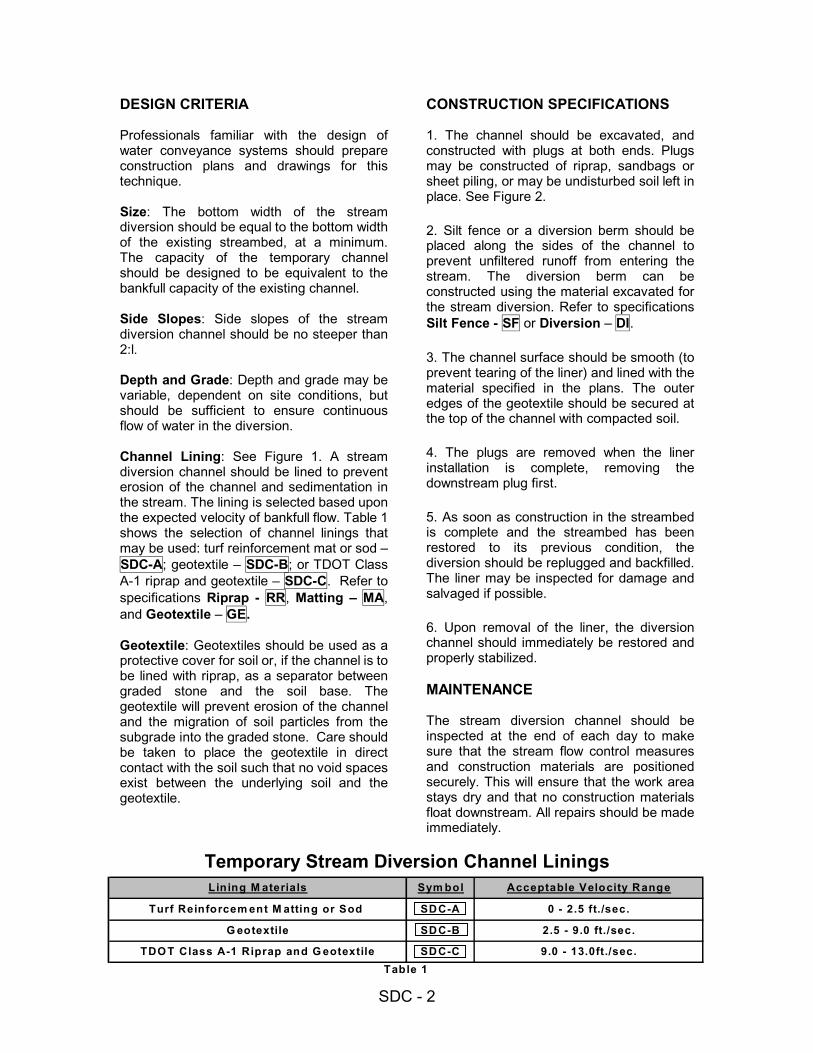
Bioengineered Stream Bank Stabilization - SBS
DEFINITION
The use of readily available native plant materials to maintain and enhance stream banks; or to prevent, or repair and restore small stream bank erosion problems.
PURPOSE
• Trap sediment from adjacent land • Form a root mat to stabilize and
reinforce the soil on the stream bank • Provide wildlife habitat • Enhance the appearance of the stream • Lower summertime water temperatures
providing a healthy aquatic environment
DESIGN CRITERIA Bioengineering is a stream bank stabilization technique that uses natural materials such as grasses, shrubs, trees, roots, and logs to divert water away from eroding banks, and stabilize the bank. Bioengineering is the preferred method of stream bank stabilization, and is permitted without notification where no work is done in stream
with mechanized equipment; and where the work is done in accordance with an approved bioengineering plan from the United States Department of Agriculture, Natural Resource Conservation Service (NRCS). Stream bank stabilization without an NRCS approved plan requires authorization from the Tennessee Division of Water Pollution Control and may require authorization from the United States Army Corps of Engineers. For more information, see Appendix C and: http://www.state.tn.us/environment/permits/arap.htm SELECTED MEASURES
Careful thought, planning and execution are required to assure that the stream bank stabilization project will be successful and long living. Revegetation includes seeding and sodding of grasses, seeding grasses in combination with erosion control fabrics, and the planting of woody vegetation (shrubs and trees). Refer to specifications Disturbed Area Stabilization

SBS - 2
Area Stabilization (With Sod) - SO, andBuffer Zone - BF.
Use erosion control blankets to aid in soilstabilization and revegetation. Refer tospecification Erosion Control Blanket/Matting- MA.
Live Stake: Fresh, live cut woody plantcuttings are driven into the ground as stakes,intended to root and grow into mature shrubsthat will stabilize soils and restore the riparianzone habitat. Live stakes provide no immediatestream bank stabilization. Only certain speciesof woody plants will work well for thisapplication. Willow species work best. SeeFigure 1.
Live Stake
Figure 1
Note: The following information applies toall of the figures in this standard:
Rooted/leafed condition of the living plantmaterial is not representative at the time ofinstallation. Source of all figures: GASWCC
Live stakes may also be driven into riprapprotected banks to help with permanentstabilization, and improve aesthetics.
Live Fascine: Live fascines are sausage-likebundles of live cut branches placed intotrenches along the stream bank. See Figure 2.They provide immediate protection from erosionwhen properly used and installed. Willowspecies work best.
Live fascines create very little site disturbanceas compared to other systems and works
especially well when combined with surfacecovers such as jute mesh or coir fabrics.
Live Fascine
Figure 2
Brushmattress: A combination of living unitsthat forms an immediate protective surfacecover over the stream bank. See Figure 3.Living units used include live stakes, livefascines, and a mattress branch cover (long,flexible branches placed against the banksurface).
Brushmattreses require a great deal of livematerial, and are complicated as well asexpensive to evaluate, design, and install.
Brushmatresses capture sediment during floodconditions, produce habitat rapidly, and quicklydevelop a healthy riparian zone.
Brushmattress
Figure 3
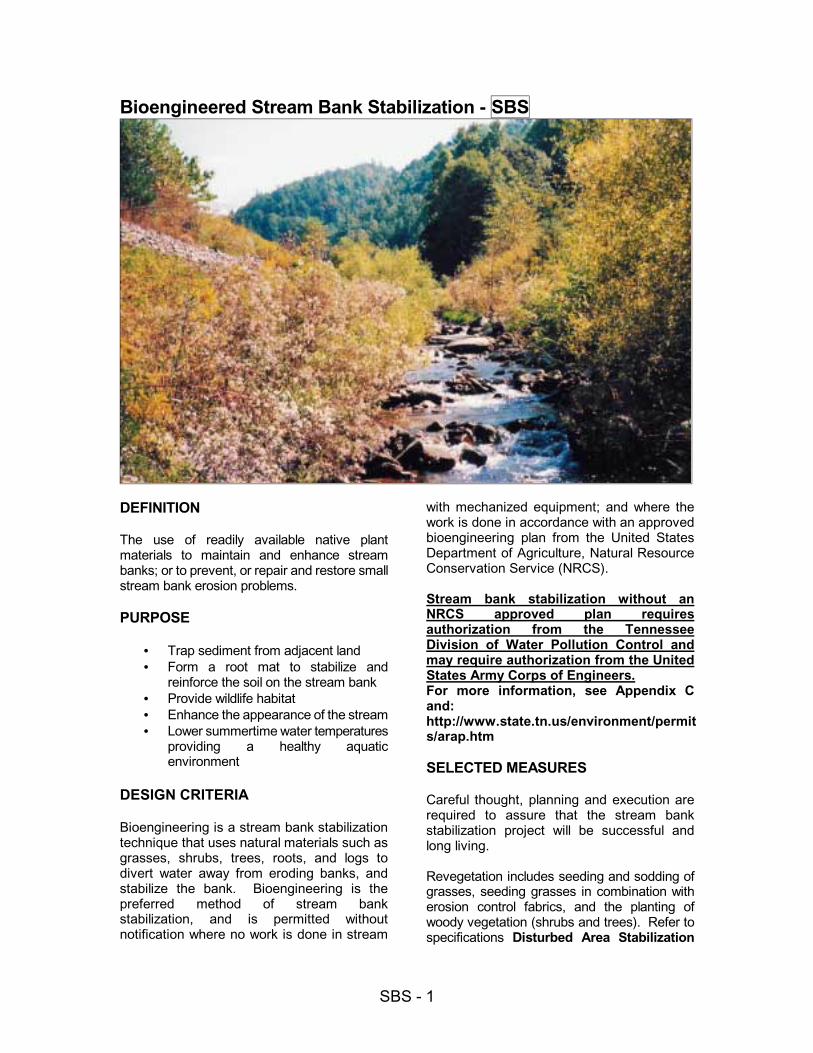
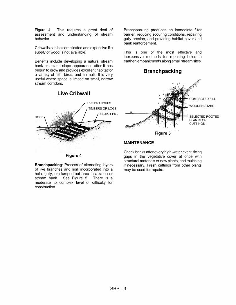
Live Cribwall: A rectangular framework of logsor timbers, rock, and woody cuttings. See
LIVE CUTTINGS
LIVE BRANCHES
WOODEN STAKE
LIVE STAKETWINE
LIVE BRANCHES
LIVE BRANCHES
WOODENSTAKE
LIVE STAKE
LIVEFASCINE
SBS - 3
Figure 4. This requires a great deal of assessment and understanding of stream behavior.
Cribwalls can be complicated and expensive if a supply of wood is not available.
Benefits include developing a natural stream bank or upland slope appearance after it has begun to grow and provides excellent habitat for a variety of fish, birds, and animals. It is very useful where space is limited on small, narrow stream corridors.
Live Cribwall
Figure 4
Branchpacking: Process of alternating layers of live branches and soil, incorporated into a hole, gully, or slumped-out area in a slope or stream bank. See Figure 5. There is a moderate to complex level of difficulty for construction.
Branchpacking produces an immediate filter barrier, reducing scouring conditions, repairing gully erosion, and providing habitat cover and bank reinforcement.
This is one of the most effective and inexpensive methods for repairing holes in earthen embankments along small stream sites.
Branchpacking
Figure 5
MAINTENANCE
Check banks after every high-water event, fixing gaps in the vegetative cover at once with structural materials or new plants, and mulching if necessary. Fresh cuttings from other plants may be used for repairs.
LIVE BRANCHES
TIMBERS OR LOGS
SELECT FILLROCK
COMPACTED FILL WOODEN STAKE SELECTED ROOTED PLANTS OR CUTTINGS