Embed Size (px)
Citation preview

;.;,v-:.

% mn to
X903
7? zibets.

Cornell University Library
arV19438
Strength and calculation of dimensions o
3 1924 031 247 624olln.anx
J
A

Cornell University
Library
The original of this book is in
the Cornell University Library.
There are no known copyright restrictions in
the United States on the use of the text.
http://www.archive.org/details/cu31924031247624

STRENGTH
CALCULATION OF DIMENSIONS
IRON AND STEEL CONSTRUCTIONS,
WITH
REFERENCE TO THE LATEST EXPERIMENTS.
TRANSLATED FROM TEE GERMAN
J. J. WEYRAUCH, PH. D.,
Prof., Polytechnic School of Stuttgart.
WITH FOUR FOLDING PLATES.
NEW YORK:D. VAN NOSTRAND, PUBLISHER,
23 Murray St., and 27 Warren St.
1877.

A-ifcGdS^
COPYRIGHT.
1877.
Bt D. VAN NOSTRAND.
PREFACE.
Many experiments have been lately made in Germany,
England, Sweden, and America, to determine the properties of
iron and steel. We propose to give in this brochure a general
view of the results obtained, and of their consequences, with-
out much detail, but so complete as to place practical engineers
at the present stand-point of critical judgment.
These experiments show (what every one admits) that the
methods hitherto employed in calculating the dimensions of
iron and steel constructions have been entirely wrong ; and that
the security of structures, in which their results have been
applied, though with great expenditure of material, is much
less than supposed.
Several methods for attaining better results have been
projected ; one of which was adopted by the Bavarian
Government. The brief sketch of the several methods, given
in the Appendix, shows that Launhardt's deserves the pre-
ference. This is so obvious, and meets with so few objec-
tions, that it is unsatisfactory only because of its limited
application. A formula like that of Launhardt was needed
for the case of resistance to alternating tenison and compres-
sion. Such a formula is here deduced. With it we have all
the requisites for a simple and rational determination of
dimensions. It is to be hoped that no one will wait to consider
it until more bridges are destroyed.
The chief reason that no one of the new methods has been
generally employed is, that no one of them is complete. It
would be impossible to determine fully the dimensions of a
bridge by the use of any one of them, except by the addition
of deductions specially made in each case. For this the workr
ing engineer has no time.
The systematic and final investigation here presented also
includes the cases, so far unconsidered, which occur under
shearing stress. Very particular regard is given to the sub-
ject of rivet-connections.
The ordinary methods of static calculation are not changed
by the new method. Those who prefer graphic solutions will
find all that is necessary for the complete determination of
stresses after completion of the diagram of forces.
The new formulas are based upon Wohler's law ; but the
special results of his tests must be applied with judgment ;
—
no more reliance being placed upon them than upon those of
Eondelet or Brunei under the old methods. General formulas,
old or new, do not change because of new experiments.
In the calculations especial reference is had to bridge and
building constructions, in which permanent duration is re-
quired. Consideration of the special resistances and experience
will serve to determine the co-efficients of safety.
CONTENTS.
General Properties. Dimensions.SEC. PAGE
1 Wohler's Law 8
2 Remarks oh W5hler's Law 11
3 Launhardt's Formula 12
4 Eormula for Alternating Tension and Compression 15
5 Ultimate Resistance to Tension and Compression 17
6 Excess of Elastic Ltait 21
7 Mechanical Treatment; Annealing; Hardening 24
8 Effect of Form 26
9 Percentage of Carbon, &c 28
10 Influence of Temperature 33
11 Further Results 38
12 Examination of Metals. . 40
13 Permissible Strain 43
"Wrought Iron 43
Steel 45
Remarks 46
14 The Calculation of Dimensions 49
Trusses 49
Simple Plate Beams 51
Continuous Girders 52
Shearing Strength. Riveting.
15 Ultimate Shearing Strength 57
16 Permisssible Shearing Stress 59
"Wrought Iron 60
Steel 61
Remarks 61

6
SEC. PAGE
17 Web of Plate Girders 62
18 Method of Riveting •. 65
19 Elastic Relations 69
20 Total Section and Number of Rivets 72
Remarks 74
21 Indirect Transmission of Force 75
22 Riveting of Bars 77
23 Riveting of Entire Plates 81
24 Rivetina; of Plate Girders 85
25 Flange-Riveting of Truss Girders 89
26 Riveting of Lattice Girders with Vertical Plates 93
27 Connections at Joints 96
Appendix.
28 The Methods of Gerber, Miiller and Schaffer 100
29 Remarks upon these Methods 105
30 Comparison of the Methods 109
The following authorities are the sources from whichProf. Weyrauch has obtained his data
:
Kavier, Resume des lecons, &c, Paris, 1826.
Morin, Resistance des materiaux, Paris, 1853.
Kirkaldy, Results of an experimental inquiry, London, 1862.
W5HLER, Ztschr. f. Bauwesen, 1860, 1863, 1866, 1870 ; W5hler,die Festigkeitsversuche mit Eisen und Stahl, Berlin, Ernst u. Korn,1870.
Clebsch, Theorie der Elasticity fester Korper : WtJlmter, Ex-perimentalphys.
Spangenberg, TJeber das Verhalten der Metalle bei wiederholten
Anstrengungen. Translated and published by Van Nostrand.Lahnhardt, die Inanspruchnahme des Eisens, Ztschr. d. HannOv
Arch. u. Ing. Vereins, 1873, S. 139.
Bauschinger, Mittheil., Ztschr. d. Bair. Arch. u. Ing. Vereins.
Kntjt Styite, Iron and Steel. Translated by Sandberg.
Fairbairn, Die eisernen Trager. Dtsch. v. Brauns, Braunschweig.
Kupfjfer, Recherchesexp.surl'elast. desMe'taux, St. Petersbourg,
1860.
Von Kaven Oollectaneen.
Tietze Ergebnisse der Schlagprobe, Techn . Blatter, 1874, S. 120.
Ko'fke, Ueber d. Fest. eingedrehter Axen, HannOv. Ztschr. 1864.
Fairbairn, die eisernen Trager dtsch. v. Brenner, 1859.
Benedict, Ueber d. Definition v. Schmiedeesen und Stahl, Ztschr.
d. Ostr. Ing. u. Arch. Vereins, 1875.
Vickers, Resistance de l'acier, relat. aux diff. prop, de carbone
qu'il cont., Bull, de la soc. d'encourag. 1863, Bd. X, S. 561.
Bauschinger, Versuche iiber d. Fest. des Bessemerstahls v. ver-
schied. Kohlenstoffgehalt, Ztschr. d. Bair, Arch. u. Ing. Vereins,
1873, S. 81.
Greiner, Ueber phosphorhalt. Stahl, Dinglers Polyt. Journ. 1875,
Bd. 217 S. 33, aus Revue univers. Bd. XXXV S. 613.
Robert L. Haswell, Studien iiber Bessemerstahl, Technische
Blatter, 1874, S. 111.
Fairbairn, Useful information for Engineers, London, 1860 ; Onthe tensile Strength of Wrought Iron at various Temperatures in
Transact, of the Brit. Assoc, 1856, S. 405; Engineering, 1871, p. 82.
Wertheim in Poggendorff Bd. LXXVIII.
Tabellen bei v. Kavest, Ztschr. d. HannOv. Arch. u. Ing. Vereins,
1868.
Ritter, Elem. Theorie u. Berech. eis. Dach. u. Briickenconstr.
Laissle u. Schctbler, der Bau der Briickentrager.
Weyratjch, A.llg. Theorie u. Berechn. d. cont. u. einfachen
Trager, 1873.
Winkler, die Lehre v. d. Elastizitat und Festigkeit.
Batjschinger, Versucbe uber die Zugfest. u. Schubfest. von Kes-
selblech u. Walzeisen. Ztschr. d. Bair. Arch. u. Ing. Vereins, 1873.
Walter R. Browne, Punched and Drilled Rivet-holes, Engineer,
1872.
Ltjdewig, Ueber Vernietungen, Zeitschrift des Vereins deutscher
Ingenieure, 1869, 1872.
Gerber, Berechn. d. Brilckentr. nach System Pauli, Ztschr. d.
Ver. dtsch. Ing. 1865, S. 480.
Schwedler, Ueber Nietverbindungen, Dtsch. Bauzt. 1867, S. 451.
Theune, Ueber das Verhalten elastiger Platten bei unsymmetris-
cher Inanspruchnahme. Dtsch. Bauzeit. 1874, S. 76.
Gerber, Bestimmung der zulassigen Spannung in Eisenconstruc-
tionen, Ztschr. d. Bair. Arch. u. Ing. Vereins, 1874, 8. 101.
Schaefer, Bestimmung der zulassigen Spannung fttr Eisencon-
structionen, Erbkams Ztschr. f. Bauwesen, 1874, S. 398.
G. M/uller, Zulassige Inanspruchnahme des Schmiedeeisens bei
Briickenconstructionen, Ztschr. des Oestr. Ing. u. Arch. Vereins,
1873, S. 197.
Gleim; der Amerik. Briickenbau der Neuzeit; Ztschr. d. Hannov.Arch. u. Ing. Vereins, 1876, S. 73.
ERRATAPage 17, in heading, for proof, read ultimate.
" 18, line 11, after anotlier piece, insert from the web.
" 21, line 3, for bracing, read flange.
" 22, line 22, after rupture substitute the modulus decreasing only
&th." 34, line 13, insert to at beginning." 42, line 3, for struts, read trusses.
" "2d line from bottom, before influence insert no.
" 51, lines 10, 13, 22, tor girder, read flange.
" 52, 4th line from bottom, for with equal, read at.
GENERAL PROPERTIES. DIMENSIONS.
Until within a short time the dimensions in steel and iron
constructions were determined in the following way : Themaximum strain, B, to which a member of a structure could
be subjected, was found, and then divided by the permissible
strain on the surface unit
max. B
b
which gave the area in superficial units of the section required
for the member. The same value was always given to b, both
in case of constant and variable strains. In Prussia, for ex-
ample, it was generally assumed that for iron, b = 730 kil.
per sq. cm.; and this served for tension, compression, and
shearing.
Gerber made a new departure in the case of the Mayencebridge. A different b was taken for each member, varying
inversely as the ratio of the strain due to total load to that
due to weight of bridge.
Again, if a bar were subject to alternate tension andcompression, the same formula was employed ; max. B, in-
dicating the greatest absolute value of B. The Americans
were wiser, for they used the formula
max. B -\- max. B'
in which max. B' is the greatest strain in the sense opposite
to that of B.
8
Numerous breakings of axles, boiler explosions, and fail-
ures of bridges, repeatedly called attention to the causes of
these phenomena. Safety co-efficients were always intro-
duced, which, seemed to preclude all danger. Still the ques-
tion, whether our iron bridges in general will live out their
assigned terms, forced itself into notice. Experience can give
no answer, for the use of iron in bridge-building dates back
hardly a century. In 1874, the Union of German Architects
and Engineers determined to seek a solution, by systematic
observations. These observations are of the greatest import-
ance ; but, of course, no decisive result can be reached within
a few years. Meanwhile, it is well to consider the results
already obtained. To the question, whether the commonmethod of determining dimensions will stand the test of un-
prejudiced criticism, we shall find a negative answer. This
settled, and the method consigned to the limbo of past errors,
we shall consider the best guides to further investigation, as
suggested by the results of theory and practice brought downto date. " In order to see aright, one must know where to
look," as Schelling says.
§1-
Wohler's Law.
The experiments upon which the methods hitherto employed
depended have been made during the course of a century byPerronet, Poleni, Telford, Brunei, and many others. Manyof these experiments were very carefully made, and are not
worthless; but they were all based upon a partial view.
It was thought that a body once subjected to a certain strain,
and withstanding it, must be able to endure the same strain,
no matter how often repeated.
Proof was made by gradually increasing load of the single
pull, pressure or shear, just sufficient to break a bar of square
unit section ; and the number, t, so obtained, was regarded as
the corresponding strength of the material. This t is called
the ultimate strength ; and we know that any strain, whetherconstant or gradually increasing, but always less than t, will
not rupture the material by a single application.
That violent and frequent shocks are especially unfavorable
in their effects has always been known ; but, in 1858, A.
Wbhler showed that besides this, as a basis of trustworthy
calculation, experiments concerning resistance to often repeated
strains must be made. Fairbairn immediately made trial of a
riveted girder ; first loading it with $ t, then with \ t. It stood
1,000,000 strains with \t, and broke with 313,000 more strains
with \ t. But general conclusions cannot be drawn from these
results ; for the apparatus was so contrived that the effects due
to load, and those due to other disturbing causes, could not be
distinguished.
In the years 1859 and 1870, Wbhler made very exact and
comprehensive experiments on iron and steel. The test-bars
were made specially for the purpose, and all disturbing influ-
ences were eliminated. It was found, as was expected, that
while a certain strain t, once applied, may rupture the material,
a less strain, often repeated, will also induce rupture. Here
vas a new point of observation reached. It was obvious that
'he change in the grouping of molecules, caused by the chang-
ing strain, affected the resistance of the material unfavor-
ably.' Hence ease of rupture must be directly proportional to
the increase of difference in strains ; since there was a corre-
sponding increase in the changes of positions of the molecules.
Wohler was therefore able to state a general principle, which
may be expressed as follows :
—
Rupture is caused not only by a dead load exceeding the
ultimate strength, but also by often repealed strains, no one of
which is as high as the ultimate strength. The differences of
strains are therefore effective cause of destruction of continuity
in the degree that the minimum strain sufficient for rupture
diminishes as these differences increase.
10
If the material is ruptured by the strain t once applied,
strains less than t may cause breaking by repeated application
;
and the less the strain, the greater the number required for de-
struction, and conversely. Hence it is important in the deter-
mination of the degree of security to consider whether a
structure is to remain in use for a limited time, as in the case
of rails, axles, &c. ; or is to stand for an indefinite period, as in
the case of bridges, buildings, &c.
Wohler's experiments include tension, compression and
torsion. Resistance to torsion is regarded as a kind of shear-
ing resistance, and it is assumed that the shearing forces do
not lie in a plane (Fig. 1). Though the results of repeated
compression were not found, it is to be inferred that they
would be analagous with those obtained for tension. Not
so, when compression and tension alternate. Here a single
case was investigated, viz.: when the strains in both direc-
tions are equal ; other cases are not yet filled out.
"When Wohler left public office (1870), he asked the Prus-
sian Minister of Trade and Commerce to have his experiments
continued, and, upon the nomination of Eeuleaux, Prof. Spang-
enberg was commissioned to the work. His experiments
during a period of three years (Wohler's lasted twelve),
are quite limited ; but "Wohler's law is fully confirmed by
them. Spangenberg has given his attention to other metals
;
and, especially to the conditions of the surfaces of fracture under
different kinds of strain ; attempting to explain them by a hy-
pothesis concerning the molecular constitution of metals. Fur-
ther investigation in this direction would be of import to
theory and practice, since there has hitherto been a total want
of any general principles to determine judgment upon ques-
tions concerning the properties of resistance.
11
§2.
Remarks upon Wohler's Law.
Wohler's law, as given above in general form, is doubtless
correct ; and it may be regarded as already established byexperience, since we have often made unconscious use of it.
If one wishes to break a rod with his hands, and a single
effort is not sufficient, he lets it go, and gives another pull ; and
if this does not avail, he succeeds, perhaps, by bending it back
and forth. The force of the arm is not greater in the last
case ; indeed, he does not need to use as much force. So it
was known long ago that when there are repeated stresses in
opposite directions, so that the differences of stress are the
greatest, the force necessary for rupture is less than in case of
stresses in a determined direction, or for a single stress.
It is surprising that for so long a time regard has not been
given to the number and the kinds of strains that occur in the
most important structures. Yet it is not to be forgotten that
the methods of Gerber and the American engineers, men-tioned above, were prompted by a correct feeling. Had moreattention been given to them, it is possible that a course of ex-
periments for years would not still be necessary to give a
general but provisional expression to a law continually applied
by every layman.
There is still room enough for the precise determination of
Wohler's law in its theoretic and practical aspects. In his
experiments the stresses followed one another in rapid succes-
sion ; but they require a certain duration of time to attain their
full intensity; unless the effect of shocks proper is underconsideration. What effect have the rapidity of succession,
the degree of increase, and the duration of stress? The in-
fluence of the two latter upon t is not yet determined.
It is not necessary to adopt Wohler's opinion that the dif-
ferent kinds of resisting strength of iron and steel can be ob-

12
tained from one of the metals. It is enough to know that for
stresses of determinate kind and determinate position of the
plane of forces, Wohler's law holds true.
Again, the general expression of the law and the results of
experiment are to be considered separately. Of course, the
figures fit exactly only those kinds of metal upon which Wohler
made his experiments. But there has hitherto been no hesi-
tation in ascribing to material employed a resisting strength
determined upon other kinds of material, although, even
within the range of fixed kinds, e, g., rolled iron and plate
iron, differences in resistance to single stationary load, amount-
ing to 30, 40 and 50 per cent, are common. A little while
ago, had any one ventured objection, the answer would have
been, that there were co-efficients of safety. But these are
still employed.
Though there are some effects to be determined and a very
great number of data is desirable ; still we have definitely, in
Wohler's law, and provisionally in his tables, the best start-
ing point for a rational determination of the dimensions of
sjteel and iron members. The difference between the new and
old methods is that while the former is of necessity not abso-
lutely exact, the latter is in any event false.
§3.
Launhardt's Formula.
Suppose a rod of square-inch section strained but once by
the ultimate load t; it will break. Make the stress a
little less, than t, then by Wohler's law, a certain number of
repetitions are necessary to produce rupture. Let the stress
decrease, then the number of repetitions required increases.
A number must be reached at which the rod is safe as against
any number of stresses to which it is actually subjected. Let
the stress, for the case in which the rod returns to a perfectly
strainless condition, be denoted by u; and let it receive the name

13
given by Launhardt, original strength (Ursprungsfestigkeit).
This is inversely as the number of stresses to be borne; so
that for a rail which is to be changed for another in time, it ia
greater than for a member of a bridge which is to be perma-
nent. We shall consider only the latter case, but the gen-
eral formula will hold for all others; and u will vary between
this value and the value t of ultimate strength. It follows
from the definition that the difference of/stress d=u—0=w.Generally the rod does not return to a perfectly strainless
condition, but there remains a minimum strain c. The stress,
which in this more general case, causes fracture, Launhardt
calls working resistance (Arbeitsfestigkeit), and indicates by a.
The difference of stress is d == a—o, and a= c -\-d (2).
By Wohler's law, a decreases as d increases. The limiting
values of a are by (2), and the definitions of u and t
for c=o, a= d=u,for d= o, a= c= t.
Ultimate strength and original strength are special cases of
working strength. As a is a function of d we can assume
a=ad (3)
in which a is an unknown quantity. But we know that
for d= o, since a= t, a= oo,
for d= m, since a= d, a=l.
To these conditions corresponds the value chosen for a, by
Launhardt.t—u
a=t — a
which remains to be tested for intermediate values by the re-
sults of experimentst—u t-u
From (2) a= d= (a-c).
t — a t—aI t—u c \
••.«=« H - (4)> u a I
14
Denoting by B, the stress upon a member,
c min. B
a max. li
hence
(t—u min. B\H • (i)
u max. JS/
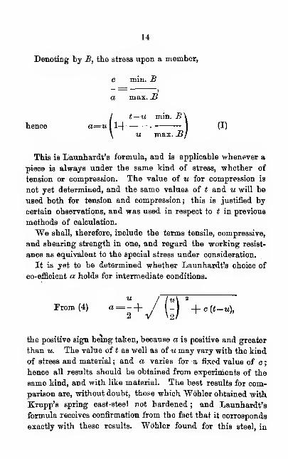
This is Launhardt's formula, and is applicable whenever a
piece is always under the same kind of stress, whether of
tension or compression. The value of u for compression is
not yet determined, and the same values of t and u will be
used both for tension and compression; this is justified by
certain observations, and was used in respect to t in previous
methods of calculation.
We shall, therefore, include the terms tensile, compressive,
and shearing strength in one, and regard the working resist-
ance as equivalent to the special stress under consideration.
It is yet to be determined whether Launhardt's choice of
co-efficient oi holds for intermediate conditions.
2
Prom (4) a= -+ / I -I _|_ c (*-«),
the positive sign being taken, because a is positive and greater
than u. The value of t as well as of u may vary with the kind
of stress and material ; and a varies for -a fixed value of c ;
hence all results should be obtained from experiments of the
same kind, and with like material. The best results for com-
parison are, without doubt, those which Wbhler obtained with
Krupp's spring cast-steel not hardened ; and Launhardt's
formula receives confirmation from the fact that it corresponds
exactly with these results. Wbhler found for this steel, in
15
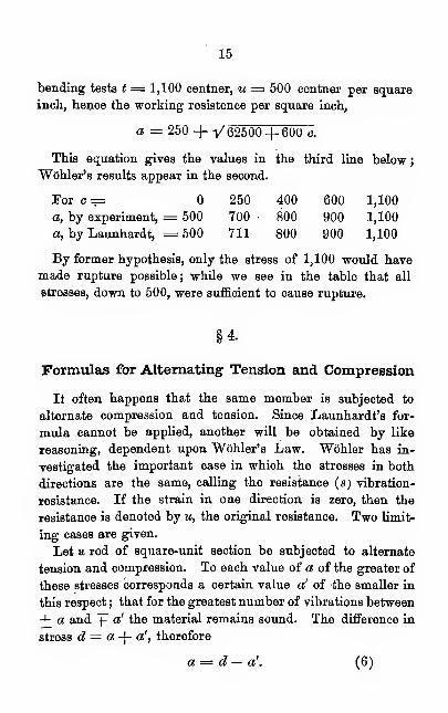
bending tests t = 1,100 centner, u = 500 centner per square
inch, hence the working resistence per square inch,
a = 250 + y 62500+ 600 c.
This equation gives the values in the third line below
;
"Wohler's results appear in the second.
For c ==

16
According' to "Wohler's law, a varies inversely as d. As-
sumea = a d. (7)
But, for a! = o, a = u = d,
for a'= s, a = s = \d.
Uence from (7),
for a = u, a= 1,
for a = s, a = %.
These conditions give the co-efficient
u — s
a=2 u — s — a.
Hence from (6)
u—s u—sa = d— (a-\-a')
t
2m— s—a 2m— s
—
a
I u— s a\and hence a= u (l . —
j
(8)\ m a I
Now, if for a given member in a structure, max. B is the
greatest stress exerted, whether of compression or tension,
and max. B' the greatest in the opposite sense, we have,
a' max. B'
a maxBu—s max. B'
u max. B(II)
and the value of a denotes the working strength.
The original resistance and the working resistance in the
direction of the greatest absolute stress, max B, are denoted by
u and a. As u for compression is not yet known, the value
for tension may be provisionally employed, being somewhat
too small.
17
In some constructions the oscillations between a and a' beginwith a stress equal to zero ; in others, with a stress equal
to c, mostly caused by the dead weight. The operation of
a complete forward and back vibration must be the same,
and cannot be essentially changed by the longer action of c,
which lies far within the limits of elasticity.
Formulas ( I ) and ( II ) serve not only for stresses by
tension and compression, but also for all other kinds, if the
values of t, u and s are known.
If 2> denotes the ratio of the limiting stresses, the least to
the greatest, on a member of a structure, our formulas read
For stress in a determined direction :
«=(l+—*) (la.)
For stress in the opposite direction,
a=w(l-— A (II a.)
§5.
Proof Strength for Tension and Compression.
The old experiments with wrought-iron give more uniform
and higher figures for ultimate strength than the later.
Navier gives the results of seven experiments in France, Eng-
land and Italy ; the mean, per square centimeter, being 3,940,
4,220, 4,290, 4,450, 4,610, 4,680, 5,010 kil.
Under conditions otherwise equal ultimate strength is de-
pendent on the working of the metal. Kirkaldy found for
round and square iron, as a mean of many trials, 4,050 ( va-
riations from 3,780 to 4,330) ; Wbhler, for Borsig and
Komgshutte round iron 4,110 (from 3,730 to 4,530); Knutt
Styffe, soft puddled iron, 3,400 for round iron and 3,460 for
square iron.
18
From 17 trials of English rolled iron at 3 shops, Styffe
obtained 3910, (from 2,940 to 5,100); from 16 with Swedish
rolled iron, at 4 shops, 3,760 (from 3170 to 4,900). Bauschin-
ger obtained for Wasseralfingen rolled iron, 3,890 (from 3,750
to 4,140) ; for angle-iron at the Lothring works of 6 by 6 and7by7cent'r, 3,195. Kirkaldy's mean for angle-iron (manyexperiments) was 3,850 ( from 2,910 to 4,310).
For Borsig rivet-iron, Wcihler found from two trials 5,120;
for English Homogeneous iron, 3 trials, 4,280. A piece fromthe head of an English rail gave to Styffe as average of 3 tests
3,380 ; another piece, with 2 trials, 3,090 ; and a piece fromLow Moor tire-iron 3,760. Bauschinger got for gas pipe per-
pendicular to direction of rolling, 1,400—1,500.
Styffe puts the strength of soft iron for tension at 3,380
;
Gerber and many others assign 3,500 for bridge construction •
Eeuleaux assigns 4,000 ; Von Kaven deduces from Kirkaldy's
experiments for wroughfc-iron the average value, 4,200. Forgood iron, suitable for bridges, the ultimate tension must lie
between 3,500 and 4,000, (see § 12). Eolled figured-iron
generally has little proof-strength and little tenacity; its
use should be avoided as much as possible.
For iron wire suitable for bridge construction, Navier de-duced from the experiments of Buffon, Telford and Seguinthe averages 6,000, 6,360, 6,000; Mosely considered 6,580 aspermissible, Eeuleaux 7,000, Von Kaven ( from Kirkaldy's re-
sults) 6,700 ; Laissle and Schiibler, 5,000 to 8,000 : 6,000 maybe taken as a mean ; but tests are always in order. Theultimate resistance to tension in plate-iron is generally less
than for other sorts, and there is often a marked difference
depending on the direction of stress. The value is generallygreater for longitudinal than for transverse stress. Likerelations appear in the kinds of iron used in bridges ; but asthe stress is generally only longitudinal, the matter is of less
interest.
Kirkaldy obtained from a great number of plates, length-
19
wise, 3,570 (from 3,210 to 3,870), and transversely, 3,250 (from
2,920 to 3,550). On the other hand, Fairbairn, from four
kinds of boiler iron, found 3,540 lengthwise (from 3,080 to
4,060); 3,620 across (from 2,940 to 4,330). From several
boiler plates, Bauschinger obtained from twelve experiments,
longitudinally, 2,820 (from 2,600 to 3,270); transversely, 2,730
(from 2,350 to 3,180). Boiler plate from the exploded loco-
motive " Fugger," gave in undamaged places, lengthwise,
3,040; across, 2,880. Stevens, in America, with the best LowMoor boiler plate, obtained, as a mean of five trials, length-
wise, 4,140 (from 3,890 to 4,500); and with cistern plate, a
a mean of six tests, 2,900 (from 2,320 to 3,670). Bauschinger
obtained from a piece of decided fibrous texture, 2,910 along
the length, 1,910 across. In tests at Gonin & Co., Paris, the
longitudinal strength was greater than the transverse ; but for
charcoal-iron in section only -fa, and for coke-iron \.
From Kirkaldy's experiments, Von Kaven obtains a mean
of 3,800 for plate-iron. The English Admiralty requires for
first quality 3,460 longitudinal, 2,830 transverse ; for second
quality, 3,150 and 2,680 respectively, warm and cold bending
tests being required . Without special experiment the stresses
should not exceed 3,000 longitudinal and 2,700 transverse.
The ratio ? , transverse to longitudinal, agrees well with Kir-
kaldy's mean and with the tests of Edwin Clark.
In the case of steel, the ultimate tensile strength depends
. largely upon the quantity of carbon and other ingredients ; we
shall return to this in another place. As the quantity of car-
bon is not always known, general results only can be given.
Kirkaldy obtained as a mean of 9 different kinds, 6,770, from
4,930 for puddled steel up to 9,340 for cast-steel. Sheffield
Bessemer gave 7,840. Wohler found for cast- axle-steel from
Krupp, Borsig, Vickers and Bochum, an average of 6,250,
with eleven tests ; from 4,020, for Tickers, to 7,670 for Krupp.
Again, for heads of Krupp cast-steel rails, 7,380 ; for Frith
tool steel, 8,400. In the case of hammered Bessemer round
20
steel of from 0.86 to 1.35 per cent, carbon, Styffe found a mean
of 7,730 (from 6,880 to 8,970), with eight testa ; again, from
rolled Bessemer steel, square and round, of 0.38 to 1.39 per
cent, carbon, a mean of 6,480 (4,550 to 9,840), with nine tests
;
and for rolled Swedish round cast-steel of from 0.69 to 1.22
per cent, carbon, a mean of 8,910 (7,280 to 10,170), with four
tests. We may assume for puddled steel 5,000 ; for good me-
dium hard Bessemer steel, 5,500 to 6,500 ; for very good and
hard cast-steel, 8,000. The last value is given by Rouleaux,
Laissle, Schiibler, and others.
For Styrian cast steel plate (Bessemer) Bauschinger found as
the mean of two tests 5,025 longitudinal and 5,180 transverse,
Wdhler, in five tests on Krupp's cast-plate-steel, found an av-
erage of 5,390 long, (from 4,900 to 5,770) and for that of Borsig
5,040 in one test. Tresca obtained 5,400 and 5,760 long, in
two kinds of plate cast-steel ; Stevens, with six tests on best
English Bessemer steel 5,880 (5,240 to 6,090). For plate steel,
longitudinal and transverse, 5,000 may be assured.
For the ultimate resistance to compression we have no
experiments. It is hard to define it in a way practically
sufficient. Bauschinger, in experiments on steel, found that
a complete destruction of the material was hardly to be
accomplished by compression, and he was of opinion with Ron-
delet, that metal yields sooner by bending than by crushing
whenever the depth is more than three times the least trans-
verse dimension (^ 9). Rondelet, and after him Navier, putultimate strength for compression at 4,950, Moseley at 6,580
;
and Bauschinger found the resistance of Bessemer steel con-
siderably greater for compression than for tension. Though in
"Wohler's and Spangenberg's experiments the fracture alwaysfirst occurred on the tension side, it does not necessarily follow
that the metal yields to one strain more than to the other ; andit is safe to assume an equality of working-resistance for ten-
sion and compression. But it is assumed that crushing of thecompressed parts is not to be feared. Fairbairn, in several
21
tests with compound plate-beams, observed that the fracture
began in the upper flange; since that time care has been
taken to stiffen as required, and to provide a rigid bracing at
that point.
§6.
Excess of Elastic Limit.
The limit of elasticity is generally defined as that stress per
square unit beyond which permanent changes of form occur,
while under less stresses the body returns to its former condi-
tion. Eeference is made, not to sudden changes in stress and
shocks, but to gradually increasing strains. But the definition
is theoretically worthless, for a limit so definite is not probable,
and much less is it proven. On the contrary, Hodgkinson
and Clark have observed that there are permanent changes of
form under very small loads. At present we must be content
with defining this limit with Fairbairn, as that stress below
which the changes in form are approximately proportional to
the forces, while above this they increase much more rapidly.
The words " approximately " and " much " are not so indeter-
minate as might be supposed, for, in the experiments of Baus-
chinger, the passage beyond the limit of elasticity could be de-
termined very precisely; as for example in tension ;" for with the
same increase of load a disproportionately great elongation oc-
curred at once, the maximum of which was in every case reached
after some time." This sudden elongation must be credited
to permanent changes of form ; further elongations until near
the breaking limit remain proportional to the stresses, and the
modulus of elasticity is always found to be independent of the
latter. (§9.) In the first definition the changes of form which 1
are permanent from Bauschinger's point of view are neglected.
All experiments, up to the present time, have shown that
when the elastic limit is passed, the tensile resistance is con-

22
siderably increased, while ductility and tenacity diminish; the
metal becoming brittle, and having little power of resistance
to shock. In experiments at the Woolwich Arsenal, an iron
rod, four times ruptured by pull, gave the successive values of
t- 3,520, 3,803, 3,978, 4,186 ; Bauschinger tore apart a piece
of iron seven times, and the resistance increased from 3,200 to
4,400.
Paget found that iron chains after stretching bore a greater
dead weight, but had less resistance to shock. Fairbairn
thought all these phenomena could be explained by the hypo-
thesis that the resistance of all the parts was not at first called
into action, but, like ropes, they became gradually strained in
common under sufficient load. "With this accords the fact that
Bauschinger observed that increase of resistance, especially in
rolled iron, was notably regular when the stress was in the
direction of the fibres. The analogy holds further ; for a rope,
when tense, is more easily broken by shock. And this ex-
plains why a rod under sudden increase of stress breaks
more readily than in case of gradually increasing pull.
When the limit of elasticity is passed, this limit is again
raised. Tresca, in tests of rails, succeeded in pushing the
limit of elasticity to near the limit of rupture, so that it was less
by about one-tenth. The practice hitherto has been to assume
as permissible stress (b) a fraction of the elastic limit. In
this case b increases with the number of loads. But the ma-terial becomes more brittle, and less resistant to shock, and
local passages beyond elastic limits are not excluded. So that
we need not assent to the often-advocated opinion that a tett
of material beyond the elastic limit would be of advantage.
It is worth mention that the increase of resistance with the
passage beyond each limit cannot go on indefinitely ; but a
diminution must occur at some time, unless we assume that
with very gradual increase of stresses and longer intervals,
the original resistance becomes greater than the initial
ultimate strength.
23
Now, if passage beyond the elastic limit can work unfavor- /ably, it should not be permitted. But it is enough to know I
that, according to the numerous experiments of Styffe andothers upon all sorts of iron and steel, the ratio of elastic limit
to ultimate strength generally lies between r}^ and -^-g, and
under the most unfavorable circumstances seldom reaches %.
Wertheim and Styffe have attempted to establish more pre-
cise definitions of the elastic limit, but as they are not better,
either theoretically or practically, than others, it would be
superfluous to consider them. It is since the time of Hodgkin-
son and Clark that an empirical importance has attached
to this limit ; and it is still very narrow in its scope, because
the limit, as above defined, is of no avail in case of sudden
change of strain and of repeated stresses.
Vicat made experiments to determine the effect of lapse of
time upon a dead load. He kept wires loaded up to fths
the tensile resistance, during thirty-three months. Theone with heaviest load broke. Vicat inferred from this,
and because the extension seemed to be proportional to the
time, that every load beyond the elastic limit would, after
lapse of time, cause rupture. Considering that very small
loads cause permanent changes in form, it would be more cor-
rect to infer that any load, if given time enough, will cause
rupture. Fairbairn thought he could prove this by tests on
cast-iron girders. But we do not find that the results of his
experiments warrant his conclusion. But the fact that under
stress beyond the elastic limit the ultimate strength increases,
leads to the conclusion that security against dead-load increases
with time. But if it is objected that a decrease may follow
an increase of ultimate strength, it must be admitted, in
view of all that has been said, that the influence of duration of
dead-load has not been clearly determined. That each load
requires a certain time to cause its correspondent permanent
change has been known since the time of Hodgkinson and
Wertheim, and also accords with Fairbairn's comparison with
&
24
ropes; and, again, it has been observed by Bauschinger.
This also holds true for further changes in form ; and if a rod
stretched again when released, does not at once return to its
previous condition, a so-called secondary action takes place.
This was observed in Kupffer's experiments. Thurston thinks
that in this he has discovered a new phenomenon ; that ulti-
mate strength and elastic limit increase after a strain greater
than the latter, continued for twenty-four hours. But there is
nothing new. in it. That the tensile resistance of iron and
steel is greater under the action of an electric current, and
that the ductility is effected, now one way, now another, by
dipping the metal in acid, seem to be shown by detached
experiments, but this needs confirmation.
§7.
Mechanical Treatment, Heating. Hardening.
Elastic limit and ultimate strength are both increased when
the limit of elasticity is exceeded; ductility and tenacity dimin-
ish. Since under rolling, hammering, and pulling the elastic
limit in the affected places is certainly passed, and perma-
nent changes in form take place, the necessary effect of such
mechanical treatment is obvious.
Heating and slow cooling has an effect exactly opposite to
that caused by passing the elastic limit, for the metal becomes
more ductile and loses in ultimate strength. According to
Tunner, the brittleness produced by mechanical treatment
gradually decreases if the body is allowed to remain at rest.
A wire which broke when bent to an obtuse angle, just after
leaving the plate, increased in pliability within a few days,
and continued to do so during some weeks.
That cold-rolling considerably raises the ultimate strength
was clearly shown by Kirkaldy's experiments, t nearly
doubling in value, passing from 3,220 to 6,260, while anneal-
25
ing reduced it to 3,580. Styffe had an iron rod, which hadbeen previously annealed, hammered cold to half its original
section; the strength was raised from 3,140 to 5,830. Ac-cording to Kick, United States cold-rolled iron is much morebrittle than the common sort. It has often been observed
that the ultimate resistance of cold-rolled metal is diminished
by removal of the skin, the effect of rolling being materially
greater at the surface. These phenomena and many others,
having no apparent relation to one another, are all explained
upon the hypothesis mentioned.
If the mechanical treatment is with heat, both influences
operate, viz. : passage beyond the elastic limit and heating.
These must counter-act, entirely or partially, and the metal maygain in strength, the tenacity remaining constant or increasing.
In England the working of the metal is often repeated.'
A body once annealed is further changed only by higher
heat, unless, meanwhile, it has received some treatment with
opposite effect. It follows, that the effect of annealing must
be greater in the degree that the temperature is higher than
that under the previous mechanical treatment. This was ob-
served by Styffe.
Hardening produces upon steel and wrought iron an effect
like that due to passing the elastic limit, with this qualifica-
tion, that in the case of steel, not only ultimate strength and
elastic limit, but also brittleness are notably increased.
Tempered metal is not suitable for many purposes, because of
its slight power of resistance to shocks. The process oftemper-
ing consists in plunging the red hot metal into some fluid, oil
or water, which suddenly cools it. Brittleness may be some-
what reduced by gradual heating, and may be destroyed by
annealing, together with all other qualities due to hardening.
The effect of hardening is much greater upon steel than on
iron ; and in either case depends upon the chemical constitu-
tion and other conditions.
Tresca, by hardening, raised the ultimate strength of two
26
kinds of plate steel from 5,400 to 8,784, and from 5,764 to
8,880. Wohler cut several bars from a hardened cast-steel
axle and found that the strength of one was 9,209, while that
of the other, which had been annealed, was 7,455. Numerous
tests of the effects of hardening have been published by Kir-
kaldy ; with which those obtained by Styffe agree in the main.
It is shown by experiments made by Wohler, Heusinnger,
"Waldegg and others that metal contracts a little when har-
dened ; Wohler finding that the contraction of a steel-rod of
33 mm. section was about 1 mm. to a meter in length.
With respect to the strength of welds we have the results
of Kirkaldy's experiments. The decrease of ultimate tensile
strength varied between 2.6, and 43.8 per cent. ; while
ductility diminished, especially that of steel. According to
Nasmyth, the strength of welds depends mainly upon the
thorough elimination of the flux employed to hinder oxydation.
Welds should not be used in important bridge-members.
A diminution of strength occurs in cutting screws, amount-
ing, according to Kirkaldy, to from 7 to 30 per cent. The
cause may be that the hard surface of the rod is removed by
cutting ; it may sometimes be due to the cracks made by sharp
dies. This, as well as the hardening caused by the greater
force applied, explains why screws cut by Kirkaldy with blunt
dies held better than those cut with sharp dies. That the
strength of screw-bolts of small diameter proved somewhat
greater, is no cause of wonder ; for Kirkaldy observed that the
strength increased with diminishing diameter, which was to be
expected because of the proportionally greater effect of rolling.
§8.
Influence of Form.
The form of a member may greatly modify its strength.
The bar shown in Fig. 2 has less resistance per square inch
of section than if it were limited by the dotted line. For the
27
load at the right of the dotted line is transmitted only by the
fibres contiguous to the angle to those at the left ; the former,
therefore, receive more than the average stress per square
unit, and fracture will take place sooner at the angle. In
consequence of the bending which, must take place in the case
represented in the figure, the stress is increased ; and the load
would also act unfavorably at the smaller end (§ 18). We can
now understand why Wohler found the strength of bars with
abrupt change of section less than for those with rounded
fillets ; for in the latter case the effect of the load was grad-
ual. In several cases the strength in the first case was
from % to $ as great as in the second, under like conditions;
but these experiments do not give permanent data, since
the change of section and all the modifications mentioned
in the last paragraphs must come under consideration. Ex-
periments by Fietze have proven that the notches at the base
of rails, which are intended to prevent their sliding along the
track, are much more prejudicial than the ordinary theory
supposes. And grooved axles, subjected to torsion, exhibit a
like loss of resistance.
It is remarkable that a rod like Fig. 3, will bear a greater
dead pull than if the whole rod had the smaller diameter or
were grooved through a greater length. The contrary was
to be expected. Vickers found that a rod with a very short
groove bore 12,500 kil. per sq. cr. ; while one turned down a
length of 35 cm. bore only 9,440. In Kirkaldy's experiments
with rolled iron, very short-grooved rods of about 3-4 diam-
eter in length, had an increased tensile resistance of about
l-3d.
These phenomona are hard to explain, but may, perhaps,
be accounted for as follows. Each pulled bar bent under a
heavy load because of the non-homogeniety of the material.
The strain caused by the bending contributed to the break-
ing, but this was less, the shorter the turned portion. If
this explanation is correct, then a very short rod must gen-
28
erally bear more dead pull than a longer of the same mate-
rial and the same section. Whether this is the fact I do not
know. Again, there must be a like difference with compres-
sion, and this has been verified by the observations of Bau-
schinger (§ 9), and others.
Nearly all experiments up to this time, Wbhler's included,
have been made on plain bars. Fairbairn has tested riveted
girders with the special purpose of comparing the values of
different kinds of sections. The girders almost always gav.e
way by the lateral buckling or crippling of the upper flange,
which we now try to prevent by stiff flanges and by bracing
with angle or T iron set at uniform distances. The relation of
the strength of compound pieces to simple members has not
been determined. But it is certain that this ratio greatly de-
pends upon the efficacy of connections, so that more care should
be taken in this respect than heretofore.
§9.
Percentage of Carbon, &o.
What is meant by the terms wrought-iron, steel, and cast-
iron is more easily felt than explained ; a definition, correct
to-day, may not be so to-morrow. The latest authorities say
that wrought-iron should contain about -|, steel from $ to 2,
and cast-iron more than 2 per cent, of carbon. But steel is
to be found with \ and less per cent, carbon, and wrought-
iron with about 1 per cent. Again, it is said that steel, but
not wrought-iron, can be hardened ; but steel with muchphosphorus and little carbon cannot be hardened ; wrought-
iron, and even cast-iron, under certain conditions, may be made
harder.
Greiner, Director of the Bessemer Works at Seraing, and
Phillipart gave this definition of steel as contrasted with
wrought-iron :" By steel is meant that kind of iron which can
be obtained by fluid processes, and which, on account of its

29
consequent homogenity and compactness, is capable of offer-
ing a greater resistance ; and which is also, because of the
method of production, more uniform, both in composition andbehavior." This would exclude many products from the
category of steel.
Benedict's definition of cast-iron, correct in the main, is this :
" By cast-iron is meant that obtained directly from ores, whichdoes not admit of being wrought or welded ; which melts at
a lower temperature, and which contains the greatest propor-
tion of carbon and foreign matter." Either one of the constit-
uents of this definition alone is insufficient ; e. g., wrought-
iron and steel can be got directly from the ore by Siemen's
process.
Chemically pure iron has hitherto been obtained only in
small quantity ; it can be made very soft or very brittle, and
is hard to melt. Iron becomes technically useful by combina-
tion with charcoal. This amounts to from 0.1 to 6 per cent.,
in part chemically combined, in part as graphite. With regard
to the two sorts of metal which receive the names of wrought-
iron and steel, it may be said that in either, the addition of
carbon has an effect upon strength similar to that due to
passing the elastic limit, or to mechanical treatment ; the hard-
ness and ultimate strength increase ; while ductility and power
of resistance to shock and sudden stresses beyond elastic limit
diminish. This is less observable in wrought-iron, because of
the influence of other substances and of the mechanical treat-
ment. But with steel there is a limit, beyond which the ulti-
mate strength, at least for tension and compression, diminishes;
and with this the ductility, so that the properties of the metal
approach those of cast-iron. The position of this limit depends
upon the presence of other elements, and the influences con-
sidered in §§ 6 and 7.
Knutt 'Styffe thought that he had found the maximum ul-
timate tensile resistance of iron and puddled steel at 0.8 per
cent. : of Bessemer and Uchatius steel at 1.2 per cent. The
30
latter agrees with the experiments of Vickers, in Sheffield,
according to which the maximum, is at 1.25 per cent. Karsten
says that steel hardens best, and has most tensile resist-
ance at from 1.0 to 1.5 per centage of carbon. With a greater
percentage the hardness increases, but the resistance be-
comes less ; at 1.75 per cent, all welding quality is lost
;
at 1.8 per cent, it works under the hammer with great
difficulty; at 1.9 per cent, it can be worked no longer;
and at 2 per cent, it has reached the boundaries between steel
and cast-iron ; it cannot be drawn out at red-heat without
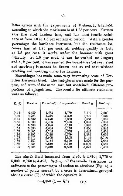
cracking and breaking under the hammer.Bauschinger has made some very interesting tests of Ter-
nitzer Bessemer Steel. The test-pieces were made for the pur-
pose, and were of the same sort, but contained different pro-
portions of spiegeleisen. The results for ultimate resistance
were as follows
:
K,*
31
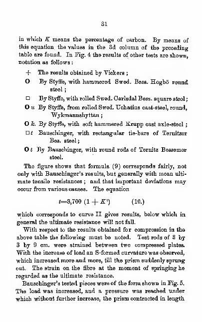
in which K means the percentage of carbon. By means of
this equation the values in the 3d column of the preceding
table are found. In Pig. 4 the results of other tests are shown,notation as follows
:
+ The results obtained by Vickers;
O By Styffe, with hammered Swed. Bess. Hogbo round
steel
;
By Styffe, with rolled Swed. Carlsdal Bess, square steel
;
O u By Styffe, from rolled Swed. Uchatius cast-steel, round,
Wykmannshyttan
;
O 7c. By Styffe, with soft hammered Krupp cast axle-steel;
at Bauschinger, with rectangular tie-bars of Ternitzer
Bes. steel
;
O t By Bauschinger, with round rods of Ternitz Bessemer
steel.
The figure shows that formula (9) corresponds fairly, not
only with Bauschinger's results, but generally with mean ulti-
mate tensile resistances ; and that important deviations mayoccur from various causes. The equation
i=3,700 (1 + X") (10.)
which corresponds to curve II gives results, below which in
general the ultimate resistance will not fall.
With respect to the results obtained for compression in the
above table the following must be noted. Test rods of 3 by
3 by 9 cm. were strained between two compressed plates.
With the increase of load an S-formed curvature was observed,
which increased more and more, till the prism suddenly sprung
out. The strain on the fibre at the moment of springing he
regarded as the ultimate resistance.
Bauschinger's tested pieces were of the form shown in Kg. 5.
The load was increased, and a pressure was reached under
which without further increase, the prism contracted in length

32
to less than half, while the transverse dimensions increased.
The stress per square cm. at this limit, which Bauschinger re-
garded as the ultimate strength, increases with the percentage
of carbon, from 9,250 to 17,800. On the other hand, the elas-
tic limit was independent of the kind of test. Generally very
short steel prisms may be loaded to double the amount per-
mitted for tension.
Phosphorus, like carbon, increases the elastic limit, and ulti-
mate tensile resistance, but diminishes the power of resistance
to blows and to stress differences. It makes iron brittle,
coarsely crystalline, and " cold-short," that is easily broken
under cold working. For this and other reasons it cannot be
used in bridge structures. Phosphorus affects steel still more
unfavorably than iron. According to Greiner, steel, with from
0.2 to 0.25 per cent, of phosphorus, has too little strength for
technical purposes. Phosphor-steel is best suited for rail-
heads, because it resists wear ; but the percentage of carbon
should be diminished to prevent brittleness.
According to Sandberg and Turner, silica has the same
effects as carbon, while Haswell, in the case of steel, with a cer-
tain proportion of phosphorus, ascribes it to a partial neutral-
ization of the bad properties due to the latter. Slag helps phos-
phor iron by diminishing its brittleness ; but it makes it hard
to work without splitting and springing. Next to phosphorus,
sulphur is the moBt undesirable ingredient, having a like effect,
except that it makes the metal particularly apt to break at
red heat. Manganese, too, is a bad ingredient.
The effects of the above mixtures and others upon the
strength of iron and steel are not clearly determined. Con-
cerning their effect in the foundry information can be had from
any text-book upon Metallurgy.
Whether, in a given case, steel or iron is to be preferred,
depends upon considerations of resistance to special strains, of
lightness, security under changes of temperature, economy,
&c. In the application of steel, the proper percentage of carbon
33
is dependent not only on the mechanical working it is to
undergo, but also upon the composition of the ores and the
method of production, because the proportion of other ingre-
dients is determined by these. So Vickers recommends, for
pieces subjected to both tension and shock, 0.62 to 0.75 peif
cent. ; Styffe, for axles of Swedish steel welded, or of one piece,
0.4 to 0.6 ; Greiner, for axles of Bessemer steel from Seraing,
0.3 ; Krupp, for locomotive and marine-engine axles, 0.5 to
0.6 ; for coach axles, 0.6 ; Greiner assigns for Seraing Bessemer
steel, for chains and driving rods, 0.25 to 0.35 ; for tires not
welded and piston-rods, 0.35 to 0.45 ; for steel rails, 0.4
;
for springs, 0.45.
§10.
Influence of Temperature.
The influence of' different temperatures upon the strength of
steel and iron is not satisfactorily explained. With respect to
ultimate resistance only, because of numerous experiments,
has their been a ,growing accord of views . For most kinds of
metal, especially for iron, the ultimate strength appears to in-
crease with the decrease of temperature below zero, but also
tp reach a maximum at a little above 100° C. Within a certain
interval' near 16° the resistance is quite constant ; the begin-
ning and the' rapidity of the increase and the position of the
maximum -are dependent upon the conditions already con-
sidered.
Fairbairn, in tension experiments with bar iron, found, in,
one case, the resistance at 0° equal to, in another, 1 per cent,
higher than at 60". Thurston found in torsion experiments a
decided increase of strength to — 12°. Spence, in experi-
ments in bending cast-iron, found at - 18°, a strength greater
by about 3.5 per cent, than at -f-15°. At higher tempera-
tures, Fairbairn found for bolt iron the maximum of ultimate
tensile strength at 163° 41 per cent, greater than at 1§°
;
34
later experiments with bar iron put the maximum at 213°. Acommission of the Franklin Institute, at Philadelphia, found
the maximum strength 15 per cent, greater than its ordinary
value at about 288°. Styffe has published the results of
numerous experiments. See his Table VII.
Beyond the maximum the ultimate resistance decreases at first
slowly, but very rapidly at red-heat. In this respect, too,
the, different kinds of metal behave very differently, and the
diminution may possibly be the quicker and more rapid the
lower the temperature of the metal when under mechanical
treatment. Tensile resistance Fairbaim found to diminish from
202°, where it was about the same as at ordinary temperature,
a low red heat, by about 17 per cent. ; up to ordinary red heat,
by about H4 per cent. Experiments at the Franklin Insti-
tute found the ultimate tensile resistance, at 575° lowered by
0.66, and at 700° by 0.33 from the ordinary value. Bau-
schiDger observed the strength of puddled plate, transverse to
the direction of rolling, to be at red heat 780 kil. (2,700 ordin-
ary), and of rolled iron along the fibres, 750 (4,430 ordinary).
These results are of importance with respect to constructions
exposed to fire. Kirchweiger, of Hanover, regards the diminu-
tion of tensile strength by heating as the cause of boiler ex-
plosions ; attempting to prove at the same time that a boiler
filled with water may become red-hot. Bauschinger thinks it
possible that the continual variations and differences of tem-
perature of the outer and inner surfaces may diminish the co-
hesion of the laminse of the plate ; the inner laminse bearing a
disproportionate share of the strain, and the shearing resist-
ance being lessened.
A frequent theme of discussion is the influence of cold upon
resistance to sudden changes of stress,—shocks in particular.
It cannot be denied that more axles and wheels break in win-
ter than in summer. Styffe maintains that rupture is often
due to the fact that the parts are held fast, and, therefore, can-
not yield to the contracting influence of the cold : again, for
35
tires, axles and rails, the effect of shocks is increased by the
diminished elasticity of the ground.
Sandberg, in an appendix to the English translation of
Styffe's work, maintains that these are not the principal causes
of breaking. He laid iron rails upon granite supports which
lay upon granite rocks, so that the elasticity of the foundations
might be the same in any season. The two halves of these
rails were tested by blows with a 380 kil. ball at — 12° in
winter, and + 29° in summer ; and it was found that at
— 12° the rail could withstand only ^ of what it could at 4-
29°. This showed, at least, that there are some kinds of iron
that are weakened by frost. Styffe had tested only under
dead loads, and in this respect his results were trustworthy.
Sandberg also found this peculiar result: that Aberdare
rails, which bore in summer 20 per cent, more strain than
those from Oreusot, in winter had 30 per cent, less strength.
This could be explained on the hypothesis of a difference in
constitution which affected the strength unequally. Fairbairn
had already shown the unfavorable effect of phosphorus and
sulphur at low temperature ; and Sandberg thought it possible
that different results would have been reached had the metal
been free from phosphorus.
Unfortunately the chemical constitution of the rails was not
determined ; but it seems likely, that phosphorus, which always
diminishes resistance to shock, may operate more actively at a
low temperature. Its effect also increases under high heat.
Styffe found that the grain of a screw-bolt of phosphor-iron
was so affected, that a single blow of the hammer broke it.
Steel, with increasing mixture of phosphorus, loses its capacity
to undergo repeated heating without losing its peculiar prop-
erties.
In the year 1871, Joule, Fairbairn, Spence and Brockbank
contributed to the Manchester Literary and Scientific Society
four papers upon the influence of cold upon iron and steel.
All agreed that resistance to dead load was not diminished by
36
cold, but considerably increased. Brockbank held it certain
that cold diminishes resistance to shock; this, Joule and
Fairbairn did not admit. All referred to experiments. Noone will question the exactness of Joule's tests ; but the test-
pieces were wires, needles and nails, so that the results may not
hold for larger pieces ; while Fairbairn and Spence tested only
under dead load. A series of observations by Brockbank con-
firm the results obtained, by Sandberg. Hails were tested with
blows ; and in frosty weather they had far less strength than
at ordinary temperature : a hollow cast-iron core-rod, about
which a cylinder had been cast, cooled down to — 1\°, broke
square and smooth, leaving a brittle-looking surface, while the
pieces were made stiff, and sound again by heating. A rod
of roundViron of best quality, of 38 mm. diameter, which lay
a week exposed to frost and was covered with ice, broke at
4£° under a single blow of a hammer .weighing 5.4 kil.
All authorities admit the increase of resistance to tension
tinder great cold, though they deny that there is a diminution
of power to resist shocks. This is bad reasoning. It is certain
that resistance to dead load is somewhat increased by frost
;
and besides this, according to Styffe, the elastic limit;just as
is the case under hammering, rolling, hardening, &c; but as
'with all the latter, resistance to shock increases, there seems
to be no reason for a contrary judgment in the first case.
Styffe has proved that iron becomes stiffer with decrease of
temperature; agreeing with Sandberg.
Thurston concludes from results of his experiments that
phosphorus and other substances, inducing cold brittleness,
may impair resistance to shock at low temperatures, which
seldom occur ; and that in other cases resistance to dead
load, as well as to' shock, is increased Iby cold. This
would be novel, but it must first be proven. Thurston's test-
machine is well adapted to the lecture-room, being convenient
and cheap ; but it is not suitable for scientific experiments re-
quiring results numerically exact. The velocity, an important
37
element, is not regulated; the methods of measurement aremuch too primitive to answer to small differences due to tem-perature
; and it is not to be taken for granted that torsion-tests
are best suited to determine the properties of resistance offibrous and laminated metals.
In a report of the Massachusetts Eailroad Commissioners
(1874), mentioned by Thurston, it is said, that "cold does not
make iron and steel brittle and unsuitable for mechanical pur-
poses, and that it is not the invariable rule that the most break-
ings occur on the coldest days." The membership of the Com-mission is not given, nor is it certain what kinds of metal wereunder consideration. Did it contain a large percentage of
phosphorus ? Were the rails iron or steel ? It has been found
in Northern climates—Canada, Sweden, and Bussia—that a
low steel, with £ to \ per cent, phosphorus, was affected by cold
much less than iron. According to Styffe, there is no authentic
case in which good steel contained more than 0.04 per cent, of
phosphorus ; though in one English iron rail there was 0.25
percent., and in Dudley iron 0.35.
We draw the following conclusions from all the data at hand
:
(a.) Iron and steel, which are entirely or nearly free from
all foreign materials, have neither their resistance to dead load
notably increased by cold, nor their resistance to shock di-
minished, (b.) Certain elements, not exactly determined, but
phosphorus certainly, very much diminish resistance to shock
and sadden change of stress, (c.) The question cannot be
definitely settled until the chemical constitution is determined.
(d.) Statistics of results in warm and cold latitudes, in summerand winter, after long frost, on days of sudden intensity of
cold, are required.
The above has reference to the immediate influence of tem-
perature. In regard to the effect of repeated changes of tem-
perature, Wohler conjectures that frequent vibrations of mole-
cules caused by heat, have the same effect in destroying
cohesion as vibrations caused by external forces. Data from
38
observation have not been obtained. Spangenberg, after ex-
amination ofthe fracture surfaces, did not adopt this hypothesis.
Bauschinger, after testing boiler-iron, thought it possible that
the strength of the plate was weakened by long action of the
fire. But this decides nothing as to the effect of repeated
influences. If Wohler's hypothesis is correct, we should recog-
nize, in change of temperature a cause of destruction, not only
of metals, but also of all other solid bodies. And safety co-
efficients would be of no avail, for if we should make one
beam twice as large as another, each half of the first would be
as much affected as the whole of the second. In any case,
bridges and buildings, which are subjected to only slight
variations in temperature, will certainly be more likely to fail
from other causes.
§11.
Bauschinger found the ultimate bending strength of steel
;
i. e., the greatest fibre-tension at the instant of rupture, as given
by the ordinary theory, always greater than the absolute tensile
resistance, (see table in § 9). Wohler obtained a like result
for wrought iron and steel; but the original strength was not
less for bending than for pull. The experiments of Bauschin-
ger and Styffe show that the modulus of elasticity for bending
may be assumed as equal to that for tension, without great
error. All these results show that the common theory of bend-
ing gives results accurate enough for practice. Of especial
interest in this respect are Bauschinger's tests, in which the
length of the gravity axis or elastic line remained unaltered bybending, and the original plane transverse sections remained
perpendicular to it, even under very strong bending stresses.
Though it is not asserted that the method of calculation for
very thin-walled plate-girders is exact in every respect;yet it
is as sound as that for trusses, in which hinges are supposed,
but rivets used ; and it is safer than the ordinary method for
compound trusses.

39
The modulus of elasticity of steel per sq. centimeter, is, ac-
cording to
Bending tests by Kupffer, 2,124,990 (cast and file steel).
Pull and bending tests by Styffe, 2,412,300 (Bessemer steel).
Bes. steel pre-
pared for
test.
Tension tests by Bauschinger, 2,215,500,
Compression tests by " 2,i,91,000,
Bending tests by " 2,110,000,
Crushing tests by "2,082,500, (Bes. round rod).
Tension tests by " 2,310,000, (Bes. tires).
Bauschinger found the elastic modulus for torsion and
shearing to be 862,000. From these results it follows that for
steel we may assume as average
For tension, compression and crushing E, =2,150,000.
2
For shearing and torsion E'= - E= 860,000.
5
In experiments with English tire iron, bar iron and Swedish
wrought iron, Kupffer gets a mean of 2,053,070 ; Styffe gives
for good iron, with very little phosphorus, 2,171,100; but for
iron containing much phosphorus and slag, 1,930,600. The
following figures are established for iron :
For tension, compression and crushing, E= 2,000,000.
2
For shearing and torsion, E'= -E= 800,000.
5
No effect of carbon upon the elastic modulus could be observ-
ed ; but with Styffe and Kupffer, it seemed to increase a little
with the specific gravity and with lowering of temperature.
Passing the elastic limit, and working in the cold condition,
were found by Tresca and Stvffe to cause a decrease.

4U
According to Kupffer, hardening of hard steel decreases the
elastic modulus by about 6.5 per cent. ; but on the other hand
Morin ascribes to cast steel a possible increase of E by harden-
ing, by 50 per cent. By Wertheim's theory and Kirkaldy's
tests, the specific gravity is somewhat diminished, if the metal
is worked cold or in any way the elastic limit is passed, while
the volume does not decrease, as has often been assumed. Yet
all these influences are not so great and well determined that
they require or permit a general review.
In calculations, the specific gravity of wrought iron may be
put at 7.6 to 7.7, that of steel 7.8.
§12.
The Examination of Metals.
The higher the limit of elasticity, the greater the strain
which a body will bear without permanent change of form.
Eaise this by hammering or hardening, and the body will be
restored after greater strains; hence the extended use of springs.
If the ordinary elastic limit served for all kinds of load, and if
we were sure that it would never be exceeded, then it would
be desirable to set the limit as high as possible for any con-
struction. But the. ordinary value is not sufficient in case of
shock. In our riveted bridges,for example, local excesses mayoccur, because of unequally distributed strains. These are less
dangerous, if the material is strong enough beyond this limit,
so that a gradual change of form takes place, as in the case of
a uniformly distributed force over the whole section.
The more extensible and tenacious the metal, the less risk
in exceeding the elastic limit. It is well known that a very
ductile and tough metal best resists shocks and sudden changes
in stress. We should, therefore, judge of the fitness of metal,
not only by the height of the elastic limit and the ultimate
resistance, but also by its ductility and tenacity. The greater
41
the latter qualities tlie greater the elongation before rup-
ture.
When a rod is broken by a pull, there is a contraction of
section at the breaking-point, beginning a little before rupture;
attended by a decided elongation, which is independent of that
which always occurs when the elastic limit is exceeded, and
is approximately proportional to the length of the rod. Asthe total elongation at rupture is in part proportional
to the length of the rod, in part independent of it, the ratio
A— of the total elongation to the length of the rod, can deter-
l
mine the ductility only in the case of rods of equal length ; for
the shorter the rod, the greater relatively the share of elonga-
tion at the point of rupture.
Kirkaldy, who has had the advantage of very, many tests in
this regard, recommends that we measure the excellence of
the metal, both by its ultimate tensile resistance and by its
contraction at the point of rupture. The stress at the break-
ing point, per square unit of the contracted part, increases
with both the tension and the contraction ; and the stress ac
this time furnishes the best means of determining the resist-
ance. The results so obtained, arranged in oraer, give a trust-
worthy scale of values ; but, if the gradation were according
to ultimate strength only, very ordinary kinds might stand
high in the scale. Kirkaldy found that the ultimate strength
of coarse, crystalline metal, was equal to that of very tough
and dense sorts.
The mechanical treatment and the method of production
have their influence. So plate-iron is generally ofless ultimate
strength and ductility than round-iron.
The Department of Public Works, in India, has published
the following table of requirements for estimate and supply,
based on Kirkaldy's results. Contraction is expressed in per
cent, of the original cross section.
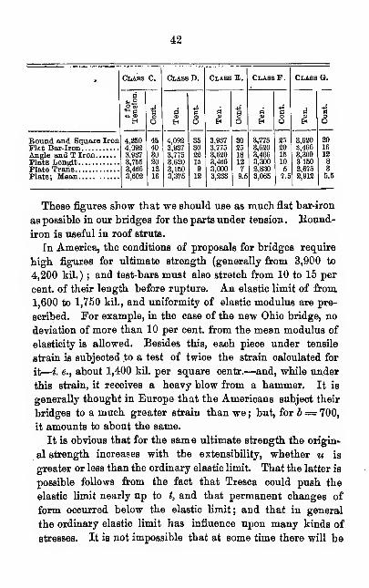
42
•
43
found a sufficiently determinate relation between original
strength and ultimate strength and contraction ; or, between
the ultimate strength and strain per square unit of the
rupture-surface ; or generally between u and values under
dead load ; so that u can be at least approximately found
for each metal, and the numerical values be substituted in
Launhardt's formula. And the vibration-strength s could
be derived from some relation, or might be estimated.
s
Wohler found the rates — nearly the same in metals so
uunlike as Phoenix iron and Krupp's cast-steel; the values
being respectively -fa and j%. It would be desirable to make
a great number of tests by bending, shock, &c, of metals for
which the values of t, u, and s, have been fixed by numerous
experiments. We should then have a better guide for the
tests required of the manufacturers.
§ 13.
Permissible Strain.
The values of the stresses having been calculated, the work-
ing strength a gives the stress per square unit, which can be
maintained without rupture, under any number of repetitions.
No reference is made to influences that do not admit of sys-
tematic investigation, such as shocks due to the passing of
wagons in the streets, flaws, rust, &c.
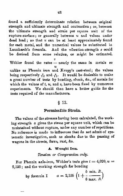
A. Wrought Iron.
Tension or Compression only.
For Phoenix axle-iron, Wohler's tests give t = 4,020, u =2,195 ; and the working strength for bending
(5 min. B..
1 -|)
6 max. B.i
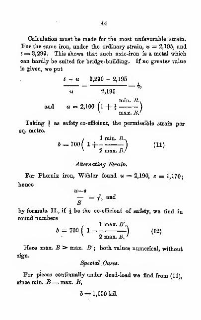
44
Calculation must be made for the most unfavorable strain.
For the same iron, under the ordinary strain, u = 2,195, and
t= 3,290. This shows that such axle-iron is a metal which
can hardly be suited for bridge-building. If no greater value
is given, we put
t - u 3,290 - 2,195= —=i,
u 2,195
(min, i?..
1 + i I
max. B.'
Taking \ as safety co-efficient, the permissible strain per
sq. metre.
(1 min. 2?.,
H )(ii)
2 max. B.I
Alternating Strain.
For Phoenix iron, Wohler found u — 2,190, s = 1,170
;
henceu—s— = T
7B and
8by formula II., if J be the co-efficient of safety, we find in
round numbers
(1 max. .G'..
1) (12)
2 max. B. '
Here max. B > max. B' ; both values numerical, without
sign.
Special . Gases.
For pieces continually under dead-load we find from (11),
since min. B= max. JB,
b= 1,050 kil.
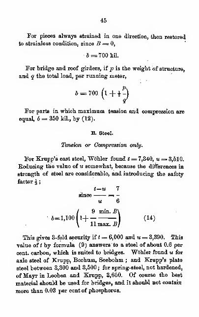
45
For pieces always strained in one direction, then restored
to strainless condition, since B= 0,
• 5 = 700 kiL
For bridge and roof girders, if p is the weight of structure,
and q the total load, per running meter,
700. ('+0
For parts in which maximum, tension and compression are
equal, b = 350 kil., by (12).
B. Steel.
Tension or Compression only.
For Krupp's cast steel, "Wohler found t= 7,340, u = 3,510.
Reducing the value of u somewhat, because the differences in
strength of steel are considerable, and introducing the safety
factor £
;
t—u 7
since = -u 6
(9 min. B\1+
)(14)
11 max. B]
This gives 3-fold security if t = 6,000 and u= 3,390. This
value of t by formula (9) answers to a steel of about 0.6 per
cent, carbon, which is suited to bridges. Wohler found u for
axle steel of Krupp, Bochum, Seebohm ; and Krupp's plate
steel between 3,300 and 3,500 ; for spring-steel, not hardened,
of Mayr in Leoben and Krupp, 3,650. Of course the best
material should be used for bridges, and it should not contain
more than 0.03 per cent of phosphorus.
46
Alternating Strains.
For the same cast axle-steel, Wohler found s= 2,050
;
if u = 3,510, say 3,300, and safety factor is ^ ;
u — s 5
since = —u 12
/ 5 max. B'\
6=1,100 (1
I (15)
\ 11 max. B J
This gives 3-fold safety for u = 3,300, below which value
the original strength of steel did not fall in Wohler's experi-
ments, and for s= 1,800, while in Krupp, Boreig and Bochumaxle-steel the vibration-strength was about 2,000.
Special Cases.
For permanent strain under constant load (14) 6=2,000kil. , For parts always strained in the same direction, then
restored, b = 1,100 (14) and (15). For bridge and roof
girders, and generally for pieces for which
Pmin. B -=- max. B =-
f 9 *\6=1,1001 1-|
J
V 11 qj
For parts under equal max. tension and compression 6 =600 kil., (15).
O. Remarks.
The safety factors, and permissible strains for steel andiron, have special reference to bridges and large' structures.
Hitherto the permissible strain for wrought-iron has been set
47
at 700. But it is found that 6, for wrought-iron, may vary
between 350 and 1,050. The most favorable case is that of
dead load, the most unfavorable that of alternating tension
and compression. In this we see how varyable are the figures
required for the safety of the different parts of a structure.
Hitherto much material has been wasted in building. It is of
no avail to the general security of a structure to employ 700 in
places where from 700 to 1,050 may be required, and then to
employ 700 in a place where 350 is ample. If there is only
one diagonal or vertical in a bridge, which suffers nearly equal
strains of compression and tension, the security is only half as
great as has been assumed up to the time of Wbhler's investi-
gations. It would certainly be wise to strengthen such excep-
tionally weak points, and so strengthen the entire structure.
The above values of b, for wrought-iron, give 3-fold security
if «= 3,150, u= 2,100, s= 1,050. "Wohler puts 1,100 for
permanent structures, in case of alternation of strained anct
strainless conditions, under tension only, or compression only
;
and 580 for equal tension and compression ; the previous figures
being 700 and 350. These correspond to a safety factor of &.
For temporary structures, the values of u and s are greater
than we have assumed in (3). For the present this will
answer, by taking all values as given above, and selecting
another safety factor, say \ under favorable conditions.
We have not derived the value of b from Wohler's tests of
Krupp's spring steel, because the values of u, s, and t are not
all determined, and because the steel had properties which
can be assumed only in exceptional cases. Softer and more
extensible metal will always be used for bridges. If with this,
the ultimate resistance diminishes, it does not follow that it
does so in the same ratio as the original strength ; for this
depends also on the ductility. In the case of hardenedMlspriDg-steel, with diminishing t, - = : for steel not
t 2.50
48
1 11hardened, ; for cast axle-steel, ; and for iron, to
2.20 2.03 1.83
1
. Hence estimate of working strength depends upon1.5
this. For Krupp's spring-steel, Wbhler's bending tests give
a=3,650( 1-f
for the same hardened,
/ 6 min B\1+ j
\ 5 max. BJ
(3 min. B .
1-| )
2 max. B'
If very low steel is used for a bridge, the permissible strain
must be less. For example, if only 0.45 per cent, carbon is
desired, and a minimum ultimate strength of about 5,200 kil.
is prescribed, (14) and (15) may be changed to
(3 min. B<1-j ) (14a)
4 max. B'
(1 max. B' .
1) (15 a)
2 max. B '
These formulas, for t = 5,200, u = 3,000, s = 1,500 give
three-fold security.
For the arch-bridge at the Champ de Mars, of Bessemer'
steel, the permissible stress for all parts, whether under tension
or compression, was put at 1,000 kil. There are smaller cast-
steel bridges in Holland and one of puddled-steel in Sweden.
The most important is the bridge at St. Louis, over the Missis-
sippi, which has a middle span of 158.5 m., and two end spans
of 152.4 m. The advantages of steel are its greater security
against intense cold and its lightness. The difference in ex-
49
pense will not long stand in the way, as the cost of steel is
diminishing.
§14.
Calculation of Dimensions.
max. BThe formula F= is employed in the new calcula-
6
tion of dimensions which differs only in the choice of b. In the
following reference is to tension and compression only.
A. Trusses.
For wrought iron ; (a) stress in one direction; (6 ) alternat-
ing compression and tension
—
(1 min. B .
1_| .) (11)2max.£'
(1 max. B' .
1)
(12)
2 max. B '
In the second formula max. 3 is the greater and max. B
'
the less of both max. strains of different signs. The numeri-
cal values are substituted without sign. For girders with uni-
form load,
/1 P\
6=700(1+--) (13)
p being the weight of girder and q the total load per unit of
length. For steel employ (13) (14) (15).
Example.—To find permissible strains and sections for all
parts of the half-truss, Fig. 6. Calculations by Hitter's meth-
od, which is especially fitted in application of the new estimate
of dimensions, because both limiting values of stress are easily
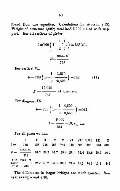
50
found from one equation, (Calculations for rivets in § 19).
"Weight of structure 1,000; total load 6,000 kil. at each sup-
port. For all sections of girder
/1 1
\6=700 ( 1+-"-. ) =758 kil;V 9. fi /2 6
max. BF=
758
For vertical VI.
. 1 1,875 ,
b= 700(1+-. )=742 (11)v 2 15,625 '
15,625
F = = 21.1, sq. cm.742
For diagonal IX.
, 1 4,600 .
6=700(1 )=531.v 2 9,550 I
9,550F= =18, sq. cm.
531
For all parts we find
I II III IV V VI VII VIII IX Xb= 758 758 758 758 743 743 688 688 531 531
max. B.F= 31.7 39.3 37.7 39.8 31.1 23.4 15.8 18.0 13.7
758
Old max. B.value 33.9 40.7 38.8 30.3 31.4 31.1 14.9 13.1 9.3of F. 700
The differences in larger bridges are much greater. Seenext example and § 30.
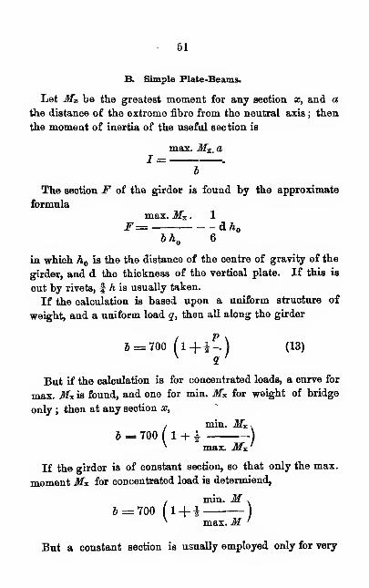
51
B. Simple Plate-Beams.
Let M.v be the greatest moment for any section as, and a
the distance of the extreme fibre from the neutral axis ; then
the moment of inertia of the useful section is
max. M-x. a1 = .
b
The section F of the girder is found by the approximate
formulamax. M*. . 1
F= &hbh 6
in which h is the the distance of the centre of gravity of the
girder, and d the thickness of the vertical plate. If this is
cut by rivets, f h is usually taken.
If the calculation is based upon a uniform structure of
weight, and a uniform load q, then all along the girder
b = 700 (l+i--) (13 )
But if the calculation is for concentrated loads, a curve for
max. Mx is found, and one for min. M* for weight of bridge
only ; then at any section x,
(min. ffl*.
1 + I )
max. Jfx '
If the girder is of constant section, so that only the max.
moment M* for concentrated load is determiend,
(min. M .
1+i)
max.M '
But a constant section is usually employed only for very
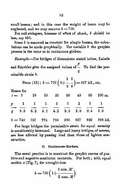
52
small beams ; and in this case the weight of beam may be
neglected, and we may assume b = 700.
For rail-stringers, because of effect of shock, b should be
less, say 650.
Since b is assumed as constant for simple beams, the calcu-
lations can be made graphically. For variable b the graphic
process is the same as in continuous, girders.
Example.—For bridges of dimensions stated below, Laissle
Pand Schiibler give the assigned values of -. To find the per*
1missible strain b.
I1 1
\From (13) ; b = 700 ( 14-- . - }= 817 kil., etc.v 2 3'
Hence for
1=1 10 15 20 30 40 60 100 m.pllllllllq 8.3 6.2 4.7 4.2 3.5 3.0 2.4 1.9
6 = 742 757 774 783 800 817 846 884 kil.
For large bridges the permissible strain for equal security
is considerably increased. Large and heavy bridges, of course,
are less affected by passing load than those of lighter con-
struction.
O. Continuous Girders.
The usual practice is to construct the graphic curves of pos-
itive and negative maximum moments. For both ; with equal
section x (Fig. 7), for wrought-iron
1 1 min. M
'
.
6 = 700(1-1 ).
^ 2 max. M'
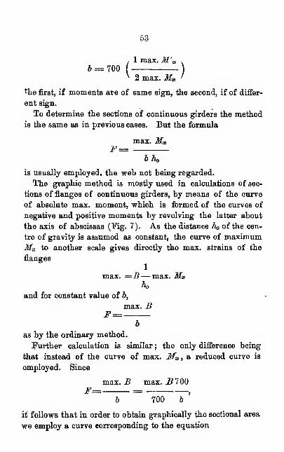
53
1 max. M'u700
N 2 max. Mx '
*he first, if moments are of same sign, the second, if of differ-
ent sign.
To determine the sections of continuous girders the method
is the same as in previous cases. But the formula
max. MxF:
b h
is usually employed, the web not being regarded.
The graphic method is mostly used in calculations of sec-
tions of flanges of continuous girders, by means of the curve
of absolute max. moment, which is formed of the curves of
negative and positive moments by revolving the latter about
the axis of abscissas (Kg. 7). As the distance h of the cen-
tre of gravity is assumed as constant, the curve of maximumMg> to another scale gives directly the max. strains of the
flanges
1
max. =.B— max. Mxh
and for constant value of b,
max. BF=
b
as by the ordinary method.
Further calculation is similar ; the only difference being
that instead of the curve of max. Mx , a reduced curve is
employed. Since
max. B max. _B 700F= =
,
6 700 6
it follows that in order to obtain graphically the sectional area
we employ a curve corresponding to the equation
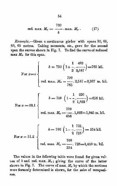
54
720red. max. Ma = max. Mx
b(17)
Example.—Given a continuous girder with spans 52, 65,
65, 62 metres. Taking moments, etc., gave for the second
span the curves shown in Fig. 7. To find the curve of reduced
max Mx for this span.
For x=o >
, 1 482,5 = 750 ( 1+ -. ) =765 Ml.
v 2 2,587 I
700red. max. Mx = .2,587=2,367 m. til.
765
For a; =33.1 *
1 230= 700 (l--. ) =656 kil.
v 2 1,823 I
700red. max. Mx= . 1,823=1,945 m. kil.
656
For x =51.2 ->
I1 721
\,= 700 ( 1--. ) = 354kil.V 9 798 /2 728'
700red. max. Ma = . 728=1,440 m. kil.
354
The values in the following table were found for given val-
ues of 6 and red. max. Mx ;giving the curve of the latter
shown in Fig. 7. The curve of max. Ma by which the sections
were formerly determined is shown, for the sake of compari-
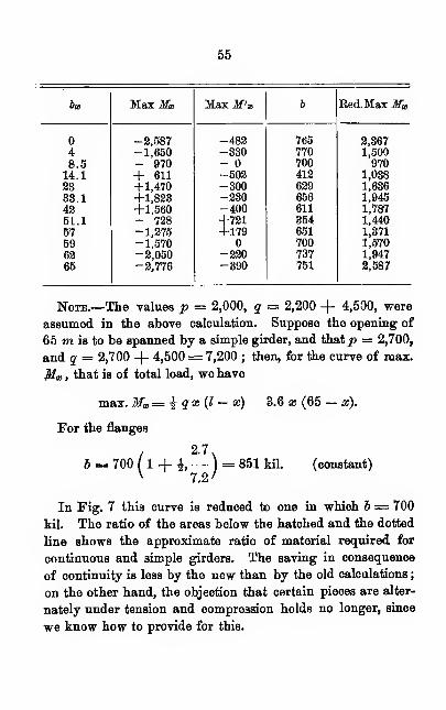
55
bx
SHEARING RESISTANCE. RIVETING.
That the stability and duration of iron structures depend
upon carefully arranged connections needs no proof, yet the
calculation and distribution of riveting is generally according
to pattern. That harm has not oftener come from this is due
to the fact that, after hot-riveting, the contraction of the rivet
shank caused by cooling produces a great amount of friction
between the riveted parts.
This friction generally amounts to from 800 to 1,600 kil. per
sq. cm. of rivet section, and depends on the length of the shank,
and at first alone takes up the greater part of the stress
on the joint. But, at the moment of rupture, before which
there is a slipping of the plates and a deformation of the
rivet-heads, friction is not to be depended on; besides, it
may disappear as a consequence of shocks, so that all the
stress comes on the rivets. Hence friction is left out of
account, and dependence is put on shearing resistance alone.
What is to be understood by shearing resistance ? Hither-
to the name has been given to that shearing strain along a
unit surface, which is just sufficient to cause separation. But
this is only the resistance to a single dead-load ; while, accord-
ing to Wohler's law, less strains, repeatedly applied, may pro-
duce separation. One feels that this must be true. If weattempt to break the connection in Kg. 8, by shearing off the
bolt with the hand, we first try a single pull P ; if this is not
enough, we pull again and again, and possibly succeed by re-
peated efforts. Hence the greatest shearing resistance is
against dead-load, is at the mean for alternation of strain
and strainless condition, and is least when there are alternat-
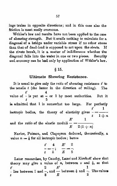
57
ings trains in opposite directions ; and in this case also the
friction is most easily overcome.
"Wohler's law and results have not been applied to the case
of shearing strength. But it avails nothing to calculate for a
diagonal of a bridge under variable stress if no other stress
than that of dead-load is supposed to act upon the rivets. If
the rivets break, it is a matter of indifference whether the
diagonal falls into the water in one or two pieces. Security
and economy can be had only by application of Wohler's law.
§15.
Ultimate Shearing Resistance.
It is usual to give only the ratio of shearing resistance t' to
the tensile t (the latter in the direction of rolling). The
t' 4value of - is put at - or 1 by most authorities. But it
t 5
is admitted that 1 is somewhat too large. For perfectly
t' 1
isotropic bodies, the theory of elasticity gives - =t 14-n
E' 1
and the ratio of the elastic moduli — = .
E 2 (1 -j- n)
Navier, Poisson, and Clapeyron deduced, theoretically, a
value n = \ for all isotropic bodies ; hence
t' 4 E' 2
t b' E b
Later researches, by Oauchy, Lame and Kirchoff show that
theory may give a value of n, between o and i, so that
t' 2 E' 1
- lies between 1 and - , and — between £ and -. The values
t BE 3
58
must be settled by experiment. The experiments of Kirchoff,
Wertheim, Eegnault and others, made to determine n, are
of less value in respect to ordinary dimensions than for those
examined. They gave n between \ and \ for steel and
t' 4 3 E'iron, so that - may be taken between - and - , — between
t 5 4 E2 3- and -.
5 8
f 4 E'_ 2Wohler, under certain hypothesis, finds - = - and — — -
t 5 E 5
when the shearing edges do not lie in the same plane (Fig. 1).
t' 350With tests of bars torn and sheared by dead-load - = for
t 445
550 4Phoenix axle-iron ; for Krupp's cast-steel plate : - exactly
738 5
fin first case ; nearly that in the second. For torsion - was
t
E' 1.95
only a little less, and — =. Bauschinger obtained the
E 5
same value exactly in a series of experiments on Bessemer steel
(See § 11). The common theory that torsion is a kind of
shearing, Spangenberg concludes to be true, because of the
appearance of fracture surfaces ; and until further investiga-
tion is made the same figures may be taken for torsion as for
shearing. The experiments also confirm the relation between
tension and shearing which is deduced from the theory of
elasticity. That caution must be used in applying these
results to anisotropic material is clearly shown by late experi-
ments by Bauschinger. Besistance to shearing was of very
different values, depending on the angle between its plane and

59
that of the direction of rolling. Bauschinger gives six different
dispositions (Fig. 9). Of these I, III, IV, are of practical
import. In I, III, IV, t' was but little smaller than t for ten-
sion in the direction of rolling ; in II the difference was con-
1
siderably greater ; in V and VI the average was t' — - t,
2
and the value sank to ^. The differences were greater in
proportion to the degree of fibrous and laminated condition.
Rolled-iron from Wasseralfingen, for an initial value t =3,893, gave t', I 3,448, II 2,836, III 3,590, IV 3,060, V 1,787,
VI 1,767. For two kinds of Lothringer angle-iron, for t =f 4
3,160, t' = I 2,630, III 3,030, IV 2,620 ; or - greater than -.
t 5
For several German, French and English boiler plates, for t=3,180, these were the results; I 2,410, III 2,460, IV 2,540;
mean about $ of 3,180. For Styrian cast-steel plate for locomo-
tive boilers t' I 3,920, III 4,380, IV 4,460 ; for t= 5,025;
4i. e., t' : t greater than - •
It may be said in general, that in the practical cases I, III,
t' 4IV, - - is the best ratio.
t 5
It may happen, especially with boiler-plate, that for III and
IV, t = t' or t < t' ; but this must not be taken for granted.
§ 16.
Permissible Shearing Stress.
It follows, from "Wohler's tests, in which the shearing
edges lay in different planes (Fig. 1), and Bauschinger's,
t'
in which they lay close, that the ratio - depends on this
t

60
difference in some way not understood. "Wohler found that
the shearing and torsion strength for repeated alternating
strains could be assumed as Jths of the ultimate tensile
strength in the direction of rolling, under like conditions
(i. e., equal ratios of limiting stresses), as was to be inferred
from theoretic considerations. This relation, then, may be
assumed as holding in practical cases, (I, III, IV). Then t',
u', s' and a', are found by multiplying each corresponding
4value by-.
5
For stress in one direction
(t' — u' > min. B1 )
m' ' ax B4i , t — u min. B . 4
=-u(l-\ )=-« (III)
5 ^ u max. B ' 5
This applies to the riveting of those members which are
always under tension or always compressed ; for the sections
of plate girders near supports, and for riveting of boilers.
For stresses in opposite directions
(u'—s\ max. B'1 ) (IV)
max. B4 , u—sm&x.B'. 4
= - u ll j =-a.5
'
u max. .B' 5
This applies wherever there is alternate pull and thrust.
A. Wrought-Iron.
For strain in one direction
4 / 1 min. B \
J' = -J==560 ll-\ ) (18)5 v 2 max. B'
61
and for opposing stresses
4 .1 max. B\ft' = -6 = 560(1
) (19)5 v 2 max. B >
For torsions the ratios are to be got from the limiting
torsion moments; then (18) and (19) give the permissible
strain in the outermost fibers. For dead-load, ft' = 840 ; for
cases of stress and restoration alternating, ft' = 560 ; for equal
opposing stresses, b' = 280.
B. Steel.
For one direction
4 , 9 mia. B,6' = - ft = 880
5
For opposing stresses
4 ,5 max. B\V = - b = 880 (1
)5 v llmax.£'
For dead-load ft' = 1,600 ; for alternate stress and restora-
tion ft' = 880 ; for equal opposite stresses ft' — 480.
C. Remarks.
Possibly in cases of shearing and torsion acting in opposite
directions the above may seem to be anomalous ; but Wbhler's
experiments confirm the results. For Krupp's cast axle-steel
u = 3,510, s = 2,050, and u' = 2,780, s' 1,610; and by direct
and indirect process, (u' — s' max. B'\1
)u' max. B I
i 9 mia. B.(1+ -)v 11 max. B>
(max. B\1 _ 0.42 )
max. B'
62
u — s max. _B' \iI
u — s max. xs \
a'=-u 1
5 \ u max. B I
= 2,808 / 1 - 0,
max. B\42
max. 5
'
If steel, as low as that supposed in (14a) and (,15a), then
4 ,3 min. B .
&'= - 6=800 ( 1 +)
(20a)
5:
4 max. B f
4 / 1 max. 5',
;- 6=800 (15 v 2 max. 5
1)
(21a)
If the stress for II, Fig. 9, is to be found, we may put b'=i b;
while for V and VI, which are not of practical import, b'
should not be more than £ b.
§17.
Web of Plate-Girders.
The ordinary calculations do not give sufficient values for
the thickness of the vertical web of plate-girders (Pig. 41).
Experiments have proved that the plate is most easily de-
stroyed by lateral buckling ; but the forces involved cannot
be analyzed. To prevent this the girder is stiffened, and
the web should not be too thin. It is to be considered
that the plate may be weakened by corrosion, and that the
pressure on the rivets may be too great. The effects of other
strains must be considered . The horizontal tension and com-
pression are proportional to the distance from the axis of
gravity, and is therefore less at any other place than at the
outermost fibre, and less than the permissible value. The
63
horizontal shearing resistance for vertical unit across thebreadth, called specific, is greatest at the axis, viz.
:
max. VxB„= ;
h
h being the distance from the centre of tension and compres-
sion. In order to resist the horizontal shearing at any dis-
tance from the axis, a plate is required of thickness d, found
by the formula,
4 max. V1 d. - b =
5 h*
5 max. T^,j
d=4 hb
This will also answer for vertical shearing ; the vertical and
horizontal stresses being equal at all points : making h =-i%ths h„ ; h being the distance between centres of flanges ; wehave
d= Hmax. V.
bh
Oblique strains may be greater than the vertical and hori-
zontal, if the vertical shearing Vx and the moment Mx have
high values at the same time, as at the posts of continuous
bridges and in small girders under concentrated loads. But
only the oblique tensions and compressions are of higher value,
the highest being at the junction with the flange. In un-
favorable cases in which regard is had to oblique stress, take
-^ths of max. Vx for simple girders, fths for continuous
;
3 max. Vm& = -. (22)
2 bh
64
5 max. Vg,
d=-. (23)3 bh
These are the formulas of Laissle and Schubler.
The values of b for wrought-iron in the respective eases
when the shearing is always in the same direction, as near
supports ; and when it acts in opposite directions, as near the
middle of spans, are
—
1 min. Vx .
6=700(1+-)
\ 2 max. Vx '
(1 max. Vx v
1--)
2 max. Vx
Formulas (22) and (23) give the maximum value only of
max. Va; this always occurs at a support, so that only the first
b
formula for b is employed.
For a simple plate-girder with uniformly distributed load,
max. Vx= iq I ; min. Vx = \pl; hence
J=700( 1+— )V 2 2
/
and by substitution in (22)
930+ 1+- W,
2?'
in which p = weight of girder, q= total load in met. kil.
per meter ; I= width of span in metres ; h = distance be-
tween centres of gravity in centimeters.
Example.—For simple plate girders of I = 7 and 10 m.
65
of span ; h = 70 and 100 ctr.; p = 900, q= 8,100
; p=1,100, q = 6,600 kil.
What thickness of web answers for all forces ?
8,100.7
ForZ= 7 d = =0.82 cm.1
930 (1-1— )70v 18'
6,600.10
For 1= 10 d= = 0.66 cm.
930 ( 1+ - ) 100V 12/
For long girders d may be increased to 0.9 or 1.
§18.
Method of Riveting.
"Whether rivet holes should be drilled or punched is a ques-
tion upon which opinion is divided. Tvro points are to beconsidered: (1) the probability of good riveting; (2) the
resistance of good riveting. For the first, drilling is the
better.
The strength of riveting depends on the resistance of the
plate and on the strength of the rivets. The strain upon the
middle portion of Fig. 10 must be transmitted by the fibres at
the circumference of the rivet-hole ; these must, therefore
receive more than the average stress.
The chief advocate of punching is Fairbairn; his mainargument, that it tests the quality of the metal. He repeat-
edly says that bad iron will tear with punching, and would berejected, and that this is decisive. It is true that the worst
iron would tear visibly ; but it does not follow that other kinds
would not be injured. The following table of the average of
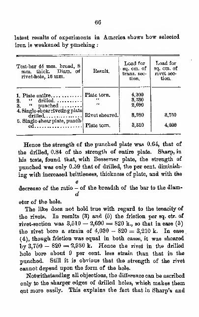
66
latest results of experiments in America shows how selected
iron is weakened by punching :
Test-bar 44 mm. broad, 8
mm. thick. Diam. of
rivet-hole,, 16 mm.
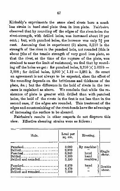
67
Kirkaldy's experiments the same sized rivets bore a muchless strain in hard steel plate than in iron plate. Fairbairn
observed that by rounding off the edges of the rivet-holes the
rivet-strength, with drilled holes, was increased about 12 per
cent. ; but, with punched holes, the increase was only 2| per
cent. Assuming that in experiment (5) above, 3,210 is the
strength of the rivet in the punched hole, not rounded (this is
about fths of the tensile strength of very good iron plate, so
that the rivet, at the time of the rupture of the plate, was
strained to near the limit of resistance), we find that by round-
ing off the holes we get : for punched holes, 3,210 X 1-0275 =3,298 ; for drilled holes, 2,930 X 1-12 = 3,281 k. So exact
an agreement is not always to be expected, since the effect of
the rounding depends on the brittleness and thickness of the
plate, &c. ; but the difference in the hold of rivets in the two
cases is explained as above. We conclude that while the re-
sistance of plate is greater with drilled than with punched
holes, the hold of the rivets in the first is not less than in the
second case, if the edges are rounded. This treatment of the
edges and countersinking of the rivet-heads havethe advantage
of increasing the surface to be sheared.
Fairbaim's results in other respects do not disprove this
view. Effective shearing strains were as follows :
Hole.
PunchedDrilledPunchedDrilledDrilled and rounded
PunchedDrilled
Drilled and rounded
Load persq. cm.
3,0802,9203,2403,2003,190
6,9706,1707,250
Riveting.
By machine
handhandmachine
hand
Singleshear.
Doubleshear.
68
Fairbairn's inference of greater strength for punched holes
was due to the fact that he did not take into account the decid-
ed difference in the diminution of resistance of drilled and
punched plates ; this not regarded, judgment must be in favor
of punching.
In general, then, drilling is to be preferred to punching
;
but there may be modifying circumstances which make punch-
ing preferable. In this case the punched parts must be at least
" hand-warm''. All parts that are at all torn must be rejected
;
bad-fitting holes should be carefully reamed down ; the parts
near the holes must be heated, this being important whenthe metal is brittle, and indispensable for steel. Sharp found
that the strength of punched steel-plate, 0.8 cm. thick was
raised from 3,300 to 5,200 kil. ; that of drilled plate without
heating, was 5,600. The difference 400 may have been loss
of ultimate strength caused by heating. Kirkaldy found that
by hardening, the strength of punched plates was increased
more than by heating ; but it must be remembered that this
diminishes the resistance to impact.
Seven experiments by Fairbairn gave a mean of 7? per cent,
greater strength for hand than for machine riveting. ThisFairbairn attributes to the fact that when riveting is done byhand the rivet is hardened by being hammered while cool. Hefavors machine riveting in other respects, because the holes
are more surely plugged, and the rivets hardly ever work loose.
Hot riveting is better than cold, because a greater frictional re-
sistance ensues, and because the closer joints keep out corrosion.
If the total thickness of plate is more than 10 cm., it is better
not to employ hot riveting, because the contraction might sheara rivet or spring up its head. For shank-lengths of morethan 15 cm., heat should not be used. But in this case cold
riveting will hardly answer, and turned screw-bolts of slight
taper, say! J , may be used. Gerber says that such bolts
have from 6 to 8 per cent, more resistance than hot-riveting,
because of the more complete filling of the holes.
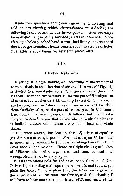
69
Aside from questions about machine or hand riveting and
cold or hot riveting, which circumstances must decide ; the
following is the result of our investigation. Best riveting
:
holes drilled ; edges partly rounded ; rivets countersunk. Goodriveting : holes punched hand-warm ; bad fitting ones broached
down ; edges rounded ; heads countersunk ; heated near holes.
The latter is superfluous for very thin plates only.
§19.
Slastic Relations.
Riveting is single, double, &c, according to the number of
rows of rivets in the direction of strain. If a rod S (Fig. 11)
is riveted to a non-elastic body K, by several rows, the row Imust still bear the entire strain B, for the part ofB assigned to
//must act by tension on I II, tending to stretch it. This can-
not happen, because I does not yield on account of the defi-
cient elasticity of K, so the part of B assigned to Ilia trans-
ferred back to I by compression. It follows that if an elastic
body is fastened to one that is non-elastic, multiple riveting
is inefficient, since the outermost row must bear the whole
strain.
If K were elastic, but less so than S, being of equal or
greater cross-section, a part of B would act upon II, but only
so much as is required by the possible elongation of I II. Imust bear all the residue. Hence multiple riveting of bodies
of different elasticities, e. g., steel and iron, or cast and
wrought-iron, is not to the purpose.
But like relations hold for bodies of equal elastic modulus.
In Pig. 12, if the diagonal represents the rod 8, and the flange-
plate the body,K; it is plain that the latter must give in
the direction of B less than the former, and the riveting I
will have to bear more than one-fourth of B, and each of the
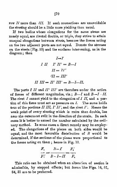
no
row II more than III. If such connections are unavoidable
the riveting should be a little more yielding than usual.
If two bodies whose elongations for the same stress are
nearly equal, are riveted double, or triple, they strive to attain
unequal elongations between rivets, because the forces acting
on the two adjacent parts are not equal. Denote the stresses
on the rivets (Fig. 13) and the surfaces intervening, as in the
diagram; then
1=1'
i ii rw = b—i11= II'
ai = nrII 111= II' III' = B—I—II.
The parts I II and II' III' are therefore under the action
of forces of different magnitudes, viz. ; B—I and B-—I—II.
The rivet I cannot yield to the elongation of J II, and a por-
tion of this force must act as pressure on /. The same holds
true of the portions II III, I' II', and the rivet I'. Hence the
weak point of every riveting which is more than double, lies
near the outermost rviit in the direction of the strain. In such
cases it is better to exceed the number calculated by the ordi-
nary method. In some cases a direct remedy may be employ-
ed. The elongations of the pieces on both sides would be
equal, and the most favorable distribution of B would be
determined, if the sections of the pieces were proportional to
the forces acting on them ; hence in Fig. 13.
Fl B-I FJ
Fl B- I-II Ft
This ratio can be obtained when an alteration of section is
admissible, by stepped offsets ; but forms like Figs. 14, 31,
34, 35 are to be preferred.
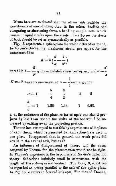
71
If two bars are so riveted that the stress acts outside the
gravity-axis of one of them, then in the other, besides the
elongating or shortening force, a bending couple acts whichcauses unequal strains upon the rivets. In all cases the rivets
of both should be set as symmetrically as possible.
Fig. 15 represents a splice-plate for which Schwedler found,
by Navier's theory, the maximum strain per sq. cr. for the
outermost fibre
• 4 3 .
* = */—-)\a or
'
B e'
in which b = — is the calculated stress per sq. cr., and a= —F e
3K would have its maximum at a = - and, e. g., for
ff=l
2
5 3
4 2
K— = 1 1.28 1.33 1 0.68.
6
i. e., the resistance of the plate, so far as upon one side it pro-
jects by less than double the width of the bar would be in-
creased by cutting away the projecting portion.
Theune has attempted to test this by experiments with plates
of caoutchouc, which represented bar and splice-plate cast in
one piece. It appeared that in general the weak point did
not lie in the neutral axis, but at 0.
An inference of disagreement of theory and the cause
assigned by Theune for the phenomenon would not be right.
In Theune's experiments, the hypothesis of Navier's deflection
theory—deflections infinitely small in comparison with the
length of the rod—was not verified. The force, B, could not
be regarded as acting parallel to the axis of the splice-plate.
In Pig. 16, S refers to Schwedler's case, T to that of Theune,
72
for caoutchouc. To obtain the latter from the former requires
a new deflection, in which the outside fibre of the splice-plate is
partially freed from strain, and the weak point is moved
toward the section 0, which is now strained in the same way
as the sections over the posts of continuous girders.
We perceive, by referring to the above values for K : b,
that hardly a perceptible increase of stress upon the splice-plate
can come from the projecting portion, and that, cutting away
the latter would generally cause a better distribution of strain
upon the rivets.
§20.
Total Section and Number of Rivets.
A riveting is called single-shear, double-shear, . . . i - shear,
if under the strain there occur one, two, three, or i changes
of the direction of force (Figs. 17 to 22), for according as the
force, B, must shear the rivet in one, two, or more, in order to
destroy the junction, the whole, a half, &c, of B operates in
shearing off one section. Each «-shear riveting can be regarded
as divided into i single-shear, as is shown by the dotted lines in
Figs. 19, 20. The plate thickness of each single-shear will
hereafter be denoted by 6.
Next we have to determine the total section Fn of the
rivets required by a connection of rods or entire plates. Let
max. _B be the greatest shearing force upon this system ; then
we have, if b denotes the unit stress for tension and compres-
sion, and b' the permissible shearing stress per sq. ctr.
max. B max. B 4for single-shear Fn= = = -F (24)
V ib 5
max. _B max. B 5
for i-shear Fn= = =— . F (25)ib' %ib 4 i
in which .Fis the total useful section of the rod.
73
The necessary number n of rivets is easily found. If
1
c?=diam. Fn = n . - it cP.
4
hence for single shear,
d max. B 5 max. B 5
w, = . = . F (26)
it d2 V n d2 b n d2
for i-shear
4 max. B 5 max. 5 5 nx
ind? b' ind? b ind? i
The values of 6 or b' are not necessary in this calculation
if F is correctly determined.
That double-shear riveting is twice as effective as single maybe seen in Fairbairn's results, referred to in § 18.' The ratio
in that case is still more favorable for double-shear riveting.
This is because the cutting effect of edges is more certain and
effective in single-shear riveting. Straight-shear rivetings
have this advantage : they do not produce a couple tending to
bend the plate and spring the rivet-heads. When it is diffi-
cult to set a sufficient number of single-shear rivets, a forked
arrangement, like that in Pig. 24, may be employed, making
the riveting double-shear, and of half the number.
The larger the rivets the fewer required, and the further
apart they may be set. But it is to be observed that with the
strain upon a rivet the corresponding strain upon the wall of
the rivet hole increases so that a destruction of the rivet hole
may ensue. Although in many cases a little burring is not
objectionable, yet we must infer from Gerber's experiments
that the rivet-wall should not be strained more than twice the
permissible tensile strain per square cr. of its projection, hence
nd? 4. - b = or < dd . 26 or d < or= 3 . 28
4 5
74
remains. This holds both for a single and an i-shear and riv-
eting, and, in the latter case, S denotes the thickness of plate
of each resolved riveting.
The value of d generally lies between l$d and 3c?. A fixed
ratio d-+- S as prescribed for general use will not answer in
bridge construction where the use of more than two or
three sizes of rivets is not convenient.
Remarks.
It has been shown that the strain on a rivet is compounded
of a shear across and a tension along due to cooling : and that
no certain method of calculating the values is known. But if
the strain lengthwise preponderates, then the friction-resist-
ance of from 800 to 1,600 k. will not permit a shear : and if
the friction is removed by any cause there is no further lon-
gitudinal stress. More unfavorable stresses are not to be
expected in the intermediate conditions, since with the ordi-
nary shearing values the tension lengthwise has diminshed
considerably at the beginning of shearing.
The initial strain lengthwise is not exactly determinable,
since we do not know the co-efficient/1
of friction. Assuming
it as -£th, and recollecting that R, the friction, acts on two
sides, we get as value of longitudinal strain per square ctr.
of rivet section,
BZ= — =1,200 to 2,400 kil.
2/
This would be a large value for the best fine-grained iron
for dead-load, if its ultimate resistance were increased bypassing the elastic limit (§6). As L increases with the length
of the shank what has been said about heating in § 18
applies.
We have assumed Fn = f F in accordance with all the re-
sults of theory and experiment hitherto obtained ; any deviation
15
from this must have sufficient ground. Reasons formakingFu=f F are that rivet iron is better than common rolled iron, andthat the bars lose some of their strength by drilling or punch-
ing. On the other hand the reasons for making F„= % F are
the unfavorable effects of oblique strains and the insufficient
distribution of strain among the rivets in plates that yield but
little, on account of multiple riveting or unsymmetric group-
ing. These effects cannot be decisively balanced ; hence there
is no ground for changing the ratio Fn = £ F.
Faiample.^-The number of rivets necessary for the fasten-
ing of diagonals and verticals of the truss (Fig. 6) is to be
found, d = 2.5 cm. Riveting single-shear.
5
By (26) n = . F= 0.25 FncP
For the vertical VI, F = 21.1,
hence n= 0.25 X 21.1 = 6.
For the other pieces we have
II III IV V VI VII VIII IX X2?= 31.7 39.2 27.7 29.8 21.1 22.4 15.8 18.0 12.7
w=8 10 7 8 6 6 4 54For the riveting of the vertex-plates with the flange, see the
example in § 25.
§21.
Indirect Transmission of Force.
It has been assumed that the bars to be riveted are in close
contact. Otherwise the relations are entirely different ; but
to this case no attention has hitherto been given.
Suppose that bar / is to be riveted to bar III, Fig. 25, so as
to transfer the force, B, from I to HI. Suppose bar II lies
between J and III, for the present supposed not to be
76
weaker than I. The force, B, can pass directly from / only
to II, and nL rivets are required at A. But, if H is not
to be strained, it must be freed from an equal strain, B, be-
fore A, at D, for which wt rivets are required. The indirect
transmission, with an intervening plate, therefore, requires
twice as many rivets as the direct.
That the force, B, can actually pass directly only from /to II
is shown by a glance at Fig. 26 ; for, in order that the strain
may be transmitted to a bar, the rivet must be pressed in the
direction of the force against the wall of the rivet-hole in the
bar. And the same figures shows how II and III is discharged
to HI, and that, theoretically, the rivets may be limited by the
dotted line. If the bar were compressed, the walls of the rivet-
holes would act on the opposite side against the rivets.
If there are two intervening plates, the transmission takes
place as in Fig. 27, and 3 n^ rivets are necessary. And, gen-
erally, for any single-shear riveting, indirect transmission with
m intervening plates, requires m -\- 1 times as many rivets as
direct transmission. Hence from (26) for m intervening
plates
5(m+l)max. B 5(m+l)»=(m+l)n l
= = F (28)ntf b it d3
in which F is the useful section of the rod, whose strain, max.
B, is to be transmitted. In this equation (26) is applied for
the value m= o.
The principle and formula (28) serve for any one of the
single-shear rivetings, into which an i-shear riveting is resolved.
In Fig. 28, e. g., to transmit B from I to III, 2 \ nx= 'In*
rivets are required. More than two-shear rivetings are not
employed for indirect transmission.
It was assumed above that the intervening plates were not
weaker than those whose strain they had to transmit. This
limitation is not necessary, and our results hold true in gen-
77
eral. For example, if, in Fig. 29, the intervening plate II
were weaker than i, it would have been necessary to regard
the force transmitted as there indicated, if II is at least half
as strong as J. Hence, giving the rivet-number for direct
transmission the same index as the force
n = 2 njr-\-2 (ni —ni^)=2 nj
exactly as above required.
Filling-plates, sometimes unavoidable (Fig. 30), need only
single riveting. Either they move freely with the rivets,
without offering resistance, so that transmission from / to
II occurs at A; or they are so disposed that the strain
passes from the filling-plate at D to the plate intended to
receive it. But it is to be noted, that in the first case
the rivets bear a strong bending stress ; for which provision
can be made by additional rivets. (Applications in §§ 24
—
27).
22.
Riveting of Ears.
The previous formulas serve to determine the number of
rivets of a given diameter for any fastening. The arrange-
ment remains to be considered. In § 19 we found that the
rivets should be arranged symmetrically with reference to the
axis of each rod ; that single riveting is best if the bodies are
of equal or different elasticity, and yield in different degrees in
the direction of the force ; that in all cases more than double
riveting brings an unequal strain upon the outermost rivets,
and that when possible, the rivets in the outer rows should be
set as close as possible.
In riveting bars in the webs of trusses, the piece should
be weakened by rivet-holes as little as possible. In the
distribution of the rivets of a diagonal, as in Fig. 31, a single
78
hole must count for weakening, and the useful working section
becomesF= bj, S= (b — d ) 8. For though a breadth of
row II less by d serves to transmit the force, still the latter is
diminished by the amount taken up by I. If the useful
breadth b1 , in the outermost row answers for the whole piece,
then for II, III, &c, the following values are sufficient:
B-
1
II+III+ . . .
bn= ibi = bi
B b
B-I-II III+IV+ . . .
bin= hi= bj
B Bin which I, II, &c, signify the strains taken up by the respec-
tive rows. If D are wanting in a row, then only (6
—
8—D) 8
would be the useful working section. Hence the number in
in two successive rows never increase by more than the num-
ber required in the outermost row. After that the only con-
dition is
ltd? 4 2'd 8 b < or = . - b or 8 < or= - d.
4 5 3
If d = Id, then in row I there should be more rivets than
the increase in two successive rows. But such thick pieces
are seldom used ; and it must not be forgotten that 8 always
denotes the thickness for one-shear riveting.
Since for-7F, in Pig. 31, less breadth is required than for
III, though less weakening is caused by rivet holes, the section
may be diminished in another way. In § 19 it was shown
that such a diminution is desirable in order for a uniform dis-
tribution of strains on the rivets ; so that the ends of the bars
are often of the forms shown in Figs. 14, 31.
In pieces under compression account need not generally
be taken of the diminution of sectional area by riveting,
since the transmission of the strain occurs along the whole
79
breadth (Figs. 32, 33). Hence it is not of so much conse-
quence that as few rivets as possible should be set in row I
;
but it is well to rebate, say one-half of the rivet holes, as tend-
ing to weaken ; because exact contact of hole and rivet is not
to be expected at all points.
In order to effect a distribution of strain as uniform as possi-
ble at the rivetings, the rivets of each row are set opposite the
intervals of the adjacent rows, generally opposite the middle
(Figs. 31, 40, 42), each rivet then receives the stress of a
strip of breadth determined by the equation
nd? 4.-b = 0db
4 5
it d.-./? = -- d (29)
5 6
The stress upon each strip must be transferred to the rivet,
hence within each group through each cross section there must
run as many strips of breadth /3 as the number of rivets remain-
ing, provided, of course, that no more rivets are set than
required theoretically by 26 and 27. Hence, for the purpose
of symmetric and direct transfer, a strip may be oarried through
in two halves each •£ fi wide, up to its rivet. This grouping
(Figs. 34, 35, 39, 40) was first employed by Schwedler. Wehave now to determine what breadth the strip must have be-
hind the rivet. The useful sectional area of the bar can sel-
dom be an exact multiple of /3, but is somewhat less, because
for each fraction of the calculated number of rivets a rivet is
counted, and sometimes extra ones are added.
The permissible minimum distance e between rivets in the
direction of the strain, and the minimum distance r of the last
row'from the edge, depend upon the condition that the same se-
curity is required against shearing of the rivets as against the
forcing out of the hatched pieces; Fig. 36. For this, calculation
ia made for the surfaces undw shear between the tangents to
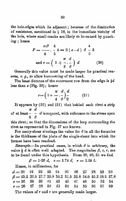
80
the hole.edges which lie adjacent ; because of the diminution
of resistance, mentioned in § 18, in the immediate vicinity of
the hole, where small cracks are likely to be caused by punch-
ing ; hence
ndP 4 4P = . - b=2{e-d) S - b
4 5 5
/ n d .
and e = I 1 -f - . - ) d (30)V 8 6 '
Generally this value must be made larger for practical rea-
sons, e. g., to allow hammering of the head.
The least distance of the outermost row from the edge is id
less than e (Fig. 36) ; hence
, n dsdr-(l+ — .-)- (31)
v 4 6*2
It appears by (30) and (31) that behind each rivet a strip
n dof at least - - d is requred, with reference to the stress upon
8 S
this rivet ; so that the dimensions of the loop surrounding the
rivet as represented in Fig. 37 are known.
For many-shear rivetings the value for 8 in all the formulas
is the thickness of the plate of the single-shear into which the
former have been resolved.
Example.—In practical cases, in which S is arbitrary, the
value \ d is often well adapted. The magnitudes /?, e, r, are
to be found under this hypothesis. From 29, 30, 31 we find
/? = 1-26 d, e= 1.79 d, r = 1.29 d.
Hence, in millimetres, for
d =20 21 22 23 24 25 26 27 28 29 30
/S=25.2 26.5 27.7 29.0 30.2 31.5 32.8 34.0 35.3 36 5 37.8
e= 36 38 39 41 43 45 47 48 50 52 54
r= 26 27 28 30 31 32 34 35 36 37 39
The values of r and e are generally made larger.

81
§23.
Riveting of Entire Plates.
The grouping of rivets is determined in advance, being uni-
formly arranged in one or two rows. If the two plates are of
like material and the same strength, double riveting is gener-
ally preferable ; the necessary number of rivets remains the
same, and the strain acts uniformly ; but the useful section Fis larger and the strength at the seam is less reduced by the
rivet-holes. Conditions that make a very tight joint desirable
may prevent double riveting.
The necessary number is not usually found by the formulas
of § 20 ; but depends on the rivet-pitch ; this depends upon
the condition that there should be the same security against
shearing the rivet as against tearing the plate. Hence, for
single or double riveting (Figs. 38, 40), since the rivets are
always single-shear,
tccP 4.-b = (D-d) Sb
4 5
n cF 42 .- b = {D-d) Sb
4 5
and for single riveting D = ( 1 H . - I d (32)v 5 S /
, 2 n d .
for double riveting D = ( \-\ ) d (33)v 5 S>
Higher then double is not admissible, because of unequal trans-
mission of strain.
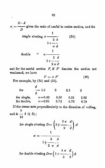
82
D-d- gives the ratio of useful to entire section, and for
D1
single riveting a (34)5 d
1+n d
double5 6
1+2nd
and for the useful section F, if F' denotes the section not
weakened, we have
F = a F' (36)
For example, by (34) and (35).
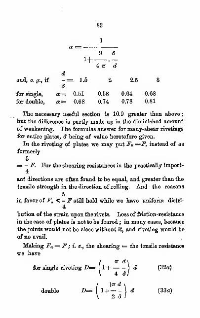
83
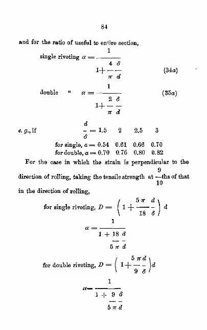
84
and for the ratio of useful to entire section,
1
single riveting a = .
4 8l-\ (34a)
n d
1
double " a = (35a)2 8
n d
de. g., if - = 1.5 2 2.5 3
8
for single, a = 0.54 0.61 0.66 0.70
for double, a =0.70 0.76 0.80 0.82
For the case in which the strain is perpendicular to the
9direction of rolling, taking the tensile strength at —ths of that
10
in the direction of rolling,
f5 it d1 -)
18 6
1
a =1+ J8 8
5 n d
5 ltd
9 8
1
/ 5 nd \
for double riveting, D = l-\ )dV 9 rf/
1+98bn d
85
dThen for — = 1.5 2 2.5 3
dfor single, a = 0.57 0.64 0.69 0.72
for double, a = 0.72 0.78 0.81 0.84
Formulas (32a) and (35a ) were used by Grashof and others.
§ 24.
Eivet-Pitch in Plate Girders.
A special treatment is necessary for plate girders. The dis-
tance between rivets in any row is to be determined. Connec-
tion with the vertical plate is effected exclusively by row I(Fig. 41). Without this the plate would slide freely between
the two angle-irons ; the row /must resist the greatest strain
upon 7 caused by such sliding. Denoting the horizontal
shearing force per unit of length upon I by &# and the per-
missible strain on a rivet by N, there are required for a unit
max. JEtr
of length, n = rivets. If in a single row, the distance
N1 N
between rivets is e2= - = (37)
n max. B^
The rivets of the row I are double-shear, hence
jrtf'4
N=2 b.
4 5
But this value is permissible only when the pressure upon the
rivet-hole is not too great, which is always the case ( § 20 )
when d 5» 3.25.
86
1
Since 6 — - d, d > 3.28 ; and if the pressure on the rivet-
2hole is not too great we may put
b
N=d&2b,ao that by (37) e7= 2d dmax. ^j
in which d is the thickness of the plate and the exact value of
max. Hx is to be substituted.
As a hair-splitting calculation would be superfluous, we mayproceed as follows : The horizontal shearing per unit of length
Vzis greatest in the neutral section ; its value is H = — ; in
h
which Vx is the total vertical shear in the section x, and h, the
distance between the centres of tension and compression. Fromthe neutral section to I, the horizontal shearing force diminishes
but little ; this may be provided for, if we put for h the larger
value h„ viz., the distance between the centres of gravity of the
flanges; at I, -Sj=— , approximately. The decrease is less, the
Kthinner the vertical plate and the thicker the flanges ; and with
absence of vertical plate the equation is perfectly accurate.
We have for J, «/
b
= 2dd h„— .
max. VzFormula (38) holds for constant as well as variable 6. We
assume the latter, and for wrought iron, according as in Vz,
at x is always of the same or of alternating sign, as in (§ 17).
, min. Vx .
5 = 700 (l + i)^ max. Vx '
. max. Vx\6 = 700 (1 -i )
^ max. Vx'
87
If et varies with it is clear that in all practical casesmax. Va
this quotient, and therefore eT, is the smallest at a support,
both for simple and continuous girders. If er is to be constant
for the whole length, the calculation should be made only for
a support, and the first value of b is employed. Howevergreat the variation of eIt by the old method of calculation, it
is not so by the new, for towards the middle not only max. Va ,
but also b diminishes. A constant value of er is desirable for
small girders ; for large, it may be made a little more at the
middle of spans.
If a simple plate-beam is uniformly loaded, then, at sup-
ports, p being dead-load and q total load per unit of length.
Max. Fa, = i q I; min. Vx = i p I.
P\6 = 700 (l +i-)
and by substitution in (38) we obtain for the greatest permis-
sible distance between rivets at the supports.
p1+—2q
e = 2,800 d h (38a)
ql
d and h being in centimeters.
(38) and (39) show that the pitch is proportional to the
thickness of the vertical plate and the distance between the
centres of flanges, which indicates how to increase the pitch
if desired.
For II, Fig. (41), it is of import to know the number of
horizontal plates. With more than one there is indirect trans-
mission of force ; since the strain is always taken up by the
last plate imposed. If m is the number of plates imposed,
88
max. Ha ihe greatest horizontal shearing strain at II at the
section x
max. Hnn^m ,
Nand for r rows,
r r Ne„= -= • (39)
n max. HnmGenerally r= 2, and the rivets at II are one shear, and the
condition d = or < 3, 2d is always fulfilled, S being the
thickness of the horizontal angle-leg
;
ltd* 4then iV= b,
4 5
Ixd* b
and c/7 :
5 »z max. -Hj/
The ratio of the horizontal shearing force at II to that at J
is as the section of all the horizontal plates to the section of the
entire flange; i. e., if y denote this ratio;
rxHn=y Sj=y—
K2 b
..en =7t *dh (40)5 m y max. Va
(38) and (40) give the ratio of theoretic pitches of 77 and
I at any point x, and
it de„= e7 (41)
5 m y d
Suppose that at any point m = 3,j'= |i=3m.; d =1 cm., then by (41), eJf=lM e,.
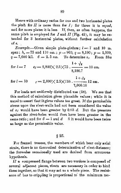
89
Hence with ordinary ratios for one and two horizontal plates
the pitch for II is more than for /; for three it is equal,
and for more plates it is less. If, then, as often happens, the
same pitch is employed for Zand II (Fig. 42), it may be ex-
tended for 3 horizontal plates, without further calclulation
of e.
Example.—Given simple plate-girders ; 1=1 and 10 m.span; 7i =75 and 110 cm.; p = 900, g = 8,100; p= 1,000,
q = 7,000 kil. 8 = 2. 5 cm. To determine ev From 38a
1+tVfor*=7 e7 =2,800X2.5X75. = 10 cm.
8,100.7
forZ=10 T =2,800X2.5X110. 12 cm.7,000.10
For loads not uniformly distributed use (38). "We see that
this method of calculation gives plausible values ; while it is
usual to assert that it gives values too great. If the permissible
stress upon the rivet-walls had not been considered the value
of ei would have been greater by 0.63 d. But the pressure
against the rivet-holes would then have been greater in the
same ratio ; and for 8 = 1 and d 3 it would have been twice
as large as the permissible value.
§25.
For framed trusses, the members of which bear only axial
strain, there is no theoretical determination of rivet-distance;
the formulas occasionally used are derived from erroneous
hypothesis.
If a compressed flange between two vertices is composed of
several adjacent pieces, rivets are necessary in order to bind
these together, so that it may act as a whole piece. The resist-
ance of bar to crippling is proportional to the minimum mo-
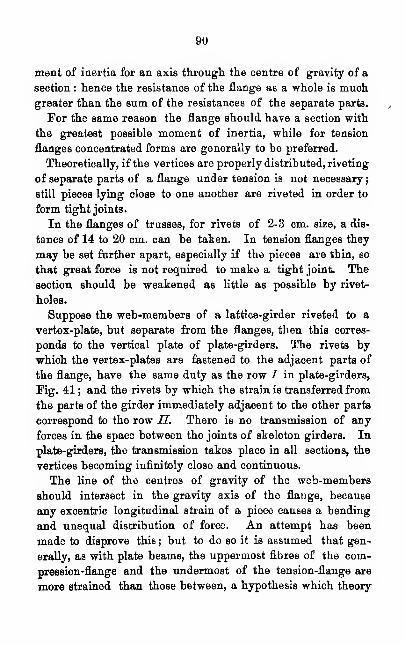
90
ment of inertia for an axis through the centre of gravity of a
section : hence the resistance of the flange as a whole is muchgreater than the sum of the resistances of the separate parts.
For the same reason the flange should have a section with
the greatest possible moment of inertia, while for tension
flanges concentrated forms are generally to be preferred.
Theoretically, if the vertices are properly distributed, riveting
of separate parts of a flange under tension is not necessary
;
still pieces lying close to one another are riveted in order to
form tight joints.
In the flanges of trusses, for rivets of 2-3 cm. size, a dis-
tance of 14 to 20 cm. can be taken. In tension flanges they
may be set further apart, especially if the pieces are thin, so
that great force is not required to make a tight joint. The
section should be weakened as little as possible by rivet-
holes.
Suppose the web-members of a lattice-girder riveted to a
vertex-plate, but separate from the flanges, then this corres-
ponds to the vertical plate of plate-girders. The rivets by
which the vertex-plates are fastened to the adjacent parts of
the flange, have the same duty as the row / in plate-girders,
]?ig. 41 ; and the rivets by which the strain is transferred from
the parts of the girder immediately adjacent to the other parts
correspond to the row II. There is no transmission of any
forces in the space between the joints of skeleton girders. In
plate-girders, the transmission takes place in all sections, the
vertices becoming infinitely close and continuous.
The line of the centres of gravity of the web-members
should intersect in the gravity axis of the flange, because
any excentric longitudinal strain of a piece causes a bending
and unequal distribution of force. An attempt has been
made to disprove this ; but to do so it is assumed that gen-
erally, as with plate beams, the uppermost fibres of the com-
pression-flange and the undermost of the tension-flange are
more strained than those between, a hypothesis which theory
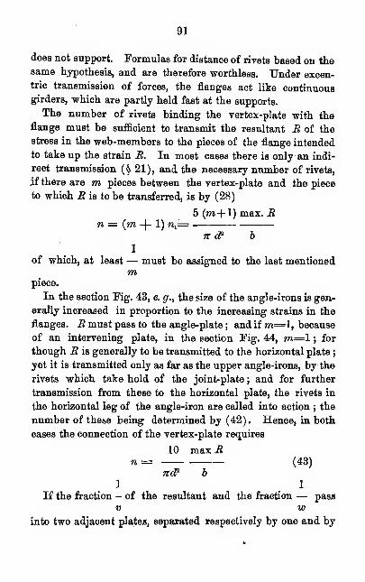
91
does not support. Formulas for distance of rivets based on thesame hypothesis, and are therefore worthless. Under excen-tric transmission of forces, the flanges act like continuousgirders, which are partly held fast at the supports.
The number of rivets binding the vertex-plate with the
flange must be sufficient to transmit the resultant R of the
stress in the web-members to the pieces of the flange intended
to take up the strain R. In most cases there is only an indi-
rect transmission (§ 21), and the necessary number of rivets,
if there are m pieces between the vertex-plate and the piece
to which R is to be transferred, is by (28)
5 (m+1) max. Rn= {m -\- 1) nx
=71 cf 6
1
of which, at least — must be assigned to the last mentionedm
piece.
In the section Kg. 43, e. g., the size of the angle-irons is gen-
erally increased in proportion to the increasing strains in the
flanges. R must pass to the angle-plate ; and if m=l, because
of an intervening plate, in the section Fig. 44, m=l ; for
though R is generally to be transmitted to the horizontal plate ;
yet it is transmitted only as far as the upper angle-irons, by the
rivets which take hold of the joint-plate ; and for further
transmission from these to the horizontal plate, the rivets in
the horizontal leg of the angle-iron are called into action ; the
number of these being determined by (42). Hence, in both
cases the connection of the vertex-plate requires
10 max Rn = (43)
7tcP b
1 1
If the fraction - of the resultant and the fraction — pass
v winto two adjacent plates, separated respectively by one and by
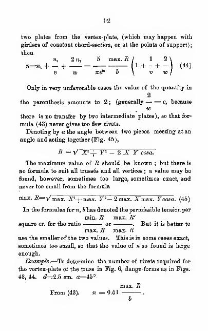
92
two plates from the vertex-plate, (which may happen with
girders of constant chord-section, or at the points of support);
thenwl 2 ny 5 max. R I 1 2 \
n=n, -| H = 1 1 -1 1
)(44)
v w 7td? b \ v w J
Only in very unfavorable cases the value of the quantity in
2
the parenthesis amounts to 2;
(generally — = c, becausew
there is no transfer by two intermediate plates), so that for-
mula (43) never gives too few rivets.
Denoting by a the angle between two pieces meeting at an
angle and acting together (Fig. 45),
R = V X2+ Y 2 - 2 X Y cosa.
The maximum value of R should be known ; but there is
no formula to suit all trusses and all vertices ; a value may be
found, however, sometimes too large, sometimes exact,- and
never too small from the formula
max. R=Vm.&x. JP-|-niax. Y"- 2max. Xmax. Ycosa. (45)
In the formulas for n, b has denoted the permissible tension per
min. R max. R'square cr. for the ratio or . But it is better to
max. R max. Ruse the smaller of the two values. This is in some cases exact,
sometimes too small, so that the value of n so found is large
enough.
Example.—To determine the number of rivets required for
the vertex-plate of the truss in Fig. 6, flange-forms as in Figs.
43, 44. d=2.5 cm. a=45°-
max. RFrom (43). n = 0.51 .
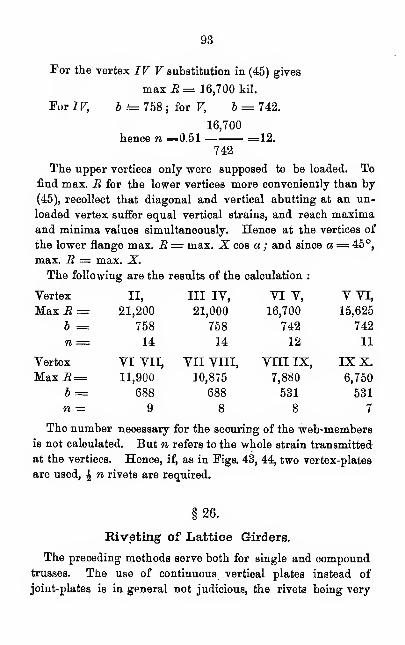
93
For the vertex IV V substitution in (45) gives
maxiJ= 16,700 kil.
For IV, b =- 758 ; for V, b = 742.
16,700
hence n =0.51 =12.742
The upper vertices only were supposed to be loaded. Tofind max. B for the lower vertices more conveniently than by
(45), recollect that diagonal and vertical abutting at an un-
loaded vertex suffer equal vertical strains, and reach maximaand minima values simultaneously. Hence at the vertices of
the lower flange max. B= max. X. cos a ; and since a= 45°,
max. B = max. X.
The following are the results of the calculation :
Vertex
94
regularly affected ; and the vertical-plates at the junctions of
the web-members being disproportionately strained, because at
these points the plate must receive its share of the stress on the
flange, and the differently directed stress of the web-members.
If the web-pieces are set at short intervals, as in lattice trus-
ses, it is often convenient to substitute for the vertex-plates a
continuous vertical-plate. But in that case, because of the un-
favorable strain of the plate, induced by the vertex-plates, the
whole plate should not be referred to the flange, and more
rivets than usual should be employed in the fastening of the
web-members.
The lattice-bars riveted to the vertical plates form a web cor-
responding to the vertical plate of plate-girders. The trans-
mission to the flanges of the force, received by the vertical
plates from the truss bars, takes place no longer at distinct
vertices, but in a continuous way ; so that rivet distances are
determinate.
The rivet pitch of I, Fig. 47, if the flanges are parallel, is
obtained like that of plate-girders, by (87) ; but in this case,
nd* 4.:N= 2 .- b
4 5
2 b
so that ei= -7t d" h . (46)5 max. Vx
b
The value of is (as with continuous girders) least
max. Vxat a point of support ; and hence for the least distance, and
because Vx is of the same sign at all points, for the least rivet-
pitch,
, 1 min. Vm .
6=700 (lH )V 2 max. Va >
95
Towards the middle of the truss or of a span, Vx mayhave a different sign, so that if the rivet-pitch is to vary,
/ *F " \
b = 700 (1
) may be used.V 2 F» '
For simple lattice-girders, with uniformly distributed weight
of structure p, and total load q, we have for the least rivet-
pitch the same value of max. Vx and b as those obtained in
P
1+2?§ 24 ; hence en= 560 n d2 h (46„) in which d, h„ and
ql
ei are in centimeters.
For the rivet-pitch in I, for two rows as in Fig. 47,
2 b
en= n. d* K (47)
5 my max. Vx
exand ea= (48)
my.
in which m is the number of horizontal plates, and y the ratio
of their total section to that of the whole girder.
Equations (46) and (47) are specially applicable to horizontal
flanges. If 'the flange is inclined at any point, the force trans-
1
mitted is times greater ; and the corresponding rivet-
cosa
pitch cosa times less than for the horizontal.
If the flange is of such form that two rows of one-shear
rivets are required for /instead of a single row of two-shear,
the formulas for ex would be the same ; if two rows of two-shear
or four of one-shear are used, then the value of ex should be
96
twice as large ; so the rivet-pitch, for 77 can be determined
without recourse to the general formulas (37), (39).
Example.—For bridges of spans stated, loaded by heavy
locomotives, Schwedler puts p= 800 -|- 301, and thence deduces
the values of g ; parallel flanges.—To find the minimum pitch
for a row of two-shear rivets, Fig. (47) or two rows of one-
shear ; h a being -^ I. d = 2.5 cm.
Substitution in (46a) gives the following figures :
I = 8 10 15 20 30 40 50 m.
p =1,040 1,100 1,2-50 1,400 1,700 2,000 2,300 Ml.
9=9,400 8,400 7,050 7,000 6,900 7,100 7,200
e, = 12.3 13.9 16.9 17.3 17.9 17.7 17.7
For such large values make ei constant along the girder.
§ 27.
Connections at Joints.
The disposition of rivets at joints may differ in cases of tension
and thrust upon the abutting piece. For in the first case the
plate only takes up the strain, while in the second the trans-
mission may be regarded as direct. This would happen only
with perfect contact at joints, which cannot be assumed, and
is not under control. Since the splice-plate must resist lateral
shocks and disturbance it is the ordinary practice to calculate
for the fastenings at joints of members under compression, just
as in the case of tension ; only when the constructive relations
seem to require if, is any diminution made in the length of the
splice-plate or the number of rivets.
Double splice-plates are to be preferred to single. If a
single splice-plate is used for a piece under tension, a couple
tends to bend it and to spring the rivet heads. Single
plates for a piece under compression induce danger of crip-
pling at the joint. These points are of import only for single
riveting; and in many cases, e. g., in that of a flange for which
97
a single splice-plate is necessary, because the other side of the
bar is not free; the adjacent bar preventing bending or crip-
pling. In the latter case it is much worse that a part of the
stress should probably pass not to the splice-plate but into the
abutting rod. At the time of the building of the Britannia
Bridge it was found, by experiment, that pieces so disposed
bore about § of the intended 'stress.
As the splice-plates must receive a strain, as great as that
upon the piece, its useful section must be the same. Gener-
ally double plates need be only half as thick, requiring only
half as many rivets as single, because they are two-shear. The
necessary length of splice-plate diminishes with the necessary
number of rivets, so that double plates are economical. Andthe strain from the rod is distributed more uniformly among
the rivets, the less the number of rivets in the direction of
the strain. In general double plates are the best.
The stress on an abutting piece is communicated to the
splice-plate by the rivets. Since the rivets on each side of the
joint have to bear the same shearing strain as the strain upon
the rod, whatever its nature ; the number of rivets necessary
each side of the joint (Fig. 48, 51) is
5
for single plate, n^ = .F (26)itd2
5
for double plate, ns= .F (27)
2 n d1
These formulas are applicable only when the splice-plates
are in direct contact with the piece. It must not be forgotten
that, if there is between the two an intervening plate, the
splice-plate must have twice as many rivets, and must, there-
fore, be twice as long. This is a case of indirect transmission
of force, and what was said in § 21 applies. It is obvious that
plate II must first take up the strain of I, and that the piece
98
a a serves as splice-plate for I. That this may be possible with-
out over-strain, II beyond a a must have first been released
from the strain, for which n rivets are necessary on each side.
Two plates often joint at the same place. If the joints are
disposed as in Fig. 53, two plates must be set, of the thick-
ness of the plate, and upon each side n rivets. But usually
the joints break ; then the splice-plates need be but half as
thick as the plates, and 1n x + 2«3= 3^ rivets are required;
shown in Fig. 54 ; in which the full line corresponds to the
whole, the dotted line to one-half of the strain P. Lengthen-
ing of the splice-plate (Figs. 54, 55) is not necessary, though
it is sometimes done for convenience.
The necessary number on each side being determined, the
minimum distance along and across the line of direction of the
force from the edge can be determined by the method of § 22.
Care must be taken that the piece be not weakened at the
joint. In the flanges this can always be done ; the net-section
of the rod through the outermost rivet-row / of the splice-plate
(Fig. 56) must not be less than that outside of the connecting
joint ; and the number of rivets must increase per row by, at
the most, as many as stand in row I (§ 22). The net-section
of the splice-plate between the innermost rows must be counted
as its useful section ; if this is diminished its thickness must
be increased.
At the joints of the vertical plates of plate-girders the effect
of weakening is not of so much account ; it is not the practice
to joint where the vertical shearing force and the momentare both of large amount at the same time ; at other points the
plate is always stronger than necessary (§ 17). Still the
number of rivets should be adjusted to the section of the ver-
tical plate, because a uniform distribution of strain upon it is
not to be expected.
As the rivets are double shear
5n= F
2xd2
This would give for strain on one rivet
Ttd* 4iV=2 .-b
4 5
which for thin plate gives too much strain on the holes.
Therefore makeN'= 2d Sb.
hence
N' F
N ' 2d<5
h
2dAfter the most careful disposition of connections at joints,
there may still be weak points. Hence pieces which form any
portion of the structure, as a flange, should never meet at the
same place ; and the joints should be distributed as uniformly
as possible.
APPENDIX.
§ 28.
The Methods of G-erber, Muller and SehafFer.
The first work based upon "Wohler's results was published
in 1872 ; and was adopted by the Bavarian Government as
a "Programme for the Calculations of Iron Constructions."
His fundamental notions were as follows : Suppose a bar of
unit section broken by a resting load. The same effect can be
caused by a strain in part constant (c) ; increasing repeatedly
and very often to a value d. Hencej the difference in strain is
equal to a value t d, and
c-\-td=t= 0d,
G being a co-efficient determined by the conditions.
If Ba is the continued strain, and the passing strain B„ , the
resultant can be reduced to a dead-load by the equation.
Be -\- t Bv= Br = o Bv ,
Br
and F= —
in which br is the permissible strain per sq. unit for resting-
load.
Gerber calls Br the reduced force. The values of r and acan be found for special values of c, d and t, given by Wbhler.
The ratio varies with
o Ba
d Bv
101
To obtain the law of this variation, Gerber puts
c dx=-,y
t t
and represents the relations between x and y by a parabolic
curve. This process determines relations from which the
values of <?, r, corresponding to cp can be found.
Gerber' s formulas also serve for alternating tension andcompression. Bc andHv receive opposite signs, so that cp maybe positive or negative. By _B is signified only the strain of
constant load, by Bv that of live load. If Bc = — Bv ; <p =- 1.
Gerber gives a table of co-efficients for iron of values from
cp = to + 8,720 and — 9,720. In the table they all have
the positive sign ; but it m ust be remembered that Br may not
have the same sign as Bv, but must take that of Bc -\- Bv .
In the application, so as to allow for impact, making max.
Bv 1.5 times the actual live-load, we have
Bc
cp= (A)max. Bv
Find the a corresponding to this cp in the table, hence
Br =0 max. Bv (B)
then F=— (0)
For permanent bridge structures, Gerber makes br = 1,600;
for light structures, br == 2,400.
The total strain Be -j- Bv may be positive as well as nega-
tive; Bv is 1.5 times the live-load ; cp, Br and F must be cal-
culated for both limiting values of Bv ; Bv and F taking op-
posite signs, and the sum of both numerical values ofF giving
the required section.
102
If p is the dead-load and z is 1.5 times the live-load per
running meter,
Bc p<P= = -
max. Bv z
and the actual strain of a flange member is
2
B -|— max. Bv ,
3
hence the permissible strain per square centimeter
2Bc -j- - max. Bc
F2
B™-\— max. Bv
3= 1,600
ff max Bv
2
-+ <p
1,600
6
This gave the figures in the first table of § 30.*
* Gerber's publication does not contain the special application to
flanges. The formulas are given here for the sake of comparison in
§ 30, and to show our view of some doubtful points in his treatment.
Having said that max. Bv is to be calculated for 1.5 times the live-load,
he adds that this value multiplied by r gives the variable stress as a
function of the permanent strain. What t? we ask. Naturally the t
for the corresponding 0. But is to be calculated for' live-load, or
for 1.5 times that quantity? Take it for the latter,
l + <p
b= 1600<p + 1.5 r
103
d o
Schaffer puts x= -; y — - ; finds ^the relation between
t t
them in the same way as Grerber, but differs essentially in
finding the dimensions.
This is his process. Let max. B be the greatest total strain;
min. B the least of the same sign, or the greatest of opposite
sign, then, putting c-\-d=a,
d max. B — min. B
a max. B
in which both, limiting values are to be substituted with signs,
dso that - is always positive.
a
Let max. Bv, min. B„ refer to live-load, Bc to dead-load
;
then, in most cases,
max. B = Be -\- max. Bv
min. B = Be -J- min. Bv
Min. Bv is either zero, or of opposite sign to max Bv ;
d max. Bv — min. Bv
then - =a Bc -\- max. Bv
and with these results, the value of the working resistance (a)
can be found.
If the section is taken so that the strain per square unit is a,
fracture may just take place. Schaffer now attempts to attain
With this formula, I have, by . way of experiment, calculated the
values for the first table in § 30, and found that they are equal at the
extremes, and for other cases they differ by at most 20 kil.
Qerber says, with regard to members under alternating compression
and tension :" From these reduced forces, signs being regarded, the
dimensions may be found." We hope that the above will suffice for
this.
104
the requisite security by regarding the effect of live-load
throughout as n-fold.
The section is calculated as follows :
n (max. Bv— min. Sv)
By moments, ip= {A)
Ba-\- n max. B„
If if> is known, the relation assumed between x and y gives
a fictitious working resistance (for ip is not the actual ratio
n f
- 3ip -fVl3 ip1— 16 f + 16
a = 1 (B)
(2 - ipy
Bc -\- n max. Bv
hence F = ( G)a
The greatest unit-strain is
Bc -\- max. _B„ Bc +n max. Bv
b= = . aF Be -)- n max. B„
r -\-
z
For flanges of girders p = a, p and z being respect-
p-\-nz
ively dead and live-load.
Schaffer makes n = 3.5 or 4. In § 30 the first value is used.
Mtiller starts with the assumption that every strain be-
yond the elastic limit often repeated must cause rupture.
The original strength u is the least strain in one direction
sufficient to cause rupture, and is identical with the ordinary
limit of elasticity. For smaller differences of stress or greater
c
value of - rupture is first possible under the strain a (thed
working-strength); hence, there is an indefinite number of
elastic limits, varying from u to t.
Laying off Wbhler's values of c as abscissas (initial com-
105
pressions negative), and the values of a as ordinates, we obtain
a curve shown in Pig. &7. Miiller prolongs to the c-axis, by
which he determines by " analogy " (how, it does not exactly
appear), the value of the original resistance to compression,
and so completes Wbhler's results.
From this curve for any given ratio
c Ba
<P=-d max. Bv
the value of a can be found, and that of h by introduction
of a safety factor. Miiller employs the. factor \ ; and in this
includes the effects of temperature and of corrosion. He con-
siders that the effect of increase of temperature is the same as
that of a strain producing an equal elongation. It is admitted
that the effects of temperature and stress cannot well be added;
still both take part in the " wear ;" and this compels the reduc-
tion of the absolutely greater strain, under greater permanent
load, because with the presence of other stresses the danger of
reaching the breaking limit is increased.
aSo the value /? = - is modified, for reasons assigned that
uare not quite clear, and which are really unsound, judg-
ing by results ; and a series of values of q> determined by the
completed curve of Wbhler's results, giving b = £ ft u. Miiller
makes u = 1,600, and gives two tables of permissible strains;
one for tension only, the other for alternating tension and com-
pression. It is not recommended to use them.
;§29.
Remarks.
The amount of permissible strain depends upon a general,
but necessarily approximate determination of the relation
between a and the differences in strain. Wbhler's law is the
106
only point of departure, since it alone is of general application,
and correct in all cases.
The special results which he obtained must be employed in
calculation of permissible strains ; but with discrimination and
without accepting them as final;just as was done with
the results of former experiments. Safety co-efficients have
always been, and must always be, employed.
Considering that Wohler's law has not been disputed by
any one, and that it has been recently confirmed by Spangen-,
berg's experiments, it is surprising that a method of calculation,
always conceded to be false and dangerous, should be offically
tolerated. Further experiments are desirable ; but they would
only have a significance like that which a new method of test-
ing tensile strength formerly had ; neither the law nor the
general formulas deduced from it would be altered, We know
already that each material gives its own figures ; and it is
difficult to see, for what special tests we must wait before
adopting the law. For tests on special bridge material?
According to all previous tests it must not be assumed that
smaller differences occur with one kind of metal, than between
different kinds, of well known qualities .(§ § 5, 12); and the
iron tested by Wohler, at least, was not better than that
required for good bridges (§ 13). Or for tests of kinds now
in the market ? Can these be had to-morrow ? No sufficient
reason for not introducing a new method of calculation has
been given thus . far ; and we need not notice those whose
judgment is hindered by their conservatism. Or, shall we wait
till the new method comes from abroad? The question is
not about theoretical crotchets; and the names of the ex-
perienced practical men who have made these investigations
should be sufficient warrant to those who are without expe-
rience. Call for as many co-efficients of safety as you will, the
old method is no longer tenable.
There remains the question of choice between the different
proposed methods. If a new process is to be generally
107
accepted, it must be theoretically sound, simple in application,
and not contradictory to past experience. It is not finally
proven that the working resistance a varies in every kind of
material, according to the same general law ; but, it may bedemanded that actual departures opposed to the general formu-
las, be confined within the limits of the differences of kinds
recognized as good. In all these respects Launhardt's process
is to be preferred. This is primti facie true, and conviction
.comes with more exact testing and comparison of practical cal-
culations. It was after such comparison that we felt that it
was necessary to complete and extend his method.
Launhardt's formula in form (3) is the expression of
Wohler's law. It determines the limiting values of a, and
the only arbitrary element is the choice of the interpolation
formula for aThis choice is confirmed by Wohler's experiments, adapted
to testing only, and besides other by experiments with iron.
Even for more exact results than those which concern us here,
they are sufficient. Further hypothesis and more complex
developments would be superfluous.
Gerber's theory (§ 28) is clear; but the relation between aG
and - is determined in an artificial way. This was necessaryd
in order that the formula might hold for alternation of tension
and compression; but the application in this case is not simple.
Not only must (A), (B), (C) be employed twice, but the whole
previous method of static calculation must be changed. Theeffect of dead-load, and the positive and negative maximumeffects of the live-load must be separately determined for
each piece. This is also true of Schaffer's method, which also
takes too much account of passing load, and none at all of
fixed. His formulas give the security less the greater the
fixed load ; and when this load only is considered, they give
as permissible strain the total ultimate strength t= 3,500.
108
(§ 28; for Bv=o; ip= o, a=t and b— a.) Gerber for dead-load
puts 6=1,600, -which is not exact. Since Schaffer does not
provide safety against fixed load, it happens that sometimes
in case of alternating tension and compression a greater per-
missible value is found than for tension alone, viz : whenever
B -f- max. Bv
600 < aBc
-j- max. Bv
600 n-
a
i. e., for Be> max. B,
a — 600
This happened in one case of the second table of § 30.
When tension, and compression are equal (B) gives an inde-
terminate value.
Muller's process depends in part upon untenable assumptions.
It is not certain that a single increase of temperature has the
same effect as a single load : previous observations are to the
contrary (§ 10). "We have seen that at temperature from 100°
to 200° C, a greater load is borne than at ordinary tempera-
ture, though both effects combine. Even if Muller's hypothesis
were correct, it could not be applied in all cases. For by it
the permissible stress is greater for alternate tension and com-
pression than for tension only and restoration.
The methods of Gerber, Schaffer and Muller agree in this
that they are based too exclusively on Wohler's results. The
last, stripped of unnecessary incidentals is the graphic repre-
sentation of Wohler's numerical results ; and Gerber's and
Schaffer's methods can be made useful only by calculation of
tables which must depend on Wohler's tests ; and it is a
question whether the old tables would be of avail ; but formu-
las I and II are independent of special values, and can be ac-
commodated to new results, while safety-factors can be taken
at will.
Launhardt's view of the effect of impact upon the calculation
109
of permissible stress seems not adequate. He deduces from
Wohler's tests the working strength of iron, not considering
impact,
(5 min. B .
1-|)
6 max. B '
The effects, not local, of impact consist in the most unfavor-
able case of the increase of max. B, which determines the
min. Bsectional area, and the diminution of which diminishes
max. _B
the value of the working-strength. Launhardt takes into ac-
count only the latter by putting
(1 min. Bv
1-|)
2 max. B '
In this way impact is more regarded the greater the value
min. B, and is left out of account when min. B = o, as often
happens. This cannot be meant. Regarding only tension or
compression only, a cannot be less than w=2, 190; but in a
bar alternately pulled and let go partially or wholly, impact
causes in the most unfavorable case alternating tension and
compression, so that the working strength is found by formula
II. Let A B, Fig. 58, be the curve of working-strength, with-
out reference to impacts, then, according to Launhardt, when
these are considered, GD E would take the place of A B, and
when all are taken into account, F G would take the place of
A B. With this, Launhardt would probably agree.
§30.
Comparisons.
The following table contains the permissible strains b, cal-
culated by the new methods for construction-members under
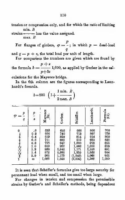
110
tension or compression only, and for which the ratio of limiting
min. Bstrains—. has the value assigned.
max. BP
For flanges of girders, q) = -; in which p = dead-load
1and q = p + z, the total load per unit of length.
For comparison the numbers are given which are found by
the formula b = 1,600, as applied by Gerber in the cal-
p+3z
culations for the Mayence bridge.
In the 6th column are the figures corresponding to Laun-
hardt's formula.
(1 min. B .
1_| )
2 max. B '
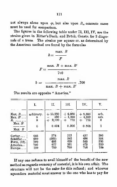
Ill
not always alone upon tp, but also upon B„ concrete casesroust be used for comparison.
The figures in the following table under II, III, IV, are thestrains given in Bitter's Dach. and Briick. Constr. for 3 diago-
nals of a truss. The strains per square cr. as determined bythe American method are found by the formulas
F
b =
112
it. But it cannot be assumed without risk, that permanent
pieces under alternate tension and compression may be sub-
jected to a stress of 700 kil. per square cr. If one does no
more, let him at least use the American formula (p. 7), for
the sections of pieces alternately under tension and compres-
sion, which -gives results fairly agreeing with those obtained
according to Wohler's law from formula (12).

Fig.i. Till. Fig. 3.
mm
p c
Fig. 5.
J

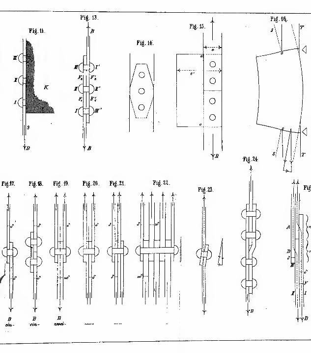
Fig. 11.
Fig. 13.
- -
B
<:r,
<
z? ^
Fig.17. Fig.1&. Fig. 19. Fig. 20. Fig. U.
^)
)C
J-
) Ctn
.. .. .. ..
j- s
) C
«r /
) c
Fig. 15.
Fig. it;
O
O
\ O /
Fig. 2*.
j'
«T
)
Y y >'
5 fl -B
n/i- em- xmeL-
+"i-->
o
o
o
o
'".fl
Fig. 23.
Fig.Ki.
Fig. 24
C
c
c
^)
o
CO
)
^B

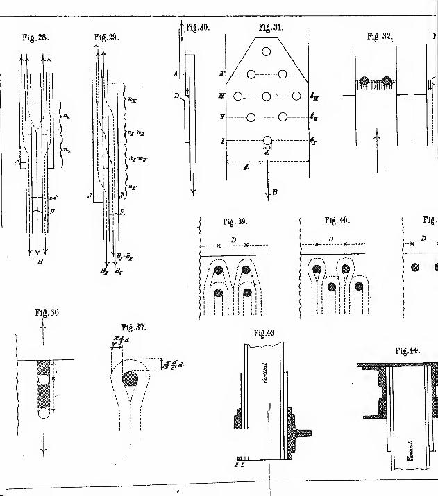
Tig. 28.
>^.. jkA
*«!>
/*
•- .» y-
5
Fig. 36.
14
Fig. 29.
"^r
/"-j
Fig. 37.
£$*
Fig.30.
~!5Z>£rf
Fig. 32.
Fig. 39.
l" \


I
F«.M
Pig. 46.- rY)
Pig. bl.
Jjg^
Fig. 53.
Fig.55.
*<p
snz
Pig. 56.

SCIENTIFIC BOOKSPUBLISHED BIT
D. VAN" JSTOSTKAND,23 Murray Street and 27 Warren Street,
NEW YOEK.
Any Book in this Catalogue, sent free by mail on receipt of price.
Weisbach's Mechanics.Fourth Edition, Revised. 8vo. Cloth. $10.00.
A Manual of Theoretical Mechanics. By Julius Weisbach, Ph. D.
Translated from the fourth augmented and improved German edition,
with an introduction to the Calculus, by Eckley B. Coxe, A. M.,
Mining Engineer. 1100 pages and 902 wood-cut illustrations.
Francis' Lowell Hydraulics.Third Edition. 4to. Clotti. $15.00.
Lowell Hydraulic Experiments—being a Selection from Experi-
ments on Hydraulic Motors, on the Flow of Water over Weirs, and in
open Canals of Uniform Rectangular Section, made at Lowell, Mass.
By J. B. Francis, Civil Engineer. Third edi tion, revised and enlarged,
includitig many New Experiments on Gauging Water in Open Canals,
and on the Flow through Submerged Orifices and Diverging Tubes.
With 23 copperplates, beautifully engraved, and about 100 new pages
of text.
Kirkwood on Filtration.
4to. Cloth. $15.00.
Report on the Filtration of River Waters, for the Supply of
Cities, as practised in Europe, made to the Board of Water Commis-
sioners of the City of St. Louis. By James P. KiRjcwoor. Illustra-
teu oy 30 double-plate engravings.
2 SCIENTIFIC BOOKS PUBLISHED BY
Rogers' Geology of Pennsylvania.3 Vols. 4to, with Portfolio of Maps. Cloth. $30.00.
The Geology of Pennsylvania. A Government Survey. With a gen-
eral view of the Geology of the United States, Essays on the Coal For-
mation and its Fossils, and a description of the Coal Fields of North
America and Great Britain. By Henry Darwin Rogers, Late State
Geologist of Pennsylvania. Splendidly illustrated with Plates and En-
gravings in the Text
Merrill's Iron Truss Bridges.Third Edition. 4to. Cloth. $5.00.
Iron Truss Bridges for Railroads. The Method of Calculating
Strains in Trusses, with a careful comparison of the, most prominent
Trusses, in reference to economy in combination, etc., etc. By Bvt.
Col. William E. Merrill, U.S.A., Corps of Engineers. Nine litho-
graphed plates of illustrations.
Shreve on Bridges and Roofs.8vo, 87 wood-cut illustrations. Cloth. $5.00.
A Treatise on the Strength op Bridges and. Hoofs—comprising
the determination of Algebraic formulas for Strains in Horizontal, In-
clined or Rafter, Triangular, Bowstring, Lenticular and other Trusses,
from fixed and moving load*, with practical applications and examples,
for the use of Students and Engineers. By Samuel H. Shreve, A. M.,
Civil Engineer.
The Kansas City Bridge.4to. Cloth. $6.00
•,Vith an Account of the Regimen of the Missouri River,—and
a description of the Methods used for Founding in that River. By O.
Chanute, Chief Engineer, and George Morison, Assistant Engineer.
Illustrated with five lithographic views and twelve plates of plans.
Clarke's Quincy Bridge.4to. Cloth. $7.50.
Description of the Iron Railway. Bridge across the Mississippi
River at Quincy, Illinois. By Thomas Curtis Clarke, Chief Engineer.
With twenty-one lithographed plans.
D. VAN NOSTRAND.
Whipple on Bridge Building.
New edition. 8vo. Illustrated. Cloth. $4.
Ax Elementary and Practical Treatise on Bridge Building.
By S. Whipple, C. E.
Roelbling's Bridges.Imperial folio. Cloth. $25.00.
Long and Short Span Railway Bridges. By John A. Roebling,
C. E. With large copperplate engravings of plans and views.
DiTbois' Graphical Statics.
Svo. 60 Illustrations. Cloth. $2.00.
The New Method of Graphical Statics. By A. J. Dubois, C. E.,
Ph. D.
Greene's Bridge Trusses.8vo. Illustrated. Cloth. $2.00.
Graphical Method for the Analysis of Bridge Trusses,—ex-
tended to Continuous Girders and Draw Spans. By Charles E. Greene,
A. M., Professor of Civil Engineering, University of Michigan. Illus-
trated by three folding plates.
Bow on Bracing.156 Illustrations on Stone. 8vo. Cloth. $1.50.
A Treatise on Bracing,—with its application to Bridges and other
Structures of Wood or Iron. By Robert Henry Bow, C. E.
Stoney on Strains.
New and Kevised Edition, with numerous illustrations. Royal Svo, 684 pp.
Cloth. $12.50.
The Theory of Strains in Girders—and Similar Structures, with
Observations on the Application of Theory to Practice, and Tables of
Strength and other Properties of Materials. By Bindon B. Stoney,
B. A."
Hem-ici's Skeleton Structures.
Svo. Cloth. $1.50.
Skeleton Structures, especially in their Application to the building
of Steel and Iron Bridges. By Olaus Henkici.
4 SCIENTIFIC BOOKS PUBLISHED BY
Burgh's Modern Marine Engineering.One thick 4to vol. Cloth. $25.00. Half morocco. $30.00.
Modern Marine Engineering, applied to Paddle and Screw Propul-
sion. Consisting of 36 Colored Plates, 259 Practical Wood-cut Illus-
trations, and 403 pages of Descriptive Matter, the whole being an ex-
position of the present practice of the following firms : Messrs. J. Peun& Sons ; Messrs. Maudslay, Sons & Field-; Messrs. James Watt & Co.
;
Messrs. J. & G. Rennie; Messrs. R. Napier & Sons; Messrs. J. & W.Dudgeon ; Messrs. Ravenhill & Hodgson ; Messrs. Humphreys & Ten-
ant ; Mr. J. T. Spencer, and Messrs. Forrester & Co. By N. P. Burgh,Engineer.
\
King's Notes on Steam.Nineteenth Edition. 8vo. $2.00.
Lessons and Practical Notes on Steam,—the Steam Engine, Propel-
lers, &c, &c, for Young Engineers. By the late W. R. King, U. S. N.
Revised by Chief-Engineer J. W. King, IT. S. Navy.
Link and. Valve Motions, by W. S.Auchincloss.
Sixth Edition. 8vo. Cloth. $3.00.
Application of the Slide Valve and Link Motion to Stationary,
Portable, Locomotive and Marine Engines. By William S. Auchin-
closs. Designed as a hand-book for Mechanical Engineers. Dimen-
sions of the valve are found by means of a Printed Scale, and propor-
tions of the link determined without the assistance of a model. With37 wood-cuts and 21 lithographic plates, with copperplate engraving of
the Travel Scale.
Bacon's Steam-Engine Indicator.12mo. Cloth. $1.00 Mor. $1.50.
Treatise on the Richards Steam-Engine Indicator,—with
directions for its use. By Charles T. Porter. Revised, with notes
and large additions as developed by American Practice, with an Ap-
pendix containing useful formula? and rules for Engineers. By F. W.Bacon, M. E., Illustrated. Second Edition.
Isherwood's Engineering Precedents.Two Vols, in One. 8vo. Cloth. $2.50.
Engineering Precedents for Steam Machinery.—By B. F Isiier-
wood, Chief Engineer, U. S. Navy. With illustrations.
D. VAX XOSTRAND.
Slide Valve by Eccentrics, by Prof. C. W. Mac-Cord.
;
4to. Illustrated. Cloth, $3.00
A Practical Treatise on the Slide Valve by Eccentrics,—examining by methods the action of the Eccentric upon the Slide
Valve, and explaining the practical processes of laying out the movements,adapting the valve for its various duties in the steam-engine. Eor the
use of Engineers, Draughtsmen, Machinists, and Students of valve
motions in general. By C. W. MacCord, A. M., Professor of
Mechanical Drawing, Stevens' Institute of Technology, Hoboken, N. J.
Stillman's Steam-Engine Indicator.12mo. Cloth. $1.00
The Steam-Engine Indicator,—and the Improved Manometer Steam
and Vacuum Gauges ; their utility and application. By Paul Still-
man. New edition.
Porter's Steam-Engine Indicator.Third Edition. Revised and Enlarged. 8vo. Illustrated. Cloth. $3.50.
A Treatise on the Richards Steam-Engine Indicator,—and the
Development and Application of Force in the Steam-Engine. ByCharles T. Porter.
McCulloch's Theory of Heat.8vo. Cloth. $3.50.
A Treatise on the Mechanical Theory op Heat, and its
Applications to the Steam-Engine. ByProf. R. S. McCulloch,
of the Washington and Lee University, Lexington, Va.
Van Buren's Formulas.8vo. Cloth. $2.00.
Investigations of Formulas,—for the Strength of the Iron parts of
Steam Machinery. By J. D. Van Buren, Jr., C. E. Illustrated.
Stuart's Successful Engineer.13mo. Boards. 50 cents.
How to Become a Successful Engineer. Bsing Hints to Youths
intending to adopt the Profession. By Bernard Stuart, Engineer.
Sixth Edition.
6 SCIENTIFIC BOOKS PUBLISHED BY
Stuart's Naval Dry Docks.Tweuty-four engravings on steel. Fourth edition. 4to. Cloth. $6.00.
The Naval Dry Docks of the United States. By Charles B.
Stuart, Engineer in Chief U. S. Navy.
Ward's Steam for tlie Million.
8vo. Cloth. 11.00.
Steam for the Million. A Popular Treatise on Steam and its
Application to the Useful Arts, especially to Navigation. By J. H.
Ward, Commander U. S. Navy.
Tunner on Roll-Turning.1 vol. 8vo. aud 1 vol. folio plates. 110.00.
A Treatise ox Roll-Turxino for the Manufacture of Iron,
by Peter Tunner. Translated by John B. Pearse, of the Penn-
sylvania Steel Works. With numerous wood-cuts, 8vo., together with
a folio atlas of 10 lithographed plates of Rolls, Measurements, &c.
Gruner on Steel.
8\-o. Cloth. $3.50.
The Manufacture of Steel. By M. L. Gruner ; translated from
the French. By Lenox Smith, A.M., E.M. ; with an Appendix on
the Bessemer Process in the United States, by the translator. Illus-
trated by lithographed drawings and wood-cuts.
Barha on the Use of Steel.
12mo. Illustrated. Cloth. $1.50.
The Use of Steel in Construction. Methods of Working, Apply-
ing, and Testing Plates and Bars. By J. Barba, Chief Naval
Constructor. Translated from the French, with a Preface, by A. L.
HOLLEY, P.B.
Bell on Iron Smelting.8vo. Cloth. $6.00.
Chemical Phenomena of Iron Smelting. An experimental and
practical examination of the circumstances which determine the
capacity of the Blast Furnace, the Temperature of the Air, and the
Proper Condition of the Materials to be operated upon. By
I. Lowtiiian Bell.
D. VAN iXUSTJl.l.VD.
The Useful Metals and their Allocs ; Scoffren,Truran, and. othei's.
Filth Edition. 8vo. Half calf . $3.75.
The Useful Metals and theik Alloys, employed in the conver-
sion of Iron, Copper, Tin, Zinc, Antimony, and Lead Ores,
with their applications to the Industrial Arts. By John Scof-
frex, William Truran, William Clay, Robert Oxland,
William Fairbairn, W. C. Aitkin, and William Vose Pickett.
Collins' Useful Alloys.18mo. Flexible. 75 cents.
The Private Book of Useful Alloys and Memoranda for Gold,
smiths, Jewellers, etc. By James E. Collins.
Joynson's Metal Used in Construction.12mo. Cloth. 75 cents.
The Metals Used in Construction . Iron, Steel, Bessemer Metal,
etc., etc. By Francis II. Joynson. Illustrated.
Dodd's Dictionary of Manufactures, etc.12nio. Cloth. $1.50.
Dictionary of Manufactures, Mining, Machinery, and the
Industrial Arts. By George Dodd.
Von Cotta's Ore Deposits.
8vo. Cloth. $4.00.
Treatise on Ore Deposits. By Bernhard Von Cotta, Professor
of Geology in the Royal School of Mines, Freidburg, Saxony. Trans-
lated from the second German edition, by Frederick Prime, Jr.,
Mining Engineer, and revised by the author ; with numerous illus-
trations. .'
Plattner's Blow-Pipe Analysis.
Third Edition. Revised. 568 pages. 8vo. Cloth. $5.00.
Plattner's Manual of Qualitative and Quantitative Analy-
sis with the Blow-Pipe. From the last German edition, Revised
and enlarged. By Prof. Tn. Richter, of the Royal Saxon Mining
Academy. Translated by Professor II . B. Cornwall ; assisted by
John H. Caswell. With eighty-seven wood-cuts .and Lithographic
Plate.

SCIENTIFIC HOOKS PUBLISHED BY
Plympton's Blow-Pipe Analysis.12mo. Cloth. $1.50.
Tub Blow-Pipe: A Guide to its Use in the Determination of Salts
and Minerals. Compiled from various sources, by Gkokge W.Plymptox, C.E., A.M., Professor of Physical Science in the Polytech-
nic Institute, Brooklyn, N.Y.
Pynchon's Chemical Physics.New Edition. Revised and enlarged. Crown 8vo. Cloth. $3.00.
Introduction to Chemical Physics ; Designed for the Use of
Academies, Colleges, and High Schools. Illustrated -with numerous
engravings, and containing copious experiments, with directions for
preparing them. By Thomas Ruggles Pynchon. M.A., President
of Trinity College, Hartford.
Eliot and. Storer's Qualitative ChemicalAnalysis. '
New Edition. Revised. 12mo. Illustrated. Cloth. $1.50.
A Compendious Manual of Qualitative Chemical Analysis.
By Charles W. Eliot and Frank H. Storer. Revised, with
the cooperation of the Authors, by William Kipley Nichols,
Professor of Chemistry in the Massachusetts Institute of Technology.
Rammelsberg's Chemical Analysis.Svo. Cloth. $2.25.
Guide to a Course op Quantitative Chemical Analysis,
Especially of Minerals and Furnace Products. Illustrated
by Examples. By C. F. Rammelsberg. Translated by J. Towler,M.D. ~
Naqnet's Legal Chemistry.Illustrated. 12mo. Cloth. $2.00.
Legal Chemistry. A Guide to the Detection of Poisons, Falsifica-
tion of Writings, Adulteration of Alimentary and Pharmaceutical
Substances ; Analysis of Ashes, and Examination of Hair, Coins,
Fire-arms, and Stains, as Applied to Chemical Jurisprudence. For
the Use of Chemists, Physicians, Lawyers , Pharmacists, and Experts.
Translated, with additions, including a List of Books and Memoirs
on Toxicology, etc., from the French of A. Naquet. By J. P.
Battershall, Ph. D., with a Preface by C. F. Chandler, Ph. D.,
M.D..LL.D
T). VAX yOS TitA XV.
Prescott's Proximate Organic Analysis.12rao. Clotli. $1.75.
Outlines op Proximate Organic Analysis, for the Identification,
Separation, and Quantitative Determination of the more commonly
occurring Organic Compounds. By Albert B. Prescott, Professor
of Organic and Applied Chemistry in the University of Michigan.
Prescott's Alcoholic Liquors.12mo. Cloth. 91.50.
Chemical Examination of Alcoholic Liquors.—A Manual of the
Constituents of the Distilled Spirits and Fermented Liquors of Com-
merce, and their Qualitative and Quantitative Determinations. ByAlbert B. Prescott, Professor of Organic and Applied Chemistry
in the University of Michigan.
Pope's Modern Practice of the ElectricTelegraph.
Ninth Edition. 8vb. Cloth. $2.00.
•A Hand-book for Electricians and Operators. By Frank L. Pope.
Ninth edition. Revised and enlarged, andfully illustrated.
Sabine's History of the Telegraph. .
Second Edition. 12mo. Cloth. $1.25.
History and Progress of the Electric Telegraph, with De-
scriptions of some of the Apparatus. By Robert Sabine, C.E.
Haskins' Galvanometer.Pocket form. Illustrated. Morocco tucks. $2.00.
The Galvanometer, and its Uses ;—A Manual for Electricians
and Students. By C. II. Haskins.
Myer's Manual of Signals.
New Edition. Enlarged. 12mo. 4S Plates, full Roan. $5.00.
Manual of Signals, for the Use of Signal Officers in the Field. By
Brig.-Gen. Albert J. Myer, Chief Signal Officer of the Army.
Larrabee's Secret Letter and Telegraph18mo. Cloth. $1.00.
j
Cinier and Secret Letter and Telegraphic Code, -with Hogg's
Improvements. By C S. Larrabee.
10 SCIENTIFIC BOOKS PUBLISHED BY
Gillmore's Limes and. Cements.Fifth Edition. Revised and Enlarged. 8vo. Cloth. $4.00.
Practical Tkeatise on Limes, Hydraulic Cements, and Mor-tars. By Q. A. Gillmore, Lt.-Col. U. S. Corps of Engineers.
Brevet Major-General U. S. Army.
Grillmore's Coignet Beton.Nine Plates, Views, etc. 8vo. Cloth. $2.50.
Coignet Beton and Other Artificial Stone.—By Q. A. Gill-
more, Lt.-Col. U. S. Corps of Engineers, Brevet Major-General U.S.
Army.
G-illmore on Roapls.
Seventy Illustrations. 12mo. Cloth. $2.00.
A Practical Treatise on the Construction of Roads, Streets,
and Pavements. By Q. A. Gillmore, Lt.-Col. U. S. Corps of
Engineers, Brevet Major-General U. S. Army.
Grillmore's Building Stones.8vo. Cloth. $1.50.
Effort on Strength of the Building Stones in thb UnitedStates, etc.
Holley's Railway Practice.
1 vol. folio. Cloth. $12.00.
American and European Railway Practice, in the EcuioiMcal
_Generation of Steam, including the materials and construction of
Coal-burning Boilers, Combustion, the Variable Blast, Vaporization,
Circulation, Super-beating, Supplying and Heating Feed-water, &c,
and the adaptation of Wood and Coke-burning Engines to Coal-
burning ; and in Permanent Way, including Road-bed, Sleepers,
Rails, Joint Fastenings, Street Railways, etc., etc. By Alex-inker
L. Holley, B.P. With 77 lithographed plates.
Useful Information for Railway Men.Pocket form. Morocco, gilt. $2.00.
»
Compiled by W. G. Hamilton, Engineer. Sixth Edition, Revised
and Enlarged. 570 pages.

I). VAN NUSTHAND. 11
Stuart's Civil and. Military Engineering ofAmerica.
8vo. Illustrated. Cloth. $5.00.
The Civil and Militaky Engineers oir America. By General
Charles B. Stuart, Author of " Naval Dry Docks of the United
States," etc., etc. Embellished with nine finely-executed Portraits
on steel of eminent Engineers, and illustrated by Engravings of some
of the most important and original works constructed in America.
Ernst's Manual of Military Engineering.103 Wood-cuts and 3 Lithographed Plates. . 12mo. Cloth. $5.00
A Manual of Practical Military Engineering. Prepared for
the use of the Cadets of the U. S. Military Academy, and for Engineer
Troops. By Capt. (>. II. Ernst, Corps of Engineers, Instructor in
Practical Military Engineering, U. S. Military Academy.
Simms' Levelling.
12mo. Cloth. $8.50.
A Treatise on the Principles and Practice op Levelling,
showing its application to purposes of Railway Engineering and the
Construction of Roads, etc. By Frederick W. Simms, C.E. From
the fifth London edition, Revised and Corrected, with the addition of
Mr.' Law's Practical Examples for Setting-oat Railway Curves.
Illustrated with three lithographic plates and numerous wood-cuts.
Jeffers' Nautical S^^l'•veying.
Illustrated with 9 Copperplates and 31 Wood-cut Illustrations. 8vo. Cloth. $5.00.
Nautical Surveying. By William N. Jeki-krs. Captain U. S.
Navy.
Brunnow's Spherical Astronomy.Illustrated. 8vo. Cloth. $6.00.
Spherical Astronomy. By P. Brunnow, Ph. Dr. Translated by
the Author from the second German edition.
The Plane Table.
8vo. Cloth. $2.00.
[ts Uses in Topographical Surveying. From the papers of the
U. S. Coast Survey.
12 SCIENTIFIC BOOKS PUBLISHED BY
Cnauvenet's Lunar Distances.8vo. Cloth. 12.00.
New Method of Correcting Lunar Distances, and Improved
Method of Finding the Error and Hate of a Chronometer, by equal
altitudes. By Wi. Chauvenet, LL.D. , Chancellor of Washington
University of St. Louis.
Burt's Key to Solar Compass.Second Edition. Poclcet-book form. Tack. $2.50.
Key to the Solar Compass, and Surveyor's Companion ; comprising
all the Rules necessary for use in the Field ; also Description of the
Linear Surveys and Public Land System of the United States, Notes
on the Barometer, Suggestions for an Outfit for a Survey of Four
Months, etc. By W. A. Burt, U. S. Deputy Surveyor.
Howard's Earthwork Mensuration.8vo. Illustrated. Cloth. $1.50.
Earthwork Mensuration on the Basis op the PrismoidalFormulas. Containing simple and labor-saving method of obtaining
Prismoidal Contents directly from End Areas. Illustrated by
Examples, and accompanied by Plain Rules for practical uses. ByConway R. Howard, Civil Engineer, Richmond, Va.
Morris' Easy Rules.T8 Illustrations. 8vo. Cloth. $1.50.
Easy Rules for the Measurement or Earthworks, by means of
the Prismoidal Formula. By Elwood Morris, Civil Engineer.
Clevenger's Surveying.Illustrated Pocket Form. Morocco, gilt. $2.50.
A Treatise on th-k Method of Government Surveying, as
prescribed by the U. S. Congress and Commissioner of the General
Land Office. With complete Mathematical, Astronomical, and Prac-
tical Instructions for the use of the U. S. Surveyors in the Field, and
Students who contemplate engaging in the business of Public Laud
Surveying. By S. V. Clevengf.r, U. S. Deputy Surveyor.
Hewson on Embankments.8vo. Cloth. $2.00.
Principles and Practice of Embanking Lands from River
Floods, as applied to the Levees of the Mississippi, J?y WilliamHewson, Civil Engine1
)'
D. VAN NOSTRAND. IV
MinifLe's Mechanical Drawing.Ninth Edition. Itoyal Svo. Cloth. $4.00.
A Text-Book op Geometrical Drawing, for the use of Mechanicsand Schools. With illustrations for Drawing Plans, Sections, andElevations of Buildings and Machinery
; an Introduction to Isometri-
cal Drawing, and an Essay on Linear Perspective and Shadows.With over 200 diagrams on steal. By William Minifie, Architect.
With an Appendix on the Theory and Application of Colors.
Minifie's Geometrical Drawing.New Edition. Enlarged. 12mo. Cloth. $2.00.
Geometrical Drawings. Abridged from the octavo edition, for the
use of Schools. Illustrated with 48 steel plates.
Free Hand Drawing.Profusely Illustrated. 18mo. Boards. 50 ceuts.
A Guide to Ornamental, Figure, and Landscape Drawing. By au
Art Student.
The Mechanic's Friend.12mo. Cloth. 300 Illustrations. $1.50.
The Mechanic's Friend. A Collection of Receipts and Practical
Suggestions, relating to Aquaria—Bronzing—Cements—Drawing
—
Dyes—Electricity—Gilding—Glass-working—Glues—Horology— Lac-
quers—Locomotives—Magnetism—Metal-working— Modelling— Pho-
tography—Pyrotechny—Railways— Solders— Steam-Engine — Tele-
graphy—Taxidermy—Varnishes—Waterproofing—and Miscellaneous
Tools, Instruments, Machines, and Processes connected with the.
Chemical and Mechanical Arts. By William E. Axon, M.R. S.L. ,
Harrison's Mechanic's Tool-Book.44 Illustrations. 12mo. Cloth. $1.60.
Mechanics' Tool Book, with Practical Rules and Suggestions, for the
use of Machinists, Iron Workers, and others. By W. B. Harrison.
Randall's Quartz Operator's Hand-Book.12mo. Cloth. $2.00.
Quartz Operator's Hand-Book. By P. M. Randall. 2Woiiiioii, Revised and Enlarged. Fully illustrated.
14 SC1EKT1F1C HUOKS PUBLISHED BY
Joynson on Machine Grearing.8vo. Cloth. $2.00.
The Mechanic's and Student's Guide in the designing and Con"
structionof General Machine Gearing, as Eccentrics, Screws, Toothed
Wheels, etc., and the Drawing of Rectilineal and Carved Surfaces.
Edited by Francis H. Joynson. With 18 folded plates.
Silversmith's Hand-Book.Fourth Edition. Illustrated. I2mo. Cloth. $3.00.
A Practical Hand-Book for Miners, Metallurgists, and Assayers.
By Julius Silversmith. Illustrated.
Barnes' Submarine Warfare.8vo. Cloth. $5.00.
Submarine Warfare, Defensive and Offensive. Descriptions
of the various forms of Torpedoes, Submarine Batteries and Torpedo
Boats actually used in War. Methods of Ignition by Machinery,
Contact Fuzes, and Electricity, and a full account of experiments
made to determine the Explosive Porce of Gunpowder under Water.
Also a discussion of the Offensive Torpedo system, its effect upon
Iron-clad Ship systems, and influence upon future Naval Wars. ByLieut.-Com. John S. Barnes, U.S.N. With twenty lithographic
plates and many wood-cuts.
Foster's Submarine Blasting.4to. Cloth. $3.50.
Submarine Blasting, in Boston Harbor, Massachusetts—Removal of
Tower and Corwin Bocks. By John G. Foster, U. S. Eng. and
Bvt. Major-General U. S. Army. With seven plates.
Mowbray's Tri-Nitro-Glycerine.8vo. Cloth. Illustrated. $3.00
TriNitro-Glycerine, as applied in the Hoosac Tunnel, and. to Sub-
marine Blasting, Torpedoes, Quarrying, etc.
Williamson on the Barometer.4to. Cloth. $15.00.
On ras Use of the Barometer on Surveys and Reconnais-
sances. Part I.—Meteorology in its Connection with Hypsometry.
Part II.—Barometric Hypsometry. By R. S. Williamson, Bvt.
Lt.-Col. U. S. A., Major Corps of Engineers. With illustrative tables
and engravings.
D. VAN NOSTitAND. \b
Williamson's Meteorological Tables.4to. Flexible Cloth. $2.50.
Practical Tables in Meteorology and Hypsometry, in connectionwith the use of the Barometer. By Col. K. S. Williamson, U.S.A.
Butler's Projectiles and. Rifled. Gannon.4to. 36 Plates. Cloth. $7.50.
Projectiles and Rifled Cannon. A Critical Discussion of thePrincipal Systems of Rifling and Projectiles, with Practical Sugges-tions for their Improvement. By Capt. John S. Butler, OrdnanceCorps, U. S. A.
Benet's Chronoscope.Second Editiou. Illustrated. 4to. Cloth. $3.00.
Electro-Ballistic Machines, and the Schultz Chronoscope. ByLt.-Col. S. V. Benet, Chief of Ordnance U. S. A.
Miuhaelis' Chronograph.4to. Illustrated. Cloth. $3.00.
The Le Boulenge Chronograph. With three lithographed folding
plates of illustrations. By Bvt. Captain O. E. Michaelis, Ordnance
Corps, U. S. A.
Nugent on Optics.12mo. Cloth. $1.50.
Treatise on Optics ; or, Light and Sight, theoretically and practically
treated ; with the application to Fine Art and Industrial Pursuits.
By E. Nugent. With 103 illustrations.
Peirce's Analytic Mechanics.4to. Cloth. $10.00.
System of Analytic Mechanics. By Benjamin Peirce, Pro-
fessor of Astronomy and Mathematics in Harvard University.
Craig's Decimal System.Square 32mo. Limp. 50c.
Weights and Measures. An Account of the Decimal System, with
Tables of Conversion for Commercial and Scientific Uses. By B. F.
Craig, M.D.
10 SCIENTIFIC BOOKS PUBLISHED BY
Alexander's Dictionary ofWeights andMeasures.
New Edition. Svo. Cloth. $3.50.
Universal Dictionary of Weights and Measures, Ancient and
Modern, reduced to the standards of the United States of America.
By J. H. Alexander.
Elliot's European Light-Houses.51 Engravings and 21 Wood-cuts. 8vo. Cloth. $5.00.
European Light-House Systems. Being a Report of a Tour of
Inspection made in 1873. By Major George H. Elliot, U. S.
Engineers.
Sweet's Report on Coal.With Maps. 8vo. Cloth. $3.00.
Special Report on Coal. By S. H. Sweet.
Oolburn's Gas Works of London.12mo. Boards. GO cents.
Gas Works of London. By Zerah Colburn.
Walker's Screw Propulsion.8vo. Cloth. 75 cents.
Notes on Screw Propulsion, its Rise and History. By Capfc. W. II.
Walker, U. S. Navy.
Pook on Shipbuilding.8vo. Cloth. Illustrated. $5.00.
Method of Preparing me Lines and Draughting Vessels
Propelled by Sail or Steam, including a Chapter on Laying-off
on the Mould-loft Floor. By Samuel M. Pook, Naval Constructor.
Saeltzer's Acoustics.12uao. Cloth. $2.00.
Treatise -on Acoustics in connection with Ventilation. By Alex-ander Saeltzer.
Pickert and Metcalf's Art of Graining.lvol. 4to. Tinted Paper. Cloth. $10.00.
The Art of Graining, with description of Colors and their Applica-
tion. By Charles Pickert and Abraham Metcalf. With 42
tinted plates of the various woods used in interior finishing.

D. VAX XUSTUA.XJX 17
Wanklyn's Milk Analysis.12mo. Cloth. '$1.00.
Milk Analysis. A Practical Treatise on the Examination of Milk,
and its Derivatives, Cream, Butter, and Cheese. By J. AlfuedWanklyn.M.R.C.S.
Rice & Johnson's Differential Functions.
Paper,12 mo. 50 cents.
On* a New Method of Obtaining the Differentials ov Func-tions, 'with especial reference to the Newtonian Conception of Rates
or Velocities. By J. Minot Rice, Prof, of Mathematics, U. S. Navy,
and W. Woolsey Johnson, Prof, of Mathematics, St. John's
College, Annapolis.
Coffin's Navigation.Fifth Edition. 12mo. Cloth. 13.50.
Navigation and Nautical Astronomy. Prepared for the use of
the U. S. Naval Academy. By J. II. C. Coffin, Professor of
Astronomy, Navigation and Surveying ; with 52 wood-cut illustra-
tions.
Clark's Theoretical Navigation,
8vo. Cloth. $3.00.
Theoretical Navigation and Nautical Astronomy. By Lewis
Clark, Lieut.-Commander, U. S. Navy. Illustrated with 41 wood-
cuts, including the Vernier.
Toner's Dictionary of Elevations.
8vo. Paper, $3.00 Cloth, $3,75.
Dictionary of Elevations and Climatic Register of the
United States. Containing, in addition to Elevations, the Latitude,
Mean Annual Temperature, and the total Annual Rain Fall of many
Localities ; with a brief introduction on the Orographic and Physical
Peculiarities of North America. By J. M. Tonek, M.D.
SCIENTIFIC BOOKS PUBLISHED BY
VAN NOSTEAND'S SCIENCE SERIES.It is the intention of the Publisher of this Series to issue them at
intervals of about a month. They will be put up in a uniform, neat,
and attractive form, 18mo, fancy boards. The subjects will be of an
eminently scientific character, and embrace as wide a range of topics as
possible, all of the highest character.
Price, 50 Cents Each.
I. Chimneys for Furnaces, Fire-places, and Steam Boilers. ByR. Armstrong, C.E.
II. Steam Boiler Explosions. By Zerah Colburn.
III. Practical Designing of Retaining Walls. By Arthur Jacob,
A.B. With Illustrations.
IV. Proportions of Pins Used in Bridges. By Charles E.
Bender, C.E. With Illustrations.
V. Ventilation of Buildings. By W. F. Butler. With Illustrations.
VI. On the Designing and Construction of Storage Reservoirs.
By Arthur Jacob. AVith Illustrations.
VII. Surcharged and Different Forms of Retaining Walls.By James S. Tate, C.E.
VIII. A Treatise on the Compound Engine. By JonN Turnbull.With Illustrations.
'
IX. Fuel. By C.William Siemens, to which is appended the value of
Artificial Fuels as Compared with Coal. By John Worm-
ald, C.E.
X. Compound Engines. Translated from the French of A. Mallet.Illustrated.
XI. Theory of Arches. By Prof. W. Allan, of the Washington and
Lee College. Illustrated.
XIT. A Practical Theory of Voussoir Arches. By William Cain,
C.E. Illustrated.
D. VAN NOSTBAND. 19
XIII. A Practical Treatise ox the Gases Met With in CoalMines. By the late J. J. Atkinson, Government Inspector of
Mines for the County of Durham, England.
XIV. Friction of Air in Mines. By J. J. Atkinson, author of " APractical Treatise on the Gases met with in Coal Mines."
XV. Skew Arches. By Prof. E. W. Hyde, C.E. Illustrated with
numerous engravings and three folded plates.
XVI. A Graphic Method for Solving Certain Algebraic Equa-
tions. By Prof. George L. Vose. With Illustrations.
XVII. Water and Water Supply. By Prof. W. H. Corfield,
M.A., of the University College, London.
XVIII. Sewerage and Sewage Utilization. By Prof. W. H.
Corfield, M.A., of the University College, London.
XIX. Strength of Beams Under Transverse Loads. By Prof.
W. Allan, author of "Theory of Arches." With Illustrations
XX. Bridge and Tunnel Centres. By John B. McMasters,
C.E. With Illustrations.
XXI. Safety Valves. By Richard H. Buel, C.E. With Illustra-
tions.
XXII. High Masonry Dams. By John B. McMasters, C.E.
With Illustrations.
XXIII. The Fatigue of Metals under Repeated Strains, with
various Tables of Results of Experiments. From the German of
Prof. Ludwig Spangenberg. With a Preface by S. H. S breve,
A.M. With Illustrations. •
XXIV. A Practical Treatise on the Teeth of Wheels, with
the theory of the use of Robinson's Odontograph. By S. W. Robin-
son, Prof, of Mechanical Engineering, Illinois Industrial University.
XXV. Theory and Calculations of Continuous Bridges. By
Mansfield Merriman, C.E. With Illustrations.
20 D. VAX XOSTilAXD.
The University Series.
No. 1.—On the Physical Basis of Life. By Prof. T. EL Huxley,LL.D., F.R.S. With an introduction by a Professor in Yale College.
12mo, pp. 36. Paper cover, 25 cents.
No. 2.
—
The Corelation of Vital and Physical Forces. ByProf. George F. Barker, M.D., of Yale College. 36 pp. Papercovers, 25 cents.
No. 3.- -As Regards Protoplasm, in relation to Prof. Huxley'sPhysical Basis of Life. By J. Hutchinson Stirling, T.R.C.S.72 pp., 25 cents.
No. 4.—On the Hypothesis of Evolution, Physical and Meta-physical. By Prof. Edward D. Cope. 12mo, 72 pp. Paper covers,
25 cents.
No. 5.—Scientific Addresses:—1. On the Methods and Tendenciesof Physical Investigation. 2. On Haze and Dust. 3. On the Scien-tific Use of the Imagination. By Prof. John Tyndall, F.R.S.12mo, 74 pp. Paper covers, 25 cents. Flex, cloth, 50 cents.
No. 6.
—
Natural Selection as Applied to Man. By AlfredRussell Wallace. This pamphlet treats (1) of the Divelopemsutof Human Races under the Law of Selection
; (2) the Limits of
Natural Selection as applied to Man. 54 pp. 25 cents.
No. 7.—Spectrum Analysis. Three Lectures by Profs. Roscoe,Huggins and Lockyer. Finely Illustrated. S3 pp. Paper covers,25 cents.
No. 8.—The Sun. A sketch of the present state of scientific opinionas regards this body. By Prof. C. A. Young, Ph. D. of DartmouthCollege. 58 pp. Paper covers, 25 cents.
No. £.—The Earth a Great Magnet. By A. M. Mayer, Ph. D.,of Stevens' Institute. 72 pp. Paper covers, 25 cents. Flexiblecloth, 50 cents.
No. 10.—Mysteries of the Voice axd Ear. By Prof. O. N.' Rood,Columbia College, New York. Bsautifully Illustrated. 38 pp.Paper covers, 25 cents.
Odd Volume Crown Svo, 183 pages, illustrated, price $2 CO.
LEGAL CHEMISTRY:A GUIDE
TO THE
DETECTION OF POISONS, EXAMINATION OF STAINS, ETC.,
AS' APPLIED TO
CHEMICAL JURISPRUDENCE.
Translated with Additions from the French of A. Naquet, Pro-fessor to the Faculty of Medicine of Paris.
By J. P. BATTERSHALL, Nat. Sc. D.
WITH A PREFACE BY
C. F. CHANDLER, Ph.D., M.D., LL.D.
PREFA CE
.
The importance of exact chemical analysis in a great variety of cases which comebefore the courts is now fully recognized, and the translation of this excellent little
book on Legal Chemistry, by one of the most distinguished French Chemists, will beappreciated by a large class of American readers who are not able to consult theoriginal. While it is to be regretted that the author has not presented a much morecomplete work, there is an advantage in the compact form of this treatise which com-pensates, in some degree, for its brevity.
The translator has greatly increased the value of the book by a few additions andhis copious index, and especially by the lists of works and memoirs which he hasappended ; and while he could have further increased its value by additions fromother authors, we recognize the weight of the considerations which induced him topresent it in the form given to it by the author. Some chapters will have very little
value in this country at this day, tout Ijhe translator could not, with propriety, omitanything oontained in the original. C. J?. C.
" This is one of the most valuable and practical works issued on this subject, con-taining in a small compass nearly everything required."—Jfew York Eclectic MedicalJournal.
" This book on Legal Chemistry is the vade meeum indispensable to the doctor,the lawyer, and the judge, called to discuss criminal cases of that kind, which havebecome so frequent of late."—Commercial Advertiser.-
" This little work will be found very valuable as a guide to ordinary medicalexperts, and gives very explicit directions for the chemical examinations necessaryfor the discovery of a large list of poisons, mineral and vegetable ; also the examina-tion of fire-arms, writings, ashes for human remains, adulteration in food, medicines,etc., etc."— Cliieago Medical Timis.
Morocco Tuck, Pocketbook Style, Gilt Edges,tions. $2 50.
246 pp. 307 Illustra-
FORMULAS & TABLESFOR
ARCHITECTS AND ENGINEERS,In Calculating the Strains and Capacity of Structures in Iron and Wood.
BY F. SCHUMANN, C.E.
PREFACE.The following collection of Formulas and Tables is intended as a
ready reference for Architects and Engineers in computing the Strains andStrength of Structures in Iron or Wood. The author has attempted to
give concisely all the necessary data required for the calculations. Theobject is, to give a compilation and transformation into simple formulasand tables, adapted to practice, of matter contained in the works of Weis-
bach, Banhbie, Rebhahn, Ritter, Breyman, Gordon, Brandt, Moll & Reuleaux,
Laissle & ISchubler, Fairbairn, and others.
Among other matter may be particularly mentioned the tables giving
the capacity of rolled and cast iron beams, and the extensive table of for-
mulas for the Moment of Inertia and Resistance of various sections. Theformulas and constants for ascertaining the Strains in Eoof and other
Trusses will be found quite complete, extending to all the different formsor systems in general use. Under "Miscellaneous" is given necessary
formulas for the calculation of Lines, Areas, and Solids ; also tables of
Natural Sinss, Co3ine3, Tangents, Cotangents, Secants and Cosecants,
Area and Circumference of Circles, "Weight of Materials, etc.
Summary of Definitions and GeneralPrinciples.
Moments of Inertia and Resistance of Va-rious Sections.
Strength of Materials, etc.
Resistance to Cross Breaking and Shear-ing.
Capacity and Strength of Beams.Pressure on Supports.Compressive Strains and Pressure oaSupports.
Sloping Beams, Rafters, etc.
Resistance to Crushing.Strength of Columns, Hilars, and Struts.Parallelogram of Forces.Strains in Frames.Strains in Boom Derricks.Strains in Trusses.Strains in Trussed Beams.Strains in Trusses with Parallel Booms.Strains in Parabolic Curved Trusses.Bow-String Girders.Capacity and Strength of Parabolic ArchedBeams or Bibs Originally Curved.
Strains in a Polygonal Frame.Strains in Roof Trusses.Pressure of Wind on Roofs.Pressure of Snow on Roofs.Tie Rods and Bars.
Joints or Connections in Iron ConstructionDimensions of Bolts and Nuts.Compound Strain in Horizontal and Slop-ing Beams.
Weight of Moving Loads.Static and Moving Loads on Bridges ofWrought Iron.
Geometry.Centre of Gravity of Planes.Trigonometrical Formulas.Trigonometrical Functions.Circumference, Area, and Cubic Contentsof Circles.
Srftciflc Gravities of Materials.Weight of Superficial Inch ofWrought andCast Iron.
Weight per Square Foot of Metals.Weight of a Lineal Foot of Flat and SquareBar Iron.
Weight of a Lineal Foot of Rolled RoundIron.
Weight of Bolts, Nuts, and Heads.Weight of Material used in Building.Divisions of a Foot expressed in Equiva-lent Decimals.
Table for Comparing Measures andWeights of Different Countries.
To cut the s-trongest and Stiffest Beamfrom a Log.
On Vol. 12mo, 203 pages, 103 Illustrations, price $1 SO.
ATEEAIISEONOPIICS;OR, LIGHT AND SIGHT
THEORETICALLY AND PRACTICALLY TREATED
WITH THE APPLICATION TO
FINE AET AND INDUSTRIAL PUESUITS.
E. IUGENT, O.E.
CONTENTS.Chap. I. Introductory.
II. Retraction of Light.II I., Refraction of Rays by Prisms and Lenses.IV. Formation of Images by Lenses.V. On the Reflection of Light.VI. Formation of Images by Plane, Concave, and Convex Mirrors
—
Reflecting Telescopes—Reflecting Microscopes.VII. On Spherical Aberrations in Lenses and Mirrors.VIII. On Caustic Curves formed by Reflection and Refraction.IX. Physical Optics—Analysis of Eight—Its Decomposition into
Colors.X. On the Dispersion of Light.XI. On the Principle of Achromatic Telescopes.XII. Breadth of Waves of Light—Inflection or Defraction of Light
—
Law of Interference.XIII. Double Refraction and Polarization of Light.XIV. The Eye.XV. Accidental or Complementary Colors.XVI. Optical Instruments.XVII. The Principles of Optics applied to Various Useful Furpcsee.
NOTICES OF THE PRESS." This book is of a practical rather than of a theoretical kind, and is designed to
afford accurate and complete information to all interested in the application of thescience."
—
Hound Table.
" This is a work not only of service as a college text-book, but eminently useful
to the photographer, the painter, the house-decorator, the tailor, the outfitter, the
sculptor, the builder, the stone-cutter, the mason, the draughtsman , the architect,
the engineer—in short, almost every department of human industry."
—
Cincinnati
Chronicle.
One Volume, 339 pages, with numerous Diagrams and
Wood-Cuts, handsomely hound in, fine cloth, $1 50.
THE
MECHANICS' FRIEND.KDITED BY
WM. E. A. AXON, M.K.S.L.
A COLLECTION OF
RECEIPTS AND PRACTICAL SUGGESTIONSRELATING TO
The Metric System, Miscellaneous Tools, Instruments and Processes,
Cements and Glues, Varnislies and Lacquers, Solders and Metal-
Working, Steam-Engines, Mailways and Locomotives, Fire-
Arms, Horology, Glass, Wood- Working, House and Gar-
den, Drawing and Moulding, Photography, MusicalInstruments, Taxidermy, Plant Preserving,
Aquaria, Miscellaneous Chemical Pro-cesses and Compositions, Lighting,
Dyes, Water-proofing, Gildingand Bronzing, Pyrotechny,
Electricity, Magnetism,and Telegraphy.
EXTRACT PEOM PREFACE.The present differs In some important particulars from the many " receipt-books "
which hare preceded it. It is the result not so much of individual judgment as of theaction of a numberof " friends in council," whose practical experiences have^inspiredthe instructions and hints it contains. . . . There is a large apd rapidly-increas-ing class of amateurs who devote some of their leisure to working in the mechanicaland other branches of practical science. These persons will, it is hoped, in thisvolume find many things to 'save them trouble and speed them on their way. Whetherthey want to skeletonize the leaf of a plant, or to construct a steam propeller for amodel boat, to make a sky-rocket or an electric clock, an artificial magnet or a photo-graphic handkerchief, they will not look in vain. The tendency to the traditional inevery trade renders it probable that with persons of this class many improved pro-cesses will originate. The amateur workman looks at things with a fresher eye thanone who has come to regard the processes learned in youth as the final of perfection.... In preparing for the press the contributions of so many individuals, a con-siderable amount of revision and condensation hasbeen necessary, and every possiblecare has been taken to exclude matter already easily accessible. . . . The topicshave, as far as possible, been grouped together according to their mutual relation-ship, but as all such attempts at classification are in their very nature defective, thisarrangement has been supplemented by a copious alphabetical index.
" In the various receipts that are scattered throughout the work, the reader willfind sufficient amount of valuable material to reimburse him for the oost of the book,and there are numerous ingenious and useful mechanical devices, which are fullyfigured and explained. 11—Industrial Monthly.
"It is an invaluable book of reference for practical and amateur mechanics andartisans, and all who are interested in oxperimental science. 1*—American rmgress,New Twit.