Embed Size (px)
Citation preview
NASA CONTRACTOR
RE’PORT
STRENGTH CHARACTERISTICS OF COMPOSITE MATERIALS
by Stephen W. Tsm
Prepared under Contract No. NAS 7-215 by
PHILCO CORPORATION
Newport Beach, Calif.
f OY
NATIONAL AERONAUTICS AND SPACE ADMINISTRATION l WASHINGTON, D. C. l APRIL 1965
https://ntrs.nasa.gov/search.jsp?R=19650012040 2018-09-06T06:42:39+00:00Z

NASA CR-224
STRENGTH CHARACTERISTICS OF COMPOSITE MATERIALS
By Stephen W. Tsai
Distribution of this report is provided in the interest of information exchange. Responsibility for the contents resides in the author or organization that prepared it.
Prepared under Contract No. NAS 7-215 by PHILCO CORPORATION
Newport Beach, Calif.
for
NATIONAL AERONAUTICS AND SPACE ADMINISTRATION
For sale by the Clearinghouse for Federal Scientific and Technical Information Springfield, Virginia 22151 - Price $4.00
II.
I I I . , a--- . , . . . . - . . . - -m- .- . . . . -- --- .- . -- . ~ ._ -

FOREWORD
This is an annual report of the work done under the National
Aeronautics and Space Administration Contract NAS 7-215, “Structural
Behavior of Composite Materials, ” for the period January 1964 to
January 1965. The program is monitored by Mr. Norman J. Mayer,
Chief, Advanced Structures and Materials Application, Office of Advanced
Research and Technology.
The author wishes to acknowledge the contributions of his colleague
Dr. Victor D. Azzi, and his consultants Dr. George S. Springer of the
Massachusetts Institute of Technology, and Dr. Albert B. Schultz of the
University of Delaware. Mr. Rodney L. Thomas’ contribution in the
experimental work, and Mr. Douglas R. Doner and Miss Alena Fong’s
contributions in the numerical analysis and computation are also
acknowledged.
. . . 111
ABSTRACT
The strength characteristics of quasi-homogeneous, nonisotropic
materials are derived from a generalized distortional work criterion. For
unidirectional composites, the strength is governed by the axial, transverse,
and shear strengths, and the angle of fiber orientation.
The strength of a laminated composite consisting of layers of uni-
directional composites depends on the strength, thickness, and orientation of
each constituent layer and the temperature at which the laminate is cured.
In the process of lamination, thermal and mechanical interactions are induced
which affect the residual stress and the subsequent stress distribution under
external load.
A method of strength analysis of laminated composites is delineated
using glass-epoxy composites as examples. The validity of the method is
demonstrated by appropriate experiments.
Commonly encountered material constants and coefficients for stress
and strength analyses for glass-epoxy composites are listed in the Appendix.
iv
CONTENTS
SECTION PAGE
1 INTRODUCTION
2 STRENGTH OF ANISOTROPIC MATERIALS
Mathematical Theory . . . . . . Quasi-homogeneous Composites . . . Experimental Results . . . . . .
3 STRENGTH OF LAMINATED COMPOSITES
Mathematical Theory . . . . . . Cross-ply Composites . . . . . . Angle-ply Composites . . . . . .
Structural Behavior of Composite Materials . Scope of Present Investigation . . .
4 CONCLUSIONS . . . . . . . . . .
REFERENCES . . . . . . . . . . . .
APPENDIX. . . . . . . . . . . . . .
.
. 1 2
5 7
13
19 28 43
53
57
59
V
ILLUSTRATIONS
Figure 1. Comparative Yield Surfaces . . . . . . . . . . . . 8
Figure 2. Coordinate Transformation of Stress .......... 9
Figure 3. Tensile Test Specimens ............. 14
Figure 4. Strength of Unidirectional Composites ......... 16
Figure 5. Strength of a Typical Cross-ply Composite ....... 37
Figure 6. Strength of Cross-ply Composites .......... 39
Figure 7. Thermal Warping of a Two-layer Composite ...... 40
Figure 8. Strength of Angle-ply Composites .......... 51
vi

NOMENCLATURE
A.. = A 1J
= In-plane stiffness matrix, lb/in.
:C A:
lj = A:’ = Intermediate in-plane matrix, in. /lb
A.’ . = A’ 1J
= In-plane compliance matrix, in. /lb
B.. = B 1J
= Stiffness coupling matrix, lb
g: B.. = B’
iJ = Intermediate coupling matrix, in.
B!. = B’ 1J
= Compliance coupling matrix, 1 /lb
C.. 13
= Anisotropic stiffness matrix, psi
D.. = D = Flexural stiffness matrix, lb-in. iJ
Df:. = D”: = Intermediate flexural matrix, lb-in. iJ
D!. = D’ 1J
= Flexural compliance matrix, l/lb-in.
E = Young’s modulus, psi
E11 = Axial stiffness, psi
9: H.‘. = Hz”
1J = Intermediate coupling matrix, in.
h = Plate thickness, in.
M. =M
M;
= Distributed bending (and twisting) moments, lb
= MT = Thermal moment, lb
Kri =m = Effective moment = Mi + MT
m = cos 0, or
= cross-ply ratio (total thickness of odd layers over that of even layers)
vii

NOMENCLATURE (Continued)
N. = N
N;
= Stress resultant, lb/in.
= NT = Thermal forces, lb/in.
FT. =fi 1
= Effective stress resultant = Ni + NT
n 1 sin 8, or
= total number of layers
P = Ratio of normal stresses = a2/ 01
9 = Ratio of shear stress = as/ 01
r = Ratio of normal strengths = X/Y
S = Shear strength of unidirectional composite, psi
S = Shear strength ratio = X/s
‘ij = Anisotropic compliance matrix, l/psi
T = Temperature, degree F
T+ = Coordinate transformation with positive rotation
T- = Coordinate transformation with negative rotation
X = Axial strength of unidirectional composite, psi
Y = Transverse strength of unidirectional composite, psi
a. 1
= Thermal expansion matrix, in. /in. /degree F
f. 1 = Strain component, in. /in.
0 F .
1 = In-plane strain, component, in. /in.
viii

8
K. 1
x
u. 1
r iJ
u
u 12
v21
NOMENCLATURE (Continued)
= Fiber orientation or lamination angle, degree
= Curvature, I/in.
= 1 - V12 v21
= Stress components, psi
= Shear stress, psi
= Poisson’s ratio
= Major Poisson’s ratio
= Minor Poisson’s ratio
SUPERSCRIPTS
t = Positive rotation or tensile property
= Negative rotation or compressive property
k = k-th layer in a laminated composite
-1 = Inverse matrix
SUBSCRIPTS
1, J = I, 2, . . . 6 or x, y, z in 3-dimensional space, or
= 1, 2, 6 or x, y, s in 2-dimensional space
ix
SECTION 1
INTRODUCTION
Structural Behavior of Composite Materials
The purpose of the present investigation is to establish a rational
basis of the designs of composite materials for structural applications.
Ultimately, materials design can be integrated into structural design as an
added dimension. Higher performance and lower cost in materials and
structures applications can therefore be expected.
Following the research method outlined previously, 1*
the present
program combines two traditional areas of research - materials and
structures. These two areas are linked by a mechanical constitutive equa-
tion, the simplest form of which is the generalized Hooke’s law. The mate-
rials research is concerned with the influences of the constituent materials
on the coefficients of the constitutive equation, which in this case, are the
elastic moduli. The structures research, on the other hand, is concerned
with the gross behavior of an anisotropic medium. An integrated structural
design takes into account, in addition to the traditional variations in thick-
nesses and shapes, the controllable magnitude and direction of material
properties through the selection of proper constituent materials and their
geometric arrangement.
“References are listed at the end of this report.
1
Following the framework just described, the elastic moduli of aniso-
tropic laminated composites were reported previously. 2, 3 The appropriate
constitutive equation was:
This equation, of course, included the quasi-homogeneous orthotropic com-
posite, which represented a unidirectional composite, as a special case.
The material coefficients A, B, and D were expressed in terms of material
and geometric parameters associated with the constituent materials and the
method of lamination. This information provided a rational basis for the
design of elastic stiffnesses of an anisotropic laminated composite. Thus,
the investigation reported in References 2 and 3 involved both structures
research, in the establishment of Equation (1) as an appropriate constitutive
equation, and materials research, in the establishment of the parameters
that govern the material coefficients of Equation (1).
The present report covers the strength characteristic of anisotropic
laminated composites, which again includes the quasi-homogeneous com-
posite, as a special case. Unlike the case of the elastic moduli, the present
report covers only the structures aspect of strengths; the materials aspect
is to be investigated in the future. The appropriate constitutive equation for
the strength characteristics is established in this report. Only when this
information is available, can the area of research from the materials stand-
point be delineated. Guidelines for the design of composites from the
strength consideration can be derived.
Scope of Present Investigation
The present investigation is concerned with the structures aspect of
the strength characteristics of composite materials. The strength of a
quasi-homogeneous anisotropic composite is first established. Then the
strength of a laminated composite consisting of layers of quasi-homogeneous

composites bonded together is investigated. The validity of the theoretical
predictions is demonstrated by using glass-epoxy resin composites as test
specimens.
The main result of this investigation is that a more realistic method
of strength analysis than the prevailing netting analysis is obtained. The
structural behavior of composite materials is now better understood, and one
can use these materials with higher precision and greater confidence. A
stride is made toward the rational design of composite materials. Although
much more analyses and data generation still remain to be done, the present
knowledge of stiffnesses and strengths of composite materials, as reported
in References 2 and 3, and in this report, respectively, is approaching the
level of knowledge presently available in the use of isotropic homogeneous
materials.

SECTION 2
STRENGTH OF ANISOTROPIC MATERIALS
Mathematical Theory
Several strength theories of anisotropic materials are frequently
encountered in the study of composite materials. Hill postulated a theory in
1q484 and later repeated it in his plasticity book. 5 Using his notation, it is
assumed that the yield condition is a quadratic function of the stress
components
2f ( oij) = F ( uy - oz)’ t G ( oz - ox)2 f H(Ox - ~7~) 2
(2)
t2L r 2 t 2M r 2
YZ Z;t2Nr =1
XY
where F, G, H, L, M, N are material coefficients characteristic of the
state of anisotropy, and x, y, z are the axes of material symmetry which
are assumed to exist. This yield condition is a generalization of von Mises’
condition proposed in 1913 for isotropic materials. Note that Equation (2)
reduces to von Mises’ condition when the material coefficients are equal.
Beyond this necessary condition, there seems to be no further rationale.
Nevertheless, this yield condition has the advantages of being reasonable
and readily usable in a mathematical theory of strength because it is a con-
tinuous function in the stress space. For identification purposes, this con-
dition will be called the distortional energy condition.
Marin proposed’ a strength theory equivalent to Equation (2), except
the principal stress components were used instead of the general stress
components. The use of principal stresses is, in fact, more difficult to
apply to anisotropic materials, since the axes of material symmetry, the
principal stress, and the principal strain are, in general, not coincident.
Thus, principal stresses per se do not have much physical significance.
Another strength theory of anisotropic material is called the “inter-
action formula, ” as described by a series of reports by the Forest Products
Laboratory 7, 8, 9 and apparently independently by Ashkenazi. 10 The interaction
formula in Hill’s notation” takes the following form:
ux 2 ( ) - -
X “,-> + (Y$)2t(+Y)2=1
plates,
( ) 2
3. - Y
*y; + ($)2 t (.+,” = 1
uz ( > 2
- - Z
y$ + (rz)2t (LE)’ = 1
(3)
Since the composite material of interests now is in the form of thin
a state of plane stress is assumed. Then Equations (2) and (3) can
be reduced, respectively:
z& $ (3)’ f (Tgq2 = 1 (4)
. I ,
-‘The shear strengths used here are a, R, S rather than R, S, T, in order to spare T for temperature.
6
ux 2 ( ) - - X
y$J + .(Y+)2 + (+q” = 1
OY 2
( ) Y =l
OX
( )
2 x =1
(5)
The difference between the yield condition of distortional energy, the inter-
action formula, and von Mises is shown in Figure 1, assuming tensile and
compressive strengths of the materials are equal.
For the present program, it is assumed that the distortional energy
condition is valid. This, of course, will be substantiated experimentally
later in this report. It is also assumed, for the present, that failure by
yielding and by ultimate strength are synonymous. This will be shown to be
reasonable for glass-epoxy composites, which exhibit linearly elastic
behavior up to failure stress with little or no yielding. The work contained
in the Forest Product reports 728, 9 and Askenazi 10 had two restrictions:
(1) no differentiation was made between the homogeneous and laminated com-
posite, (2) shear strength was not treated as an independent strength prop-
erty. In the present investigation, both these restrictions are removed.
Quasi-homogeneous Composites
The strength of quasi-homogeneous anisotropy composites was
reported by Azzi and Tsai. 11
For the sake of completeness, the essential
points of this reference are repeated here.
It is the purpose of this section to demonstrate how the distortional
energy condition can be applied to a quasi-homogeneous anisotropy composite
subjected to combined stresses. One of the basic assumptions of this condi-
tion is that there exist three mutually perpendicular planes of symmetry
within the anisotropy body. This means that the body is really orthotropic
rather than generally anisotropic from the point of view of strength. Under
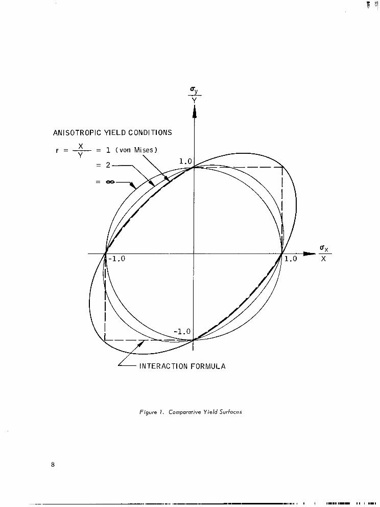
ANISOTROPIC YIELD CONDITIONS
r =
- INTERACTION FORMULA
Figure I. Comporotive Yield Surfaces

this assumption, the yield condition must be applied to the state of stress
expressed in the coordinate system coincident with that of the material
symmetry. Thus, the state of stress imposed on a body must be transformed
to the coordinate system of material symmetry and then the yield condition
applied. Let x-y be the material symmetry axes, and l-2, the reference
coordinate axes of the externally applied stresses, the usual transformation
equation 12 in matrix form is:
UX
uY
us
=
2 2 n 2 mn
2 n m2 -2 mn
.
2 2 -mn mn m -n
O1
u2
O6
(6)
where m = cos 8, n = sin 8, and positive 0 is shown in Figure 2.
Figure 2. Coordinate Transformation of Stress
9

_-. .._ -..- .-. ---
For convenience, the following notations are used:
(7)
Substituting the notations in Equations (6) and (7) into the yield condition in
the form of Equation (4), one obtains:
1: 1 - p + p2r2 + q’s2 1 m4 + 2 q [ 3-P - 2 pr2 f (p - 1) s2 1 m3n
+ I: 8 q2 + 2 (p + 2 q2) r2 + (p - 1)2 (s2 - 1) -2 q’s2 1 m2n2
(8)
f2q (p - 1) s”] mn3 t b” 2 2 -p+r’+q s I
n4
= (X/ ul)’ = (rY/ 01)’ = (sS/o,)’
This result may be summarized as follows: For a given anisotropic body in
reference coordinates 1-2, specified by X, Y (or r), and S (or s), with a
given orientation of the material symmetry axes, 0, and subjected to com-
bined stresses ol, o2 (or p) and a6 (or q), the magnitude of the applied
stress 0 1’ at failure, can be determined by solving Equation (8) for ul.
Alternatively, Equation (8) may be regarded as the transformation equation
for the strength of a quasi-homogeneous anisotropic material subjected to
combined stresses; i. e., the strength characteristics as a function of the
orientation of the symmetry axes, 8.
For uniaxial tension, p = q = 0, the failure condition is
m4+ (s 2 - 1) m2n2 f r2n4 = (X/ alI2
or
C 112
7 = X/ m4+ (S2 - 1) m2n2 + r2n4 1
(9)
(10)
10

Thus, by performing uniaxial tension tests on specimens with different
orientations of the material symmetry axes; i. e., different values of 0, one
finds directly the transformation property of strength. What is equally
important is that the strength characteristics of a quasi-homogeneous aniso-
tropic material under combined stresses are simultaneously verified. By a
simple substitution of Equation (6) into (q), while maintaining p = q = 0, one
recovers, as expected, the original yield condition shown in Equation (4).
Equation (8) can be reduced to other simple cases in a straight-
forward manner. For example, the case of hydrostatic pressure requires
p = 1, q = 0, from which one can show that the maximum pressure is equal
to the transverse strength, Y, and is independent of the orientation, 8.
The case of an internally pressurized cylindrical shell is described
by p = 2, q = 0, from which Equation (8) reduces to
(4 r2 - 1) m4 -I- (4 r2 - 1 + s2) m2n2 + (r2 + 2) n4 = (X/ 9)’ (11)
For isotropic material, it can be shown that
which agrees with von Mises’ condition. 5 Equation (11) then reduces to
u1 = x/J3
and (12)
u2 = 2 x/ J3 = 1.155 x
which is the well-known result between the maximum hoop stress U 5
2 and the
uniaxial strength X.
11

The case of pure shear can be derived by letting o1 = o2 = 0 in
Equation (6), and then by substituting it into Equation (4), ” one obtains
4 m2n2 (r2 + 2)/s’ 22
+ (m2 - n ) = (s/ O6)’ (13)
or
c I 112 u6 = S/ 4 m2n2 (r2 + 2)/s’ + (m2 - n2)’
It is interesting to note that:
when 8 = O” or 90°, u6 = S
when 8 = k45O ,
9: :: l/2 1
u6
- Y, if r >> 1
(14)
(15)
(16)
= X/&if r = 1 (isotropy)
In conclusion, it is seen that the distortional energy condition can be
easily applied to cases frequently encountered in the design and use of aniso-
tropic composites. The strength characteristics involve the axial, trans-
verse and shear strengths, X, Y, and S, respectively, and the orientation of
the material symmetry axes, 0 , This strength theory is quite different from
the netting analysis, which is still used extensively in the filament-winding
industry. The inaccuracy of netting analysis as a theory or design criterion
is far less damaging per se than the influence of its erroneous implications
on many recent and even current research programs on filament-winding.
9: ‘Equation (8) cannot be used directly for this case because Ol is equal to
zero. 4: .‘< 1 1 This is the shear strength used in Marin’s theory.
6 It is a derived quantity, as opposed to X, Y, and S, which are the “principal strengths. ”
12

Experimental Results
In the preceding subsection, the utility from the mathematical stand-
point of yield condition as applied to a quasi-homogeneous anisotropic com-
posite has been outlined. In this subsection, experimental results which
demonstrate the validity of the proposed theory of strength will be reported.
The specimens used were made of unidirectional glass-filaments
preimpregnated with epoxy resin. This material is supplied by the U.S.
Polymeric Company with a designation of E-787-NUF.” The curing cycle
involved no preheat, 50 psi pressure, and 300°F temperature for 2 hours
followed by slow cooling. Tensile test specimens were cut from the cured
panels using a wet-bladed masonry saw. As it was found that specimens
of uniform cross section had a tendency to fail under the grips at low angles
of fiber orientation, a diamond-coated router was used to shape specimens
with a reduced test section, in “dog-bone” fashion. Approximate specimen
dimensions were (in inches): overall length, 8. 00; overall width, 0.450;
length of test section, 2. 50; width of test section, 0. 180; thickness, 0. 125.
A 3 -inch-radius circular arc, tangent to the test section, connected the test
section to the maximum end section. Additionally, aluminum tabs (a cata-
logue item) were bonded to the ends of the specimens to distribute the loads
imposed by the grips. A special fixture was devised: (1) to align the tabs
with the specimens to ensure application of pure axial load, and (2) to be
capable of making up to 20 individual specimens simultaneously. Sample
specimens, before and after test, are shown in Figure 3.
The values of the axial and transverse normal strengths X and Y for
the material employed were determined from simple tension tests of speci-
mens having fiber orientations of 0 and n/2 to the direction of applied stress,
respectively. The shear strength S was determined from the simple torsion
test of a filament-wound thin-walled torsion tube having all circumferential
winding s.
“The same material was used to make test specimens reported in Reference 2.
13
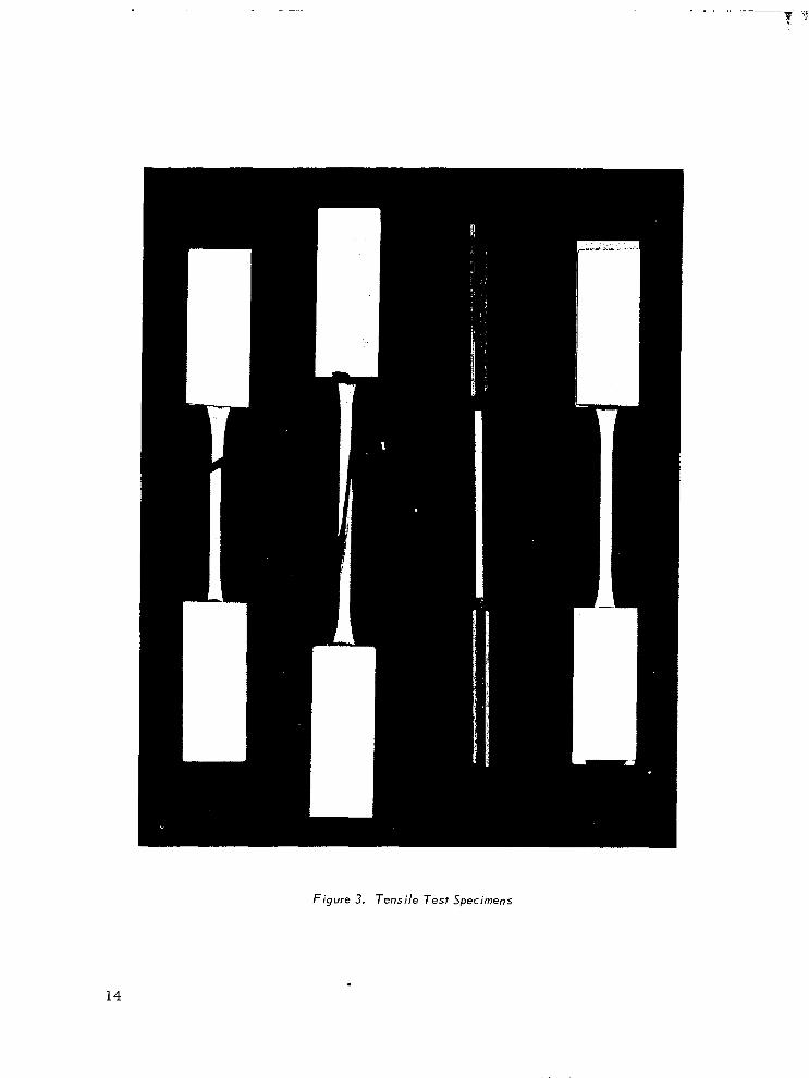
Figure 3. Tensile Test Specimens
. 14
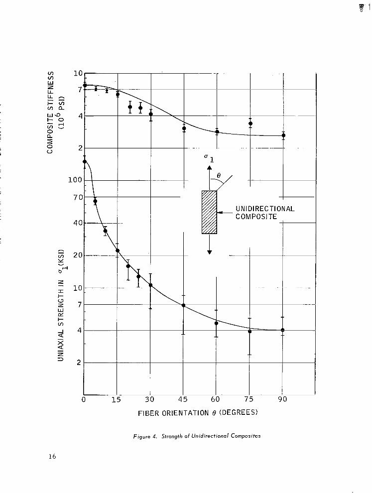
To verify the theoretical results, specimens were cut at 5-degree
increments in the lower angle ranges where strength variation is greatest,
and at 15-degree increments for higher angles. The strengths measured for
these specimens were then compared with results obtained from the theory
evaluated with the corresponding values for X, Y, and S. The theoretical
prediction using Equation (lo), and experimental results are shown in
Figure 4. The results indicate that the validity of the proposed theory of
strength is demonstrated, as most measured strength values are in agree-
ment with theoretical predictions. The values for X, Y, and S for the case
illustrated were 150, 4 and 6 ksi. The lack of excellent agreement at some
of the higher values of 8 may be caused by increased sensitivity of the speci-
men edges to the shaping operation and the minute crazing that it sometimes
induces . This sensitivity increases with the fiber orientation 8 ; hence,
great care must be exercised in the preparation of specimens.
Also shown in Figure 4 is the theoretically predicted stiffness as a
function of fiber orientation, together with experimental measurements. The
theoretical curve, shown as the solid line, is computed using the usual trans-
formation equation of the stiffness matrix:
Ci1 = m 4C 11 +2 2 2 4 2 2 mn c22 + n c22 f4 m n C66
where the following moduli, same as those in Reference 2, are used:
c11 = 7.97 x lo6 psi
%2 = 0.66 x lo6 psi
c22 = 2.66 x lo6 psi
c16 = c26 = 0
c66 = 1.25 x lo6 psi
15
UNIDIRECTIONAL COMPOSITE
15 30 45 60 75 90
FIBER ORIENTATION 8 (DEGREES!
Figure 4. Strength of Unidirectional Composites
16

From Equation (lo), one can examine the variation of the transforma-
tion property of composite strength with the basic strength characteristics
X, Y, and S. The effect of Y is significant for large angles of orientation,
and the effect of axial strength, X, is significant for small angles. Further,
the shear strength, S, becomes the dominant strength characteristic for in-
termediate angles of orientation. These influences of each strength charac-
teristic must be taken into consideration in any attempt to improve the
strength of composite materials having arbitrary fiber orientations to the
applied load.
It is reasonable to conclude that the present investigation of the
strength of a quasi-homogeneous anisotropic composite under any state of
combined stresses can be predicted with accuracy. The theory has been
developed for the most general case of plane stress and discussed in detail.
Although the experiment confirmation was limited to uniaxial tension, a
state of combined stresses is actually induced in the coordinate system
representing the material symmetry. It is assumed that the tensile and
compressive strength characteristics are equal. If they are not equal, one
can easily introduce say X +, x-, y+, Y-, where the plus and minus super-
scripts denote te,nsile and compressive strengths, respectively. No con-
ceptual difficulty is expected for this modification, as indicated for example
in References 6 and 7.
For the particular specimens, the shear strength, S, falls between
the two normal strengths, X and Y. The ratio of the shear strength over
the transverse strength are 1. 5 for the specimens. This value is not much
different from fiwhich is the ratio for isotropic materials or a composite
material reinforced by spherical inclusions. The present specimen has a
lower transverse strength than shear strength. This implies that the shear
strength is at a minimum for a 45-degree fiber orientation, as can be seen
from Equations (14) and (16) (assuming Yt = Y-). This is particularly
interesting in view of the fact that the shear modulus of common orthotropic
materials, which include the present specimens, is at a maximum at 45-
degree orientation. The behavior of a laminated composite, on the other
hand, will be quite different from a quasi-homogeneous composite, as will
be reported in the next sections.
17

SECTION 3
STRENGTH OF LAMINATED COMPOSITES
Mathematical Theory
The strength of laminated anisotropic composites is dependent on the
thermomechanical properties of the constituent layers and the method of lam-
ination, which include the thickness and orientation of each layer, the stack-
ing sequence, cross-ply ratio, helical angle, the laminating temperature, etc.
In the process of lamination, two sources of interaction are induced. First,
there is a mechanical interaction caused by the transverse heterogeneity of
the composite; i. e., material properties vary across the thickness of the
composite, and the cross-coupling of the “16” and “26” components of the
stiffness matrix. As a result, the stress across the composite is not uni-
form and is distributed according to the relative stiffnesses of the constituent
layers. Second, there is a thermal interaction caused by the differential
thermal expansion (or contraction) between constituent layers. Since most
composites are laminated at elevated temperatures, initial stresses are
induced if the service temperature of the composite is different from the lam-
inating temperature. Taking into account both mechanical and thermal inter-
actions, the strength of a laminated composite can be described by a piece-
wise linear stress-strain relation. Discontinuous slopes in this curve occur
when one or more of the constituent layers have failed. The ultimate strength
of the composite is reached when all the constituent layers have failed.
Throughout this section, it is assumed, as before, that the tensile and com-
pressive properties are equal, and yielding and strength are synonymous.
19
The strength analysis for the present investigation is based on the
strength-of-materials’ approach. The general thermoelastic analysis
of laminated anisotropic composites is outlined first. Only the problem
of shrinkage stress is treated here, although the analysis is applicable to
thermal stress problems in general.
For the sake of completeness, the basic constitutive equation of
thermoelasticity and the essential points of Reference 13 are repeated here.
It is assumed that each constituent layer of the laminated composite is
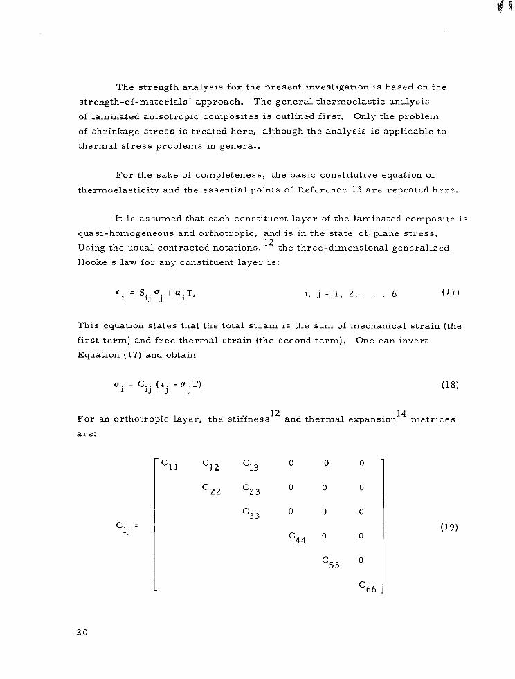
quasi-homogeneous and orthotropic, and is in the state of- plane stress.
Using the usual contracted notations, 12 the three-dimensional generalized
Hooke’s law for any constituent layer is:
C. = S.. 0. t aiT, i, j = 1, 2, . . . 6 (17) 1 iJ J
This equation states that the total strain is the sum of mechanical strain (the
first term) and free thermal strain (the second term). One can invert
Equation (17) and obtain
ai = Cij (c. - ajT) J
(18)
For an orthotropic layer, the stiffness 12
and thermal expansion 14
matrices
are:
‘ij =
c11 c12 c13 0
c22 ‘23 0
=33 0
c44
0 0
0 0
0 0
0 0 (19)
20

=1 I 0
0 0
a. =
1
a2 0 0
0 I a3
For a state of plane stress, it is assumed that:
“3 = u 4 = “5 =o
Substituting Equations (19), (20), and (21) into (18)s
‘4 = ‘5 = 0, and
c31 a T=-- ‘32 <3- 3 (f -
c33 l alT) - ~(6~ - a2T)
33
(21)
(22)
(23)
Substituting Equation (23) into (18),
= (Cl1 43
O1 - -1 (Cl c33
-alT) + (Cl2 - ‘13 ‘32
c33 ) (c2 - a2T) (24)
= (C21 - ‘23’13
a2 c33 1 (61 -alT) + (Cz2
c32 -- c33 )tc2 - a2T) (25)
O6 = ‘66’6
21

In terms of engineering constants, 15
= El/ h
2 ‘23
c22 - qy = E2’ x (27)
c12 - ‘13’23
c33 = V21El/X = V12E2/ h
where A = 1 - v12 v21
The equivalent constitutive equation for a laminated anisotropic com-
posite can be derived using the basic assumption of the nondeformable nor-
mals of the strength of materials. It is assumed that
t- = i t;+ ZK.
1 (28)
where, following the notations in Reference 2, i = 1, 2, and 6.
Equation (18), when integrated across the thickness of the laminated
composite, becomes:
TV. 1
= Ni+N;= Aij to+B.. K. J 1J J
ni = Mi+MT= B.. fo 1J J + Dij K’ J
(29)
(30)
22

where
r h/2
(I’$, Mi) = -h/2
“i (l, z,
(NT, MT) = s
h/2 -h/2
CijajT (
dz
‘, z) dz
(31)
(32)
r h/2 (33) (Aij, Bij, Dij) =
-h/2 Cij (1, z, z2) dz
Equations (29) and (30) are the basic constitutive equations for a lam-
inated anisotropic composite, taking into account equivalent thermal loadings.
The stress at any location across the thickness of the composite can
be determined as follows:2
I = Then, by ma :rix inversion,
I
cc
n
!
0 c
K
)
I I
A ! B
---;-- I
B ! D
=
A:: ; B:::
I _--m--m
=
(34)
(35)
(36)
23
-
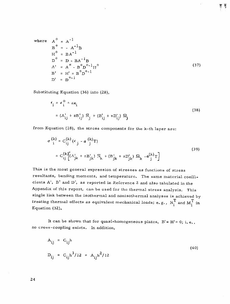
where A :;
= A-l
B* = - A-‘B
Hz: = BA-’ 9:
D’ = D - BA-‘B .,a A, = A-‘. _ B:::D::::-lH:::
B’ >‘< .1- = Hl = B eD-‘--l
D’ = D+-1
(37)
Substituting Equation (36) into (28),
6. = f” f ZK 1 i i
(38)
= (Aij f zBtj) mj t (Bij t zD4) Mj
from Equation (18), the stress components for the k-th layer are:
U lk) = C!k) (t _ a (k)T)
i iJ J j (39)
t zB! ) s t (B’ t zD! ) M Jk k jk
-a(k)T Jk k J I
This is the most general expression of stresses as functions of stress
resultants, bending moments, and temperature. The same material coeffi-
cients A’, B’ and D’, as reported in Reference 2 and also tabulated in the
Appendix of this report, can be used for the thermal stress analysis. This
single link between the isothermal and nonisothermal analyses is achieved by
treating thermal effects as equivalent mechanical loads; e. g., NT and MT in
Equation (32).
It can be shown that for quasi-homogeneous plates, B’= H’= 0; i. e.,
no cross-coupling exists. In addition,
Aij = ‘ijh (40)
Dij = Cijh3/‘2 = Aijh2/12
24
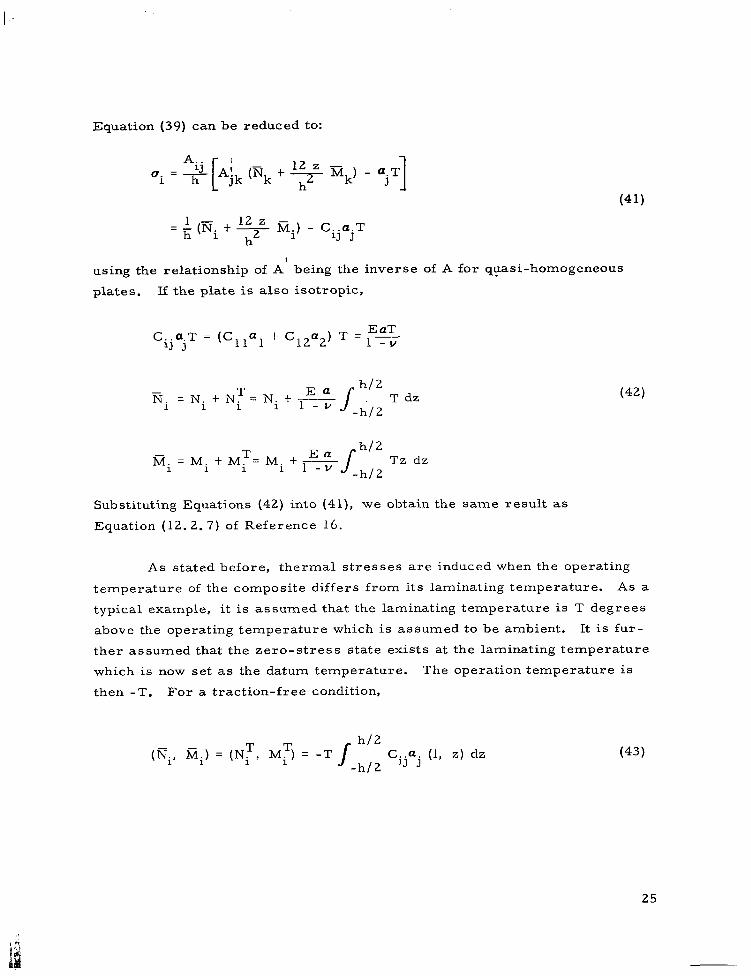
Equation (39) can be reduced to:
A.. ui = 2
h C Ajk (mk t
(41)
= ; (mi t = i%) - CijojT h2
using the relationship of A being the inverse of A for quasi-homogeneous
plates. If the plate is also isotropic,
CijQjT = (Cllcl t C12a2) T = f’“’ -v
fii =NitN;=Nit= h/2
1 -v s -h/2 T dz (42)
Mi = Mi t MT= Mi t = h/2
1 -v s Tz dz
-h/2
Substituting Equations (42) into (41), we obtain the same result as
Equation (12.2. 7) of Reference 16.
As stated before, thermal stresses are induced when the operating
temperature of the composite differs from its laminating temperature. As a
typical example, it is assumed that the laminating temperature is T degrees
above the operating temperature which is assumed to be ambient. It is fur-
ther assumed that the zero-stress state exists at the laminating temperature
which is now set as the datum temperature. The operation temperature is
then -T. For a traction-free condition,
(Ni, ik) = (NT, MT) = -T / h/2
-h/2 Cijaj (1, z) dz (43)
25

From Equation (39)
,,(k) = $4 i iJ
(Aik + zBik) N; + (Bik + ZDik) Ml + a(;) T] (44)
For an isotropic quasi-homogeneous plate under uniform temperature,
(45) Bik = 0, Cij = Aij / h
Substituting Equation (45) in (41) and.(38), one obtains, as expected
ui=LN?- h 1 ‘ijajT = O (46)
ci = AijNj = - aT
If the temperature is linear across the thickness of the isotropic
quasi-homogeneous plate; i. e.,
T = az (47)
then by substituting Equation (47) into (32), one obtains
NT = 0, MT = _ Ea ah3 12 (1 - v)
Hence, from Equations (41) and (38), one obtains, again as expected,
(T. =L l2 z 1 h h2
MT - CijajT = 0
E. = zD!.MT = - aaz 1 iJ J
(48)
(49)
The results of Equations (46) and (49) agree with the elementary theory; e.g.,
Equation (9.5.66) of Reference 16.
26
The strength analysis of a laminated anisotropic composite is accom-
plished by substituting the stress components of the k-th constituent layer,
calculated from Equation (39), into the general yield condition of Equation (8),
or its equivalent equation,‘ when 0 1 is equal to zero, e. g., Equation (13).
From Equation (8), the maximum u 1, in combination with the particular p and
q that each constituent layer can sustain, can be obtained. When this maxi-
mum is reached, failure in the particular layer or layers is considered to
have occurred. After this failure, the remaining layers, which have not
failed, will have to carry additional loads. This shifting of loads is accom-
panied by a partial or complete uncoupling of the mechanical and thermal
interactions mentioned above. The net result is that a new effective stiffness
of the laminated composite is now in operation. This new stiffness, as
reflected in new values of A, B, and D matrices of Equation (34), will cause
a change in the distribution of stresses in each of the constituent layers still
intact. The effective stress-strain relation of the composite is changed and
a “knee” is exhibited as the slope of the stress-strain relation becomes dis-
continuous. New values of A’, B’, and D’ matrices which are computed from
the revised A, B, and D, must now be used in Equation (39) for the computa-
tion of the stresses. These new stresses will again be substituted into the
yield condition of Equation (8), from which the next layer or layers that would
fail can be determined. This process is repeated until all the layers have
failed.
The mathematical description of the uncoupling of the mechanical and
thermal interactions is not easy to ascertain. As one possibility, cracks
transverse to the fibers will develop, which cause a degradation of the effec-
tive stiffness and a change in the stress distribution in the composite. Another
possibility is a complete delamination of the laminate, thereby uncoupling the
thermal and mechanical interactions. The exact description of the degradation
process must be treated for particular laminates, as will be shown later.
The important point intended for this section is to illustrate the exist-
ence of mechanical and thermal interactions as a direct consequence of lam-
ination. Internal stresses are induced. These stresses exist in addition to
27
the externally imposed stresses. Unlike the work of References 7 through 10,
the present investigation makes the necessary distinction between quasi-
homogeneous and laminated composites.
Cross-ply Composites
The general equations for the analysis of strength can be considerably
simplified if the laminated composite is a cross-ply composite, which con-
sists of constituent layers oriented alternately at 0 and 90 degrees. All odd
layers have one thickness. All even layers also have one thickness but are,
in general, different from the odd layers. The lamination parameters, fol-
lowing the notations of Reference 2, include the total number of layers, n,
and the cross-ply ratio, m, which is the ratio of the total thickness of the odd
layers over that of the even layers. For the present work, as in Reference 2,
the odd layers are oriented at 0 degree.
As an illustration of how the strength analysis may be carried out, a
particular case of n = 3, m = 0. 2 will be shown in detail. Only uniaxial ten-
sion will be considered, i. e., only N 1 is nonzero. Since the laminated com-
posite is symmetrical with respect to the centroidal axis by virtue of having
n = 3, and only symmetrical loading (i. e., all bending moments are zero) is
considered, the stress distribution in the first and third layers will be iden-
tical. Thus, only two layers have to be considered in the strength analysis:
the inner layer (layer 2) and the outer layer (layer 1 or 3). From Equa-
tion (39), for the outer layer,
0 ‘1l’ = C(111)(Ail~l t Ai2N2 -a I’) T) f C(IZZ)(A~lN, + A~2”2 -a~‘)T)
(1) = (‘11 Ai1 “12 21 (l) A’ ) Nl
(50)
_ ($) Q (1) + c(1) 11 1 12 a2) T 1
28
(1) (CzlAil+c22 21 (l)A’ ) (1) NT + (Czl Ai -t- Cy2)Ai2) Nr
0 (l) = 0 6
In the above, Equation (29) was used; i. e.,
for the inner layer,
(A;& -Q 12) T)
(52)
(53)
(54)
This equation, when expanded, will be the same as Equations (50) through
(52), except that superscript (1) will be replaced by superscript (2).
Using the following experimentally determined material properties
which represent typical unidirectional glass filament-epoxy resin compos- .L
ites, .,. one can evaluate the stress components for the inner and outer layers
in terms of the axial stress resultant N1 and the lamination temperature T.
“The same composite which was reported in Section 2.
29

II .11,1 II II I II m--II . II ,. ,. . . _.. . . . . ..--.-. ..-- -.. ,.__._.. --_- . -.- _.... ..___ -- .-..-. v Fl
$) = $2 =
11 7.97 x lo6 psi
C(l) = Cyi = 0.66 x lo6 psi 12
C(l) = Ct2) = 2 66 x lo6 psi 22 11 *
C(l) = Cfi = 1.25 x lo6 psi 66
$) = 16 ‘26
(1) = c’l”d = $2 = 0
ay = a I?“’ = 3.5 x 10⁻⁶/o=
a(l) = a i”’ = 2
11.4 x 10 470~ .,
,U) = a k”’ = 0
6
(55)
In, a three-layer (n = 3) and m = 0. 2 cross-ply composite, one can compute
the following quantities which are needed for substitution into Equations (50)
through (53). From Equations (33) and (37),”
*ii = 0.29 x 10 -61 in /lb .
Ai2 = -0.03 x 10 -6 in /lb .
A.;2 = 0.14 x 10 -6 in /lb .
(56)
-“The detailed calculation and some typical data for glass-epoxy composites are shown in the Appendix.
30

From Equation (32), assuming a constant lamination temperature T, one can
compute the equivalent thermal forces and moments:
NT= 33. 1 T lb-in.
N; = 35. 0 T lb-in.
Nz= MT= 0, as expected for three-layer cross-ply
(57)
Substituting the computed values in Equations (56) and (57) into the equations
for the stress components (50) through (55), for the outer layers,
u ‘1l’ = 2.27 N1 f 35. 5 T
u ;l’ = 0. 12 N1 - 16. 0 T
(1) = 0 O6
and for the inner layer,
u y’ = 0.75 N1 - 7.1 T
u r’ = 0.02 N1 -k 3.2 T
(58)
(59)
The yield condition governing the initial failure is determined in terms of the
maximum axial stress resultant N1 by substituting Equations (58) and (59) into
the general yield condition Equation (8) for 8 = 0 and 90 degrees, respectively.
31

Equation (8) for the case of q = 0 (zero shear) becomes, for 8 = 0 degree
(outer layer),
1 - p + p2r2 = (X/U,)~
(60) or +u 2 2=x2
l”2+’ u2
for 19 = 90 degrees (inner layer),
P2 -pfr’ = (x/u1)2
2 2 2 2 or r al-u1u2+u2=X
(61)
Using the following experimentally determined strength values which repre- :::
sent a typical unidirectional glass fi lament-epoxy resin composite,
Axial Strength = X = 150 ksi
Transverse Strength = Y = 4 ksi
Shear Strength = s = 6 ksi
(62)
from which, one obtains
r = X/Y = 37.5 (63)
s =X/S = 25.0
Substituting Equations (63) and (59) into (61), and solving the resulting quad-
ratic equation for N1, one obtains the stress resultant that causes failure in
the inner layer:
N1 - 9.6 T + 1.33 Y (64)
The same composite as reported in Section 2.
32

For a composite laminate at 270°F, or T = -200,
N1 = 3400 psi (65)
For that laminated at room temperature, or T = 0,
N1 = 5320 psi (66)
Similarly, substituting Equations (63) and (58) into (60), one obtains the stress
resultant that causes failure in the outer layer:
N1 = 110 T + (57. 5 Y2 - 3000 T2)1'2
For a composite laminated at 270°F, or T = -200,
N1 = 6300 psi (68)
For that laminated at room temperature, or T = 0,
(67)
N1 = 30,400 psi (69)
Comparing the results above, one can see that the inner layer will fail before
the outer layer. It is also shown that the first failure would occur at a higher
stress if the lamination temperature is ambient. From Equation (59) it can
be seen that an elevated lamination temperature (T = negative) causes a pre-
tension in U1 which is the normal stress transverse to the fibers. This will
reduce the maximum N1 at the “knee. ”
33

The effective stiffness of the laminated composite up to the “knee” is simply
the reciprocal of Ai1 (for unity thickness); i. e., from Equation (56) the effec-
tive stiffness is 3.4 x lo6 psi. Thus, the in-plane strain at the “knee” is,
using N1 = 3400 from Equation (65),
c; = 3400/3.4 x 10 6 = 0. 1% (70)
The behavior of the cross-ply composite after the “knee” depends on the
degree of uncoupling of the mechanical and thermal interactions. An imme-
diate possibility is that cracks transverse to the fibers are developed in the
inner layer. (2) This can be described by letting C22 of the inner layer remain
constant while the remaining components are “degraded” to a very small
fraction of their intact values, as listed in Equation (55). The resulting mate-
rial properties of this partially degraded composite (inner layer degraded)
become in place of Equation (56), (58) and (59),
Ail = 0.75 x 10 -6 in /lb .
Ai2 = 0.01 x 10 -61 in /lb . (71)
A;2 = 0.14 x 10 -6 in /lb .
u;” = 6. 00 N1
(72) u;‘) = 0.47 N1 - 19.3 T
V)= 0 a6
and
J2) = 1
u(2) = 0 6 (73)
J2) = 2 -0. 09 N1 t 3. 9 T
34
Note that the thermal coupling in the l-direction is reduced to zero. But the
thermal coupling in the 2-direction, as shown in Equation (72), is increased
after the degradation. In fact, the increase is so high (equal to 19. 3 T) that
the outer layers cannot remain intact after the initial degradation. What this
means is that the outer layers will also degrade immediately, thus causing a
complete uncoupling between the layers. Thereafter, only the uncoupled outer
layers can carry the load. One can easily solve for the axial load that a par-
tially degraded cross-ply can carry by substituting the stress components of
Equation (72), into the yield condition of Equation (60). The maximum N1
turns out to be considerably lower than the existing stress of 3400 psi.
After two successive failures, which occur almost simultaneously, the
laminated composite becomes completely uncoupled both mechanically and
thermally. Actual separation among constituent layers has been observed. In
order to characterize this completely degraded composite, it is assumed that
only the stiffness parallel to the fibers remain; i. e., C (1) (2) 11 and C22 are the
only nonzero components. (I n order to avoid computational difficulties in the
matrix inversion, the other components are assumed to be vanishingly small
but not zero. ) The resulting material properties of this completely degraded
composite become in place of Equations (56), (58) and (59),
Aii = 0.77 x 10 -6 in /lb .
A;2 = 0
A22 = 0.15x10 -6 in /lb .
The only nonzero stress components due to N1 is:
(74)
a;‘) = 6. 00 N1 (75)
35
Thus, the effective stiffness of the composite after the “knee” is
l/hAi 1 = 1.3 x lo6 psi. The ultimate strength can be computed as follows.
The stress in the outer layers immediately before the degradation of the inner
layer is computed from Equation (58) using N1 = 3400 and T = -200,
,w = 1 618 psi 2 600 psi (76)
Since the maximum stress u (1) 1 can reach is equal to the axial strength,
150, 000 psi, the outer layers can be stressed an additional amount of
150, 000 - 600 = 149,400 psi. Using Equation (75), this additional stress
beyond the “knee” represents a stress resultant of 149, 400/6. 00 = 24, 900 psi.
Then the ultimate stress resultant Nl is the sum of 24, 900 and 3, 400, which
is 28, 300 psi. The experimental measurement of the effective stress-strain
relation of a three-layer cross-ply composite is shown in Figure 5. The
agreement with the theoretical prediction is excellent for this case.
It can be stated that a “knee” does exist and its existence can be ex-
plained in terms of the uncoupling of the mechanical and thermal interactions. . If the lamination temperature is ambient, then the “knee” would occur, from
Equation (66), at N1 equal to 5320 psi, instead of 3400 psi. The resultant
ultimate strength of the composite, however, turns out to be practically the
same as that laminated at 270°F.
The conventional netting analysis predicts the following stiffness and
strength, based on two-thirds of glass by volume, with glass stiffness and
strength of 10. 6 x lo6 psi and 400, 000 psi, respectively,
E11 = 10.6 x lo6 x 2/3 x 2/12 = 1. 18 x lo6 psi
(77)
Ol = 400, 000 x 213 x 2112 = 44, 000 psi
These data are also shown in Figure 5. It is interesting to note that the
measured strength is only 68 percent of that predicted by netting analysis.
36
40
30
- z hi
d-c z I 20
10
c
EXPERIMENT
NETTING ANALYSIS
ODENOTES ULTIMATE FAILURE
0 1.0 2.0 3.0 4.0
61”l (PERCENT)
Figure 5. Strength of o Typical Cross-Ply Composite
37

For the purpose of more extensive experimental confirmation, three-
layer cross-ply composites with different cross-ply ratios were made and
tested. The theoretical predictions and the experimental results for both the
effective initial and final stiffnesses (before and after the “knee, ” respec-
tively), and the stress levels at the “knee” and the ultimate load are shown in
Figure 6. It is fair to state that the present theory is reasonably confirmed
experimentally. The scatter of data can be traced partly to the difficulty in
making cross-ply tensile specimens. In the process of shaping the specimens
by a router, the layer oriented transversely to the axis of the dog-bone
specimens is often damaged.
The present theory involves lengthy arithmetic operations. Part of
this burden can be relieved by using the tables listed in the Appendix. The
input data are those listed in Equation (55). The composite moduli and the
equations for the stress components and the thermal forces and moments are
computed for two- and three-layer composites with cross-ply ratios varying .b
from 0.2 to 4. 0. -. For each cross-ply composite, two cases will be listed:
Case 1 represents all layers intact; and Case 2, all layers completely
“degraded. ” With the aid of these tables, the data as shown in Equations (56)
through (59), and (74) and (75) can be read directly.
In order to demonstrate the existence of thermal forces and moments,
a two-layer cross-ply with two equal constituent layers (m = 1) was laminated
at 270°F. At temperatures lower than the lamination temperature, the lami-
nated plate becomes a saddle-shaped surface. For a square plate with
length R, thickness h, clamped at one edge (y = 0), as shown in Figure 7,
:‘: ‘AS shown in Reference 2, two- and three-layer laminated composites
represent two extreme cases, with all composites having larger numbers of layers falling in between the extremes.
38
-
Ii/r-I ‘FINAL STIFF,NESS ( I I I
+ -CROSS-PL\! .-77-j
BOW-1 I \ d 7
60 - -- / ~
40 yy: i-
._c- --
STRESS AT “KNEE” -I-
20
I I II I ii 111 t I I I I I
I 1
0 +a I $A ~-+-+
0.2 0.3 0.4 0.5 0.7 1.0 2.0 3.0 4.0 5.0
CROSS-PLY RATIO (IN.)
Figure 6. Strength of Cross-Ply Composites 39
I I
-100 0
-0.2
-0.4
wep IN INCHES
T IN OF
b -100
-0.2
-0.4
TINOF
Figure 7. Thermal Warping of a Two-Layer Composite
the deflected surface due to homogeneous stress resultants and bending
moments can be shown to be a quadratic surface,
1 21 21 w = z K1 x + z K2y + z K6xy -k ax + by + c (78)
Where kappas are the curvatures, constants a, b, c are determined from
boundary conditions, as follows:
(1) Whenx=y=O, w=O
(2) When x = 1, y = 0, w = 0 (79)
&Lo (3) When y = 0, dy
From the above, the displacements at the midpoint (x =,L?/2, y =,l?,) and the end-
point (x = y = a) as shown in Figure 7 are:
5 2 w = mp 8 KR
(80) 1 w = cl2
ep z Kd
where K 6 = 0, and K = K1 = -K2. (The last equality is true by virtue of the
cross-ply ratio being one. )
Since the warping of the laminated composite is caused by the thermal
coupling with no externally imposed loads, one can apply the basic material
properties in Equation (55) to Equation (43), and obtain .
T N1
T = N2 = 34. 0 hT
(81) T T 2 Ml = -M2 = -0.36 h T
41
IL:

Substituting these thermal forces and moments into Equation (36), one can
establish the curvature
K1 T = BilNl + (Dil
T - Di2) Ml
0.35 10 -6 x = x 34. 0 hT (2. 84 + 0. 35) x 10 -6 -
h2 h3 x 0.36 h2T
(82)
= 10.75 x 10 -6 T/h
For the particular test specimen, width L? = 8. 5 inches and thickness
h = 0. 18 inch; by substituting these data into Equation (80), one finds
W = 0. 0027 T mP
(83)
W = 0. 0022 T ep
In Figure 7, Equation (83) and appropriate experimental measurements are
shown. A good agreement between theory and experiment is seen. This fur-
ther substantiates the effect of the thermal coupling as a direct result of
lamination.
In this section, the analysis of strength of cross-ply composites is
shown. The effect of thermal and mechanical coupling is outlined. It is seen
that the effective stress-strain relation has a “knee” resulting from the degra-
dation of the constituent layers. After the “knee, ” the laminated composite
becomes thermally and mechanically uncoupled but can carry an additional
load before the ultimate strength is reached. A method is outlined in this
section whereby the entire behavior of the cross-ply composite can be deter-
mined. Although the method and the experimental confirmation are limited to
uniaxial tension, the method can be extended to more general types of loading,
in terms of all six stress resultants and bending moments and arbitrary tem-
perature, in a straightforward manner. This will be described further in
Section 4.
42
_.... -. .._ ..---.-.. - ._.._ -.- --.. _ - _ .-
Angle-ply Composites
The angle-ply composite consists of n constituent layers of an ortho-
tropic material, as represented by a quasi-homogeneous unidirectional com-
posite, with alternating angles of orientation between layers. The odd layers
are oriented with an angle - 0 f rom the l-axis of the reference coordinate, and
the even layers, +e. All layers have the ‘same thickness. The lamination
parameters for the angle-ply composite, as in Reference 2, are the total num-
ber of layers n, and the lamination angle 8.
The effective stiffnesses of angle-ply composites made of glass fila-
ment and epoxy resin were accurately predicted by using the strength-of-
materials approach. 2 Using those stiffnesses, one can obtain the stress dis-
tribution in each constituent layer from Equation (39) as functions of stress
resultants, bending moments, and lamination temperature. Similar to the
method described for the cross-ply, the general yield condition of Equa-
tion (8), can then be applied to each layer. The ultimate strength of the angle-
ply can then be calculated. In the case of the angle-ply under uniaxial tension,
unlike the cross-ply, there is no “knee” in the effective stress-strain relation.
This is explained by the fact that after the layers with positive or negative
orientation have failed, the remaining layers alone, although still intact, can-
not carry the existing load. Thus, failure of the entire laminated composite
occurs immediately after the initial failure of the positively or negatively
oriented layers. This is a peculiar behavior of angle-ply composites under
uniaxial loading.
Since the strength analysis of angle-ply composites requires the knowl-
edge of the coordinate transformation and its effect on material properties
and stress components, the standard coordinate transformation is repeated
here and its relevance to angle-ply composites is indicated.
43
-’
There are positive and negative rotations for coordinate transforma-
tion about the z-axis; they are represented symbolically by:
or graphically:
Y’ Y
X'
ILL e
X
Equation (6) and Figure 2 correspond to the positive rotation Tf. The x-y
coordinates represent the original axes, and xl-y’ the transformed axes.
Since all odd layers of an angle-ply composite are oriented with a negative
angle, the necessary transformation of the mechanical and thermal properties
of this system of layers into the reference coordinates 1-2 requires a positive
rotation T +
; conversely, all even layers where the orientation is positive re-
quires a negative rotation T-.
44
I -
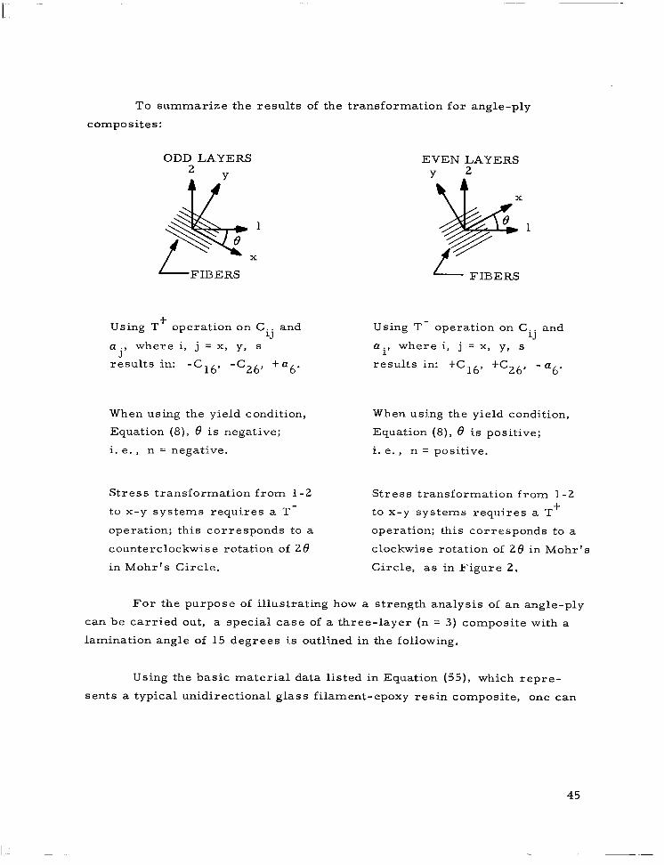
To summarize the results of the transformation for angle-ply
composites:
ODD LA.YERS EVEN LAYERS 2 Y 2
Using T’ operation on Cij and
a ., 3
where i, j = x, y, s
results in: -C 16’ -c2& +a6.
Using T- operation on Cij and
a i’ where i, j = x, y, s
results in: tC 16’ +c26’ -n6.
When using the yield condition, When using the yield condition,
Equation (8), 8 is negative; Equation (8), 8 is positive;
i. e., n = negative. i. e., n = positive.
Stress transformation from l-2
to x-y systems requires a T-
operation; this corresponds to a
counterclockwise rotation of 28
in Mohr’s Circle.
Stress transformation from l-2
to x-y systems requires a T +
operation; this corresponds to a
clockwise rotation of 26 in Mohr’s
Circle, as in Figure 2.
For the purpose of illustrating how a strength analysis of an angle-ply
can be carried out, a special case of a three-layer (n = 3) composite with a
lamination angle of 15 degrees is outlined in the following.
Using the basic material data listed in Equation (55), which repre-
sents a typical unidirectional glass filament-epoxy resin composite, one can
45
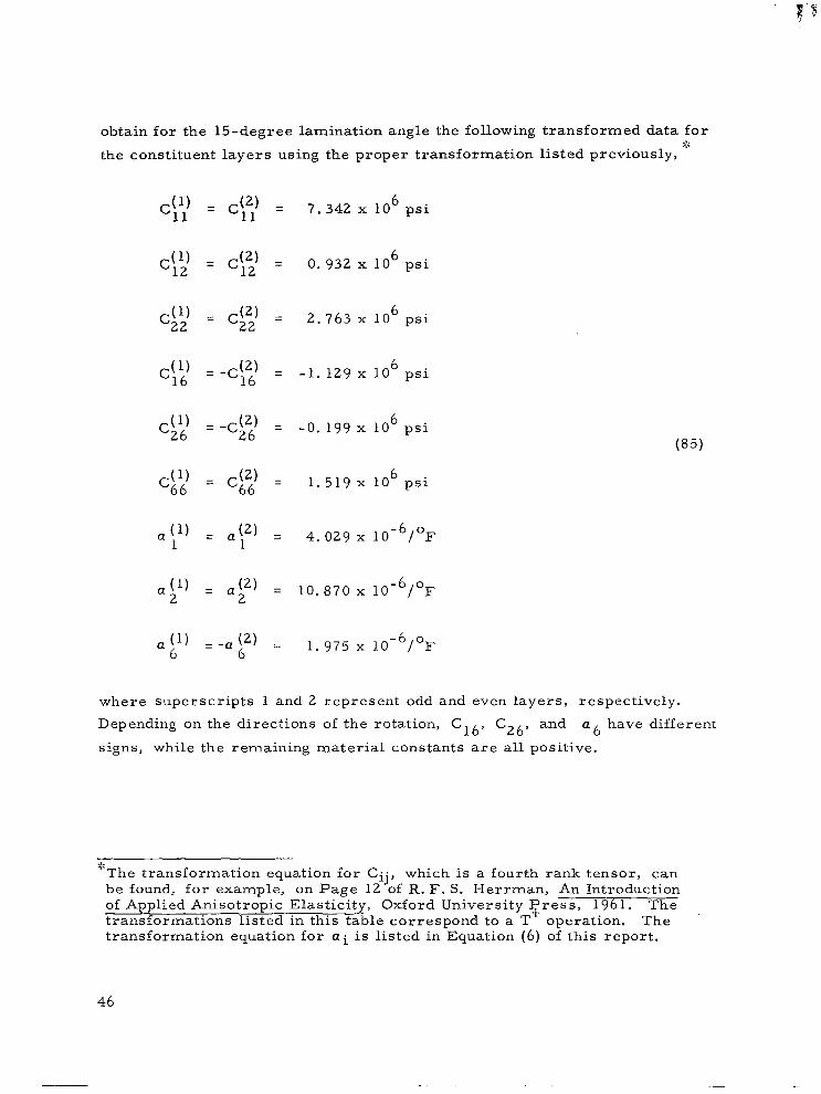
obtain for the 15-degree lamination angle the following transformed data for :::
the constituent layers using the proper transformation listed previously,
c(l) 11
$) 12
(1’ c22
C$’
C$)’
Cg
Q (1) 1
a (1’ 2
ap
= ($2) = 11
= (32) = 12
= (32) = 22
= -&2’ = 16
= (52) = 66
= a (2) = 1
= a (2) = 2
1 -a (2) = 6
7.342 x 10⁶ psi
0.932 x 10 6 psi
2.763 x 10 6 psi
-1. 129 x lo6 psi
-0.199 x 10⁶ psi
1.519 x 10 6 psi
4. 029 x lo-‘/OF
10.870 x lo-‘/OF
1. 975 x lo-‘/OF
(85)
where superscripts 1 and 2 represent odd and even layers, respectively.
Depending on the directions of the rotation, C16, C26, and a6 have different
signs, while the remaining material constants are all positive.
9; ‘The transformation equation for Cij, which is a fourth rank tensor, can be found, for example, on Page 12 of R. F. S. Herrman, An Introduction of Applied A.nisotropic Elasticity, Oxford University Press, 1961. The transformations listed in this table correspond to a T operation. The transformation equation for a i is listed in Equation (6) of this report.
46
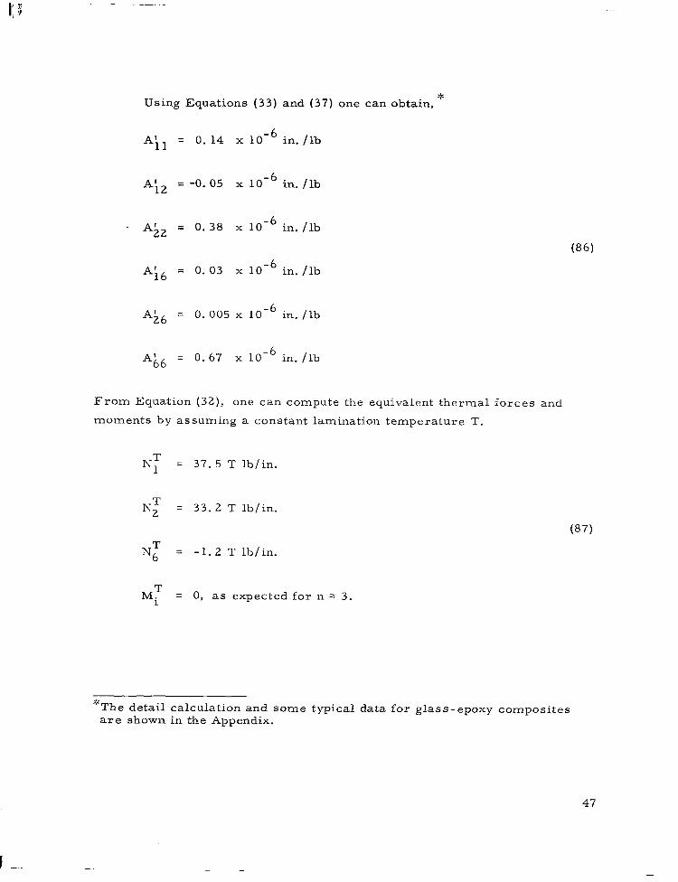
Using Equations (33) and (37) one can obtain, ”
Aii = 0.14 x 10 -61 in /lb .
Ai2 =-0.05 x 10 -6 in. /lb
. Ai = 0.38 x 10 -6 in. /lb
(86)
A,i6 =0.03x10 . -6 in /lb
A;6 = 0.005x10 -6 in /lb .
Ak6 = 0.67 x 10 -6 in /lb .
From Equation (32), one can compute the equivalent thermal forces and
moments by assuming a constant lamination temperature T.
T Nl = 37. 5 T lb/in.
T N2 = 33. 2 T lb/in.
(87)
NT = -1. 2 T lb/in.
MT = 0, as expected for n = 3.
“The detail calculation and some typical data for glass-epoxy composites are shown in the Appendix.
47

Substituting the values in Equations (85) and (87) into Equation (39) and letting
N1 be the only nonzero load, one obtains,
,U) = 1 0.97 N1 - 0.44 T
*(l) = 2
- 0.08 T
Jl) = 6
-0. 10 Nl - 1.79 T ’
and
(2) = al
1.05 Nl + 0.89 T
(2) = a2
0. 01 Nl t 0. 16 T
(88)
(89)
(2) = a6
0.20 Nl t 3. 58 T ”
The yield condition of Equation (8) can be considerably simplified for this
particular angle-ply by letting p = 0 because the a2 in both Equations (88)
and (89) is small in comparison with u6. Also using the strength values
listed in Equations (62) and (63), one obtained a simplified form for Equa-
tion (8) as
A 0; t B ol c6 t C 0; = x2
where
A = m t 624 m2n2 t 1406 n4 4
B = - (1244 m3n f 4386 mn3)
C = 625 m4 t 4382 m2n2 t 625 n4
(90)
“These shear stresses can properly be designated as the interlaminar shear stresses which are induced by axial stress resultant N1 and lamination temperature T. The common usage of the interlaminar shear in the filament winding industry referring to a particular test method is entirely different from the shear stresses above.
48
For 8 = -15O (this applies to the odd layers),
A = 46. 20, B = 363.91, C = 821. 00 (91)
For 8 = t15O (this applies to the even layers),
A = 46. 20, B = -363.91, C = 821. 00 (92)
Substituting Equations (91) and (88) into (90), one can solve for the maximum
Nl for the outer layers,
16. 12 Nf - 359. 3 Nl T t 2938 T2 - x2 = 0
or
Nl = 11. 14 T t 37,400
(93)
(94)
For a lamination temperature at 270°F, T = -200°F,
Nl = 35,200 psi (95)
Similarly, substituting Equations (92) and (89) into (90), one can solve for the
maximum N 1 for the inner layers,
7.52 Nf - 148. 3 Nl T t 9429 T2 - x2 = 0 (96)
Nl = 9. 87 T t 54, 600
for T = -200,
Nl = 52, 600 psi (97)
Thus, the outer layers will fail first for having a lower Nl, and in fact, the
ultimate load of this composite will be 35, 200 psi because the inner layer
cannot carry the load alone after the outer layers have failed.
49
,
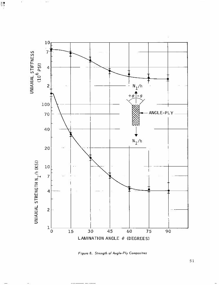
Similar calculations, as described from Equations (93) through (97),
are repeated for other lamination angles and the theoretical predictions
together with the measured data are shown in Figure 8. Also included in
Figure 8 is the initial effective stiffness of the angle-ply composite. For
both the strength and the stiffness, excellent agreement exists between the
theory and experimental observation. For intermediate lamination angles,
nonlinear stress-strain relation is observed. The actual ultimate strain at
the failure stress is about 2 to 3 times larger than that computed from the
tangent modulus . It is interesting to compare the strength of unidirectional
composites, as shown in Figure 4, with the angle-ply, in Figure 8. up to
45 degrees, the angle-ply has up to 50 percent higher strength than the uni-
directional. For angles larger than 45 degrees, the angle-ply becomes
weaker than the unidirectional. These differences in strength can be traced
directly to the mechanical and thermal interactions, because of the non-
vanishing Cl6 and C26, and T, respectively.
ln order to facilitate the strength analysis of glass-epoxy angle-ply
composites, composite moduli and coefficients for stress components are
listed in the Appendix for n = 2 and 3 and 8 = 5, 10, 15, 30, 45, 60, and
75 degrees.
In conclusion, a method for determining the strength of angle-ply
composites has been formulated. This method can be extended to the most
complicated types of loading with all six components of stress resultants and
bending moments and arbitrary temperature distribution across the thickness
of the composite. Differing from the case of cross-ply composites, the
angle-ply cannot carry additional uniaxial load after failure has initiated in
one system of layers. Consequently, no discontinuity in the slope of the
effective stress-strain relation is predicted by the present strength analysis,
nor observed experimentally. For this reason, no subsequent degradation of
the constituent layers has been investigated.
50
100
70
40
20
10
7
4
2
1
i
\ 7
.-
ANGLE-PLY ~
1 Nl/h
0 15 30 45 60 75 90
LAMINATION ANGLE e (DEGREES)
Figure 8. Strength of Angle-Ply Composites
51


SECTION 4
CONCLUSIONS
The present report outlines a method of strength analysis for both
quasi-homogeneous and laminated composites. This method requires the
experimental determination of some basic material properties, like those
listed in Equations (55) and (62). As stated in the Introduction (Section l), a
clear distinction is made between the structures and materials research on
composite materials. The present report only covers the structures aspect
of strength. The materials aspect, on the other hand, is to be investigated
in the future.
It is important to recognize two aspects of the results of the present
investigation: (1) the strength of a nonisotropic material requires three
strength characteristics, X, Y, and S; (2) for fiber-reinforced composites
such as the glass-epoxy composite, the strength values thus far must be
experimentally determined. Even the case of the axial strength X cannot be
predicted from the constituent properties; e. g., the fiber strength and volume
ratio, with confidence. The fundamental data of X being 150 ksi for unidirec-
tional glass-epoxy composites, together with Y and S listed in Equation (62),
has been shown to be significant in the transformation of strength of a quasi-
homogeneous composite (Figure 4), and the strength characteristics of
cross-ply and angle-ply composites (Figures 6 and 8, respectively). Insofar
as the structures aspect of strength is concerned, it is more important to
know the correct value of the axial strength of 150 ksi than to be obsessed by
the apparent loss of the theoretical strength. The latter strength, based on
netting analysis, is predicted by using the virgin strength of glass (400 ksi)
corrected by its volume ratio (66 percent), the result being 266 ksi. What-
ever the reason or reasons for the loss of the theoretical strength may be, it
53
is more important to recognize that only a strength of 150 ksi has been real-
ized under a highly idealized condition, such as the test method used for the
present program; in all probability a greater loss of strength will exist in
actual structures. Since the application of composite materials is primarily
in structures, it is more significant to know what one has at his disposal
(that X = 150 ksi) than what he does not have (that X should have been 266 ksi).
The present investigation also shows the importance of the transverse
and shear strengths, Y and S, respectively. So long as structures are, in
general, subjected to more complex loading than uniaxial, loaded along the
fiber axis, Y and S should be treated with equal respect as the axial strength
X. In fact, the relatively low value of the transverse strength is directly
responsible for the “knee ” in the cross-ply composite, the presence of which
is detrimental to the structure for being less stiff for load beyond the “knee”
and for being porous resulting from cracks transverse to the fibers. Thus,
the improvement of fiber-reinforced composites may very well depend more
on the upgrading of the transverse and shear strengths than the axial strength.
The method of strength analysis outlined in this report can be general-
ized to loadings other than uniaxial tension. The coefficients for the stress
components in terms of all the stress resultants and bending moments, to-
gether with the lamination temperature, are listed in the Appendix for typical
glass-epoxy composites. For any given combination of N., Mi, and T, one 1 can determine the stress components within each constituent layer. One can
go to the tables in the Appendix and obtain directly the coefficients for each
Ni and Mi and T, derived from the expanded form of Equation (39). The
effects of thermal forces NT and thermal moments MT are lumped in the
“coefficients of temperature. ”
There are numerous limitations to the present theory of strength, the
most important ones are listed as follows:
(1) It is assumed that the tensile and compressive stiff-
nesses and strengths are equal. The present theory
can be modified to take into account different tensile
and compressive properties by following, for
example, the method described in References 6 and 7.
54

(2) The composite material is assumed to be linear
elastic up to the ultimate failure. For glass - epoxy
composites, this assumption has been found to be
reasonable with the exception of the unidirectional
and angle-ply composites with intermediate angles
of fiber orientations, say between 30 and 60 degrees.
(3) In the case of cross-ply composites, the piece-wise
linear stress-strain relation is intended to describe
the loading condition only. The behavior of the lam-
inated composite during unloading and reloading has
not been investigated.
(4) The degradation of angle-ply composites because of
cracks transverse to the fibers has not been investi-
gated. It is quite conceivable that the composite can
carry additional load after initial degradation under
more complex loading such as the biaxial stress.
Recommendations for future work include the following:
(a) The contribution of the constituents’ properties to
the basic strength characteristics X, Y, and S. This
will provide a basis to establish guidelines for the
rational design of composite materials.
(b) More extensive experimental verification of the
strength of unidirectional and laminated composites
under loading conditions other than uniaxial tension.
The test materials should include other combinations
of constituents than glass-epoxy.
(c) The present framework of research (combined struc-
tures and materials research) should be extended to
include crit.ical problems of nonelastic behavior,
creep, and fatigue of composite materials.
55
It is believed that, with the foregoing information of the strength
characteristics of composite materials, an improvement has been made in
the basic understanding of the structural behavior of composites. This added
knowledge will provide a better basis of design and utilization of composites.
It is hoped that additional researchers with interests in structures and mate-
rials will begin to contribute to this new area of research. With rapidly
advancing technology of new constituent materials and manufacturing proc-
esses, a rational basis of materials design is urgently needed. This report
may be considered as a typical example of the work still remaining in the
field of composite materials.
56
REFERENCES
1. Tsai, S. W. and D. F. Adams, “Combining Materials and Structures Research on Composite Materials, ” presented at the AIAA Sixth Struc- tures and Materials Conference, April 1965, In Press.
2. Tsai, S. W., “Structural Behavior of Composite Materials, ” NASA Report CR -71, July 1964.
3. Azzi, V. D. and S. W. Tsai, “Elastic Moduli of Laminated Anisotropic Composites, ” presented at the Annual Meeting, Society for Experimental Stress Analysis, October 1964, In Press.
4. Hill, R. , “A Theory of the Yielding and Plastic Flow of Anisotropic Metals, ” Proceedings of the Royal Society, Series A, Vol. 193, pp. 281-297, 1948.
5. Hill, R. , The Mathematical Theory of Plasticity, Oxford University ___~-- ~- Press, London, 1950.
6. Marin, J., “Theories of Strength for Combined Stresses and Noniso- tropic Materials, ” Journal of the Aeronautical Sciences, Vol. 24, No. 4, pp. 265-269, 274, April 1957.
7. Norris, C. B., “Strength of Orthotropic Materials Subjected to Com- bined Stress, ” Forest Product Laboratory Report 1816, 1962.
8. Werren, F. and C. B. Norris, “Directional Properties of Glass-Fiber- Base Plastic Laminate Panels of Sizes That Do Not Buckle, ” Forest Products Laboratory Report 1803, 1956.
9. Erickson, E. C. 0. and C. B. Norris, “Tensile Properties of Glass- Fabric Laminates with Laminations Oriented in Any Way, ” Forest Products Laboratory Report 1853, 1960.
10. Ashkenazi, E. K., “On the Problem of Strength Anisotropy of Construc- tion Materials, ” Soviet Physics - Technical Physics, Vol. 4, No. 3, pp. 333-338, September 1959.
11. Azzi, V. D. and S. W. Tsai, “Anisotropic Strength of Composites, I’ presented at the Spring Meeting, Society for Experimental Stress Analysis, May 1965, In Press.
12. Sokolnikoff, I. S., Mathematical Theory of Elasticity, Second Edition, McGraw-Hill Book Company, New York, 1956.
57
I

REFERENCES (Continued)
13. Tsai, S. W. and V. D. Azzi, “The Strength of Laminated Anisotropic Composites, ” presented at the AIAA 2nd A.erospace Sciences Meeting, Paper No. 65-75, January, 1965.
14. Carslaw, H. S. and J. C. Jaeger, Conduction of Heat in Solids, Second Edition, Oxford University Press, London, 1959.
15. Lekhnitskii, S. G., Anisotropic Plates, Second Edition, (In Russian), Gostekhidat, Moscow, 1957.
16. Boley, B. A. and J. H. Weiner, Theory of Thermal Stresses, Wiley, New York, 1960.
58
APPENDIX
MATERIAL COEFFICIENTS OF GLASS-EPOXY COMPOSITES
The purpose of this Appendix is to show the method of stress analysis
of a laminated composite, and to list material coefficients of a typical glass-
epoxy composite. The coefficients are intended to reduce the burden of com-
putation in the analyses of stress, strain, and strength. Since most mathe-
matical relations required for the present work have already been covered in
this report, they will only be cited by their equation numbers here in the
Appendix.
In a laminated composite, the variables of interests are, under the
strength-of-materials approach, the stress resultants N, bending moments
M, in-plane strains c 0 and curvatures K. In place of the stress-strain
relation, these four quantities are linked by relations shown in Equations (34),
(35), and (36). (Thermal forces and moments are automatically included
here. ) As mentioned in Reference 2, a laminated composite is described by,
at most, 18 independent elastic moduli, six each in the A, B, and D matrices,
which reduce to two independent moduli for quasi-homogeneous isotropic
material. Thus, knowing the 18 moduli for a given laminated composite, one
can solve for two of the unknown variables if the other t\-;o are given. In gen-
eral, N and M are given, then using Equation (36) and A’, B’ and D’ matrices,
one can find the in-plane strain and curvature. In special cases, such as a
pressurized cylindrical shell, in addition to the known stress resultants which
are the membrane stresses, the curvature by virtue of symmetry must be
zero. Thus, Equation (35) is the appropriate relation. Figure 17 in Refer-
ence 2, for example, reflects the use of A+, B’::, and H’:: and D+ matrices.
59

The stress in each layer is determined from knowing the in-plane
strain and curvature for a laminated composite and the stiffness matrix Cij of
the particular layer. Equations (38) and (39) show the precise relations. As
governed by the original assumption of the nondeformable normals, the strain
is linear, and the stress, piece-wise linear, across the thickness of the lam-
inated composite.
Unfortunately the computation of the A, B, and D matrices and their
inversions is difficult for hand computation. The stress equation, such as
Equation (39), involves not only the prime matrices A’, B’ and D’, but also
much arithmetic operation. A digital program has been prepared to compute
the following quantities for a general laminated composite:
(1) Composite moduli A, B, D, A:::, B:::, Hz::, D:::, A’, B’,
and D’.
(2) Thermal forces and moments per Equation (32) for a
constant temperature T across the laminated composite.
(3) Coefficients for each N., 1 Mi, and T in the stress rela-
tion, Equation (39). Since temperature is assumed to be
constant, the contributions of NT and MT and UT to the
stress component are lumped into one term designated
as “the coefficients of temperature. ”
The coefficients at the top and bottom of each constituent layer are
shown. The stress at any location within a layer can be obtained by a simple
linear interpolation.
The information just described is computed and tabulated for typical
glass-epoxy cross-ply and angle-ply composites. Also included is the
degraded case of cross-ply composites. The exact nature of the degradation,
as explained in the Subsection entitled Cross-ply Composites, consists of
having cracks developed transverse to the fibers in all constituent layers.
60
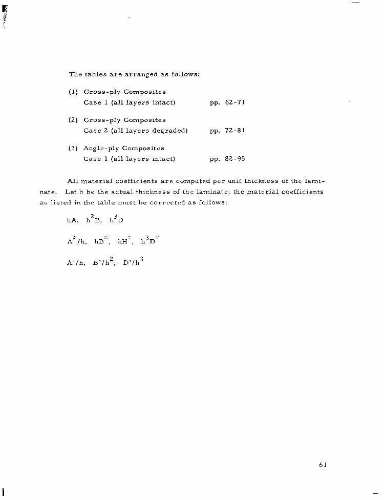
The tables are arranged as follows:
(1) Cross-ply Composites
Case 1 (all layers intact) pp. 62-71
(2) Cross-ply Composites
Case 2 (all layers degraded) pp. 72-81
(3) Angle-ply Composites
Case 1 (all layers intact) pp. 82-95
All material coefficients are computed per unit thickness of the lami-
nate. Let h be the actual thickness of the laminate; the material coefficients
as listed in the table must be corrected as follows:
hA, h2B, h3D
Al/h, B’/h2, D’/h3
61
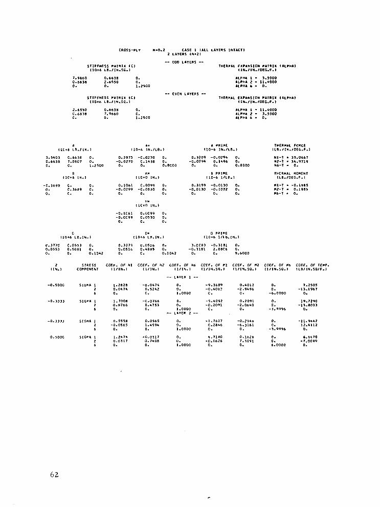
CROSS-PLY N.0.2 ClSE 1 ,ALL LA”E”S ,NT.CT, 2 LA”Ell5 (N-2,
STlFFNESS PA,RlX IC, I1016 LI.IlN.SC.1
7.9660 0.6638 0. 0.6630 2.6550 0. 0. 0. 1.2500
STIFFNESS *A,R,X IC, I1016 LB./lN.S9.l
ALPH. 1 - 3.5000 ALPHA 2 - 11.4000 ALPH. b - 0.
-- EVEN LAIERS -- THERPlL EXPlkSlOH CAT”ll (ALPHA,
IlN.flN.fOEC.F.l
2.6530 0.6630 0. ALPHA 1 - 11.5000 C.6638 7.9660 0. ALPHA 2 - 3.5000 0. 0. 1.25CO UPHA 6 . 0.
A A. A PP.lPE THEINAL FORCE ,,c*e LB./IN. I 110-b lN.,LB., 110-b IN-/LB. I ILB.IIN./OEG.F.l
3.5403 C.6638 0. 0.6638 1.0807 0. 0. c. 1.2500
0.2875 -0.0270 0. 0.3209 -0.0294 0. Nl-I = 33.0667 -0.0270 O.L438 0. -0.0294 0.1596 0. 112-T = 3*.97,9
0. 0. o.Bcoo 0. 0. 0.8000 Nb-1 - 0.
R. 8 PRIME ThER”AL YO”EN, IlO+O 14.1 110-b llle. I IL0.fOEG.F.I
e 11C16 IN.1
-c!.3689 c. 0. 0. C.3689 0. 0. c. 0.
c 1,016 Le.lk. I
c.3770 C.0553 0. 0.055, 0.5081 0. 0. 0. 0.10~2
I SrRESS COEF. OF Nl IlY.1 COWCNENI llllN.1
-0.5000 SIGCA 1 2 6
,.21)2(1 0.0574 0.
-0.3333 SIGPA l 1.7001 2 0.0766 b 0.
-0.3333 SlWA 1 2 6
0.5ooc SlGPA l 2 6
-- 000 LAIERS -- THERP.L EXPANSION FlTlll IALPMAI
IlN./lN./DEG.F.I
0.106, 0.0099 0. -0.co99 -0.05JO 0.
0. 0. 0.
H. IlC+O IN.1
-0.lC61 O.OCPP 0. -O.CCPP C.0530 0.
0. c. 0.
0* 0 PAlWE 110.6 LR.1N.j 110-b lILB.lN.l
0.33lE C.0516 0. ,.OCB, -0.3111 0. 0.0516 C.4885 0. -0.3181 2.0806 0. 0. C. O.lOS2 0. 0. 9.6000
0.5558 -0.05L5
0.
1.2476 O.OJlI 0.
0.3159 -0.0130 0.
-r,~Ol,O -0.1072 0. 0. 0.
CCEF. OF Y2 COEF. OF Nb COEF. OF Pl ll1lN.1 1lIlN.I 1111N.50.1
-- LAYER 1 --
-0.0174 0. -9.3689 0.5242 0. -0.501’ 0. ,.oooo c.
-0.0766 0. -5.5092 0.4753 0. -0.2091 0. 1.0000 C.
-- LA”EII 2 --
0.0565 0. -1.7617 L.4594 0. C.2846 0. 1 .oooo 0.
-0.0317 0. 4.1100 0.7408 0. -0.lbZb 0. 1.0000 0.
Ml-l - -0.1905 *2-r = 0.19.55 Mb-1 = 0.
COEF. OF *2 COCF. OF PL COEF. OF ,EW. ll11’(.5P.I Il/lN.SO.I ILB,lN.SC/F.I
0.4012 0. 7.2505 -2.9496 0. -13.1967
0. -6.0000 0.
0.2091 0. 19.2290 -2.0640 0. -13.8033
0. -1.9996 0.
4.2946 0. -b.3161 0.
0. -1.9996
0.1626 0. 7.3191 0. 0. 6.0000
-,,.94r2 12.4112
0.
6.6470 -7.0099
0.
62
r

CIIOSI-•LV eo. 2 CASE 1 (ALL LIVERS INTACII 3 LA”E”S IN-31
STIFFNESS CAlllX ICI fL0.b LI.llN.5Q.l
-- 000 LIlERS -- THEIWAL EXCANSION “ATllX IALPHA,
lIN./lN./DEG.F.I
7.9660 0.6631 0. ALCHA 1 - 3.5000 0.663. 2.b550 0. ALPHA 2 . ,I..000 0. 0. 1.2500 ALPW 6 - 0.
SllFFNESS CAlRlX ICI 11oa LrJ.IIN.Sa.1
-- EYEN LAlEIS -- THEIPAL EXPANSION FAlRlJI IALPHAI
lIN.flN./OEC.F.l
2.6550 O.bb38 0. ALPHA 1 - 11.4OCO 0.6638 7.9660 0. .LP”A 2 - 3.5000 0. 0. 1.2500 ALP”A 6 - 0.
A PRIPE TBER”.L FORCE (10-b 1N.lLI.I ILl.,lN.,OEG.F.I
0.2875 -0.0270 0. WI-1 - 33.0666 -0.0270 0.1438 0. NZ-T - ,,.9720
0. 0. 0.1000 Nb-T . 0.
A 1. 110.6 LB.flN.~ ,104 1N.ILI.i
3.5401 0.6638 0. 0.2875 -0.0270 0. 0.66,1 7.OW9 0. -0.0270 0.1438 0. 0. 0. 1.2500 0. C. o.ncoo
n 8. I1016 IN., ,I010 IN.,
0. 0. 0. 0. 0. 0. 0. 0. 0.
0. 0. 0. 0. I!. 0. 0. 0. 0.
H. ,lOrO IN.,
0. 0. 0. 0. 0. 0. 0. C. 0.
B PRIME 7PE”“AL POMEN, 110-L 1118.1 ,LB.,OEG.F.I
0. 0. 0. “1-T - 0. 0. 0. 0. “Z-, . 0. 0. 0. 0. “6-l . 0.
0 0- 0 PRlrE 110.6 LI.1N.I ,I016 LB.1N.I 110-b 1,Ll.lN.I
o-,077 0.C55, 0. 0.4077 c.055, 0. 2.6919 -0.2888 0. 0.0553 0.477, 0. 0.055, 0.411, 0. -0.2888 2.1282 0. 0. C. O.LO42 0. 0. 0.1042 0. 0. 9.6000
1 STRESS COEF. OF NL CCEF. OF N2 COEF. OF Nb COEF. OF ML COEF. OF “2 COEF. OF Mb COEF. OF TEl l1N.I COPPONENI ILIIN., IllIN., ,l,lN., ll/lN.SO.l llfif4.sa.I ,lllN.SO.I ILIIlN.SaIF
-0.5000 SIGMA
-0.Slb7 SICLA I 2.2726 2 0.119, b 0.
-0.6167 SIG*.
6
0.4161 SIGPA
6
0.*167
0.5coc
SIGCA , 2.2726 2 0.119, 6 0.
SICCA 1 2.2726 2 0.119, 6 0.
-- LAlER 1
-0.1193 0. 0.,6,8 0. 0. 1.0000
-0.119, 0. 0.3638 0. 0. 1.0000
-- LAYE” 2
0.0239 0. 1.1272 0. 0. ,.oooo
0.0239 0. L.1272 0. 0. 1.0000
-- LAlEl ,
-0.lL9, 0. 0.1638 0. 0. 1.0000
-0.1193 0. O.,b38 0. 0. 1.0000
6
2.2721 0.119, 0.
-9.8296 0.4418 0. 35.5257 -0.4431 -2.7294 0. -15.92,I
0. 0. -6.0000 0.
-I.lPls 0.3698 -O.,b98 -2.2745
0. 0.
0. 0.
-5.cooo
,5.5257 -15.92,B
0.
0.7455 -0.0239
0.
0.7455 -0.0239
0.
-2.6769 -0.2692 0.2692 -6.9841 0. 0.
2.6769 0.2692 -0.2692 6.9H41
0. 0.
0. 0.
-5.0000
0. 0. 5.0000
-7.10*0 ,.1856 0.
-7.LO.8 ,. 18,b 0.
35.5257
-‘Y2’n
I.1914 -0.3698 0.3698 2.2745 0. 0.
0. 0. 5.cooo
9.129b -0.,,,1 0. 0.,,38 2.7294 0. 0. 0. 6.0000
,5.5257 -15.9231
0.
63
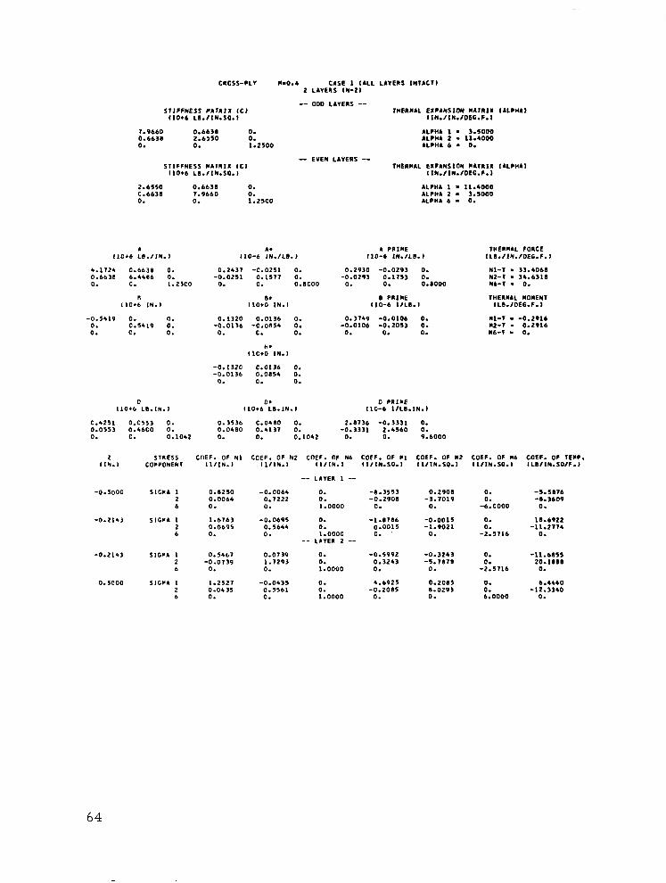
CIO5*-PL* M-0.4 CUE 1 (ALL LIVERS 1NlACll 2 LAVERS IN-21
STIFFNESS CAlRlX ICJ tio+b L8.fltd.sa.J
-- 000 L,“EIS -- IIIEAJUL EXPANSION 11711X IALPWAJ
l1N./lN.f06G.F.J
7.9660 0.6638 0. 0.6638 2.6550 0. 0. 0. 1.2500
SIIFFNESS LAlRlX ICI IlO+b LE..flN.Sa.l
2.6550 0.6638 0. 0.6638 7.9660 0. 0. 0. 1.2500
ALPHL 1 - 3.5000 ALPH. 2 - 11.4000 ALIH4 6 - 0.
- EVEN LIVERS -- THERMAL EXPANSION )lAlRlX IALPHAI
llN.flII.fOEG.F.l
ALPHA 1 = 11.4000 ALCH. 2 - 3.5000 ALP”. 6 - 0.
A A. A PlllLE 7nERllA~ FORCE 1,016 LB./ IN. J 110-b lN.fLI. J 110-b lN./LB. J IL8.fJN.fDEC.F.J
WI-T . 33.4068 112-7 . 34.6318 Nb-I - 0.
4.1724 0.66’8 0. 0.6631 6.4486 0. 0. C. 1.2500
II 11016 IN.,
-0.5419 0. 0. 0. 0.5419 0. 0. C. 0.
0.2437 -0.0251 0. -0.0251 0.1517 0.
0. 0. o.acoo
IlO+:*,N.,
0.1320 0.0136 0. -0.01’6 -C.0854 0.
0. C. 0.
H. llC+O IN.,
0.2930 -0.0293 0.
-0.029’ 0.1753 0. 0. c%ooo
0 PXINE 110-b 1fLI.I
THERMAL IIOI(EN7 tLB.IOEG.F.1
0.3149 -O.OlOb 0. MI-T . -0.2916 -0.0106 -0.2013 0. *z-7 . 0.2916
0. 0. 0. Mb-l . 0.
-0.132c 0.0136 0. -0.0136 0.0854 0.
0. 0. 0.
0 0. 0 PllME llO+b LE.IN.1 IlOt LB.lN., 110-b lfLB.lN.l
0.4251 o-c553 0. 0.3536 C.0480 0. 2.87’6 -0.3331 0. 0.0553 O.,bCO 0. 0.0480 0.41’7 0. -0.3331 2.4560 0. 0. C. 0.1042 0. 0. 0.1042 0. 0. 9.bOOO
2 STRESS t :OEF. OF N, COEF. OF Nt COEF. OF Nb COEF. OF *I COEF. OF “2 COEF. OF “6 COEF. OF TEMP. (IN., COCPONENT l1IlN.I ,l/,N., ll/IN.I tifiN.5a.i IlflN.sa.l ~lflN.sa.I lLOflN.5afF.J
-- LIVE” 1 --
-0.5000 SIGFA 1 0.8250 -0.0064 0. -8.3553 0.2908 2 0.0064 0.7222 0. -0.2908 -3.7019 6 0. 0. 1.0000 0. 0.
-0.2143 SlWA 1 1.6763 2 0.0695 6 0.
-0.0695 0.5644 0.
0. 0. 1.0000
-- LAVE” 2 --
-1.8786 -0.0015 0.0015 -1.9021 0. 0.
0. 0.
-6.0000
0.
-;:57,,
-5.5176 -0.3609
0.
10.6922 -11.2774
0.
-0.2143 SlGPA 1 0.5467 2 -0.0739 b 0.
0.5coo SIGCA 1 1.2527 2 0.04’5 6 0.
0.07’9 0. -0.5992 -0.3243 1.1293 0. 0.3243 -5.7871 0. 1.0000 0. 0.
-0.0435 0. 4.6925 0.2085 0.5561 0. -0.2015 I.0293 0. 1.0000 0. 0.
0. 0.
-2.5716
0. 0. 6.0000
-1l.bI55 2o.laBe
0.
6.4440
-1::3340
64
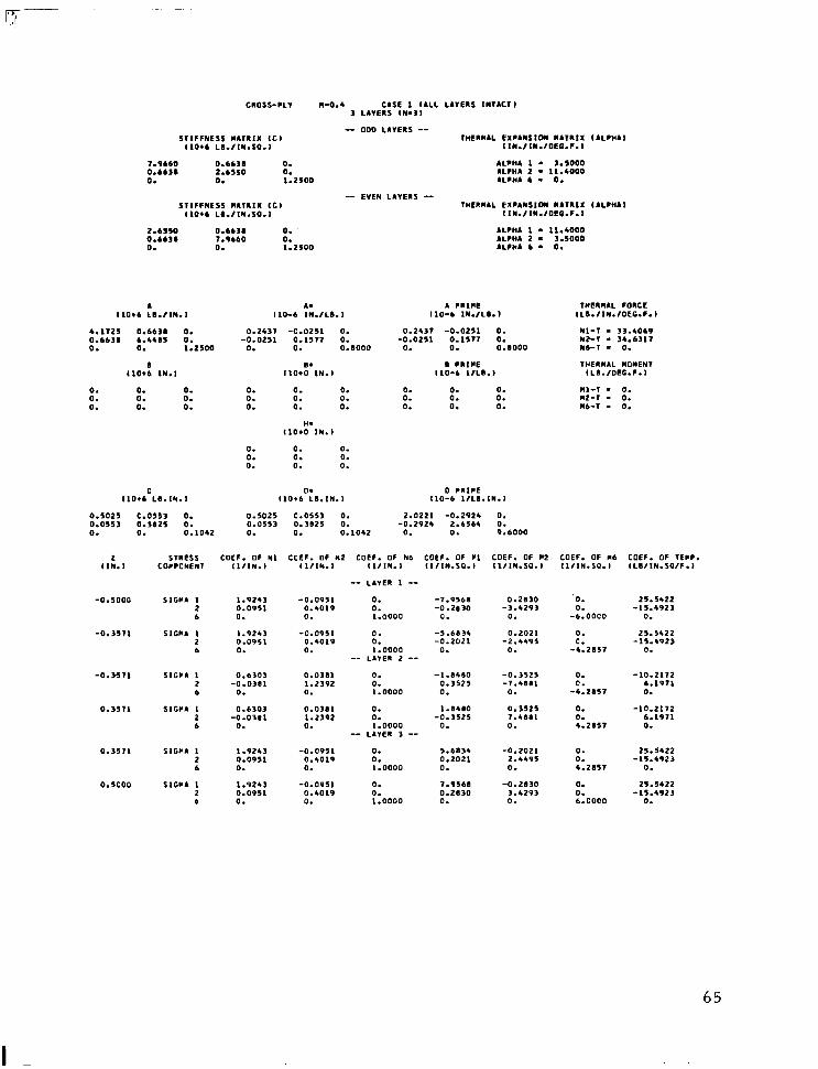
-
CRO5s-PLv II-o.4 CbSE 1 IALL LIVERS INVACTI 3 LIVERS lW=3l
5llFFNESS tiAlR,X ICI 110~6 LI.flN.SO.J
7.9660 0.6638 0. 0.6631 2.6550 0. 0. 0. 1.2soo
SllFFNESS )111111X ICI IlO+ LD.flN.5Q.l
- ODD LIVERS -- IHEXllAL EXFAN5lOII IAlllIX
llN.flN.fDEC.P.l
ALPH. 1 = 3.5000 ALP”A 2 - Il.4000 ALP”A 6 - 0.
-- EVE,, LIVEIS -- 7WEXII.L EXPAllSlOl “AVllX
I1N.flN.fOCG.F.J
I ALPHA J
(ALPHAI
2.6550 0.663. 0. ALPW 1 . 11.4000 0.6638 7.9660 0. ILCIM 2 - 3.5000 0. 0. 1.2500 ALPNA 6 - 0.
. A. 1 P”,“E V”E”“AL FORCE ‘lOI LI.flN.I 110-b 1N.fLI.l 110-b lN.fL8.1 lLI./lN.fOEG.F.l
4.1725 0.663# 0. 0.66’1 6.4415 0. 0. 0. 1.2500
0 1lOtb IN.1
0.2437 -C.O251 0.
-0.0251 0.1577 0. 0. ::,ooo
0.2431 -0.0251 0. WI-T . 33.4069 -0.0251 0.1577 112-V . 34.6317
0. 0. ::,ooo
Nb-T - 0.
I. B l “lPE IHEXIIAL MOMEN llO+O 1N.J 110-b l/LB., lLB./OEG.F.J
0. 0. 0. 0. 0. 0. 0. 0. 0.
0. 0. 0. 0. 0. 0. 0. 0. 0.
0. 0. 0. Ml-1 - 0. 0. a. 0. “2-7 - 0. 0. 0. 0. “b-7 . 0.
H. 110.0 IN.1
0. 0. 0. 0. 0. 0. 0. 0. 0.
E 0. 0 CRlFE llO*b LI.1N.l 110~6 LB.lN.1 110-b IILX.lN.1
0.5025 c.0553 0. 0.5025 c.0553 0. 2.0221 -0.2924 0. 0.055, 0.3825 0. 0.05s’ 0.3825 0. -0.2924 2.6564 0. 0. 0. 0.1042 0. 0. 0.1042 0. 0. 9.6000
STRESS COEF. OF WI CCEF. OF N2 COEF. OF Nb COEF. OF Cl COEF. OF “2 COEF. OF “6 COEF. OF TELP. COFPONENT Ilf1N.l ,111N.l ll,,N.l llf1N.sa.l ,,,111.*a., lifiN.50. i ILOfIN.Sa/F.l ,I:.,
-0.5000
-0.3571
-0.3571
0.3571
0.351,
0.5coo
-- LIVE” I --
-0.0951 0. -7.9568 0.4019 0. -0.2830 0. 1.0000 0.
-0.0951 0. -5.6834 0.4019 0. -0.2021 0. 1.0000 0.
-- LAlE” 2 --
0.0311 0. -1.84.50 1.2'92 0. 0.3525 0. 1.0000 0.
0.0381 0. l.ISIO 1.2392 0. -0.3525 0. 1.0000 0.
-- LA”ER 3 --
-0.0951 0. 5.68’4 0.4019 0. 0.2021 0. 1.0000 0.
-0.0951 0. 7.9568 0.4019 0. 0.2830 0. 1.0000 0.
0.2030 ‘0. 25.5422 -3.429’ 0. -1s.4923
0. -b.OOCO 0.
0.2021 0. 25.5422 -2.4495 0. -15.4923
0. -4.2857 0.
SIGMA 1 1.9243 2 0.0951 6 0.
SIGIIA 1 1.924’ 2 0.0951 6 0.
5lGCl 1 0.630' 2 -0.038, 6 0.
SltFA 1 0.6303 2 -0.0381 6 0.
-0.3525 0. -LO.2172 -7.488, 0. 6.1971
0. -4.2.57 0.
0.3525 0. -10.2172 7.4881 0. 6.1971 0. 4.2X57 0.
-0.2021 0. 25.5422 2.4495 0. -15.4923 0. 4.2.5S7 0.
-0.2X30 0. 25.5422 3.429’ 0. -15.4923 0. b.COOO 0.
SIWA 1 1.9243 2 0.0951 6 0.
SIGCA 1 I .9243 2 0.0951 6 0.
65
I -
CRCSS-PLY ".I.0 CASE 1 (ALL LA”ERS INlICll 2 LAYERS IN-21
S,,FFNESS CAlRlI ICI ,lO*b LB./lN.SP.J
7.9bbO 0.6638 0. C.6638 2.6550 0. 0. 0. 1.2500
-- “00 LAlElS -- THERPAL EXPANSION P4,“lX IALPHA,
IlN./lN./OEG.F.J
ALP”. 1 . 3.5000 ALPHA 2 - 11.4000 ILPhA 6 . 0.
STIFFNESS *A,RlX ICI 110.6 L8.IlN.SO.l
-- EVEN LAIERS -- THERPIL EXPANSION PA,“,1 ,ALPHAI
,IN.,lN.,CEC.F.l
2.6550 0.6638 0. ALPHA 1 - 11.4000 C.bb3.5 7.9660 0. ALPHA 2 . 3.5000 0. 0. 1.2500 ALPPA 6 . 0.
4 A. I1C.b LB.IlN.1 ILO-t 1N.ILB.I
5.3105 C.&b38 0. 0.66’8 5.3105 0. 0. c. 1.25CO
r ll0.b IN.,
-0.6639 0. 0. 0. C.b6,9 0. 0. c. 0.
C 0. 0 PYIPE ,10+6 LB.1N.I l,O*b LB.1Y.I 110-b 1,LB.lN.l
0.4425 C.C55' 0. 0.3582 0.044B 0. 2.8358 -0.3545 0. 0.0553 C.J.525 0. 0.044B 0.3582 0. -0.3545 2.8358 0. 0. 0. 0.1052 0. C. o.,crz 0. 0. 9.6000
0.1913 -0.0239 0. -0.0239 C.19,’ 0.
0. C. O.BCOO
R. ,lO+C IN.,
0.1270 c.0159 0.
-r,:Ol,, -C-l270 c. 0. 0.
k. ,,cto IN.,
-0.1270 c.0159 0. -0.0159 c.1210 0.
0. C. 0.
A PRl@E ,I,?-6 1N.ILB.I
0.2363 -0.0295 0. -0.0295 C.2’63 0.
0. 0. O.BOOO
B PRlClE IIC-6 1,LB.I
0.3545 0.0000 0. 0.0000 -0.3545 0. 0. 0. 0.
,l.ERRAL FORCE ,L”.llhl.lOEG.F.l
Nl-, . '4.0,9' NZ-1 - 34.0193 Nb-1 - 0.
THERl4.L llCMEN7 ,LB.,OEG.F.I
Ml-1 . -0.357, 112-l . 0.357, FL-1 - 0.
1 STRESS COEF. OF Nl CCEF. OF HZ COEF. CF Hb CCEF. GF PI CCEF. CF *2 COEF. OF Pb COEF. OF TEPP. 114.1 COCPONENT I,,lN., ,lIlN., IlIlY., I1,lN.SP.I ,l,lN.5a.l llI1N.SO.I 1LBllN.SOIF.l
-- LAlER I --
-0.5coo SIG*. 1 0.4509 0.0392 0. -8.353' 2 -0.0392 L.0784 0. -0.2353 0 0. (I. 1.000C 0.
0. SlGPA 1 l.Bb29 -0.0184 0. 2.8240 * 0.0784 0.6018 0. 0.2353 b 0. 0. 1.000C 0.
-- L&"EI 2 --
0. SlWA I 0.6078 0.0784 0. 0.9412 2 -0.0184 I.8629 0. 0.235' b 0. 0. 1.0000 0.
0.5ooc SIGPA L l.OIB, -0.0392 0. 4.58Pl 2 0.0392 0.4509 0. -c.2353 b 0. 0. 1.0000 0.
0.2'5' 0. -6.5881 0.
0. -b.COCO
-0.2'53 0. 24.1643 0. -9.6648 0. 0.
-0.9412 0.
-0.2353 C. -9.6648 -2.825C 0. 24.164,
0. 0. 0.
0.2353 0. 1.2075 8.353' 0. -15.7070 0. 6.0000 0.
-15.1010 l.tC75 0.
66

CROSS-PLY 11.1.0 C.SE 1 (ALL L.“E”S lNlACll 3 LIVE”* IN-31
STIFFNESS WA7”lX ,CJ 1,016 L1.flN.Sa.l
-- 000 LIVERS -- IHEIIWAL EXPANSIOII L.l”lX ,.LPH.J
4lN.llN.fOEG.F.J
7.9660 0.6638 0. ALPHA 1 . 3.5000 0.6631 2.6550 0. .LCHl 2 . 11.4000 0. 0. 1.2500 ALPHA 6 - 0.
SIIFFNLSS FA7”lX ICI ,I016 L”./lN.Sa.l
-- EVEN LAVEIS -- 1HE”“AL EXPANSION "Al"lX IALPHbl
llN.flN.fOEG.F.I
2.6550 0.6638 0. ALPM 1 . 11.4000 0.66’8 7.9bbO 0. AL.“. 2 l 3.5000 0. 0. 1.2500 ALPHA 6 . 0.
A A. I P”l”E 1HE”)IAL FORCE ILO. LO.IlN.1 110-b lN.,L”.l 110-b 1N.fLI.J lLO.flN.fOEG.F.l
5.3105 O.bb31 0. 0.66311 5.3105 0. 0. C. 1.2500
B IlC.6 IN.,
0.191, -c.o239 0.
.::o2'9 c.1913 0. 0. 0.8000
0.1913 -0.0239 0. WI-1 - 34.01*3 -0.0239 0.1913 0. 112-7 . 34.01.3
0. 0. 0.8000 Nb-I - 0.
I. ” P”lFE 184E”“IL llC”ENl tlC*O IN., 110-b lfLB.l lL”.fOEG.F.I
0. C. 0. 0. C. 0. 0. 0. 0.
0. 0. 0. 0. C. 0. 0. 0. 0.
Il. IlC.0 IN.1
0. 0. 0. "l-l - 0. 0. 0. 0. 112-7 - 0. 0. 0. 0. “b-l - 0.
0. C. 0. 0. C. 0. 0. 0. 0.
c 0. 0 PIIIPE 110.6 LI.IN.1 ‘IO+6 LB.IN. I ,lC-6 1,LB.lN.I
0.6085 C.0553 0. 0.6’285 C.055, 0. 1.6131 -0.334" 0. 0.0553 0.2766 0. 0.055’ C.2766 0. -0.3341 3.61126 0. 0. C. 0.1042 0. c. O.lC42 0. 0. 9.6000
1 SlRESS COEF. OF Nl CCEF. OF HZ COEF. OF Nb COEF. OF *I COEF. OF “2 COEF. OF “6 COEF. OF lE*P 1lN.I COCPCNFNI (1,IN.I 1lIlN.J I1,lN.I Ilf1N.SC.l ll/lN.Sa.l ll/lN.SC.I ,L”,lN.Sa,F.l
-- LAlE” 1 --
-0.5COO SIGCA 1 1.5010 -0.06’5 0. 2 0.06’5 0.4920 0. b 0. 0. 1.0000
-6.5556 -0.1111
0.
0.1111 0. 13.6921 -4.7716 0. -13.6921
0. -b.OOCO 0.
-0.25oc SIGCI 1 l.5Oc’C -0.0635 2 0.06’5 0.4920 b 0. 0.
0. 0. 1.0000
-- LA”E” 2 --
-3.277” 0.055b 0. -0.0556 -Z-,1”” 0.
0. 0. -3.0000
13.6921 -13.6921
0.
-0.2500 SlWA I 0.4920 0.0635 0. 2 -0.06’5 1.5O”O 0. b 0. 0. 1.0000
-1.0554 0.3189 0.
1.0554 -0.3889
0.
-0.31e.P -7.2194
0.
0.2500 SlWA I 0.492c 0.06’5 2 -0.06’5 1.5080 6 0. 0.
0. 0. 1.0000
-- LAIE” 3 --
O.‘B89 7.2784
0. 0.
-3.cooo
0. 0. 3.0000
-13.6921 13.6921
0.
-13.6921 13.6921
0.
0.2500 SIGPA 1 1.5000 -0.0635 2 0.0635 0.4920 6 0. 0.
0.5000 SIC*. 1 1.5080 -0.06’5 2 O.ObJ5 0.5920 b 0. 0.
0. 0. 1.0000
0. 0. 1.0000
3.2778 -0.0556 0. 13.6921 0.0556 2.31”” 0. -13.6921 c. 0. 3.c000 0.
6.5556 -0.1111 0. 13.6921 c.1111 4.7776 0. -13.6921 C. 0. b.COOO 0.
67

c”oss-PLV Il-2.0 CASE 1 (ALL LIVERS lN7.Cll 2 LIVERS IN-21
-- 000 LLVERS -- SIIFFNESS W.l”lX ICI THE”“.L EXPANSION “4111X I.LPH.J
llO+b L0.flN.5a.J I lN.fIN.fOEG.F.l
7.9660 0.6638 0. ALPHA 1 - 1.5000 0.6631 2.6550 0. ALPHA 2 . 11.4000 0. 0. 1.2500 ALPHA 6 - 0.
SIIFFNESS ,M,“,X ICI ,lO+b L0.flh.sa.i
2.6550 0.6638 0. C.6631 1.9660 0. 0. 0. 1.2500
- EVEN LAVERS -- 1HE”M.L EXPAN5lON “4l”lX I ALPHA,
I1N.fIN.fOEG.F.J
ALPHA 1 l 11.4000 4LPII. 2 . 3.5000 ALPHA 6 = 0.
A A. 4 CRICE 7WE”I.L FORCE IlO*. L”./lN.l 110-b lN.,L”.l 110-b ‘N./LB. I ILD.flN.fOEG.F.J
6.1951 0.6638 0. 0.66’8 4.4252 0. 0. C. 1.2500
II llO+C IN.,
O.lbW -C.O246 0. -0.0246 0.2297 0.
0. 0. O.ICOO
B. I1010 IN.,
0.1979 -0.0293 0.
-0.029’ 0.2415 0. 0. oo:sooo
I PRlFE 110-b l/L”.,
WI-1 . 34.4917 NP-I - 33.5429 Nb-1 . 0.
7PE”l.L “O”EN7 lLI.IOEC.F.1
-c.5901 0.
5:59,1 0. 0.
0. 0. 0.
0.0968 0.0145 0. -0.0145 -0.1355 0.
0. 0. 0.
H. llCt0 IN.1
0.2449 0.0017 0. Nl-1 - -0.3175 o.co.7 -0.3036 0. “2-7 . 0.3175 0. 0. 0. “6-T - 0.
-0.096@ c.0145 0. -0.0145 0.1355 0.
0. C. 0.
0 0. 0 F”,FE IlO. LB.1N.I 11016 LB.lN.1 IlC-b 1fLI.IN.l
0.4507 c.0553 0. 0.3936 C.0467 0. 2.5809 -0.3405 0. 0.0553 c-4343 0. 0.0467 0.3544 0. -0.3405 2.1660 0. 0. 0. 0.1042 0. 0. O.lC42 0. 0. 9.6000
2 STRESS C OEF. OF Nl CCEF. OF N2 COEF. OF Nb COEF. OF l l COEF. OF “2 COEF. OF Mb COEF. OF TI?lP. I IN., COCPCNENI Ilf1N.l ~lflN.1 llf1N.l l1flN.Sa.J l1f1N.sa.l flfIN.5C.l ILIf1N.SafF.l
-- LIVE” 1 --
-0.5coc SlGCA I 0.4918 0.0460 0. -4.2104 0.2191 0. -14.0221 2 -0.0460 1.2’43 0. -0.2191 -4.7054 0. 5.“021 6 0. 0. 1.0000 0. 0. -6.0000 0.
0.1667 SlWl 1 1.0032 -0.0777 2 0.0771 0.5592 6 0. 0.
0. 0. 1.0000
-- LIVE” 2 --
5.3460 -0.3205 0. 22.346’ 0.3205 0.2145 0. -11.1442 0. 0. 2.0004 0.
0.166, 5lGP. 1 0.58Bb 0.0704 2 -0.0704 1.714. b 0. 0.
0. 0. 1.0000
I .7605 -0.0651 0.0651 0.1194 0. 0.
0. 0. 2.0004
-10.5036 19.1505
0.
0.5COC SIGC. 1 0.8072 -0.0068 0. 3.9691 0.2679 0. -6.1474 2 0.0061 0.6983 0. -0.2619 0.2557 0. -9.0841 6 0. 0. 1.0000 0. 0. b.OOCO 0.
68
CRCSS-PL” “-2.0 CASE 1 ,LLL LAYERS INrAcTl 3 LI”EIS IN-31
-- 000 LAYERS -- STIFFNESS CA,RIl ICI THEIFAL EIFANSION *AIRI%
(IO.6 Lo./1N.sa.l IIN./IW.IOEG.F.I
7.9660 0.6631 0. ,LPH. 1 - 3.5000 0.6638 2.6550 0. ALFHA 2 = 11.4000 0. 0. 1.2500 NC”. 6 . 0.
-- EVEN LIVERS -- S,,FFNESS FATRIX IC) THBIICIAL EXPANSION “.T”,l,
,,0,6 LI.,,N.SC.I IIU./[email protected]
2.6550 0.6638 0. ALFHA 1 - 11.4000 0.6638 7.9660 0. ALFlU 2 - 3.sooo 0. 0. 1.2500 ALCIIA 6 * 0.
A. I LO-6 ,N.lLl,. I
1 PRlFE ,,o-6 ,N.,LB.,
THERMAL FORCE ILI.IIN.~DEG.F.l
Nl-7 - 3*. ,936 NZ-7 - 33.5430 Nb-I - 0.
7HE”“lL “O”EN7 ILB.fOEC.F.l
Ml-, - -0.0000 “2-7 . -0.0000 “6-T - 0.
I 1,016 LB./IN.)
6. ,4S6 C.6638 0. 0.6638 5.4254 0. 0. 0. ,.2500
B IlCIL IN.1
0.16,O -C.O256 0. 0.1640 -0.0256 0. -0.02C6 0.2297 0. -0.02~6 0.2291 0.
0. 0. 0.8000 0. 0. 0.8000
8. B PI,“E ,,O+O IN.1 I IO-6 ,,LI.l
0. 0. 0. 0. 0. 0. 0. 0. 0.
H. ,,c+o IN.1
0. 0. 0. 0. 0. 0. 0. 0. 0.
0. 0. 0. 0. 0. 0. 0. 0. 0.
0. 0. 0. 0. 0. 0. 0. 0. 0.
0 0. 0 PR,FE 110.6 LB.IN.1 110.6 LB.1N.l (10-b lIL8.IN.I
0.6414 0.0553 0. 0.0553 0.2376 0. 0. 0. 0.1052
0.6475 c.0513 0. 0.0553 C.2376 0. 0. 0. 0.1042
1.11759 -0.3668 0. -0.3t.68 5.29% 0.
0. 0. 9.6000
CCEF. OF q 2 COEF. OF F6 COEF. OF 7ElF. ,,,,Iy.SP.l l,/lN.SQ.I 1LIIIN.SPfF.l
I (IN.1
-0.5000
-0. ,661
-O.,LL,
0.1667
0.1667
0.5coc
STRESS COCPCNENT
SIGFA I 2 6
SIG*. 1 2 6
SIGPA 1 2 6
SIGCL 1 2 6
S,CCl 1 2 6
SlGCl 1 2 6
COEF. OF N, IlIIN.1
COEF. OF N2 COEF. OF N6 COEF. OF PI I LIIN.1 Il/IN.l tilIr(.sa.)
-- LA”ER 1 --
-0.0536 0. -6.,550 0.5934 0. -0.0361 C. ,.oooo c.
-0.0136 0. -2.05,7 0.5934 0. -o.o*zo 0. ,.oooo c.
-- LA’IE” 2 --
0.0161 -5.5177
0.
0.0120 -,.I593
0.
0. 0.
-6.0000
0. 0.
-2.cooo
1.6041 -11.1027
0.
7.t.01, -1l.lcl27
0.
L-2904 0.0136 0.
L-2904 0.0536 0.
0.001, 0. -0.6568 1.8,3, 0. 0.3127 0. ,.oooo 0.
-0.3127 -5.6597
0.
0.3127 5.6591 0.
0. 0.
-2.0000
0. 0. 2.0000
-1S.2077 22.36.7
0.
-1S.2077 22.3611
0.
0.+,92 -0.087,
0.
0.0871 0. 0.6568 1.8131 0. -t.3,27 0. 1.0000 0.
-- LAIE” , --
-0.0436 0. 2.0117 0.5934 0. 0.0120 0. 1.0000 0.
-0.0436 0. 6.1550 0.5934 0. 0.03bl 0. 1.0000 0.
0.4,92 -0.0171
0.
-0.0120 1.8593 0.
-0.036, 5.5777 0.
0. 0. 2.0000
0. 0. 6.0000
7.604, -11.1~27
0.
1.6011 -11.1127
0.
1.2904 0.0436 0.
L.2904 0.0436 0.
69

CROSS-PLY “.,.O CASE I (ALL LIVERS INTACTI 2 LAYERS IN-21
-- 000 LAYERS -- S,,FFNESS Cl,IIX ICI THElllllL EXPlNSlON “671111 I,LPHA,
11o+c L8./IN.SO.l l,N./IN./OEC.F.l
1.9660 0.6638 0. ILPCA 1 = 3.5000 0.6630 2.6550 0. ALP”. 2 . 11.6000 0. 0. 1.2500 6LPHA 6 - 0.
-- EYEN L6”ERS -- STIFFNESS bA,RIX ICI WERCLL EXPINSION IIA?IIX IALPHA)
(1016 L0.IIN.SP.l IIN./IN./CEG.F.l
2.6550 0.6630 0. 6LPhl 1 . 11.4000 0.6638 7.9660 0. ALPHI 2 - 3.5000 0. 0. 1.2500 lLPH6 6 . 0.
L A. A PIIIVE ,I-E”“.L FORCE 1,016 LB./IN.1 (10-b IN.fL0.I 110-6 1H.IL6.1 IL6./IN./DEG.F.l
6.9030 0.6630 0. 0.1614 -0.0263 0. 0.6630 3.1112 0. -0.0263 0.2737 0. 0. c. 1.2500 0. 0. O.BCOO
0 8. (IO+6 IN.1 IICIO IN.,
0.1559 -0.0293 0. Nl-1 * 34.0761 -0.0293 0.3130 0. NZ-, . 33.1619
0. 0. 0.0000 Nb-1 - 0.
0 PRIPE (LO-6 lIL0.I
,kElllllL LO”EN, lL8.IOEG.F.I
0.1336 0.0128 0. O.Cl21 -0.3306 0. 0. 0. 0.
“1-l . -0.2216 *2-, - 0.2286 Mb-1 . 0.
-0.4249 c. 0. 0. 0.4249 0. 0. 0. 0.
0.0626 0.0112 0. -0.OL12 -0.1163 0.
0. 0. 0.
H. ,,O+O IN.,
-0.0626 c.0112 0. -0.0112 C.1163 0.
0. C. 0.
0 0. 0 PLIPE IlOtb LE.IN.1 (IO*6 L0.,N., 110-b 1,LB.IN.I
0.4903 o.c553. 0. 0.4637 C.0506 0. 0.0553 c.3947 0. 0.0506 c.,453 0. 0. C. 0.1042 0. C. O.lCSZ
2.1914 -0.3209 0. -0.3209 2.9420 0.
0. 0. 9.6000
2 STIIESS , :OEF. OF NI CGEF. OF NZ COEF. OF N6 COEF. OF PI COEF. CF 112 COEF. OF 116 COEF. OF ,ECIP. IIN. COCPCNEhl ,,/,N., ,I,IN., I1,IN.I tIfIN.sa.1 ~if~h.s.0.I lIfIN.SC.1 ,LB/,N.SO,F.,
-- LdlEl 1 --
-0.5coc SIGCA I 2 6
0.3coc SIGFA I 2 6
0.6059 -0.0351
0.
1.5453 0.0625 0.
0.0357 I.2566 0.
-0.0625 0.5443 0.
0. -7.5430 0.1716 0. -0.5700 0. -C.l,86 -4.6906 0. 6.0103 1.0000 0. 0. -6.0000 0.
6.2461 -0.3035 C. ,4.*407 C-3035 1.3894 C. -12.1131 0. 0. 3.6000 0.
0. 0. 1.0000
-- LI"ER 2 --
0. 0. 1.0000
0. 0. 1.0000
2.0448 -0.1397
0.
3.1659 -0.3600
0.
0.1397 4.2795 0.
O.,bOO 8.9254 0.
0. 0. 3.6000
C. 0. 6.0000
-13.0¶61 10.3017
o.,coo SiGPA 1 2 6
0.5coo SIGPA 1 2 6
0.5034 -0.0727
0.
0.5761 -O.O,,b
0.
0.0727 ,.bbbB 0.
0.0346 1.1290 0.
0.
-11.9939 2.9094 0.
70

CICSS-FLY *=4.0 CASE 1 (ALL LIVE46 ,II?,C?l 3 LAYERS (N-31
-- 000 LAYERS -- STIFFNESS LIIRIZ ICI 1HLRPAl. EIF4NSION FAlRIX
IlOIb LB.,IN.SC.l IIn.fII./DCG.C.I
7.9660 0.6638 0. aLPma 1 n 3.1000
0.6638 2.bS50 0. ILCli4 2 - 11.4000 0. 0. 1.2500 ALCCA 6 - 0.
-- STIFFNESS *amix EVEN LIVERS -- *cl THElFlL EXPANSION CAl”II
IlO+ LB./IN.SO.l IIN.fIh.fCEC.F.1
2.61SO 0.663# 0. 4LCHA I - 11.4000 0.6631 7.9660 0. 4LFHA 2 - 1.5000 0. 0. 1.2100 bL,H. 6 - 0.
I bLFn4l
l4LFHbI
4 IlC+b LB./IN.,
6.903. C.663. 0. 0.6631 3.7176 0. 0. 0. 1.2500
I ilO+ IN.1
110-b ::.,,,.I
0.1*74 -0.0263 0. -0.0263 0.2737 0.
0. C. O.ICOO
,ld’IN.I
o.ocoo c.0000 0. -0.0000 -0.0000 0.
0. 0. 0.
H. IlOIO Ife.1
-O.OcOC 0.0000 0. -o.cooc 0.0000 0.
0. C. 0.
4 FllFE 1”E”“AL FOICE 110-b 1N.fLI.l ILI.fIN./OEC.F.I
0.1474 -0.0263 0. 11-l l 34.176
-0.0263 0.2737 0. *2-r - 33.162, 0. 0. 0.8000 Nb-1 = 0.
0 FIIIIE THEIIIIL q OMEl(l 110-b 1fLb.I ILI./OEG.F.l
0.0000 0.0000 0. 0.0000 -0.0000 0. 0. 0. 0.
II-1 - -0.0000 "2-l . 0.0000 116-l - 0.
-0.0000 0. 0. 0. 0.0000 0. 0. 0. 0.
D 0. 0 PlIFE 1,016 LI.1N.l (IO.6 Lb.IN.1 110-b I/LI.,N.,
0.6601 o.os53 0. 0.6603 c.0553 0. 1.54bb -0.3105 0. 0.0553 0.2251 0. 0.0153 0.2264
::1012 -0.310¶ b.%Zl 0.
0. 0. 0.1042 0. C. 0. 0. 9.6000
2 ST”ESS COEF. OF Nl COEF. OF N2 COEF. OF Nb COEF. OF Fl COEF. OF “2 COEF. OF I’6 COEF. OF TEFC. (IN.1 CO”PCNEN1 II/IN., 11flN.l 11,lN.l 11fIN.sa.l 1ifIn.sa.I 11flN.SO.l ILI/III.sa,F.l
-- LLIE” 1 --
-0.5000
-0.1000
-0.1c00
0.1c01
0. LCOI
0. SC00
516114 1 2 6
SIGCA I 2 6
l.lSbb -0.0210 0. 0.02.0 0.7092 0. 0. 0. 1.0000
l.lS66 -0.0240 0. 0.0280 0.7092 0. 0. 0. 1.0000
-- L4”E” 2 --
-6.032. 0.00.1 0. 3.9620 -0.001, -5.9035 0. -1.0914
C. 0. -6.0000 0.
-1.2065 0.0016 -0.0016 -1.18OI
a. 0.
0.
-~:2000
3.9626 -..0967
0.
SIGN4 1 0.313. 0.1111 0. -0.3”53 -0.2OOS 2 -0.1118 2.1628 0. o.zoc5 -3.5914 6 0. 0. 1.0000 0. 0.
-l,..,,, 32.37¶0
0.
SIGPl 1 0.3131 2 -0.1118 6 0.
0.111~ 0. 2.1627 0. 0. 1.0000
-- LIIE” 3 --
0.3.56 0.2006 -0.2006 ,.wsz
0. 0.
0. 0.
-1.2000
0. 0. 1.2001
-15.1**3 32.3729
0.
SIG*1 1 I.1566 -O.OZbO 0. 1.2075 -0.0016 2 0.024c 0.7oe2 0. 0.0016 1.1814 6 0. 0. 1.0000 0. 0.
0. 0. 1.2001
3.9610 -1.09T4
0.
SIG?1 I 2 6
I.1566
kozec
-0.0280 0.7091 0.
0. 0. 1.0000
6.0330 -0.001, 0. 3.9631 o.ooe, 5.9033 0. -8.09.7 0. 0. 6.0000 0.
71

c.Q,ss-PLt ~n.o.2 C&SE 2 (ALL LA;E,X DEGRAOill : 2 L."iHS (k.2)
-- SrIrFrLss MATRIX
ocb Ll"5RS -- tc, ,HER"AL CXP&iSION "ATRIx ,ALPH,,
(lo** LB.fIH.SO.) (1N.IIN.IDEG.F.)
7.0000 “.a000 0. ALPHA 1 = 1..5oon G.llOOO o*aooo 0. ALPH4 2 = 11.4ooa 0. 0. G*"UOO *LP”A6= 0.
_- -IVEY LAlLRS -- STIFFNLSS NATRIX IC) TWER~AL EYPAYSIOH “ATRIX (ALPHA,
(lG.6 Ln.IIN.SU.) ~I,,.IIY./OEG.F.~
n.OOOO G.0000 0. *LPY. 1 = 11.4000 0.1~000 7.0000 3. ALPHA 2 i 3.500” u. n. G.OO”a 4LPIl.b. 0.
A PRIME (10-b IN./LBi)
THEI(*AL FOA:E ,,.I./Ih./OEG.F.,
Nl-1 . 4.5509 NL-T . 22.749, Pi*-, . a.
,“E”**L MOM:N, LLO.IOEG.F.1
Ml-1 . -1.096, nr-7 . 1.0961 “6-1 s 0.
50.4172 -G.0GOO 0. -“.““OO 0.1723 0.
". 0. 0000.011OQ
B PRIME ,111-b l/LB.)
138.3611 -a.oJGo 0. -a.ouaa -0.2216 0.
0. 0. 0.
0 PRIME (10-b 1ILFl.IY.l
3JZ.GLIO1 -G.GJoo 0. -“.O”“O 2.6500 (1.
". 0. aaGG.vo""
COEF. OF *1 IlIIN. B
-- LAIEH 1 --
COEF. OF “6 (IfIN.SO.~
COEF. OF TEMP. IL3/IY.SOIF.l
II. ". l.G"OO
a. (I. 1.0000
-- LAIE” 2 --
-215.8961 -".0000
".
213.89,4 u.0003 0.
0.000" u.0003 0.
-0.00117 -G.a”OO
0.
0. 0.
'3.YPYS
0.oan.s -0.00"O
0.
o.oooa 1.YZOZ a.
d."OOO 0.4790 0.
“. 0. 1.0000
(1. 0. 1.0000
-"."ooa -0.6407
0.
P.O"O" B.h.07 " .
0. 0.
-3.9996
0. 0. b."OOE
-O.n"OO O.O"OG 0.
-0.011ao -O.O""O
0.
U.0003 -".aGGL
".
72
B -
,’ I : ,:
.
CROSS-PLY H.0.2 CASE 2 (ALL LLIERS OEGRAOEO, 3 LA”ERS (N.3,
-- 000 LLYERS -- STIFFHESS "ATIIIX (C, THERWL EXPANSION MATRIX
IlG.6 LB./III.SO., (IN.IIN.IOEG.F.I
7.0000 0.0000 0. ALPHA I i 5.5000 a.0000 0.
koooo 0. ALP”. 2 . 11.400” o.aooo ALPH.b= 0.
-- FVFN LAYERS -- _._ STIFFNESS MATRIX ICI ,HES”AL EXPANSION MATRIX
(10.6 LB.IIN.SO.1 lIH./IN./OEG.F.,
(ALPHI,
IALPHA)
0.0000 0.0000 0. 0.0000 7.1000 0. 0. 0. O.OO”O
ILPIIA 1 = 11.400” .l.PH. 2 = J.5000 ALP&l. 6 . 0.
110.6 :B./Iw.l
I.2999 O."OOO 0. O.OO"O b.5001 0. I. ". 0.0000
0 (IO.6 IN.,
0. 0. G. 0. a. G. 0. a. G.
A. A PRIME (10-6 IN-/LB., (lo-6 IN.ILB.,
0.7693 -o.aaGll 0. -“.O”“G 0.1530 0.
U. 0. GOOO.G”“G
B PRIME (IO-6 1,LB.l
a. 0. 0. U. 0. 0. U. 0. 0.
THEH*AL F3P3C (LI.IIN./OFG.F.,
0.7693 -G.Gaoa 0. -G.aGGa O.lSdB 0.
N1-1 . 4.5.98 NZ-T . 22.7502 Nb-1 . 0.
T”ERnrL “OREN, tL0.IOEG.F.)
Ii,-T = 0. Mz-T . 0. “6-T . n.
“. 0. 0000.0000
8. ,10-u IN.,
0. a. 0. 0. a. a. 0. 0. 0.
H* llG.0 IN.,
0. u. a. 0. a. 0. a. 0. 0.
0. llO.6 LB.IH.,
0 PRIME (lo-6 lILB.IH.,
3.6519 -0.0JOO 0. -a.ou11a 2.6584 0.
II . 0. 0000.0a00
0.2738 o.oGa” cl. 0.0000 0.3762 0. 0. 0. 0.0000 0. 0. o.oooa
2 STRESS COEF, OF N1 (IN.1 COMPONENT (1111.1
COEF. OF N2 COEF. OF N6 COEF. OF “t LlIIN., (l/IN., (l/IN.SO.,
-- LAIER 1 --
-a.oaoo (1. -14.2422 u.oaoo -“.OGOJ 0. ~:Gooo “.
COEF. OF ~2 COEF. OF “6 l l/IN.SO.I ,,lIN.SO.l
-0.5000 SI3Ml I 2 6
-0.4167 SIZNL I 2 6
6.0”02 “.GGGO G.
b.GGOZ “.oaao 0.
0.0000 -G.Gooa
0.
G.0000 -0.0000
G.
6.0002 o.oaGG 1.
6.0002 “.OOOO a.
O.“OO” -“.Gaa”
0.
“.“OOO . ” . II ” 0 0
0.
a. a.
-6.uooa
o.“c!ao -G.““OG
0.
O.“““G -O.“n”O
0.
-o.GGoa II* -11.0606 o.oooa US -“.a037 u. l*OUOO U.
-- LAIER 2 --
0. D.
-5.o”ac
-0.1167 SIGMA I 2 6
0.4161 SIG”, I 2 6
“.OOOO U. -u.ooaa 1.2000 a. U.0000 U. 1.aooo U.
“.G”ao 0. “.aooJ 1.2”OO 0. -0.OG00 a. 1.0000 U.
-- L.“ER 3 --
-“.“ooo a. 11.06Bb “.a000 U.000” u. ::a,,, U.
-o.oooa a. 14.2422 u.uaao a. “.oGao 0. 1.0000 U.
-u.uaoo .0.bJPP
0.
U.000” 0.6399 D.
a. -g:CW,
-G.OGOO G.0000 0.
-O.oono G.UOOO 0.
0. 0. 5.0006
0..,67 SIG”, 1 z b
a.5000 SISMl 1 2 6
.0.0000 O.“OO” 0.
-o.aooa O.G”G” “.
G.OO"O -O."l3"0
0.
0.00'10 -G.oaoo
0.
0. 0. 5.0000
0. a. 6.0000
73

CROSS-PLV Nl0.4 CASE * (ALL LA’IERS uEGR*OEll 2 L4YERS (H=zl
-- 000 LAYERS -- SlIFFNESS NATRIX (Cl ,HER"AL CXPANSION MATRIX (ILPHA,
(10.6 Ld./IN.SG.l l IN.IIN./DEG.F.,
I .BOOQ 0*0000 0. ALPIdA 1 i 5.50011 0.0000 0.0000 0. A-PH& 2 i 11.4000 0. 0. 0.0000 ALPHL b i 0.
-- EVEN LAYERS -- STIFFYESS “ATRIX (Cl ,HER"AL E*PIUSIOH q lTRIX (ALPHA,
110.6 LB.IIN.SQ.) ~IN./IY./DEG.F.,
0.0000 7.0000 I.
0. 9. rJ.0000
ALPHA 1 = 11.4000 ALPHA 2 i 3.5000 ALPHA 6 i 0.
A A. * PRIME (10.6 LB./IN., (10-b IN.ILB.1 (10-b IN.,LB,)
0.4487 -O."OOO 0. -O.OlOO 0.1795 0.
0. 0. 00J0.0000
8. (10.0 IN.1
8.8637 -0.0000 0. N1-T . 7.799b -".O"OO 0.265* 0. rul-T = 19.5004
". cl. 0000.0000 rrb-T . 0.
2.2285 O."OOD 0. 0.0000 5.5715 0. 0. 0. 0.0000
I (1016 IN.,
THEH*AL "GnELll ILS.,OEG.F.,
-Be7959 0. 0. 0. 0.7953 0. 0. 0. 0.
0.3571 -0.0001
0.
0.000” 0. -0.1428 0.
0. 0.
23.5614 -o.Dooo Q. *l-T . -2.7856 -0.0000 -0.6030 0. W-T = 2.755b
0. 0. 0. "0-T = 0.
n* ~10fO IN.)
-0.3571 0.0000 0. -0.0000 0.1428 ".
0. 0. 0.
0 (10'6 LB.IN.)
0 PRIME ,l"-6 lIL.S.IN.,
0.2994 0.0000 0. 0.0152 0.0000 0. 65.9705 -o.ocoo 0. O.OO"O n.3505 0. 0.0300 0.2369 0. .".O""O 4.2213 0. 0. 0. 0.0000 0. 0. 0.0000 ". 0. 0000.00~0
2 STRESS COEF. OF Nl IIN., COIIPONEY, Cl/IN.)
COEF. OF “1 COEF. OF “2 COEF. OF PI6 COIF. OF TEMP. ll/lN.SP., ,l,IN.5Q., IIIIN.SQ.1 ,LB,IU.SQ,F.)
-- LA,ER 1 --
0. 0. 1.0000
-“.5000 SIGMA I -22.7526 2 -0.0003 6 0.
-75.5064 -0.0000
U.
0.0000 -O.0000
0.
.“.!I000
.“.“lJOO “.
0. 0.
-o.“ooo
-0.0002 -0.00"0
0.
0. 0. 1.0000
-- LAYER 2 --
73.5063 U.000~ u.
0. 0.00"2 1. -O.DO"O
-2.5716 0.
-0.2143 jI;MA 1 2 6
0.5000 jIS*& 1 2 6
0. 0. 1.0000
" .DOOG 0.0000 u.
0.0001 -".0003
0.
0.0000 11.095
u.
0. 0.
-2.371,
-0.0000 I.“000 0.
0. 0. 1.0000
0. 0. b.“OOC
-O.O""O -0.00n0
0.
74

CR,SS-':.I "au.4 CASE 2 (ILL LllERS DEGRAOEO1 1 L."ERS (11.3,
-- 00" LAYiRS -- STIrFYESS ".TRIX tit THERMAL EXP4YSION NITRIX
(ID.6 LB.IIN.SO.1 ,Ih./IH./OEG.F.,
I.SQOO 0.0000 a. ALPHA 1 . J.5000 Q.oaoo a. ALPHA 2 = 0. knooo
11.400" tl.oooo ALPnAb= 0.
_- LdtN LIVEHS -- STIFFNESS “ATRIX ICI THERWL EXPlYSION “ATRII
(1Q.b La.IIN.SO.1 ,I~./IY./DEG.F.1
U.UOOQ 0.0000 I. ALPHA 1 * 11.4000 Q.PDOO 7.8000 a. ALPHI 2 . 3.5000 (1. 0. 1.0000 ALPHAL= 0.
,10-o LLlI”.,
2.228b O.i~OOQ 0. O.QQOO 5.5714 0. 0. 6. 0.0000
i (10.1 IN.,
0. c. 0. 0. n. 0. 0. II . 0.
b (1ll.b LB.IY.,
0.4131 ".""OO 0. 0.0000 O.C3b9 0. 0. ". 0.0000
2 , IN. B
-“.5ooQ
-0.3571
-0.3571
0.1571
0.3571
0.5000
STRISS COEF. OF N1 ClM=OVEY, (IIIN.,
5I:Mh I 2 5
SIZMA 1 2 b
3..993 “.“00” 0.
3.4992 Q.0000 0.
51;*a 1 2 5
sran4 1 2 b
0.0003 -Q.QQOJ
0.
Q.O""J -0.0000
n.
s1:*4 I 2 5
SIGML 1 2 i
3.4993 -0.0000 0. b.7432 1.0003 Q.U"QO 0. 0.00~0 0. ". 1.0110 0.
3.4993 -0.0000 0. v.4402 o.oooa 0.0000 0. ".a000 0. I). 1.0000 0.
(IQ-b K./Lb.,
0..187 -Q."O"U 0. -0.0000 0.1795
0. 0. 005~:0000
0. ,l".O IN,,
0. 0. 0. 0. 0. 0. 0. 0. 0.
II*
,lQ'U IN.1
n. 0. 0. 0. 0. 0. 0. 0. 0.
"I ,lO.O LB.1H.I
Q-4131 O."Q"O 0. 0.0000 Q.LJbP 0. 0. 0. 0.0000
A PRIIIE IlU-6 IN.ILE.1
IHE"*AL FORX ILB./IN./OEG.F.l
U.4487 -o.ooQo 0. Nl-T . 7.8002 -".O"OO 0.17P5 a.
0. 0. 0000.u000 ;i-; : 19.4PPO
0.
0 PRIME T"EN"AL NONEWT 110-b l/La.) (Ld./OEG.F.l
0. 0. 0. "1-T s 0. U. 0. 0. PIi!-T . 0. 0. 0. 0. Mb-T . 0.
0 PRIME ,l”-6 lILB.IN.1
Z..znb -0.0000 0. -o.o"oo 4.2216 0.
0. 0. 0000.0005
3”LF. OF Y2 CJIF. OF Nb COEI . OF "1 (l/IN., llIIN.1 ,lllk.SO.,
-- LAYER 1 --
-".QQoo 0. -9.4402 ".0000 0. -".oooQ u. l.O"OO U.
-Q."ooo 0. -6.7.30 Q.U"UO 0. -0.0000 0. 1.0000 ".
-- LA"ER 2 --
Q.OQOU 0. -".ooQQ l..""" 0. ".QOOQ 0. 1.00QQ 0.
0.0d00 U. ".OQQQ 1.4000 0. -u.ooQo 0. 1.0000 U.
-- LAIER 3 --
CUIF. 5F "2 COEF. OF Mb CUEF. OF TE*P. ,lllN.5Q., (lIIN.SO.) ,L3/T".SO,F.,
0.0000 .O.“QQO
0.
Q.Q”U” -0.000”
0.
-,‘.QQoQ ‘11.7602
0.
Q.QOUO 11.7602
0.
-0.0000 0.0000 0.
-0.QQoo O.UQOU 0.
0. o.oooa 0. -0.0”“”
-b.OOOG 0.
0. 0.01100 0. -O.“cl”O
-4.L857 0.
0. -0.“0”0 0. 0.0000
-4.2857 0.
0. -0.oon0 0. 0.0000 4.2.557 0.
0. 0.0000 0. -0.0000 ,.2.557 0.
0. 0.0000 0. -0.0000 b.OOOG 0..
75
CROSS-PLY M81.0 CASE 2 (ALL LAYERS OEGRAOEII 2 LAYERS ,tm21
-- ODD LAYZHS -- S?IFFYESS WlTRIX fC1 THERllAL EXPAHSION MATRIX (ALPHA,
(10.6 Ltl./Ik.SO., ,IN.IIN.IOEG.F.I
7.8300 0.0000 3. ALPUL 1 = 3.5000 ".QQOO Q.QQOO 0. ALPHA 2 . 11.4000 0. n. a.0000 ALPHh b . 0.
-- EVEN LAYERS -- STIFFYESS MATRIX cc, WERNIL EXPANSION MlRIx IALPHA)
(lo.6 LB./IN.So., ,IN.IIN./OEG.F.l
0.0000 0.0000 a. ALPNA 1 . 11.4000 0.0000 7,.5000 0. ALP@84 2 * 3.5000 0. 0. l.QUOO ALPHa b . 0.
A PRIME THEN-AL FORCE flu-b 1N.ILB.j ,LB./IN./OEG.F.l
J.9000 Q."OQO ". 0.2564 -u."Qo* 0. 1.0256 -0.0300 0. 0.0000 3.3000 0. -0.0000 Q.2ib. 0. .U.OQOO 1.9256 0. 0. (0 . 0.0000 0. 0. 0030.0""" 0. 0. 0000.U~""
0 0. G PRIME (1Q.b I"., ,lQ+Q IN.) Ilo- lIL0.1
-0.9750 0. 0.
0. Q. 0.2500 Q.QQOQ 0. J.Qlt.9 0.0000 0. u.975, 0. -0.0000 -O.Z>UO 0. -I).""00 -3.0769 0. 0. 0. 0. 4. 0. 0. 0. 0.
H. ,,Q*Q IN.)
-0.2900 Q.OO"O 0. -0.0000 0.250" 0.
0. 0. 0.
0 0. D PRIME (111.6 LE.IY.1 ,lQ.b L0.IN.j (10-b lILR.IY.1
0.3250 I;.dnoQ 0. 0.0313 0.0""" 0. 12.31177 -0.0300 0. 0.0000 0.3250 0. 0.0000 0.0613 0. -".O""Q 12.3~77 0. 0. 0. 0.0000 Q. u. O.QQQO u. 0. 0000.0"""
I STRESS COCF. 3F 112 f1N.j COMPONEYT
CO::;I~IF,N~ cOW;I;F,u2 COW;IiF,Nb COEF. OF 14% 1111N.So.l ,l/~N.SO.l
-- LAYER i --
-0.5000 SIGMA 1 -4.0000 0.0000 0. -24.0003 0.0000 2 -0.0003 0.0000 0. -"."oQO -u."ooo b 0. 0. 1.0~0” 0. 0.
0. SIGMA I 0.0000 -O.O"QU 0. 24.OQQ5 -U."QQ" 2 0.0000 Q."OUO 0. ".OQ?o -o.uQo" 6 cl. 0. 1.0000 U. 0.
-- LA"E" 2 --
0. SIOMA 1 0.0003 U.0000 0. 0.0000 -B.oooo 2 -0.0000 d.OUOQ 0. 0.00~0 -24.UQQo 4 0. 0. 1.0900 u. D.
0.500" jI3M)1 1 Q.QQQQ -O.O"OQ 0. U.00~3 u.0000 0. -0.0000 2 0.0000 -4.oouo 0. -".o"Q3 24.11000 0. -0.0000 b 0. 0. 1.0000 0. F. b.QOOJ 0.
Ml-T . 13.6500 N2-1 - 13.6500 Nb-T . 0.
THERMAL No"ENT lLY.IDEG.F.1
*1-r . -3.4125 *2-, . 3.4125 *b-l - 0.
COEF. OF Mb COEF. OF TENP. ,lIIY.SP.) tLEIIN.SO/T.)
0. -0.0000 0. -Q.ooQu
-b.UQQQ 0.
0. O.QQ"l 0. -o.QQ"o 0. 0.
0. -0.0000 0. 0.0001 0. 0.
76
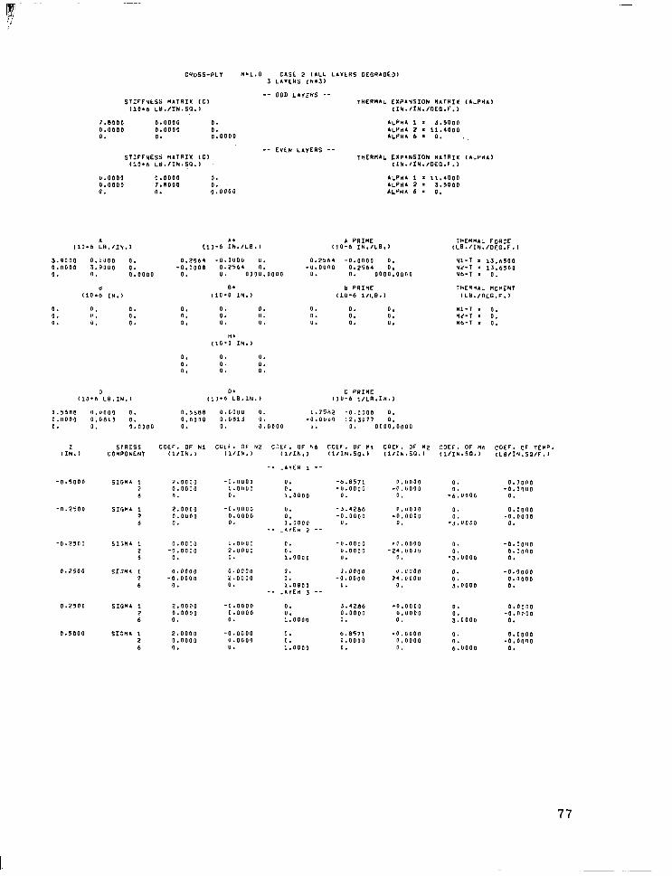
-
CQOSS.PLY l4=1.0 CASE 2 ,LLL LIILRS OEGQAOEJI 3 LL"E"S (h.3)
STIrFvtSS "ATRIX ,C, (10.b LLI.IIN.SG.1
-- ODD LA"E"S -- THER"AL EXPIYSION "ATRIM
,Ih./IN./GEG.F., ,ALP"I,
OliPdA,
7.800" 0.0000 0. .LPHA 1 = 3.5000 0.0000 0.0000 0. .LP"& 2 = 11.4000 1. 0. 0.0000 lLPH.6. 0.
-- FVSN _._ LAYERS -- STIFFHESS MATRIX (Cl THERMAL EXPrNSIOh MATRIX
(10.6 Ld.IIh.SP.1 IlN.IIh./OEG.F.,
U.0000 0.0000 a. ALPHA 1 = 11.4000 0.0000 7.11000 0. .LPHA 2 * 3.5000 0. I. 0.0000 ALP”* 6 = 0.
3.9000 Q.~uOQ 0. 0.7564 -Q.O"OO U. 0.2,(14 -0.0000 0. 0.0000 1.JOQQ 0. -0.0008 0.2504 0. .".O"IIO 0.2564 0. 0. 0. 0.0000 0. (I. 0000.0000 0. 0. 0000.0000
6 B* b FRIME (1016 IN.1 110-Q IN.) (10-b 1,LS.I
0. 0. 0. 0. L' . 0. 0. d. 0.
0. 0. 0. 0. 0. ". 0. 0. ".
H. , lO*Q IN.>
0. 0. 0. 111-T . 0. 0. 0. 0. ML-T . 0. ". 0. U. Mb-T * 0.
0. 0. 0. 0. 0. 0. 0. 0. 0.
A PRI"E (10-b IN.ILB,l
T"EN"AL FORCE ,LG.IIN./OEG.F,I 110.6 :B.m.,
HI-1 = 13.6500
;4-; - 1 = 13.6500 0.
ThERYAL NOMEHT (LO.IOEG.F.1
0 0. 0 PRIME (1Q.b LB.1H.I Ill-b LB.1N.J ,l"-6 l/LR.I*.)
n.55.5.5 0.1)00, 0. ".5588 O.OQQ" 0. 1.7582 -0.0300 0. 0.0000 0.0811 0. Q.QOQQ Q."dlJ 0. -0.0""" 12.3077 0. 0. 0. Q.QQOQ 0. 0. 0.0000 ". 0. 0000,000"
COEF. OF Nl Cut‘. OF 42 CSEF. OF Nb COEF. OF Nl COCF. ,F "2 COEF. OF Mb COEF. OC TEMD. (IIIN., ,lIlN.) (l/IN., (l/IN.SO., I1IIN.jO.I (lIIH.SO., ,LaIIN.SO/F.l
-_ .A"ER 1 -.
2 STRISS ,IN.l COnPOhEhT
-0.5000 SIG". 1 2 b
-".25QO SIGN. 1 2.0000 -0.0000 7 0.0000 0.0000 6 0. 0.
-0.2500 SI:". 1 0.0000 Q.Q”OQ 2 -0.0000 2.0000 1 0. 0.
0.2500 SI3N4 * O.QQQO 0.0000 2 -P.QOQO 2.0”“” 6 0. 0.
0.2500 SIGN& 1 2.0000 -0.0000 2 0.0000 0.0000 6 0. 0.
n.5000 SIGML 1 2 6
2.OO”Q 0.0000
-Q.Q”OQ 0. 0.0”“” 0. 0. 1.0000
0. 0. 1.0000
-_ -AvEH 2 --
0. 0. 1.0000
0. 0. 1.0900
-_ .A"E" 5 --
0. 0. l .QUOo
0. 0. l .QQQQ
-b.8571 -U.QQQO
F.11000 -0.11000
0.
-3.42.56 P."QOO -0.0000 -0.0000
". u.
0.
.::“oo,
0.
-k”QQo
Q.QQ~Q -0.0~""
0.
0.0000 -0.0000
0.
0.
-0.0000 .O.QQOO 0. ".QQ"Q -2~.QQo" 0. u. 0. -3.“UOQ
Q.0000 r~.oL7QQ 0. -0.UOQQ 24.00"" 0.
u. 0. 1.0000
-Q*QOQQ
::QQnQ
-0.0000
koQoo
2.0000 -o.aooo 0.0000 0.0000
3.4286 .O.OQQQ 0.0000 O."OQQ 0. 0.
0. 0. 3.0000
Q.QQ”O -Q.““QO
0.
.O.OUQQ 0. 0.0000 0.0000 0. -0.0010 D. b.“OOQ I*
6.8571 Q.QOQO
0. 0.
77
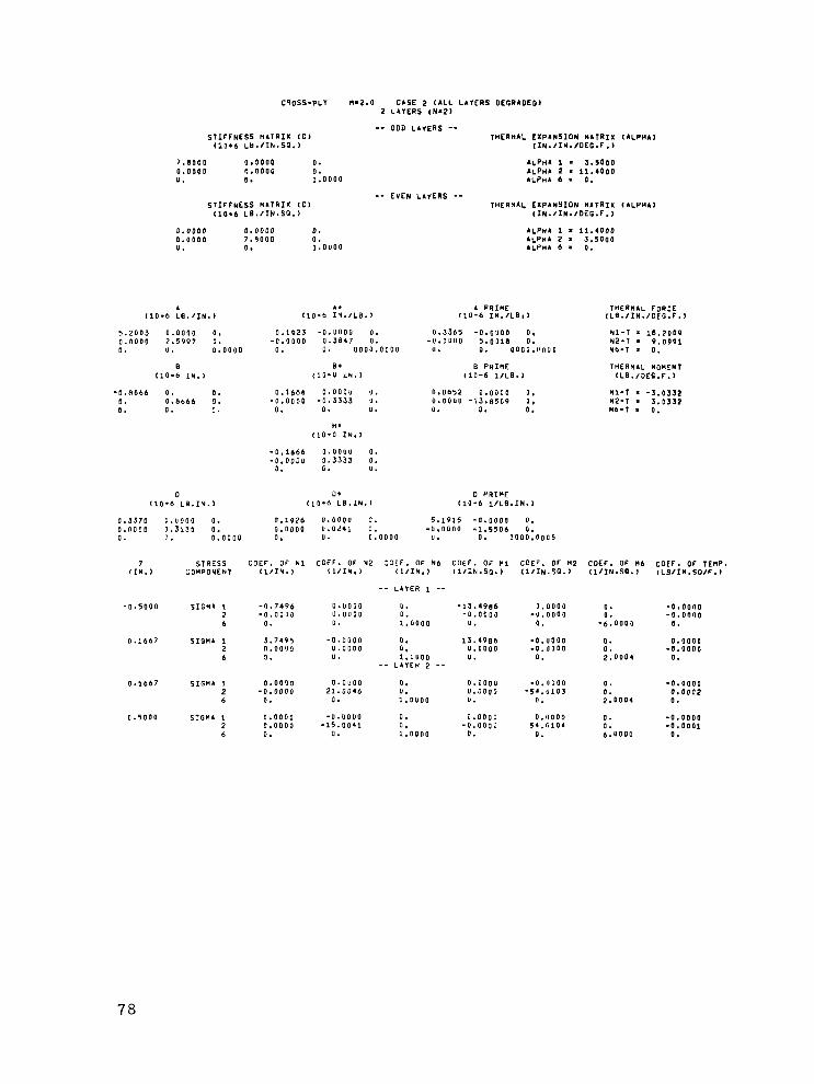
CQOSS.PLI "82.0 CASE 2 OILL LAYERS DEGRAOEG, 2 L&VCRS (N.2,
STIFFNESS MATRIX ICI (10.6 Lb.IIk.SG.1
-- ODD LAYERS -- THERIIAL EXPLNSION NATRIX ,ILPHA)
,Ih.IIN./OEG.F.,
7.8000 0.3000 0. ALPHI I = 3.5000 0.0000 n.0000 0. ALPHA 2 a 11.4000 0. 0. 0.0000 ALPhAb= 0.
STIFFNESS RATRIX ,C) (IO.6 LE./IN.SO.,
-- EVEN LAYERS -- IHERhAL EXPANSION "LTRIX (ALP"&,
,IN./IN./OEG.F.,
0.0000 0.0000 0. lLPh4 1 = 11.4000 Q.UQOO 7.9000 0. ALPHA 2 = 3.5000 u. 0. Q.OUOO Ai.PN)l 6 = 0.
110.6 :@.IIN.l 1. A PRIME
(10-b 1N.IL.S.) THERMAL F,R:E
(10-b Ih.,LB,, ,LB./IN.IOEG.F.,
0.1921 -0.U""" 0. -0.0000 0.3847 0.
0. 0. 0000.0000
8. (1"'" IN.1
0.3305 -O.c"OO 0. -".O""O 5.0018 0.
". 0. OOQQ.UOQQ
B PRIME (10-b l/LB.)
hl-1 = 18.2009 rip-1 . 9.0991 Yb-T = 0.
THERMAL "OhIN, ,L8./JEC.F.,
0.1666 Q.QQQU U. -0.0000 -0.5333 ".
0. 0. U.
R. flQ*U IN.1
0.8652 0.0000 0. 41-T * -3.0132 0.0000 -13.8509 0. az-I = S.0332 0. 0. 0. "b-T . 0.
-0.1666 Q."O"O 0. -O.QOQU 0.3333 0.
0. 0. 0.
5.2003 0.0000 0, Q."QOO 7.5997 0. 0. ". 0.0000
B 110.6 1h.j
-Q.Rbbb 0. 0. I. O.bbbb 3. 0. 0. I.
0 0. 0 PRIME (10-b L3.IY.j (10.6 LB.Lh., 110-b l/LB.IN.)
Q.SJ70 Q.QOQQ 0. 0.1926 Q.UOQO U. 5.1915 -0.0000 0. 0.0000 0.3130 0. 0.0000 II.0241 0. -".OO"O S1.5500 0. 0. 0.000" 0. u. 0.0000 U. 0. QOQ~:QQ05
7 STRESS c OEF. OF h1 , :OEF. OF Y2 :3if. OF Hb COEF. OF "1 COEF. OF M2 COEF. OF Mb COEF. OF TEMP. IIN.) COYPOYEht (l/IN., Il/Ih., l1IIH.l l1/1N.SP.1 ll/IN.SO., (lIIh.SO., tLBI1N.SOIF.l
-- LA"ER 1 --
0. 0. 1.0000
0. Q. l.UQQQ
-- LAIEH 2 --
-0.5000 fIGMa 1 2 6
0.1667 SIGN. 1 2 b
-0.74Pb -Q.Q030
0.
3.749s Q.QOQQ I.
“.“QQO U.QUQO u.
-0.0000 “.Q”QQ “*
-13.4986 0.0000 0. -0.0000 -O.QQQQ -u.oooo 0. -0.0000
u. 0. -6.0005 0.
13.4986 .O.OQQQ a. 0.0000 U.QQQQ -O.UQQO 0. -0.0000 u. Q. 2.0004 0.
0.1667 SIGMA 1 0.00"" 2 -0.0000 6 0.
0.01:“” Zl.UQ46
0.
0. 0.0000 -0.1,QOQ 0. -0.0000 0. ".QOQG -5,.(i103 0. O.OOQ2 1.0000 ". 0. 2.0004 0.
0.5000 SIGH1 1 Q.OQOQ -“.oooo 0. Q.QQQJ O."OOO 0. 2 0.0000 -15.00,1 0. -U."QQ3 5,.SlQ, 0. 6 0. 0. l.QQ”O 0. 0. b."QUQ
-0.0000 -0.0001
0.
78

ciloss-PLY “82.0 CASE 2 (ALL LAIEHS OEO?AOLOl I LAYERS ,N*3)
-- 000 LAviRS -- STIFFNESS H4TQIX (Cl THER'IAL EXPANSION MATRIX
(1O.b LLI.IIN.SO,I (IN./IN./OLC.C.,
7.8000 0.0000 3. ALPNA 1 = 3.5QOQ 0.0000 O.QQQO 3. .LPYA 2 a 11.4000 0. '0. ,.oooo ALP,,4 b = 0.
-- EVE" LAYERS -- STIFFNESS MATRIX (Cl THERMAL EXP*NSION MATRIX
(10.6 LB.IIh.SO.1 IIN./IY./OEG.F.,
,&LPWA,
(A.PHAl
0.0000 0.0000 0. ALPHA I = 11.400" U.0000 7.nooo 0. .LPHI 2 . 3.5000 0. 0. 0.0000 AL?nI b . 0.
. A. (10.6 LB./T’,., (10-b 1N.ILS.j
5.1999 0.0000 0. 0.1923 -O.OQUQ “. 0.0000 2.bQQl 0. -0.0000 0.Stl.b 0. 0. 0. 0.0”“” 0. 0. 0000.0000
I B. (IO*b IN., (lb*0 IN.1
0. 0. 0. 0. 0. 0. 0. 0. 0. 0. 0. 0. 0. 0. 0. 0. 0. 0.
I(* ,lQ’Q IN.1
0. 0. 0. 0. “. 0. 0. 0. u.
A PRIME (10-b 1h.ILE.l
THERMAL FoQCE lLO.IIh./OEE.F.~
U.1923 -Q.OQOO 0. .Ll.OO”O 0.344, 0.
0. 0. 0000.0000
Y PRIME (111-6 1,LS.b
hl-1 s 1.5.1998 hit-7 * 9.1002 Mb-7 ‘ 0.
THEN*AL “oMINT ,LII.,OCG.F.,
0. 0. 0. 0. 0. 0. ". 0. 0.
;;-; s -0.0000 - = -0.0000
“b-T . 0.
0 0. D PRIME tlO*b LI.IN.1 ,lO*b LB.II1.b (10-b ~/LB.IN.I
0.6259 0.0000 ". 0.6259 “.OllOO 0. I.5976 -Q.QOQO 0. 0.0000 0.02.1 0. 0.0000 0.0241 0. -O.““OG l 1.515I3 0. 0. 0. 0.0”“” 0. 0. 0.0000 0. 0. 0000.3005
2 STRESS COEF. OF Nl IIU.~ COMPONENT (1,111.)
COEF. OF "2 COEF. OF Yb COEF. OF "1 ,lIIN., (l/IN., I1IIN.SO.j
-- LATER 1 --
-0.0000 0, -6.2308 0.0000 0. -U.QQQO 0. 1.3000 u.
-Q."OQQ 0. -2.0770 O.UOQQ 0. ::0000
-".QQQO 0.
-- LAIER 2 --
COEF. Of H2 COEF. OF Ub COEF. OF TEMP. lllIN.50.) ,llIN.S0., fLBIIN.SGIF.)
-0.50""
-0.1667
-0.1667
Q.lbb7
0.1667
0.5000
SIGMA 1 1.5000 2 0.0000 6 0.
SIGMl I 1.50”” 2 0.0000 b 0.
0.0000 0. Q.“OOO -O.OUQQ 0. -0.0000
0. -b.“QUQ 0.
0.000" -0.0000
0.
0.
-;:“OUQ
O.QQ”O -Q.QQ”O
0.
SIONA 1 ".OOQQ U.Q”OO 0. -Q.QQQJ 2 -0.0000 2.YPYP 0. U.0000 6 0. 0. 1.0000 0.
SIWA 1 ".lOOO 2 -0.0000 b 0.
Q.QQUQ a. “.OOOO Z.PPYP 0. -u.oa~o 0. l,O#OQ u.
-- LAYER 3 --
-*.0000 -51.9577
0.
0.0000 53.9377
0.
0. -I."""0 0. Q.O"OO
-2.“O”Q 0.
0. -0.0000 0. O.QQ”O 2.“000 0.
SIGMA 1 1.5UQQ -Q.“QOU 0. Y.0710 -0.0000 2 ".OOOO 0.0000 0. Q.QQoJ 0.1000 b 0. 0. ~.O”OO “. 0.
SIGNA 1 1.5000 2 0.0000 b I.
0.
;:“ooQ
Q.0000 -0.0000
0.
0. O.QQQO 0. -0.0000 b.UOOQ 0.
-O."OOQ 0. b.230.5 -~.QQOQ 0.0000 0. Q.QOOO U.000" 0. l.QOOO 0. 0.
79

CHOSS-PLY f414.u CASE 2 ,.LL L.“ERS OEGS.DEO, 2 LAYERS ,N=21
STIrFNESS “ITRIX ,C, (10.6 1B.IIN.SO.l
7.UQQQ 0.000” 0. U.5100 0.0000 3. u. 0. j.0000
STIFFNESS H.TRIX (Cl (10.6 LB.IIN.SO.1
0.0000 0.0000 0. 0.0000 7.8000 0. 0. 0. 0.000"
A A. (10.6 LL(.,IN., ,10-b IN./Ltl. 1
-- 000 LAYERS -- 1HERH.b EXP.tdSIOh MATRIX
(1N.IIN.IDEG.F.l
.LP”. 1 i 3.5000 *VHC 2 = 11.4000 ALPHI 6 i 0.
EYE” LIIERS -- ,HERM.L EXPINSION H.,RIX
,IN.IlU./OEG.F.)
.LPH. I = 11.4000
.LPH. 2 i 3.5000 4LPH.b. 0.
A PRIME ~10-0 IN.ILG.1
6.2400 0.b”“” 0. 0.1603 -0.0000 0. ".I903 -0.0JQQ 0. 0.0000 1.56r10 II. -Q.OQOO U.641” 0. -O.U”QLI Jl.rQB” 0. 0. 0. 0.0000 0. 0. “0,“.0000 “. 0. 0000.0000
8 E. L1O.b I"., (10.0 IN.1
-0.6240 0. 0. 0.1300 0."""" 0. 0. Q.b?.-, 0. -".QOQO -0.4""" 0. n. 0. 3. 0. 0. 0.
H. (10." IN.)
-0.1000 Q.“QOO 0. -0;QiQQ U.4000 0.
0. 0. “.
0 0. (111.6 LG.IU.) il3.b LB.IN.1
0.3352 0.0001 0. Q.JI2.3 0.0000 0. Q.00”” 0.2549 3. Q.QJQQ 0.0052 0. 0. 0. 0.0000 0. 0. 0.0000
B PRI”E (10-b 1,LG,,
“.S”b5 0.0300 0. U.0000 -76.9194 0. 0. 0. 0.
0 PRIME (10-b ~ILB.IY.,
J.QU.38 -Q."iQ" 0. -“.O”OU 102.2987 0.
“. 0. QOQO.OOU5
,.LPl+.,
LILP”.,
THEI*.L FORCE ,LB./IN./OEG.F.,
Vl-T = 21.R4QQ Nz-, = 5.4500 ND-, * 0.
,~E”Y.L MOMINT tLH./QEG.F.,
Ml-T . -2.1340 viz-, = 2.1840 *b-T = 0.
I STRESS C3EF. OF Nl COEF. DF 12 COEF . “F hb ‘OEF. OF Nl COEF. OF H2 COEF. OF M6 COEF. OF TEMP. ,IN., C’IIIDONENT ,l,Ih., (I~IN.~ ,l/Ik., (lllk.SO., ,l,lN.SO.l ,lIIN.SG.) ,LB/IY.SOIF.~
-- L.YER 1 -.
-0.5000 SIGM. 1 0.3175 -".QQoo "* 2 0.0""" 0.0001 0. 0 0. 0. 1.0000
-9.3750 O.“QQQ 0. -l.QQQO -0.00”” -0.0002 0. -O.QQQO
0. (I. -6,“005 0.
1.3000 SIGH. 1 1.1875 -0.0000 0. 9.3753 -0.11000 0. Q.Q”OQ 9 O.0”“” 0.“““” “. b.0003 -0.0000 0. -0.000” 3 “. 0. 1.0000 u. 0. 3.6006 n.
-- L.“ER 2 --
0.3000 SIGMA 1 F.000” 0.0000 0. 7 -0.000” b4*YP70 0. b 0. u. 1.0”“”
0.5000 SIGH. i 0.0000 -o.""oQ 0. 7 Q.QQQO -54.9973 0. 6 0. "* 1.0000
Q.QQJJ -0.11000 0. -Q.“OQO “.OOQl -149.9926 0. “. F. 3.t.000 ::QQQ5
“.QQQQ 0.0000 0. -0.00”” -“.QQo” 149.993) 0. -0.0004
u. 0. b.“OQG 0.
80
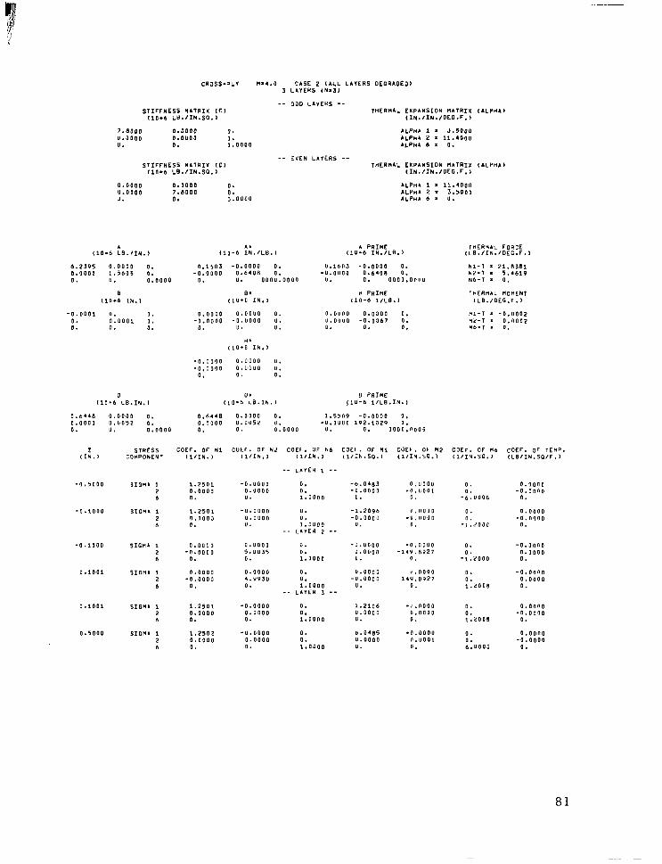
CRJSS.?L” N.4.Q CASE 2 (ALL L.“E”S DEGR.DEJl 3 L.“E”S ,H.3,
-- 000 L.“EHS -- SIIFFNESS “.,RIX ,C, ,HER”.L EXPINSION “ATRIX
(10.6 LY.IIN.SG.1 ,IN./Ih./OEG.F.,
7.8000 0.0000 0. .‘PH. 1 = J.5DOO ".QQOO I.Q"QO 0. u. 0. 0.0000 y: ; 1
11.4oou 0.
STIFFNESS “ATRIX ,C, (10.6 L8.IIN.SO.I
_- <“EN L.“ERs -- THER”.L EXPANSION MATRIX
,IN.,IN.,“EG.F.,
ILPH. 1 = 11.4000 .LPH. 2 * 3.5Q”Q .LP,,. b i 0.
I.LPII..)
,.LP”.)
0.0000 0.0000 0. U.0000 ?.BOQQ 0. J. 0. 0.0000
.I . PRIME T”ER*.L FOR:E (10-b IN.ILS.) (10-b IN.ILB.1 ,LS.IIN.IOEG.F., (10.6 :S.,Ih.,
6.2195 0.0000 0. 0.1503 -0.0000 0. O.QQ"Q 1.5605 0. -0.0000 0.6408 0. 0. ". 0.0000 0. u. OOO".OQQQ
".lb"S -0.0000 0. 21.L3.51 -".O""O 0.640" 0. w; : 5.4619
". 0. OOQO.O"UQ NO-, . 0.
tl PRIME TnERll.L MOMENT tl"-b 1,LB.l (LS./QEG.F.I
B Be (lo*6 IN., cl"*" IN.,
-0.0001 0. 0. Q.QQQQ 0.00"" 0. 0. Q."QQl 0. ‘0.000" -0."000 u. 0. 0. 0. 0. ". 0.
". ,lUfQ IN.)
-0.0300 0.""00 ".
0.0~00 0.0000 0. “1-T = -0.0002 “.O”IIQ -0.0367 Q. "L-T i O."QQ2 ". 0. 0. *b-T s 0.
-Q.QQOO “.“Q”” U. 0. 0. 0.
0 PRIME ,1"-6 1ILG.IN.l
1.5509 -0.0000 0. -".O""Q l"2.1320 ".
". 0. OUOU.11005
0 01 (10-b LS.IN., (10.6 LB.IN.,
Q .6.41 0.0000 0, 0.0448 0.0000 0. 0.000” 0.“05? 0. 0.“““” 0.““52 “. 0. u. Q,OOOO 0. 0. U.0000
COEF. OF H2 CQEF. OF Mb (lIIN.SO., (1IIN.SG.I
z STRESS CUEF. OF HI (IN.) COMPONENT (l/IN. 1
C”Ef . OF N2 COEF. OF kb COEb . OF Hi (l/IN., (l/IN., ,l/IN.SO.,
-- LA”EH 1 --
-0.5000
-Q.lQOQ
-0.1000
0.1001
0.1001
0.5000
COEF. OF TE”P. ,LSIIh.SO/F.)
jIGI I 1.2501 2 0.0000 b 0.
-U."QQQ 0. -6.0483 Q."QOQ 0. -".QQQO 0. 1.0000 u.
-"."QQQ ". -1.2096 O."QQO
1":QQQo -0.0000
0. ". -- LA"EH 2 --
"."OQO 0. -"."DQQ 5.""35 0. ".QOQQ 0. 1.000" u.
0.0000 0. ".UQQO 4.YYS" 0. -“.UOQQ 0. 1.0000 “.
-- L.“ER 3 --
Q.“QQU -O.“QQ,
0.
6.“““” -Q.“QO”
0.
0.
-::“oo,
0. “.
-l.dOUC
0.0000 -Q.Q""O
".
0.000" -O."l"Q
0.
SIGMA 1 1.2501 2 Q."OOJ 6 0.
-0.0000 -14'3.8927
0.
l '."QOO 14Y.8327
0.
-0.00"~ Q.QQOO 0.
SIGN. 1 0.0003 2 -O.QUQO 6 0.
3.10". 1 0.0000 2 -0.000” 6 0.
0.
-~:2000
0. 0. l&009
-0.00"" 0.0000 0.
SIGMA I 1.250, -0.0000 0. 1.2lQ.5 -~~."Qoo 2 Q.QUOQ 0.0000 0. ".QQQC 0.0000 b 0. a. 1.00"" u. 0.
0.
::zou9
0.00"" -Q.QQ"O
0.
SIGMA 1 1.2502 -"."ooo 0. b.04.35 .0.0000 0. O.OQ"O 2 0.0""" 0.0000 0. ".QOQQ 0.~001 0. -Q.QQOO 6 0. 0. 1,QUOO ". 0. 6."""~ 0.
81
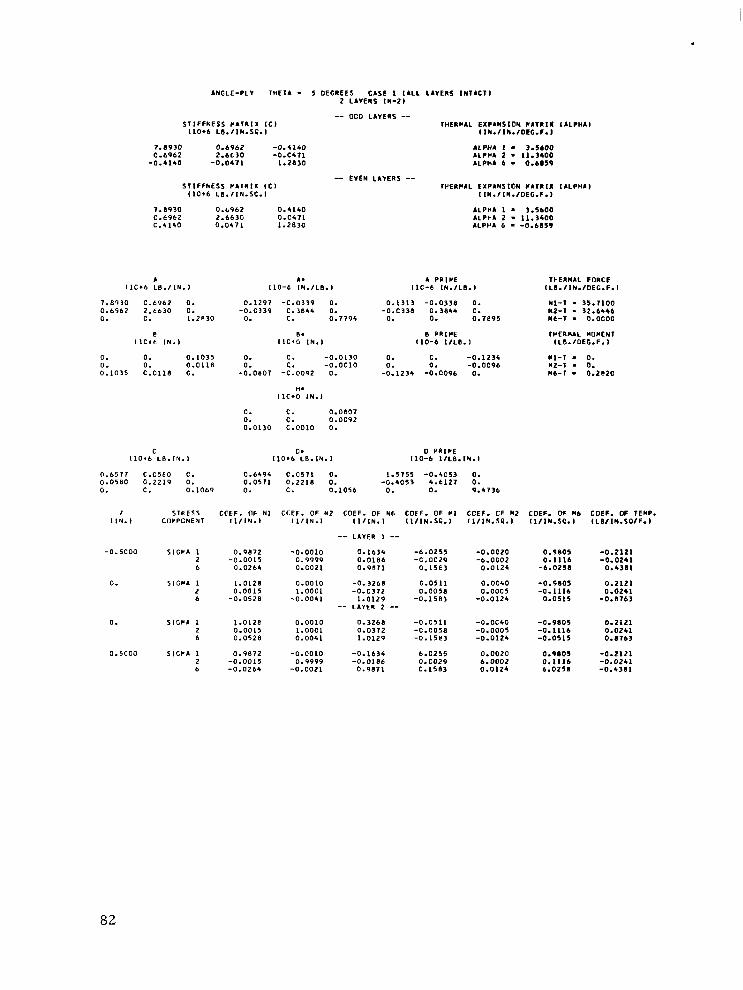
.
ANGLE-PLY THE,. - 5 OEGIEES CASE I (ILL LllElS ,N,lC,, 2 LAYERS IN.2,
-- 000 LA”E”S -- STIFFNESS P.TR,X ICI WERLAL EXPANSION CATIIX IALPHA
,10*6 L6./IN.SC.I IIN./IW.IOEG.F.~
7.6930 0.6962 -0.4140 ALPHl I - 3.5600 C-6962 2.6630 -0.CS71 ALPHA 2 - 11.3400
-0.4140 -0.0471 1.2830 .LPWA 6 . o.Las9
-- EVEN LAIERS -- STlFFkESS CATRlX ,C, WEWIL EXPANStON C.,“,I ,.LPHA,
(IO+6 LE.fIN.SC.1 IIN.fIII./OEG.F.)
1.11930 0.6962 0.4140 .LPH. 1 = 3.5600 c.cqt.2 2.663G O.C&,, ALPI.). 2 - 11.3400 C.G,SO 0.0471 1.2830 ALPPA 6 - -0.68SV
L A. A PIIIPE TPERMCL FORCE ,lC*I LB.,,N.I 110-t IN.ILO.I IIC-b [N./LO. I ,LO.IIN.IOEG.F.I
I.B’)30 C.6962 0. 0.6962 2.t630 0. 0. C. 1.2R30
E IlCte IN.,
0.1297 -c.o339 0. -0.0339 C.3844 0.
0. c. 0.1795
R. ,lC+G IN.,
0.,313 -0.0336 0. -0.C338
O- 0. ::‘a” 0.7895
E PRIPE 110-6 l/LB.1
Nl-, . 35.1100 NZ-1 - 32.6446 N6-T - o.ocoo
TVERM.L “OMEN, 1LB.IOEG.F.i
0. 0. 0.1035 0. 0. 0.0118 0.1035 C.Cl1.3 C.
0. 0. -0.0130 0. C. -0.0c10
-0.0807 -C.0092 0.
H. IIC*O ,N.,
0. c. -0.1234 0. 0. -0.0096
-0.1234 -0.0096 0.
“1-I - 0. “2-T * 0. 116-T - 0.2120
0. c. o.oeo7 0. C. 0.0092 0.0130 c.0010 0.
C I1016 L6.IN.I
0 PRlPE 1,0-b IIL6.lN.I
0.6571 c.c5eo c. 0.0580 0.2219 0. 0. C. 0.1069
0. (1011 LB.1N.l
0.6494 c.057, 0. 0.0511 0.221.S 0. 0. c. 0.1056
1.5755 -0.4053 0. -0.5os3 5.6127 0.
0. 0. 9.4736
1 STRESS CPEF. OF Nl CCEF. OF N2 COEF. OF N6 COEF. OF P, CCEF. CF 112 COEF. OF "6 COEF. OF ,E”P. IIN. COPPCNENT ,,,,N., IIIIN.l 11IIN.I l lIIN.SO.1 ll/IN.S’J.I l111N.SQ.1 iLBI,N.SQIF.l
-- LAYER I --
0.1635 o.oln6 0.9871
-0.3266 -0.0372
1.0129 -- LA"ER 2 --
-6.0255 -c.o029
0.1563
0.051, 0.0050
-0.1563
0.3268 -0.c511 0.0372 -0.0058 1.0129 -0.15e3
-0.5000 SIGPA 1 2 L
0. SIGNA 1 2 6
0.9672 -0.0010 -0.0015 0.9999
0.0264 o.co2,
-0.0020 -t..ooo2
0.0124
0.0040 0.0005
-0.0124
0.9805 -0.2121 0.1116 -O.OZll
-6.02¶1 0.4361
-0.9805 0.2121 -0.1116 O.OZll
0.0515 -0.1163
I.0126 0.0015
-0.0528
0.0010 1.0001
-o.oo,*
0. SIGPA I 2 6
0.5too SIGPA 1 2 6
1.0128 0.00,s 0.0528
0.9672 -0.0015 -0.0264
o.oo,o 1.0001 0.0041
-0.0010 0.9999
-0.0021
-0.OC60 -0.000s -0.0124
-0.9803 0.2121 -0.1116 0.02~1 -0.0515 0.6763
-0.1634 6.0255 0.0020 0.9805 -0.2121 -0.01116 O.CO29 6.0002 0.1116 -o.oz*,
0.9171 0.15.93 0.0124 6.02SB -0.4381
82

ANGLE-CL” THE,. - 5 DEGREES CASE 1 ,.LL LLIERS ILllbC71 3 L.“ERS IN.31
-- 000 LA”E”S -- SVIFFNESS P.,LIX ,C, 7HERM.L EXCANSION C.,l,l
IlOW LI./IN.SC. t IIN./IN./DEG.F.J
7.8930 0.6962 -0.4140 .LPH. I - 3.5600 0.6962 2.6630 -O.C,,l LLPHA 2 - 11.3600
-0.4140 -0.0511 1.2630 ILCH. 6 . 0.6119
-- FYFN L,“ElS -- TREII~.L EXPANSION PIT”,,,
lIW.fIN.IOEG.F.~
_._ STIFFLESS l IIRIX ICI
1,016 LI./IN.SC.)
1.6930 0.6962 0.4140 O-b962 2.6b30 o.c471 0.4140 0.0471 L-2630
.LCHl 1 . 3.5600 ALIP& 2 - *,.,.co ALIMA 6 . -0.6659
A 1. 1 PRIPE TPElllllL FORCE llOI6 LB.,IN., IlO- IN.ILB.1 I LO-6 IN-/LO. I ILB.IIN.IOEG.F.1
7.1930 0.6962 -0.1379 0.1299 -0.0339 0.0136 0.1299 -0.0339 0.0136 0.6962 2.6630 -0.0157 -0.0339 C.3644 o.oc11 -0.0339 0.3154 G.0011
-0.1379 -O.CISl 1.2630 0.013b 0.0011 0.7EO9 0.01,6 0.0011 0.7809
I II- E WIPE I1016 IN., IlO+ IN.1 .iIO-b IILB.,
N,-r - 3S.llOC 112-T - 32.b546 Nb-7 - -0.3751
0. 0. 0. 0. 0. 0. 0. 0. 0.
0. 0. 0. 0. C. 0. 0. C. 0.
H. t1c.o 111.1
0. C. 0. 0. C. 0. 0. a. 0.
0. 0. 0. 0. 0. 0. 0. 0. C.
MI-T . -0.0000 *z-7 - -0.0000 Lb-l - 0.
c 0. C PlllPE IlO* LC.1N.I ,lO*b LB.1N.I 110-6 IILB.,N.,
0.6577 0.05no -0.0319 0.0580 0.2219 -0.0036
-0.0319 -0.CO36 0.1069
0.6511 c.o,no -0.0319 0.0510 c.2219 -0.OC3b
-0.0319 -0.003b 0.LOb.P
1.5103 -0.4051 O.kS71 -O.kOSl 4.6121 0.03S7
0.4578 0.0357 P.W,l
1 STRESS COEF. OF Nl COEF. OF N2 COEF. OF N6 CCEF. OF Cl COEF. OF r2 CCEC. OC Pb COEF. OF 7E”P. (IN., COMPCNENI 1111N.l IlI1N.I I1,IN.l IlIIN.SE.~ II/lh.SO.l l,/lN.SQ.l ILBllN.SOIF.1
-- LAlER L --
-0.5000
-0. ,667
.-0.16b7
0.1661
0.1667
o.scoc
SIWA 1 2 6
SIG*. 1 2 6
0.9963 -0.0003 -0.2156 -5.9930 0.0005 0. ,456 -0.0621 -0.0005 1.0000 -0.0255 o.ooon -5.9999 O.Olbb -0.0071 -0.0358 -0.0027 0.9962 Cl.0235 0.0018 -5.9929 -0.57no
0.9963 -0.0003 -0.2156 -1.9981 0.0002 0.04n5 -0.0621 -0.000~ 1.0000 -0.0245 0.0003 -2.0004 0.0055 -0.0071 -0.03411 -0.0027 0.9962 0.007B O.OCO6 -,.PPno -0.5110
-- LA”E” 2 --
SIG". 1 2 6
SIGN. I 2 6
1.0075 O.OOOP 0.0696
I.0015 O.OOCP O.ObPb
0.000b 1.0001 0.0054
0.000b 1.000, 0.005,
0.5310 0.0690 1.0075
-2.0b12 -0.0069 -0.2036
0.1212 O.O,,l 1.1556
0.4310 0.0590 1.0075
LA”El 3 --
2.0612 0.0069 0.2036
-o.oo,n -2.0009 -O.OlSP
0.001.3 2.0009 0.0159
-1.2615 -0.1435 -2.0616
L.2615 0.1.35 2.0616
0.1242 0.0,s* ,.15S6
SIGPA 1 2 6
-0.oco2 -0.0405 -O.ObZ, 2.0004 -0.0055 -0.001,
-0.0006 1.9980 -0.5780
SIGCI 1 2 b
0.9961 -0.000. -0.0351
0.9963 -0.0004 -0.0346
-0.0003 1.0000
-0.0027
-0.0003 1.0000
-0.0027
-0.2156 -0.0255
0.9962
-0.2156 -0.0245
0.9962
I.9961 -0.0003 -0.0078
5.9930 -0.ooon -0.0235
-0.0005 -0.1496 -0.062, 5.9999 -0.0166 -0.0011
-0.0016 5.9929 -0.57no
83

ANGLE-PL” THETA . 10 DEGREES CASE 1 IlLL LAYERS INTACT, 2 LAYEllS lk.2,
-- 000 LllElS -- STIFFNESS CAlRIX ICI TWERPAL EXPANSION *.,“,I lbLPV4.I
110.6 LB./IN.SC., I,N./16./OEG.F.)
7.66CO 0.7693 -0.1989 0.7893 2.6900 -0.1093
-0.7989 -0.1093 1.3760
-- EYEN Ll”ERS -- STIFFNESS CATRIX ,C, IHEIPAL EXPlhSlON l lrll,l IALPHA,
(10.6 LE./IN.SC.I IIPi.llh./CEG.F.I
l.6600 0.7893 0.7969 lLP”l I = 3.7362 C.7893 2.6900 0.1093 LLPP. 2 - 11.1620 0.19R9 0.1093 1.3760 ALPhA 6 = -1.3510
c A. A PPIPE WER”.L FORCE IlC*I LP.IIN.1 110-b 1N.ILB.I ,lC-6 IN.ILB.1 ILB.I,N.fOEG.F.l
1.6800 0.7693 0. 0.1893 2.69CO 0. c. C. 1.3160
e t1C.b IN.,
0. 0. 0.1997 0. c. 0.027, 0.1997 C.0273 0.
0.0257 C.0026 0.
0. 110.6 LR.1N.l
C PF!,PE 110-b 1,LB.IN.I
C.640C C.CC58 0. O.bl,C C.Obll) 0. ,.Le,, -0.4654 C. 0.0658 c.2242 0. O.CblU C.2236 0. -0.665, 5.6004 0. 0. C. 0.1157 0. C. O.lC-35 0. 0. 9.1362
0.,343 -c.o,95 0. -0.0,95 0.3633 0.
0. C. 0.72.57
6. ,,c*o IN.,
0. 0. -0.0257 0. C. -0.OC26
-0.145, -c.o,w 0.
Ii. IlC.0 led.,
0. C. 0.1451 0. G. 0.0199
2 STRESS ‘OEF. OF Hl CCEE. OF N2 COEF. OF Nb (IN.1 CO*PC*FST IlIlY., l1IlN.l ,,,,N.l
-0.5000 SIGPA 1 0.9530 -0.CO48 2 -0.0065 0.9993 b 0.05,9 0.0055
0. SIGPl I ,.OG,C O.POSB 2 0.0064 1.0001 6 -O.lClS -0.0109
0.1403 -o.o,nn 0. -0.03LIB 0.3835 0.
0. 0. 0.7613
6 PYIPE (LO-6 1ILC.l
0. 0. -0.2351 PI-, . o.ococ 0. 0. -0.0238 *2-r . 0.
-0.235, -0.0236 0. 116-T I O-S669
-- LLIER 1 --
0.3041 O.OC16 0.9514
-0.6062 -0.ot132
1.0416 -- LIIER 2 --
0. SIGPA 1 L.057C o.co+n O.bOb2 -o.,n79 -0.OIPC -I.CZ,, 0.7966 2 0.0064 l.COOl 0.0832 -c.o257 -O.OCZb -C.2596 0. LO9C b 0.1075 O.ClO9 1.0416 -C.32,6 -0.0,28 -0.19cs 1.8295
0.5ooc SIGP. , 0.953c -0.co4n -0.3051 &.CP39 0.0095 ,.P247 -0.7966 2 -0.0064 0.999, -0.0616 C-C,29 L.GOl3 C.2596 -0.1090 0 -0.0535 -O.COSS 0.9524 C-3236 O.O,ZB 6.C952 -0.91.1
CCEF. OF Cl Ill1N.SO.l
.
-b.O939 -0.0095 1.62~7 -0.7966 -0.0129 -6.0013 O.Z*Pb -0.109c
C.1236 0.0326 -6.CPS2 0.914,
C.,Bl’) 0.0190 -1.82hl 0.1966 0.0257 O.OC26 -0.2496 0.109c
-C.,136 -0.0328 O.,PC5 -1.8295
N,-1 . ,6.,,02 NZ-7 * 32.8267 Nb-T - o.ococ
7HEIIW.L HOMEN~ 1LR.IOEG.F.I
CCEF. CF *I CGEF. OF Cb COEF. CF TECP. tI/lh.sa.t l,/IN.SO.I ILB,IN.SO,F.,
84

ANGLE-PLY lHE,L * IO DEGREES ClSE 1 (ALL LllERS INT.‘,, 0 3 LIlElS IN-31
STIFFNESS P.,R,X ,C, llC+b L6.IIN.SC.I
l.LBCO O.lbP3 -0. ,989 c.1.393 2.69CO -0.1093
-c. 7989 -0.IC93 1.3760
SIIFFNESS PArRIll ICI IIC+b LR.IIH.SC.,
-- ““0 ‘,.“EIS -- VPERPAL EXPAhSlCN CA,R,x ,ALP,u,
,IN.,,h.,OEG.F.,
.LPHA 1 . 3.1362 ALP”. 2 - l,.lbZO .LPkA 6 * 1.3SlO
-- EVEN LAYERS -- IHERPAL EXP.hSl”N C.,l,X ,.L,WA,
,Ih.,,k.,CEG.F.,
1.6(100 0.7893 0.19E9 .LPCl I . 3.7312 C-7893 2.6900 0. ,093 ILPhl 2 = 11.1620 0.7989 O.IOY, 1.376C .LF’hA 6 - -1.3510
d 110.6 L0.llN.l
1.6800 0.1193 -0.2662 O.lll93 2.69CO -0.0364
-0.ZL02 -C.O364 1.3760
B ,lCIb IN.1
0. C. II. 0. C. 0. 0. C. 0.
I. 110-b 1N.ILB.I
A PRIPE ICERP.L FORCE (10-L IN.IL.3.I ILC.,IN.,OEG.F.,
0.1351 -C.O’93 0.025, Nl-, - 36.4402 -0.0393 0.3833 o.oc25 NZ-7 . 32.(1211
c.c25* 0.0025 C.1317 Nb-, - -0.1122
B PRIPE 7I-ERM&L PCWIII IIC-b 1,LC.I ,LB.,DEG.F.,
0. 0. 0. 0. 0. 0. 0. 0. 0.
*1-r * -O.cOOC 112-r - -0.0000 Lb-, . 0.0000
0. ,351 -c.o393 0.025, -0.0393 C.3833 o.oczs
0.0251 c.0025 0.7317
8. ,,O+O IN.,
0. C. 0. 0. c. 0. 0. C. 0.
C. IIC+O IN.,
0. C. 0. 0. c. 0. 0. 0. 0.
c IlO. LR.IY.1
0.6600 C.CbSB -0.Cb.16 0.06.58 c.2242 -0.COR4
-C.O‘,b -C-C084 0.114,
0. IlO. LO.IN.,
0.6*00 C.OL5.8 -0.0616 O.CbSb c.2242 -0.ocB5
-0.Cbl‘ -c.cons O.l,Sl
C PRICE IIC-6 IILB.lN.1
1 STRESS COEF. OF N, CCEF. OF N2 COEF. OF N6 CCEF. CF PI ,,%.I COPPCNEH, ,,,IN.I IlIIN., ,l,,N., ,lllh.SC.I
CCEF. CF HZ CCEF. OF Pb COEF. OF TEMP. 1,IIN.SO.I ~1IIN.SC.I ,LRIIN.SO,F.,
-- LlYEl I --
-0.3698 -0.0533
0.9864
-0.3898 -0.0533
-o.‘,coo SIGPl I 0.9166 2 -0.0018 b -0.0191
-0.,tt1 SIWb 1 2 b
0.9”bb -o.oo,n -0.069,
-o.c0,4 0.9998
-0.0070
-0.0014 0.9')98
-0.0070
-5.9740 0.0026 0.2773 -0.2266 O.CO36 -5.9996 o.c313 -0.0310 C.01183 O.OC,P -5.513, -I.,123
0.9865 -- L/“ER 2 -_
-l.PP,I 0.0009 O.C9CE -0.226e C.COIZ -2.0003 O.C,24 -0.03,o C.OL61 C.OClb -1.5916 -1.1123
0.7793 -2.2253 0. ,066 -0.0306 1.0211 -0.4184
-2.3593 0.4535 -C.3226 0.0620 -2.2265 2.34*0
0.1793 O.lOb6 1.021,
-- LIlER 3 --
-0.3898 -".0533
0.9864
2.2253 0.0308 C.5154
-0.0228 -2.oc35 -0.0424
0.0229 2.0035 0.042,
2.3593 0.5S35 C.3226 0.0620 2.2284 2.3,,0
1.9911 -0.0009 -0.CW.3 -0.2260 -c.oo,z 2.oco3 -0.c124 -0.0310 -0.0161 -0.0016 I.5916 -1.1723
-0.3898 -0.0533
0.9864
5.9740 -0.0026 -0.2723 -0.2268 -C.CO’b 5.9996 -0.c373 -0.0310 -0.0583 -0.0049 5.9137 -1.1723
-0. ,661 SIG*). 1 2 6
0. Lbb, SIG*. 1 2 6
1.0267 0.0037 0.1382
1.0267 0.0037 0.1362
0.002, 1.0004 0.0*40
0.002, 1.0004 O.Ol40
O.lbb, SIC*. 1 2 6
o.scoc SIG** 1 2 6
0.9866 -o.oo,n -0.069,
0.9866 -0.0011 -0.0691
-0.0016 0.9998
-0.0070
-0.00,s 0.9998
-0.0070
85
ANGLE-PLY THE,. . 15 DEGREES C&SE 1 (ILL LIVERS IN76C7l 2 LLVERS IN-21
SIIFFNESS CIIRII ICI IlCIb L8.IIN.SC.i
-- 000 LllERS -- ,HEI”.L EXPLICSION PAIR11
,IN./,k.fOEt.F.l
ALPHA 1 . 4.0292 .LPH. 2 - 10.6700 ALPH. 6 . 1.97so
7.3420 0.9320 -1.1290 c.9320 2.7430 -0.1993
-1.1290 -0.1993 I.5190
SllFFNESS PL,R,I (Cl (IO*6 L0.lIN.SO.l
7.3420 0.9320 1.1290 0.9320 2.1430 0.1993 1.1290 0.1993 1.5190
A I. I1016 L8.IIN.l 110-t ,N.,LB.,
EVEN LIVERS -- lHERCI6L EXP.NS,OI( 1611111
l,N./,h./OEG.F.I
ALP”. 1 . 4.0292 .LPH. 2 - ,0.n700 ALPHA 6 - -1.9750
,ILPHAl
(ALPHA1
1 PlllPL I IC-b ,N.,LE. I
7CERII.L FORCE IL6.,,N.,OEG.F.,
7.3420 C.9320 0. 0.1423 -c.o4n* 0. 0.1541 -0.0466 0. 0.932C 2.1530 0. -0.0184 C.3610 0. -0.0466 0.3612 0. 0. c. 1.5190 0. G. 0.658’ 0. 0. c.1205
e R. B PllPE l,Ctb IN.1 lIEI IN., 110-b 1fLE.I
0. C. 0.2922 0. C. -0.0318 0. C. -0.3265 0. 0. o.o,w 0. 0. -0.0053 0. -0.0461 @.2t!22 o.c49n 0. -0.1esLl -C.O326 0. -0.3265 -Lb, 0.
*. IlC*O IN.,
0. C. o.,esn 0. C. 0.0321 0.0378 0.0053 0.
C C= c PPICC 110.6 LO-IN.) 1,016 LB.1N.I 110-6 IILI.1N.I
O.blle c.0711 0. 0.5594 c.ote4 0. 1.8Sbl -C.5595 C. 0.0771 C.2216 0. O.CbE.4 E.2269 0. -0.559s 4.5769 c. 0. C. 0.1266 0. C. 0.1157 0. 0. 1.6462
I STRESS COEF. OF 111 CCEF. OF HZ COEF. CF Nb CCEF. CF Cl CCEF. CF P2 CCEF. OF P6 COEF. CF TEMP. l1N.t COPPCNENT I1IIN.I II/IN.1 I1fIN.l I1l1k.SC.1 Il~lk.SO.I l11111.50.1 IL8IIN.SOlF.I
-0.5c00 SItmA 1 0.9cie 2 -0.0163 6 0.0621
-- LLlEll 1 --
-0.c130 O.,C67 -b.1853 -0.0260 0.9911 0.0716 -C-C325 -6.0056 O.Ol,l 0.9055 0.696.0 0.0700
0. SIGPA 1 1.0922 O.O,‘O -0.1135 0.3687 0.0521 2 0.0163 1.002’ -0.1436 O.tb5, O.OC92 b -0.1653 -0.023’ 1.0945 -0.4960 -0.0700
-- LlrEll 2 --
-2.4504 1.6191 -0.4306 0.2859
0.3116 -2.9656
0. SIGPA I 1.0922 O.Cl30 0.113s -C.3667 -0.0521 -2.4401 l.bl91 2 0.0163 1.0023 0.14jb -0.065, -0.0092 -0.6300 0.2e59 b 0.1653 U.0233 I.0945 -0.4960 -0.070c -0.3176 2.9C56
0.5000 SIGPA I 0.9076 -0.c130 -0.5Cbl 6.1843 0.0260 2.4504 -1.6197 2 -0.0163 c.9971 -0.071e 0.0325 6.0046 0.4306 -0.2e59 6 -0.0627 -0.0111 0.9055 0.49bG 0.0100 6.1089 -1.5528
111-l - 37.563s NZ-T . 33.1160 116-V . 0.
,CELIPIL “CMtN7 IL6.IOEG.F.l
II,-, . 0.0000 “Z-1 - 0.0000 #6-7 . 0.928C
2.4404 -1.6191 0.4306 -0.zn59
-6.1889 I.4520
86

AYGLE-PL” ,HE,. . IS DEGREES USE I IILL LIVERS INlACll 3 Ll”E”S 1N.3,
STIFFNESS “6T”lX (Cl 110.6 Ll.,,N.SO.,
1.3,20 0.9320 -1.1290 0.9320 2.1.30 -0.,993
-I.,290 -0.1993 l.S190
-- 000 LAlElS -- WEIIIIL EIPAhSlON “11.11
1111.11N~f0EG.F.l
ALPI 1 - k.0292 ALPNA 2 . 10.#100 CLWII * - 1.9150
-- EVEN LAIEIS --
l6LPHIB
lILPH.1 STIFFNESS CIrllX ICI THER”IL EXPAkSIOY “1,111 (1016 LI.IIN.SO.I l1N.IIW.IOEG.F.~
1.3,20 0.9320 I.1290 .LPN. 1 . ,.0292 0.9320 2.7,30 0. ,993 ALPHI 2 . ,0.Ll700 1.1290 0.1993 1.5190 ALYH. b . -1.Pl50
1 A. A PYlFE TkEIIIIIL FORCE llO.6 L6.IIN.I 110-6 1N.ILI.l 110-b ,N.,LB., ILI.IIh.IOEC.F.I
0. ,+*c -0.0461 0.0336 -0.0481 0.3110 O.OO,l
0.0336 0.0041 0.6666
B. 410.0 IN.,
1.3,zc 0.9’20 -0.3lb2 0.9320 2.7,30 -O.Obb+
-0.3762 -0.t66, I.5190
O.l,,O -O.O,Bl 0.0336 WI-T - 37.,6’5 -0.0111 0.3610 0.0041 112-7 - 33.Ll.O
0.0336 O.OO,l 0.6668 Nb-1 . -1.2319
I (10.6 IN.,
8 l “lPE 7kE”“lL “CLENl (10-6 IIL”. I ,LI.,OEG.F.I
0. C. 0. 0. C. 0. 0. 0. 0.
0. C. 0. 0. c. 0. 0. C. 0.
0. 0. C. “I-, . -0.0000 0. 0. 0. 112-r - -o.ooco 0. 0. 0. “6-V . 0.0000
H. IIC.0 IN.1
0. C. 0. 0. 0. 0. 0. C. 0.
C 0. 0 PRIPE ll0.b LC.1N.I IlO*b LB.1N.l (IO-6 lILB.I~.l
0.6116 c.0771 -0.0671 0.6116 c.0711 -0.oe71 I.8796 -0.5562 1.2259 0.0111 c.2266 -0.015, 0.0777 C.2266 -0.015, -0.5562 +.575, 0.1731
-0.on1, -c.c,s, 0.126A -0.0611 -c.o15+ 0.,266 1.2259 0.113, 8.7646
COEF. OF N, CCEF. OF HZ COEF. OF N6 CCEF. OF Ll COEP. CF “2 COEP. OF P6 COEP. CF ,EllP 11,lN.l I1,lN.l I1,IN.I Il,,N.sC.l llllk.sc.l Il/IN.SC.I ILII1N.SCIF.I
-- L.“E” 1 --
1 IIN.
-o.scoc
-O.lbbl
-0.1667
0.1667
0.1661
0.5000
S7”E’S COCPCNENT
SIGPL 1 2 6
SIGCL 1 2 6
SIG*. I 7. b
SIG”. I 2 *
SIGNA I 2 6
SIGLA 1 2 6
0.97.7 -0.00,s -0.1020
-‘.0036 -0.5020 O.PYP. -0.0666
-O.Ol,, 0.91~1
-0.0036 0.9994
-0.014,
-0.5020 -O.O.SBb
0.914, -- LIIE” 2 --
-5.9481 c.0091 C.01.5
-1.9633 c.0030 C.OZ,I
1.0031 -2.44.7 0.1112 -0.01e4 I.osln -C.b+Sl
L.0031 0.1112 l.osie
-- ~.“Ell 3 --
Z.,,.? 0.018. C.6457
0.0012 0.3bbl -5.e9sr 0.0147
0.0105 -5.9416
0.0024 0.1223 -2.0000 0.0216
0.0035 -1.5629
-0.4541 -0.078, -1.793,
-0.+4+1 -0.0714 -1.1931
O.Pl,l -0.0045 -0.1020
1.0505 o.oose 0.20+0
1.0505 0.0019 o.zo+c
0.0011 1.0013 0.0266
0.0071 1.0013 0.0266
-0.0627 -3.176. -2.0115 -o.sboe -0.0912 -2.+556
0.0621 3.1766 2.0115 O.SbOI 0.0912 2.+553
0.6679 0.1561 3.S152
0.1119 0.1561 3.5852
0.97,7 -0.0045 -O.lOZC
0.97*7 -0.00,s -0.102c
-O.OO,b -0.5020 I.9633 -0.002+ -0.1223 0.999, -0.0186 -0.co30 2.OCOO -C.CZ,b
-0.0144 0.9141 -0.c241 -0.0035 I.9129
-0.0036 -0.sc20 5.9481 -0.OC72 -0.3661 0.999, -0.0666 -0.0091 5.9981 -C.CC41
-O.Cl,, 0.97.1 -0.c7.5 -0.0105 5.5414
-O.,,,l -O.Ol., -1.7931
-o.,*+, -0.01.. -1.7.31
87
4NCL E-PL” IHE,. - 30 DEGREES CASE I IALL LIVERS INl4Cll 2 LIVERS IN-21
-- 000 LIYEllS -- STIFFNESS WLTRIX (Cl IHERMAL EXPINSION M4,“lI ,.LPW,
llO*b LB.fIN.SO.I lIN./IN.,OEC.F.I
5.8350 1.4690 -1.6150 lLCk4 I - 3.4130 1.4690 3.1760 -0.6852 .LPW. 2 . *.42so
-1.6150 -0.6852 2.0550 LLPH. 6 . 3.4201
-- EVEN LIVERS -- S7,FFNESS CllRll ICI 1HEIIMAL EXP4NSlON 1141R,X IILPHA,
IlO* L8.1IN.sa.l ,IN./IN./OEC.F.I
5.6340 I.4690 I.6150 ALPHA 1 - 3.4110 1.4690 3.1700 0.6652 .LPHL 2 - 9.4250 ,.b,SO 0.6152 z.cs50 ALP844 6 - -3.4201
1 4. 1 PRICE llO*b LB./lN.l 110-t 1N.ILB.I 110-6 II1.ILI.l
S.I’CC 1.4690 0. 0.1940 -C.OIPl 0. 0.2220 -0.0766 0. I.4690 1.11no 0. -O.OBPl 0.3561 -0.0116 0.3605 0. 0. C. 2.0550 0. c. ::+666 0. 0. 0.50.6
t! 8. B *RIFE IIOIb IN., llC+O IN., (IO-6 l/LB.,
0. G. 0.5031 0. C. -0.0630 0. 0. -0.4447 c. C. c-1713 0. C. -0.0240 0. 0. -O.llSZ 0.4031 0.1713 0. -0.1965 -C.O834 0. -0.4447 -0.1152 0.
H. tlC.0 IN.1
0. c. 0.1965 0. C. 0.013. 0.0630 c.o2+1 0.
C 0. 0 *RIPE ,,O*b LC.1N.I IlO* LO.IN.~ (IO-6 1fLB.IN.l
0.5862 c.1225 0. 0.4068 C.0808 0. 2.6631 -0.9431 0. 0.122+ 0.2646 0. o.onaa C.2506 0. -0.9431 4.3255 0. cl. 0. c.1112 0. C. 0.1416 0. 0. 1.063,
2 STRESS COEF. OF N, CCEF. OF 92 COEF. OF Nb COEF. OF 11, COEF. CF LIZ COEF. OF “6 COEP. OF TEMP. IIN., COCPChEIi, I1,IN.I II/IN., IIf1Y.I Il/IN.SC.l ll/lN.SO.l I,/lN.SC.l l’LI/lN.SO/F. I
-o.scoc
0.
0.
-- LIVER 1 --
SIGCA 1 o.uzo+ -0.c101 0.4153 -6.3591 -0.1414 2 -0.0162 0.9700 0.2011 -0.1524 -6.0600 6 0.1523 0.0600 0.7904 0.9139 0.3599
SIGC. I 1.1796 O.ClF7 -0.9506 0.7182 0.2629 2 0.0762 l.C’OO -0.4C33 0.3041 0.,200 6 -0.3046 -0.1200 1.2096 -0.9139 -0.3599
-- LIVE4 2 --
SIG** I I.1196 0.0707 0.9506 -0.7162 -0.282Q 2 0.0762 1.0300 0.4033 -c.30.7 -0.,200 6 0.3056 0.1200 1.2096 -0.9139 -0.3599
0. SC00 SIG*. 1 0.620. -0.0701 -0.4153 6.3591 0.l.l. 2 -0.0162 0.9700 -0.2011 c.152. 6.0600 6 -0.1523 -0.0600 0.190. 0.9139 0.3599
IWEIMLL FORCE lLI./,N.,OEG.P.l
Nl-I - 40.2619 112-r - 35.651s NL-r .~ 0.0000
WEIMIL “O,M,l lLI.,OEG.P.l
“l-1 . 0.0000 112-l . 0.0000 “6-T . 2.0616
2.011 -3.BY.O 1.2099 -1.6352
-6.419, 3.2694
-2.151, 3.8540 -1.2099 1.6352
0.1362 -*.5307
-2.65lT 3.6540 -,.209P I.6352 -0.8382 6.s367
2.8511 -3.6540 1.2099 -1.6352 6.4191 -3.269.
88
ANGLE-FL” IHEll . 30 DEGREES t&SE 1 IALL LaYEllS INTlCll , L.“ERS tn.31
STIFFIYESS C.T”,I #Cl ,,016 L11.11N.SO.l
5.8340 I.5690 -,.lt,SO l.bLPO 3.1180 -0.6.52
-1.6150 -0.6(52 Z.CS50
-- OCD LIIEIS -- THEICAL ClPlhSlCN “.,“,,I
IIk.llh./OEG.F.I
.L,H. ! . 5..750
.LPHA 2 - 9.4250 LLP”. S . 3.420.
-- FYEN LIIEIS -- STIFFhESS CAlRIl (Cl
(1O.b LB./IN.SO.I
5.1340 L.4690 l.&,SO ALPk. , - 5.5750 1.4690 3.1710 0.6852 ILCH. 2 = 9.4250 1.6150 0.6152 2.c550 .LPHl 6 . -3.420.
A. 1 ,“,PE TkER”lL FORCE 110-b ,N.,LS.I 110-b 1N.ILS.I ILI./IH.ID~G.F.I
b (IO.6 LS.,,N.l
5.835C 1.4690 -c.5311 1.4690 ,.,I80 -0.Z283
-0.5381 -c.zze3 2.0550
O.lF75 -O.OII, 0.04*9 -0.0183 C.3561 0.0165
0.0519 0.0165 0.4994
0.1575 -0.01.3 0.04,P Ml-1 - 40.2b19 -o.oea, 0.3567 0.0165 w-1 = ,5.65,5
O.OSL9 O.O,LS O.bP9S M-7 . -2.7557
I PlllVE ICEIIMLL PCPF”T (10-b 1fLI.l lLS.IDEG.F.1
0. c. 0. 0. 0. 0. 0. 0. 0.
0. 0. 0. 0. c. 0. 0. c. 0.
H. 110.0 IN.,
0. 0. 0. 0. c. 0. 0. c. 0.
0. 0. 0. ml-1 . -0.0000
0. 0. 0. *z-1 I -0.0000
0. 0. 0. **-I . o.ocoo
c ilo* LI.IY.,
O.,R62 0.,225 -0.,746 0.1224 0.2LSI -0.0529
-0.1256 -c.o529 0.*112
0. ILo* LS.1H.B
c PRIPE IIO-b L,LB.,IY.,
2.7235 -0.9201 L.6979 -0.920, 4.3348 C.6617
,.t.P,P 0.6687 7.2113
0.4862 c.1224 -0.1246 0. ,224 0.264s -0.0529
-0.,246 -c.o529 0.,7*2
STRESS COEF. OF Nl CCEF. OF 942 COEF. OF N6 CCFF. OF Cl COEF. CF 112 COEF. OF PI COEF. OF ,E” COPPONFNT l1fIN.l ,,,*Pd., i1fIN.I ,,,IN.SO., tlt1N.sa.I Il,l*.sc.I ~LSfIN.SC/F.
2 IIN.
-0.5c00
-O-,667
-0.1667
0. ,667
0.16b7
0.5000
-- LllE” I --
-O.S,,I -0.2282
0.9.73
-0.5371 -0.2202
0.9473 -- LA”E” 2 --
0.9549 -0.019, -0.,7*,
0.9545 -0.0191 -0.1724
-0.c17. 0.9925
-0.0679
-o.o,,s 0.9925
-0.0179
-s.sqs* 0.0431 0.,397
-1.9665 0.0154 0 .o*th
0.0500 -5.PB30
0.0550
0.4151 0.1@49
-5.as1*
0.1453 O.Ob,b
-1.9109
-O.PLI, -O.bllO -3.6995
-0.968, -O.bllO -3.6995
0.0131 -I .P9,1
0.0183
-0.3467 -2.*475 -0.b765
0.34.1
I.OPC2 0.0183 0.1446
I.0902 0.01.3 0.3bbC
0.0155 1.0151 0.1357
0.0355 I.0151 0.1357
1.0753 0.4562 l.IOZ.3
L.0153
-2.11CI -0.3735 -1.209s
2.a507
-3.1753 -1.6011 -3.c27.
3.7753 1.*017 3.0278
0.45b2 o-37,5 1.1053 1.2OPS
-- LCIE” 3 --
2.1475 O.b?bS
-0.5378 -0.2282
0.9473
-0.537. -0.2212
0.9473
1.9665 -0.0144 -0.Ob66
5.8914 -0.0431 -c.1397
-0.0133 ,.PPb,
-0.0181
-O.ObOO S.PI30
-0.0550
-0.1653 -O.cLlL
1.5609
-0.4358 -0.1mq
S.FS,I
-0.961, -0.4110 -3.6995
-0.Pl.7 -O.b,,O -3.6995
0.9549 -0.0191 -0.1725
-0.0171 0.9925
-0.0679
-0.011s 0.9925
-0.0679
SLGPA I 0.9559 2 -0.019, 6 -0.1724
89
I .
ANGLE-PLY THE,, - 45 DEGREES CASE I l.LL LAYERS INTACT1 2 LIVERS (N.2,
STlFFNESS PArR,X ICI 110.6 L8.,,N.SC.,
,.23eo 1.1370 -1.3280 1.7110 ,.2x(10 -1.3280
-1.3280 -1.3280 2.3230
STlFFNESS P.TR,X ,C, Ilot LO./IN.SO.l
,.23co 1.7370 1.3280 1.1370 ,.2380 1.3280 1.3280 1.3280 2.3230
-- ODD LllERS -- ,“ERlllL EXPAhSlON *1,11,X ,ALPH.,
Ilh./IN.IDEG.F.I
ILPk. 1 - 7.45co ALPh. 2 I 1.4500 ,LPHA 6 * 3.9500
-- EVEN LAYERS -- THERCllL EXPAkS,ON *AlnIx IILPHII
IIN./IN./OEG.F.I
ALP*. , . 7.,500 6LPC* 2 . 1.45@0 .LPH. 6 * -3.9500
e ,10+* IN.,
0. C. 0.3120 0. 0. 0.3320 0.3320 cl.,,20 0.
C ILO. LB.IP4.I
0.3532 C.1447 0. 0.,,,7 c.3512 0. c. t. 0.1936
A. 110-b ,N.,LB.,
0.2836 -C.1162 0. -0.1162 C.2836 0.
0. C. 0.4,05
8. ,,o*o IN.1
0. c. -0.0556 0. c. -0.0556
-0.*,29 -C.l,29 0.
P. ,1c*0 IN.1
0. C. 0.1,29 0. c. 0.1429 o.csse C.0556 0.
,LO+bD;e.*N.I
0.3051 c.0973 0. 0.0973 c.1057 0. 0. C. O.,Sbl
6 PlrlPE Ilo- ,N.,LB.,
O.,C,, -0.0965 0. -0.0965 0.30,3 0.
0. 0. 0.5318
B PF!,CE ILO- LILB.,
0. 0. -C.3546 0. 0. -0.35,b
-0.3546 -0.35,6 0.
C PRICE (10-b L,LB.IN. I
3.6391 -1.1584 0. -1.1584 ,.6397 0.
0. 0. b.3821
2 SlRESS CCEF. OF N, CCEF. OF N2 COEF. CF 116 CCEF. CF V, CCEF. OF P2 COEF. OF Mb COEF. CF TElrP IIY., CwPChEhr llI1N.l 1111Pd.1 I1,IH.l Il/IH.SC.I Il/lh.SC.I ,*,**.SE., lLIIIN.SCIF.I
-0.5c0c SIGVb 1 2 L
0. SIG*. I 2 6
0. SIGC. 1 2 b
o.5coo SIG*. I 2 6
-- LAYEn I -
O.BBZJ -0.1117 0.3531 -0.1177 0.8823 0.353,
0.1313 0.1373 0.16,5
1.1177 c.*Ill -0.1063 0.1117 *.*I17 -0.1063
-0.2156 -0.2751 1.2355 -- L."EII 2 -
,.I111 0.,*77 0.1063 0.1111 I.1177 0.1063 0.2746 0.27,b 1.2355
-2.11.59 -2.1189
0.9419
90
INGLE-PL” THE,b - 45 DEGREES CASE 1 (ILL LlVERS II(,LC,, 3 LI”E”S IN-31
-- 000 LI”ERS -- THERMAL EXPlhSlOM 111,111
IlN.fIW./O6G.F.l STIFFNESS M7RIX IC,
iLO+ Ls.flt4.sa.t
4.23co 1.7370 -,.32(10 ILChb 1 - 7.4500 1.7310 4.2,SO -1.3280 ALCM 2 . 7.4500
-1.32SO -1.3210 2.3230 ALPHA 6 . ~.PSOO
S7lFFNESS C.,l,X ,C, I1016 L6./1fd.sa.)
4.23110 1.737c 1.3280 1.7310 4.2310 1.3280 1.3280 1.3280 2.3230
b 11016 LS.IlN.1
4.2380 L.7310 -0.4425 1.7310 4.2310 -0.4425
-0.4425 -c.442, 2.3230
e 8. I P”,PE IlC.6 IN.1 ,,o*o IN.1 (10-b l/LB.,
0. 0. 0. 0. C. 0. 0. c. 0.
C ,,o*ta LS.1N.I
0.35,2 0.1447 -0.102, 0.1447 c.3532 -0.1025
-0.1025 -0.*02, 0.,936
2 STRESS COEF. OF N, CCEF. OF N2 COEF. OF Nb COEF. OF “1 COEF. CF “2 COEF. OF “6 COEF. OF 7EMP. llH.l CO*POHEN* ,l/lN.l i1llN.l I1,lW.I Il/l*.sc.l 1 Lftt4.sa.l I l/IN.SC.l lLI/IN.SO/F.,
-0.5c0c SIGPb 1 2 6
-O.Lb‘l s,tr. 1 2 6
0.9110 -0.029c -0.1525
0.911c -0.0290 -0.L5.25
-0.0290 0.97,O
-o-*525
-0.0290 0.9110
-0.1525
-0. ,661 sic*. L 2 6
l.O,S, O.OSbL 0.3045
O.OSBl 1.0581 0.3049
LA’IER 1 --
-0.392, -5.9331 0.0669 -0.3923 0.0669 -5.9331
0.9419 O.L2b4 0. ,264
-0.3523 -,.Pl(II 0.022, -0.3923 0.0223 -1.9111
0.9419 0.042, 0.042, LAYER 2 --
0.1843 -2.5799 -0.5795 0.7043 -0.5795 -2.5199 1.1162 -1.0941 -1.0941
0.3250 -0.SP45 0.3250 -0..5945
-Se@662 -4.696,
0.1014 -0.8945 0. ,014 -0.8945
-l.9551 -4.6961
-2..LSS -2.1151 -3.1593
0.,661 SIG*. 1 2 6
L.OS.SI 0.058, 0.3049
0.9110 -0.0290 -0.1525
0.058, 0.1143 2.5199 0.5795 L.058, 0.7843 0.5795 2.5799 0.3049 1.1162 1.0941 L.0947
-- L&H” 3 --
-0.0290 -0.3923 1.91t.l -0.0223 0.9710 -0.592, -0.0223 1.9711
-0.1525 0.9419 -0.042, -0.0421
2.SlSS 2.115S 3.1593
1.7S15 1.7SSS 9.3394
0. ,667
o.5coo
S,Wb I 2 6
-0.1014 -0.1014
1.95%
-0.8945 -0.8945 -4.bWl
SIGCI L O.PlLO -0.0290 -0.3923 5.9331 -0.0669 -0.3250 -0.8945 2 -0.029c 0.9710 -0.392, -0.0669 5.9331 -0.3250 -0.1945 6 -0.1525 -0.1525 O.P,LP -0.1264 -0.1264 5.8662 -4.6961
-- EVEN LIVERS -- THER*bL EXPAh’SIOIY “l7”lI
llN./IN./OEG.F.I
ALCP. 1 - 7.4500 ILCHI 2 * 1.4500 ALPHA ‘ - -3.9500
1. 1 CILLE 110-b 1N.ILB.I 110-b IW.,LB.,
0.28bC -0.1138 0.0328 0.2CbO -0.1138 0.0320 -0.,13(1 0.2160 0.0328 -0.1131 0.2860 0.0328
0.032L1 C.0328 0.4430 0.0328 0.0526 0.4430
0. C. 0. 0. C. 0. 0. C. 0. 0. 0. 0. 0. 0. 0. 0. 0. 0.
II. ,,o*o IN.1
0. 0. 0. 0. 0. 0. 0. c. 0.
Cl. 0 PlllPE ILO. LI.IN.1 (10-b IIL6.IW.I
0.3532 C.1447 -0.1C25 3.6129 -1.1152 ,.,59L 0.1447 C.5532 -0.LC25 -1.1152 1.LrJ29 1.3591
-0. IC25 -c. ,025 0.1936 1.3,Pl 1.3591 6.6045
1kEIIIIbL FOlCE ILI.fIII./DtC.F.l
Nl-T . 39.2611 112-l - 59.2681 Wb-I - -3.535?
7kEIMAL MCPENT 1LS.IOEG.F.B
*1-r - -0.0000 “2-7 - -0.OOEO *t-r - -0.0000
91

AIIGLE-FL” IHEll - 60 DEGREES CASE 1 IlLL LAIElS IIIlACll 2 L4”ERS IN*21
SIIFFIYESS “Al*,)1 ICI llO.6 LS./IY.SC.I
3.1710 1.4690 -0.6853 I.4690 5.8330 -1.6150
-0.6853 -1.6150 2.c550
STIFFNESS WAlRlX ICI IlO* LE.flN.SC.1
-- 000 LAYERS -- IHEIIMAL EXPhNSIOW CA11111
lIh./lh./OEG.F.I
ALCHA 1 . 9.4250 ALIH. 2 . 5.41so .LChA 6 - 3.42co
-- EVEN LA”EI)S -- 1HERCAL EXPANSION “,l”lX
ilN./IN./OEG.F.l
3.1780 I.4690 0.6853 LLPH. 1 . 9.4250 1.4690 5.8330 1.6150 LLPHA 2 . 5.4750 0.6853 ,.bLSO 2.c550 lLP”I 6 * -3.4201
L . . llC.6 LB./lN.I 110-b IN.fLS.1
3.1780 1.4650 0. 0.356, -C.0691 0. L.4690 s.e,,o 0. -0.0091 0.1940 0. 0. C. 2.0550 0. 0. 0.4166
I) B. ilO*b IN.1 IlCIO IN.1
0. 0. 0.1713 0. C. -0.024S 0. * C. 0.4037 0. c. -0.ot30 0.1113 0.4037 0. -0.0134 -0.1965 0.
H. IlCIO IN.1
0. C. 0.0134 0. C. O.lSb5 O.C24B 0.0630 0.
c 0. D PRlPE ILO.‘ Ll?.lN.l 110.6 LS.IN.1 (10-6 1fLI.IN.I
0.2641 c-1224 0. 0.2505 C.0888 0. 4.3256 -0.9439 0. 0.1224 0.4861 ::11,2 0.0810 0.4060 0. -0.9439 2.6644 C. 0. 0. 0. C. 0.1416 0. 0. 7.0634
2 SlREsS COEF. OF N, CCEF. OF N2 COEF. OF Nb CCEF. OF Cl CCEF. CF I’2 COEF. OF Cb COEF. OF TEW. lIN.1 COPPCNENl ,l/,N., II/IN., I1fIN.I ,~,,k.SC.I lif1h.sa.1 ilf*bsa.I lLOfIN.SC,F.l
-0.5000 SIG*. L 0.97OC -0.0162 0.2017 -6.06CO 2 -0.0107 0.0204 0.4753 -0.1415 6 O.ObCO 0.1523 0.7904 0.3600
0. SIGC. 1 1.0300 0.0162 2 0.0107 1.1796 6 -0.1200 -0.1041
-0.4034 -0.9506
1.2096 -- LA”ER 2 --
0.1201 0.2829
-0.3600
0. SIGCA 1 1.03co 0.0762 c.40,4 -c.1201 -0.3040 -1.2101 1.6354 2 0.0707 I.1796 0.9506 -0.2829 -0.7183 -2.e51e ,.OS,C 6 0.12cc 0.3047 I.2096 -0.3600 -0.914, -0.0384 6.53Sb
0.500c SLGP. 1 0.9100 -0.0162 -0.2017 b.ObCO 0.1524 1.2101 -1.b354 2 -0.0701 0.8204 -0.4153 c.1415 6.3592 2.eslI -1.8540 6 -O.OLOC -0.1523 0.1904 0.3600 0.9141 6.4192 -3.2693
,bLPHAl
IALPHA,
1 PPlPE 1kEI”IL FO”CE 110-b IN./[email protected] ILS.,IN.,DEG.F.I
0.3605 -0.0717 0. Nl-1 . 3S.6512 -0.07S7 c.2220 0. 112-7 . SO.2564
0. 0. o.ss** Mb-1 . o.oooc
B WIPE THER*.L POCEN, iLO-6 1fLO.l 1LI.IOEG.F.l
0. C. -0.1752 “I-7 - 0. C. 0. -0.4448 112-l . 0.0000
-0.1752 -0.4448 0. “b-l - 2.067.
-- LI”E” I --
-0.1526 -6.3592
0.9141
0.3040 0.7113
-O.P,Il
1.2lCl -1.6354 2.1511 -3.s540
-6.41’72 3.2693
-1.2101 1.6354 -2.1510 3.1540
c.0304 -6.5316
92

ANGLE-CL” WEI. . 60 DEGREES ClSE 1 (ALL LIVERS INllCll 3 LIVERS IN-31
-- 000 LIVERS -- 1”EYll.L EXPINSlON C.11‘1 ‘ILCHII
I‘N.f‘N./OEG.F., SI‘FFNESS Mlll‘I It,
IlO~b LB.,,N.SC.,
3.17SO 1.4690 -0.t1153 .LCkl 1 . 9.4250 1.4.90 5.0330 -1.6150 .LChl 2 . 5.4750
-C.b853 -1.6150 2.0550 .LCk. 6 . 3.4201
S7‘FFNESS P.,“‘X ICI Ilo+* LB./‘Y.SO.l
-- EVEN LlVEllS -- IHEWAL EXPAhS‘ON LAlIIlX ,AL,H,,
I‘N.fllr./OEG.F.,
3.1700 1.5690 O.bB53 .LPWA 1 . 9.4250 I.4690 5.1310 1.6‘50 lL,HA 2 * 5.4750 O.bB53 ‘.b‘SO 2.csso ILCh. 6 . -3.420.
A A. 1 PRIPE 7HE”M.L FORCE I ‘C*b LO./‘N. I 1‘0-6 ‘N.fLB.1 “O-b ‘N./LB. I iLB./‘N.,OEG.F.,
3.llllC I.4690 -0.2283 ‘.46X S.B3,0 -0.531‘
-0.22S3 -c.s3e, 2.0550
0.3567 -0.OBB3 0.0,c5 0.3567 -0.OB.3 0.0‘65 -O.OBB, c. ,975 0.0419 -O.OBB, 0.1975 c.0419
0.0‘65 c.0419 0.4P94 0.0‘65 O.G419 0.4994
I. B P”‘NE llC+O IN.1 110-b ‘fL0.l
WI-1 - 35.6512 N2-I - 40.2564 Nb-, - -2.75bC
7HEI”AL WOYENI ,LI.,OEC.F.,
0. 0. 0. 111-l = -o.ococ 0. 0. 0. “2-l - -0.0000 0. 0. 0. *b-T . 0. oooc
e I‘C.6 IN.1
0. 0. 0. 0. 0. 0.
0. c. 0. 0. C. 0. 0. G. 0.
0. 0. 0.
Ii. IlC+O ‘11.1
0. c. 0. 0. c. 0. 0. 0. 0.
c ‘IO+6 LB.IN.1
0 PL‘VE 110-b 1fLS.IN.I
0.2b4B c-*224 -0.0529 0.264B C.‘224 -0.0529 5.3349 -0.9203 C.bbat 0.1224 C.406‘ -0.1246 0. ‘224 0.4861 -0.1246 -0.9203 2.1244 I.6982
-0.0529 -0.1246 0.11‘2 -0.0529 -C.l246 0.1112 0.6688 I.6902 7.21‘6
1 SlRESS COEF. OF N‘ CCEF. OF N2 COEF. OF Nb COEF. OF l , CCFF. CF P2 COEF. OF CC COEF. CF TE’ I‘N., COPCCNENI I‘f‘N., IL/IN., I‘I‘N., *ifih.sa.i I*f*N.sa.I I‘f1N.Sa.l ILB/IN.Sa/F
-- LIVER ‘ --
-0.2212 -O.S,lB
O.P,l,
-0.2282 -0.5311
0.9413
-0.500c S‘GPl I 0.9925 -C.O192 2 -0.0,1* 0.9549 6 -0.0615 -0.1724
-0.1667 sit.1 1 0.9925 -0.0‘92 2 -0.0,18 0.9549 6 -0.0615 -0.1124
-5.9.930 0.043‘ 0.11149 -0.411‘ 0.0400 -5.1984 0.4351 -0.9bBl C.0550 0.1391 -5.C0‘4 -3.6943
-‘.9947 0.0‘44 0.06‘1 -0.4‘1, C.0‘33 -‘.PbbS 0.‘453 -0.9607 0.010, 0.0466 -‘.9609 -3.6993
-- LLVE” 2 --
0.4563 L.0753 ‘.I053
0.4563 1.0753 1.1053
-- LIVE” 3 --
-0.22S2 -0.5371
0.9413
-0.2282 -0.531B
0.9473
-0. ,667 SIG”. ‘ 2 6
0.1667 SIGPA ‘ 2 6
1.0‘5‘ 0.0355 0.1351
‘.0‘S‘ 0.0355 0.‘35?
O.O,B, 1.0903 0.3447
0.03B3 I.0903 0.3441
-2.‘416 -0.3736 -1.6020 O.BZ,P -C.,468 -2.BBOP -3.1154 L.9368 -0.4766 -1.2‘0‘ -3.C2S‘ 7.3965
2.‘47b 0.3736 L.6020 O.B2‘P C.3561 2.BB09 3.7754 1.9368 0.4766 ‘.2‘0‘ 3.02B‘ 7.1965
0.‘667 S‘GPA ‘ 2 6
0.5COC S‘GPA ‘ 2 6
0.9925 -O.O‘lB -0.0679
0.9925 -0.0‘7B -0.0679
-0.0‘92 0.9549
-0.1124
-0.0‘92 0.9549
-0. ,124
I.9947 -0.0133 -C.O‘O,
S.PB,O -c.osco -c.0550
-0.0‘44 -0.06‘7 -0.4‘1‘ 1.9665 -0.1453 -0.96.57
-0.0466 ‘.SCOQ -3.6993
-0.043, ,.I984
-0.1391
-0.1149 -0.435.
5.1#14
-0.4“‘ -0.96Bl -3.6993
93
ANGLE-CL” IHE,. - 75 DEGREES CASE 1 IILL 2 LIVERS IN.21
LIVERS ‘NlACll
STIFFLESS CIlR‘X ICI 110+t. Ln.f*u.sa.*
-- OOD LIVERS -- 7HERP.L EXIAhS‘ON CAlllX (ALPHA1
I‘N./‘L./OEG.F.,
ALPHI 1 - ‘0.8700 ALChl 2 - 4.0292 lLP”l 6 * 1.9750
2.7430 0.932‘
-0.1993
0.9321 7.3420
-1.1290
-0.1993 -1.1290
1.5190
Sl‘FFMESS ,.,“,I ICI ,‘O+b LI./‘N.SP.l
-- EVEN LIVEaS --
2.7430 0.9321 0.1993
0.9321 7.3420 1.1290
0. ,993 I.1290 1.5190
WEllPAL EIPANS‘CN LIMlX IILPHA, ,LN.,lh./OEG.F.I
ALP”A 1 - ,0.1)700 ALPIll 2 - 4.0292 .LPliA 6 . -1.9150
A IlO* LB./‘N.I
2.7430 C.932‘ 0. 0.9321 7.3420 0. 0. 0. 1.5‘90
1. 110-t ‘N./LI).I
o.,e*c -0.0404 0. -0.0484 0.1423 0.
0. C. 0.65B,
0. I‘O*O IN.1
0. 0. -0.oc53 0. C. -0.0,78
-0.C328 -O.‘BSI 0.
H. IlC*O ‘11.1
0. C. 0.0328 0. 0. O.,OSB 0.005, 0.037B 0.
A PRICE 110-b 1N.ILB.l
0.38,2 -0.0466 0. -0.0466 0.1547 c.
0. 0. 0.7205
I PI(I*E ,10-L 1fLR.I
1kEr)ll.L FORCE ILC./lN.fOEC.F.l
Nl-1 . ,,.I784 N2-I . 37.4l84, Nt-7 = 0.
lPEII@uL “O”EMl ,LB./OEG.F.I
0. 0. -0.046‘ WI-1 - 0.0000 0. 0. -0.3265 “2-7 . 0.0000
-0.C461 -0.3265 C. “b-1 - 0.9218
e l‘O*t IN.1
0. 0. 0.0498 0. 0. 0.2.522 0.049c 0.2822 0.
C c= 0 PII‘VE IlOt LB.1N.l l‘O*b LB.IN.1 110-b 1fLB.IN.l
0.2286 c.c717 0. 0.2269 C.ObC, 0. 4.5150 -0.5595 0. 0.0777 0.6118 0. 0.0684 0.5594 0. -0.s595 I.8561 0. 0. G. 0.1266 0. c. 0.1‘57 0. 0. 8.6462
2 S7lESS COEF. OF N‘ CCEF. OF HZ COEF. OF Nb COEF. OF L‘ COEF. OF C2 COEF. OF Pb COEF. OF 7EPP. IIN., COMPONEN7 i1f‘N.I Ilf1N.l i‘/‘h.I l1,‘N.SC.I l*f*h.sa.l il/‘N.SC.I lLIf1N.S“fF.l
-- L.“E” I - ,- -0.5000 SlGP1 1 0.9971 -0.0163 0.01‘1 -6.0046 -0.0325 0.4301
2 -0.0130 0.907.5 0.4067 -0.0260 -b.l.943 2.44c4 6 0.0117 0.0027 0.9055 0.0700 0.4960 -6.1589
0. SIGN1 1 1.0023 0.0‘63 2 0.013c 1.0922 6 -0.0233 -0.1653
-0.1436 -O.B‘35
1.0945 -- LAVE” 2 -
0.0092 0.065‘ -0.4300 0.2859 c.0520 0.36Bl -2.4404 1.6197
-c.0100 -0.4960 0.3778 -2.9056
-0.2159 -1.6‘97
‘.4S28
,- S‘CPA I 1.0023 0.016, 0.1436 -0.0092 -0.0651 -0.43CB 0.2BSP
2 0.0‘3C 1.0922 O.B‘35 -0.0520 -0.3687 -2.4404 1.6197 6 0.0233 O.lb53 1.0945 -0.07co -0.4960 -0.3778 2.9056
o.5coc S‘GCI 1
:
0.9977 -0.0163 -O.OllB 6.0046 0.0325 C.43CI -0.2859 -0.0130 0.907B -0.4067 0.0260 t..‘B43 2.4404 -1.6‘97 -0.01‘7 -0.0821 0.9055 0.0700 0.4960 6.1889 -1.4521
0.
94
.NGLE-PL” ,PElI - 15 DEGREES ClSE I l&L, LlVElS ‘NlK.1, 3 LlVElS IN.31
-- 000 LIVERS -- Sl‘FFNESS PAlR‘X IC, 7”ERC.L ExPlhSlCN Vlllll ,.LPHl,
1‘0.6 LB./lN.SC., ,,N.,‘L.,OEG.F.,
2.7450 0.932‘ -0.1993 lLP”l I = 10.I100 0.9321 1.3420 -1.1290 ALP”. 2 . 4.0292
-c.1993 -1.1290 1.5‘90 ILPH. 6 . 1.9150
-- EVEN LIVERS -- STIFFNESS CAlRll ICI THERCAL EZPlhS‘ON PITR‘I IALPHA,
1‘0.6 LB.1‘N.SE.I I‘N./,N.,OEG.F.,
2.1430 0.9321 0.1993 .LPH. I . ‘0.8100 0.9321 7.3420 1.1290 ALPPA 2 . 4.0292 0.1995 1.1290 1.5‘90 .LPkl 6 = -1.9750
L A. A PI‘PE 1kEYII.L FCRCE ,‘C*b L8.f‘H.I ,10-t ‘N./LB. L ,10-b 1N.ILB.I ILB./lN./OEL.F.I
2.1530 C.932‘ -0.0664 o.,e,o -C.O48‘ 0.0041 O.,b‘C -0.040‘ 0.0047 Nl-1 . 33.llB4 0.932‘ 1.3420 -0.3162 -0.043‘ C.1440 0.0336 -0.04B‘ 0. ,440 0.0336 N2-1 . 31.4845
-0.C664 -0.31t2 1.5‘90 o.oc41 0.0316 0.6668 O.CC41 O.C336 0.6‘68 Yb-1 = -1.2,19
e 8. B PllPC 1CERIIAL MOWN, 11C.b IN., I *o*o IN., IlO-‘ 1,LR.L ILB.,OEG.F.,
0. C. 0. c. c. 0. 0. 0. 0.
0. C. 0. 0. C. 0. 0. 0. 0.
H. ,*c+0 IN.1
0. c. 0. 0. c. 0. 0. C. 0.
0. 0. 0. 0. 0. 0. 0. 0. C.
“l-1 = -0.000” r7-1 . -o.ooco *t-r . O.OOOC
c C. C PRlVE IlO. Lt.1N.I I IO+6 LB.,N. I ‘Lo-6 ,,LB.,N.I
0.22Bt c.c771 -0.CL54 0.“171 C.6‘18 -0.0871
-0.0‘54 -C.OBI‘ 0.1266
0.22BL c.0771 -0.0‘54 0.0777 c.e**s -O.OPI‘
-0.0154 -c.001, 0.1266
4.5154 -C.5562 C.,l,C -0.5562 I.8196 1.2259
0.1130 1.2259 8.7w.L
2 IIN.,
-0.5CO”
-0. ,661
-0.1661
0. ,661
0.1661
0.5COC
STYESS co*PcNENl
SIG*. 1 2 6
SlGPP 1 2 6
s,t*. 1 2 6
SlGP.4 L 2 6
S‘GPl I 2 6
S‘GCA I 2 6
COEF. OF NI CCEF. OF N2 COEF. OF N6 CCFF. OF L‘ CCEF. CF *2 CCEF. OF *6 COEF. CF TE*P. I‘f1N.l I1flN.l I‘f1N.I Il,,h.SC.l I‘f1N.Sa.I 111iN.SO.1 IL.3,IN.SOIF.I
-- LIVER , --
0.999, -0.co45 -0.0886 -5.9987 o.oc9, O.C647 -0.0184 -0.0036 0.9141 -0.5020 0.0012 -5.9487 0.3667 -0.4441 -0.0‘44 -0.1020 0.914‘ C.OlCS 0.0145 -5.5414 -‘.19,1
0.999, -0.0045 -0.0086 -2.ooco 0.0030 o.c2,t -0.07.94 -0.0036 0.9747 -0.5020 0.0024 -1.9833 0.1223 -0.~441 -0.0‘44 -t.,020 0.914‘ C.OO,S 0.0248 -1.st29 -1.793,
-- LIVER 2 --
1.0011 0.0069 0. ‘172 -2.0‘15 -0.0184 -0.5600 0.,567 0.001, 1.0505 1.0037 -0.OL27 -2.4447 -3.17t.n O.RR19 0.0208 0.2040 1.05‘B -0.0911 -0.6457 -2.6558 3.5852
1.001, O.COB9 0.1772 2.0‘15 0.01.94 0.5b08 0.1567 0.0c11 1.0505 1.0031 0.0‘21 2.4441 3.1768 O.BR79 0.028.5 0.2040 1.05‘B 0.09‘1 0.6451 2.4551 7.5852
-- LPVEI 3 --
0.9994 -0.0045 -0.0.986 2.0000 -o.oc,c -C.C2‘6 -0.0784 -0.003t 0.9741 -0.5CZC -0.0024 I.9033 -0.1223 -0.444‘ -0.0144 -0. ‘020 0.9751 -c.o035 -0.0248 1.9B29 -1.793‘
0.9994 -0.co45 -0.OBBb 5.9901 -0.009‘ -0.Cb47 -0.01114 -0.0036 0.9141 -0.5020 -0.0072 5.948, -0.3601 -0.444‘ -0.0144 -0.1020 0.914‘ -0.c105 -0.0755 5.9474 -,.79,‘
NASA-Lan&y, 1965 CR-224 95