Embed Size (px)
Citation preview
U. S. DEPARTMENT OF AGRICULTURE • FOREST SERVICE • FOREST LABORATORY • MADlSON, WIS PRODUCTS In Cooperation with the Univeristy of Wisconsin
U. S. FOREST SERVICE RESEARCH NOTE
FPL-0100 MARCH 1965
STRENGTH OF WOOD JOINTS MADE WITH NAILS,
STAPLES, OR SCREWS
ABSTRACT
Discusses factors that affect the strength of hailed joints in withdrawal resistance and lateral resistance. Information is given on the effect of the wood, the nail, and conditions of use.
STRENGTH OF WOOD JOINTS MADE WITH NAILS,
STAPLES, OR SCREWS
By
JOHN A. SCHOLTEN, Engineer
Forest Products Laboratory,1 Forest Service U.S. Department of Agriculture
STRENGTH OF NAILED JOINTS
The strength, stability, and life of a structure or parts of a structure are dependent to a large extent on the strength, rigidity, and durability of the joints. In conventional frame construction, mechanical fastenings (principally nails) furnish the usual means of joining the structural members as well as the covering materials. The type, size, number, and arrangement of fastenings in conventional construction have commonly been determined by experience, precedent, and the judgment of the individual carpenter. In general, it has been quite satisfactory. However, specific data are essential today for the development of new and better methods of construction,
The advent of more and more preassembled components of structures, the greater need for reducing the amount of time and labor involved in construction, and the variety of new and different materials combine to emphasize the importance of scientific analysis in the design and construction procedures of structures. Such an analysis of the design and procedures of construction involves a knowledge not only of the building materials but also of the various mechanical fastenings used in the assembly of the buildings. Because nails afford one of the commonest and simplest methods of fastening members together and are a common fastening in construction, most of the following comments are related primarily to the strength of nailed joints and the factors that affect their strength.
Maintained at Madison, Wis., in cooperation with the University of Wisoonsin. 1
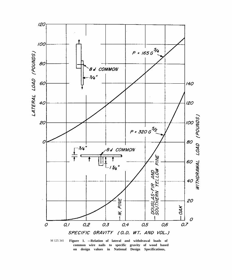
M 125 341 Figure 1. --Relation of lateral and withdrawal loads of common wire nails to specific gravity of wood based on design values in National Design Specifications,
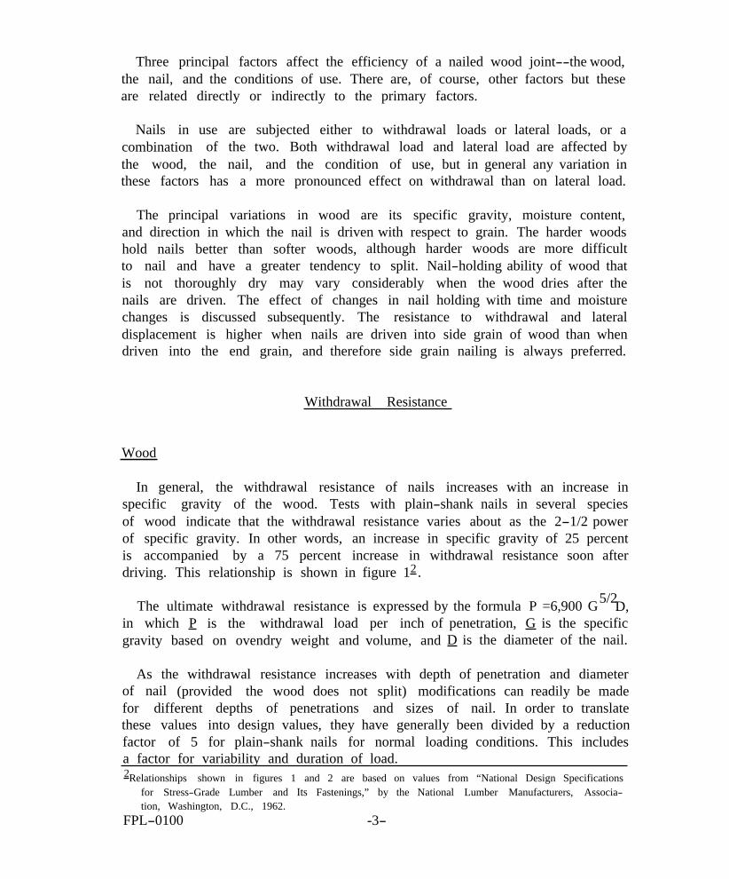
Three principal factors affect the efficiency of a nailed wood joint--the wood, the nail, and the conditions of use. There are, of course, other factors but these are related directly or indirectly to the primary factors.
Nails in use are subjected either to withdrawal loads or lateral loads, or a combination of the two. Both withdrawal load and lateral load are affected by the wood, the nail, and the condition of use, but in general any variation in these factors has a more pronounced effect on withdrawal than on lateral load.
The principal variations in wood are its specific gravity, moisture content, and direction in which the nail is driven with respect to grain. The harder woods hold nails better than softer woods, although harder woods are more difficult to nail and have a greater tendency to split. Nail-holding ability of wood that is not thoroughly dry may vary considerably when the wood dries after the nails are driven. The effect of changes in nail holding with time and moisture changes is discussed subsequently. The resistance to withdrawal and lateral displacement is higher when nails are driven into side grain of wood than when driven into the end grain, and therefore side grain nailing is always preferred.
Withdrawal Resistance
Wood
In general, the withdrawal resistance of nails increases with an increase in specific gravity of the wood. Tests with plain-shank nails in several species of wood indicate that the withdrawal resistance varies about as the 2-1/2 power of specific gravity. In other words, an increase in specific gravity of 25 percent is accompanied by a 75 percent increase in withdrawal resistance soon after driving. This relationship is shown in figure 12.
The ultimate withdrawal resistance is expressed by the formula P =6,900 G 5/2D, in which P is the withdrawal load per inch of penetration, G is the specific gravity based on ovendry weight and volume, and D is the diameter of the nail.
As the withdrawal resistance increases with depth of penetration and diameter of nail (provided the wood does not split) modifications can readily be made for different depths of penetrations and sizes of nail. In order to translate these values into design values, they have generally been divided by a reduction factor of 5 for plain-shank nails for normal loading conditions. This includes a factor for variability and duration of load. 2Relationships shown in figures 1 and 2 are based on values from “National Design Specifications
for Stress-Grade Lumber and Its Fastenings,” by the National Lumber Manufacturers, Association, Washington, D.C., 1962.
FPL-0100 -3
The largest factor affecting the withdrawal resistance of plain-shank nails is the reduction in load that accompanies changes in moisture content of the wood after the nail is driven. In practically all species, nails driven into green wood and pulled before any seasoning takes place offer about the same withdrawal resistance as nails driven into seasoned wood and pulled soon after driving. If, however, common smooth-shank nails are driven into green wood that is allowed to season or into seasoned wood that is subjected to cycles of wetting and drying before the nails are pulled, they lose a major part of their withdrawal resistance. In seasoned wood that is not subjected to appreciable moisture content changes, the withdrawal resistance of plain-shank nails may also diminish with lapse of time.
On the other hand, tests indicate that if the wood fibers are affected or some rust develops, withdrawal resistance is very erratic and may even be increased over the immediate withdrawal resistance.
Under all these conditions of use, the withdrawal resistance of nails differs among species as well as within individual species, making it difficult to evaluate their behavior. The withdrawal load for common plain-shank nails driven into wood that is subjected to changes in moisture content may be as much as 75 percent below the values given by the general formula. For annular or helically threaded nails the withdrawal values are not greatly affected by time and moisture changes.
Nails
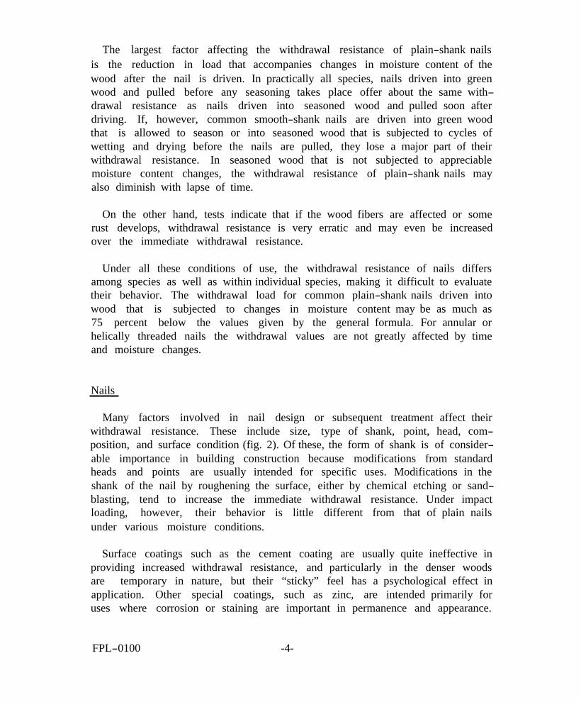
Many factors involved in nail design or subsequent treatment affect their withdrawal resistance. These include size, type of shank, point, head, composition, and surface condition (fig. 2). Of these, the form of shank is of considerable importance in building construction because modifications from standard heads and points are usually intended for specific uses. Modifications in the shank of the nail by roughening the surface, either by chemical etching or sandblasting, tend to increase the immediate withdrawal resistance. Under impact loading, however, their behavior is little different from that of plain nails under various moisture conditions.
Surface coatings such as the cement coating are usually quite ineffective in providing increased withdrawal resistance, and particularly in the denser woods are temporary in nature, but their “sticky” feel has a psychological effect in application. Other special coatings, such as zinc, are intended primarily for uses where corrosion or staining are important in permanence and appearance.
FPL-0100 -4
M 125 342 Figure 2. --Relation of lateral and withdrawal loads to diameter and length of common wire nails based on design values in National Design Specifications.
Nails of copper alloys, aluminum alloys, stainless steel, and other alloys are also used mainly where corrosion or staining are factors in appearance or permanence. Specially hardened nails are also frequently used where driving conditions are difficult or where high lateral loads require nails harder than those of ordinary steel.
One of the major improvements in nailed fastenings has been the development of the annular or helically threaded nails, The primary advantage of these nails is that their withdrawal resistance is not appreciably affected by time and moisture changes in the wood. They provide a much more reliable fastening as they are not subject to the variability and reduction in load common to the plain shank nail in many uses.
Conditions of Use
The requirements for conditions of use depend on a large number of factors. These include the relative importance of the joint in the structural strength and stability of the structure, the type of material being attached, the type and moisture content of the material into which the nail is driven, and the subsequent service conditions of the joint.
In many instances, nails are used primarily to position a member or to hold members together until a covering material is provided that will tie all the units together. Nails used to hold the framework in a wall together, for example, may or may not be very important. If they are needed to anchor the wall, they are of considerable importance. On the other hand, the racking resistance provided by the joints in the framework is relatively small, in comparison to that provided by suitable braces or properly installed coverings.
Lateral Resistance
The lateral resistance provided by nailed joints is frequently a critical factor in the strength and stability of a structure or its component parts. As mentioned previously, factors such as the wood, the nail, and conditions of use are generally not so pronounced under lateral loads as under withdrawal loads. However, they still are of considerable importance.
Wood
The spread in the lateral resistance between different species or members of low or high specific gravity is not so large as in withdrawal. While species
FPL-0100 -6
are frequently grouped in tables to simplify presentation of loads, in general the loads for nails in side grain nailing vary about as the 1-1/4 power of specific gravity (fig. 1). On this basis an increase in specific gravity of 25 percent is accompanied by an increase of somewhat more than 30 percent in lateral loads.
This relationship (fig. 1) can be expressed by the formula P =KG5/4 in which P is the lateral load, K is a constant depending on size and type of nail and reduction factors translating test loads into design loads, and G is the specific gravity based on ovendry weight and volume.
While the large variation in properties of wood along and across the grain has considerable effect on the load-carrying capacity of most fastenings, the lateral load values for nails are approximately the same regardless of direction of bearing in the side grain of wood. When nails are driven into end grain, however, the values are somewhat less than when driven into side grain. The ratio varies with the amount of distortion but, for design purposes, the lateral resistance of nails in end grain is considered to be about two-thirds of that in side grain.
Nail
The factors that affect lateral resistance of nails, apart from the species and dimensions of wood members in the joint, are related primarily to the nail diameter, providing that the depth of penetration in the member receiving the point is adequate (fig. 2). Within the working range of design value, the lateral resistance is dependent on the resistance of the nail to bending and varies approximately as the 1-1/2 power of the diameter. A somewhat higher maximum lateral load is obtained with nails that have a higher withdrawal resistance because, at the maximum load, some withdrawal occurs as well as bending of the nail and crushing of the wood. The maximum load, however, is usually obtained at a slip in the joint of 1/4 to more than 1/2 inch, which is far beyond the working range for most uses. The quality of metal in the nail will also have an effect on the lateral load to the extent that it affects the resistance to bending.
Service Conditions
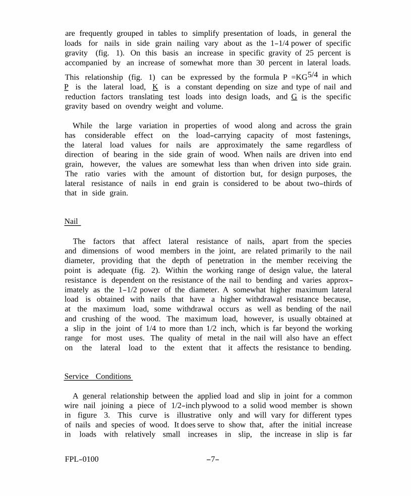
A general relationship between the applied load and slip in joint for a common wire nail joining a piece of 1/2-inch plywood to a solid wood member is shown in figure 3. This curve is illustrative only and will vary for different types of nails and species of wood. It does serve to show that, after the initial increase in loads with relatively small increases in slip, the increase in slip is far
FPL-0100 -7
M 1
25 3
35
Fig
ure
3. -
-Ty
pic
al r
elat
ion
bet
wee
n l
ate
ral
loa
d a
nd
va
riou
s in
crem
ents
of
sl
ip
in
the
join
t.
greater than the increase in load. For example, the loads at 0.25-inch slip are only about double those at 0.025-inch slip. In other words, beyond a certain distortion, each 10 percent increase in load is accompanied by a 50 percent increase in slip of the joint.
The lateral nail load that should be used in design, therefore, is a function not only of the ultimate load capacity of the joint but also of the amount of distortion. For some joints where the amount of distortion is relatively unimportant, loads can be used that include only such reduction factors as variability, long-time loading, and safety.
For joints where the amount of distortion in the joint must be limited, as in a roof truss, the rigidity of the joint as well as the load must be taken into consideration. In fact, the limiting factor in such joints is usually the slip rather than the load, since the ultimate load generally exceeds the load that would normally be required to satisfy the reduction factors.
The design values as now established are based primarily on a limiting amount of slip. While adequate data are not available to establish a relationship between the load that can withstand repeated applications and the maximum, some preliminary investigations indicate that a load at 0.015-inch slip for the size of nails used in construction is not accompanied by a sizable amount of “creep” in service. (In many joints the maximum load is from 3 to 4 times the load obtained at a slip of 0.015 inch.) Actually the selection of a specific limit of slip as a criteria for establishing design is not entirely satisfactory and not generally applicable because the slip in the joint varies with such factors as size and type of nail, quality of metal, and species and size of wood members.
However, the importance of a limitation on joint slip can be better recognized when translated into the resulting effect of joint slip on such a construction as a truss. For a truss construction with a rafter slope of 2-1/2 in 12; a slip of 1/16 inch at each heel joint and at the center splice plate in the lower chord will result in a sag of nearly 1/2 inch at the peak of the truss. If a double joint is used at the center of the lower chord, the sag will be even more. There may, of course, be some offsetting factors such as braces and other supporting members, but the potential for sag with any appreciable slip in the joints is there.
Depth of Penetration
The lateral nail load is also related to the depth of penetration of the nail in the foundation member or member receiving the point. The depth of penetration generally recommended for plain-shank nails to develop full load varies
FPL-0100 -9
Figu
re
4.
--V
ario
us
com
bina
tions
of
th
ickn
ess
of
mem
bers
in
tw
o-an
d th
ree -
mem
ber
join
ts
and
leng
th
and
diam
eter
of
na
il.
Nai
l pe
netr
atio
n in
m
embe
r re
ceiv
ing
poin
t in
te
rms
of
diam
eter
is
: A
=
15.4
0;
B
= 6.
2D;
C
= 7.
2D;
and
D =
4.3
D.
M
123
223
from about 10 times the nail diameter for hardwoods to 14 times for the softer woods. For structural species it is usually taken at 11 times the diameter. For lesser depths of penetration, the maximum load tends to be reduced but not the load at smaller distortions. This results because the maximum lateral load is associated with nail withdrawal, whereas the load at smaller distortions is associated with the bending resistance of the nail. Since the maximum lateral load is associated with nail withdrawal, the depth of penetration required varies with the relative withdrawal resistance of the nails. For comparable maximum lateral loads, therefore, nails with a higher withdrawal resistance would require a somewhat smaller depth of penetration.
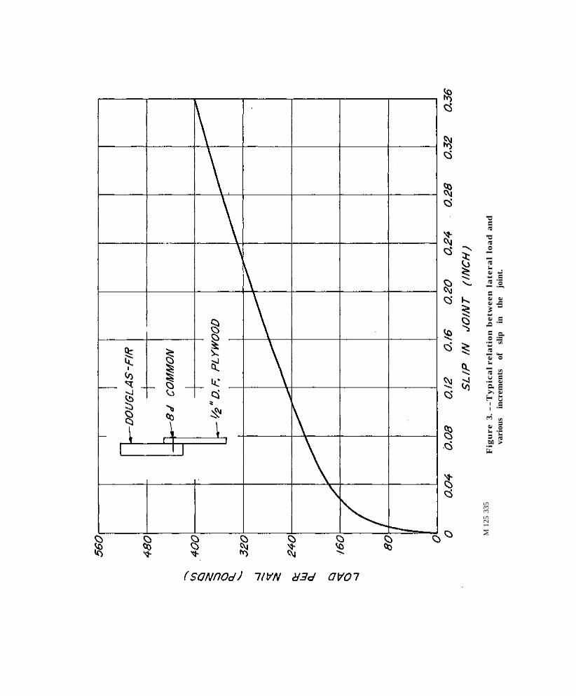
The general relationship between the depth of penetration into the member receiving the nail point and lateral nail load developed for two-member joints is also applicable to the third member of a three-member joint (third member has nail point). Whereas in a two-member joint a thinner member is usually attached to a thicker member (as a 1-inch member to a 2-inch member), in a three-member joint the situation is reversed. Thus, a three-member joint is essentially equivalent to attaching the thicker member to the thinner or third member (as a 2-inch member to a 1-inch member) (fig. 4). The relationship in load between the second and third member, as compared to the load between the first and second member, may range from one-third to one, depending on the type of nail, the thickness of the third member with respect to nail diameter, and the factor desired between the maximum load and working load.
Toenailing
While the nails in many joints serve a dual function of resisting withdrawal and lateral loads, the dual function is particularly evident in toenailed joints where the nails must resist separation between the two joined members in the plane of the members and at right angles to it.
Toenailing, when used to join wood framing members at right angles to each other, consists of slant driving a nail or group of nails through the end or edge of an attached member and into a main member. Tests show that the maximum strength of toenailed joints under lateral and uplift loads is obtained by (1) using the largest nail that will not cause excessive splitting; (2) allowing an end distance (distance from end of the attached member to the point of initial nail entry) of approximately one-third the length of the nail; (3) driving the nail at a slope of 30° with the attached member; and (4) burying the full shank of the nail but avoiding excessive mutilation of the wood from hammer blows.
FPL-0100 -11
Toenailing requires greater skill in assembly but provides joints of greater strength and stability than does ordinary end nailing. In tests of stud-to-sill assemblies with the number and size of nails frequently used in toenailed and end-nailed joints, a joint toenailed with four eightpenny common nails was superior to a joint end nailed with two sixteenpenny common nails. The withdrawal load per nail in toenailed joints for all conditions of seasoning is equivalent to two-thirds of that determined for the direct withdrawal resistance of nails.
Spacing of Nails
The spacing of nails in multi-nail joints depends on the size and type of nail and tendency of the wood to split. The splitting tendency varies with so many factors that it is difficult to provide rules on spacing that are generally applicable. The splitting tendency first of all varies with species of wood. Usually the softer the wood the less likelihood of splitting, but splitting can also be affected by such factors as the relative hardness and structure of the wood as well as the ratio between the properties across and along the grain.
The moisture content of wood and variations in its moisture content also affect the tendency to split. While wood that is green tends to split less than wood that is dry, partially seasoned wood may actually split much more severely than dry wood. During drying, the outer surfaces of the wood dry first and tend to shrink, but the shrinkage is resisted by the inner core, which is still green and retains its original dimensions. Consequently, at certain stages in the drying process the outer surfaces of the member are in tension and split quite readily when pierced by a nail. The splitting may vary from day to day in the same wood member, depending on its moisture content and on the temperature and humidity in the surrounding atmosphere.
Several investigations have been made to evaluate the splitting characteristics of wood and to correlate the inherent properties of wood with its splitting tendencies, but none have provided satisfactory results. Results obtained in laboratory experiments do not always duplicate the results obtained in practice,
Some general guidelines have, however, been developed over a period of time based on laboratory experiments and practice. One of these involves the relationship between the nail diameter and thickness of wood member. This rule provides that the nail diameter should be one-sixth or one-seventh of the thickness of the attached wood member. For example, an eightpenny common nail has a diameter of 0.131 inch and, therefore, could be used with a board
FPL-0100 -12
having a thickness of about 0.8 inch. This conforms closely to the standard practice of using a nail diameter equivalent to or smaller than the eightpenny common nail in a nominal 1-inch board.
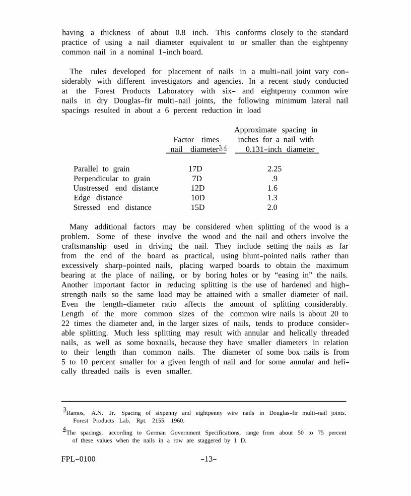
The rules developed for placement of nails in a multi-nail joint vary considerably with different investigators and agencies. In a recent study conducted at the nails in spacings
Forest Products dry Douglas-fir
resulted in about
Laboratory with six- and eightpenny common multi-nail joints, the following minimum lateral a 6 percent reduction in load
wire nail
Factor times nail diameter3,4
Approximate spacing in inches for a nail with
0.131-inch diameter
Parallel to grain 17D 2.25 Perpendicular to grain 7D .9 Unstressed end distance 12D 1.6 Edge distance 10D 1.3 Stressed end distance 15D 2.0
Many additional factors may be considered when splitting of the wood is a problem. Some of these involve the wood and the nail and others involve the craftsmanship used in driving the nail. They include setting the nails as far from the end of the board as practical, using blunt-pointed nails rather than excessively sharp-pointed nails, placing warped boards to obtain the maximum bearing at the place of nailing, or by boring holes or by “easing in” the nails. Another important factor in reducing splitting is the use of hardened and high-strength nails so the same load may be attained with a smaller diameter of nail. Even the length-diameter ratio affects the amount of splitting considerably. Length of the more common sizes of the common wire nails is about 20 to 22 times the diameter and, in the larger sizes of nails, tends to produce considerable splitting. Much less splitting may result with annular and helically threaded nails, as well as some boxnails, because they have smaller diameters in relation to their length than common nails. The diameter of some box nails is from 5 to 10 percent smaller for a given length of nail and for some annular and helically threaded nails is even smaller.
3Ramos, A.N. Jr. Spacing of sixpenny and eightpenny wire nails in Douglas-fir multi-nail joints. Forest Products Lab, Rpt. 2155. 1960.
4The spacings, according to German Government Specifications, range from about 50 to 75 percent
of these values when the nails in a row are staggered by 1 D.
FPL-0100 -13
JOINTS MADE WITH STAPLES AND SCREWS
While this note pertains primarily to nailed joints, other fastenings for special uses or for the application of specific materials have been developed for use in construction, A discussion of all these fastenings is beyond the scope of this publication, but a few comments are included on staples and screws since their use frequently overlaps that of nails in specific joints.
Staples
Different types of staples have been developed with various modifications in points and shanks to fulfill either general or specific requirements. Many factors that affect the withdrawal and lateral loads of nails similarly affect the loads on staples. The withdrawal resistances, for example, vary almost directly with the circumference and depth of penetration when the type of point and shank are similar.
The load in lateral resistance varies about as the 3/2 power of the diameter when other factors, such as quality of metal, type of shank, and depth of penetration are similar. The diameter of each leg of a two-legged staple must therefore be about 2/3 the diameter of a nail to provide a comparable load,
In addition to the immediate holding capacity of staples and nails as determined by test, however, such factors as corrosion, sustained performance under service conditions, and durability evaluating the relative usefulness of
in various uses should be considered in a connection.
Screws
Screws have many advantages as fasteners for specific uses in wood construction. They have a relatively high resistance to withdrawal and greater permanence than many other types of fastenings. Screws are, therefore, a preferred fastening where the joint is subjected to rigorous treatment or where it may be necessary to take the members apart.
FPL-0100 -14-
Wood screws are usually made of steel or brass, and may also be made in a nickel or blued finish. They are classified according to material, type, finish, shape of head, and diameter or gage of wire from which they are made. The particular type required is dependent on its use.
The resistance of wood screws to withdrawal is closely related to the specific gravity of the wood, the diameter and length of the screw, the size of lead hole, and the type of screw thread and hole surface.
This resistance to withdrawal from the side grain of seasoned wood varies about as the square of the specific gravity of the wood. The relative design load in withdrawal resistance per inch of penetration for a No. 10 screw, for example, varies from about 75 pounds in white pine to over 270 pounds in white oak. Tests indicate that, with certain limits, the withdrawal load of screws varies directly with the depth of penetration and the diameter of the screw. The limiting factor in the length is the failure of screw in tension.
The lateral resistance of screws is important in many uses. Under a lateral or side load, the strength of the joints increases about as the square of the screw diameter; when the diameter of the screw is doubled, the load is increased four times, The lateral resistance does not vary as much between species as the withdrawal resistance, but the effect of specific gravity on load is still large. The relative lateral design load for a No. 10 screw, for example, is 90 pounds in white pine and about 175 pounds in white oak. The maximum load, of course, is considerably higher. The lateral loads listed in such publications as National Design Specifications usually apply to screws driven into the side grain of wood in which the depth of penetration into the foundation member is at least seven times the screw diameter.
The load the screws will carry is affected to a considerable extent by the size of lead hole. Prebored lead holes are commonly required in order to reduce their tendency to split the wood and to facilitate insertion unless the wood is soft or special threaded screws are used. The best results are usually obtained with a lead hole for the threaded portion of a wood screw, or full length of a sheet metal screw, that has a diameter of 70 percent of the root diameter of the threads for softwoods and 90 percent for hardwoods.
FPL-0100 -15-
FASTENINGS--AND COST
In general, the structural framework of a house is only a small part of the total cost. It is not prudent to overdesign or assemble the structural part of a house inefficiently, but neither is it prudent to save pennies in the structural part of the house and forget about the dollars expended for fancy gadgetry or the satisfaction of whims in the completion of a house. For some reason, the little extra cost for proper nails and fastenings is usually magnified out of all proportion to their benefits. Proper fastenings pay off many times over.
Related Publications Available From FPL
Nail resistance of American woods. U.S. Forest Serv. Res. Note FPL-093. 1966.
Nailing dense hardwoods. U.S. Forest Serv. Res. Note FPL-037, 1964.
General observations on the nailing of wood. FPL Tech. Note 243. Reissued 1962.
Nailing better wood boxes and orates, by L. O. Anderson. U.S. Dept. Agr., Agr. Handb. 160, 1959.
Theoretical design of a nailed or bolted Joint under lateral load, by Edward W. Kuenzi. FPL Rpt. 1961. Information reviewed and reaffirmed 1960.
Timber fastenings. Separate from Wood Handbook. U.S. Dept. Agr., Agr. Handb. 72, 1955.
Nail-holding properties of southern hardwoods, by John A. Scholten. South, Lbrman. Dec. 16, 1950.
Strength of nailed joints in frame walls, by John A. Scholten and E. G`, Molander. Agr. Eng. 31 (11). Nov. 1950.
FPL-0100 -16- 1.3-18
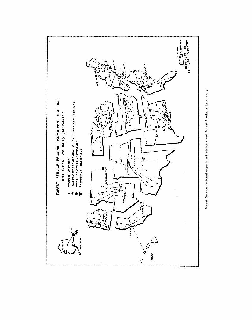
Fore
st S
ervi
ce r
egio
nal
expe
rim
ent
stat
ions
and
For
est
Pro
duct
s La
bora
tory

FOREST PRODUCTS LABORATORY