Embed Size (px)
Citation preview
Tailor Made Concrete Structures – Walraven & Stoelhorst (eds)© 2008 Taylor & Francis Group, London, ISBN 978-0-415-47535-8
Strengthening and design of shear beams
N. RandlCarinthia University of Applied Sciences, Spittal, Austria
J. KunzHilti Corp., Schaan, Liechtenstein
ABSTRACT: Concrete beams may fail in shear depending on kind of loading and amount of shear reinforce-ment. A research project has been started to investigate a new method of strengthening beams with insufficientshear resistance by applying post-installed reinforcement and in parallel derive an adequate model for sheardesign. Number and location of the inclined rebars as well as type of injection mortar has been varied. The rebarswere installed in mortar-injected boreholes and anchored with metal plates at the accessible bar end. The testresults confirmed that post-installed rebars can significantly increase the beam shear resistance provided they aresituated properly and adequate injection mortars used. Above that the evaluation of the different contributions toshear resistance like truss action, dowel action and shear strength of compression chord provides new findingson the general shear failure mechanism in RC structures.
1 SHEAR FAILURE OF CONCRETE BEAMS
Vertically loaded beams may fail due to shear action inthree different ways: Flexural cracks may extend intothe inner sections or the web of the member, respec-tively, where they follow more and more the diagonaldirection of the principal compression stresses andfinally propagate into the concrete compression zone(bending-shear failure mode). The two other shearfailure modes may especially occur at RC memberswith flanged cross-sections consisting of strong lon-gitudinal tension and compression chords and thinweb parts: In this case web-shear cracks may developbefore flexural cracking. Provided the amount of shearreinforcement is sufficient, the shear strength can belimited by diagonal crushing of the concrete strutsin the web. Otherwise widening of the inclined shearcracks may lead to yielding of the shear reinforcement.
In extensive experimental studies during the lastdecades it turned out that in fact the shear load bear-ing capacity is significantly higher than reflected bythe idealized truss. Tests show that the inclination ofshear cracks is less than 45◦ and simultaneously theactual shear reinforcement stresses are lower than cal-culated. This is due to several effects: At ultimateload stage the compression stresses follow an arch-like structure within the member, thereby transferringa part of the vertical loads directly to the end supports.On the other hand the truss nodes are not frictionless
Figure 1. Fundamental “Truss analogy”.
hinges and therefore able to transfer certain moments.Moreover, reinforcement crossing the cracks will resistbending with its flexural capacity, and friction forcesmay develop across cracks due to aggregate inter-lock. Reineck (2001) points out in his fundamentalapproach, the so-called “Truss Analogy with CrackFriction“ the effect of friction across the shear crackswhile Koenig (2000) or Hegger (2006) in recent yearsquestion the significance of this mechanism. Accord-ing to Eurocode 2 (2001) the different mechanismscontributing to the overall shear resistance in additionto the truss action are taken into account by allow-ing the designer to vary the inclination of the diagonalcompression struts, thereby minimizing the requiredshear reinforcement. ACI 318 (2002) design provi-sions on the other hand are based on a truss model withcompression struts inclined at 45◦ and recommend todesign for shear forces by adding a shear resistanceprovided by the concrete to the shear reinforcementresistance.
657

Rebars 16
s3 s2 s1 a = 900 mm
B
B
A
A
123
4 ∅22
4 ∅14
4 ∅22
4 ∅14
A – A: B – B:
d
300
400
Figure 2. Test specimen.
2 STRENGTHENING RC BEAMS WITHPOST-INSTALLED SHEARREINFORCEMENT
There exist different methods of post-strengtheningRC beams in cases where the ultimate resistance undervertical loads would be governed by shear failure.Beam-like members can be externally strengthenedby flat steel strips or carbon fibre reinforced polymersheets (CFRP) laterally fixed to the concrete by anepoxy. Another option is to place new concrete lay-ers (cast-in place or shotcrete) and utilize it also forenhancing the shear strength, provided that the transferof internal stresses across the bond interface is assuredand shear reinforcement is anchored adequately in theold and new concrete. The disadvantages of the lat-ter method are that either the existing cross-section ischanged (especially when applying concrete overlaysor shotcrete layers) or substantial construction worksare required on the top side as well. For the externallybonded reinforcement, the long term behaviour or thefire resistance may become a limiting factor.
The method investigated in the present projectavoids changes of the outer dimensions of the memberand fits well to the RC-concept and way of designingstructures: Post-installed inclined reinforcement barsφ16 are installed in mortar-injected boreholes from thebottom side of the shear beams (Fig. 2). Neighbour-ing parts of the structure are thereby not damaged andwork on the decking zones avoided so that the usabil-ity during construction works is not heavily affected.The experiments were performed in the accredited lab-oratory of the Hilti Corporation and evaluated at theUniversity of Applied Sciences in Carinthia, Austria.
3 EXPERIMENTAL PROGRAM
The overall testing program and the varying parame-ters are listed in table 1. The test specimens consist ofa RC-beam as outlined in Fig. 2.
The shear slenderness a/d has been chosen rathersmall (∼3,4) in order to guarantee that shear failure
Table 1. Experimental program.
Bars wstrain s1 s2 s3 Resin
Beam Bars gauge [cm] [cm] [cm] type ****
1 0 – – – – –2 6 (2 × 3) 3 35,6 25,6 25,6 cem3 6 (2 × 3) 3 35,6 25,6 25,6 cem4 6 (2 × 3) 3 35,6 25,6 25,6 ep b5 6 (2 × 3) 3 35,6 25,6 25,6 ep b6 4 (2 × 2) 4 35,6 38,4 – cem7 4 (2 × 2) 4 35,6 38,4 – ep b8 6 (2 × 3) 0** 35,6 27,6 23,6 cem9 4 (2 × 2) 1*** 35,6 25,6 – cem10 0 – – – – –
*post installed shear reinforcement, D = 16 mm, 45◦inclination.**anchor plates without slip on top and bottom side.***inner reinforcement bar.****cem = cementitious, ep b = epoxy based
becomes decisive, however large enough to minimizethe direct transfer of compression forces from the loadintroduction zone to the support. The vertical dis-placements have been recorded with LVDTs (linearvariable differential transformers) applied on both topand bottom side of the beams, additional LVDTs wereapplied in diagonal direction during the tests. More-over, strain gauges were attached along the inclinedshear reinforcement bars as listed in table 1.
The number and location of the 45◦ degrees inclinedpost-installed rebars has been varied as well as the typeof injection mortar for bonding-in the reinforcement.The rebars in this case have been anchored with metalplates at the accessible bar end on the bottom side, thetop end of the rebars was bonded-in at the upper sideof the beams. Two mortars approved for anchorageof post-installed rebars were used, one cementitiousanorganic and an organic epoxy-type mortar. Undernormal application conditions anchorage lengths ofabout 6 diameters in the first case and only about 4diameters with the epoxy adhesive are sufficient toreach yielding of the steel. This is the case, if meanultimate bond strength is considered and if the edgedistance is large enough to prevent concrete splitting,thus comparable to cast-in reinforcement bars.
4 EVALUATION OF THE TESTS
All tested beams failed due to a premature shear rup-ture. The beam bending resistance was not decisiveand the yield strength of the upper tensile reinforce-ment never reached. The recording of displacementson the top and bottom side of the beams, crack widthsin correspondence with each load step as well as steelstrains at several points along the post-installed rebars
658

Figure 3. Experimental setup (test 8).
Figure 4. Upwards deflection (test 8).
exhibits a coherent pattern of the internal mechanismsat the different load steps.
The two reference tests without shear reinforce-ment showed the typical behaviour as expected fromcomparable tests described e.g. by Görtz (2004).Test 1 was performed at the beginning of the testseries and reached an ultimate load of 237 kN, test10 being performed at the end of the test seriesyielded 287 kN. The mean ultimate shear resistance istherefore taken as 262/2 = 131 kN. According to EC2(2001) the value for the shear resistance is given byVRcm = 0,18*(1 + (200/d)ˆ0,5)*(100*ρ*fcm)1/3.Inserting the relevant parameters, the calculated valueis 140 kN, thus fitting well to the test results (never-theless EC2 (2001) would require a minimum shearreinforcement for beam-like members). The indenta-tion of the cross section in the central part of the beamwith a maximum in the load introduction zone has nomajor influence.
In the following paragraphs the test results of beams2–9 with shear reinforcement are discussed. Figure 3shows a photograph of a beam at failure and figure 4the corresponding typical load displacement curves atdifferent load levels.
Some general observations concerning develop-ment and propagation of cracks can be summarizedas follows:
– In each test the first cracks developed in the flexuraltension zone perpendicular to the edge and quicklyprogressed to the inner web zone of the beam. Thecrack inclination changed from more or less 45˚ inthe web zone to a very smooth angle when the crackfinally approached the compression flange on thebottom side.
Figure 5. Failure crack (test 2).
Figure 6. Differential displacements (test 2).
– With increasing load, in the zone of the upper longi-tudinal tension reinforcement the main crack moreand more took course parallel to the reinforcementbar, thereby “bypassing” the bar’s full dowel actionresistance.
– Even with shear crack widths larger than 1mm stilla significant load increase was observed.
– At failure typically one main crack with an averageinclination of ∼45˚ opened progressively, the crackwidth finally reaching about 2-3 mm (Fig. 5).
– The main crack always propagated rather quicklyfrom the flexural tension zone to the compres-sion chord. However, approaching the compressionflange crack propagation decelerated until the com-pression chord failed. The failure of the compres-sion chord appeared rather abruptly, i.e. a quickfracture without preceding visible hairline cracks.
4.1 Analysis
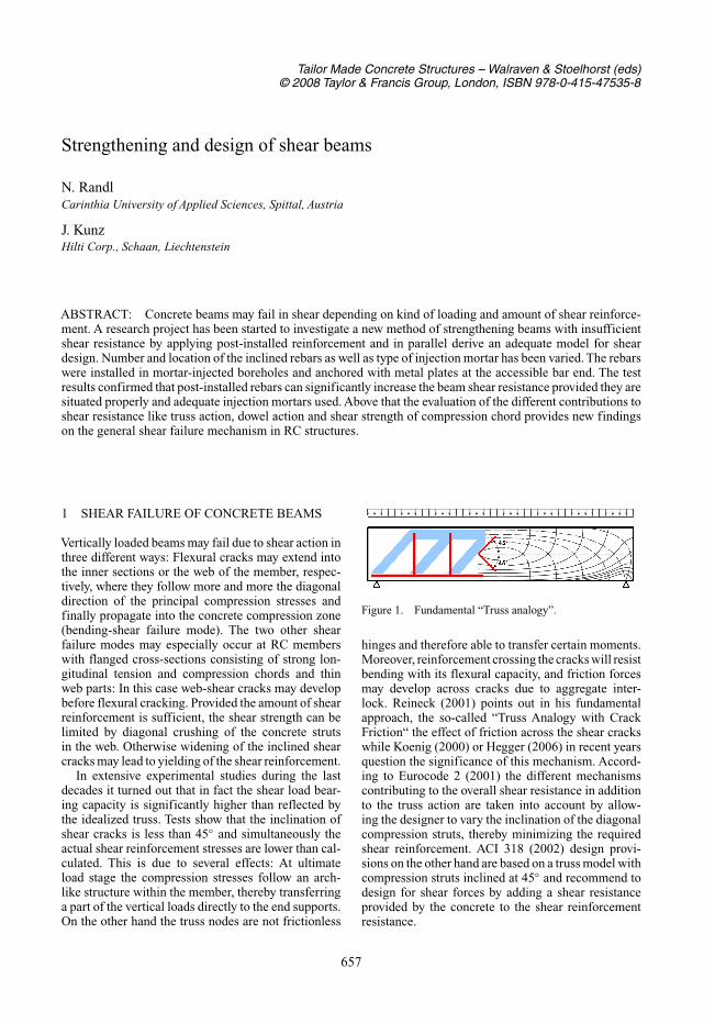
In order to identify and quantify the different internalmechanisms at the failure stage, the single contribu-tions to the overall shear resistance are backtrackedon the basis of the displacement and strain recordingsand the visible crack pattern. To establish a verticalequilibrium of forces along the inclined cracks, themid part of the beam was separated and the relevantinternal forces were applied (Fig. 7).
659
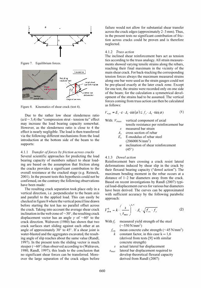
Figure 7. Equilibrium forces.
Figure 8. Kinematics of shear crack (test 4).
Due to the rather low shear slenderness ratio(a/d ∼ 3,4) the “compression strut - tension tie” effectmay increase the load bearing capacity somewhat.However, as the slenderness ratio is close to 4 theeffect is nearly negligible. The load is then transferredvia the following different mechanisms from the loadintroduction at the bottom side of the beam to thesupports:
4.1.1 Transfer of forces by friction across cracksSeveral scientific approaches for predicting the loadbearing capacity of members subject to shear load-ing are based on the assumption that friction alongthe cracks provides a significant contribution to theoverall resistance at the cracked stage (e.g. Reineck,2001). In the present tests this hypothesis could not beconfirmed, on the contrary the following observationshave been made:
The resulting crack separation took place only in avertical direction, i.e. perpendicular to the beam axisand parallel to the applied load. This can easily bechecked in figure 8 where the vertical pencil line drawnbefore starting the test has no parallel offset acrossthe crack. Taking into account the average shear crackinclination in the web zone of ∼30◦, the resulting crackdisplacement vector has an angle γ of ∼60◦ to thecrack direction. Walraven (1980) has shown that twocrack surfaces start sliding against each other at anangle of approximately 30◦ to 45◦. If a shear joint iswater-blasted and the aggregates excavated, the result-ing angle of slip reaches about the same value (Randl,1997). In the present tests the sliding vector is muchsteeper (∼60◦) than observed according to (Walraven,1980, Randl, 1997); this leads to the conclusion thatno significant shear forces can be transferred. More-over the large separation of the crack edges before
failure would not allow for substantial shear transferacross the crack edges (approximately 2–3 mm). Thus,in the present tests no significant contribution of fric-tion across cracks could be proven and is thereforeneglected.
4.1.2 Truss actionThe inclined shear reinforcement bars act as tensionties according to the truss analogy. All strain measure-ments showed varying tensile strains along the rebars,reaching their final maximum in the vicinity of themain shear crack. For back-tracking the correspondingtension forces always the maximum measured strainsalong one bar were used as the strain gauges could notbe pre-placed exactly at the later crack zone. Exceptfor one test, the strains were recorded only on one sideof the beam; for the calculation a symmetrical devel-opment of the strains had to be assumed. The verticalforces coming from truss action can then be calculatedas follows:
With: Vtruss vertical component of axialtensile resistance per reinforcement bar
ε measured bar strainAs cross section of rebarEs E-modulus of rebar steel
(206000 N/mm2)α inclination of shear reinforcement
(45◦)
4.1.3 Dowel actionReinforcement bars crossing a crack resist lateraldeformations induced by shear slip in the crack bytheir flexural bearing capacity (“dowel action”). Themaximum bending moment in the rebar occurs at adistance of 1–2 bar diameters away from the crack.Based on recent investigations by Randl (2007) typi-cal load-displacement curves for various bar diametershave been derived. The curves can be approximatedwith sufficient accuracy by the following parabolicapproach:
With fy measured yield strength of the steel(∼550 N/mm2)
fcm mean concrete cube strength (∼45 N/mm2)k constant factor, in this case k = 1,6
(derived from tests [9] with similarconcrete strength)
s actual lateral bar displacementsmax lateral bar displacement required to
develop theoretical flexural capacityderived from Randl (2007)
660

Figure 9. Typical curves for dowel action (Randl, 2007).
The crack opening in the vertical direction canbe approximated by the difference of the deforma-tions recorded at the top and bottom side of thebeam (Fig. 6). This approach is justified as in gen-eral one progressively opening main shear crack canbe observed; moreover it was checked with the record-ings of the diagonal LVDTs later applied along themain crack. As no horizontal deformation has beenrecorded (Fig. 8), the lateral bar displacement s canthen be derived by multiplying the measured verticaldisplacement with cosα (here: α = 45◦, Fig. 8). If theangle β between rebar and crack deviates from 90◦,the smoother crossing of the crack leads to a reductionof the theoretical dowel action derived from tests withshear slip perpendicular to the dowel. This effect canbe approximated by multiplying formula (2) with sinβ,β being measured at the cracked specimen.
In addition to the shear slip in the crack therebars are simultaneously subjected to axial tensionforces. Based on the strain recordings representingthe axial tension forces in the rebars, the reductionof the ultimate bending moment can be roughly takeninto account by applying the reduction factor as perequation (3) (Randl, 1997, Randl & Wicke, 2000,Tsoukantas & Tassios, 1989):
4.1.4 Dowel action of longitudinal tensilereinforcement
The 4 upper longitudinal tensile reinforcement barsØ22 resist the propagation of the shear crack by dowelaction. The theoretical value of dowel action would benearly 100 kN per bar according to formula (2), forall 4 bars on each side this would result in a total of∼800 kN. However, as also observed in the present
Figure 10. Load stage before failure of compression chord(Test 7).
tests this usually leads to a change in the crack direc-tion so that finally the crack crosses the rebar nearlyparallel to the bar axis at a very smooth angle wherethe reinforcement cannot develop its full flexural resis-tance. In the present evaluation, the dowel action ofthe longitudinal tension reinforcement is thereforeneglected.
4.1.5 Compression flangeAs explained above, ultimate beam failure coincidedfinally with an abrupt rupture of the compressionchord. The shear resistance V0c of the remaining com-pression zone before cracking can be approachedaccording to Zink (1999) and Görtz (2004) on the basisof a linear stress distribution (”basic value” accordingto Zink):
Deviating from Zink (1999), the height x of the com-pression zone is assumed to be equal to the heightof the compression flange of the cross section in thevicinity of the load introduction zone.
The rationale for this approach is based on theobserved crack propagation before failure as notice-able in Fig. 10 depicting a typical load stage beforefailure:The shear cracks first approach more and morethe compression flange, thereby propagating along thetop edge of the flange towards the beam centre wherethe load is introduced, before then sudden rupture ofthe flange induces the beam failure.
5 DISCUSSION OF THE TEST RESULTS
The theoretical contributions of the different mech-anisms as per formulae 1–4, calculated on the basisof the measured strains and deformations, have beensuperposed and the maximum strength checked foreach specimen. The results are listed in the followingtable 2.
Comparing the experimental (Fu,exp) and the theo-retical failure loads (Fu,cal), derived from superposingthe calculated single contributions, the results clearly
661

Table 2. Test results (beams with shear reinforcement).
Fu,cal/ Shear reinf.Fu,exp Fu,cal Fu,exp Compression Load increase
Test [kN] [kN] [–] Axial tension Dowel action zone Fu,exp/Fref
2 369 359 0,97 54% 25% 21% 141%3 386 347 0,90 53% 26% 22% 147%4 414 413 1,00 62% 19% 18% 158%5 409 434 1,06 59% 23% 17% 156%6 349 248 0,71 50% 19% 30% 133%7 376 309 0,82 63% 13% 24% 144%8 486 478 0,98 84% 0% 16% 185%9 336 319 0,95 54% 23% 23% 128%mean 391 363 0,93 60% 19% 21% 149%
indicate that the load bearing capacity can be trackedback in a consistent way to the effects mentionedbefore. The average ratio of theoretical versus experi-mental failure loads is Fu,cal/Fu,exp = 0,93 with a corre-sponding coefficient of variation of 12%. The slightlylower average value of Fu,cal compared to the experi-mental results can be explained by the neglect of theshear resistance of the longitudinal tensile reinforce-ment and the fact that the strain gauges do not exactlyreflect the real maximum bar strains in the crackzone. Accordingly, truss action of inclined shear rein-forcement contributes about 60% to the overall shearresistance, dowel action of inclined shear reinforce-ment about 20% and shear capacity of compressionchord about 20%. It has to be pointed out that thesemechanisms and their quantitative contribution to themaximum shear strength depend not only on beamgeometry and reinforcement ratio, but also on incli-nation and position of the shear reinforcement. Withvertical stirrups instead of inclined rebars the dowelaction contribution of the shear reinforcement mighteven disappear. Anyhow, the evaluation of the presenttests leads to the general conclusions that a) dowelaction of the longitudinal flexural reinforcement aswell as b) friction across cracks (provided normalstrength concrete and comparable web reinforcementratios are used) plays a negligible role in beam shearstrength.
The used method of post-strengthening beamsloaded in shear leads to a 50% load increase com-pared to the reference tests (Fref = 262 kN) withoutdiagonal shear reinforcement. Thereby both mortarsused for bonding-in the post-installed rebars provedto be suitable, however, the epoxy resin leading toa better utilization of the rebar tensile capacity: Theinner bars 1 and 2 reached on average more than 80%of their yield strength whereas the bars bonded-inwith the cementitious mortar achieved roughly 60%of the yield strength. Nevertheless, regarding the over-all beam shear resistance, with the epoxy resin a loadincrease of 56% and with the cementitious mortar anincrease of 46% has been recorded. Comparing the
overall resistance, the effect of the used mortar reducesdue to the dowel action contribution which is not sen-sitive to anchorage in the same way like axial forces,however, some influence of the mortar is still evident.
In order to derive a simple design approach basedon current standardized rules, a direct load compar-ison with a comparable RC member with inclinedshear reinforcement according to EC2 (2001) is made:Assuming a 45◦-inclined cast-in shear reinforcementof bars with a diameter of 16 mm each at a distance of256 mm and a mean yield strength of 550 N/mm2 (asused in the present tests), the maximum possible shearstrength would be reached according to EC2’s trussmodel with variable compression strut inclination ifthe smallest possible angle of 18◦ degrees betweenconcrete compression strut and beam axis is chosen,resulting in a shear resistance of 250 kN and an ulti-mate calculatory beam load of 500 kN. This value fitsquite well to the maximum load of 487 kN recordedin test 8 where the shear reinforcement was slip-freeanchored on top and bottom side of the beam. Hencethe load bearing capacity with the used post-installedinclined rebars can be directly compared to the theoret-ical EC2-approach with cast-in shear reinforcement:A beam with a minimum height of 30 cm strength-ened with post-installed, 45◦ inclined reinforcementbars may be designed following the EC-2 approachfor a RC-member with cast-in shear reinforcement,thereby applying an overall effectiveness factor to theyield strength depending on the kind of injection mor-tar (in this case ∼0,8 with the epoxy-type resin and∼0,7 with the cementitious mortar (derived on the safeside for the smallest selectable inclination of the com-pression struts according to EC2 (i.e. 18,4◦) whichleads to the maximum possible shear resistance)).
6 CONCLUSIONS
A method for strengthening beams loaded in shearby post-installed inclined reinforcement bars is pre-sented. The performed tests confirm the efficiency of
662

this method in strengthening of concrete structures andyielded an increase of the load compared to memberswithout shear reinforcement of roughly 50%, depend-ing on kind of injection mortar and positioning ofthe bars.
Concerning the general mechanism of shear-transfer in RC-beams, the evaluation of the testsexhibits that inclined shear reinforcement contributeswith both truss action and dowel action. While thecompression chord plays an important role in overallshear resistance, friction across cracks had no sig-nificant contribution to shear strength in the presenttests, likewise dowel action of the longitudinal tensilereinforcement.
REFERENCES
ACI 318-02: Building code requirements for structural con-crete, American Concrete Institute, 2002.
EUROCODE 2: Design of concrete structures – Part 1: Gen-eral rules and rules for buildings, CEN/TC 250, October2001, 230 pp.
Görtz, S.: Zum Schubrissverhalten von Stahlbeton- undSpannbetonbalken aus Normal- und Hochleistungsbeton.Dissertation RWTH Aachen, 2004.
Hegger, J., Görtz, St.: Querkraftmodell für Bauteile aus Nor-malbeton und Hochleistungsbeton, Beton- und Stahlbe-tonbau, Vol. 101, issue 9, 2006, p. 695–705.
König, G., Dehn, F., Hegger, J. and Görtz, S.: Der Einfluss derRissreibung auf die Querkrafttragfähigkeit, Beton- undStahlbetonbau 95, 2000, issue 10, p. 584–591.
Mörsch, E.: Der Eisenbetonbau. Seine Theorie und Anwen-dung. Stuttgart: Verlag Konrad Wittwer, 1908.
Randl, N.: Untersuchungen zur Kraftübertragung zwis-chen Neu- und Altbeton bei unterschiedlichen Fugen-Rauigkeiten, Thesis, University of Innsbruck, 1997.
Randl, N., and Wicke, M.: ‘Schubübertragung zwischen Alt-und Neubeton’, Beton- und Stahlbeton, Band 95, H. 8,August 2000, pp. 461–473.
Randl, N.: Load bearing behaviour of shear dowels, Beton &Stahlbetonbau Special Edition, September 2007, pp. 31–37.
Reineck, K.H.: Hintergründe zur Querkraftbemessung inDIN 1045-1 für Bauteile aus Konstruktionsbeton mitQuerkraftbewehrung, Bauingenieur Vol. 76, p. 168–179,April 2001.
Tsoukantas, S.G. and Tassios, T.P.: Shear resistance of con-nections between reinforced concrete linear precast ele-ments,ACI Structural Journal, Vol.86, 1989, pp. 242–249.
Walraven, J.C.: Aggregate interlock: a theoretical and exper-imental analysis. Doctoral thesis, Delft University ofTechnology, 1980.
Zink, M.: Zum Biegeschubversagen schlanker Bauteile ausHochleistungsbeton mit und ohne Vorspannung. Disserta-tion Universität Leipzig, Juli 1999.
663