Embed Size (px)
Citation preview

8/13/2019 Stress and Str
http://slidepdf.com/reader/full/stress-and-str 1/14
Introduction to types of Stress and Strain:
In the mechanics of solids, the stress and strain analysis provide an important insight on the behaviour of solids. In this article we shall deal with types of stress and strain and try andunderstand them a bit better.
The restoring force per uni t area, set up inside a body is cal led stress. It is measured by themagnitude of the deforming force acting on unit area of the body.
Stress = Restoring force / area = , where F is the deforming force acting on an area A of
the body.
Its unit : N m-2 in SI system and dyne cm-2 in CGS system. Dimensional formula is [
= ML-1 T-2 .
Types of Stress and Strain : Stress
Different types of stress : Stress is of two different types mainly (i) Normal Stress (ii)
Shearing or Tangential Stress .
Normal Stress : If the stress is normal to the surface, it is called normal stress. Stress is always
normal in the case of a change in length or a wire or in the case of change in volume of a body
Longitudinal Stress : When a normal stress change the length of a body then it is calledlongitudinal stress which is given by
Longitudinal Stress = Deforming Force / Area of cross section =
The longitudinal stress can be further divided into two types. When a wire or a rod is stretched
at the two ends by equal and opposite forces, the stress is called tensile stress. When a rod is pushed at the two ends by equal and opposite forces, it will be under compression. The stress in
such a case is called compressive stress. The pillars of a building experience compressivestress.
Volume Stress (or ) Bulk Stress : When a normal stress changes the volume of a body then it
is called volume stress. When a solid body is immersed in a fluid, the force at any point isnormal to the surface of the body and the magnitude of the force on any small area is
proportional to the area i.e., the body is under the action of a pressure P.
Bulk Stress = = Pressure
Shearing Stress : When the Stress is tangential to the surface due to the application of forces parallel to the surface, then the stress is called tangential or shearing stress. It changes the shapeof the body.
Shearing Stress = Force / Surface Area = F / A

8/13/2019 Stress and Str
http://slidepdf.com/reader/full/stress-and-str 2/14
Types of Stress and Strain : Strain
Normal stress on a body causes change in length or volume and tangential stress produceschange in shape of the body. The ratio of change produced in the dimensions of a body by a
system of forces or couples, in equil ibr ium, to i ts original dimensions is call ed strain.
Strain is of three types depending upon the change produced in a body and the stress applied.
The three types of strain are (i)Longitudinal strain (ii) Volume strain and (iii) Shearing strain
Longitudinal Strain : It is the ratio of the change in length of a body to the original length ofthe body. If L is the original length of a wire or a rod and the final length of the wire or the rod
is L + e under the action of a normal stress, the change in length is e.
Longitudinal Strain = Change in length / Original length = e / L
If the length increases due to tensile stress, the corresponding strain is called tensile strain. Ifthe length decreases due to compressive stress, the strain is called compressive strain.
Volume Strain : It is the ratio of the change in volume of a body to its original volume.

8/13/2019 Stress and Str
http://slidepdf.com/reader/full/stress-and-str 3/14
If V is the original volume of a body and v + v is the volume of the body under the actionof a normal stress, the change in volume is v .
Volume Strain = Change in volume / Original volume = .
Shearing Strain : If is the angle through which a face originally perpendicular to the fixed face
is turned. (or) It is the ratio of the displacement of a layer to its distance from the fixed layer.
As strain is a ratio , it has no units and dimensions.

8/13/2019 Stress and Str
http://slidepdf.com/reader/full/stress-and-str 4/14
Types of Strain Gauges for Measurement of Strains
Normal Strain:
Change in the length divided by the original length is called normal strain.
Shear Strain:
Change in angle or shape of to the original angle or shape of the body is called shear strain.
Mechanical Strain gauges
They can measure the surface strains in any direction. We place gauge parallel to thesurface in which direction we want to measure the strains. It can measure static strains only.
Optical Strain gauges:
In this gauges the measurement and magnification are done optically. A system of mirrorsmay be used to produce large displacement on scale. It is suitable for measuring dynamics strainswith a photographic recording system. It is difficult to handle and is a heavy instrument.
Vibrating wire type gauges
When wire is stretched between two clamps the natural frequency will change. This
principle is used to measure the strains in vibrating wire type gauges. A gauge containing the wireis clamped into the test piece and frequency of vibrations is measured. Then it is compared to withthe standard known frequency.
Easy and rapid measurement of strains can be done by this type of gauge.
Pneumatic Strain gauges
This type of strain gauge is very widely used in precise engineering measurement to
measure the micro strains. These gauges have very little application in Civil engineering. Working principle of Pneumatic gauges is that pressure drop is directly proportional to amount of fluid
passing through the orifice.
It has stability over larger period and high degree of precision.
Electrical Resistance Strain gauge
It is a very fine metal grid which is cemented in paper base material on the surface of the any
structural component to measure the surface normal strains in any desired direction.
Lord Kevin (1856) first gives the principle of working of strain gauges. He proved that theresistance of conductor changes with the change in length. The idea was used to measure the strain
first in 1936 by US Defense department.

8/13/2019 Stress and Str
http://slidepdf.com/reader/full/stress-and-str 5/14
Construction of strain gauge
Length of filament varies from 2 to 25mm. Normally 10- 25mm is used for tensionmembers and 2-4mm for compression members.
Safe current is 25mA – 50 mA. Range of voltage is 35 – 50 V
Metal used are Copper (55%) + Nickel (45%) Alloy or can be >Nickel + Chromium Alloy
Axial Sensitivity of strain gauges
The change in the resistance of a wire is directly proportional to axial sensitivity of the strain gauge.It is also called gauge factor (G.F).
Dummy gauge
A strain gauge of the same resistance and sensitivity as that of the actual gauge and is cemented ona separate piece of material of the same type and is kept in the unrestrained condition in the vicinity
of that actual gauge called dummy gauge. The work of dummy gauge is to nullify the effect of thetemperature changes. If, A is the Strain due to change in length and B is strain due to temperature
change then,
Advantages of Electric Resistance Gauge
Normal strains can be measured in any desired direction on surface of the structuralcomponent.
Shear strains can be measured by using some special arrangements. Remote reading is possible.
Once the strain gauge is cemented it will be long period of time until the bond betweenstrain gauge and component breaks.
Static as well as dynamic strains can be measured.
Strain can be measured in any desired position e.g Top fibers, bottom fibers and at neutralaxis.
What Is Strain?

8/13/2019 Stress and Str
http://slidepdf.com/reader/full/stress-and-str 6/14
Strain is the amount of deformation of a body due to an applied force. Morespecifically, strain (e) is defined as the fractional change in length, as shown in
Figure 1. Definition of Strain
Strain can be positive (tensile) or negative (compressive). Although dimensionless, strain issometimes expressed in units such as in./in. or mm/mm. In practice, the magnitude of measuredstrain is very small. Therefore, strain is often expressed as microstrain (me), which is e x 10-6.
When a bar is strained with a uniaxial force, as in Figure 1, a phenomenon known asPoisson Strain causes the girth of the bar, D, to contract in the transverse, or perpendicular,direction. The magnitude of this transverse contraction is a material property indicated by its
Poisson's Ratio. The Poisson's Ratio n of a material is defined as the negative ratio of the strainin the transverse direction (perpendicular to the force) to the strain in the axial direction
(parallel to the force), or n = eT/e. Poisson's Ratio for steel, for example, ranges from 0.25 to
0.3.The Strain Gage
While there are several methods of measuring strain, the most common is with a strain gage, adevice whose electrical resistance varies in proportion to the amount of strain in the device. The
most widely used gage is the bonded metallic strain gage.
The metallic strain gage consists of a very fine wire or, more commonly, metallic foil arranged
in a grid pattern. The grid pattern maximizes the amount of metallic wire or foil subject tostrain in the parallel direction (Figure 2). The cross-sectional area of the grid is minimized to
reduce the effect of shear strain and Poisson Strain. The grid is bonded to a thin backing, calledthe carrier, which is attached directly to the test specimen. Therefore, the strain experienced by
the test specimen is transferred directly to the strain gage, which responds with a linear changein electrical resistance.Strain gages are available commercially with nominal resistance valuesfrom 30 to 3,000 Ω, with 120, 350, and 1,000 Ω being t he most common values.
Figure 2. Bonded Metallic Strain Gage
It is very important that the strain gage be properly mounted onto the test specimen so that thestrain is accurately transferred from the test specimen, through the adhesive and strain gage
backing, to the foil itself.A fundamental parameter of the strain gage is its sensitivity to strain, expressed quantitativelyas the gage factor (GF). Gage factor is defined as the ratio of fractional change in electrical
resistance to the fractional change in length (strain):
The gage factor for metallic strain gages is typically around 2.

8/13/2019 Stress and Str
http://slidepdf.com/reader/full/stress-and-str 7/14
Strain Gage Measurement
In practice, strain measurements rarely involve quantities larger than a few millistrain (e x 10-3). Therefore, to measure the strain requires accurate measurement of very small changes in
resistance. For example, suppose a test specimen undergoes a strain of 500 me. A strain gagewith a gage factor of 2 will exhibit a change in electrical resistance of only 2 (500 x 10 -6) =0.1%. For a 120 Ω gage, this is a change of only 0.12 Ω.
To measure such small changes in resistance, strain gages are almost always used in a bridge
configuration with a voltage excitation source. The general Wheatstone bridge, illustrated inFigure 3,consists of four resistive arms with an excitation voltage, VEX, that is applied acrossthe bridge.
Figure 3. Wheatstone Bridge
The output voltage of the bridge, VO, is equal to:From this equation, it is apparent that when R1/R2 = R4/R3, the voltage output VO is zero.
Under these conditions, the bridge is said to be balanced. Any change in resistance in any armof the bridge results in a nonzero output voltage.
Therefore, if you replace R4 in Figure 3 with an active strain gage, any changes in the straingage resistance will unbalance the bridge and produce a nonzero output voltage. If the nominal
resistance of the strain gage is designated as RG, then the strain-induced change in resistance,DR, can be expressed as DR = RG·GF·e, from the previously defined Gage Factor equation.
Assuming that R1 = R2 and R3 = RG, the bridge equation above can be rewritten to expressVO/VEX as a function of strain (see Figure 4). Note the presence of the 1/(1+GF·e/2) term that
indicates the nonlinearity of the quarter-bridge output with respect to strain.
Figure 4. Quarter-Bridge Circuit
Ideally, you would like the resistance of the strain gage to change only in response to applied
strain. However, strain gage material, as well as the specimen material to which the gage isapplied, also responds to changes in temperature. Strain gage manufacturers attempt to
minimize sensitivity to temperature by processing the gage material to compensate for thethermal expansion of the specimen material for which the gage is intended. While compensatedgages reduce the thermal sensitivity, they do not totally remove it. By using two strain gages inthe bridge, you can further minimize the effect of temperature. For example, Figure 5 illustratesa strain gage configuration where one gage is active (RG + DR) and a
8/13/2019 Stress and Str
http://slidepdf.com/reader/full/stress-and-str 8/14
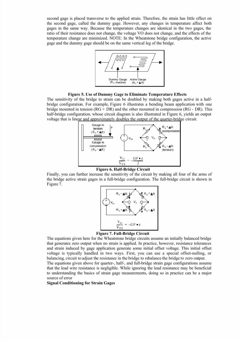
second gage is placed transverse to the applied strain. Therefore, the strain has little effect onthe second gage, called the dummy gage. However, any changes in temperature affect bothgages in the same way. Because the temperature changes are identical in the two gages, the
ratio of their resistance does not change, the voltage VO does not change, and the effects of thetemperature change are minimized. NOTE: In the Wheatstone bridge configuration, the activegage and the dummy gage should be on the same vertical leg of the bridge.
Figure 5. Use of Dummy Gage to Eliminate Temperature Effects
The sensitivity of the bridge to strain can be doubled by making both gages active in a half-
bridge configuration. For example, Figure 6 illustrates a bending beam application with one bridge mounted in tension (RG + DR) and the other mounted in compression (RG - DR). Thishalf-bridge configuration, whose circuit diagram is also illustrated in Figure 6, yields an output
voltage that is linear and approximately doubles the output of the quarter-bridge circuit.
Figure 6. Half-Bridge Circuit
Finally, you can further increase the sensitivity of the circuit by making all four of the arms of
the bridge active strain gages in a full-bridge configuration. The full-bridge circuit is shown inFigure 7.
Figure 7. Full-Bridge Circuit
The equations given here for the Wheatstone bridge circuits assume an initially balanced bridgethat generates zero output when no strain is applied. In practice, however, resistance tolerancesand strain induced by gage application generate some initial offset voltage. This initial offsetvoltage is typically handled in two ways. First, you can use a special offset-nulling, or
balancing, circuit to adjust the resistance in the bridge to rebalance the bridge to zero output.The equations given above for quarter-, half-, and full-bridge strain gage configurations assumethat the lead wire resistance is negligible. While ignoring the lead resistance may be beneficialto understanding the basics of strain gage measurements, doing so in practice can be a majorsource of error
Signal Conditioning for Strain Gages

8/13/2019 Stress and Str
http://slidepdf.com/reader/full/stress-and-str 9/14
Strain gage measurement involves sensing extremely small changes in resistance.Therefore, proper selection and use of the bridge, signal conditioning, wiring, and dataacquisition components are required for reliable measurements. To ensure accurate strain
measurements, it is important to consider the following: Bridge completion
Excitation
Remote sensing Amplification
Filtering Offset
Shunt calibration
Bridge Completion – Unless you are using a full-bridge strain gage sensor with four active
gages, you need to complete the bridge with reference resistors. Therefore, strain gage signalConditioners typically provide half-bridge completion networks consisting of high-precision
reference resistors. Figure 9a shows the wiring of a half-bridge strain gage circuit to aconditioner with completion resistors R1 and R2.
Figure 9a. Connection of Half-Bridge Strain Gage Circuit
Excitation – Strain gage signal conditioners typically provide a constant voltage source to power the bridge. While there is no standard voltage level that is recognized industry wide,
excitation voltage levels of around 3 and 10 V are common. While a higher excitation voltagegenerates a proportionately higher output voltage, the higher voltage can also cause larger
errors because of self-heating.
Remote Sensing – If the strain gage circuit is located a distance away from the signalconditioner and excitation source, a possible source of error is voltage drop caused byresistance in the wires connecting the excitation voltage to the bridge. Therefore, some signal
conditioners include a feature called remote sensing to compensate for this error. Remote sensewires are connected to the point where the excitation voltage wires connect to the bridge circuit,as seen in Figure 9b. The extra sense wires serve to regulate the excitation supply throughnegative feedback amplifiers to compensate for lead losses and deliver the needed voltage at the
bridge.
Figure 9b. Remote Sensor Error CompensationAmplification – The output of strain gages and bridges is relatively small. In practice, most
strain gage bridges and strain-based transducers output less than 10 mV/V (10 mV of output per

8/13/2019 Stress and Str
http://slidepdf.com/reader/full/stress-and-str 10/14
volt of excitation voltage). With 10 V excitation, the output signal is 100 mV. Therefore, straingage signal conditioners usually include amplifiers to boost the signal level to increasemeasurement resolution and improve signal-to-noise ratios.
Filtering – Strain gages are often located in electrically noisy environments. It is thereforeessential to be able to eliminate noise that can couple to strain gages. Lowpass filters, whenused with strain gages, can remove the high-frequency noise prevalent in most environmentalsettings.
Offset Nulling – When a bridge is installed, it is very unlikely that the bridge will outputexactly zero volts when no strain is applied. Slight variations in resistance among the bridgearms and lead resistance will generate some nonzero initial offset voltage. Offset nulling can be
performed by either hardware or software:
1. Software Compensation – With this method, you take an initial measurement before straininput is applied, and use this offset to compensate subsequent measurements. This method is
simple,fast, and requires no manual adjustments. The disadvantage of the software compensationmethod is that the offset of the bridge is not removed. If the offset is large enough, it limits the
amplifier gain you can apply to the output voltage, thus limiting the dynamic range of themeasurement.
2. Offset-Nulling Circuit – The second balancing method uses an adjustable resistance, a potentiometer, to physically adjust the output of the bridge to zero. By varying the resistance of potentiometer, you can control the level of the bridge output and set the initial output to zero
volts.
Shunt Calibration – The normal procedure to verify the output of a strain gage measurementsystem relative to some predetermined mechanical input or strain is called shunt calibration.Shunt calibration involves simulating the input of strain by changing the resistance of an arm inthe bridge by some known amount. This is accomplished by shunting, or connecting, a largeresistor of known value (Rs) across one arm of the bridge, creating a known DR as seen in
Figure 9c. The output of the bridge can then be measured and compared to the expected voltagevalue. The results are used to correct span errors in the entire measurement path, or to simply
verify general operation to gain confidence in the setup.
Figure 9c. Shunt Resistor Connected Across R3
Data Acquisition System
Strain gauge rosette:
A strain gauge rosette is, by definition, an arrangement of two or more closely positioned gagegrids, separately oriented to measure the normal strains along different directions in theunderlying surface of the test part. Rosettes are designed to perform a very practical and
important function in experimental stress analysis. It can be shown that for the not-uncommoncase of the general biaxial stress state, with the principal directions unknown, three independentstrain measurements (in different directions) are required to determine the principal strains and

8/13/2019 Stress and Str
http://slidepdf.com/reader/full/stress-and-str 11/14
stresses. And even when the principal directions are known in advance, two independent strainmeasurements are needed to obtain the principal strains and stresses.To meet the foregoing requirements, the Micro-Measurements Division manufactures three
basic types of strain gage rosettes (each in a variety of forms):
Tee (0-90 degree)Two mutually perpendicular grids.
Rectangular (0-45-90 degree)
Three grids, with the second and third grids angularly displaced from the first grid by 45 degrees and 90 degrees, respectively.
Delta (0-60-120 degree)
Three grids, with the second and third grids 60 degrees and 120 degrees away,respectively, from the first grid.
Positioning strain gages to monitor bending, axial, shear, and torsion loads: G
“strain” is defined as the ratio of the change in length to the initial unstressed reference length.
A strain gage is the element that senses this change and converts it into an electrical signal. Thiscan be accomplished because a strain gage changes resistance as it is stretched, or compressed,similar to wire. The important factors that must be considered before selecting a strain gage arethe direction, type, and resolution of the strain you wish to measure. To measure minute strains,
the user must be able to measure minute resistance changes. The Wheatstone Bridgeconfiguration, shown in Figure B, is capable of measuring these small resistance changes. Note
the signs associated with each gage numbered 1 through 4. The total strain is always the sum ofthe four strains. M
The total strain is represented by a change in VOUT. If each gage had the same positive strain,the total would be zero and VOUT would remain unchanged. Bending, axial, and shear strainare the most common types of strain measured. The actual arrangement of your strain gages
will determine the type of strain you can measure and the output voltage change. See Figures Cthrough F. For example, if a positive (tensile) strain is applied to gages 1 and 3, and a negative
(compressive) strain to gages 2 and 4, the total strainwould be 4 times the strain on one gage. See
Figure C. If total strain is four times the strain on one gage, this means that the output will be fourtimes larger. Therefore, greater sensitivity and resolution are possible when more than one straingage is used. The following equations show the relationships among stress, strain, and force forbending, axial, shear, and torsional strain.
1) BENDING STRAIN or moment strain is equal to bending stress divided by Young’s Modulus ofElasticity.
Moment stress (oB) equals bending moment (Fn x l ) divided by sectional modulus. Sectional
modulus (Z) is a property of the cross-sectional configuration of the specimen. For rectangles only,the the sectional modulus is bh2/6). Strain gages used in the bending strain configuration can be
used to determine vertical load (Fn); this is more commonly referred to as a bending beam load cell.
Fn = E eB(Z)/l = E eB(bh2 ⁄ 6)/l
2) AXIAL STRAIN equals axial stress divided by Young’s Modulus. EA = oA/E oA = FA/AWhere axial stress (oA) equals the axial load divided by the cross-sectional area. The crosssectionalarea for rectangles equals (b x d). Therefore, strain gages used in axial configurations can be used
to determine axial loads (F (axial)). F (axial) = EeAbh

8/13/2019 Stress and Str
http://slidepdf.com/reader/full/stress-and-str 12/14
g = t/G t = Fn x Q/bI
Where shear stress (t) equals (Q), the moment of area about the neutral axis multiplied by the
vertical load (Fn) divided by the thickness (b) and the moment of
inertia ( I ). Both the moment of area (Q) and the moment of inertia ( I ) are functions of the
specimen’s cross-sectional geometry. For rectangles only Q = bh2 ⁄ 8 and I = bh3 ⁄ 12 The shear strain (g)
is determined by measuring the strain at a 45° angle, as shown in Figure E.
g = 2 X e@ 45°
The modulus of shear strain (G) = E/2 (1 +m). Therefore, strain gages used in a shear strain
configuration can be used to determine vertical loads (Fn); this is more commonly referred to as a
shear beam load cell.
Fn = G (g) bI/Q
= G (g) b (bh3 ⁄ 12)/(bh2 ⁄ 8)
= G (g)bh(2/3)4) TORSIONAL STRAIN equals
torsional stress (t) divided by
torsional modulus of elasticity (G).See Figure F.
g = 2 x e@ 45° = t/Gt = Mt(d/2)/J

8/13/2019 Stress and Str
http://slidepdf.com/reader/full/stress-and-str 13/14
where torsional stress (t) equalstorque (Mt) multiplied by the distance from the center of the section
to the outer fiber (d/2), divided by (J), the polar moment of inertia. The polar moment of inertia is a
function of the crosssectional area. For solid circular shafts only, J =p(d)4 ⁄ 32. The modulus of shear
strain (G) has been defined in the preceding discussion on shear stress. Strain gages can be usedto determine torsional moments as shown in the equation below. This represents the principlebehind every torque sensor.
Mt = t(J) (2/d) = gG (J) (2/d) = gG (pd 3 ⁄ 16)
Ø = MTL/G(J)
Figure 1: Torque on a Rotating Shaft
Torque Measurement:
Torque is measured by either sensing the actual shaft deflection caused by a twisting force, or by detecting the effects of this deflection. The surface of a shaft under torque will experiencecompression and tension, as shown in Figure 1. To measure torque, strain gage elementsusually are mounted in pairs on the shaft, one gauge measuring the increase in length (in the
direction in which the surface is under tension), the other measuring The decrease in length inthe other direction. Early torque sensors consisted of mechanical structures fitted with straingages. Their high cost and low reliability kept them from gaining general industrial acceptance.
Modern technology, however, has lowered the cost of making torque measurements, whilequality controls on production have increased the need for accurate torque measurement.
Torque Application
Applications for torque sensors include determining the amount of power an engine, motor,turbine, or other rotating device generates or consumes. In the industrial world, ISO 9000 andother quality control specifications are now requiring companies to measure torque during
manufacturing, especially when fasteners are applied. Sensors make the required torquemeasurements automatically on screw and assembly machines, and can be added to hand tools.
In both cases, the collected data can be accumulated on dataloggers for quality control andreporting purposes.Other industrial applications of torque sensors include measuring metalremoval rates in machine tools; the calibration of torque tools and sensors; measuring peelforces, friction, and bottle cap torque; testing springs; and making biodynamic measurements.

8/13/2019 Stress and Str
http://slidepdf.com/reader/full/stress-and-str 14/14
Sensor configurations
Torque can be measured by rotating strain gages as well as by stationary proximity,magnetostrictive, and magnetoelastic sensors. All are temperature sensitive. Rotary sensorsmust be mounted on the shaft, which may not always be possible because of space limitations.
Figure2 : Inductive Coupling of Torque Sensors
A strain gage can be installed directly on a shaft. Because the shaft is rotating, the torque sensorcan be connected to its power source and signal conditioning electronics via a slip ring. Thestrain gage also can be connected via a transformer, eliminating the need for high maintenance
slip rings. The excitation voltage for the strain gage is inductively coupled, and the strain gageoutput is converted to a modulated pulse frequency (Figure 2). Maximum speed of such anarrangement is 15,000 rpm.Strain gages also can be mounted on stationary support members or on the housing itself.
These "reaction" sensors measure the torque that is transferred by the shaft to the restraining
elements. The resultant reading is not completely accurate, as it disregards the inertia of themotor.
Strain gages used for torque measurements include foil, diffused semiconductor, and thin filmtypes. These can be attached directly to the shaft by soldering or adhesives. If the centrifugalforces are not large--and an out-of-balance load can be tolerated--the associated electronics,
including battery, amplifier, and radio frequency transmitter all can be strapped to the shaft.


![[XLS] · Web viewSTR 20015 STR 30105 STR 30115 STR 30123 STR 30125 STR 30130 STR 40090 ORİ STR 40115 STR 41090 ORİ STR 44115 STR 45111 STR 50020 STR 50103A STR 50112 STR 50113A](https://img.pdfslide.net/doc/110x75/5ad04b0c7f8b9a1d328e1e93/xls-viewstr-20015-str-30105-str-30115-str-30123-str-30125-str-30130-str-40090.jpg)