Embed Size (px)
Citation preview
Page 1 of 10
4-Stroke IDI Turbocharged Diesel Snowmobile Design
Clean Snowmobile Challenge 2017 Design Paper
Charles-Philippe Aubin, Etienne Girard, Pierre-Olivier Langlois, Yoan Lebreux, Guillaume Verner
École de technologie supérieure (ÉTS)
Copyright © 2017 SAE International
ABSTRACT
As engineering students from the snowmobile’s
origin province, Team QUIETS has decided to take
on the challenge of modifying and improving the
image of this vehicle. With growing concerns
regarding emissions controls and noise from
recreational vehicles such as the snowmobile, we
are using a 2017 Ski-Doo Tundra chassis with a
Kohler KDW1003 diesel engine for our researches.
Our modifications include the implementation of a
turbocharger, an entirely redesigned exhaust system
and exhaust after treatment solutions. These
modifications will allow our snowmobile to
compete in the diesel utility class and attempt to
justify the need for diesel snowmobiles in today’s
market. The modified snowmobile now has a peak
power output of 40hp and 70ft-lbs of torque. Many
other modifications concerning the rest of the
vehicle will also be presented. This student club is
a great example of what a group of 22 students with
common goals can accomplish.
INTRODUCTION
Team QUIETS is proud to present our 2017 Clean
Snowmobile Challenge submission for the DUC.
This year, we took on the challenge of designing
and building a second snowmobile. Seeing the
growing interest for diesel powered UTVs, it seems
inevitable that diesel utility snowmobiles will also
appear on the market in the near future. With this in
mind, we were set on showing the world our team’s
view of what a diesel snowmobile should be like.
We believe that this new platform will open up a
plethora of possibilities for future modifications and
improvements. Many of the advantages of the diesel
engine make it a great powertrain for a utility
snowmobile - namely, the high torque output as
well as low noise and great fuel economy. We also
believe that this year’s project is considerably more
economically viable than its predecessors, as it
relies more on readily available components and
high-value modifications. We have accomplished a
lot in a relatively short time, and we look forward to
show our improvement at the CSC 2017.
SNOWMOBILE BASE CHASSIS SELECTION
Tundra Sport
As we were starting a new year with a new project,
we had the chance to choose the body on which we
would build our prototype. Our choice was based on
three main criteria. First, it had to be a BRP because
they’re built in our province and we’re proud of
that. Second, it had to be a utility snowmobile.
Finally, it had to be the most fuel economical
design.
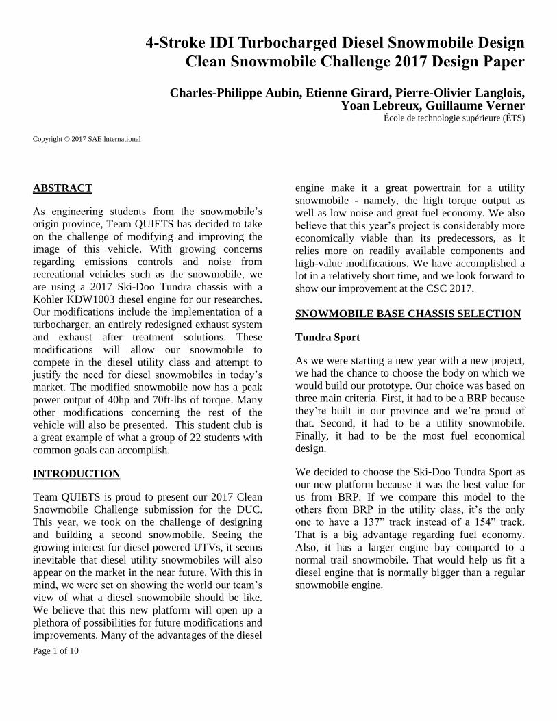
We decided to choose the Ski-Doo Tundra Sport as
our new platform because it was the best value for
us from BRP. If we compare this model to the
others from BRP in the utility class, it’s the only
one to have a 137” track instead of a 154” track.
That is a big advantage regarding fuel economy.
Also, it has a larger engine bay compared to a
normal trail snowmobile. That would help us fit a
diesel engine that is normally bigger than a regular
snowmobile engine.
Page 2 of 10
Figure 1, Tundra Sport vs Tundra LT
LTS front suspension
The LTS front suspension is the typical front
suspension offered by BRP for their utility
snowmobiles. They are easy to adjust and work
with compared to conventional trail suspension
because the only thing you can adjust is the preload
of the springs. This reduces the versatility of the
suspension but the dampening is usually acceptable
for a utility snowmobile. We’ve decided to change
the springs for stiffer ones because of the extra
weight of the diesel engine, turbo and other
modifications in the front part of the snowmobile.
The compression rate of the new springs is 90lbs/in
which is almost 30% stiffer than the stock ones. We
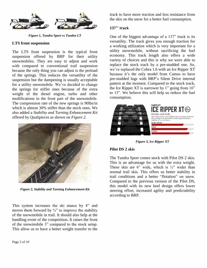
also added a Stability and Turning Enhancement Kit
offered by Qualipieces as shown on Figure 2.
Figure 2, Stability and Turning Enhancement Kit
This system increases the ski stance by 4” and
moves them forward by ¾” to improve the stability
of the snowmobile in trail. It should also help at the
handling event of the competition. It raises the front
of the snowmobile 3” compared to the stock setup.
This allow us to have a better weight transfer to the
track to have more traction and less resistance from
the skis on the snow for a better fuel consumption.
137’’ track
One of the biggest advantage of a 137” track is its
versatility. The track gives you enough traction for
a working utilization which is very important for a
utility snowmobile, without sacrificing the fuel
economy. This track length also offers a wide
variety of choices and this is why we were able to
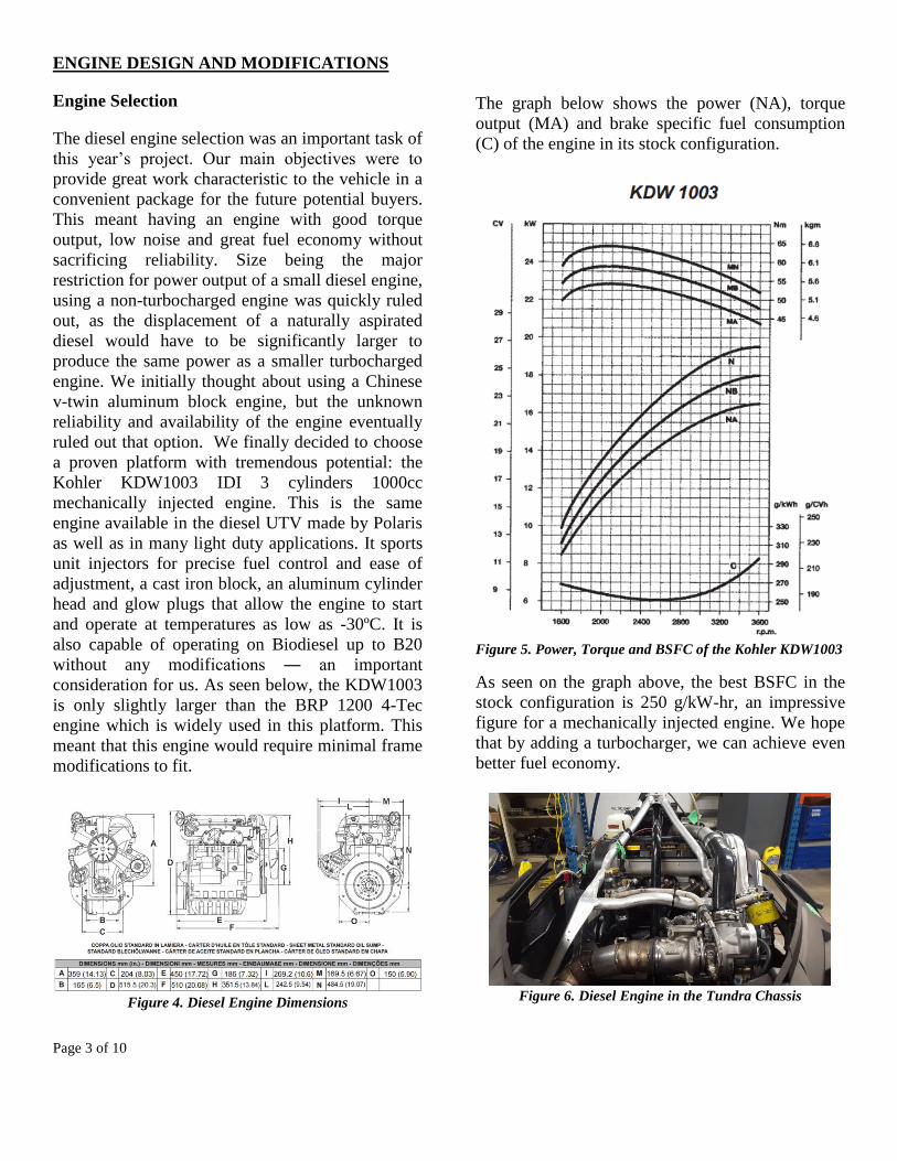
replace the stock track by a pre-studded one. So,
we’ve replaced the Cobra 1.6 with an Ice Ripper XT
because it’s the only model from Camso to have
pre-studded lugs with BRP’s Silent Drive internal
pattern at the moment. Compared to the stock track,
the Ice Ripper XT is narrower by 1” going from 16”
to 15”. We believe this will help us reduce the fuel
consumption.
Figure 3, Ice Ripper XT
Pilot DS 2 skis
The Tundra Sport comes stock with Pilot DS 2 skis.
This is an advantage for us with the extra weight.
These skis are 6” wide, which is ½” wider than
normal trail skis. This offers us better stability in
trail conditions and a better “flotation” on snow.
Compared to the previous version of the Pilot DS,
this model with its new keel design offers lower
steering effort, increased agility and predictability
according to BRP.
Page 3 of 10
ENGINE DESIGN AND MODIFICATIONS
Engine Selection
The diesel engine selection was an important task of
this year’s project. Our main objectives were to
provide great work characteristic to the vehicle in a
convenient package for the future potential buyers.
This meant having an engine with good torque
output, low noise and great fuel economy without
sacrificing reliability. Size being the major
restriction for power output of a small diesel engine,
using a non-turbocharged engine was quickly ruled
out, as the displacement of a naturally aspirated
diesel would have to be significantly larger to
produce the same power as a smaller turbocharged
engine. We initially thought about using a Chinese
v-twin aluminum block engine, but the unknown
reliability and availability of the engine eventually
ruled out that option. We finally decided to choose
a proven platform with tremendous potential: the
Kohler KDW1003 IDI 3 cylinders 1000cc
mechanically injected engine. This is the same
engine available in the diesel UTV made by Polaris
as well as in many light duty applications. It sports
unit injectors for precise fuel control and ease of
adjustment, a cast iron block, an aluminum cylinder
head and glow plugs that allow the engine to start
and operate at temperatures as low as -30ºC. It is
also capable of operating on Biodiesel up to B20
without any modifications ― an important
consideration for us. As seen below, the KDW1003
is only slightly larger than the BRP 1200 4-Tec
engine which is widely used in this platform. This
meant that this engine would require minimal frame
modifications to fit.
Figure 4. Diesel Engine Dimensions
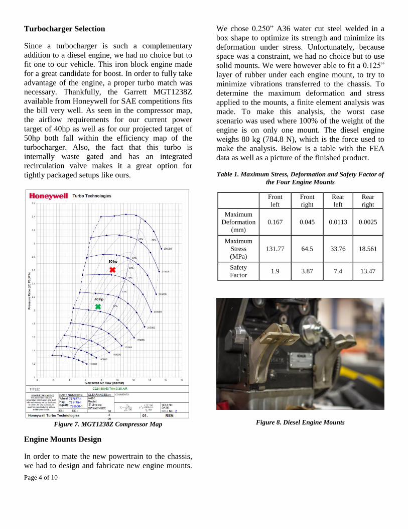
The graph below shows the power (NA), torque
output (MA) and brake specific fuel consumption
(C) of the engine in its stock configuration.
Figure 5. Power, Torque and BSFC of the Kohler KDW1003
As seen on the graph above, the best BSFC in the
stock configuration is 250 g/kW-hr, an impressive
figure for a mechanically injected engine. We hope
that by adding a turbocharger, we can achieve even
better fuel economy.
Figure 6. Diesel Engine in the Tundra Chassis
Page 4 of 10
Turbocharger Selection
Since a turbocharger is such a complementary
addition to a diesel engine, we had no choice but to
fit one to our vehicle. This iron block engine made
for a great candidate for boost. In order to fully take
advantage of the engine, a proper turbo match was
necessary. Thankfully, the Garrett MGT1238Z
available from Honeywell for SAE competitions fits
the bill very well. As seen in the compressor map,
the airflow requirements for our current power
target of 40hp as well as for our projected target of
50hp both fall within the efficiency map of the
turbocharger. Also, the fact that this turbo is
internally waste gated and has an integrated
recirculation valve makes it a great option for
tightly packaged setups like ours.
Figure 7. MGT1238Z Compressor Map
Engine Mounts Design
In order to mate the new powertrain to the chassis,
we had to design and fabricate new engine mounts.
We chose 0.250” A36 water cut steel welded in a
box shape to optimize its strength and minimize its
deformation under stress. Unfortunately, because
space was a constraint, we had no choice but to use
solid mounts. We were however able to fit a 0.125”
layer of rubber under each engine mount, to try to
minimize vibrations transferred to the chassis. To
determine the maximum deformation and stress
applied to the mounts, a finite element analysis was
made. To make this analysis, the worst case
scenario was used where 100% of the weight of the
engine is on only one mount. The diesel engine
weighs 80 kg (784.8 N), which is the force used to
make the analysis. Below is a table with the FEA
data as well as a picture of the finished product.
Table 1. Maximum Stress, Deformation and Safety Factor of
the Four Engine Mounts
Front
left
Front
right
Rear
left
Rear
right
Maximum
Deformation
(mm)
0.167 0.045 0.0113 0.0025
Maximum
Stress
(MPa)
131.77 64.5 33.76 18.561
Safety
Factor 1.9 3.87 7.4 13.47
Figure 8. Diesel Engine Mounts
Page 5 of 10
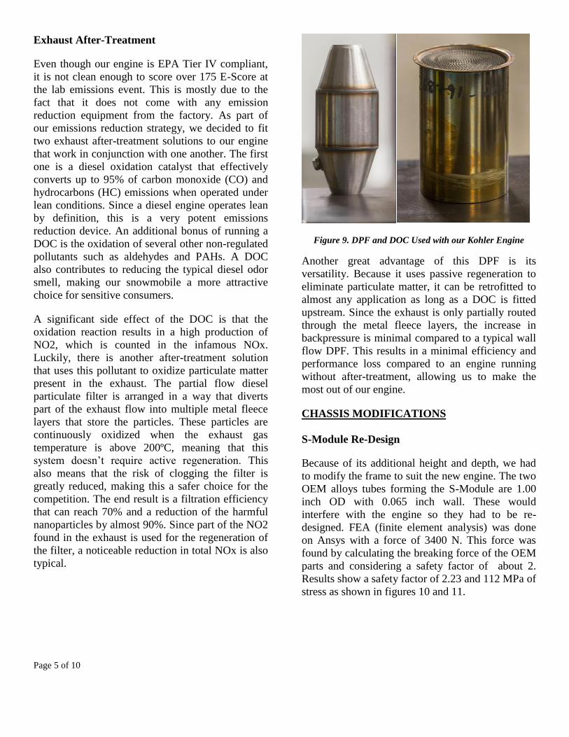
Exhaust After-Treatment
Even though our engine is EPA Tier IV compliant,
it is not clean enough to score over 175 E-Score at
the lab emissions event. This is mostly due to the
fact that it does not come with any emission
reduction equipment from the factory. As part of
our emissions reduction strategy, we decided to fit
two exhaust after-treatment solutions to our engine
that work in conjunction with one another. The first
one is a diesel oxidation catalyst that effectively
converts up to 95% of carbon monoxide (CO) and
hydrocarbons (HC) emissions when operated under
lean conditions. Since a diesel engine operates lean
by definition, this is a very potent emissions
reduction device. An additional bonus of running a
DOC is the oxidation of several other non-regulated
pollutants such as aldehydes and PAHs. A DOC
also contributes to reducing the typical diesel odor
smell, making our snowmobile a more attractive
choice for sensitive consumers.
A significant side effect of the DOC is that the
oxidation reaction results in a high production of
NO2, which is counted in the infamous NOx.
Luckily, there is another after-treatment solution
that uses this pollutant to oxidize particulate matter
present in the exhaust. The partial flow diesel
particulate filter is arranged in a way that diverts
part of the exhaust flow into multiple metal fleece
layers that store the particles. These particles are
continuously oxidized when the exhaust gas
temperature is above 200ºC, meaning that this
system doesn’t require active regeneration. This
also means that the risk of clogging the filter is
greatly reduced, making this a safer choice for the
competition. The end result is a filtration efficiency
that can reach 70% and a reduction of the harmful
nanoparticles by almost 90%. Since part of the NO2
found in the exhaust is used for the regeneration of
the filter, a noticeable reduction in total NOx is also
typical.
Figure 9. DPF and DOC Used with our Kohler Engine
Another great advantage of this DPF is its
versatility. Because it uses passive regeneration to
eliminate particulate matter, it can be retrofitted to
almost any application as long as a DOC is fitted
upstream. Since the exhaust is only partially routed
through the metal fleece layers, the increase in
backpressure is minimal compared to a typical wall
flow DPF. This results in a minimal efficiency and
performance loss compared to an engine running
without after-treatment, allowing us to make the
most out of our engine.
CHASSIS MODIFICATIONS
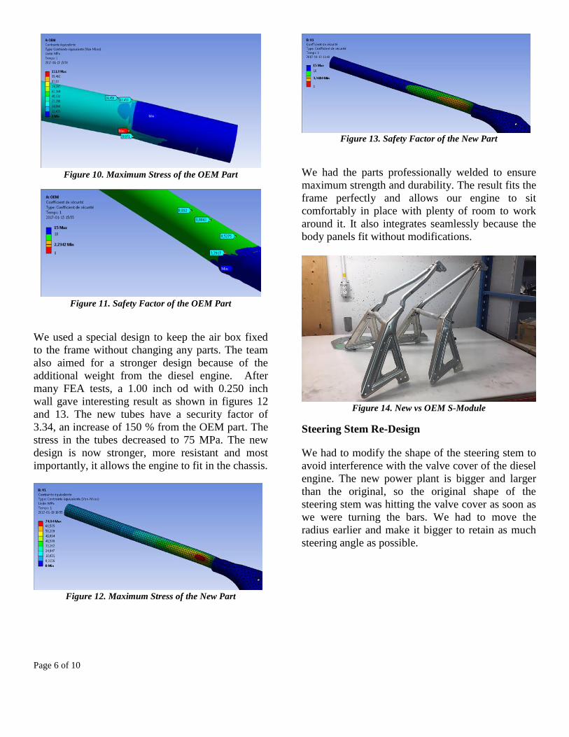
S-Module Re-Design
Because of its additional height and depth, we had
to modify the frame to suit the new engine. The two
OEM alloys tubes forming the S-Module are 1.00
inch OD with 0.065 inch wall. These would
interfere with the engine so they had to be re-
designed. FEA (finite element analysis) was done
on Ansys with a force of 3400 N. This force was
found by calculating the breaking force of the OEM
parts and considering a safety factor of about 2.
Results show a safety factor of 2.23 and 112 MPa of
stress as shown in figures 10 and 11.
Page 6 of 10
Figure 10. Maximum Stress of the OEM Part
Figure 11. Safety Factor of the OEM Part
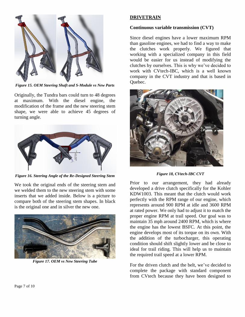
We used a special design to keep the air box fixed
to the frame without changing any parts. The team
also aimed for a stronger design because of the
additional weight from the diesel engine. After
many FEA tests, a 1.00 inch od with 0.250 inch
wall gave interesting result as shown in figures 12
and 13. The new tubes have a security factor of
3.34, an increase of 150 % from the OEM part. The
stress in the tubes decreased to 75 MPa. The new
design is now stronger, more resistant and most
importantly, it allows the engine to fit in the chassis.
Figure 12. Maximum Stress of the New Part
Figure 13. Safety Factor of the New Part
We had the parts professionally welded to ensure
maximum strength and durability. The result fits the
frame perfectly and allows our engine to sit
comfortably in place with plenty of room to work
around it. It also integrates seamlessly because the
body panels fit without modifications.
Figure 14. New vs OEM S-Module
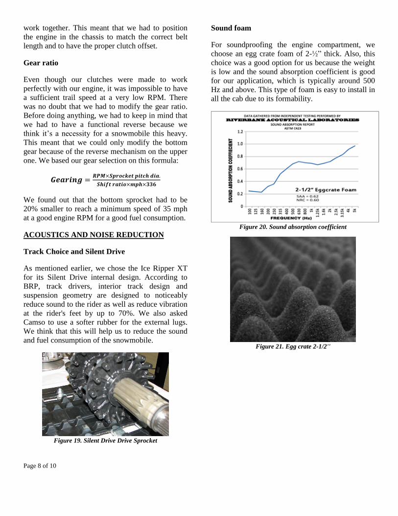
Steering Stem Re-Design
We had to modify the shape of the steering stem to
avoid interference with the valve cover of the diesel
engine. The new power plant is bigger and larger
than the original, so the original shape of the
steering stem was hitting the valve cover as soon as
we were turning the bars. We had to move the
radius earlier and make it bigger to retain as much
steering angle as possible.
Page 7 of 10
Figure 15. OEM Steering Shaft and S-Module vs New Parts
Originally, the Tundra bars could turn to 48 degrees
at maximum. With the diesel engine, the
modification of the frame and the new steering stem
shape, we were able to achieve 45 degrees of
turning angle.
Figure 16. Steering Angle of the Re-Designed Steering Stem
We took the original ends of the steering stem and
we welded them to the new steering stem with some
inserts that we added inside. Below is a picture to
compare both of the steering stem shapes. In black
is the original one and in silver the new one.
Figure 17. OEM vs New Steering Tube
DRIVETRAIN
Continuous variable transmission (CVT)
Since diesel engines have a lower maximum RPM
than gasoline engines, we had to find a way to make
the clutches work properly. We figured that
working with a specialized company in this field
would be easier for us instead of modifying the
clutches by ourselves. This is why we’ve decided to
work with CVtech-IBC, which is a well known
company in the CVT industry and that is based in
Quebec.
Figure 18, CVtech-IBC CVT
Prior to our arrangement, they had already
developed a drive clutch specifically for the Kohler
KDW1003. This meant that the clutch would work
perfectly with the RPM range of our engine, which
represents around 900 RPM at idle and 3600 RPM
at rated power. We only had to adjust it to match the
proper engine RPM at trail speed. Our goal was to
maintain 35 mph around 2400 RPM, which is where
the engine has the lowest BSFC. At this point, the
engine develops most of its torque on its own. With
the addition of the turbocharger, this operating
condition should shift slightly lower and be close to
ideal for trail riding. This will help us to maintain
the required trail speed at a lower RPM.
For the driven clutch and the belt, we’ve decided to
complete the package with standard component
from CVtech because they have been designed to
Page 8 of 10
work together. This meant that we had to position
the engine in the chassis to match the correct belt
length and to have the proper clutch offset.
Gear ratio
Even though our clutches were made to work
perfectly with our engine, it was impossible to have
a sufficient trail speed at a very low RPM. There
was no doubt that we had to modify the gear ratio.
Before doing anything, we had to keep in mind that
we had to have a functional reverse because we
think it’s a necessity for a snowmobile this heavy.
This meant that we could only modify the bottom
gear because of the reverse mechanism on the upper
one. We based our gear selection on this formula:
𝑮𝒆𝒂𝒓𝒊𝒏𝒈 =𝑹𝑷𝑴×𝑺𝒑𝒓𝒐𝒄𝒌𝒆𝒕 𝒑𝒊𝒕𝒄𝒉 𝒅𝒊𝒂.
𝑺𝒉𝒊𝒇𝒕 𝒓𝒂𝒕𝒊𝒐×𝒎𝒑𝒉×𝟑𝟑𝟔
We found out that the bottom sprocket had to be
20% smaller to reach a minimum speed of 35 mph
at a good engine RPM for a good fuel consumption.
ACOUSTICS AND NOISE REDUCTION
Track Choice and Silent Drive
As mentioned earlier, we chose the Ice Ripper XT
for its Silent Drive internal design. According to
BRP, track drivers, interior track design and
suspension geometry are designed to noticeably
reduce sound to the rider as well as reduce vibration
at the rider's feet by up to 70%. We also asked
Camso to use a softer rubber for the external lugs.
We think that this will help us to reduce the sound
and fuel consumption of the snowmobile.
Figure 19. Silent Drive Drive Sprocket
Sound foam
For soundproofing the engine compartment, we
choose an egg crate foam of 2-½” thick. Also, this
choice was a good option for us because the weight
is low and the sound absorption coefficient is good
for our application, which is typically around 500
Hz and above. This type of foam is easy to install in
all the cab due to its formability.
Figure 20. Sound absorption coefficient
Figure 21. Egg crate 2-1/2''
Page 9 of 10
SUMMARY/CONCLUSIONS
Our new endeavor, the diesel-powered Tundra is a
great project that’s aimed at proving the need for
DUC snowmobiles in today’s market. By offering
great low-end torque, low fuel consumption and
good work characteristics, a snowmobile of this
kind makes for a great replacement to a UTV for
winter outdoor work. Our team’s vehicle is quiet,
efficient and reliable, which makes it a robust
alternative. The perfect transmission match and
upgraded suspension makes it a great trail sled as
well, showing the multiple capabilities of this
vehicle. We look forward to hearing feedback from
the judges and riders this first year, as we strive to
improve the upcoming prototypes.
REFERENCES
1. Çengel, Y.A., Boles, M.A.
"Thermodynamics: An Engineering
Approach", 8 Edition, McGraw-Hill,
Montréal.
2. "Snowmobile track warehouse", consulted
on February 15, 2017,
http://www.snowmobiletrackwarehouse.com
/category/7890/ice-ripper-xt
3. Çengel, Y. A. & Cimbala, J. M. 2014 "Fluid
Mechanics: Fundamentals and
Applications", 3nd Edition, McGraw-Hill,
New-York.
4. Levendis Y A, Pavalatos I, Abrams R F
"1994 Control of diesel soot hydrocarbon
and NOx emissions with a particular trap."
SAE Technical Paper 940460
5. Miller, J. and C. Bowman. "Mechanism and
modeling of nitrogen chemistry in
combustion: Prog Energy" Combustion. Sci.
15, 287-338, 1989
6. Willard W. Pulkrabek, "Engineering
Fundamentals of the Internal Combustion
Engine", University of Wisconsin: Prentice
Hall
7. AAEN O. “Clutch Tuning Handbook”, 2009
Updated Edition (Original 1986), AAEN
Performance, 76 pages.
8. Emitec, “Partial Flow Diesel Particulate
Filters (P-DPF) are Easy to Retrofit”, 2009,
Press Release. Consulted on Februrary 19th
2017,
http://www.emitec.com/fileadmin/user_uplo
ad/Presse/Archiv/Presseinformationen/Diese
l_particulate_filter_engl.pdf
Page 10 of 10
DEFINITIONS/ABBREVIATIONS
CO Carbon Monoxide
CO2 Carbon Dioxide
CVT Continuous Variable Transmission
DOC Diesel Oxidation Catalyst
DPF Diesel Particulate Filter
EGT Exhaust Gas Temperature
HC Hydro Carbon
H2O Hydrogen Dioxide
Hz Hertz
MPH Miles per hour
NOx Different groups of nitrous oxides
RPM Rotations per minute
AKI Anti-knock index, also known as PON (Posted Octane Number)
DUC Diesel Utility Class