Embed Size (px)
Citation preview
CMPE550 CMPE550 -- ShaabanShaaban#1 Lec # 2 Spring 2019 1-23-2019
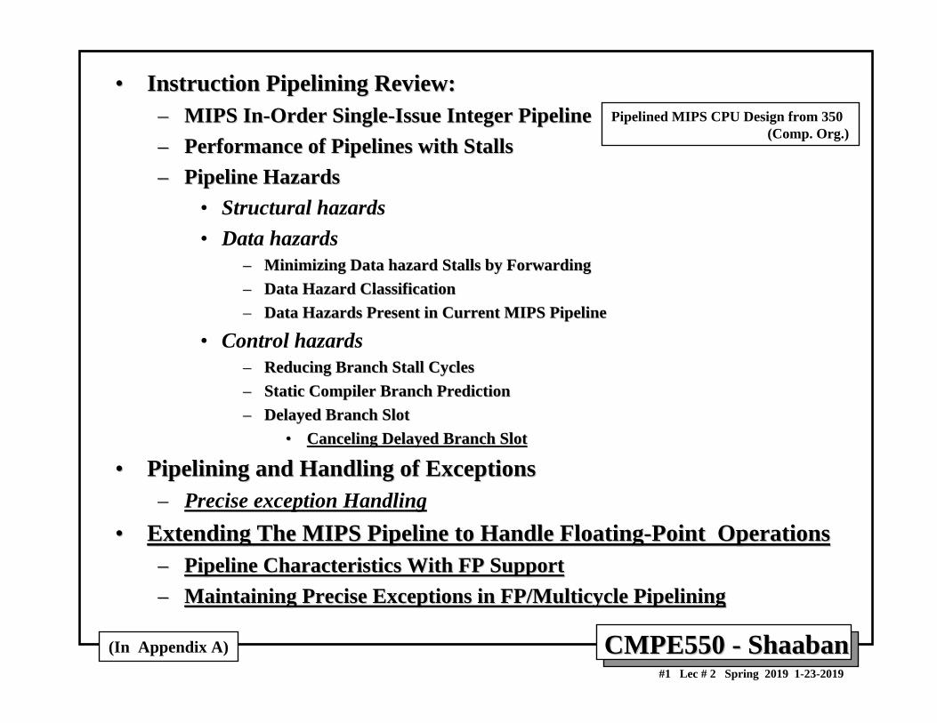
•• Instruction Pipelining Review:Instruction Pipelining Review:–– MIPS InMIPS In--Order SingleOrder Single--Issue Integer PipelineIssue Integer Pipeline–– Performance of Pipelines with StallsPerformance of Pipelines with Stalls–– Pipeline HazardsPipeline Hazards
• Structural hazards• Data hazards
–– Minimizing Data hazard Stalls by ForwardingMinimizing Data hazard Stalls by Forwarding–– Data Hazard ClassificationData Hazard Classification–– Data Hazards Present in Current MIPS PipelineData Hazards Present in Current MIPS Pipeline
• Control hazards–– Reducing Branch Stall CyclesReducing Branch Stall Cycles–– Static Compiler Branch PredictionStatic Compiler Branch Prediction–– Delayed Branch SlotDelayed Branch Slot
•• Canceling Delayed Branch SlotCanceling Delayed Branch Slot
•• Pipelining and Handling of ExceptionsPipelining and Handling of Exceptions– Precise exception Handling
•• Extending The MIPS Pipeline to Handle FloatingExtending The MIPS Pipeline to Handle Floating--Point OperationsPoint Operations–– Pipeline Characteristics With FP SupportPipeline Characteristics With FP Support–– Maintaining Precise Exceptions in FP/Multicycle PipeliningMaintaining Precise Exceptions in FP/Multicycle Pipelining
(In Appendix A)
Pipelined MIPS CPU Design from 350(Comp. Org.)
CMPE550 CMPE550 -- ShaabanShaaban#2 Lec # 2 Spring 2019 1-23-2019
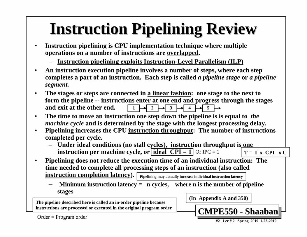
Instruction Pipelining ReviewInstruction Pipelining Review• Instruction pipelining is CPU implementation technique where multiple
operations on a number of instructions are overlapped.– Instruction pipelining exploits Instruction-Level Parallelism (ILP)
• An instruction execution pipeline involves a number of steps, where each step completes a part of an instruction. Each step is called a pipeline stage or a pipeline segment.
• The stages or steps are connected in a linear fashion: one stage to the next to form the pipeline -- instructions enter at one end and progress through the stages and exit at the other end.
• The time to move an instruction one step down the pipeline is is equal to the machine cycle and is determined by the stage with the longest processing delay.
• Pipelining increases the CPU instruction throughput: The number of instructions completed per cycle.
– Under ideal conditions (no stall cycles), instruction throughput is one instruction per machine cycle, or ideal CPI = 1
• Pipelining does not reduce the execution time of an individual instruction: The time needed to complete all processing steps of an instruction (also called instruction completion latency). – Minimum instruction latency = n cycles, where n is the number of pipeline
stages(In Appendix A and 350)
The pipeline described here is called an in-order pipeline because instructions are processed or executed in the original program order
1 2 3 4 5
Pipelining may actually increase individual instruction latency
Order = Program order
Or IPC = 1 T = I x CPI x C
CMPE550 CMPE550 -- ShaabanShaaban#3 Lec # 2 Spring 2019 1-23-2019
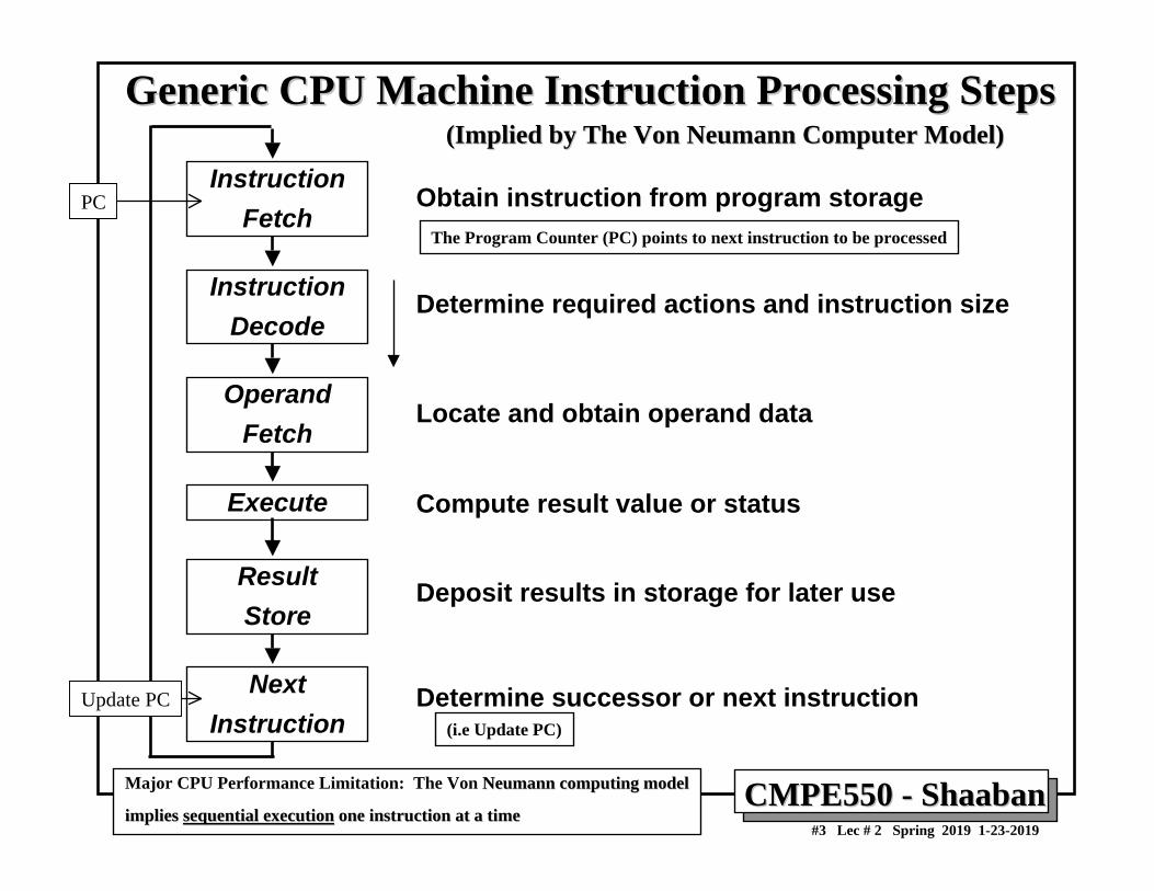
Generic CPU Machine Instruction Processing StepsGeneric CPU Machine Instruction Processing Steps
InstructionFetch
InstructionDecode
OperandFetch
Execute
ResultStore
NextInstruction
Obtain instruction from program storage
Determine required actions and instruction size
Locate and obtain operand data
Compute result value or status
Deposit results in storage for later use
Determine successor or next instruction
(Implied by The Von Neumann Computer Model)(Implied by The Von Neumann Computer Model)
Major CPU Performance Limitation: The Von Neumann computing modelNeumann computing model
implies implies sequential executionsequential execution one instruction at a timeone instruction at a time
The Program Counter (PC) points to next instruction to be processed
(i.e Update PC)
PC
Update PC
CMPE550 CMPE550 -- ShaabanShaaban#4 Lec # 2 Spring 2019 1-23-2019
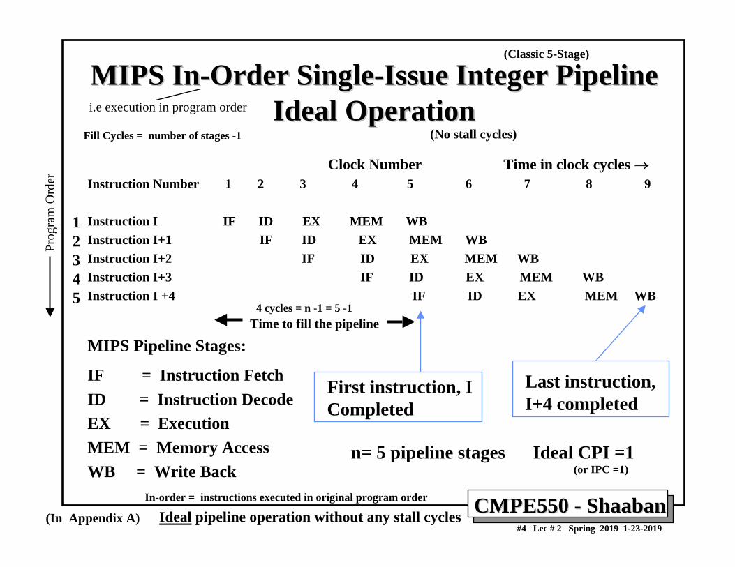
MIPS InMIPS In--Order SingleOrder Single--Issue Integer Pipeline Issue Integer Pipeline Ideal OperationIdeal Operation
Clock Number Time in clock cycles →Instruction Number 1 2 3 4 5 6 7 8 9
Instruction I IF ID EX MEM WBInstruction I+1 IF ID EX MEM WBInstruction I+2 IF ID EX MEM WBInstruction I+3 IF ID EX MEM WBInstruction I +4 IF ID EX MEM WB
Time to fill the pipeline
MIPS Pipeline Stages:
IF = Instruction FetchID = Instruction DecodeEX = ExecutionMEM = Memory AccessWB = Write Back
First instruction, ICompleted
Last instruction, I+4 completed
n= 5 pipeline stages Ideal CPI =1
(In Appendix A)
Fill Cycles = number of stages -1
4 cycles = n -1 = 5 -1
(No stall cycles)
Ideal pipeline operation without any stall cyclesIn-order = instructions executed in original program order
(or IPC =1)
(Classic 5-Stage)Pr
ogra
m O
rder
i.e execution in program order
12345
CMPE550 CMPE550 -- ShaabanShaaban#5 Lec # 2 Spring 2019 1-23-2019
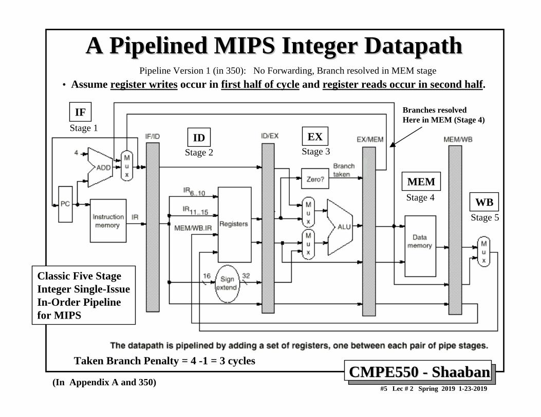
A Pipelined MIPS Integer DatapathA Pipelined MIPS Integer Datapath• Assume register writes occur in first half of cycle and register reads occur in second half.
(In Appendix A and 350)
Taken Branch Penalty = 4 -1 = 3 cycles
Branches resolvedHere in MEM (Stage 4)
IF
ID EX
MEM
WB
Classic Five Stage Integer Single-IssueIn-Order Pipelinefor MIPS
Stage 1
Stage 2 Stage 3
Stage 4
Stage 5
Pipeline Version 1 (in 350): No Forwarding, Branch resolved in MEM stage
CMPE550 CMPE550 -- ShaabanShaaban#6 Lec # 2 Spring 2019 1-23-2019
(In Appendix A and 350)
IF ID EX MEM WB
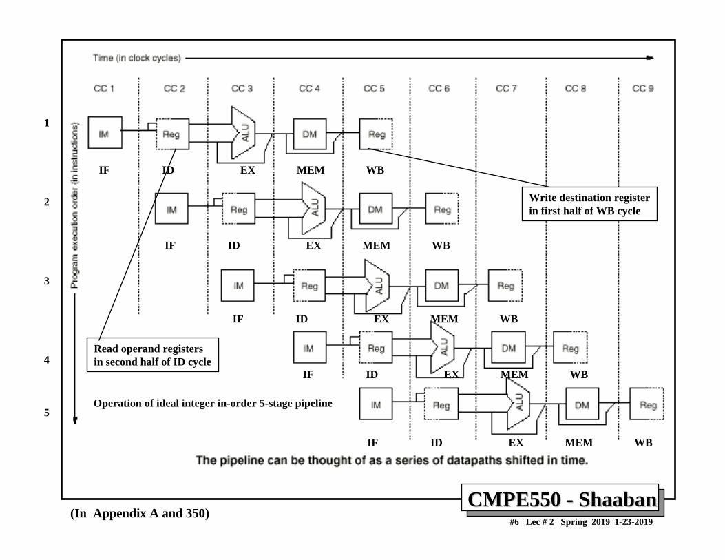
Read operand registersin second half of ID cycle
Write destination registerin first half of WB cycle
Operation of ideal integer in-order 5-stage pipeline
1
2
3
4
5
IF ID EX MEM WB
IF ID EX MEM WB
IF ID EX MEM WB
IF ID EX MEM WB
CMPE550 CMPE550 -- ShaabanShaaban#7 Lec # 2 Spring 2019 1-23-2019
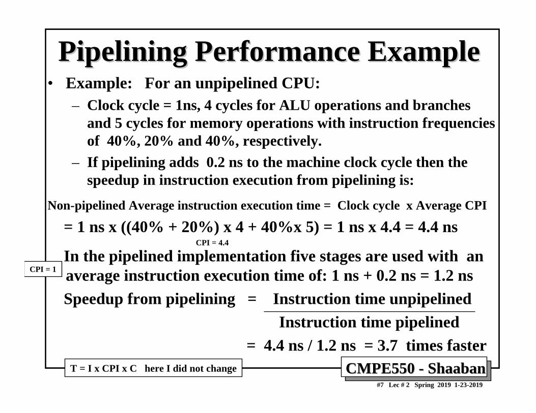
Pipelining Performance ExamplePipelining Performance Example• Example: For an unpipelined CPU:
– Clock cycle = 1ns, 4 cycles for ALU operations and branches and 5 cycles for memory operations with instruction frequencies of 40%, 20% and 40%, respectively.
– If pipelining adds 0.2 ns to the machine clock cycle then the speedup in instruction execution from pipelining is:
Non-pipelined Average instruction execution time = Clock cycle x Average CPI
= 1 ns x ((40% + 20%) x 4 + 40%x 5) = 1 ns x 4.4 = 4.4 ns
In the pipelined implementation five stages are used with an average instruction execution time of: 1 ns + 0.2 ns = 1.2 nsSpeedup from pipelining = Instruction time unpipelined
Instruction time pipelined= 4.4 ns / 1.2 ns = 3.7 times faster
CPI = 1
CPI = 4.4
T = I x CPI x C here I did not change
CMPE550 CMPE550 -- ShaabanShaaban#8 Lec # 2 Spring 2019 1-23-2019
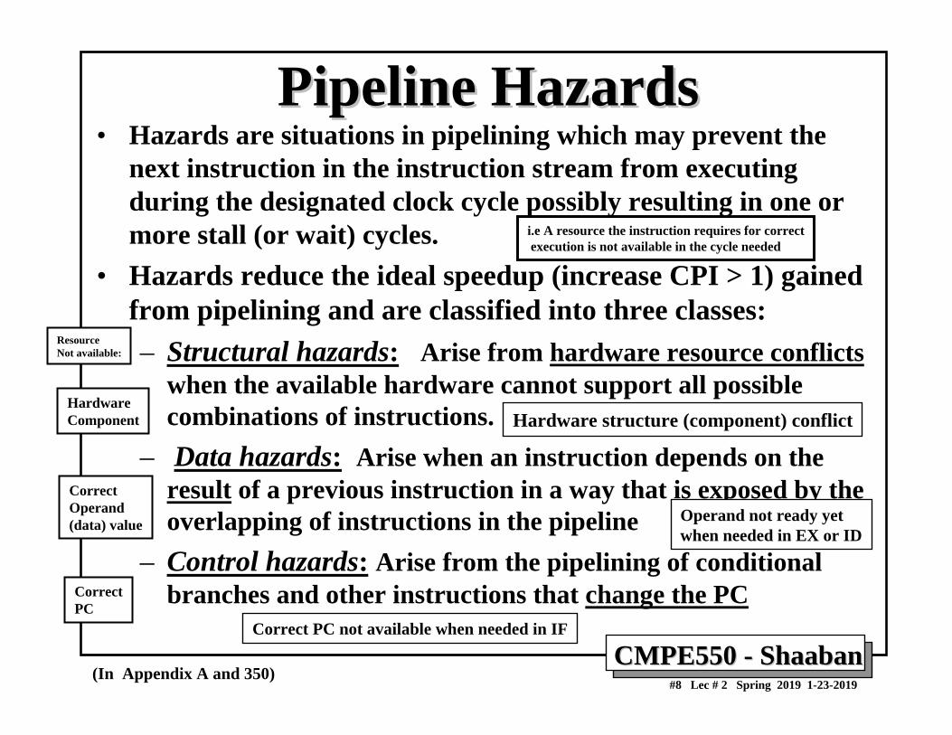
Pipeline HazardsPipeline Hazards• Hazards are situations in pipelining which may prevent the
next instruction in the instruction stream from executing during the designated clock cycle possibly resulting in one or more stall (or wait) cycles.
• Hazards reduce the ideal speedup (increase CPI > 1) gained from pipelining and are classified into three classes:– Structural hazards: Arise from hardware resource conflicts
when the available hardware cannot support all possible combinations of instructions.
– Data hazards: Arise when an instruction depends on the result of a previous instruction in a way that is exposed by the overlapping of instructions in the pipeline
– Control hazards: Arise from the pipelining of conditional branches and other instructions that change the PC
(In Appendix A and 350)
i.e A resource the instruction requires for correctexecution is not available in the cycle needed
Resource Not available:
HardwareComponent
CorrectOperand(data) value
CorrectPC
Hardware structure (component) conflict
Operand not ready yetwhen needed in EX or ID
Correct PC not available when needed in IF
CMPE550 CMPE550 -- ShaabanShaaban#9 Lec # 2 Spring 2019 1-23-2019
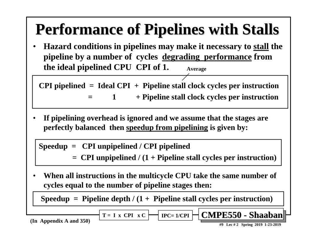
Performance of Pipelines with StallsPerformance of Pipelines with Stalls• Hazard conditions in pipelines may make it necessary to stall the
pipeline by a number of cycles degrading performance from the ideal pipelined CPU CPI of 1.
CPI pipelined = Ideal CPI + Pipeline stall clock cycles per instruction= 1 + Pipeline stall clock cycles per instruction
• If pipelining overhead is ignored and we assume that the stages are perfectly balanced then speedup from pipelining is given by:
Speedup = CPI unpipelined / CPI pipelined = CPI unpipelined / (1 + Pipeline stall cycles per instruction)
• When all instructions in the multicycle CPU take the same number of cycles equal to the number of pipeline stages then:
Speedup = Pipeline depth / (1 + Pipeline stall cycles per instruction)
(In Appendix A and 350)T = I x CPI x C IPC= 1/CPI
Average
CMPE550 CMPE550 -- ShaabanShaaban#10 Lec # 2 Spring 2019 1-23-2019
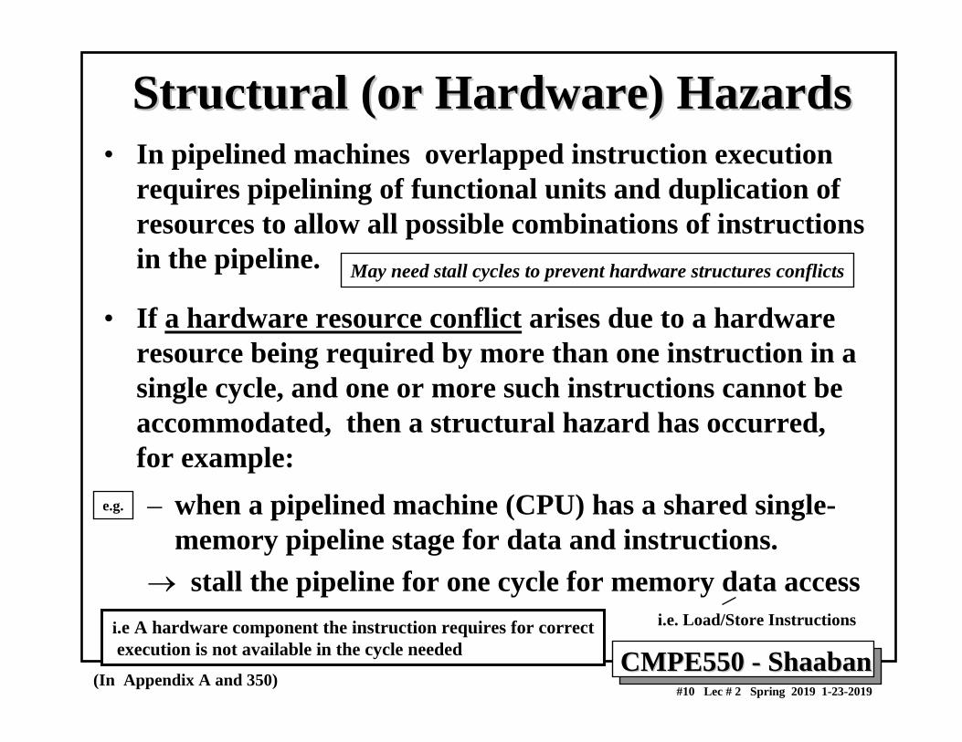
Structural (or Hardware) HazardsStructural (or Hardware) Hazards• In pipelined machines overlapped instruction execution
requires pipelining of functional units and duplication of resources to allow all possible combinations of instructions in the pipeline.
• If a hardware resource conflict arises due to a hardware resource being required by more than one instruction in a single cycle, and one or more such instructions cannot be accommodated, then a structural hazard has occurred, for example:– when a pipelined machine (CPU) has a shared single-
memory pipeline stage for data and instructions.→ stall the pipeline for one cycle for memory data access
(In Appendix A and 350)
i.e A hardware component the instruction requires for correctexecution is not available in the cycle needed
e.g.
May need stall cycles to prevent hardware structures conflicts
i.e. Load/Store Instructions
CMPE550 CMPE550 -- ShaabanShaaban#11 Lec # 2 Spring 2019 1-23-2019
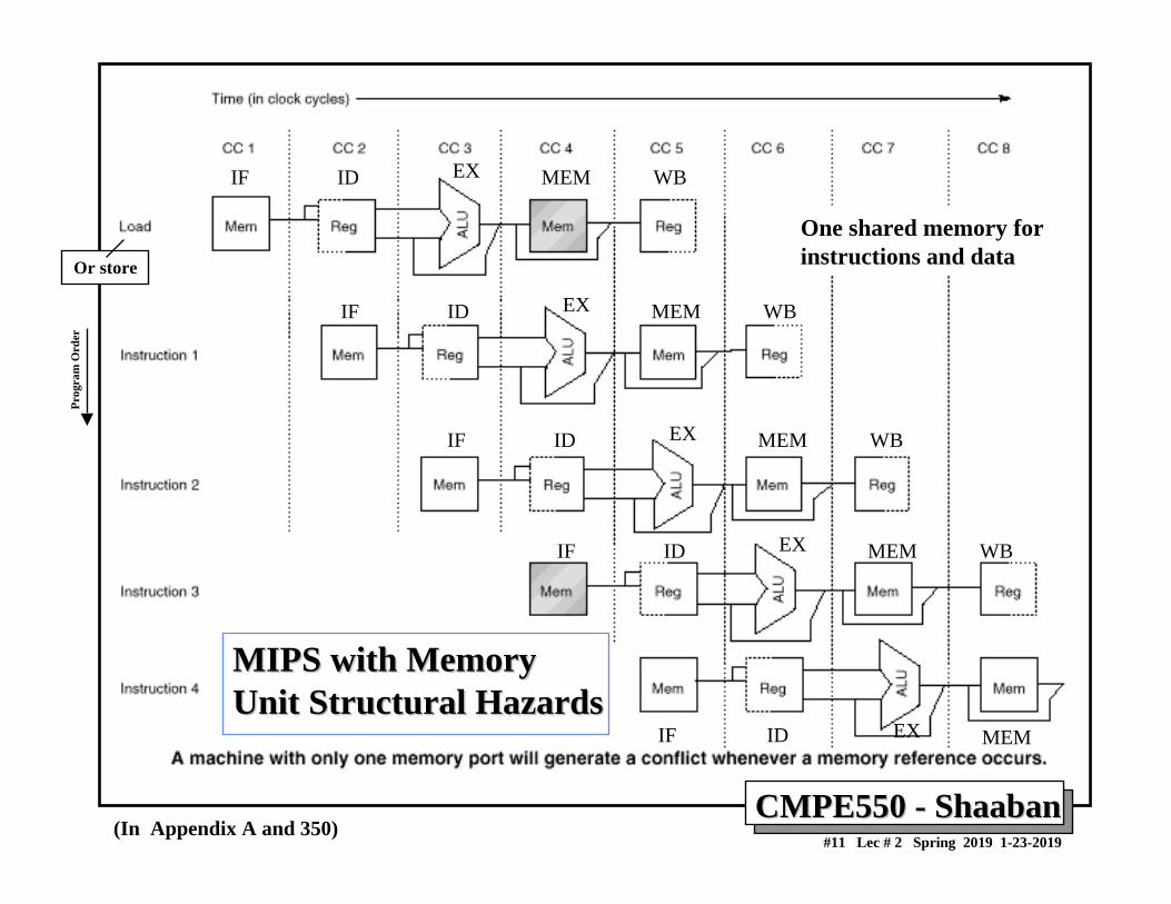
MIPS with MemoryMIPS with MemoryUnit Structural HazardsUnit Structural Hazards
(In Appendix A and 350)
One shared memory forinstructions and data
Prog
ram
Ord
er
Or store
IF ID EX MEM WB
IF ID EX MEM WB
IF ID EX MEM WB
IF ID EX MEM WB
IF ID EX MEM
CMPE550 CMPE550 -- ShaabanShaaban#12 Lec # 2 Spring 2019 1-23-2019
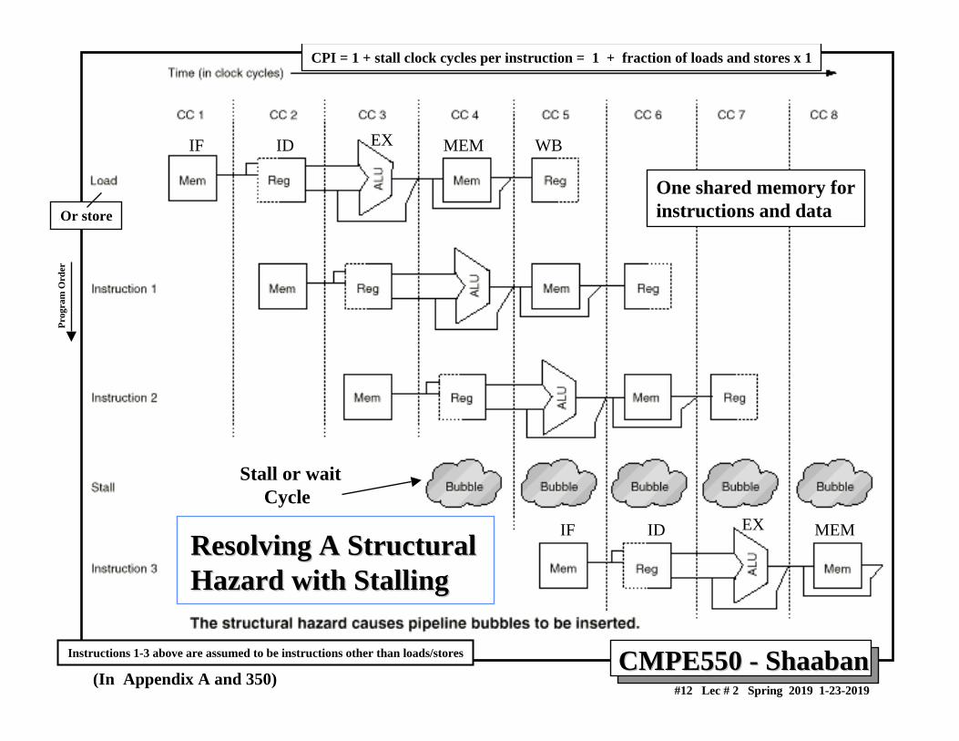
Resolving A StructuralResolving A StructuralHazard with StallingHazard with Stalling
(In Appendix A and 350)
One shared memory forinstructions and data
Stall or waitCycle
CPI = 1 + stall clock cycles per instruction = 1 + fraction of loads and stores x 1
Instructions 1-3 above are assumed to be instructions other than loads/stores
Prog
ram
Ord
er
Or store
IF ID EX MEM WB
IF ID EX MEM
CMPE550 CMPE550 -- ShaabanShaaban#13 Lec # 2 Spring 2019 1-23-2019
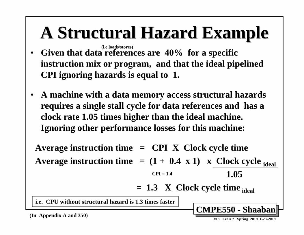
A Structural Hazard ExampleA Structural Hazard Example• Given that data references are 40% for a specific
instruction mix or program, and that the ideal pipelined CPI ignoring hazards is equal to 1.
• A machine with a data memory access structural hazards requires a single stall cycle for data references and has a clock rate 1.05 times higher than the ideal machine. Ignoring other performance losses for this machine:
Average instruction time = CPI X Clock cycle timeAverage instruction time = (1 + 0.4 x 1) x Clock cycle ideal
1.05= 1.3 X Clock cycle time ideal
CPI = 1.4
i.e. CPU without structural hazard is 1.3 times faster
(i.e loads/stores)
(In Appendix A and 350)
CMPE550 CMPE550 -- ShaabanShaaban#14 Lec # 2 Spring 2019 1-23-2019
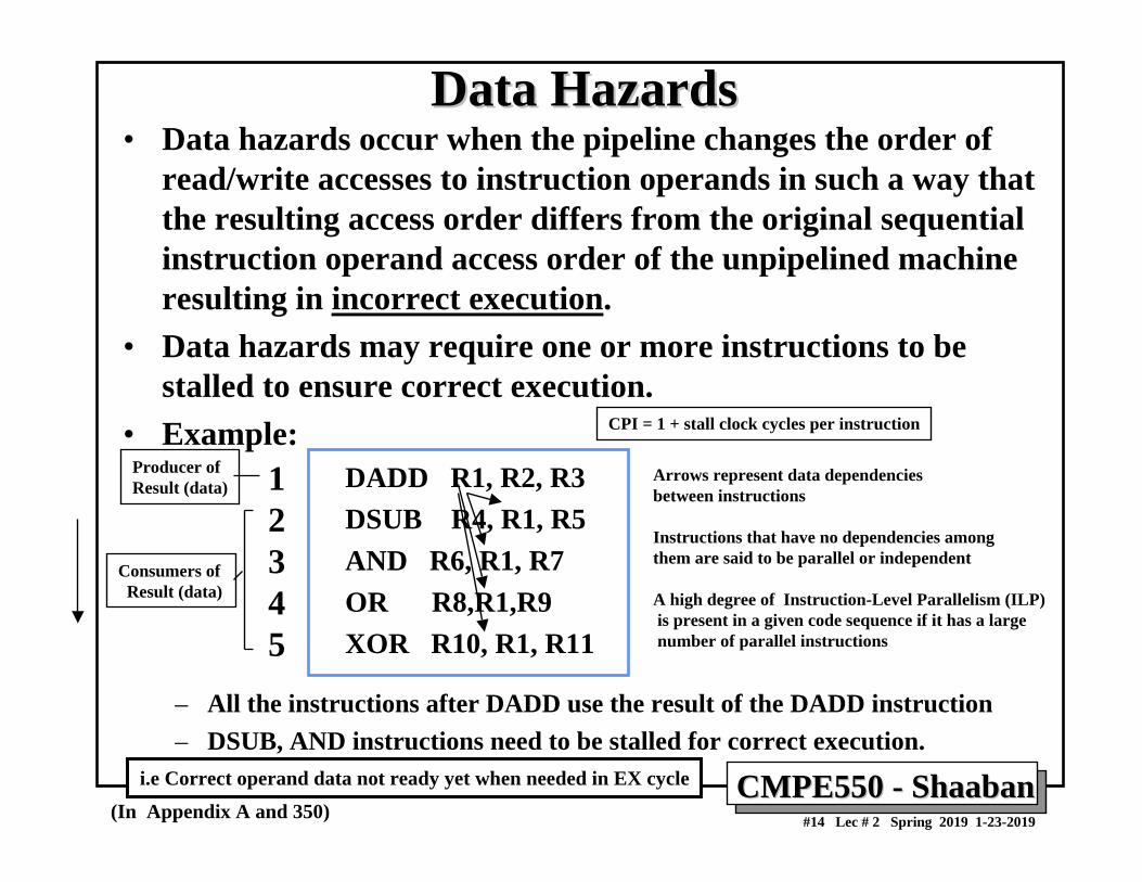
Data HazardsData Hazards• Data hazards occur when the pipeline changes the order of
read/write accesses to instruction operands in such a way that the resulting access order differs from the original sequential instruction operand access order of the unpipelined machine resulting in incorrect execution.
• Data hazards may require one or more instructions to be stalled to ensure correct execution.
• Example:DADD R1, R2, R3DSUB R4, R1, R5AND R6, R1, R7OR R8,R1,R9XOR R10, R1, R11
– All the instructions after DADD use the result of the DADD instruction– DSUB, AND instructions need to be stalled for correct execution.
(In Appendix A and 350)
12345
Arrows represent data dependenciesbetween instructions
Instructions that have no dependencies among them are said to be parallel or independent
A high degree of Instruction-Level Parallelism (ILP)is present in a given code sequence if it has a largenumber of parallel instructions
i.e Correct operand data not ready yet when needed in EX cycle
CPI = 1 + stall clock cycles per instruction
Producer of Result (data)
Consumers of Result (data)
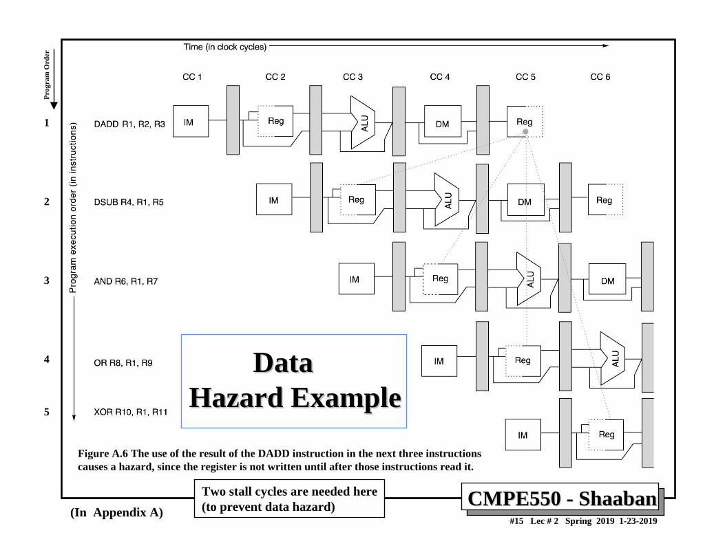
CMPE550 CMPE550 -- ShaabanShaaban#15 Lec # 2 Spring 2019 1-23-2019
Figure A.6 The use of the result of the DADD instruction in the next three instructionscauses a hazard, since the register is not written until after those instructions read it.
Data Data Hazard ExampleHazard Example
(In Appendix A)
1
2
3
4
5
Two stall cycles are needed here(to prevent data hazard)
Prog
ram
Ord
er
CMPE550 CMPE550 -- ShaabanShaaban#16 Lec # 2 Spring 2019 1-23-2019
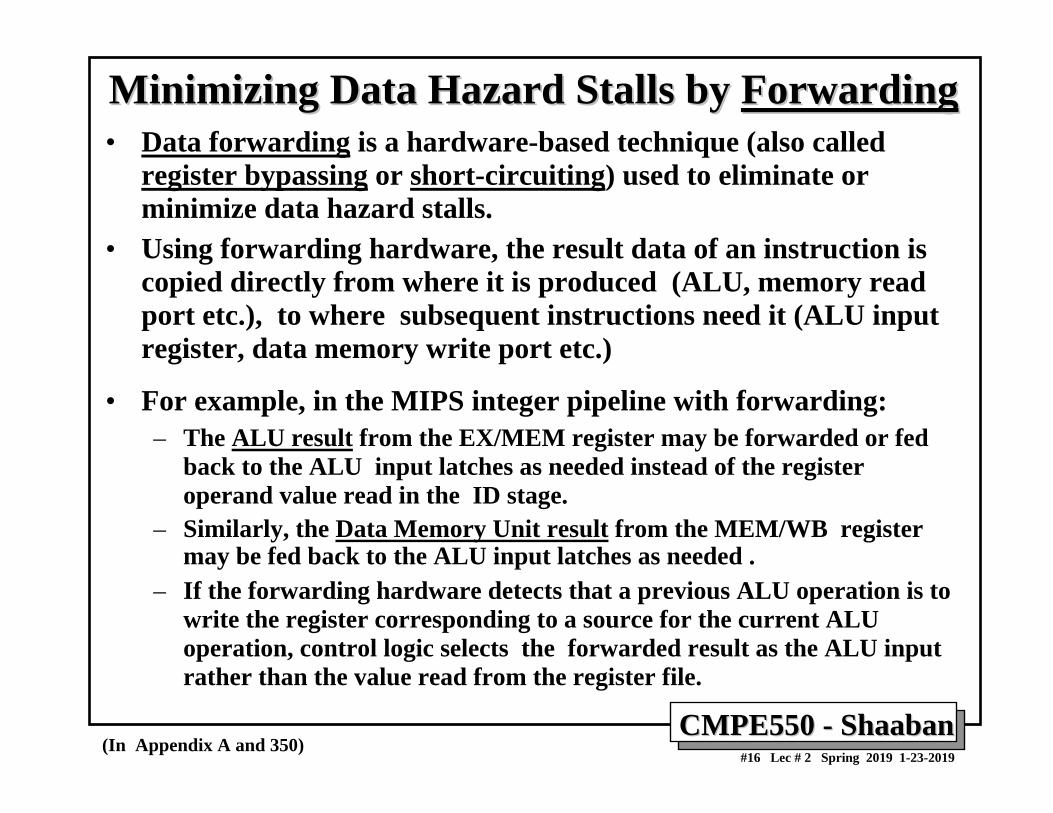
Minimizing Data Hazard Stalls by Minimizing Data Hazard Stalls by ForwardingForwarding• Data forwarding is a hardware-based technique (also called
register bypassing or short-circuiting) used to eliminate or minimize data hazard stalls.
• Using forwarding hardware, the result data of an instruction is copied directly from where it is produced (ALU, memory read port etc.), to where subsequent instructions need it (ALU input register, data memory write port etc.)
• For example, in the MIPS integer pipeline with forwarding:– The ALU result from the EX/MEM register may be forwarded or fed
back to the ALU input latches as needed instead of the registeroperand value read in the ID stage.
– Similarly, the Data Memory Unit result from the MEM/WB register may be fed back to the ALU input latches as needed .
– If the forwarding hardware detects that a previous ALU operation is to write the register corresponding to a source for the current ALUoperation, control logic selects the forwarded result as the ALU input rather than the value read from the register file.
(In Appendix A and 350)
CMPE550 CMPE550 -- ShaabanShaaban#17 Lec # 2 Spring 2019 1-23-2019
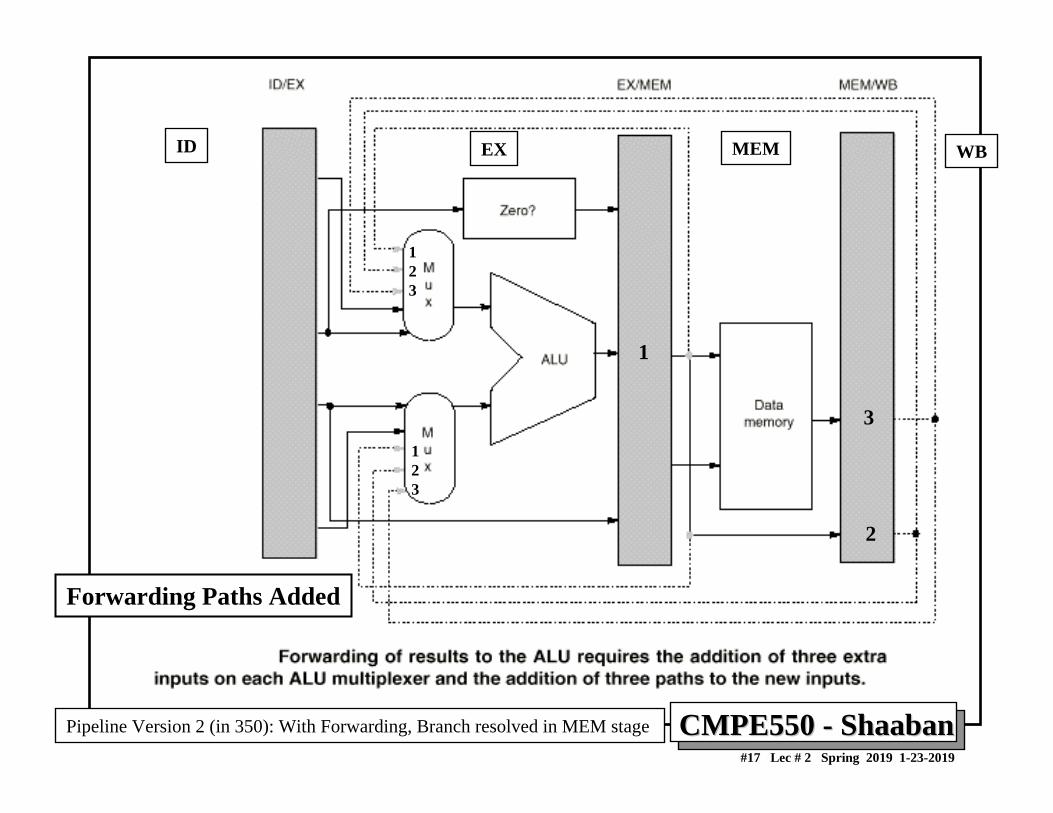
Forwarding Paths Added
EX MEM WBID
1
3
2
123
123
Pipeline Version 2 (in 350): With Forwarding, Branch resolved in MEM stage
CMPE550 CMPE550 -- ShaabanShaaban#18 Lec # 2 Spring 2019 1-23-2019
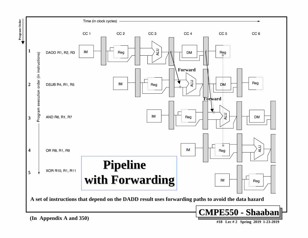
PipelinePipelinewith Forwardingwith Forwarding
A set of instructions that depend on the DADD result uses forwarding paths to avoid the data hazard
(In Appendix A and 350)
Forward
Forward
1
2
3
4
5
Prog
ram
Ord
er
CMPE550 CMPE550 -- ShaabanShaaban#19 Lec # 2 Spring 2019 1-23-2019
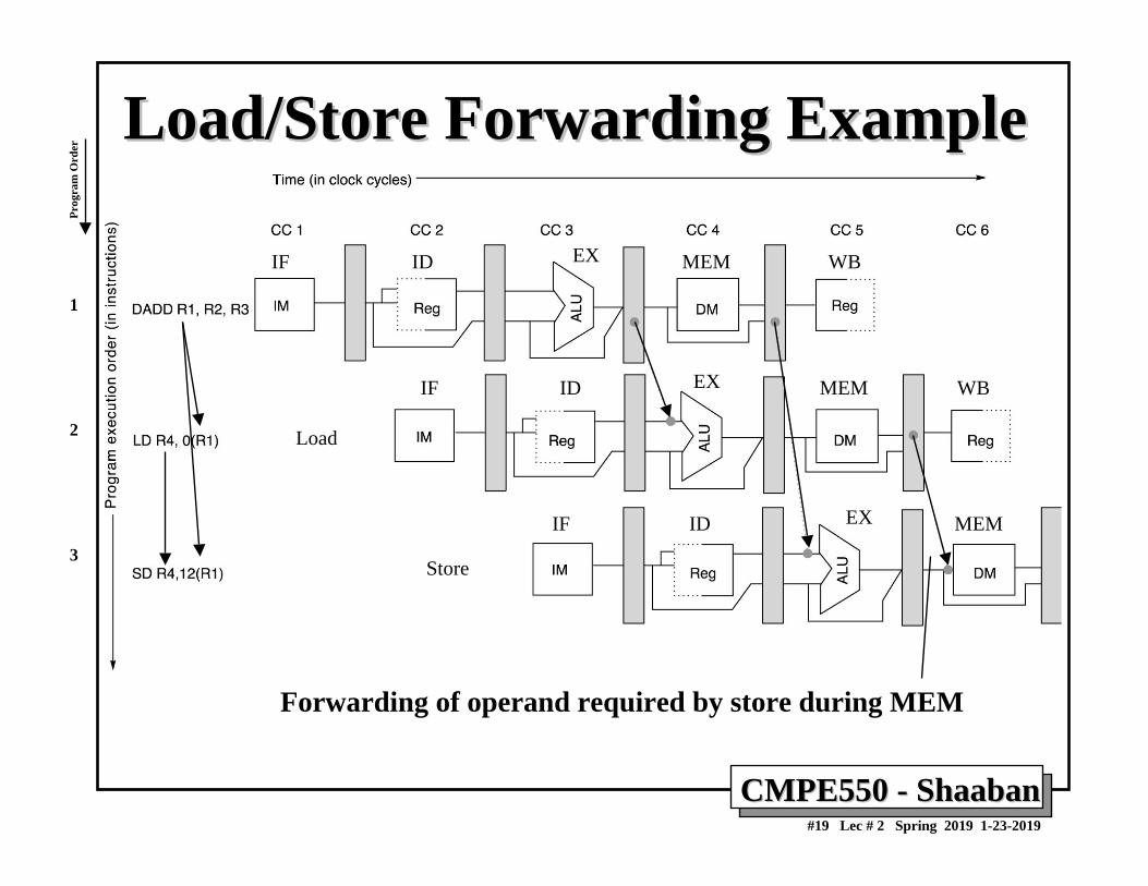
Load/Store Forwarding ExampleLoad/Store Forwarding Example
Forwarding of operand required by store during MEM
Load
Store
1
2
3
Prog
ram
Ord
er
IF ID EX MEM WB
IF ID EX MEM WB
IF ID EX MEM
CMPE550 CMPE550 -- ShaabanShaaban#20 Lec # 2 Spring 2019 1-23-2019
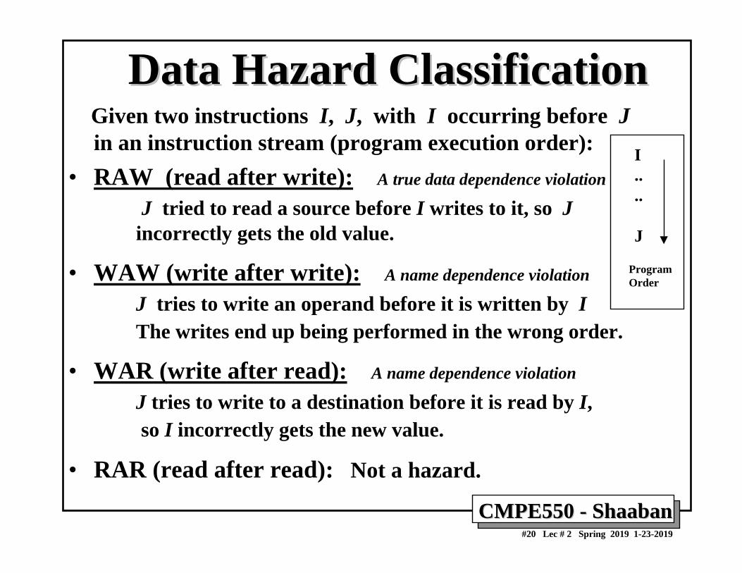
Data Hazard ClassificationData Hazard ClassificationGiven two instructions I, J, with I occurring before J in an instruction stream (program execution order):
• RAW (read after write): A true data dependence violation
J tried to read a source before I writes to it, so Jincorrectly gets the old value.
• WAW (write after write): A name dependence violation
J tries to write an operand before it is written by IThe writes end up being performed in the wrong order.
• WAR (write after read): A name dependence violation
J tries to write to a destination before it is read by I,so I incorrectly gets the new value.
• RAR (read after read): Not a hazard.
I....
J
ProgramOrder
CMPE550 CMPE550 -- ShaabanShaaban#21 Lec # 2 Spring 2019 1-23-2019
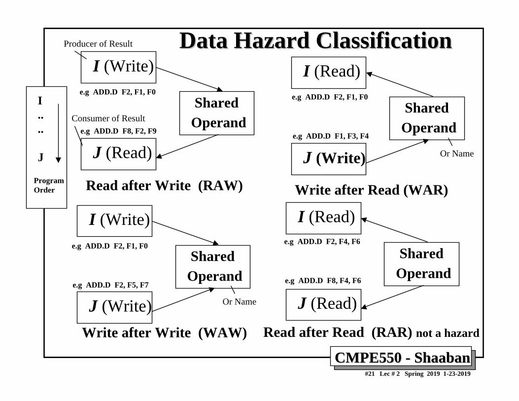
Data Hazard ClassificationData Hazard ClassificationI (Write)
SharedOperand
J (Read)
Read after Write (RAW)
I (Read)
SharedOperand
J (Write)
Write after Read (WAR)
I (Write)
SharedOperand
J (Write)Write after Write (WAW)
I (Read)
SharedOperand
J (Read)
Read after Read (RAR) not a hazard
I....
J
ProgramOrder
e.g ADD.D F2, F1, F0
e.g ADD.D F8, F2, F9
e.g ADD.D F2, F1, F0
e.g ADD.D F1, F3, F4
e.g ADD.D F2, F1, F0
e.g ADD.D F2, F5, F7
e.g ADD.D F2, F4, F6
e.g ADD.D F8, F4, F6
Or Name
Or Name
Producer of Result
Consumer of Result
CMPE550 CMPE550 -- ShaabanShaaban#22 Lec # 2 Spring 2019 1-23-2019
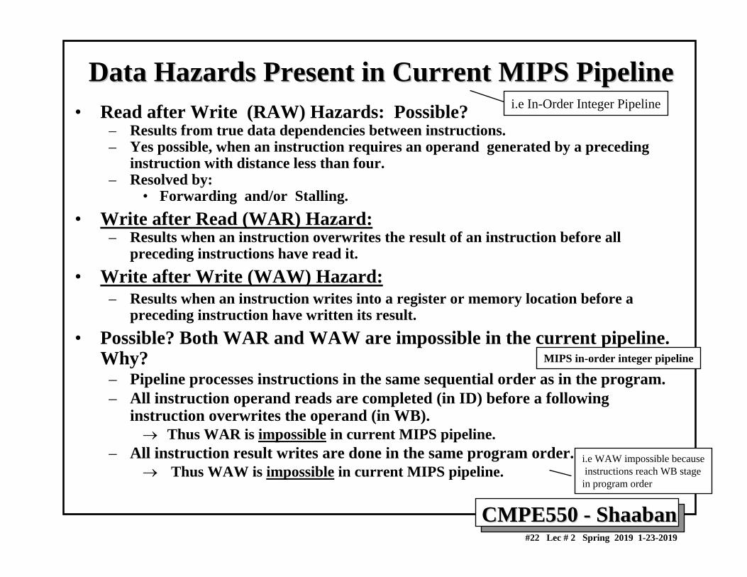
Data Hazards Present in Current MIPS PipelineData Hazards Present in Current MIPS Pipeline• Read after Write (RAW) Hazards: Possible?
– Results from true data dependencies between instructions.– Yes possible, when an instruction requires an operand generated by a preceding
instruction with distance less than four.– Resolved by:
• Forwarding and/or Stalling.• Write after Read (WAR) Hazard:
– Results when an instruction overwrites the result of an instruction before all preceding instructions have read it.
• Write after Write (WAW) Hazard:– Results when an instruction writes into a register or memory location before a
preceding instruction have written its result.• Possible? Both WAR and WAW are impossible in the current pipeline.
Why?– Pipeline processes instructions in the same sequential order as in the program.– All instruction operand reads are completed (in ID) before a following
instruction overwrites the operand (in WB).→ Thus WAR is impossible in current MIPS pipeline.
– All instruction result writes are done in the same program order.→ Thus WAW is impossible in current MIPS pipeline.
MIPS in-order integer pipeline
i.e In-Order Integer Pipeline
i.e WAW impossible becauseinstructions reach WB stage
in program order
CMPE550 CMPE550 -- ShaabanShaaban#23 Lec # 2 Spring 2019 1-23-2019
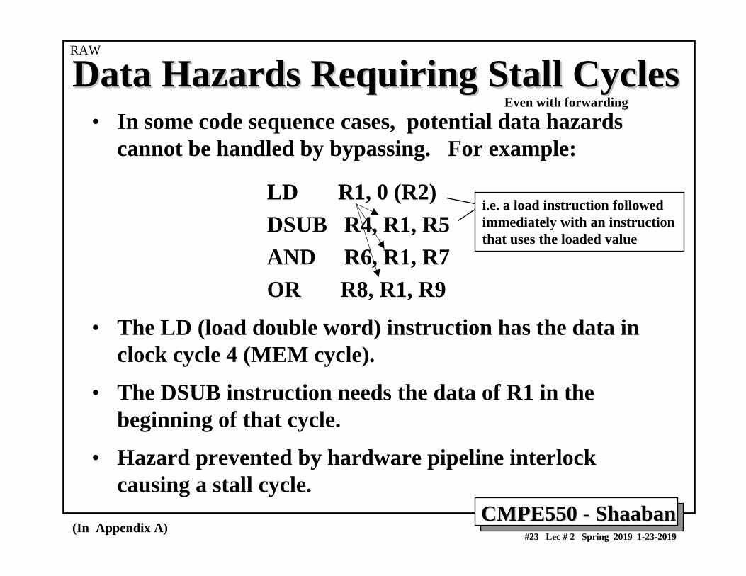
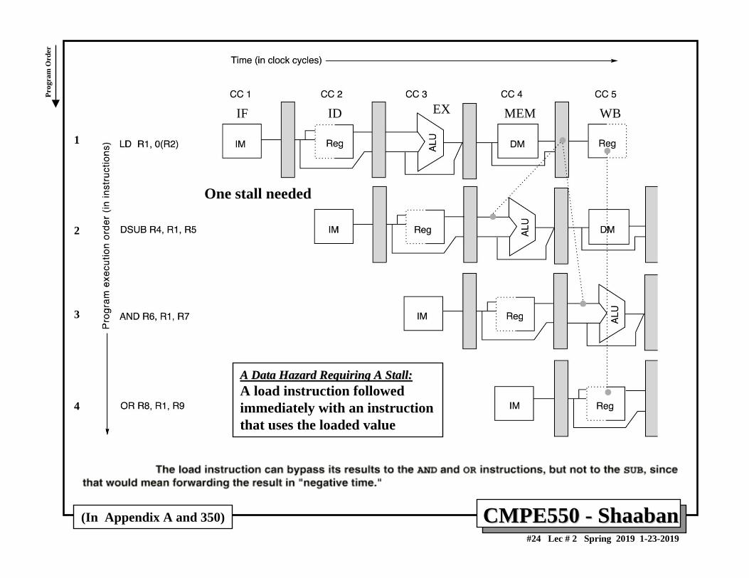
Data Hazards Requiring Stall CyclesData Hazards Requiring Stall Cycles• In some code sequence cases, potential data hazards
cannot be handled by bypassing. For example:
LD R1, 0 (R2)DSUB R4, R1, R5AND R6, R1, R7OR R8, R1, R9
• The LD (load double word) instruction has the data in clock cycle 4 (MEM cycle).
• The DSUB instruction needs the data of R1 in the beginning of that cycle.
• Hazard prevented by hardware pipeline interlock causing a stall cycle.
(In Appendix A)
i.e. a load instruction followed immediately with an instruction that uses the loaded value
RAW
Even with forwarding
CMPE550 CMPE550 -- ShaabanShaaban#24 Lec # 2 Spring 2019 1-23-2019
(In Appendix A and 350)
One stall needed
A Data Hazard Requiring A Stall:A Data Hazard Requiring A Stall:A load instruction followed immediately with an instruction that uses the loaded value
1
2
3
4
Prog
ram
Ord
er
IF ID EX MEM WB
CMPE550 CMPE550 -- ShaabanShaaban#25 Lec # 2 Spring 2019 1-23-2019
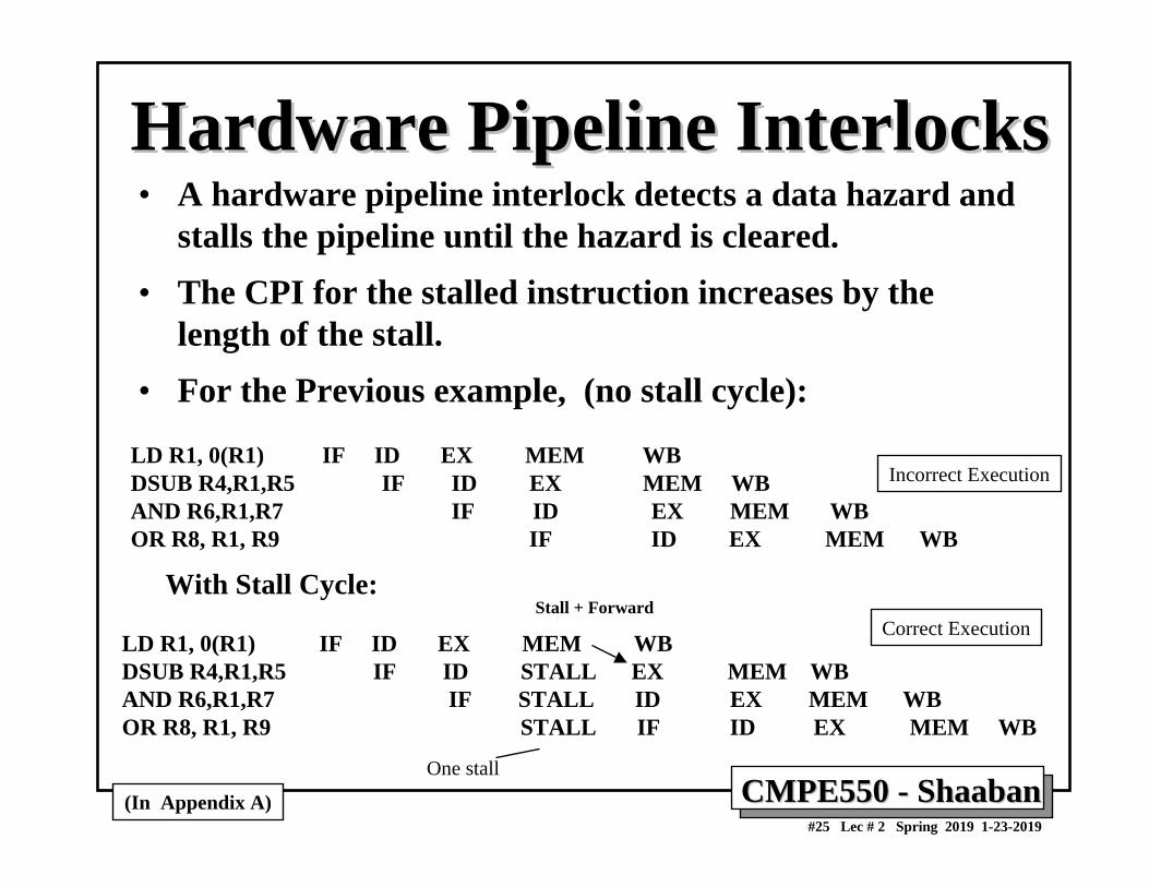
Hardware Pipeline InterlocksHardware Pipeline Interlocks• A hardware pipeline interlock detects a data hazard and
stalls the pipeline until the hazard is cleared.• The CPI for the stalled instruction increases by the
length of the stall.• For the Previous example, (no stall cycle):
LD R1, 0(R1) IF ID EX MEM WBDSUB R4,R1,R5 IF ID EX MEM WBAND R6,R1,R7 IF ID EX MEM WBOR R8, R1, R9 IF ID EX MEM WB
With Stall Cycle:
LD R1, 0(R1) IF ID EX MEM WBDSUB R4,R1,R5 IF ID STALL EX MEM WBAND R6,R1,R7 IF STALL ID EX MEM WBOR R8, R1, R9 STALL IF ID EX MEM WB
(In Appendix A)
Stall + Forward
Incorrect Execution
Correct Execution
One stall
CMPE550 CMPE550 -- ShaabanShaaban#26 Lec # 2 Spring 2019 1-23-2019
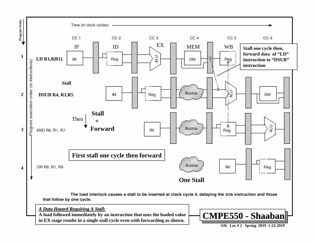
DSUB R4, R1,R5
LD R1,0(R1)
Stall
One Stall
Stall+
Forward
A Data Hazard Requiring A Stall:A Data Hazard Requiring A Stall:A load followed immediately by an instruction that uses the loaded valuein EX stage results in a single stall cycle even with forwarding as shown.
Stall one cycle then, forward data of “LD”instruction to “DSUB”instruction
First stall one cycle then forward
Then
1
2
3
4
Prog
ram
Ord
er
IF ID EX MEM WB
CMPE550 CMPE550 -- ShaabanShaaban#27 Lec # 2 Spring 2019 1-23-2019
Stall + forward
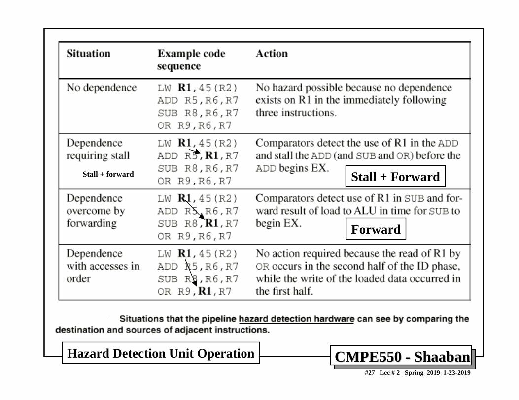
Hazard Detection Unit Operation
Stall + Forward
Forward
CMPE550 CMPE550 -- ShaabanShaaban#28 Lec # 2 Spring 2019 1-23-2019
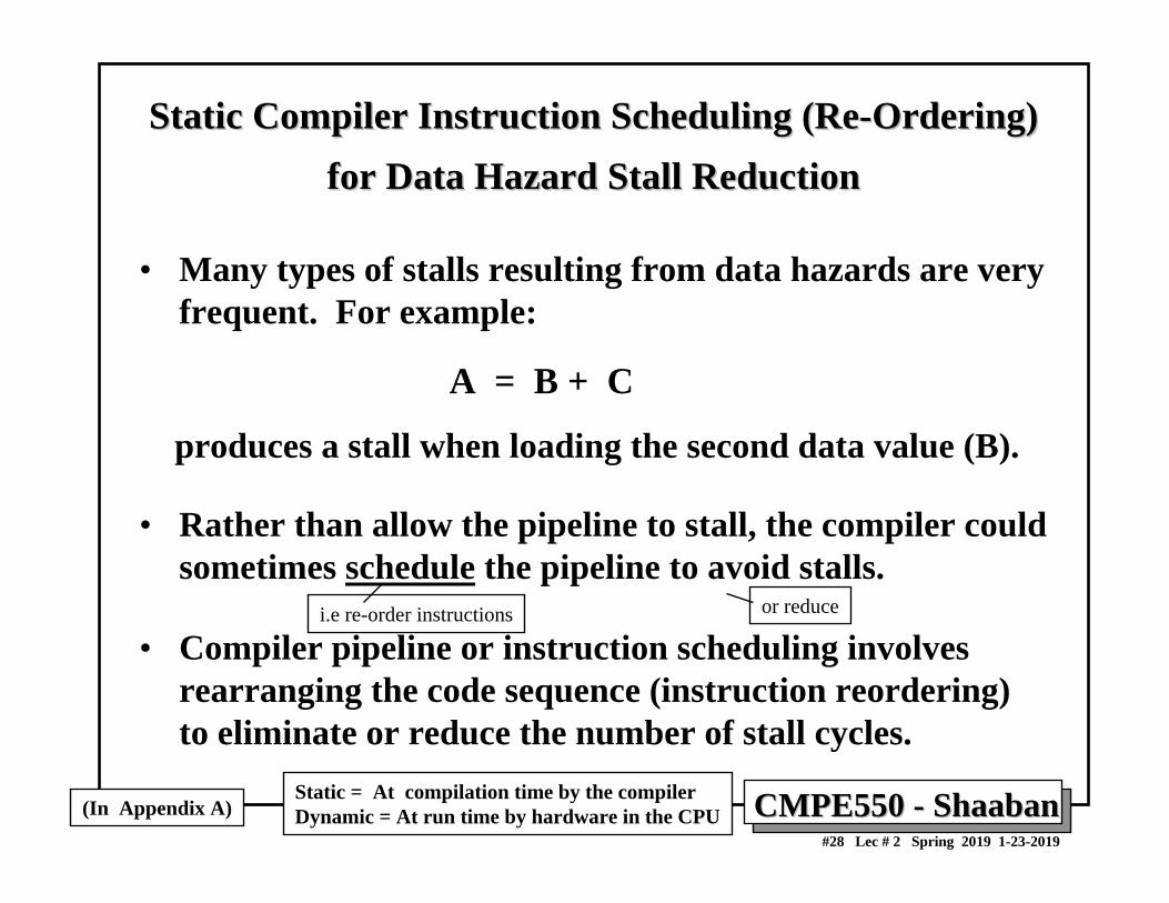
Static Compiler Instruction Scheduling (ReStatic Compiler Instruction Scheduling (Re--Ordering) Ordering) for Data Hazard Stall Reductionfor Data Hazard Stall Reduction
• Many types of stalls resulting from data hazards are very frequent. For example:
A = B + C
produces a stall when loading the second data value (B).
• Rather than allow the pipeline to stall, the compiler could sometimes schedule the pipeline to avoid stalls.
• Compiler pipeline or instruction scheduling involves rearranging the code sequence (instruction reordering) to eliminate or reduce the number of stall cycles.
(In Appendix A)Static = At compilation time by the compilerDynamic = At run time by hardware in the CPU
or reducei.e re-order instructions
CMPE550 CMPE550 -- ShaabanShaaban#29 Lec # 2 Spring 2019 1-23-2019
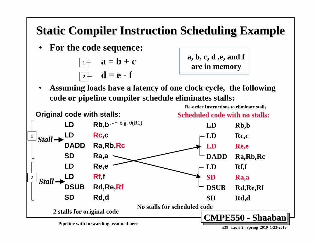
Static Compiler Instruction Scheduling ExampleStatic Compiler Instruction Scheduling Example• For the code sequence:
a = b + cd = e - f
• Assuming loads have a latency of one clock cycle, the followingcode or pipeline compiler schedule eliminates stalls:
a, b, c, d ,e, and fare in memory
Scheduled code with no stalls:LD Rb,bLD Rc,cLD Re,e DADD Ra,Rb,RcLD Rf,fSD Ra,a DSUB Rd,Re,RfSD Rd,d
Original code with stalls:LD Rb,bLD Rc,cDADD Ra,Rb,RcSD Ra,a LD Re,e LD Rf,fDSUB Rd,Re,RfSD Rd,d
Stall
Stall
2 stalls for original codeNo stalls for scheduled code
Re-order Instructions to eliminate stalls
Pipeline with forwarding assumed here
e.g. 0(R1)
1
2
1
2
CMPE550 CMPE550 -- ShaabanShaaban#30 Lec # 2 Spring 2019 1-23-2019
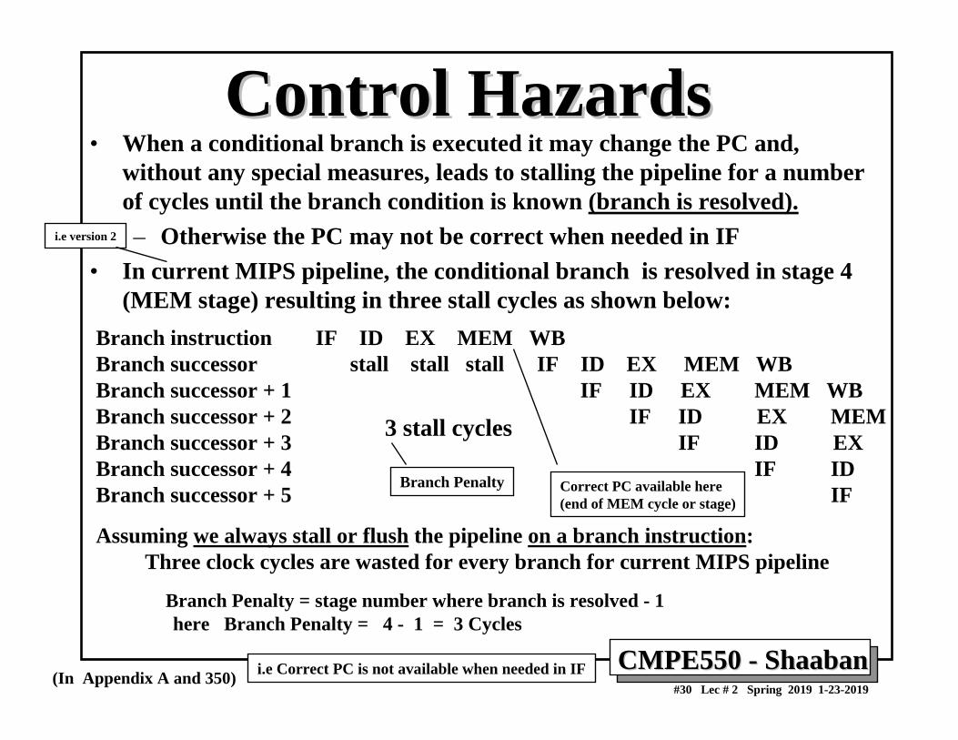
Control HazardsControl Hazards• When a conditional branch is executed it may change the PC and,
without any special measures, leads to stalling the pipeline for a number of cycles until the branch condition is known (branch is resolved).– Otherwise the PC may not be correct when needed in IF
• In current MIPS pipeline, the conditional branch is resolved in stage 4 (MEM stage) resulting in three stall cycles as shown below:
Branch instruction IF ID EX MEM WBBranch successor stall stall stall IF ID EX MEM WBBranch successor + 1 IF ID EX MEM WB Branch successor + 2 IF ID EX MEMBranch successor + 3 IF ID EXBranch successor + 4 IF IDBranch successor + 5 IF
Assuming we always stall or flush the pipeline on a branch instruction: Three clock cycles are wasted for every branch for current MIPS pipeline
Branch Penalty = stage number where branch is resolved - 1 here Branch Penalty = 4 - 1 = 3 Cycles
3 stall cycles
(In Appendix A and 350)
Branch Penalty Correct PC available here(end of MEM cycle or stage)
i.e Correct PC is not available when needed in IF
i.e version 2
CMPE550 CMPE550 -- ShaabanShaaban#31 Lec # 2 Spring 2019 1-23-2019
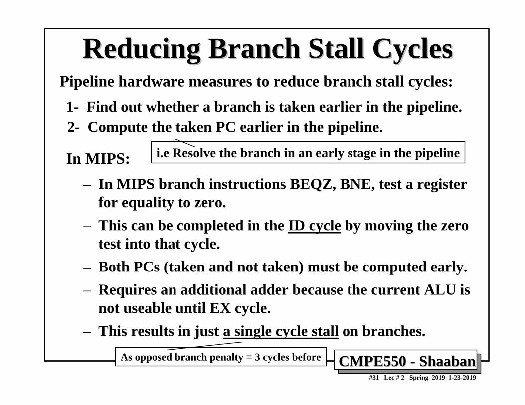
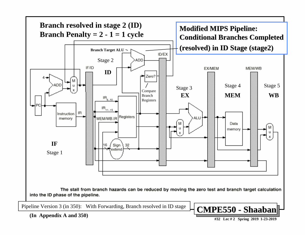
Reducing Branch Stall CyclesReducing Branch Stall CyclesPipeline hardware measures to reduce branch stall cycles:1- Find out whether a branch is taken earlier in the pipeline. 2- Compute the taken PC earlier in the pipeline.
In MIPS:– In MIPS branch instructions BEQZ, BNE, test a register
for equality to zero.– This can be completed in the ID cycle by moving the zero
test into that cycle.– Both PCs (taken and not taken) must be computed early.– Requires an additional adder because the current ALU is
not useable until EX cycle.– This results in just a single cycle stall on branches.
i.e Resolve the branch in an early stage in the pipeline
As opposed branch penalty = 3 cycles before
CMPE550 CMPE550 -- ShaabanShaaban#32 Lec # 2 Spring 2019 1-23-2019
Modified MIPS Pipeline:Modified MIPS Pipeline:Conditional Branches Completed Conditional Branches Completed (resolved) in ID Stage (stage2)(resolved) in ID Stage (stage2)
(In Appendix A and 350)
Branch resolved in stage 2 (ID)Branch Penalty = 2 - 1 = 1 cycle
IF
ID
EX MEM WB
Pipeline Version 3 (in 350): With Forwarding, Branch resolved in ID stage
Stage 1
Stage 2
Stage 3 Stage 4 Stage 5
Branch Target ALU
CompareBranchRegisters
CMPE550 CMPE550 -- ShaabanShaaban#33 Lec # 2 Spring 2019 1-23-2019
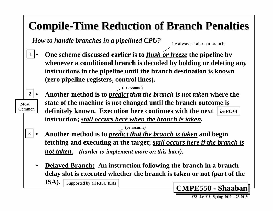
CompileCompile--Time Reduction of Branch PenaltiesTime Reduction of Branch Penalties
• One scheme discussed earlier is to flush or freeze the pipeline by whenever a conditional branch is decoded by holding or deleting any instructions in the pipeline until the branch destination is known (zero pipeline registers, control lines).
• Another method is to predict that the branch is not taken where the state of the machine is not changed until the branch outcome is definitely known. Execution here continues with the next instruction; stall occurs here when the branch is taken.
• Another method is to predict that the branch is taken and begin fetching and executing at the target; stall occurs here if the branch is not taken. (harder to implement more on this later).
• Delayed Branch: An instruction following the branch in a branch delay slot is executed whether the branch is taken or not (part of the ISA).
How to handle branches in a pipelined CPU?
MostCommon
1
2
3
(or assume)
i.e always stall on a branch
Supported by all RISC ISAs
i.e PC+4
(or assume)
CMPE550 CMPE550 -- ShaabanShaaban#34 Lec # 2 Spring 2019 1-23-2019
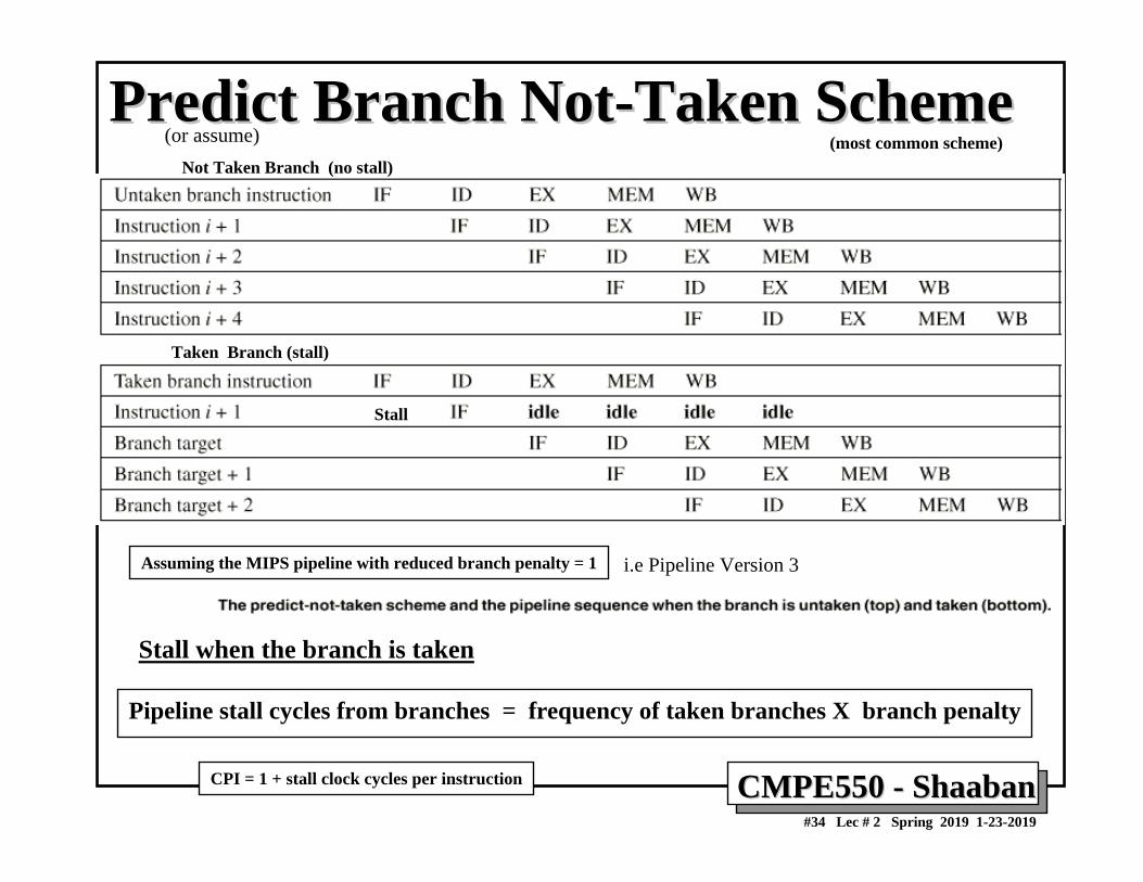
Predict Branch NotPredict Branch Not--Taken SchemeTaken Scheme
Pipeline stall cycles from branches = frequency of taken branches X branch penalty
Stall
Not Taken Branch (no stall)
Taken Branch (stall)
Stall when the branch is taken
(most common scheme)
Assuming the MIPS pipeline with reduced branch penalty = 1
CPI = 1 + stall clock cycles per instruction
i.e Pipeline Version 3
(or assume)
CMPE550 CMPE550 -- ShaabanShaaban#35 Lec # 2 Spring 2019 1-23-2019
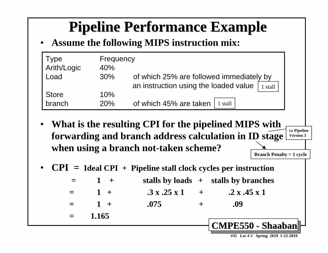
Pipeline Performance ExamplePipeline Performance Example• Assume the following MIPS instruction mix:
• What is the resulting CPI for the pipelined MIPS with forwarding and branch address calculation in ID stage when using a branch not-taken scheme?
• CPI = Ideal CPI + Pipeline stall clock cycles per instruction= 1 + stalls by loads + stalls by branches= 1 + .3 x .25 x 1 + .2 x .45 x 1= 1 + .075 + .09 = 1.165
Type FrequencyArith/Logic 40%Load 30% of which 25% are followed immediately by
an instruction using the loaded value Store 10%branch 20% of which 45% are taken
Branch Penalty = 1 cycle
i.e PipelineVersion 3
1 stall
1 stall
CMPE550 CMPE550 -- ShaabanShaaban#36 Lec # 2 Spring 2019 1-23-2019
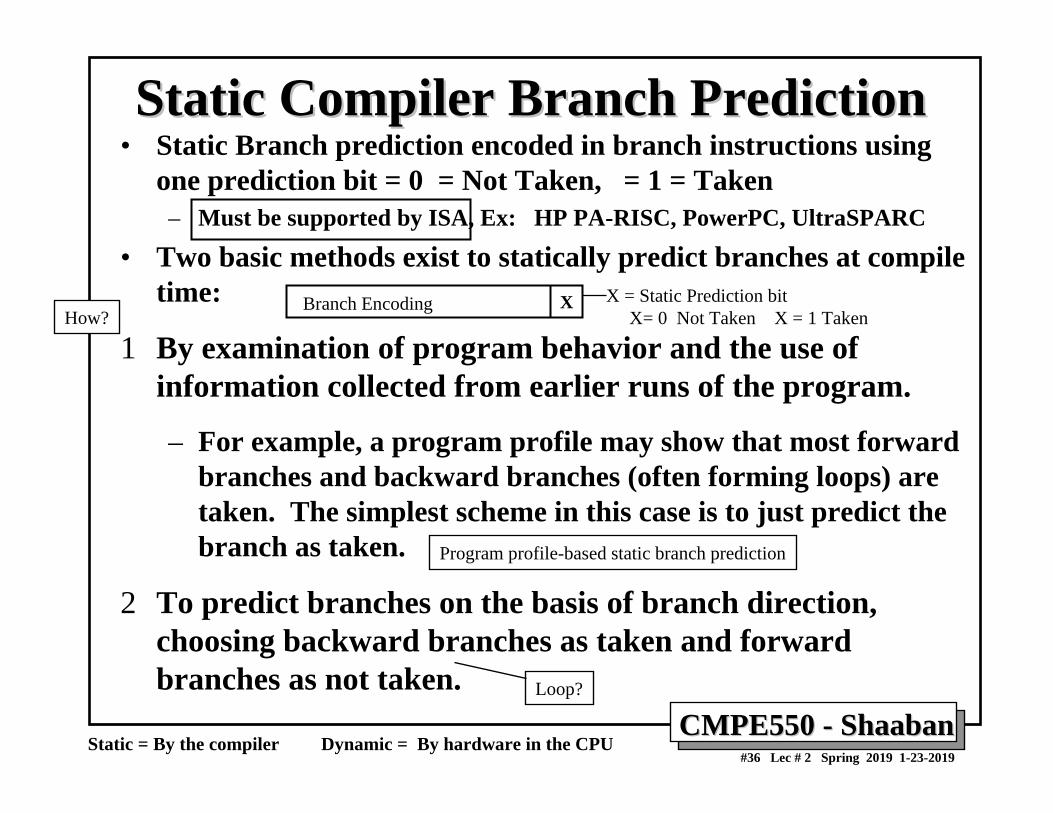
Static Compiler Branch PredictionStatic Compiler Branch Prediction• Static Branch prediction encoded in branch instructions using
one prediction bit = 0 = Not Taken, = 1 = Taken– Must be supported by ISA, Ex: HP PA-RISC, PowerPC, UltraSPARC
• Two basic methods exist to statically predict branches at compile time:
1 By examination of program behavior and the use of information collected from earlier runs of the program.
– For example, a program profile may show that most forward branches and backward branches (often forming loops) are taken. The simplest scheme in this case is to just predict the branch as taken.
2 To predict branches on the basis of branch direction, choosing backward branches as taken and forward branches as not taken.
Static = By the compiler Dynamic = By hardware in the CPU
XBranch Encoding X = Static Prediction bit X= 0 Not Taken X = 1 Taken
Program profile-based static branch prediction
How?
Loop?
CMPE550 CMPE550 -- ShaabanShaaban#37 Lec # 2 Spring 2019 1-23-2019
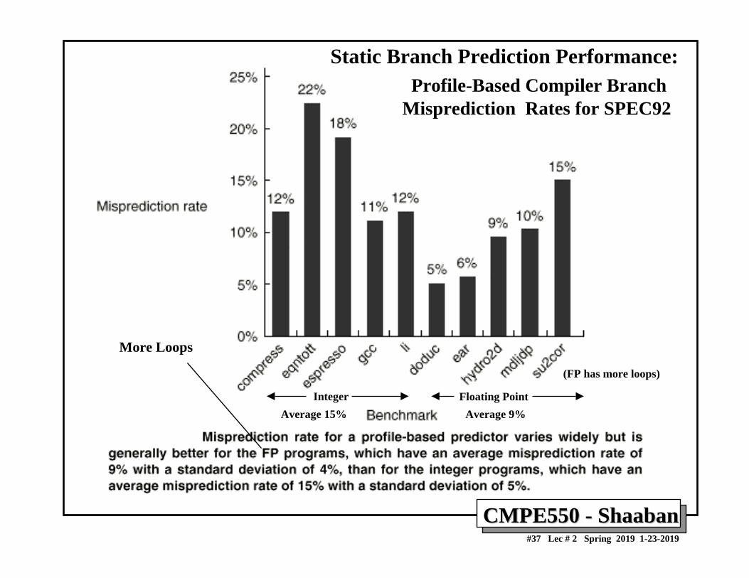
Profile-Based Compiler Branch Misprediction Rates for SPEC92
Floating PointInteger
More Loops
Static Branch Prediction Performance:
Average 9%Average 15%
(FP has more loops)
CMPE550 CMPE550 -- ShaabanShaaban#38 Lec # 2 Spring 2019 1-23-2019
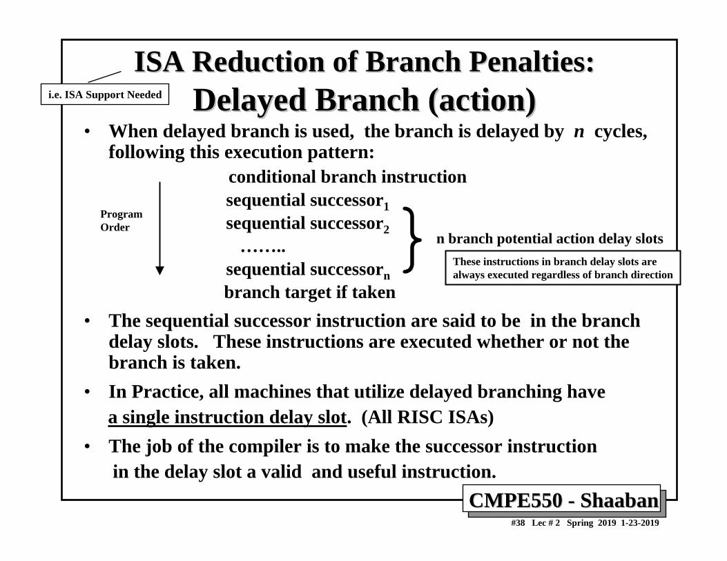
ISA Reduction of Branch Penalties:ISA Reduction of Branch Penalties:Delayed Branch (action)Delayed Branch (action)
• When delayed branch is used, the branch is delayed by n cycles, following this execution pattern:
conditional branch instructionsequential successor1sequential successor2
……..sequential successornbranch target if taken
• The sequential successor instruction are said to be in the branch delay slots. These instructions are executed whether or not the branch is taken.
• In Practice, all machines that utilize delayed branching have a single instruction delay slot. (All RISC ISAs)
• The job of the compiler is to make the successor instruction in the delay slot a valid and useful instruction.
n branch potential action delay slots}ProgramOrder
These instructions in branch delay slots are always executed regardless of branch direction
i.e. ISA Support Needed
CMPE550 CMPE550 -- ShaabanShaaban#39 Lec # 2 Spring 2019 1-23-2019
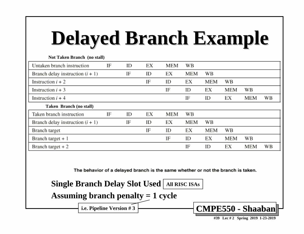
Delayed Branch ExampleDelayed Branch Example
Single Branch Delay Slot UsedAssuming branch penalty = 1 cycle
Not Taken Branch (no stall)
Taken Branch (no stall)
All RISC ISAs
i.e. Pipeline Version # 3
CMPE550 CMPE550 -- ShaabanShaaban#40 Lec # 2 Spring 2019 1-23-2019
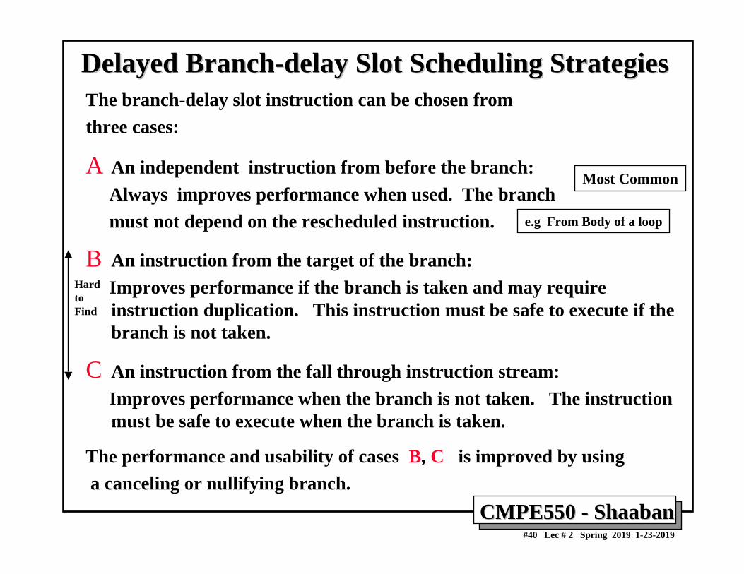
Delayed BranchDelayed Branch--delay Slot Scheduling Strategiesdelay Slot Scheduling StrategiesThe branch-delay slot instruction can be chosen from three cases:
A An independent instruction from before the branch:Always improves performance when used. The branch must not depend on the rescheduled instruction.
B An instruction from the target of the branch:Improves performance if the branch is taken and may requireinstruction duplication. This instruction must be safe to execute if the branch is not taken.
C An instruction from the fall through instruction stream:Improves performance when the branch is not taken. The instruction must be safe to execute when the branch is taken.
The performance and usability of cases B, C is improved by using a canceling or nullifying branch.
Most Common
HardtoFind
e.g From Body of a loop
CMPE550 CMPE550 -- ShaabanShaaban#41 Lec # 2 Spring 2019 1-23-2019
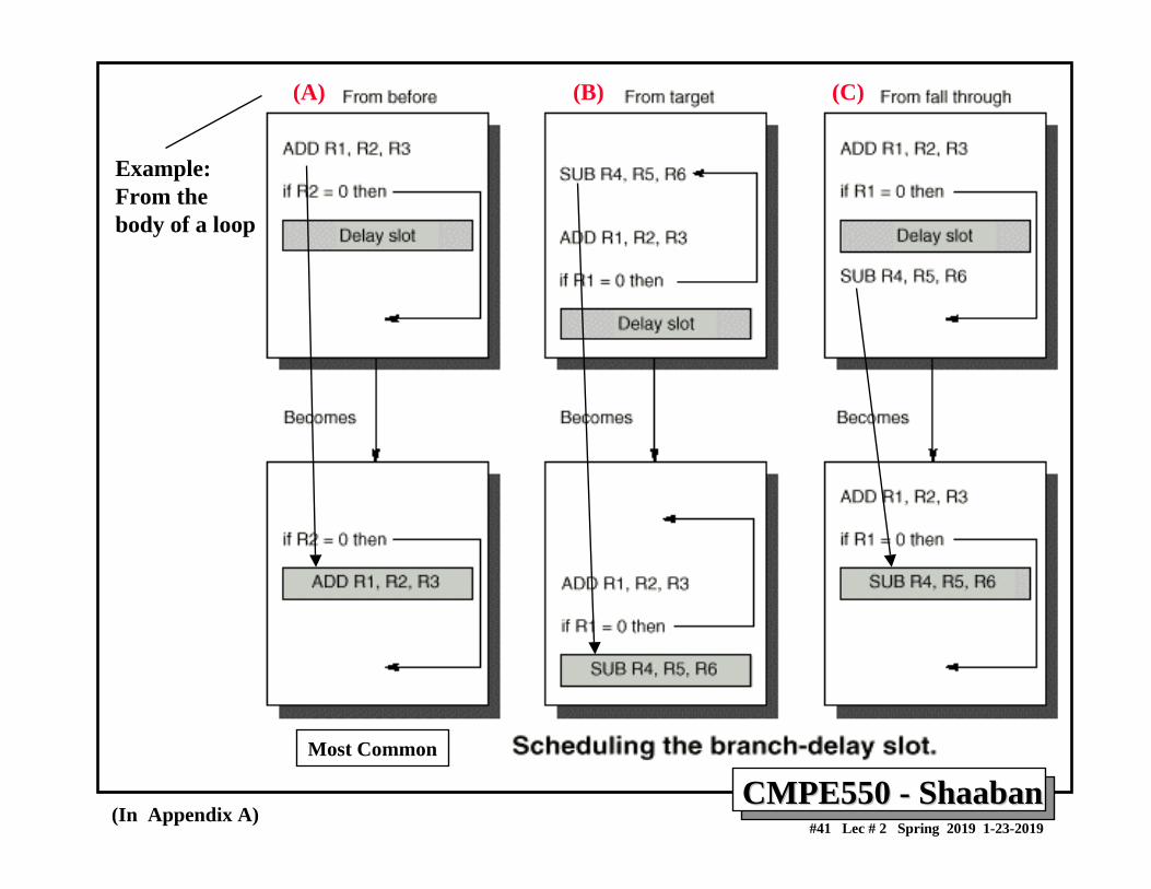
(A) (B) (C)
(In Appendix A)
Example:From the body of a loop
Most Common
CMPE550 CMPE550 -- ShaabanShaaban#42 Lec # 2 Spring 2019 1-23-2019
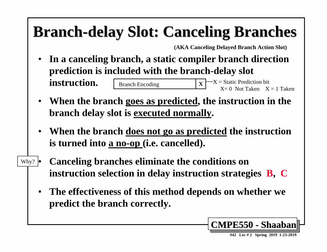
BranchBranch--delay Slot: Canceling Branchesdelay Slot: Canceling Branches• In a canceling branch, a static compiler branch direction
prediction is included with the branch-delay slot instruction.
• When the branch goes as predicted, the instruction in the branch delay slot is executed normally.
• When the branch does not go as predicted the instruction is turned into a no-op (i.e. cancelled).
• Canceling branches eliminate the conditions on instruction selection in delay instruction strategies B, C
• The effectiveness of this method depends on whether we predict the branch correctly.
XBranch Encoding X = Static Prediction bit X= 0 Not Taken X = 1 Taken
(AKA Canceling Delayed Branch Action Slot)
Why?
CMPE550 CMPE550 -- ShaabanShaaban#43 Lec # 2 Spring 2019 1-23-2019
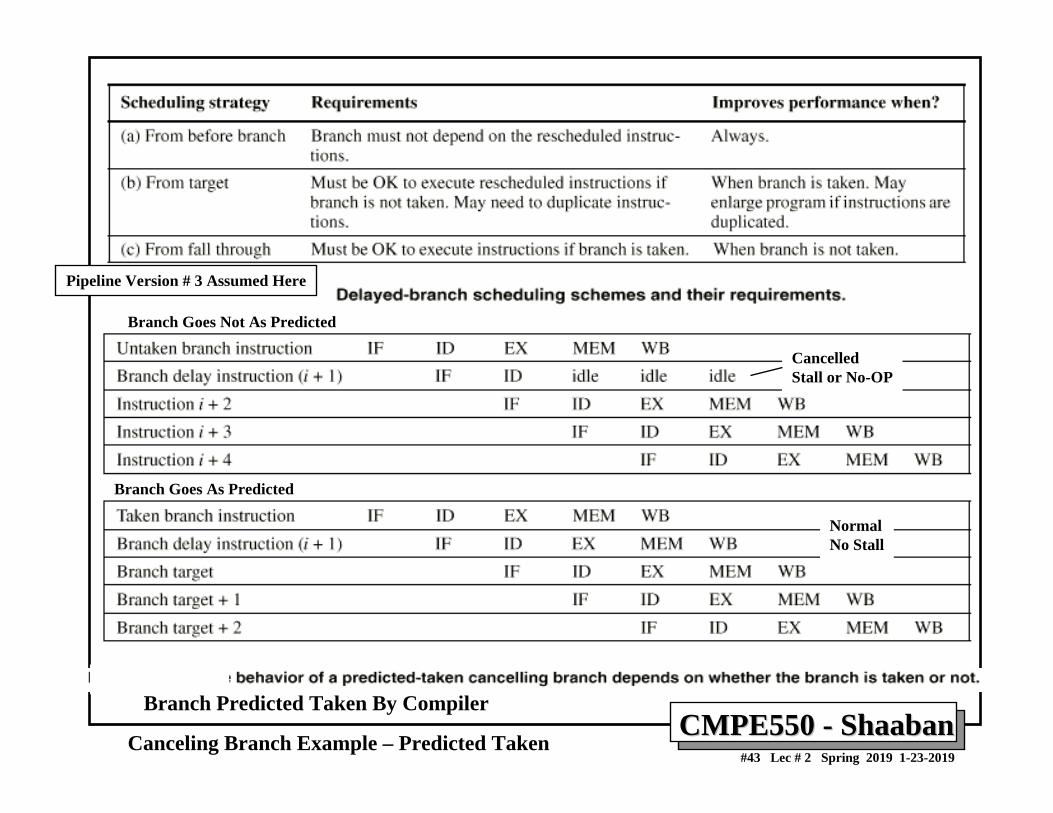
Branch Predicted Taken By Compiler
CancelledStall or No-OP
NormalNo Stall
Branch Goes Not As Predicted
Branch Goes As Predicted
Canceling Branch Example – Predicted Taken
Pipeline Version # 3 Assumed Here
CMPE550 CMPE550 -- ShaabanShaaban#44 Lec # 2 Spring 2019 1-23-2019
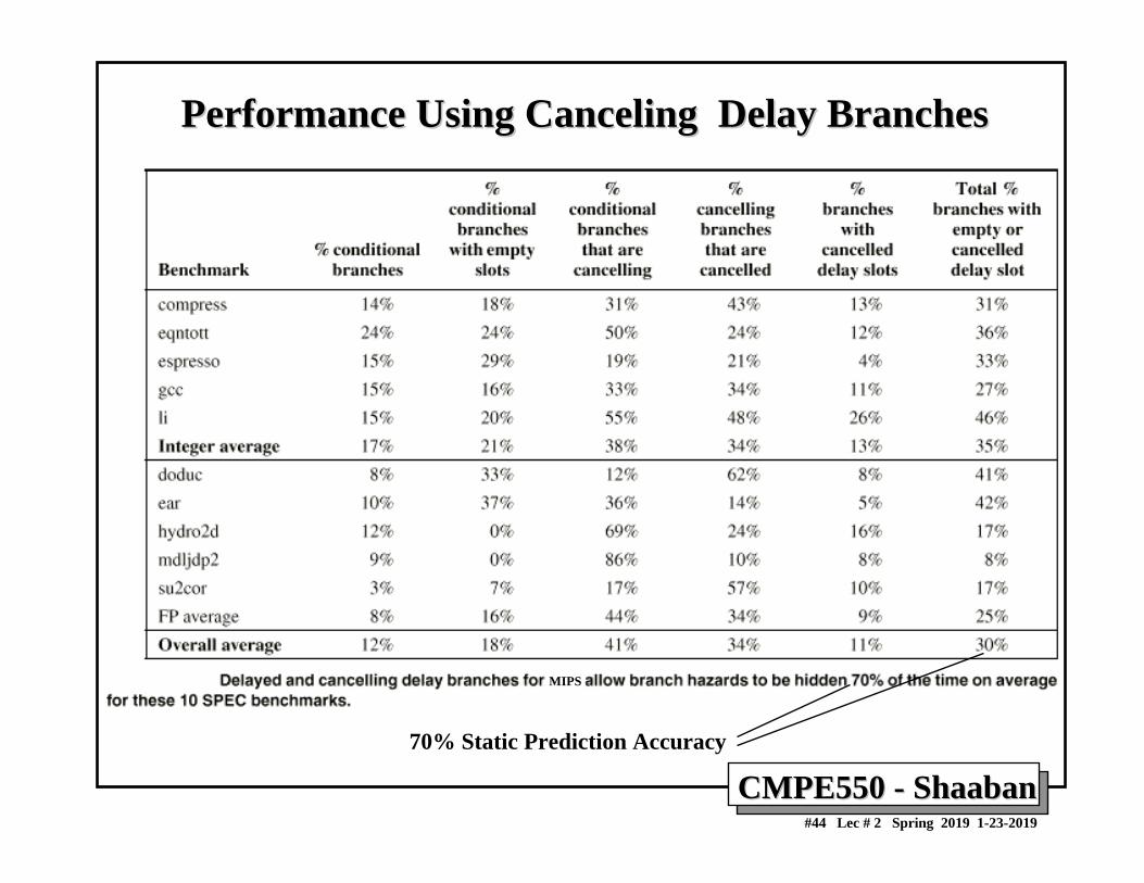
Performance Using Canceling Delay BranchesPerformance Using Canceling Delay Branches
70% Static Prediction Accuracy
MIPS
CMPE550 CMPE550 -- ShaabanShaaban#45 Lec # 2 Spring 2019 1-23-2019
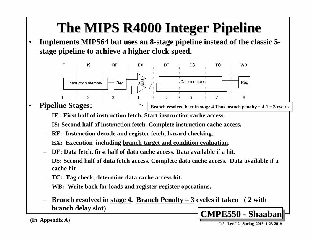
• Implements MIPS64 but uses an 8-stage pipeline instead of the classic 5-stage pipeline to achieve a higher clock speed.
• Pipeline Stages:– IF: First half of instruction fetch. Start instruction cache access.– IS: Second half of instruction fetch. Complete instruction cache access.– RF: Instruction decode and register fetch, hazard checking.– EX: Execution including branch-target and condition evaluation.– DF: Data fetch, first half of data cache access. Data available if a hit.– DS: Second half of data fetch access. Complete data cache access. Data available if a
cache hit– TC: Tag check, determine data cache access hit.– WB: Write back for loads and register-register operations.
– Branch resolved in stage 4. Branch Penalty = 3 cycles if taken ( 2 with branch delay slot)
The MIPS R4000 Integer PipelineThe MIPS R4000 Integer Pipeline
(In Appendix A)
1 2 3 4 5 6 7 8
Branch resolved here in stage 4 Thus branch penalty = 4-1 = 3 cycles
CMPE550 CMPE550 -- ShaabanShaaban#46 Lec # 2 Spring 2019 1-23-2019
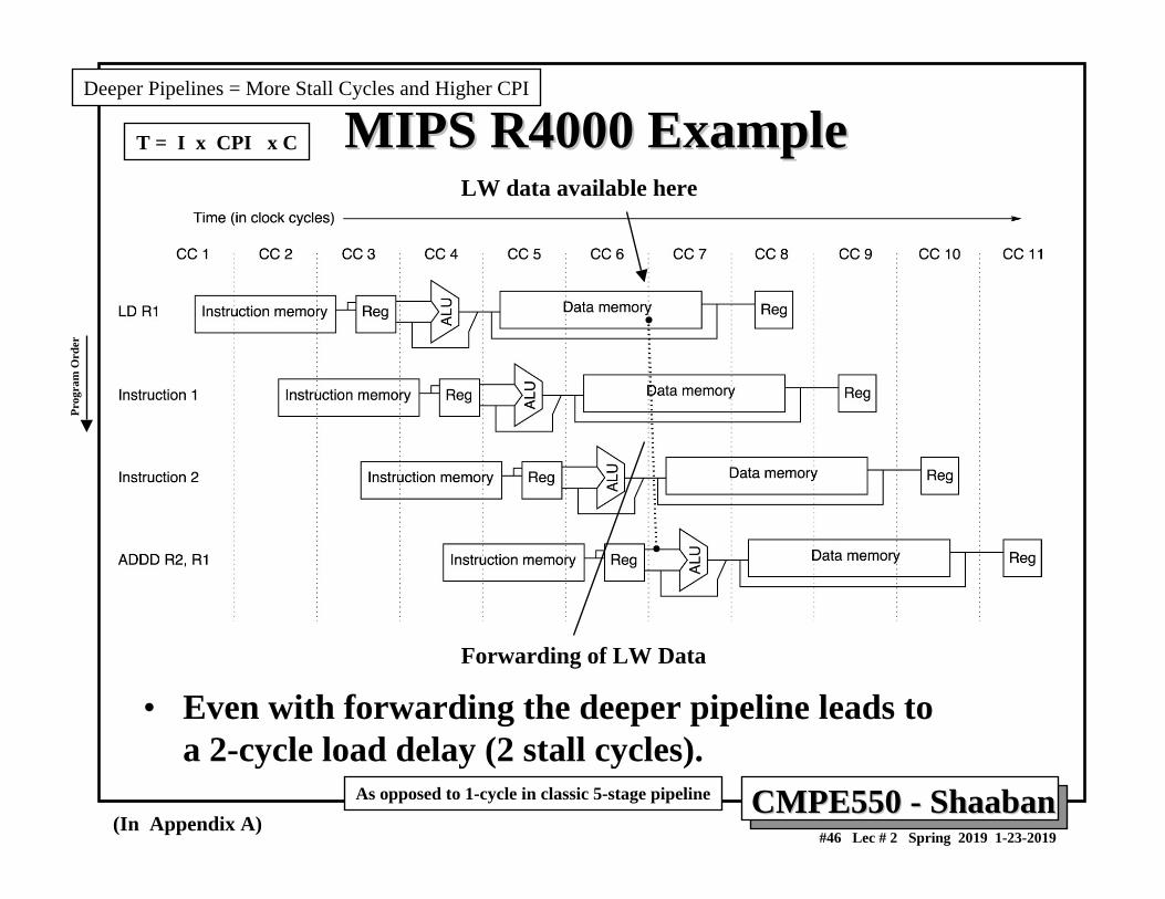
MIPS R4000 ExampleMIPS R4000 Example
• Even with forwarding the deeper pipeline leads to a 2-cycle load delay (2 stall cycles).
(In Appendix A)
LW data available here
Forwarding of LW Data
As opposed to 1-cycle in classic 5-stage pipeline
Deeper Pipelines = More Stall Cycles and Higher CPIPr
ogra
m O
rder
T = I x CPI x C
CMPE550 CMPE550 -- ShaabanShaaban#47 Lec # 2 Spring 2019 1-23-2019
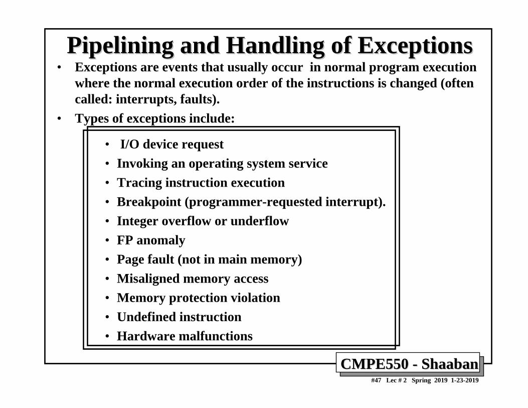
Pipelining and Handling of ExceptionsPipelining and Handling of Exceptions• Exceptions are events that usually occur in normal program execution
where the normal execution order of the instructions is changed (often called: interrupts, faults).
• Types of exceptions include:
• I/O device request • Invoking an operating system service• Tracing instruction execution• Breakpoint (programmer-requested interrupt).• Integer overflow or underflow• FP anomaly• Page fault (not in main memory)• Misaligned memory access• Memory protection violation• Undefined instruction• Hardware malfunctions
CMPE550 CMPE550 -- ShaabanShaaban#48 Lec # 2 Spring 2019 1-23-2019
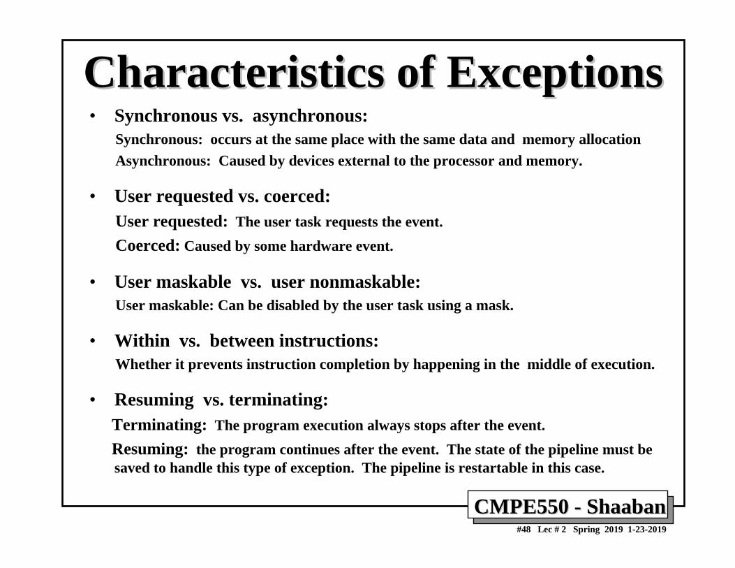
Characteristics of ExceptionsCharacteristics of Exceptions• Synchronous vs. asynchronous:
Synchronous: occurs at the same place with the same data and memory allocationAsynchronous: Caused by devices external to the processor and memory.
• User requested vs. coerced:User requested: The user task requests the event.Coerced: Caused by some hardware event.
• User maskable vs. user nonmaskable:User maskable: Can be disabled by the user task using a mask.
• Within vs. between instructions:Whether it prevents instruction completion by happening in the middle of execution.
• Resuming vs. terminating:Terminating: The program execution always stops after the event.Resuming: the program continues after the event. The state of the pipeline must be saved to handle this type of exception. The pipeline is restartable in this case.
CMPE550 CMPE550 -- ShaabanShaaban#49 Lec # 2 Spring 2019 1-23-2019
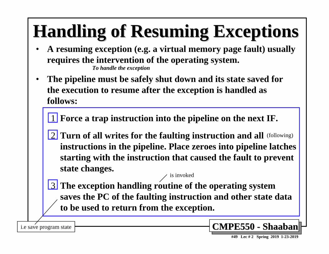
Handling of Resuming ExceptionsHandling of Resuming Exceptions• A resuming exception (e.g. a virtual memory page fault) usually
requires the intervention of the operating system.
• The pipeline must be safely shut down and its state saved for the execution to resume after the exception is handled as follows:
1 Force a trap instruction into the pipeline on the next IF.
2 Turn of all writes for the faulting instruction and all instructions in the pipeline. Place zeroes into pipeline latchesstarting with the instruction that caused the fault to prevent state changes.
3 The exception handling routine of the operating system saves the PC of the faulting instruction and other state data to be used to return from the exception.
(following)
To handle the exception
i.e save program state
is invoked
CMPE550 CMPE550 -- ShaabanShaaban#50 Lec # 2 Spring 2019 1-23-2019
Precise Exception HandlingPrecise Exception Handling• When using delayed branches, as many PCs as the the
length of the branch delay plus one need to be saved and restored to restore the state of the machine.
• After the exception has been handled special instructions are needed to return the machine to the state before the exception occurred (RFE, Return to User code in MIPS).
• Precise exceptions and handling imply that a pipeline is stopped so the instructions just before the faulting instruction are completed and and those after it can be restarted from scratch.
• Machines with arithmetic trap handlers and demand paging must support precise exceptions.
After handling the exception (i.e. As if processor is not pipelined)
i.e Precise exception handling imply handling exceptions as if the processor is not pipelines
Exception Handling Issues:Exception Handling Issues:
CMPE550 CMPE550 -- ShaabanShaaban#51 Lec # 2 Spring 2019 1-23-2019
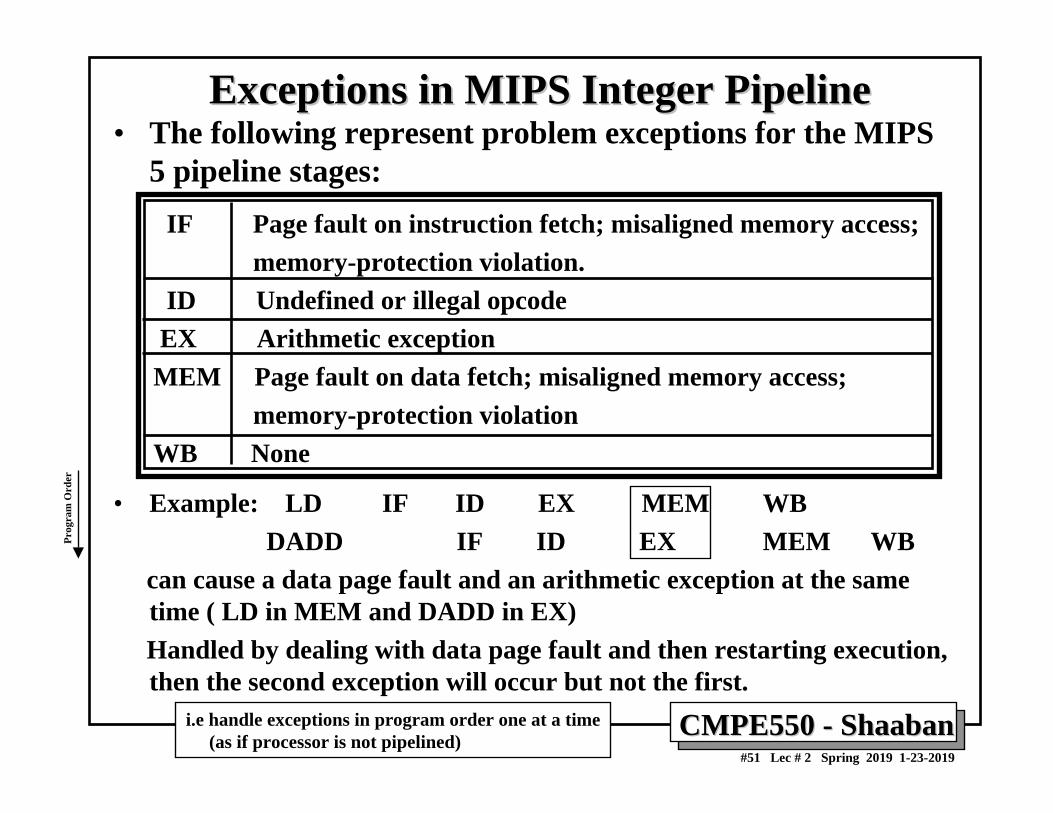
Exceptions in MIPS Integer PipelineExceptions in MIPS Integer Pipeline• The following represent problem exceptions for the MIPS
5 pipeline stages:IF Page fault on instruction fetch; misaligned memory access;
memory-protection violation.ID Undefined or illegal opcodeEX Arithmetic exceptionMEM Page fault on data fetch; misaligned memory access;
memory-protection violationWB None
• Example: LD IF ID EX MEM WBDADD IF ID EX MEM WB
can cause a data page fault and an arithmetic exception at the same time ( LD in MEM and DADD in EX) Handled by dealing with data page fault and then restarting execution, then the second exception will occur but not the first.
i.e handle exceptions in program order one at a time(as if processor is not pipelined)
Prog
ram
Ord
er
CMPE550 CMPE550 -- ShaabanShaaban#52 Lec # 2 Spring 2019 1-23-2019
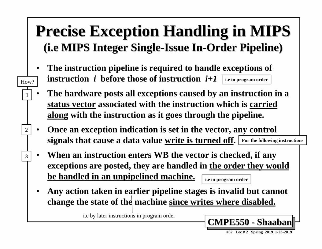
Precise Exception Handling in MIPSPrecise Exception Handling in MIPS(i.e MIPS Integer Single(i.e MIPS Integer Single--Issue InIssue In--Order Pipeline)Order Pipeline)
• The instruction pipeline is required to handle exceptions of instruction i before those of instruction i+1
• The hardware posts all exceptions caused by an instruction in a status vector associated with the instruction which is carried along with the instruction as it goes through the pipeline.
• Once an exception indication is set in the vector, any control signals that cause a data value write is turned off.
• When an instruction enters WB the vector is checked, if any exceptions are posted, they are handled in the order they would be handled in an unpipelined machine.
• Any action taken in earlier pipeline stages is invalid but cannot change the state of the machine since writes where disabled.
For the following instructions
i.e in program order
1
2
3
i.e in program orderHow?
i.e by later instructions in program order
CMPE550 CMPE550 -- ShaabanShaaban#53 Lec # 2 Spring 2019 1-23-2019
Floating Point/Multicycle Pipelining in MIPSFloating Point/Multicycle Pipelining in MIPS• Completion of MIPS EX stage floating point arithmetic operations in one
or two cycles is impractical since it requires:• A much longer CPU clock cycle, and/or• An enormous amount of logic.
• Instead, the floating-point pipeline will allow for a longer latency (more EX cycles than 1).
• Floating-point operations have the same pipeline stages as the integer instructions with the following differences:
– The EX cycle may be repeated as many times as needed (more than 1 cycle).
– There may be multiple floating-point functional units.– A stall will occur if the instruction to be issued either causes a structural
hazard for the functional unit or cause a data hazard.
• The latency of functional units is defined as the number of intervening cycles between an instruction producing the result and the instruction that uses the result (usually equals stall cycles with forwarding used).
• The initiation or repeat interval is the number of cycles that must elapse between issuing an instruction of a given type.
(In Appendix A)
Solution:
to the same functional unit
(Stall?)
CMPE550 CMPE550 -- ShaabanShaaban#54 Lec # 2 Spring 2019 1-23-2019
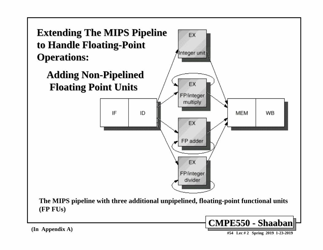
Extending The MIPS PipelineExtending The MIPS Pipelineto Handle Floatingto Handle Floating--Point Point Operations:Operations:
Adding NonAdding Non--PipelinedPipelinedFloating Point UnitsFloating Point Units
(In Appendix A)
The MIPS pipeline with three additional unpipelined, floating-point functional units (FP FUs)
CMPE550 CMPE550 -- ShaabanShaaban#55 Lec # 2 Spring 2019 1-23-2019
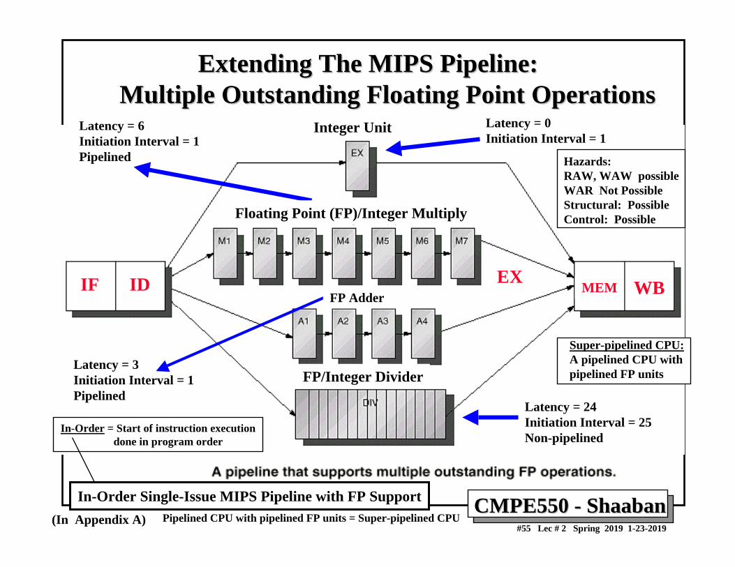
Extending The MIPS Pipeline:Extending The MIPS Pipeline:Multiple Outstanding Floating Point OperationsMultiple Outstanding Floating Point Operations
Latency = 0Initiation Interval = 1
Latency = 3Initiation Interval = 1Pipelined
Latency = 6Initiation Interval = 1Pipelined
Latency = 24Initiation Interval = 25Non-pipelined
Integer Unit
Floating Point (FP)/Integer Multiply
FP/Integer Divider
IF ID WBMEMFP Adder
EX
Hazards:RAW, WAW possibleWAR Not PossibleStructural: PossibleControl: Possible
(In Appendix A)
In-Order Single-Issue MIPS Pipeline with FP SupportPipelined CPU with pipelined FP units = Super-pipelined CPU
Super-pipelined CPU:A pipelined CPU withpipelined FP units
In-Order = Start of instruction executiondone in program order
CMPE550 CMPE550 -- ShaabanShaaban#56 Lec # 2 Spring 2019 1-23-2019
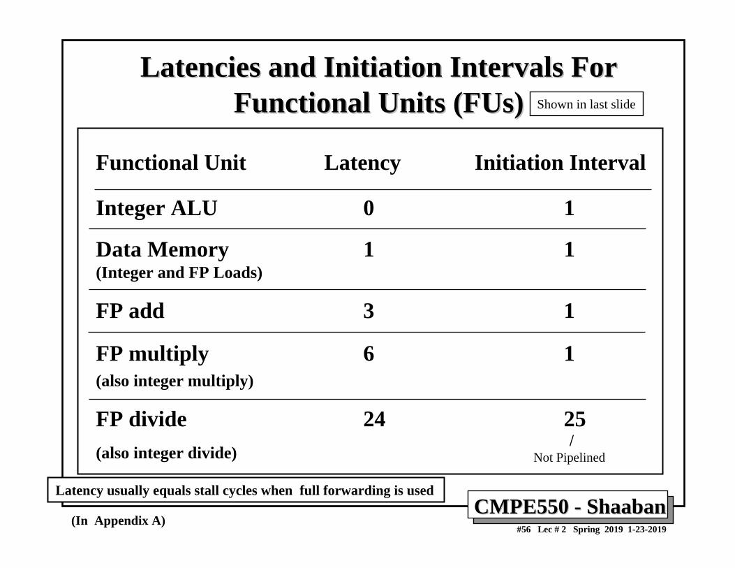
Latencies and Initiation Intervals For Latencies and Initiation Intervals For Functional Units (FUs)Functional Units (FUs)
Functional Unit Latency Initiation Interval
Integer ALU 0 1
Data Memory 1 1(Integer and FP Loads)
FP add 3 1
FP multiply 6 1(also integer multiply)
FP divide 24 25(also integer divide)
Latency usually equals stall cycles when full forwarding is used
(In Appendix A)
Shown in last slide
Not Pipelined
CMPE550 CMPE550 -- ShaabanShaaban#57 Lec # 2 Spring 2019 1-23-2019
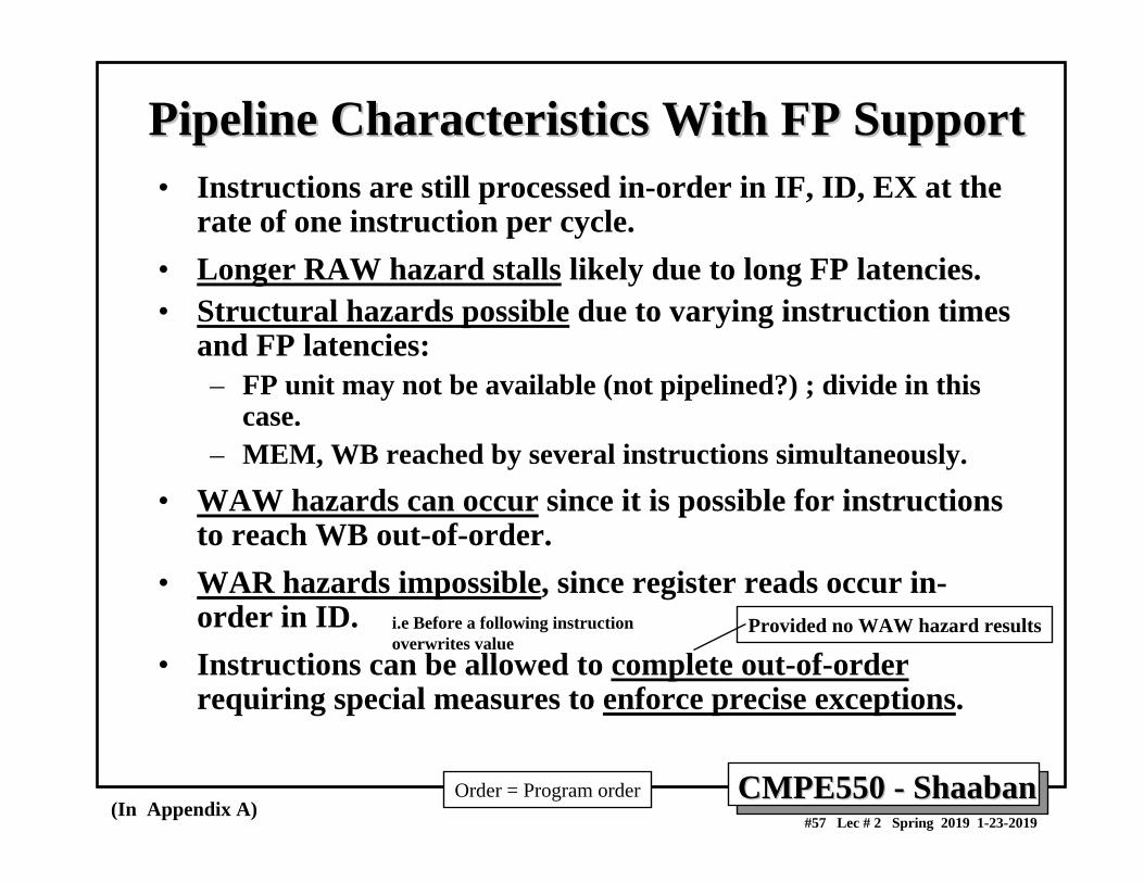
Pipeline Characteristics With FP SupportPipeline Characteristics With FP Support• Instructions are still processed in-order in IF, ID, EX at the
rate of one instruction per cycle.• Longer RAW hazard stalls likely due to long FP latencies.• Structural hazards possible due to varying instruction times
and FP latencies: – FP unit may not be available (not pipelined?) ; divide in this
case.– MEM, WB reached by several instructions simultaneously.
• WAW hazards can occur since it is possible for instructions to reach WB out-of-order.
• WAR hazards impossible, since register reads occur in-order in ID.
• Instructions can be allowed to complete out-of-orderrequiring special measures to enforce precise exceptions.
(In Appendix A)
Provided no WAW hazard resultsi.e Before a following instruction overwrites value
Order = Program order
CMPE550 CMPE550 -- ShaabanShaaban#58 Lec # 2 Spring 2019 1-23-2019
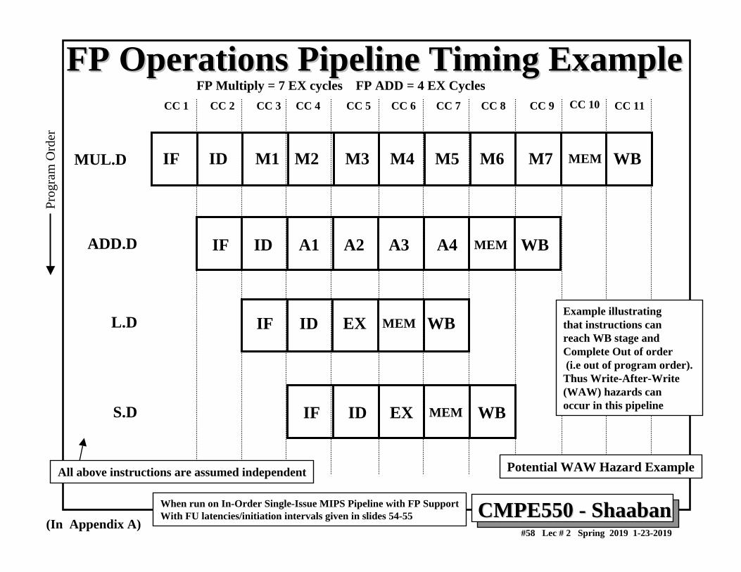
FP Operations Pipeline Timing ExampleFP Operations Pipeline Timing Example
IF ID A1 A4A3A2 MEM WB
IF ID M1 M6 M7M2 M3 M4 M5 MEM WB
IF ID MEMEX WB
IF ID MEMEX WB
MUL.D
L.D
ADD.D
S.D
CC 1 CC 2 CC 3 CC 8 CC 9CC 4 CC 5 CC 6 CC 7 CC 10 CC 11
(In Appendix A)
When run on In-Order Single-Issue MIPS Pipeline with FP SupportWith FU latencies/initiation intervals given in slides 54-55
Example illustrating that instructions can reach WB stage and Complete Out of order(i.e out of program order). Thus Write-After-Write (WAW) hazards can occur in this pipeline
All above instructions are assumed independent
Prog
ram
Ord
er
Potential WAW Hazard Example
FP Multiply = 7 EX cycles FP ADD = 4 EX Cycles
CMPE550 CMPE550 -- ShaabanShaaban#59 Lec # 2 Spring 2019 1-23-2019
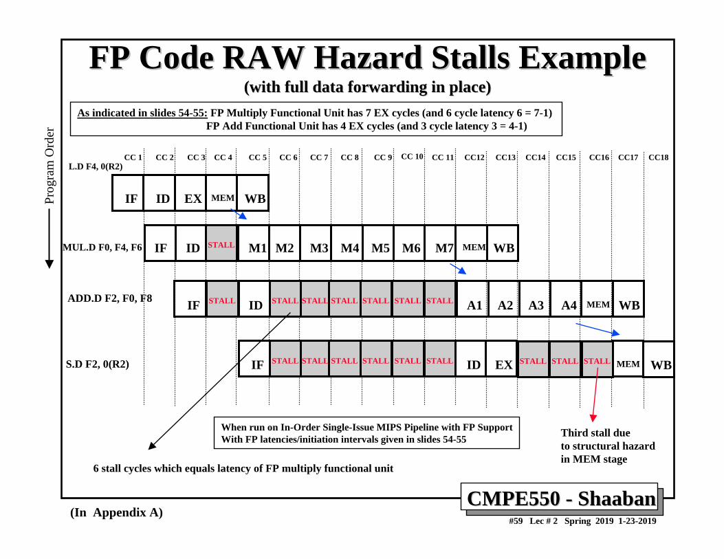
FP Code RAW Hazard Stalls ExampleFP Code RAW Hazard Stalls Example(with full data forwarding in place)(with full data forwarding in place)
IF MEMID EX WB
IF ID M1 M6 M7M2 M3 M4 M5 MEM WB
IF ID A1 A4A3A2 MEM WB
CC 1 CC 2 CC 3 CC 8 CC 9CC 4 CC 5 CC 6 CC 7 CC 10 CC 11 CC12 CC13 CC14 CC15 CC16 CC17 CC18
IF ID MEMEX WB
STALL
STALL STALL STALL STALLSTALL STALL STALL
STALL STALLSTALL STALL STALL STALL STALL STALL STALL
L.D F4, 0(R2)
MUL.D F0, F4, F6
ADD.D F2, F0, F8
S.D F2, 0(R2)
Third stall dueto structural hazard in MEM stage
6 stall cycles which equals latency of FP multiply functional unit
(In Appendix A)
When run on In-Order Single-Issue MIPS Pipeline with FP SupportWith FP latencies/initiation intervals given in slides 54-55
Prog
ram
Ord
er
As indicated in slides 54-55: FP Multiply Functional Unit has 7 EX cycles (and 6 cycle latency 6 = 7-1) FP Add Functional Unit has 4 EX cycles (and 3 cycle latency 3 = 4-1)
CMPE550 CMPE550 -- ShaabanShaaban#60 Lec # 2 Spring 2019 1-23-2019
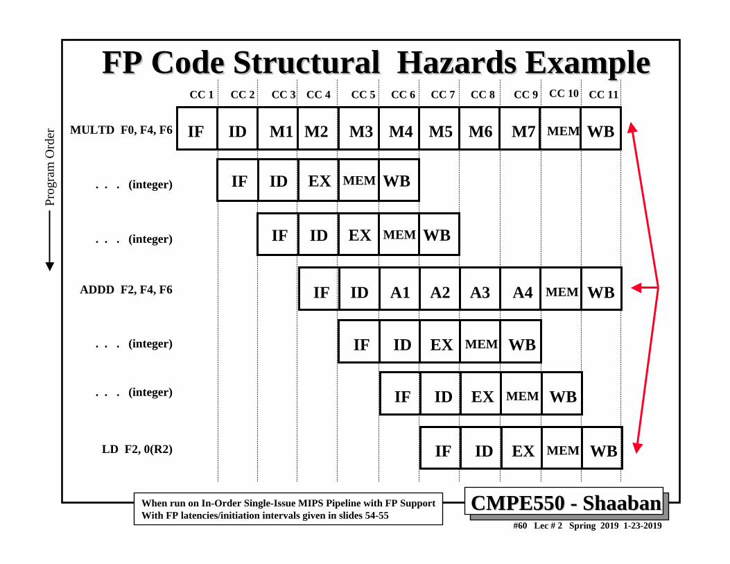
FP Code Structural Hazards ExampleFP Code Structural Hazards Example
IF ID A1 A4A3A2 MEM WB
IF ID M1 M6 M7M2 M3 M4 M5 MEM WB
IF ID MEMEX WB
IF ID MEMEX WB
MULTD F0, F4, F6
LD F2, 0(R2)
ADDD F2, F4, F6
CC 1 CC 2 CC 3 CC 8 CC 9CC 4 CC 5 CC 6 CC 7 CC 10 CC 11
IF ID MEMEX WB
IF ID MEMEX WB
IF ID MEMEX WB
. . . (integer)
. . . (integer)
. . . (integer)
. . . (integer)
When run on In-Order Single-Issue MIPS Pipeline with FP SupportWith FP latencies/initiation intervals given in slides 54-55
Prog
ram
Ord
er
CMPE550 CMPE550 -- ShaabanShaaban#61 Lec # 2 Spring 2019 1-23-2019
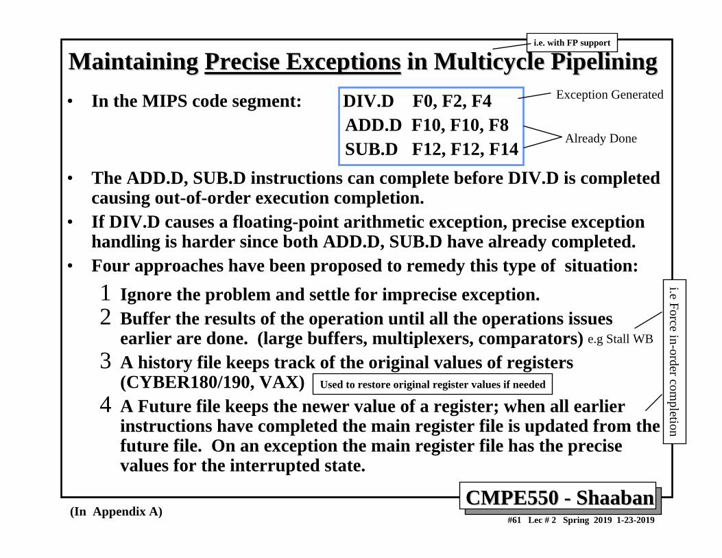
Maintaining Maintaining Precise ExceptionsPrecise Exceptions in Multicycle Pipeliningin Multicycle Pipelining• In the MIPS code segment: DIV.D F0, F2, F4
ADD.D F10, F10, F8SUB.D F12, F12, F14
• The ADD.D, SUB.D instructions can complete before DIV.D is completed causing out-of-order execution completion.
• If DIV.D causes a floating-point arithmetic exception, precise exception handling is harder since both ADD.D, SUB.D have already completed.
• Four approaches have been proposed to remedy this type of situation:1 Ignore the problem and settle for imprecise exception.2 Buffer the results of the operation until all the operations issues
earlier are done. (large buffers, multiplexers, comparators)3 A history file keeps track of the original values of registers
(CYBER180/190, VAX)4 A Future file keeps the newer value of a register; when all earlier
instructions have completed the main register file is updated from the future file. On an exception the main register file has the precise values for the interrupted state.
(In Appendix A)
e.g Stall WB
Exception Generated
Already Done
Used to restore original register values if needed
i.e Force in-order completion
i.e. with FP support