Embed Size (px)
Citation preview

Designation: C1249 – 06a (Reapproved 2010)
Standard Guide forSecondary Seal for Sealed Insulating Glass Units forStructural Sealant Glazing Applications1
This standard is issued under the fixed designation C1249; the number immediately following the designation indicates the year oforiginal adoption or, in the case of revision, the year of last revision. A number in parentheses indicates the year of last reapproval. Asuperscript epsilon (´) indicates an editorial change since the last revision or reapproval.
1. Scope
1.1 This guide covers design and fabrication considerationsfor the edge seal of conventionally sealed insulating glassunits, herein referred to as IG units. The IG units described areused in structural silicone sealant glazing systems, hereinreferred to as SSG systems. SSG systems typically are eithertwo or four sided, glazed with a structural sealant. Otherconditions such as one, three, five, six sided may be used.
1.2 This guides does not cover the IG units of other thanconventional edge seal design (Fig. 1); however, the informa-tion contained herein may be of benefit to the designers of suchIG units.
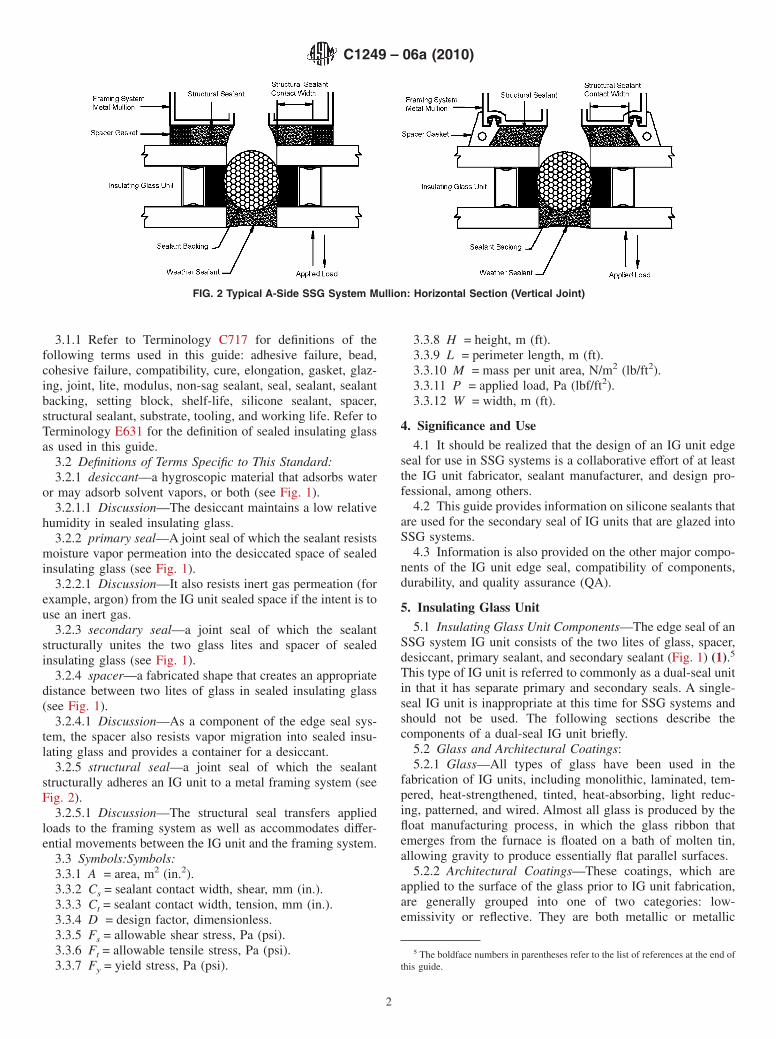
1.3 In an SSG system, IG units are retained to a metalframing system by a structural seal (Fig. 2). The size and shapeof that seal, as well as numerous other SSG system designconsiderations, are not addressed in this guide.
1.4 The values stated in SI units are to be regarded as thestandard. The values given in parentheses are for informationonly.
1.5 This standard does not purport to address all of thesafety problems, if any, associated with its use. It is theresponsibility of the user of this standard to establish appro-priate safety and health practices and determine the applica-bility of regulatory limitations prior to use.
1.6 The committee with jurisdiction for this standard is notaware of any comparable standard guides published by otherorganizations.
2. Referenced Documents
2.1 ASTM Standards:2
C639 Test Method for Rheological (Flow) Properties ofElastomeric Sealants
C679 Test Method for Tack-Free Time of ElastomericSealants
C717 Terminology of Building Seals and SealantsC794 Test Method for Adhesion-in-Peel of Elastomeric
Joint SealantsC1087 Test Method for Determining Compatibility of
Liquid-Applied Sealants with Accessories Used in Struc-tural Glazing Systems
C1135 Test Method for Determining Tensile AdhesionProperties of Structural Sealants
C1184 Specification for Structural Silicone SealantsE631 Terminology of Building ConstructionsE773 Test Method for Accelerated Weathering of Sealed
Insulating Glass Units3
E774 Specification for the Classification of the Durability ofSealed Insulating Glass Units3
E2188 Test Method for Insulating Glass Unit PerformanceE2189 Test Method for Testing Resistance to Fogging in
Insulating Glass UnitsE2190 Specification for Insulating Glass Unit Performance
and Evaluation2.2 Other Standards:Igma 73-8-2B Test Methods for Chemical Effects of
Glazing Compounds on Elastomeric Edge Seals4
3. Terminology
3.1 Definitions:
1 This guide is under the jurisdiction of ASTM Committee C24 on Building Sealsand Sealants and is the direct responsibility of Subcommittee C24.10 on Specifi-cations, Guides and Practices.
Current edition approved June 1, 2010. Published July 2010. Originally approvedin 1993. Last previous edition approved in 2006 as C1249–06a. DOI: 10.1520/C1249-06AR10.
2 For referenced ASTM standards, visit the ASTM website, www.astm.org, orcontact ASTM Customer Service at [email protected]. For Annual Book of ASTMStandards volume information, refer to the standard’s Document Summary page onthe ASTM website.
3 Withdrawn. The last approved version of this historical standard is referencedon www.astm.org.
4 Available from IGMA, 111 E. Wacker Dr., Ste. 600, Chicago, IL 60601.
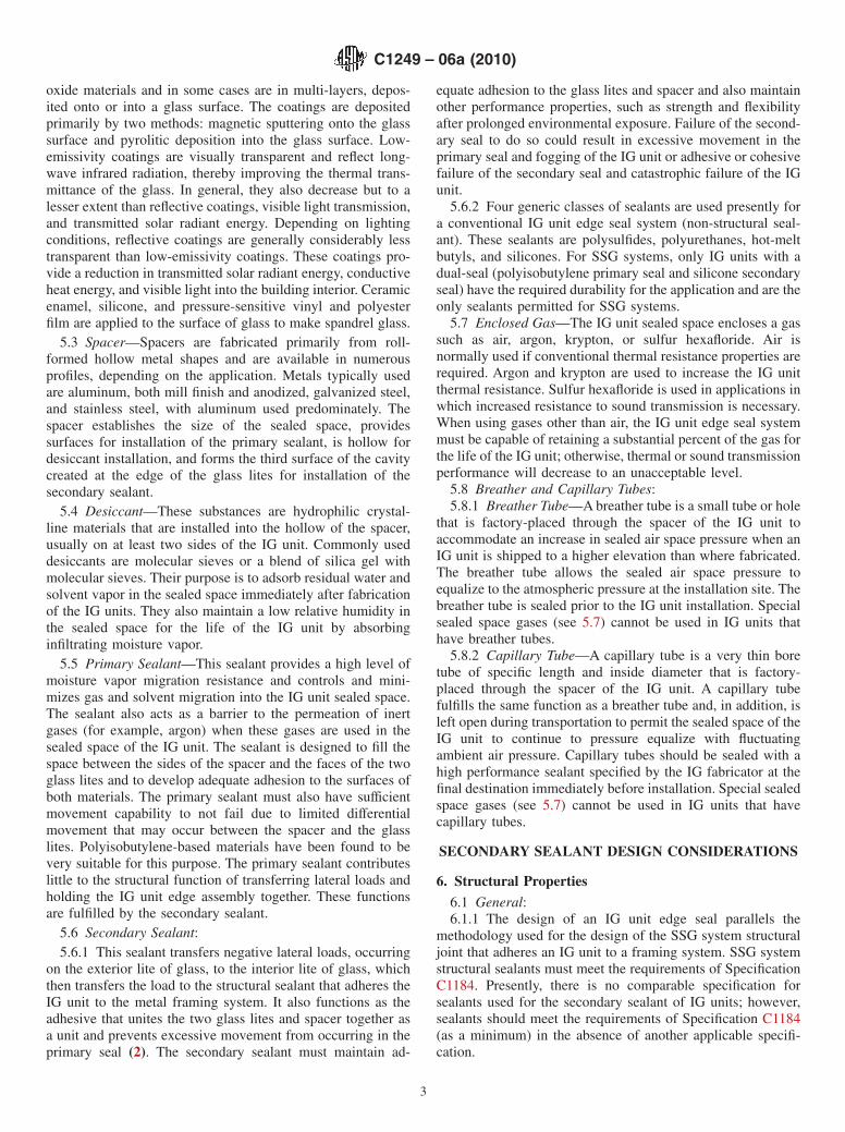
FIG. 1 Sealed IG Edge Seal: Basic Components
1
Copyright © ASTM International, 100 Barr Harbor Drive, PO Box C700, West Conshohocken, PA 19428-2959, United States.
3.1.1 Refer to Terminology C717 for definitions of thefollowing terms used in this guide: adhesive failure, bead,cohesive failure, compatibility, cure, elongation, gasket, glaz-ing, joint, lite, modulus, non-sag sealant, seal, sealant, sealantbacking, setting block, shelf-life, silicone sealant, spacer,structural sealant, substrate, tooling, and working life. Refer toTerminology E631 for the definition of sealed insulating glassas used in this guide.
3.2 Definitions of Terms Specific to This Standard:3.2.1 desiccant—a hygroscopic material that adsorbs water
or may adsorb solvent vapors, or both (see Fig. 1).3.2.1.1 Discussion—The desiccant maintains a low relative
humidity in sealed insulating glass.3.2.2 primary seal—A joint seal of which the sealant resists
moisture vapor permeation into the desiccated space of sealedinsulating glass (see Fig. 1).
3.2.2.1 Discussion—It also resists inert gas permeation (forexample, argon) from the IG unit sealed space if the intent is touse an inert gas.
3.2.3 secondary seal—a joint seal of which the sealantstructurally unites the two glass lites and spacer of sealedinsulating glass (see Fig. 1).
3.2.4 spacer—a fabricated shape that creates an appropriatedistance between two lites of glass in sealed insulating glass(see Fig. 1).
3.2.4.1 Discussion—As a component of the edge seal sys-tem, the spacer also resists vapor migration into sealed insu-lating glass and provides a container for a desiccant.
3.2.5 structural seal—a joint seal of which the sealantstructurally adheres an IG unit to a metal framing system (seeFig. 2).
3.2.5.1 Discussion—The structural seal transfers appliedloads to the framing system as well as accommodates differ-ential movements between the IG unit and the framing system.
3.3 Symbols:Symbols:3.3.1 A = area, m2 (in.2).3.3.2 Cs = sealant contact width, shear, mm (in.).3.3.3 Ct = sealant contact width, tension, mm (in.).3.3.4 D = design factor, dimensionless.3.3.5 Fs = allowable shear stress, Pa (psi).3.3.6 Ft = allowable tensile stress, Pa (psi).3.3.7 Fy = yield stress, Pa (psi).
3.3.8 H = height, m (ft).3.3.9 L = perimeter length, m (ft).3.3.10 M = mass per unit area, N/m2 (lb/ft2).3.3.11 P = applied load, Pa (lbf/ft2).3.3.12 W = width, m (ft).
4. Significance and Use
4.1 It should be realized that the design of an IG unit edgeseal for use in SSG systems is a collaborative effort of at leastthe IG unit fabricator, sealant manufacturer, and design pro-fessional, among others.
4.2 This guide provides information on silicone sealants thatare used for the secondary seal of IG units that are glazed intoSSG systems.
4.3 Information is also provided on the other major compo-nents of the IG unit edge seal, compatibility of components,durability, and quality assurance (QA).
5. Insulating Glass Unit
5.1 Insulating Glass Unit Components—The edge seal of anSSG system IG unit consists of the two lites of glass, spacer,desiccant, primary sealant, and secondary sealant (Fig. 1) (1).5
This type of IG unit is referred to commonly as a dual-seal unitin that it has separate primary and secondary seals. A single-seal IG unit is inappropriate at this time for SSG systems andshould not be used. The following sections describe thecomponents of a dual-seal IG unit briefly.
5.2 Glass and Architectural Coatings:5.2.1 Glass—All types of glass have been used in the
fabrication of IG units, including monolithic, laminated, tem-pered, heat-strengthened, tinted, heat-absorbing, light reduc-ing, patterned, and wired. Almost all glass is produced by thefloat manufacturing process, in which the glass ribbon thatemerges from the furnace is floated on a bath of molten tin,allowing gravity to produce essentially flat parallel surfaces.
5.2.2 Architectural Coatings—These coatings, which areapplied to the surface of the glass prior to IG unit fabrication,are generally grouped into one of two categories: low-emissivity or reflective. They are both metallic or metallic
5 The boldface numbers in parentheses refer to the list of references at the end ofthis guide.
FIG. 2 Typical A-Side SSG System Mullion: Horizontal Section (Vertical Joint)
C1249 – 06a (2010)
2
oxide materials and in some cases are in multi-layers, depos-ited onto or into a glass surface. The coatings are depositedprimarily by two methods: magnetic sputtering onto the glasssurface and pyrolitic deposition into the glass surface. Low-emissivity coatings are visually transparent and reflect long-wave infrared radiation, thereby improving the thermal trans-mittance of the glass. In general, they also decrease but to alesser extent than reflective coatings, visible light transmission,and transmitted solar radiant energy. Depending on lightingconditions, reflective coatings are generally considerably lesstransparent than low-emissivity coatings. These coatings pro-vide a reduction in transmitted solar radiant energy, conductiveheat energy, and visible light into the building interior. Ceramicenamel, silicone, and pressure-sensitive vinyl and polyesterfilm are applied to the surface of glass to make spandrel glass.
5.3 Spacer—Spacers are fabricated primarily from roll-formed hollow metal shapes and are available in numerousprofiles, depending on the application. Metals typically usedare aluminum, both mill finish and anodized, galvanized steel,and stainless steel, with aluminum used predominately. Thespacer establishes the size of the sealed space, providessurfaces for installation of the primary sealant, is hollow fordesiccant installation, and forms the third surface of the cavitycreated at the edge of the glass lites for installation of thesecondary sealant.
5.4 Desiccant—These substances are hydrophilic crystal-line materials that are installed into the hollow of the spacer,usually on at least two sides of the IG unit. Commonly useddesiccants are molecular sieves or a blend of silica gel withmolecular sieves. Their purpose is to adsorb residual water andsolvent vapor in the sealed space immediately after fabricationof the IG units. They also maintain a low relative humidity inthe sealed space for the life of the IG unit by absorbinginfiltrating moisture vapor.
5.5 Primary Sealant—This sealant provides a high level ofmoisture vapor migration resistance and controls and mini-mizes gas and solvent migration into the IG unit sealed space.The sealant also acts as a barrier to the permeation of inertgases (for example, argon) when these gases are used in thesealed space of the IG unit. The sealant is designed to fill thespace between the sides of the spacer and the faces of the twoglass lites and to develop adequate adhesion to the surfaces ofboth materials. The primary sealant must also have sufficientmovement capability to not fail due to limited differentialmovement that may occur between the spacer and the glasslites. Polyisobutylene-based materials have been found to bevery suitable for this purpose. The primary sealant contributeslittle to the structural function of transferring lateral loads andholding the IG unit edge assembly together. These functionsare fulfilled by the secondary sealant.
5.6 Secondary Sealant:5.6.1 This sealant transfers negative lateral loads, occurring
on the exterior lite of glass, to the interior lite of glass, whichthen transfers the load to the structural sealant that adheres theIG unit to the metal framing system. It also functions as theadhesive that unites the two glass lites and spacer together asa unit and prevents excessive movement from occurring in theprimary seal (2). The secondary sealant must maintain ad-
equate adhesion to the glass lites and spacer and also maintainother performance properties, such as strength and flexibilityafter prolonged environmental exposure. Failure of the second-ary seal to do so could result in excessive movement in theprimary seal and fogging of the IG unit or adhesive or cohesivefailure of the secondary seal and catastrophic failure of the IGunit.
5.6.2 Four generic classes of sealants are used presently fora conventional IG unit edge seal system (non-structural seal-ant). These sealants are polysulfides, polyurethanes, hot-meltbutyls, and silicones. For SSG systems, only IG units with adual-seal (polyisobutylene primary seal and silicone secondaryseal) have the required durability for the application and are theonly sealants permitted for SSG systems.
5.7 Enclosed Gas—The IG unit sealed space encloses a gassuch as air, argon, krypton, or sulfur hexafloride. Air isnormally used if conventional thermal resistance properties arerequired. Argon and krypton are used to increase the IG unitthermal resistance. Sulfur hexafloride is used in applications inwhich increased resistance to sound transmission is necessary.When using gases other than air, the IG unit edge seal systemmust be capable of retaining a substantial percent of the gas forthe life of the IG unit; otherwise, thermal or sound transmissionperformance will decrease to an unacceptable level.
5.8 Breather and Capillary Tubes:5.8.1 Breather Tube—A breather tube is a small tube or hole
that is factory-placed through the spacer of the IG unit toaccommodate an increase in sealed air space pressure when anIG unit is shipped to a higher elevation than where fabricated.The breather tube allows the sealed air space pressure toequalize to the atmospheric pressure at the installation site. Thebreather tube is sealed prior to the IG unit installation. Specialsealed space gases (see 5.7) cannot be used in IG units thathave breather tubes.
5.8.2 Capillary Tube—A capillary tube is a very thin boretube of specific length and inside diameter that is factory-placed through the spacer of the IG unit. A capillary tubefulfills the same function as a breather tube and, in addition, isleft open during transportation to permit the sealed space of theIG unit to continue to pressure equalize with fluctuatingambient air pressure. Capillary tubes should be sealed with ahigh performance sealant specified by the IG fabricator at thefinal destination immediately before installation. Special sealedspace gases (see 5.7) cannot be used in IG units that havecapillary tubes.
SECONDARY SEALANT DESIGN CONSIDERATIONS
6. Structural Properties
6.1 General:6.1.1 The design of an IG unit edge seal parallels the
methodology used for the design of the SSG system structuraljoint that adheres an IG unit to a framing system. SSG systemstructural sealants must meet the requirements of SpecificationC1184. Presently, there is no comparable specification forsealants used for the secondary sealant of IG units; however,sealants should meet the requirements of Specification C1184(as a minimum) in the absence of another applicable specifi-cation.
C1249 – 06a (2010)
3
6.1.2 The following sections provide the design profes-sional with information on the design of the IG unit edge sealsecondary sealant regarding the following: allowable tensilestrength; modulus properties; appropriate design factors; anddesign of the secondary sealant for the effects of shear stress,tensile stress, and combined stresses.
6.2 Sealant Yield Stress—The minimum sealant yield stress(Fu) (or tensile adhesion value) is determined by Test MethodC1135 by pulling to failure small laboratory specimens ofsealant having a cross-section similar (but not necessarilyidentical) to that used in a structural seal. Sealant manufactur-ers usually report this value in a table of performance criteriafor a particular sealant. An example of a sealant manufacturer’sreported value for Fu would be 896 kPa (130 psi) for a two-parthigh-modulus sealant.
6.3 Sealant Tensile Stress:6.3.1 The allowable sealant tensile stress (Ft) for SSG
system structural seals is determined by dividing the ultimatestress (Fu) by an appropriate design factor (D) ((Eq 1)).
Ft 5 Fu/D (1)
6.3.2 For example, using a manufacturer’s published ulti-mate stress (Fy) for a sealant of 559 kPa (80 psi), with a designfactor (D) of 4.0, and substituting these values into (Eq 1),results in the following:
Ft 5 559/4.0 5 138 kPa (2)
or
Ft 5 80/4.0 5 20 psi (3)
6.3.3 Current industry practice for the structural seal of anSSG system, which was determined empirically, is to limit thevalue of Ft to 138 kPa (20 psi). The SSG system structural sealcontact width (Fig. 2) is usually established using the appliedlateral load, acting in tension, in conjunction with the 138 kPa(20 psi) tensile stress. Additional contributory stresses from,for example, thermal movement, dead load (see 6.6), sealantcross-section dimension, non-linear glass deflection underload, internal sealant stress due to cure shrinkage, prestress insealant due to differential building component movement, andvariation in sealant physical properties can also influence thisvalue. If these additional factors are a significant concern, anallowable tensile stress (Ft) of below 138 kPa (20 psi) may beappropriate for the SSG system structural seal sealant.
6.3.4 Regarding the secondary sealant for IG units, some IGunit fabricators recommend using values for Ft such as 207 kPa(30 psi) in lieu of the more conservative 138 kPa (20 psi) valueused for the SSG system structural seal. The rationale for usinghigher values for Ft is the already high quality of the fabrica-tor’s QA program for fabricating the IG unit edge seal. BetterQA results in more consistent adhesion of the secondarysealant, and higher values for Ft can therefore be maintainedreliably. In addition, the cladding design load is usually chosenas the maximum to occur in a 50 or sometimes 100-year returnperiod. Because of this, the actual tensile stress on thesecondary sealant is typically a lower value and in some areasa relatively small percentage of the Fu value. If a value of Ft inexcess of 138 kPa (20 psi) is proposed, it must be evaluated
carefully. This careful evaluation is especially significant sinceFt does not give significance to the additional stress factorsdiscussed in 6.3.3.
6.3.5 Presently, for the IG unit secondary sealant, the stressin the secondary sealant is usually limited to 138 kPa (20 psi).The applied lateral load, which is shared between the two litesof glass of the IG unit, in conjunction with the 138 kPa (20 psi)limit, is used to calculate the secondary sealant contact widthrequired to resist the applied lateral load (see 6.7). This equalload sharing is applied only when the two lites are of equalthickness.
6.3.6 It is not within the scope of this guide to specify aparticular tensile stress (Ft) for the IG unit secondary sealant.This should be an informed decision made by the designprofessional, in conjunction with the structural sealant manu-facturer and IG unit fabricator, considering, among otherfactors: building code requirements, degree of risk, and theparticular SSG system and IG unit requirements.
6.4 Design Factor:6.4.1 For SSG system structural seals, a factor ranging from
4 to 12 was originally selected for the structural sealant duringthe beginnings of SSG technology. This range recognized themany variables and unknowns, such as determining appliedloads and load distribution accurately, the relatively poor tearstrength if three-sided adhesion occurred, and the difficulty ofdetermining the actual sealant stress. This approach is consis-tent with traditional engineering practice, in which uncertaintyand unknowns are mitigated to a certain extent by using adesign factor, sometimes referred to as a safety factor. Thedesign factor can be determined by using (Eq 1) and solving forD. It should be noted, however, that higher-strength sealants donot improve the probability of attaining and maintaininglong-term sealant adhesion. Adhesion concerns are decreasedby lower design stress (ft). Since adhesion is one of the primaryconcerns in every aspect of structural glazing, a higher designfactor is best achieved by using smaller design stresses (Ft).
6.4.2 For example, for a sealant in which Fu = 896 kPa (130psi), with a value of Ft = 138 kPa (20 psi), the value of D willbe 6.5. If a different sealant, in which Fu is 345 kPa (50 psi),is used with a value of 2.5 for D, Ft will be 138 kPa (20 psi).Presently, a lower-limit design factor (D) of 2.5 is being usedfor SSG system structural sealants. This lower limit is based onthe following: the successful performance of SSG systemstructural sealants since approximately 1972, advances thathave occurred in adhesion technology, and the implementationof QA programs. Higher design factors are not to be construedas rationale to change the design stress (ft) to values above 138kPa (20 psi).
6.4.3 It is not within the scope of this guide to specify aparticular design factor for the IG unit secondary sealant. Thisshould be an informed decision made by the design profes-sional, in conjunction with the structural sealant manufacturerand IG unit fabricator, considering, among other factors:building code requirements, degree of risk, and the particularSSG system and IG unit requirements.
6.5 Sealant Modulus and Joint Stiffness:6.5.1 The design of the structural seal in SSG systems
should consider the relationships of joint shape, joint stiffness,
C1249 – 06a (2010)
4

and sealant modulus so that the outward movement of theperipheral edge of the IG unit, by an applied lateral load, is nomore than 1.6 mm (1⁄16 in.) for a glass lite nominal thickness of6 mm (1⁄4 in.). Test Method C1135 can be used to determinethat the elongation of the structural sealant at 138 kPa (20 psi)is less than 1.6 mm (1⁄16 in.). The 1.6-mm (1⁄16-in.) movementor sealant elongation is related to the position and supportprovided to the outer lite of the IG unit by setting blocks thatare recessed from its outer face, usually by one-half thenominal glass thickness. If outward movement is excessive andthe IG unit outer lite drops off the setting blocks, it could causea failure of the IG unit edge seal.
6.5.2 From the above discussion, it should also be apparentthat the outward, and in some cases downward (see 6.6),movement of the outer glass lite of an IG unit relative to theinner lite, under the influence of the applied lateral load, mustalso be limited. Detrimental movement or change in thesecondary seal shape (3) could cause a seal failure in theprimary sealant, resulting in fogging of the enclosed space. Themodulus of the secondary sealant, as well as the shape and sizeof the secondary seal, should be evaluated.
6.6 Sealant Contact Width for Shear Stress:6.6.1 Good glazing practices require that glass, including IG
units, be supported by two setting blocks located at approxi-mately the 1⁄4 points of the glass width. See the GlassAssociation of North America (GANA) Glazing Manual,6 page52, for a typical detail. Although not generally recommended,installations are occasionally designed in which the glass or IGunit is not supported by setting blocks (Fig. 3). Contact thesealant and IG manufacturer for specific recommendations.The dead load of the IG unit is supported by the SSG system
structural seal with such installations. This will result in aconstant dead load shear (Fig. 3) stress (Fs) on the sealant andthe potential of a downward movement of the IG unit under theinfluence of gravity (4). Because of special considerations, insome unusual situations some sealant and IG manufacturershave approved specific installations with no setting blocks. Ifthis is ever done, the sealant and glass manufacturer and designprofessional must review the design and details, and the deadload shear stress (Fs) on the SSG system structural sealant islimited to no more than 6895 Pa (1 psi) and often considerablyless (for example, 3400 Pa or 0.5 psi).
6.6.2 With such installations, the secondary seal of the IGunit must also be designed to resist shearing stress andpotential movement induced by the dead load of the outer liteof glass. Unacceptable differential movement of the two litescould cause a seal failure in the primary sealant, resulting infogging of the enclosed space. The minimum sealant contactwidth required due to dead load shear stress, assuming nocontribution from the primary seal, can be determined using(Eq 4).
Cs 5 ~M*A!/~Fs*L! (4)
6.6.3 For example (Fig. 4), for an IG unit with W = 1.219m (4 ft), H = 1.829 m (6 ft), M = 311.22 N/m2 (6.5 lb/ft2), L= 6.096 m (20 ft), and Fs = 6895 Pa (1 psi), the contact widthfor the secondary sealant would be determined as follows.Only the weight of the exterior lite of glass will cause ashearing stress in the secondary sealant, so one-half of theweight of the IG unit is used in the calculation. Substitutinginto (Eq 4) results in the following:
Cs 5 ~155.61*2.2296!/~6895*6.096! 5 8.25 mm (5)
or
Cs 5 ~3.25*24!/~1*20*12! 5 0.325 in. (6)
6.7 Sealant Contact Width for Tensile Stress:6.7.1 The minimum secondary sealant contact width (Ct)
required to resist the applied lateral tensile load can be
6 Available from Glass Association of North America (GANA), 777 EastEisenhower Parkway, Ann Arbor, MI 48108.
FIG. 3 Dead Load Movement of IG Unit: Vertical Section(Horizontal Joint)
FIG. 4 Elevation of a Four-Sided Structural Sealant Glazed IGUnit
C1249 – 06a (2010)
5
determined using (Eq 7), which is based on trapezoidal loaddistribution theory. Other load distribution theories may beapplicable, depending on, among other factors, IG unit shapeand size (5). Any influence from the primary seal is notconsidered.
Ct 5 ~P*W/2!/Ft (7)
6.7.2 For example (Fig. 4), for an IG unit with W = 1.219m (4 ft), H = 1.829 m (6 ft), P = 1436 Pa (30 lbf/ft2), andFt = 138 kPa (20 psi), the contact width for the secondarysealant would be determined as follows. With a sealed IG unit,there is load sharing between the two lites of glass. If both litesare of the same thickness, the lateral load (P) is shared almostequally; and, if of unequal thickness, the load shared by eachlite will vary, depending on the difference in thicknesses (6).For the following example, both lites are the same thickness,and the secondary seal therefore experiences approximatelyone-half the applied load. Substituting into (Eq 7), using theleast dimension, which is the width (W) of the IG unit, resultsin the following:
Ct 5 ~718*0.6096!/138 5 3.2 mm (8)
or
Ct 5 ~15*2!/~20*12! 5 0.125 in. (9)
If the lites are of unequal thickness, equal load sharingcannot be employed, and appropriately higher values are to beused.
6.7.3 If it has been determined that an unsupported IG unitis allowable in a given situation and both the deal load andwind load calculations are performed, the largest of thecalculated contact widths must be used.
6.8 Combined Stresses:6.8.1 Depending on, among other factors, loading condi-
tions (that is, tensile and shear loads), IG unit shape and size,secondary sealant, and secondary seal shape and size, theeffects of combined stresses on the secondary sealant mayrequire consideration (7).
6.8.2 It should also be realized that the final secondarysealant contact width may have to be greater than as deter-mined by calculation. Other factors, such as spacer geometry(8), fabrication procedures, and fabrication tolerances, mayhave to be considered to determine a minimum acceptablesecondary sealant contact width.
7. Adhesion
7.1 General:7.1.1 Adhesion of the secondary seal to the IG unit edge seal
components is one of the most critical functions of the sealant.The secondary sealant adheres the glass, with or without aglass coating, and spacer into a rigid yet flexible system, and,in addition, transfers applied lateral loads from the outer lite tothe inner lite of the IG unit. Poor sealant adhesion to any of theIG unit edge seal components can have adverse effects on IGunit performance.
7.1.2 Time, temperature, water and water vapor, ultra-violetradiation, and foreign chemicals can affect the adhesion andperformance of the secondary seal. The following sections
address adhesion issues related to glass, glass coatings, andspacers, among other factors, that commonly occur with IGunits.
7.2 Glass and Architectural Coatings:7.2.1 Glass—Adhesion of a silicone secondary sealant to a
properly prepared, uncoated glass surface has proven to betenacious. To develop adequate adhesion, the glass surfacemust be properly cleaned (see 7.4) immediately prior to sealantapplication.
7.2.2 Architectural Coatings—A wide variety of glass coat-ings are currently available for architectural glass. Adhesion ofthe sealant to these coatings depends on the type of architec-tural coating and its particular type of top coat, such as titaniumdioxide or silicon dioxide, among other types, and the coatingapplication technique, such as a pyrolitic or magnetic sputter-ing process. No generalized statement can be made regardingsealant adhesion to the many available architectural coatings,since variations may occur even for a given type of coating andapplication process due to process conditions. The adhesion ofthe sealant to an architectural coating on glass must be verifiedon samples of actual manufactured specimens for each job bythe sealant manufacturer. The adhesion of some architecturalcoatings to glass may degrade with time, and coating deletion(removal) may be required.
7.2.3 Coating Deletion—This is usually performed by abra-sion, with an abrasive wheel, or by burning the coating off witha high-temperature flame. Any coating deletion technique willresult in a glass surface that is chemically and physicallydifferent from a normal glass surface. Adequate adhesion of thesealant to this glass surface should be verified. A representativesample should be submitted to the sealant manufacturer.Statements regarding the durability and adhesion of the archi-tectural coating to a glass surface can be made only by theinsulating glass fabricator or coating applicator.
7.3 Spacer—Adhesion of the secondary sealant to thespacer is required to prevent “walking” or displacement of thespacer into the vision area of the IG unit and potential edge sealfailure and fogging. Different secondary seal sealants willdevelop various levels of adhesion to the vast array of availablespacer materials. For example, some sealants may developexcellent long-term adhesion to an anodized spacer, whereasothers may not. Long-term adhesion can be verified by manydifferent standard test methods. The sealant manufacturer cansuggest and perform various tests, such as those found in TestMethods C794, E773, and C1135, to predict the long-termadhesion of the secondary seal to the spacer under variousphysical and environmental conditions.
7.4 Cleaning—As with all sealants, adequate substratecleaning can be critical to developing long-term adhesion ofthe secondary sealant to the various IG unit edge seal compo-nents. Cleaning techniques and solutions must not be harmfulto the substrates, should remove surface contaminants com-pletely, and should not leave a surface residue that is harmfulto sealant adhesion. The glass (including the coating), spacer,and sealant manufacturer can provide information on accept-able procedures and materials for adequate cleaning andpreparation of the various adhesion surfaces.
C1249 – 06a (2010)
6
7.5 Environmental and Service Conditions—The installedIG unit and its edge seal are exposed to varying serviceconditions. Adhesion of the IG unit secondary sealant maydegrade with time, given adverse or unacceptable serviceconditions. Water, as both a vapor and liquid, combined withelevated temperatures and ultraviolet radiation from sunlight,has proven to have the most potential detrimental effect onsealant adhesion. Water (infiltrated or condensed) that canaccumulate within an SSG system glazing channel has provento contribute to premature IG unit edge seal failure and istherefore undesirable. Glazing channels should be drained tothe exterior to preclude the accumulation of water. The effect ofvarious service conditions is also dependent on the type ofglass (architecturally coated, tinted, or clear) and glazingorientation (vertical or sloped). Test methods such as TestMethod C1135 can be used to evaluate the tensile adhesionvalues (and thus adhesion) of secondary sealants when exposedto various combinations of service or accelerated aging condi-tions. If internal condensation is seen in an IG unit, the unitshould be replaced in a timely fashion because secondarysealant degradation or adhesion loss may have occurred.
8. Compatibility
8.1 General—The incompatibility of materials in contactwith or close proximity to the secondary sealant of the IG unitwill usually result in a lessening of the adhesive strength or acomplete loss of adhesion of the secondary sealant. Time,elevated temperature, and other environmental factors such asultra-violet radiation can influence compatibility. Incompatibil-ity is not desirable since sealant adhesive failure can result infogging of the IG unit or detachment of the exterior lite of glassfrom the building. Test Method C1087 can be used to deter-mine whether a secondary sealant and another material arecompatible. Metal components, sealants, or any combination ofmaterials used in the construction of the IG unit, as well ascomponents of the SSG system that can influence the edge seal,must have their compatibility with the secondary sealantverified by appropriate testing. This compatibility testing mayvary in degree, depending on system configuration, that is, twoor four sided structurally glazed. The degree of compatibilitytesting, depending on system configuration, has not beenagreed to by the SSG industry and varies from manufacturer tomanufacturer.
8.2 Structural Sealants:8.2.1 There is presently no consensus standard test method
for determining the compatibility of other system sealants,including the SSG system structural sealant, with the second-ary seal of an IG unit; however, sealant suppliers and IG unitmanufacturers have developed their own standard test methodsto determine compatibility, such as Igma No. 73-8-2B.
8.2.2 The first SSG system structural glazing silicone seal-ants were one-part acetoxy curing formulations. These acetoxycuring sealants were generally found not acceptable when IGunits were introduced to structural sealant glazing. The IG unitsecondary seal was typically a two-part silicone sealant. Theacetic acid released during cure of the acetoxy structuralglazing or weather seal sealant, in combination with water,could cause softening of the IG unit secondary seal, eventuallyresulting in adhesive failure and premature IG unit edge seal
failure. Neutral curing one- and two-part structural siliconesealants have substantially replaced the acetoxy curing sealantsand are the type used predominantly today for SSG systemstructural sealant joints.
8.2.3 Acetoxy curing silicones may be used in some SSGsystem designs that utilize IG unit two-part silicone secondaryseals, provided that the sealant manufacturer’s predeterminedprocedures are followed. In general, there should be noaccidental or other physical contact between the acetoxysealant and secondary seal of the IG unit. Also, there should besufficient space and ventilation or time lapse between applica-tion of the acetoxy structural or weather seals to allow theacetic acid byproducts of curing to dissipate from the second-ary seal. However, in the absence of more positive safeguards,it would be prudent to avoid their use in order to eliminate anypossibility of premature IG unit edge seal failure due to thepotential incompatibility of sealants. Also, if the IG secondaryseal is an acetoxy curing type, no concerns about compatibilityexist when an acetoxy cure structural glazing sealant is used.
8.3 Setting Blocks, Spacers, and Accessories—The compat-ibility of the IG unit secondary seal with setting blocks,spacers, or other rubber or plastic accessories can be evaluatedwith Test Method C1087. When an edge of the IG unit iscaptured mechanically, all materials that contact the secondarysealant on this edge must be tested and approved for non-structural or incidental contact applications. When an edge ofthe IG unit is attached structurally to a framing member bymeans of a structural seal, all materials that contact thesecondary seal on this edge must be tested and approved forcontact in structural or full contact applications. Experiencehas shown that materials such as neoprene (chloroprene) andsome EPDM polymer rubbers can be chemically incompatiblewith IG unit secondary sealants. Ultra-violet radiation heattends to accelerate any incompatibility. If the setting block oraccessory and the IG unit secondary seal are protected fromdirect ultra-violet radiation heat by a cover or such, heat willstill be there, and indirect ultra-violet radiation can still reachthe components through internal reflection in the IG unit glasslites. It is critical that the setting blocks and accessories be ofa material that is compatible with the IG unit silicone second-ary seal.
8.4 Other Materials—Other materials that are used in SSGsystems may have to be evaluated for compatibility. Thesematerials can include the SSG system exterior weather sealant,sealant backing, glazing gaskets in two-sided SSG systems,and metal framing and mullion joinery sealants. These mate-rials may also be evaluated using Test Method C1087 andvarious sealant manufacturers’ standard test methods.
9. Durability
9.1 General:9.1.1 The durability and performance of an IG unit is largely
dependent on the quality of the edge seal and especially on thesecondary seal durability and performance. The InsulatingGlass Manufacturers Association (IGMA) and Insulating GlassCertification Council (IGCC) currently recommend TestMethod E773 and Specification E774 as instruments to use toquantify performance and determine the suitability of IG unitedge seal systems.
C1249 – 06a (2010)
7
9.1.2 The SSG industry has required the use of dual-seal IGunits containing a silicone secondary sealant to obtain thedesired performance and to develop the necessary durabilityand longevity. It is believed that this edge seal configurationwill provide the best IG unit performance of any edge sealconfiguration available.
9.1.3 A general rule-of-thumb in curtain wall system designis that the curtain wall life expectancy should be the life of thebuilding or approximately 50 years. IG unit fabricators typi-cally provide a 10-year warranty for dual-seal units. IG unitsmanufactured with the proper components and workmanship,as described in this guide and as recommended by theparticular edge seal component suppliers, should, in theory,perform acceptably for a period in excess of the typicalmanufacturer’s warranty if glazed properly on the building.
9.1.4 The following sections describe briefly the variousenvironmental conditions that are known to affect IG unitdurability.
9.2 Environmental Conditions:9.2.1 General—Several environmental conditions, either
separately or in various combinations, in conjunction withexposure time, can influence IG unit edge seal performanceafter installation. These conditions include temperature, water,ultra-violet radiation, and applied stresses.
9.2.2 Temperature:9.2.2.1 Typical IG unit secondary sealants are flexible at
moderate temperatures, with sufficient movement capability towithstand applied stresses and other conditions. IG units areexposed to environmentally induced temperature extremes andchange after installation. The surface temperature of an IG unitedge seal can range from as high as 71°C (160°F) to as lowas − 40°C (−40°F) in some situations. In addition to environ-mental influences, the range of temperature will also be relatedto IG unit glass type (clear, tinted, or coated) and glazingmethod (exposed IG unit edge or pocket glazed).
9.2.2.2 The edge seal must retain sufficient flexibility andmaintain adequate adhesion to the glass and spacer duringtemperature change and at temperature extremes. If the sec-ondary seal changes detrimentally in modulus with temperatureextremes, failure of the sealant from cracking or adhesivefailure can occur. This, of course, can potentially result incatastrophic IG unit failure.
9.2.3 Water:9.2.3.1 IG units are exposed frequently to high humidity or,
in some instances, water exposure (in which the IG unit edgeseal is immersed) for short time periods. This can occur due to,among other factors: wet or humid environmental conditions,slow draining or overloaded glazing channel drainage systems,or as a result of deficient curtain wall or window designwherein drainage systems are deficient or become non-functional with exposure. If the IG unit edge seal is exposed forextended periods of time to water or water immersion, edgeseal failure and possible catastrophic failure of the IG unit canresult.
9.2.3.2 The design of the SSG system should permit waterto drain freely and rapidly and not remain in the glazingsystem. However, the potential for water exposure exists evenin the best of designs; therefore, the IG unit secondary seal
should not be able to be affected by high humidity orintermittent water immersion.
9.2.4 Ultra-Violet Radiation:9.2.4.1 During the life of the IG unit, a secondary seal will
be exposed to a certain amount of ultra-violet radiation fromsunlight. Reflectively coated and laminated glasses used in IGunits will not protect the IG unit secondary seal completely.
9.2.4.2 For some sealants, ultra-violet radiation can functionas a catalyst to cause either an increase in sealant modulus(stiffness) or a degradation of sealant adhesion to a glasssurface. These effects can cause the secondary sealant tobecome brittle, with reduced movement capability.
9.2.4.3 Since the secondary seal of an IG unit is thestructural component for the exterior glass lite, the secondaryseal must be relatively unaffected by ultra-violet radiation.
9.2.5 Applied Stresses:9.2.5.1 An SSG system IG unit can be exposed to a variety
of applied stresses during its lifetime. Applied stresses includewind load, differential thermal movement, building framemovement or settlement, seismic load, snow load, and deadload, among other factors. The IG unit secondary seal mustretain sufficient elastomeric properties during its lifetime inorder to accommodate properly any applied stresses placed onthe IG unit.
9.2.5.2 Applied stresses on IG units containing lesser-quality sealants than those available for the secondary seal cancontribute to premature edge seal failure from either failure ofthe sealant due to cracking, modulus increase, or brittleness;sealant selection is therefore important. This can further resultin decreased flexibility and increased sealant stress and failureof the secondary seal in adhesion due to high bondline stress.
9.2.5.3 Currently, only silicone sealants have been used forthe secondary seal of IG units used in SSG systems. Comparedto conventional IG units, which use organic sealants such aspolysulfides, polyurethanes, or hot-melt butyls, silicone seal-ants have the required greater durability when exposed totemperature change and extremes, water exposure, ultra-violetradiation, applied stresses, and various combinations of thesefactors.
9.3 Insulating Glass Unit Reglazing:9.3.1 Perfection is difficult to attain, and usually some IG
units will inevitably fail prematurely for one of many reasons,such as improper edge seal component selection, poor edgeseal fabrication, glass breakage during transportation andinstallation, material incompatibility with the edge seal com-ponents, continuous water immersion of the IG unit edge seal,and deficient curtainwall system design, among other factors.Reglazing is required when IG unit failure occurs.
9.3.2 Reglazing is costly with respect to material, labor, andequipment requirements. Furthermore, the reglazing of struc-turally glazed IG units can be difficult to perform in the field.The potential for reglazing should be minimized and the easeof reglazing maximized.
9.3.3 To preclude IG unit failures related to fabrication asmuch as possible, highest quality materials and workmanshipshould be used in IG unit edge seal fabrication. Qualitymaterials, sealants, and installation procedures are required thatalso incorporate ongoing QA procedures as a condition for
C1249 – 06a (2010)
8
their use. The IG unit fabricator should also coordinate with thecurtainwall designer to simplify reglazing procedures.
QUALITY ASSURANCE CONSIDERATIONS
10. General
10.1 The quality of an IG unit and the unit’s performanceafter long-term exposure to environmental conditions willdepend greatly on the quality of the IG unit edge sealcomponents and workmanship. This section provides informa-tion on IG unit QA procedures, as well as generally describingIG unit fabricator-performed testing of secondary sealants. Itshould be realized that QA procedures are also required for theother components of the edge seal system (primary seal andspacer). Their QA procedures need not be different from thoseused for conventional dual-seal IG units.
10.2 Good general record keeping procedures are requiredfor any QA program. Permanent records should be kept ofsecondary sealant delivery dates, lot number(s), and testingresults, among other items.
11. Secondary Sealant
11.1 General—IG unit performance in SSG systems willdepend greatly on the choice of secondary sealant and itslong-term performance. The IG unit fabricator should workclosely with the secondary sealant supplier to develop andensure that necessary fabricator and industry certificationtesting is performed. It is essential that the sealant manufac-turer’s recommendations for application equipment and appli-cation procedures for the sealant be followed. The IG unitsecondary sealant should have fabricator-performed QA testingconducted for each new lot number of sealant material(s) andalso conducted periodically during production.
11.2 Lot Number—The IG unit fabricator should check thesealant lot number(s) to ensure that the sealant is within itsstated shelf-life. Sealant lot numbers used during IG unitproduction, as well as test results for each sealant lot number,should be recorded in quality control (QC) document.
11.3 Mixing Test, Multi-Component Sealant—A multi-component sealant requires an initial start-up procedure, atleast daily, every time a production line is started. Whenbeginning work, the various sealant component lines (usuallybase and curing agent) should be opened. Material should bepurged through the lines until the sealant emerging from thedispensing gun ceases to be white or off-white or streaky, orboth, in color and becomes uniform in color. A uniform colorindicates adequate mixing of the sealant components. A mixingtest, commonly referred to as a“ butterfly test” (see AppendixX1), is recommended to confirm adequate mixing of thesealant components. The results of the tests, conducted for eachlot number, should be retained and recorded in a QC document.
11.4 Tack-Free Time Test, One-Part Sealant—A tack-freetime test should be performed on one-part sealants at thebeginning of each working day. The purpose of the test is toverify sealant working life, or tack-free time. Any unacceptablevariation in tack-free time (too short or too long) from thesealant manufacturer’s recommendation for the sealant mayindicate that the sealant is out of shelf-life. Test Method C679can be used to verify a sealant’s tack-free time. The results of
the tack-free time test should be recorded in the QC document,along with the corresponding sealant lot number.
11.5 Snap-Time Test, Multi-Component Sealant—A snap-time test should be performed on multi-component sealantsonce full mixing, as described by 11.3, has occurred. SeeAppendix X2 for a description of the test method. This testverifies the sealant working life and deep section cure times, aswell as the mix ratio of the components. Any unacceptablevariation in the snap-time (too long or too short), from thesealant manufacturer’s recommendation for the sealant, mayindicate that the sealant component mix ratio is incorrect orthat one or more components may be out of shelf-life. Thesnap-time test results should be recorded in the QC documentfor the corresponding sealant lot number.
11.6 Rheological (Flow) Property Test—A flow or sag testcan be performed using either Test Method C639 or by simplyinspecting the IG units after fabrication. Obviously, a non-sagsealant is desired. Any sealant sag or flow will not only resultin excess labor and time to retool and clean the sagged sealant,but they can also indicate an out-of-shelf-life sealant, whichcould result in a poorly cured secondary seal and deficient IGunit performance. Results or comments on sealant rheologycan also be recorded in the QC document for the correspondingsealant lot number.
11.7 Adhesion Test:11.7.1 A peel adhesion test, such as Test Method C794
(suitably modified for actual glass cleaning procedures), shouldbe performed on a regular basis to verify that the secondarysealant has attained acceptable adhesion to a specific glass orcoated glass surface. If the sealant fails primarily in adhesion,it may not be acceptable. The sealant supplier should becontacted to help in determining the cause if this occurs.Adhesion results should be recorded in the QC document forthe corresponding sealant lot number.
11.7.2 Test Method C794 cannot be used to determinewhether the secondary sealant attains acceptable adhesion tothe spacer. See Appendix X3 for a suggested test procedure. Ifthe sealant fails primarily in adhesion, it may not be acceptable.The sealant supplier should be contacted to help in determiningthe cause if this occurs. Adhesion results should be recorded inthe QC document for the corresponding sealant lot number.
12. Insulating Glass Unit Edge Seal
12.1 General—It should be realized that IG units must beassembled properly and that each component of the edge sealsystem must be used properly such that the intended perfor-mance and durability is attained. Individual edge seal compo-nents must be compatible with each other and within the IGunit fabricator’s design and performance specifications for theindividual component. Edge seal component suppliers and IGunit fabricators should have resolved these factors beforeproduction. Regarding individual edge seal components, thefollowing information is provided.
12.2 Secondary Sealant:12.2.1 The secondary sealant must be applied continuously,
forming a uniformly dimensioned bead, filling the cavity withsealant completely. A multi-component sealant must be mixedfully and used at the desired component mix ratio (see 11.3 and11.5).
C1249 – 06a (2010)
9
12.2.2 Bubbles, skips, and bond voids are discontinuities inthe seal and should be avoided, as they may lead to areas ofstress concentration under applied loads, resulting in prematureIG unit failure. The IG unit fabricator will establish themaximum size and number of discontinuities that are accept-able for an IG unit.
12.3 Primary Sealant—The primary seal sealant must beapplied in a continuous, uninterrupted, properly sized beadwith no skips or voids. Skips and voids could result in lessenedIG unit durability by providing a vapor migration path into thesealed space of the IG unit.
12.4 Spacer—The spacer must be prepared properly andcleaned and free of dirt, grease, and other materials detrimentalto secondary sealant adhesion. The spacer must be alignedproperly on the glass surfaces, creating the required pocketsize, to receive the secondary sealant.
12.5 Spacer Corner Construction:12.5.1 Corner Key—Low moisture and gas permeation
properties must be exhibited by the corner key. A corner keymust be clean and dry and fit tightly into the hollow of thespacer. Injecting or plugging the corner key with a butyl sealantis recommended in order to reduce the potential of gaps orimperfections occurring at the corners, which can become avapor migration path into the sealed space of the IG unit.
12.5.2 Welded, Soldered, or Bent Spacer—This corner con-struction would exhibit the lowest potential for the formationof a vapor migration path into the sealed space of the IG unitdue to the excellent vapor resisting characteristics of anall-metal corner. This type of corner construction is recom-mended for an IG unit glazed in an SSG system to increase thepotential durability of the IG unit edge seal to precludeexpensive future replacement.
12.5.3 Butyl Injected Straight Key—The butyl injectedstraight key joint provides proper alignment of both ends of thespacer, with a hermetic seal at the joint, and all bent corners.Equipment manufacturers are a good source of information forthis method.
12.6 Desiccant—The desiccant must be stored and handledproperly and then used in the proper amount when installedinto the spacer. The desiccant must be dry at the time ofinstallation into the spacer. Desiccant suppliers furnish test kitsthat can be used to ensure that the desiccant has not beenpreloaded with moisture vapor before it is installed in thespacer.
13. Industry Standards
13.1 General—The IG industry has developed standards todetermine the performance of an IG unit. The IGCC currently
uses ASTM test methods and specifications for determining theperformance and suitability of IG units. The following de-scribes these test methods briefly.
13.2 Test Method E773—The purpose of Test Method E773is to provide a means of evaluating the relative durability of theedge seal system for an IG unit. The test method involvesplacing IG units in a high-humidity chamber at 60°C (140°F)and 95 % relative humidity; at the end of the prescribed timeperiod, the units are removed, frost point determined, andchemical dewpoint observed. The IG units are then placed in anaccelerated weathering machine that exposes the IG units to aprescribed cycle of temperature change between − 30 and 57°C(−20 and 135°F), water spray, and ultra-violet radiation. Again,the IG units are observed for frost point and chemical dewpoint. Finally, the IG units are tested for fogging after beingexposed to ultra-violet radiation and elevated temperatureconditions for a prescribed time period.
13.3 Specification E774—Specification E774 classifiessealed IG units into three categories, C, B, or A, depending onthe durability achieved in accelerated testing according to TestMethod E773. The intent of Specification E774 is to provide aquantification and basis for judgement of the suitability ofsealed IG units for SSG systems. Sealed IG units for SSGsystems should be rated CBA for maximum potential edge sealdurability.
13.4 Insulating Glass Manufacturers Alliance (IGMA)—Proper IG unit fabrication is important to the ultimate perfor-mance and durability of the unit. Adequate production moni-toring and certification is necessary. IGMA requires that theirfabricating members be certified. IGMA recognizes the follow-ing certification program providers for ASTM certification:Insulating Glass Certification Council (IGCC), AssociatedLaboratories Incorporated (ALI), and National Accreditationand Management Institute (NAMI). All three certificationprograms use Test Methods E773, E2188, and E2189 andSpecifications E774 and E2190 as a basis for certification. Thecertification programs also require two unannounced inspec-tions each year of the fabricators’ facilities and procedures. IGunits for SSG systems should be fabricated and certified asdescribed by the appropriate IGMA-approved programs.
13.5 Other Standards—Industry societies in other countries,such as CEN based in Europe, use other test methods andspecifications such as CEN 1279 parts 1–6.
14. Keywords
14.1 adhesive failure; cohesive failure; edge seal; insulatingglass; secondary seal; structural sealant; structural sealantglazing
C1249 – 06a (2010)
10
APPENDIXES
(Nonmandatory Information)
X1. TEST METHOD FOR DETERMINING THE DEGREE OF MULTI-COMPONENT SEALANT MIXING(BUTTERFLY TEST)
X1.1 Scope
X1.1.1 This test method determines the thoroughness ofmixing of a multi-component sealant.
X1.2 Apparatus
X1.2.1 Paper—Heavy, plain white, bond paper 216 by 280mm (81⁄2 by 11 in.).
X1.2.2 Sealant—Material to be tested as extruded from thedispensing apparatus.
X1.3 Procedure
X1.3.1 Fold the piece of paper in half across the lengthwisedimension. Dispense a bead of sealant approximately 76-mm(3-in.) long onto the crease in the paper. Fold the paper and,pressing on the surface, smear the sealant bead to a thin filmroughly equivalent to a semi-circle in shape. Unfold the testspecimen (paper) and inspect the formed sealant smear visu-ally.
X1.4 ResultsX1.4.1 If the sealant smear is a uniform dark color, the
sealant is mixed properly and ready for production use. If thesealant is inconsistent in color or has streaks of different colors,the sealant is not mixed adequately and should not be used forthe production of IG units.
X1.4.2 If the sealant was mixed inadequately, as describedin X1.4.1, repeat X1.3.1 and X1.4.1 after additional sealant hasbeen purged from the dispensing apparatus. If streaks or colorinconsistencies continue to be present, equipment maintenancemay be required (that is, cleaning of the static mixer, dispens-ing hoses, dispensing gun, or ratio system ball check valves).Consult the equipment manufacturer for maintenance require-ments.
X1.5 ReportX1.5.1 Retain and mark the test specimens, in opened
configuration, with the date, sealant lot numbers, and otherpertinent information, and file the information in a QC docu-ment for future reference.
X2. TEST METHOD FOR SNAP-TIME OF MULTI-COMPONENT SEALANTS
X2.1 Scope
X2.1.1 This test method determines whether the rate of cureof a mixed sealant sample is within the sealant manufacturer’swritten specifications.
X2.2 Apparatus
X2.2.1 Paper Cup—Small paper cup of approximately 6 oz.capacity.
X2.2.2 Spatula—A wooden paint stirring stick, for ex-ample.
X2.2.3 Sealant—Material to be tested as extruded from thedispensing apparatus.
X2.3 Procedure
X2.3.1 Fill the cup approximately two-thirds to three-fourths full with sealant from the dispensing apparatus. Insertthe spatula vertically into the center of the cup. Periodically,attempt to remove the spatula from the sealant.
X2.4 Results
X2.4.1 If the sealant strings and does not tear within itself(cohesively) when the stick is pulled from the sealant, thesealant has not snapped. Continue periodic testing. The time, inminutes after filling the cup, at which the sealant does tearwithin itself, and does not string, is termed the snap time.
X2.4.2 If the snap time is different from the sealant manu-facturer’s specified value for the particular sealant componentmix ratio, contact the sealant manufacturer for guidance andinspect the dispensing equipment to determine the cause of thediscrepancy (that is, sealant components out of shelf-life,equipment adjustment, or maintenance).
X2.5 Report
X2.5.1 File the snap time test number, snap time in minutes,date, sealant lot numbers, and other pertinent information in aQC document for future reference.
C1249 – 06a (2010)
11
X3. TEST METHOD FOR SEALANT ADHESION TO AN INSULATING GLASS UNIT SPACER
X3.1 Scope
X3.1.1 This test method determines whether there is ad-equate adhesion of a sealant to the surface of a spacer.
X3.2 Apparatus
X3.2.1 Spacer—A length of spacer approximately 152-mm(6-in.) long.
X3.2.2 Sealant—Material to be tested as extruded from thedispensing apparatus.
X3.2.3 Spatula—Any suitable item to permit tooling of thesealant.
X3.3 Procedure
X3.3.1 Clean the spacer in a manner similar to that of theproduction cleaning process. Apply and tool a bead of sealant
onto the spacer surface. After the sealant manufacturer’sspecified sealant cure time, pull on the sealant bead using one’shands, attempting to remove it from the surface of the spacer.
X3.4 Results
X3.4.1 If the sealant exhibits cohesive failure, it is consid-ered to have acceptable adhesion to the spacer surface. If thesealant exhibits adhesive failure to the spacer, it may not beacceptable.
X3.5 Report
X3.5.1 File the adhesion test number, date, sealant lotnumber(s), spacer identification, test results (cohesive or adhe-sive failure), and other pertinent information in a QC documentfor future reference.
REFERENCES
(1) Spetz, J. L., “Design, Fabrication and Performance Considerations forInsulating Glass Edge Seals,” Science and Technology of BuildingSeals, Sealants, Glazing and Waterproofing, ASTM STP 1168, C. J.Parise, ed., ASTM, Philadelphia, PA, 1992.
(2) Schoenherr, W. J., Haugsby, M. H., and Gladstone, M. E., “SiliconeSealants in Insulating Glass,” Science and Technology of GlazingSystems, ASTM STP 1054, C. J. Parise, ed., ASTM, Philadelphia, PA,1989, pp. 115–120.
(3) Bailey, J. R., Minor, J. E., and Tock, R. W., “Changes in Seal Shapesof Structurally Glazed Insulating Glass Units,” Building Sealants:Materials, Properties, and Performance, ASTM STP 1069, T. F.O’Connor, ed., ASTM, Philadelphia, PA, 1990, pp. 42–52.
(4) Sandberg, L. B., and Rintala, A. E., “Resistance of Structural Siliconesto Creep Rupture and Fatigue,” Building Sealants: Materials, Prop-erties, and Performance, ASTM STP 1069, T. F. O’Connor, ed., ASTM,Philadelphia, PA, 1990, pp. 7–21.
(5) Haugsby, M. H., Schoenherr, W. J., Carbary, L. D., and Schmidt, C.M., “Methods for Calculating Structural Silicone Sealant Joint Dimen-sions,” Science and Technology of Glazing Systems, ASTM STP 1054,C. J. Parise, ed., ASTM, Philadelphia, PA, 1989, pp. 46–57.
(6) Vallabhan, C. V. G., and Chou, G. D., “Sealant Stresses in StructuralGlazing: A Mathematical Model,” Building Sealants: Materials,Properties, and Performance, ASTM STP 1069, T. F. O’Connor, ed.,ASTM, Philadelphia, PA, 1990, pp. 22–41.
(7) Sandberg, L. B., and Ahlborn, T. M., “Combined Stress Behavior ofStructural Glazing Joints,” Journal of Structural Engineering, Vol115, No. 5, May 1989, pp. 1212–1224.
(8) Sandberg, L. B., and Carbary, T. M., “Spacer Geometry Effects onStrength of Insulating Glass Joints for Structural Glazing Applica-tions,” Science and Technology of Glazing Systems, ASTM STP 1054,C. J. Parise, ed., ASTM, Philadelphia, PA, 1989, pp. 66–72.
ASTM International takes no position respecting the validity of any patent rights asserted in connection with any item mentionedin this standard. Users of this standard are expressly advised that determination of the validity of any such patent rights, and the riskof infringement of such rights, are entirely their own responsibility.
This standard is subject to revision at any time by the responsible technical committee and must be reviewed every five years andif not revised, either reapproved or withdrawn. Your comments are invited either for revision of this standard or for additional standardsand should be addressed to ASTM International Headquarters. Your comments will receive careful consideration at a meeting of theresponsible technical committee, which you may attend. If you feel that your comments have not received a fair hearing you shouldmake your views known to the ASTM Committee on Standards, at the address shown below.
This standard is copyrighted by ASTM International, 100 Barr Harbor Drive, PO Box C700, West Conshohocken, PA 19428-2959,United States. Individual reprints (single or multiple copies) of this standard may be obtained by contacting ASTM at the aboveaddress or at 610-832-9585 (phone), 610-832-9555 (fax), or [email protected] (e-mail); or through the ASTM website(www.astm.org). Permission rights to photocopy the standard may also be secured from the ASTM website (www.astm.org/COPYRIGHT/).
C1249 – 06a (2010)
12