Embed Size (px)
Citation preview

42nd
Annual Precise Time and Time Interval (PTTI) Meeting
329
STUDIES ON AN IMPROVED COMPACT PHYSICS
PACKAGE FOR RUBIDIUM STANDARDS
Thejesh Bandi1, Christoph Affolderbach
1,
Claudio Calosso2, and Gaetano Mileti
1
1Laboratoire Temps-Fréquence (LTF), University of Neuchâtel,
Avenue de Bellevaux 51, 2000 Neuchâtel, Switzerland
Tel: +41 32 718 3482, Fax: +41 32 718 2901, [email protected] 2Istituto Nazionale di Ricerca Metrologica (INRIM),
Strada della Cacce 91, 10135 Torino, Italy
Abstract
We present a compact laser-pumped rubidium frequency standard with a short-term
frequency stability of 6 × 10-13 -1/2 and having a fundamental shot-noise limit below 8 ×
10-14 -1/2
. Our clock employs the physics package with a 25 mm diameter buffer-gas cell inside
a compact microwave cavity, a newly developed laser head with integrated acousto-optical
modulator to minimize the Light Shift effect, and a low-noise microwave synthesizer. This work
paves the way for realization of clock stabilities y() < 1 × 10-13 -1/2
with a compact standard.
INTRODUCTION
Rubidium standards have become the backbone for various applications in everyday life, such as space
navigation and telecommunications [1]. Traditional rubidium standards have been using discharge lamps
for optical pumping. Since last few decades, laser-pumped rubidium standards have been a subject of
interest to develop the Rb standards aiming to attain better stabilities [2]. Constantly improving
availability of lasers in the interested optical-pumping wavelengths of rubidium have made this
technology possible. A compact, laser-pumped clock using an Extended Cavity Diode Laser (ECDL) has
been already demonstrated with a short-term stability of 3 × 10-12
τ-1/2
[3]. Recently, Distributed-Feed-
Back (DFB) laser sources have become commercially available, with advantages of being robust and
compact. First studies on important issues concerning ageing, lifetime, etc., have been done on 894 nm
DFB lasers [4]. Today, the best frequency stability reported for a vapor cell passive Rb frequency
standard using a laser diode is 3 × 10-13
τ-1/2
[2,5].
In this communication we present a 25 mm diameter buffer-gas (B-G) cell in a magnetron [6] type
microwave resonator physics package (PP). Compared with our previous clock realization [7], a bigger
cell dimension allows interrogating a higher number of atoms with the standing microwave field inside

42nd
Annual Precise Time and Time Interval (PTTI) Meeting
330
the cavity. This leads to improved contrast and reduced linewidth of the clock signal, and finally results
in a better signal-to-noise ratio.
We also present a newly developed compact DFB laser head with an Acousto-Optical-Modulator (AOM)
integrated into the laser head [8]. The AOM is used to detune the laser frequency to reduce the light-shift
effect on the clock frequency.
The clock-loop is closed using a low-noise microwave synthesizer. Measured Allan deviation plots of our
clock are presented and are compared to the predicted shot-noise and signal-to-noise limits. Finally, we
conclude with a comparison of the clock stabilities obtained with different Rb cells using buffer gas and
wall-coating [9] for the PPs, along with possible future prospects.
CLOCK GOAL AND DESIGN REQUIREMENTS
Our clock goal is to achieve the stability of < 1 × 10
-12 τ
-1/2 between 1 to 4000 s and < 1 × 10
-14 (drift
removed) up to 1 day. As a first step, we focus ourselves to only short-term stability of < 1 × 10-12
τ-1/2
between 1 to 100 s. After the integration time of 100 s, thermal effects start to dominate in our current
setup, and improvements on this part are envisaged for the next stages of the experiment.
The clock design requirements concern the three main subsystems: (i) a stabilized laser source, (ii)
physics package (PP), and (iii) microwave Local Oscillator (LO) source, to interrogate the atoms that
resonate at clock frequency. Each subsystem design requirement to reach the clock goal is explained
below.
(i) Laser source: A collimated laser beam with a wavelength of 780 nm (Rb D2 line) and output power of
at least few tens of microwatts (after passing through the optical components) is required to optically
pump the 87
Rb atoms into one of the hyperfine ground states. The linewidth of the laser should be in few
MHz range in order to resolve the narrow sub-Doppler saturated-absorption transitions used for laser
stabilization. This feature is required for stabilizing the laser frequency by locking to one of the sub-
Doppler transitions. The Relative Intensity Noise (RIN) and FM noise should be < 10-11
Hz-1
and
< 10 kHz/√Hz, respectively, to reach the clock goal of < 1 × 10-12
τ-1/2
. Desired power stability of the
laser in order to avoid the clock drift is within 0.1 %/day, at fixed environmental conditions. Finally, the
frequency stability of the laser should be < 1 × 10-11
τ-1/2
(1 – 4000 s) and ≤ 3 × 10-13
for 4000 s to 1 day.
(ii) The Physics Package (PP): The requirements with PP are to achieve a double-resonance (DR) signal
with a linewidth of < 1 kHz and a good discriminator slope, typically > 1 nA/Hz. The noise of the laser
after passing through PP, measured at the detector output, should be close to 5 pA/√Hz. The Rb cell
should exhibit a temperature coefficient of < 1 × 10-11
/°C at its operating temperature, which is important
for obtaining the envisaged medium-term and long-term stabilities. This temperature coefficient is
obtained by an optimized buffer-gas mixture of argon and nitrogen in the Rb cell. Magnetic shields are
required around the Rb cell to have < 10-13
/G sensitivity.
(iii) Local Oscillator (LO): A synthesizer which can generate a stable 6.835 GHz of microwave frequency
and a power output of ~10 dBm is required, though the required power level can be reduced significantly
at the clock operational stage. A typical tuning range of 2 MHz would be ideal, with a step resolution of
< 1 Hz. An important factor here is the phase noise.
In principle, the phase-noise limited short-term stability in a quasi-static model for the square wave
modulation with frequency fm can be written in terms of spectral density Sφ(f) as [10]
42nd
Annual Precise Time and Time Interval (PTTI) Meeting
331
(1)
fm is typically in the range of 100-300 Hz. For our clock, referred to a 10 MHz carrier, a phase noise of ≤
-137 dBrad2/Hz @ 100 Hz and ≤ -147 dBrad
2/Hz @ fm ≥ 1 kHz is required.
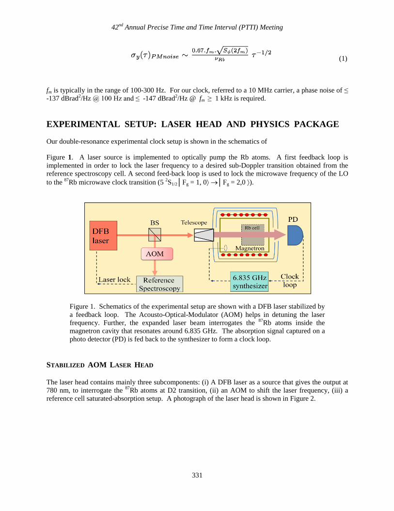
EXPERIMENTAL SETUP: LASER HEAD AND PHYSICS PACKAGE
Our double-resonance experimental clock setup is shown in the schematics of
Figure 1. A laser source is implemented to optically pump the Rb atoms. A first feedback loop is
implemented in order to lock the laser frequency to a desired sub-Doppler transition obtained from the
reference spectroscopy cell. A second feed-back loop is used to lock the microwave frequency of the LO
to the 87
Rb microwave clock transition (5 2S1/2│Fg = 1, 0 │Fg = 2,0 ).
Figure 1. Schematics of the experimental setup are shown with a DFB laser stabilized by
a feedback loop. The Acousto-Optical-Modulator (AOM) helps in detuning the laser
frequency. Further, the expanded laser beam interrogates the 87
Rb atoms inside the
magnetron cavity that resonates around 6.835 GHz. The absorption signal captured on a
photo detector (PD) is fed back to the synthesizer to form a clock loop.
STABILIZED AOM LASER HEAD
The laser head contains mainly three subcomponents: (i) A DFB laser as a source that gives the output at
780 nm, to interrogate the 87
Rb atoms at D2 transition, (ii) an AOM to shift the laser frequency, (iii) a
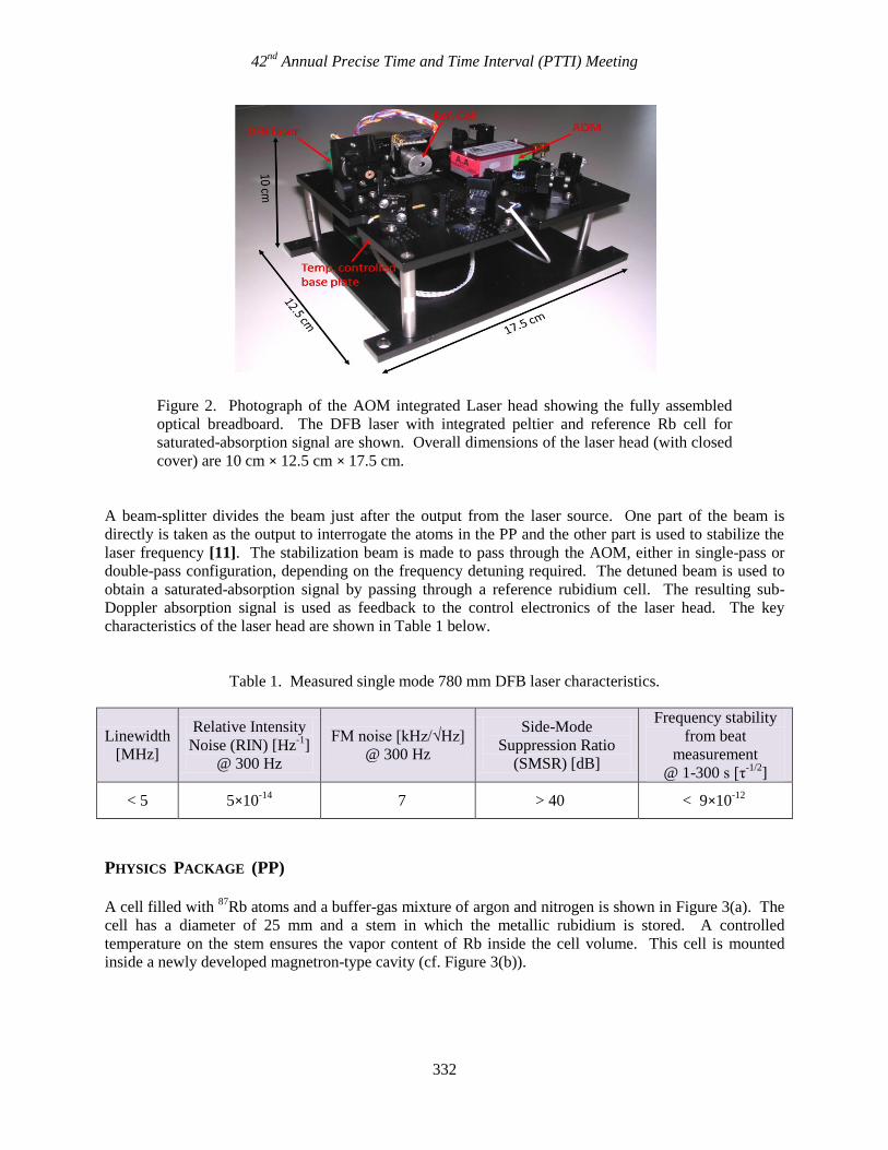
reference cell saturated-absorption setup. A photograph of the laser head is shown in Figure 2.
42nd
Annual Precise Time and Time Interval (PTTI) Meeting
332
Figure 2. Photograph of the AOM integrated Laser head showing the fully assembled
optical breadboard. The DFB laser with integrated peltier and reference Rb cell for
saturated-absorption signal are shown. Overall dimensions of the laser head (with closed
cover) are 10 cm × 12.5 cm × 17.5 cm.
A beam-splitter divides the beam just after the output from the laser source. One part of the beam is
directly is taken as the output to interrogate the atoms in the PP and the other part is used to stabilize the
laser frequency [11]. The stabilization beam is made to pass through the AOM, either in single-pass or
double-pass configuration, depending on the frequency detuning required. The detuned beam is used to
obtain a saturated-absorption signal by passing through a reference rubidium cell. The resulting sub-
Doppler absorption signal is used as feedback to the control electronics of the laser head. The key
characteristics of the laser head are shown in Table 1 below.
Table 1. Measured single mode 780 mm DFB laser characteristics.
Linewidth
[MHz]
Relative Intensity
Noise (RIN) [Hz-1
]
@ 300 Hz
FM noise [kHz/√Hz]
@ 300 Hz
Side-Mode
Suppression Ratio
(SMSR) [dB]
Frequency stability
from beat
measurement
@ 1-300 s [τ-1/2
]
< 5 5×10-14
7 > 40 < 9×10-12
PHYSICS PACKAGE (PP)
A cell filled with
87Rb atoms and a buffer-gas mixture of argon and nitrogen is shown in Figure 3(a). The
cell has a diameter of 25 mm and a stem in which the metallic rubidium is stored. A controlled
temperature on the stem ensures the vapor content of Rb inside the cell volume. This cell is mounted
inside a newly developed magnetron-type cavity (cf. Figure 3(b)).

42nd
Annual Precise Time and Time Interval (PTTI) Meeting
333
(a) (b)
Figure 3. (a) Buffer–gas cell (Ar/N2 mixture) with support cap. (b) Assembled & tuned
magnetron-type cavity with the cell. External diameter of the cavity is 40 mm.
Figure 4. Fully assembled PP shown. Two µ-metal magnetic shieldings cover the tuned
cavity.
The tuned cavity along with the cell is placed inside a holder, on which is wound a C-field coil for
splitting the degenerate ground-state hyperfine levels to Zeeman sub-levels, of which we are interested
only in the clock transition. This whole cavity assembly is covered by two µ-metal magnetic shields,
which have a measured longitudinal shielding factor of 3067. Two separate heaters are implemented: one
for cell volume and another one for the cell stem. The respective temperatures are sensed using NTC
resistors. A telescope assembly at the input end of the PP expands the laser beam to the cell dimension,
which is useful to interrogate the full cell volume for better signal contrast. At the rear end of the PP, a
focusing lens assembly focuses the light onto the photodetector. The fully assembled PP with above
explained design is shown in Figure 4.

42nd
Annual Precise Time and Time Interval (PTTI) Meeting
334
DOUBLE-RESONANCE (DR) AND LIGHT-SHIFT (LS)
DR SIGNAL
Double-Resonance (DR) involves two resonant electromagnetic fields: first, the optical-pumping resonant
field (D2 line, 5S1/2 5P3/2) provided by the laser, to pump all the atoms to one of the atomic ground
states; and second, a microwave field for driving the ground-state hyperfine transition at ~ 6.835 GHz,
which is applied to the atoms using the microwave cavity. A typical DR signal of the clock transition
from our clock setup is shown in Figure 5. Experimental parameters for the experiment were a cell
temperature around 50 °C, a laser power to the PP of 120 µW, and the laser frequency locked to the Fg =
2 to Fe = 2-3 cross-over resonance in the 87
Rb D2 line. A static magnetic C-field of 174 mG was applied
in the direction of the optical path, to split the Zeeman sub-levels and detect only the mF = 00, “clock
transition.”
Figure 5. Double-resonance signal.
The DR signal has a high contrast of 19% and a narrow linewidth of 548 Hz, resulting in an error signal
with an excellent discriminator slope of 1.5nA/Hz. Note that with this PP linewidths as low as 288 Hz
were measured, and even lower linewidths may be achieved when reducing further the optical and/or
microwave power. The estimated short-term stability based on the above DR signal is explained in detail
in Table 2.
LIGHT SHIFT, AND ITS REDUCTION BY DETUNING METHOD
The AC Stark shift, commonly known as Light Shift, of the electromagnetic field on the clock transition
is a basic limitation usually encountered in Rb clocks when in continuous wave (CW) operation. It arises
due to the light field driving virtual transitions in the atom, and in this sense is fundamentally related to
the Lamb shift which arises due to an atom’s interaction with the vacuum field [1]. The light shift can be
approximated as [3],
4.2
4.0
3.8
3.6Photo
curr
en
t [1
0-6
A]
2000150010005000-500-1000-1500-2000
Microwave detuning [Hz]
DR signal
Lorentzian fitFWHM = 548 HzContrast = 19 %Discriminator = 1.5 nA/Hz

42nd
Annual Precise Time and Time Interval (PTTI) Meeting
335
(2)
where L is the pump-laser frequency, is the width of the approximated Lorentzian signal centered at
the pumped optical atomic transition 0, and I is the intensity of the light. The intensity light-shift
coefficient slope can be written as
at a given laser frequency. The AOM integrated laser head
is used to minimize by controlled detuning of the laser to a frequency L ≈ 0 where is small [12].
Figure 6 shows both the undetuned LS coefficient (measured with the laser frequency directly stabilized
to the Rb saturated absorption lines) and the reduced value of light shift obtained by controlled detuning
of the laser frequency using the AOM.
By adjusting the laser frequency sent to the PP using the AOM, we obtain = 2.7 mHz/μW. This is
reduced by a factor of 37 compared to the lowest LS coefficient value of = 0.1 Hz/μW, which is
obtained without the AOM (i.e. with the pump-light frequency stabilized directly to one of the reference
saturated-absorption lines). By finely adjusting the detuning frequency, one can reduced the LS
coefficient value to be even less.
Figure 6. Light Shift without AOM for locking to different 87
Rb-D2 transitions, and
reduced LS effect with the AOM laser head are shown.
CLOCK LOOP AND MICROWAVE SYNTHESISER
The design was finalized based on the electronics of the Coherent Population Trapping maser [13] and of
the Pulsed Optically Pumped (POP) rubidium clock developed by IEN, Torino. In particular, the
synthesis chain scheme is similar to the one of the CPT maser, while the lock-in scheme is taken from the
POP clock.
The Local Oscillator (LO) interrogates the atoms by means of the synthesis chain. The signal coming
from the photodiode is amplified by the trans-impedance amplifier (TI), acquired by an analog-to-digital
8x10⁻⁹
7
6
5
4
3
2
1
0
-1
-2
Rela
tive Insta
bili
ty
140120100806040200-20
Laser Power [W]
No AOM detuning Fg=2 to Fe=3
Fg=2 to Fe=23CO
Fg=2 to Fe=13CO
= 2.7 mHz/W
With AOM detuning (Single pass)
= 0.1 Hz/W

42nd
Annual Precise Time and Time Interval (PTTI) Meeting
336
converter (ADC) and then processed by a programmable logic device (PLD) that implements the lock-in
and the integrator blocks. The loop gain, and consequently the loop bandwidth, can be adjusted by
changing a multiplicative constant. All the parameters involved are set via a computer user interface.
With respect to the CPT Maser, the signal-to-noise ratio at 1 s of the ADC is improved from 100 dB to
120 dB by increasing the sampling frequency (from 100 kHz to 10 MHz) and the noise bandwidth (from
10 kHz to 1 MHz). The lock-in scheme allows a first-order rejection of the electronic offset, drift, and
flicker noise, leading a more stable long-term behavior. The integrator, also digitally implemented, does
not introduce any offset and any other kind of long-term fluctuations. The 16-bit digital-to-analog
converter (DAC) allows a frequency resolution better than 10-12
and an electronic tuning of the OCXO of
about 10-7
.
Figure 7. Block diagram of LO electronics.
The first frequency multiplication stages are designed to multiply the 10 MHz signal up to 180 MHz.
This frequency is suitable for direct multiplication in the microwave range by a Step-Recovery Diode
(SRD) that produces a continuous comb of spectral components separated by 180 MHz. The required
components at 7.02 GHz are filtered out by coaxial filters and are cleaned by residual nearby components
of the multiplication process by using a Yttrium-Iron-Garnet oscillator (YIG). As shown in Figure 8, the
7.02 GHz signal is mixed with the 185.3 MHz one inside the YIG Phase Lock Loop (PLL) in order to
refer the YIG to the quartz oscillator. The 183.7 MHz is obtained as a sum of 180 MHz and 5.3 MHz
coming from a Direct Digital Synthesizer (DDS), which realizes the fine tuning of the synthesis chain.
Moreover, the DDS is also used for phase/frequency modulation purposes.
Rb cell
µW cavity
TI
10 MHz
Synthesis
Chain
6.834 GHz
Control
signal
Error
signal
Clock Output
67 Hz
Mod Demod
PC
Gain
INTEGR.A
DC
1
State
Machine
Gain
Working parameters
DA
C
PLD
Laser system
LO
Rb cell
µW cavity
Rb cell
µW cavity
TITI
10 MHz
Synthesis
Chain
6.834 GHz
Control
signal
Error
signal
Clock Output
67 Hz
Mod Demod
PC
Gain
INTEGR.A
DC
AD
C
1
State
Machine
Gain
Working parameters
DA
CD
AC
PLD
Laser system
LO

42nd
Annual Precise Time and Time Interval (PTTI) Meeting
337
Figure 8. The block diagram of synthesis chain.
A picture of LO electronics with the loop electronics and synthesis chain is shown in Figure 9 below.
Figure 9. Picture of LO electronics.
Two identical synthesis chains have been compared using the homodyne technique and the result has
been referred to a 10 MHz carrier. It has a flicker level of –124 dB rad2/Hz and a noise floor of
–154 dB rad2/Hz.
Frequency
Multiplication
and
Signal
Distribution
180 MHz
180 MHz
60 MHz
10 MHz
OCXO
Output
x 39
Microwave
Output
SRD7.02 GHz
filter YIG
6834.7 MHz
185.3 MHz
5.3 MHz
180 MHz
Q
DDS
I
Digital modulation60 MHz
Distribution
Amplifier
to micro-
controller
10 MHz
dtFrequency
Multiplication
and
Signal
Distribution
180 MHz
180 MHz
60 MHz
10 MHz
OCXOOCXO
Output
x 39
Microwave
Output
SRD7.02 GHz
filter YIG
6834.7 MHz
185.3 MHz
5.3 MHz
180 MHz
Q
DDS
I
Digital modulation60 MHz
Distribution
Amplifier
to micro-
controller
10 MHz
dt dt
42nd
Annual Precise Time and Time Interval (PTTI) Meeting
338
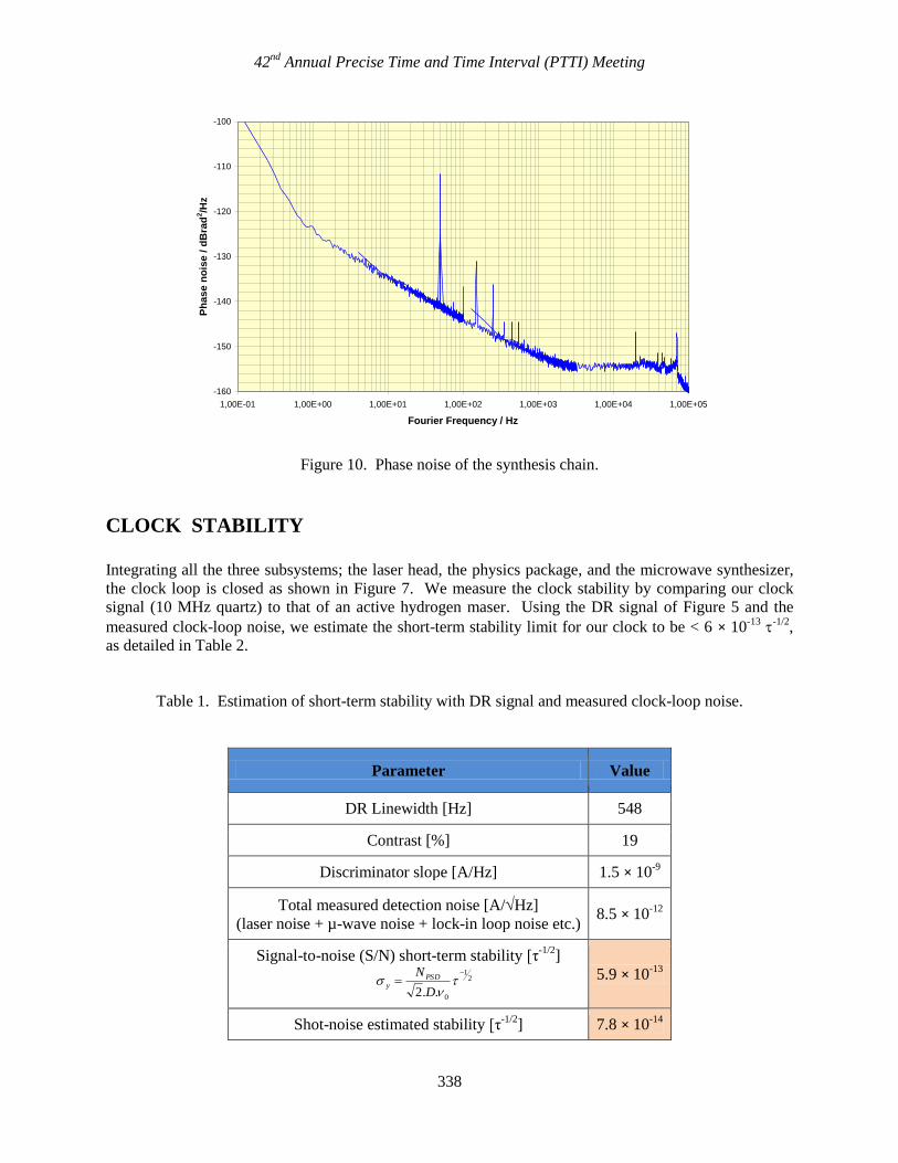
Figure 10. Phase noise of the synthesis chain.
CLOCK STABILITY
Integrating all the three subsystems; the laser head, the physics package, and the microwave synthesizer,
the clock loop is closed as shown in Figure 7. We measure the clock stability by comparing our clock
signal (10 MHz quartz) to that of an active hydrogen maser. Using the DR signal of Figure 5 and the
measured clock-loop noise, we estimate the short-term stability limit for our clock to be < 6 × 10-13
-1/2
,
as detailed in Table 2.
Table 1. Estimation of short-term stability with DR signal and measured clock-loop noise.
Parameter Value
DR Linewidth [Hz] 548
Contrast [%] 19
Discriminator slope [A/Hz] 1.5 × 10⁻⁹
Total measured detection noise [A/Hz]
(laser noise + µ-wave noise + lock-in loop noise etc.) 8.5 × 10
-12
Signal-to-noise (S/N) short-term stability [τ-1/2
]
5.9 × 10⁻¹³
Shot-noise estimated stability [τ-1/2
] 7.8 × 10⁻¹⁴
-160
-150
-140
-130
-120
-110
-100
1,00E-01 1,00E+00 1,00E+01 1,00E+02 1,00E+03 1,00E+04 1,00E+05
Fourier Frequency / Hz
Ph
ase n
ois
e /
dB
rad
2/H
z
21
0..2
D
NPSDy
42nd
Annual Precise Time and Time Interval (PTTI) Meeting
339
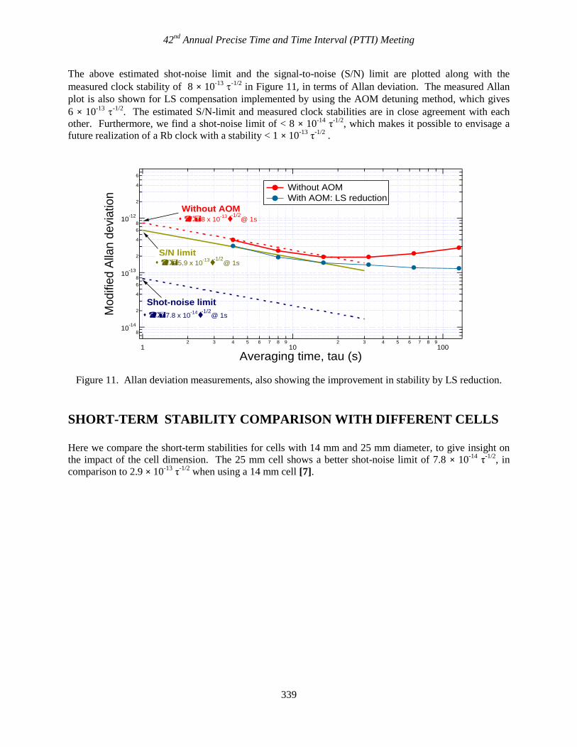
The above estimated shot-noise limit and the signal-to-noise (S/N) limit are plotted along with the
measured clock stability of 8 × 10-13
-1/2
in Figure 11, in terms of Allan deviation. The measured Allan
plot is also shown for LS compensation implemented by using the AOM detuning method, which gives
6 × 10-13
-1/2
. The estimated S/N-limit and measured clock stabilities are in close agreement with each
other. Furthermore, we find a shot-noise limit of < 8 × 10-14
τ-1/2
, which makes it possible to envisage a
future realization of a Rb clock with a stability < 1 × 10-13
τ-1/2
.
Figure 11. Allan deviation measurements, also showing the improvement in stability by LS reduction.
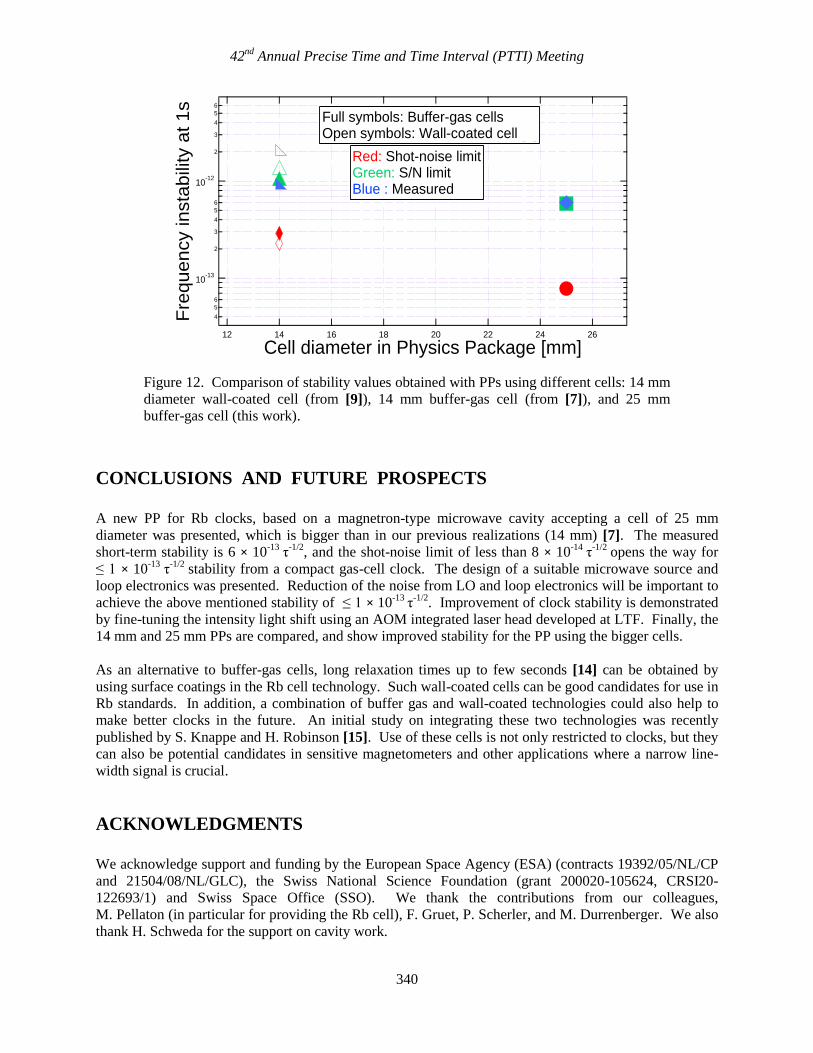
SHORT-TERM STABILITY COMPARISON WITH DIFFERENT CELLS
Here we compare the short-term stabilities for cells with 14 mm and 25 mm diameter, to give insight on
the impact of the cell dimension. The 25 mm cell shows a better shot-noise limit of 7.8 × 10⁻¹⁴
τ-1/2
, in
comparison to 2.9 × 10⁻¹³
τ-1/2
when using a 14 mm cell [7].
810
-14
2
4
6
810
-13
2
4
6
810
-12
2
4
6
Mo
difie
d A
llan
de
via
tio
n
12 3 4 5 6 7 8 9
102 3 4 5 6 7 8 9
100
Averaging time, tau (s)
S/N limit
Shot-noise limit
Without AOM
Without AOM
With AOM: LS reduction
8 x 10-13
-1/2@ 1s
5.9 x 10⁻¹³
-1/2@ 1s
7.8 x 10⁻¹⁴
-1/2@ 1s
42nd
Annual Precise Time and Time Interval (PTTI) Meeting
340
Figure 12. Comparison of stability values obtained with PPs using different cells: 14 mm
diameter wall-coated cell (from [9]), 14 mm buffer-gas cell (from [7]), and 25 mm
buffer-gas cell (this work).
CONCLUSIONS AND FUTURE PROSPECTS
A new PP for Rb clocks, based on a magnetron-type microwave cavity accepting a cell of 25 mm
diameter was presented, which is bigger than in our previous realizations (14 mm) [7]. The measured
short-term stability is 6 × 10-13
τ-1/2
, and the shot-noise limit of less than 8 × 10-14
τ-1/2
opens the way for
≤ 1 × 10-13
τ-1/2
stability from a compact gas-cell clock. The design of a suitable microwave source and
loop electronics was presented. Reduction of the noise from LO and loop electronics will be important to
achieve the above mentioned stability of ≤ 1 × 10-13
τ-1/2
. Improvement of clock stability is demonstrated
by fine-tuning the intensity light shift using an AOM integrated laser head developed at LTF. Finally, the
14 mm and 25 mm PPs are compared, and show improved stability for the PP using the bigger cells.
As an alternative to buffer-gas cells, long relaxation times up to few seconds [14] can be obtained by
using surface coatings in the Rb cell technology. Such wall-coated cells can be good candidates for use in
Rb standards. In addition, a combination of buffer gas and wall-coated technologies could also help to
make better clocks in the future. An initial study on integrating these two technologies was recently
published by S. Knappe and H. Robinson [15]. Use of these cells is not only restricted to clocks, but they
can also be potential candidates in sensitive magnetometers and other applications where a narrow line-
width signal is crucial.
ACKNOWLEDGMENTS
We acknowledge support and funding by the European Space Agency (ESA) (contracts 19392/05/NL/CP
and 21504/08/NL/GLC), the Swiss National Science Foundation (grant 200020-105624, CRSI20-
122693/1) and Swiss Space Office (SSO). We thank the contributions from our colleagues,
M. Pellaton (in particular for providing the Rb cell), F. Gruet, P. Scherler, and M. Durrenberger. We also
thank H. Schweda for the support on cavity work.
4
5
6
10-13
2
3
4
5
6
10-12
2
3
4
5
6
Fre
quen
cy insta
bili
ty a
t 1s
2624222018161412
Cell diameter in Physics Package [mm]
Full symbols: Buffer-gas cells [6]Open symbols: Wall-coated cell [3]
Red: Shot-noise limitGreen: S/N limitBlue : Measured
42nd
Annual Precise Time and Time Interval (PTTI) Meeting
341
REFERENCES
[1] J. Camparo, 2007, “The rubidium atomic clock and basic research,” Physics Today, 33-39.
[2] J. Vanier and C. Mandache, 2007, “The passive optically pumped Rb frequency standard: the laser
approach,” Applied Physics B: Lasers and Optics, 87, 565-593.
[3] C. Affolderbach, F. Droz, and G. Mileti, 2006, “Experimental demonstration of a compact and high-
performance laser-pumped rubidium gas cell atomic frequency standard,” in IEEE Transactions on
Instrumentation and Measurement, IM-55, 429-435.
[4] F. Gruet, D. Miletic, C. Affolderbach, G. Mileti, V. Vilokkinen, and P. Melanen, 2009, “Spectral
characterization of aged and non-aged 894 nm DFB for their application in Cs atomic clocks,” in
Proceedings of the International Symposium on Reliability of Optoelectronics for Space (ISROS), Jointly
with Radiation Effects on Optoelectronics (OPTORAD), 11-15 May 2009, Cagliari, Italy, pp. 295-299.
[5] G. Mileti, J. Deng, F. L. Walls, D. A. Jennings, and R. E. Drullinger, 1998, “Laser-pumped rubidium
frequency standards: new analysis and progress,” IEEE Journal of Quantum Electronics, 34, 233-237.
[6] H. Schweda, G. Busca, and P. Rochat, 1995, “Atomic Frequency Standard,” United States Patent
no. 5,387,881.
[7] C. Affolderbach, R. Matthey, F. Gruet, T. Bandi, and G. Mileti, EFTF, 2010, “Realisation of a
compact laser-pumped Rubidium frequency standard with < 1 x 10-12
stability at 1 second,” in
Proceedings of the 24th European Frequency and Time Forum (EFTF), 13-16 April 2010, Noordwijk, The
Netherlands.
[8] F. Gruet, T. Bandi, M. Pellaton, C. Affolderbach, R. Matthey and G. Mileti, 2010, “Compact
stabilized laser heads for frequency standards and spectroscopy,” in Proceedings of Optical Clocks: A
New Frontier in High Accuracy Metrology, 1-3 December 2010, Torino, Italy (in press).
[9] T. Bandi, C. Affolderbach and G. Mileti, 2010, “Study of Rb 0-0 hyperfine double-resonance
transition in a wall-coated cell,” in Proceedings of the 24th European Frequency and Time and Forum
(EFTF), 13-16 April 2010, Noordwijk, The Netherlands.
[10] J. Q. Deng, G. Mileti, R. E. Drullinger, D. A. Jennings, and F. L. Walls, 1999, “Noise considerations
for locking to the center of a lorentzian line,” Physical Review, A 59, 773-777.
[11] C. Affolderbach and G. Mileti, 2005, “A compact laser head with high-frequency stability for Rb
atomic clocks and optical instrumentation,” Review of Scientific Instruments, 76, 073108.
[12] G. Mileti, J. Q. Deng, F. L. Walls, J. P. Lowe, and R. E. Drullinger, 1996, “Recent Progress in laser-
pumped gas-cell frequency standards,” in Proceedings of the 1996 IEEE International Frequency Control
Symposium, 5 -7 June 1996, Honolulu, Hawaii, USA (IEEE 96CH35935), pp.1066-1072.
[13] C. E. Calosso, F. Levi, E. K. Bertacco, A. Godone, and S. Micalizio, 2005, “Low-Noise Electronic
Design for the 87RbCoherent Population Trapping Maser,” IEEE Transactions on Ultrasonics,
Ferroelectrics, and Frequency Control, UFFC-52, 1923-1930.

42nd
Annual Precise Time and Time Interval (PTTI) Meeting
342
[14] M. V. Balabas, T. Karaulanov, M. P. Ledbetter, and D. Budker, 2010, “Polarized alkali-metal
vapour with minute-long transverse spin-relaxation time,” Physical Review Letters, 105, 070801.
[15] S. Knappe and H. G. Robinson, 2010, “Double-resonance lineshapes in a cell with wall coating and
buffer gas,” New Journal of Physics, 12, 065021.


![Compact Triangular Slot Antenna with Improved … · Compact Triangular Slot Antenna with Improved ... .Zeland IE3D [18] ... A. Balanis, “Advanced Engineering Electromagnetics”,](https://img.pdfslide.net/doc/110x75/5acbed9e7f8b9aa1518bb8a7/compact-triangular-slot-antenna-with-improved-triangular-slot-antenna-with-improved.jpg)


![Magnetic Contactors & Thermal Overload Relays...Structure of Thermal Overload Relay. Overview . 1] Performance . Compact size & Easy connection . Improved Arc Protection from sealed](https://img.pdfslide.net/doc/110x75/5e7c728c896df074b5229847/magnetic-contactors-thermal-overload-relays-structure-of-thermal-overload.jpg)