Embed Size (px)
Citation preview
STUDIES ON CODING TECHNIQUES AND IT’S APPLICATION TO OTDR
A Project Report
Submitted in partial fulfilment of the requirements for the award of the
degree
Of
BACHELOR OF TECHNOLOGY
IN
ELECTRONICS AND COMMUNICATION ENGINEERING
By
V Jaikishen (10509011)
Sudharani Kindo (10509008)
Under the guidance of
Prof. P.K. Sahu
Department of Electronics & Communication Engineering
National Institute of Technology
Rourkela,769008 (2008-2009)
ii
STUDIES ON CODING TECHNIQUES AND IT’S APPLICATION TO OTDR
A Project Report
Submitted in partial fulfilment of the requirements for the award of the
degree
Of
BACHELOR OF TECHNOLOGY
IN
ELECTRONICS AND COMMUNICATION ENGINEERING
By
V Jaikishen (10509011)
Sudharani Kindo (10509008)
Under the guidance of
Prof. P.K. Sahu
Department of Electronics & Communication Engineering
National Institute of Technology
Rourkela, 769008 (2008-2009)
iii
National Institute of Technology Rourkela
CERTIFICATE
This is to certify that the thesis entitled, “Studies on coding techniques and its application to
OTDR” submitted by V Jaikishen and Sudharani Kindo in partial fulfillments for the
requirements for the award of Bachelor of Technology Degree in Electronics &
Communication Engineering at National Institute of Technology, Rourkela (Deemed
University) is an authentic work carried out by him under my supervision and guidance.
To the best of my knowledge, the matter embodied in the thesis has not been submitted to any
other University / Institute for the award of any Degree or Diploma.
Date:
Prof. P. K. SAHU
Dept. of Electronics & Communication Engg.
National Institute of Technology
Rourkela - 769008
iv
ACKNOWLEDGEMENT
We place on record and warmly acknowledge the continuous encouragement, invaluable
supervision, timely suggestions and inspired guidance offered by our guide Prof. P.K.Sahu,
Professor, Department of Electronics and Communication Engineering, National Institute of
Technology, Rourkela, in bringing this report to a successful completion.
We are grateful to Prof. S.K.Patra, Head of the Department of Electronics and
communication Engineering, for permitting us to make use of the facilities available in the
department to carry out the project successfully. Last but not the least we express our sincere
thanks to all of our friends who have patiently extended all sorts of help for accomplishing
this undertaking.
We are particularly grateful to Prof S.K. Varshney, Professor, Department of Electrical and
Electronics Communication Engineering, Indian Institute of Technology, Kharagpur and Mr.
Utpal Patra, in charge of Optics Lab at the same for permitting us to use the resources
available there to carry out the project successfully.
Finally we extend our gratefulness to one and all who are directly or indirectly involved in
the successful completion of this project work.
V Jaikishen (10509011)
Sudharani Kindo (10509008)
v
Abstract:
In the following thesis, we will be discussing the different aspects and
parameters involving Optical Time Domain Reflectometer (OTDR) as well as
different aspects of unipolar coding techniques. The purpose of this thesis is to
fully understand the methods by which unipolar codes like the Golay and
Simplex codes are created from Hadamard matrices and to understand its
application in Optical Time Domain Reflectometry. Furthermore, this thesis also
delves into the region of performance enhancement of Optical Time Domain
Reflectometer by means of implementation of these coding techniques.
vi
Contents
List of figures
List of tables
Abstract
Chapter 1: Basics of an Optical Time Domain Reflectometer. .... 1
1.1 Introduction to OTDR .... 2
1.2 Parameters of OTDR .... 3
1.2.1 Reflection .... 3
1.2.2 Dead zone .... 4
1.2.3 Dynamic range .... 7
1.2.4 Pulse width .... 8
1.2.5 Sampling resolution and sampling points .... 9
1.3 Conclusion .... 11
Chapter 2: Introduction and mathematical analysis of coding
techniques .... 12
2.1 Introduction to coding techniques .... 13
2.2 SNR of conventional OTDR .... 14
2.3 Different Codes implemented in OTDR .... 15
2.3.1 Golay Codes .... 15
2.3.2 Bi-Orthogonal Codes .... 18
2.3.3 Simplex Codes .... 23
2.3.4 CCPONS .... 26
2.4 Conclusion .... 29
Chapter 3: Experiments using conventional OTDR .... 30
3.1 Experiments on OTDR .... 31
3.1.1 Aim of the experiment .... 31
3.1.2 Equipment used .... 31
3.1.3 Experimental setup .... 31
3.1.4 OTDR specifications .... 31

vii
3.1.5 Observations .... 32
3.2 Conclusion .... 35
Chapter 4: Results and Future prospects .... 36
4.1 Results .... 37
4.2 Advantages of coding techniques over conventional OTDR .... 38
4.3 Future scope and prospects .... 38
4.4 Conclusion .... 39
References .... 40
viii
List of Figures:
Fig. 1.1: A typical OTDR trace screen. .... 2
Fig. 1.2: Schematic representation of Rayleigh backscattering. .... 3
Fig. 1.3: The detected trace responses in cases of connections and open ends. .... 4
Fig. 1.4: Event dead zone in case of merged event. .... 5
Fig. 1.5: A standard event dead zone as seen in OTDR trace. .... 5
Fig. 1.6: 1st case of attenuation dead zone. .... 6
Fig. 1.7: 2nd
case of attenuation dead zone. .... 7
Fig. 1.8: Representation of input energy for different cases of pulses. .... 8
Fig. 1.9: Fault detection in high resolution cases. .... 10
Fig. 1.10: Fault detection in low resolution cases. .... 10
Fig. 2.1: Pulse generation used in bi-orthogonal codes. .... 21
Fig. 2.2: Code gain comparison of bi-orthogonal code with Golay code. .... 23
Fig. 2.3: Coding gain in Case of Simplex Codes. .... 26
Fig. 2.4: Code gain variation of CCPONS. .... 28
Fig. 2.5: Comparison of Code gain for different code length of different codes. .... 28
Fig. 3.1: Experimental setup used to perform the experiment. .... 31
Fig. 3.2: OTDR trace of SMF at 1310 nm wavelength .... 32
Fig. 3.3: OTDR trace of SMF at 1550 nm wavelength .... 33
Fig. 3.4: OTDR trace of MMF at 1310 nm wavelength .... 34
Fig. 3.5: OTDR trace of MMF at 1550 nm wavelength .... 35
Fig. 4.1: The excessive equipment required to integrate coding into an OTDR. .... 39

ix
List of tables:
Table 2.1: Some examples of Golay code .... 16
Table 4.1 Coding gain and PAPRs of code concerned .... 37
CHAPTER 1
BASICS OF AN OPTICAL TIME DOMAIN
REFLECTOMETER.
2
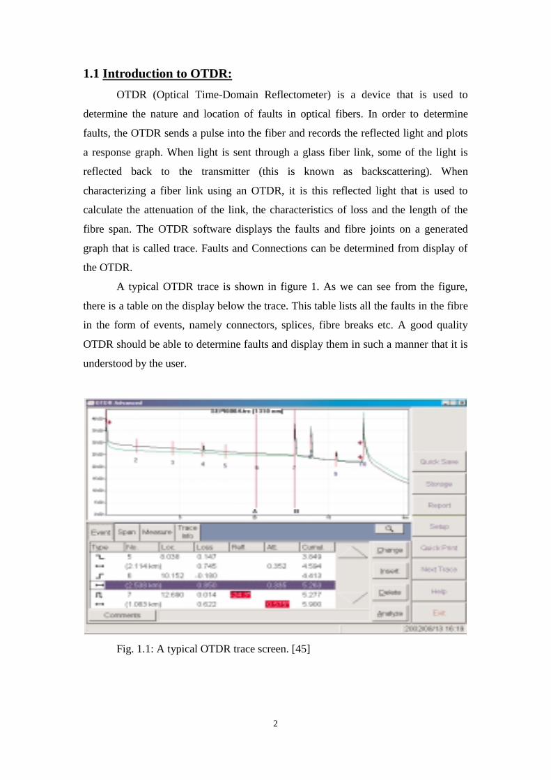
1.1 Introduction to OTDR:
OTDR (Optical Time-Domain Reflectometer) is a device that is used to
determine the nature and location of faults in optical fibers. In order to determine
faults, the OTDR sends a pulse into the fiber and records the reflected light and plots
a response graph. When light is sent through a glass fiber link, some of the light is
reflected back to the transmitter (this is known as backscattering). When
characterizing a fiber link using an OTDR, it is this reflected light that is used to
calculate the attenuation of the link, the characteristics of loss and the length of the
fibre span. The OTDR software displays the faults and fibre joints on a generated
graph that is called trace. Faults and Connections can be determined from display of
the OTDR.
A typical OTDR trace is shown in figure 1. As we can see from the figure,
there is a table on the display below the trace. This table lists all the faults in the fibre
in the form of events, namely connectors, splices, fibre breaks etc. A good quality
OTDR should be able to determine faults and display them in such a manner that it is
understood by the user.
Fig. 1.1: A typical OTDR trace screen. [45]

11
details so that their design can perform even under difficult circumstances. Next we
will see the different coding techniques used in OTDR systems.
1.3 Conclusion:
In this chapter we have seen the different aspects of OTDR and what are the different
criteria to be considered while designing or selection of one for research or for
practical purposes.
HAPTER 2
INTRODUCTION AND MATHEMATICAL ANALYSIS
OF DIFFERENT CODING TECHNIQUES
13
2.1 Introduction to coding:
Coding tackles the two major parameters of an OTDR, namely dead zone and pulse
width. As we have seen in the pulse width section, we need more energy in the signal
that the OTDR sends in order to detect faults in extremely long fibers. By
incorporating a code of a length of, say 64 bits, we are in fact sending that many
pulses into the fiber and hence input that much energy into the fiber and hence we can
improve the SNR of the OTDR as increasing signal power for the same level of noise
results in larger SNR. Also the dead zone problem is also accounted for as in coding
the no of pulses are increased and not the pulse width in itself.
OTDR is an important diagnostic tool for the testing of fiber optic transmission
system. At present time when optical fiber technology is widely applied not only in
building up of optical fiber transmission systems but also in other fields like sensors
with distributed parameters ―Optical Time-Domain Reflectometry‖ (OTDR) plays an
important role. The basic idea of the conventional OTDR consists in launching a
rather short and high power optical impulse into the tested fiber and the consequent
detection of the Rayleigh back-scattered or Fresnel reflected light at the input end of
the fiber. The measured signal is very weak – typically 40-60 dB under the level of
the launched optical power. In OTDR there is also a well-known trade-off between
the Signal-Noise Ratio (SNR) and the spatial resolution. Increasing the pulse width of
the probe pulse improves the signal-to-noise ratio (SNR) of the detected signal and
accordingly improves the dynamic range but degrades the spatial resolution of the
OTDR. To overcome this tradeoff between the SNR and the spatial resolution, the use
of correlation techniques—commonly used in wireless radars—have been suggested,
e.g., employing periodic pseudorandom bit sequences (PRBSs). Still, with the
problem resulting from the periodic features of PRBS, this approach was found to be
unsuitable for the practical applications. Overcoming the limitations of PRBS-coded
OTDR, the complementary correlation OTDR (cc-OTDR) based on the Golay codes
was suggested. Following the cc-OTDR, an OTDR based on the simplex codes (scs),
Biorthogonal codes, correlated Prometheus orthonormal sequence was then proposed,
predicting better SNR performances (over the Golay-code cc-OTDR) without the
penalty in the spatial resolution. Still, with the analysis based on simple analogy—
compared to that of optical spectrometry the scope of the work was limited to a
conjecture on the expected amount of coding gain (SNR increase over conventional
29
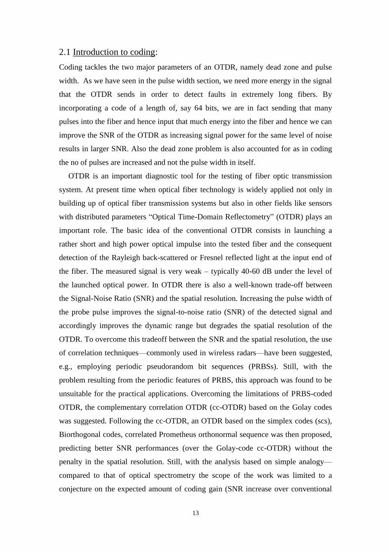
Figure below shows us the code gain obtained while using CCPONS
Fig. 2.4: Code gain variation of CCPONS.[5]
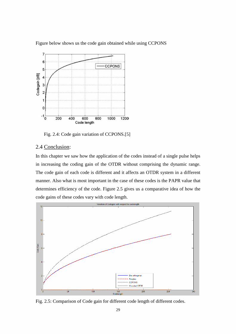
2.4 Conclusion:
In this chapter we saw how the application of the codes instead of a single pulse helps
in increasing the coding gain of the OTDR without comprising the dynamic range.
The code gain of each code is different and it affects an OTDR system in a different
manner. Also what is most important in the case of these codes is the PAPR value that
determines efficiency of the code. Figure 2.5 gives us a comparative idea of how the
code gains of these codes vary with code length.
Fig. 2.5: Comparison of Code gain for different code length of different codes.
CHAPTER 3
EXPERIMENTS USING CONVENTIONAL OTDR
31
3.1 Experimental Studies on an OTDR:
The experimental studies were performed on an Agilent 6000 series OTDR at IIT
Kharagpur. The details are as follows.
3.1.1 Objective of the experiment:
To understand the workings of an OTDR and to take real-time measurements from
single mode and multi mode fibres using the OTDR
3.1.2 Equipment:
1. Agilent E6003A mini-OTDR
2. Optical fibre, singlemode fibre of 500 metres length and two multimode fibres of
lengths 1000 metres and 500 metres.
3. Mechanical connectors
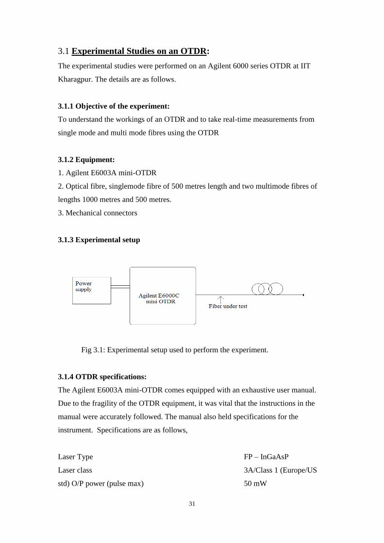
3.1.3 Experimental setup
Fig 3.1: Experimental setup used to perform the experiment.
3.1.4 OTDR specifications:
The Agilent E6003A mini-OTDR comes equipped with an exhaustive user manual.
Due to the fragility of the OTDR equipment, it was vital that the instructions in the
manual were accurately followed. The manual also held specifications for the
instrument. Specifications are as follows,
Laser Type FP – InGaAsP
Laser class 3A/Class 1 (Europe/US
std) O/P power (pulse max) 50 mW
35
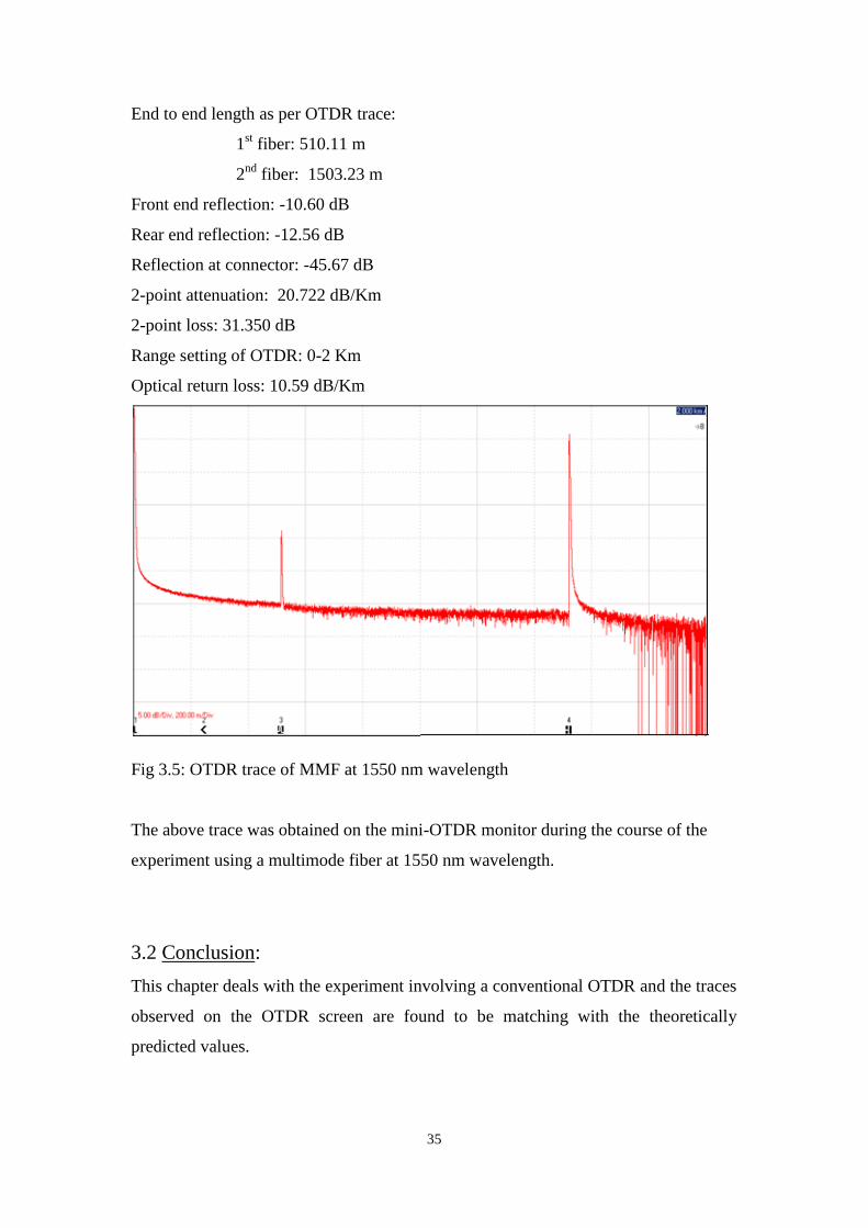
End to end length as per OTDR trace:
1st fiber: 510.11 m
2nd
fiber: 1503.23 m
Front end reflection: -10.60 dB
Rear end reflection: -12.56 dB
Reflection at connector: -45.67 dB
2-point attenuation: 20.722 dB/Km
2-point loss: 31.350 dB
Range setting of OTDR: 0-2 Km
Optical return loss: 10.59 dB/Km
Fig 3.5: OTDR trace of MMF at 1550 nm wavelength
The above trace was obtained on the mini-OTDR monitor during the course of the
experiment using a multimode fiber at 1550 nm wavelength.
3.2 Conclusion:
This chapter deals with the experiment involving a conventional OTDR and the traces
observed on the OTDR screen are found to be matching with the theoretically
predicted values.

CHAPTER 4
RESULTS AND FUTURE SCOPE OF WORK
37
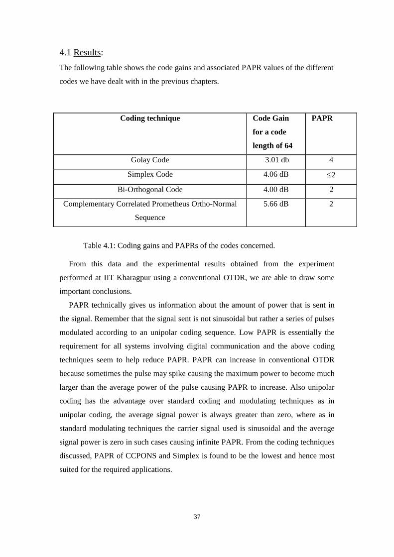
4.1 Results:
The following table shows the code gains and associated PAPR values of the different
codes we have dealt with in the previous chapters.
Table 4.1: Coding gains and PAPRs of the codes concerned.
From this data and the experimental results obtained from the experiment
performed at IIT Kharagpur using a conventional OTDR, we are able to draw some
important conclusions.
PAPR technically gives us information about the amount of power that is sent in
the signal. Remember that the signal sent is not sinusoidal but rather a series of pulses
modulated according to an unipolar coding sequence. Low PAPR is essentially the
requirement for all systems involving digital communication and the above coding
techniques seem to help reduce PAPR. PAPR can increase in conventional OTDR
because sometimes the pulse may spike causing the maximum power to become much
larger than the average power of the pulse causing PAPR to increase. Also unipolar
coding has the advantage over standard coding and modulating techniques as in
unipolar coding, the average signal power is always greater than zero, where as in
standard modulating techniques the carrier signal used is sinusoidal and the average
signal power is zero in such cases causing infinite PAPR. From the coding techniques
discussed, PAPR of CCPONS and Simplex is found to be the lowest and hence most
suited for the required applications.
Coding technique Code Gain
for a code
length of 64
PAPR
Golay Code 3.01 db 4
Simplex Code 4.06 dB 2
Bi-Orthogonal Code 4.00 dB 2
Complementary Correlated Prometheus Ortho-Normal
Sequence
5.66 dB 2
38
4.2 Advantages of Coding over Conventional OTDR:
The basic principle in OTDR is to send a small signal through an optical fibre and
observe the reflected light. The intensity of the reflected light depends upon many
parameters like nature of the fibre, wavelength of light etc. One of the parameters
influencing this is the power of the input signal. Larger the input power, larger will be
the distance it covers within the fibre. The easiest way of increasing input power
would be to send n number of pulses one after the other. But this method has a
drawback because u cannot just send pulses like that as it will result in the receiver
getting saturated very quickly and it will result in a permanent dead zone that renders
the analysis ineffective.
This is where the concept of coding shows its advantage. By using unipolar coding
techniques, one is able to send a large amount of input power by using less number of
pulses. This way we are able to avoid the scenario of receiver getting saturated.
The other advantages of coding techniques over conventional OTDR include better
dynamic range and greater spatial resolution with a definite amount of noise present
in the system.
4.3 Future scope and prospects:
Throughout this thesis, we have been discussing the different parameters of an OTDR
and how external factors can affect them. In the different chapters we have seen how
coding is one of the ways to improve the SNR of an OTDR system and also through
different coding methods a better dynamic range and spatial resolution trade off can
be achieved.
The experiment performed using the Agilent Mini-OTDR at IIT Kharagpur helped
us understand the tracing phenomenon of the OTDR. It is crucial to understand the
fact each OTDR manufacturer chooses the different characteristics to be included in
their OTDR design. The feature not so commonly found though is the ability to
integrate a PC based OTDR into a single kit. Most practical experiments involving the
testing of coding revolves around a circuit that is similar to the one shown below.
39
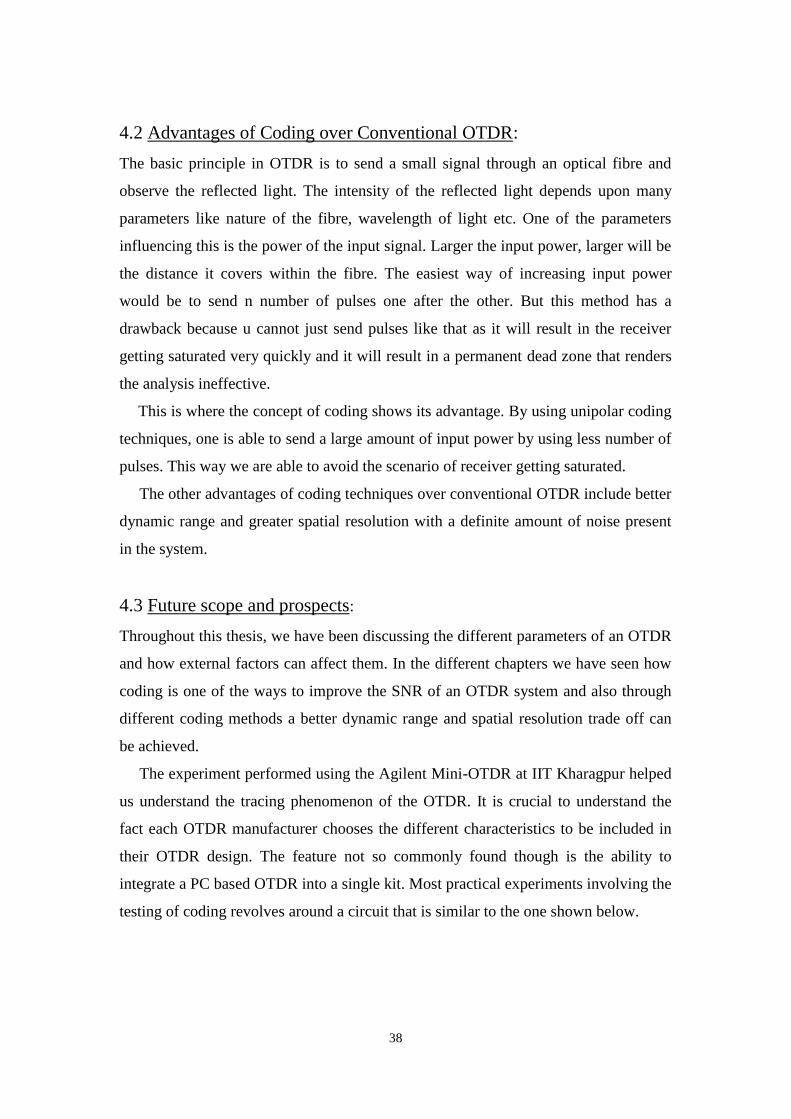
Fig 4.1: The excessive equipment required to integrate coding into an OTDR.[5]
This figure is the experimental setup that was used to implement CCPONS code in
an OTDR. The entire circuitry except for the waveform generator (WFG) and the
modulator (MZM) is integrated into the current available models of OTDR. The
waveform generator and the modulator are the two components of this setup that
allow the CCPONS code to be integrated in the testing mechanism.
Throughout the years, the process of implementing various codes and sequences in
an OTDR has involved extensive setups like the ones above. But the results of the
implementing these codes has been obvious each time a new code is developed. The
results of the various experiments performed can be used to facilitate research into
design of new OTDR machines which implement these coding techniques in their
probing mechanisms. This will result in better fault analysis and the ability of the
OTDR to analyze extremely long fibres.
The different experiments and its results that have been studied in this thesis can be
used in future to design highly efficient OTDR systems that will be able to provide a
better SNR, lower PAPR and in affect improve the dynamic range of the OTDR to a
far greater degree.
4.4 Conclusion:
From this chapter it can be concluded that OTDR systems implementing various
unipolar codes out perform a conventional OTDR system and by implementation of
such codes, PAPR of the signal can be reduced that helps to add to the efficiency of
the OTDR system
40
REFERENCES:
[1] Jozef Jasenek, Iozefa Cervenova, Marek Hlavac , ―The enhancement of signal to noise in OTDR by
the use of probe signal coding.‖ IEEE Bratislava, May 2001, vol. 3, pp. 47–51
[2] Duckey Lee, Hosung Yoon, Na Young Kim, and Namkyoo Park, ―SNR Improvement of a Non-
Coherent OTDR Using Biorthogonal Codes and Moore-Penrose Generalized Inverses.‖ ECOC
2004 Proceedings-Vol.3 Paper We4.P.156
[3] Duckey Lee,Hosung Yoon,Pilhan Kim,Jonghan Park,and Namkyoo Park, ―Optimization of SNR
Improvement in the Noncoherent OTDR Based on Simplex Codes.‖ Journal of Lightwave
technology,Vol 24,No.1,January 2006
[4] Michael D.Jones, ―Using simplex code to improve OTDR sensitivity.‖ IEEE phototonics
technology letters,VOL 15,No.7,July 1993
[5] P.K.Sahu,S.C.Gowre,S.Mahapatra,‖Optical time-domain reflectometer performance performance
improvement using complementary correlated Prometheus Orthonormal Sequence‖IET
Optoelectronics 2007
[6] M.Nazarathy and group, ―Real time long range complementary correlation optical time domain
reflectometer‖, J. Light Wave technol., Vol. 7, pp. 24-38, Jan. 1989
[7] BETHEA C.G., LEVINE B.F., CAVA S., RIPAMONTI G.: ‗Highresolution and high-sensitivity
optical-time-domain reflectometer‘, Opt. Lett., 1988, 13, Vol 3, pp. 233–235
[8] HEALEY P., MALYON D.J.: ‗OTDR in single-mode fiber at 1.5 mm using heterodyne detection‘,
Electron. Lett., 1982, 18, vol 12, pp. 862–863
[9] BARFUSS H., BRINKMEYER E.: ‗Modified optical frequency domain reflectometry with high
spatial resolution for components of integrated optic systems‘, J. Lightwave Technol., 1989, 7, vol
1, pp. 3–10
[10] TATEDA M., HORIGUCHI T.: ‗Advances in optical time-domain reflectometry‘, J. Lightwave
Technol., 1989, 7, vol 8, pp. 1217–1224
[11] GILGEN H.H., NOVAK R.P., SALATHE R.P., HODELW.: ‗Submillimeter optical
reflectometry‘, J. Lightwave Technol., 1989, 7, vol 8, pp. 1225–1233
[12] KAPRON F.P., ADAMS B.P., THOMAS E.A., PETERS J.W.: ‗Fiber-optic reflection
measurements using OCWR and OTDR techniques‘, J. Lightwave Technol., 1989, 7,vol 8, pp.
1234–1241
[13] NAZARATHY M., NEWTON S.A., GIFFORD R.P., MOBERLY D.S. SISCHKA F., TUNTA
W.R., FOSTER S.: ‗Real-time long range complementary correlation optical time domain
reflectometer‘, J. Lightwave Technol., 1989, 7,vol 1, pp. 24–38
[14] KOYAMADA Y., NAKAMOTO H.: ‗High performance single mode OTDR using coherent
detection and fiber amplifiers‘, Electron. Lett., 1990, 26,vol 9, pp. 573–575
[15] KIM P., YOON H., SEO J, ET AL.: ‗Novel in-service supervisory system using OTDR for long-
haul WDM transmission link including cascaded in-line EDFAs‘, IEEE Photonics Technol.
Lett., 2001, 13, vol 10, pp. 1136–1138
[16] DE MATOS C.J.S., TAYLOR J.R.: ‗Optical time-domain reflectometry of discrete fiber Raman
amplifiers‘, IEEE Photonics Technol. Lett., 2003, 15, vol 8, pp. 1064–1066
41
[17] LEE D., YOON H., KIM P., PARK J., KIM NA.Y., PARK N.: ‗SNR enhancement of OTDR
using biorthogonal codes and generalized inverses‘, IEEE Photonics Technol. Lett., 2005,
17, vol 1, pp. 163–165
[18] DE MULDER B., CHEN W., BAUWELINCK J., VANDEWGE J., QIU X.-Z.: ‗Nonintrusive
fiber monitoring of TDM optical networks‘, J. Lightwave Technol., 2007, 25, vol 1, pp. 305–317
[19] LEE D., YOON H., KIM NAY., LEE H., PARK N.: ‗Analysis and experimental demonstration of
simplex coding technique for SNR enhancement of OTDR‘. IEEE LTIMC Proc., New York,
USA, October 2004, pp. 118–122 [20] POPOVIC B.M.: ‗Spreading sequences for multicarriers
CDMA systems‘, IEEE Trans. Commun., 1999, 47, vol 6, pp. 918–926
[21] BYRNES J.S., SAFFARI B., SHAPIRO H.S.: ‗Energy spreading and data compression using the
Prometheus orthonormal set‘. IEEE, Digital signal Processing Workshop Proc., Norway,
September 1996, pp. 9–12
[22] ZULCH P., WICKS M., MORAN B., SUVOROVA S., BYRNES J.: ‗A new complementary
waveform techniques for radar signals‘. IEEE Radar Conf. Proc., California, April 2002, pp. 35–
40
[23] DELIC H., BYRNES J.S., OSTHEIMER G.: ‗The Prometheus orthonormal set for wideband
CDMA‘. Proc. IEEE MELECON, Croatia, May 2004, vol. 2, pp. 437–440
[24] K. Okada and K. Hashimoto, ―Optical cable fault location using correlation technique,‖ Electron.
Lett., vol. 16, pp. 629–630, 1980.
[25] P. Healey, ―Optical orthogonal pulse compression codes by hopping,‖ Electron. Lett., vol. 17, pp.
970–971, 1981.
[26] M. Nazarathy, S. A. Newton, R. P. Giffard, D. S. Moberly, F. Sischka, W. R. Trutna Jr., and S.
Foster, ―Real-time long range complementary correlation optical time domain reflectometer,‖ J.
Lightw. Technol., vol. 7, pp. 24–38, Jan. 1989.
[27] M. Jones, ―Using simplex codes to improve OTDR sensitivity,‖ IEEE Photon. Technol. Lett. July
1993, vol. 15, pp. 822–824.
[28] Y. Gong and A. D. Stokes, ―Resolution of correlation optical time domain reflectometry,‖ in
CLEO/PACIFIC RIM, 1995, Paper P97, pp. 303–304.
[29] B. Sklar, Digital Communications. Englewood Cliffs, NJ: Prentice- Hall, 1988.
[30] S. L. Campbell and C. D. Meyer Jr., Generalized Inverses of Linear Transformations. New York:
Pitman, 1979.
[31] J. A. Decker, Jr., ―Experimental realization of the multiplex advantage with a Hadamard-
transform spectrometer,‖ Appl. Opt., Mar. 1971. vol. 10, no. 3, pp. 510–514.
[32] M. Harwit and N. J. Sloane, Hadamard Transform Optics. New York: Academic, 1979.
[33] E. E. Fenimore and G. S. Weston, ―Fast delta Hadamard transform,‖ Appl. Opt. Sep. 1981, vol. 20,
no. 17, pp. 3058–3067.
[34] A. S. Sudbo, ―An optical time-domain reflectometer with low-power InGaAsP diode lasers,‖ J.
Lightw. Technol. Dec. 1983, vol. LT-1, no. 4, pp. 616–618,
[35] James A. Davis and Jonathan Jedwab, ―Peak-to-Mean Power Control in OFDM, Golay
Complementary Sequences, and Reed-Muller Codes,‖ IEEE Transactions on information theory,
42
Nov 1999 Vol. 45, No 7, pp. 2397-2417,
[36] Kenneth G. Paterson and Vahid Tarokh, ―On the Existence and Construction of Good Codes with
Low Peak-to-Average power Ratios,‖ IEEE Transactions on information theory, Sept 2000 Vol.
46, No 6, pp. 1974-1987.
[37] Rudolf Lidl, Harald Niederreiter and P. M. Cohn, Finite Fields, Cambridge University Press,
Cambridge, 1997.
[38] F. J. Macwilliams and N. J. A. Sloane The theory of Error-correcting Codes, Amsterdam, The
Netherlands: North-Holland, 1986.
[39] Sethuraman, B. A.; Rajan, B. S.; Shashidhar, V. ―Full-diversity, high-rate space-time block codes
from division algebras,‖ IEEE Transactions on information theory: Special Issue on Space-Time
Transmission, Reception, Coding and Signal Design, Oct. 2003, Volume 49, no. 10, pp. 2596 -
2616.
[40] Prabal Paul, C. R. Pradeep and B. Sundar Rajan, ―On the PAPR of cosets of linear codes,‖
manuscript.
[41] Shashidhar, V. ―High-Rate and Information-Lossless Space-Time Block Codes from Crossed-
Product Algebras,‖ Ph-d thesis, Department of E. C. E., IISc, April 2004.
[42] Oggier Fr´ed´erique, Viterbo Emanuele, ―Algebraic Number Theory and Code Design for
Rayleigh Fading Channels, ‖, now Publishers Inc. 2004.
[43] Md. Zafar Ali Khan, ―Single-symbol and Double-symbol Decodable STBCs for MIMO Fading
Channels,‖ Ph-d thesis, Department of E. C. E., IISc, January 2005.
[44] Belfiore J. C., Rekaya G. and Viterbo E., ―The Golden Code: A 2 × 2 Full-Rate Space- Time Code
With Nonvanishing Determinants,‖ Proceedings of the IEEE International Symposium on
Information Theory, 2004.
[45] Technical note-194, EXFO OTDR manual released with EXFO OTDR products.
[46] P. S. Moharir and A. Selvarajan, ―Optical Barker codes,‖ Electron. Lett., 1974, vol. 10, pp. 154-
155,
[47] M. Nazarathy, S. A. Newton, and W. R. Trutna, ―Complementary correlation OTDR with three
codewords,‖ Electron. Lett. 1990, vol. 26, pp. 70-71.
[48] J. Cheng, J. H. Goll, and N. Edwards, ―Method and apparatus for carrying out fiber optic time
domain reflectometry wherein Golay complementary sequences are applied,‖ US. May 1988,
Patent no: 4 743 753.
[49] S. Wright, R. E. Epworth, D. F. Smith, and J. P. King, ―Practical coherent OTDR at 1.3 microns,‖
in Proc. 2nd Opt. Fiber Sensors Con$, Stuttgart, West Germany, 1984, pp. 347-350.
[50] P. Henlely, R. C. Booth, B. E. Daymond-John, and B. K. Nayar, ―OTDR in single-mode fibre at
1.5 Fm using homodyne detection,‖ Electron. Lett 1984., vol. 20, pp. 360-362.
[51] M. Hanvit and N. J. A. Sloane, Hadamard Transfom Optics 1979. London: Academic.
[52] Kenneth G. Paterson and Vahid Tarokh, ―On the Existence and Construction of Good Codes with
Low Peak-to- Average Power Ratios‖, ISlT 2000, June 25-30,2000, Sorrento, Italy.