Embed Size (px)
DESCRIPTION
Â
Citation preview

AIR
AIRSTUDIO
JOURNAL PART BJONATHAN LEONG
674599

2
3
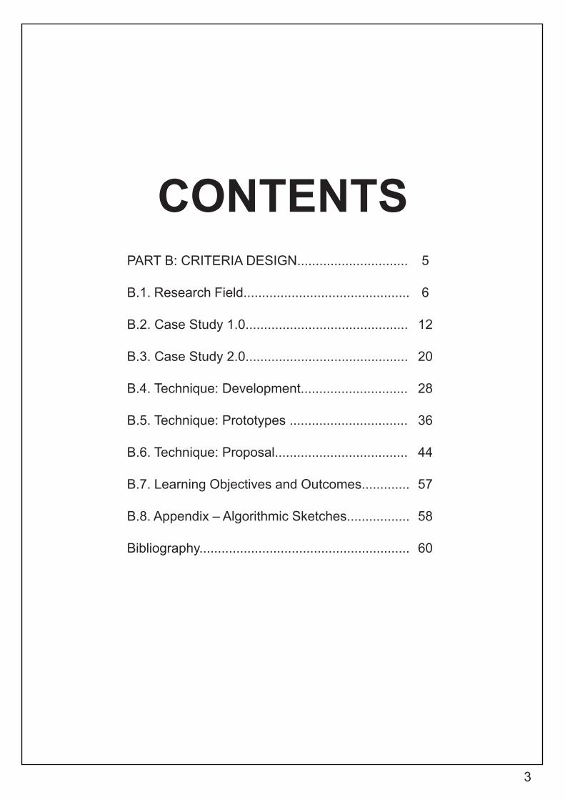
CONTENTSPART B: CRITERIA DESIGN..............................
B.1. Research Field.............................................
B.2. Case Study 1.0............................................
B.3. Case Study 2.0............................................
B.4. Technique: Development.............................
B.5. Technique: Prototypes ................................
B.6. Technique: Proposal....................................
B.7. Learning Objectives and Outcomes.............
B.8. Appendix – Algorithmic Sketches.................
Bibliography.........................................................
5
6
12
20
28
36
44
57
58
60

4
5
PART B: CRITERIA DESIGN

6
B.1.RESEARCH FIELD
7
BIOMIMICRYAs mentioned in my conclusion for Part A: Conceptualization, the availability of parametric designing has given us such a powerful tool, that can really shape our future. The big question we should ask ourselves then, is what kind of future do we want? With global warming and climate change becoming more and more drastic as the years go by, I believe the future we should strive for is one that is sustainable. So, how can we develop a sustainable future? Where can we look to for guides to sustainability?
Nature has always been around and remains the source from which everything comes from. It thrives and survives, supporting itself throughout millions and millions of years. From the structural intri-cacy of the bee’s honeycomb to the tensile properties of a spider’s web, nature has always mesmerized us through the way it evolves and resolves problems. To add on, nature does all these without bringing any damage to its surroundings. As such, nature would be the best guide and precedent for sustainable design. Mimicking and designing based on natural principles should help us to create a future that is more sustainable.
Therefore, the research fi eld that I have chosen to undertake is bio-mimicry. Based on the Biomimicry Institute, biomimicry is defi ned as an innovative approach that pursues sustainable solutions to human challenges by emulating nature’s time-tested patterns and strategies1 . To this current age, biomimicry still remains a research fi eld that is fresh, developing and open to many opportunities. While some biomimicry designs simply take on patterns from nature, some designs have proved to be functional (sustainable) as well by adopting the strategy behind the natural patterns. The following pages showcase some designs that have taken on biomimicry as their inspiration. By understanding and exploring these projects, I hope to eventually design a water fi ltration system in the river that would act as a rubbish catchment at Merri Creek (this will be ex-plained in part B.5. Technique: Prototypes)
1. “What Is Biomimicry? – Biomimicry Institute”, Biomimicry Institute, 2016, https://biomimicry.org/what-is-biomimicry/.
8
THE EDEN PROJECT BY NICHOLAS GRIMSHAW
9
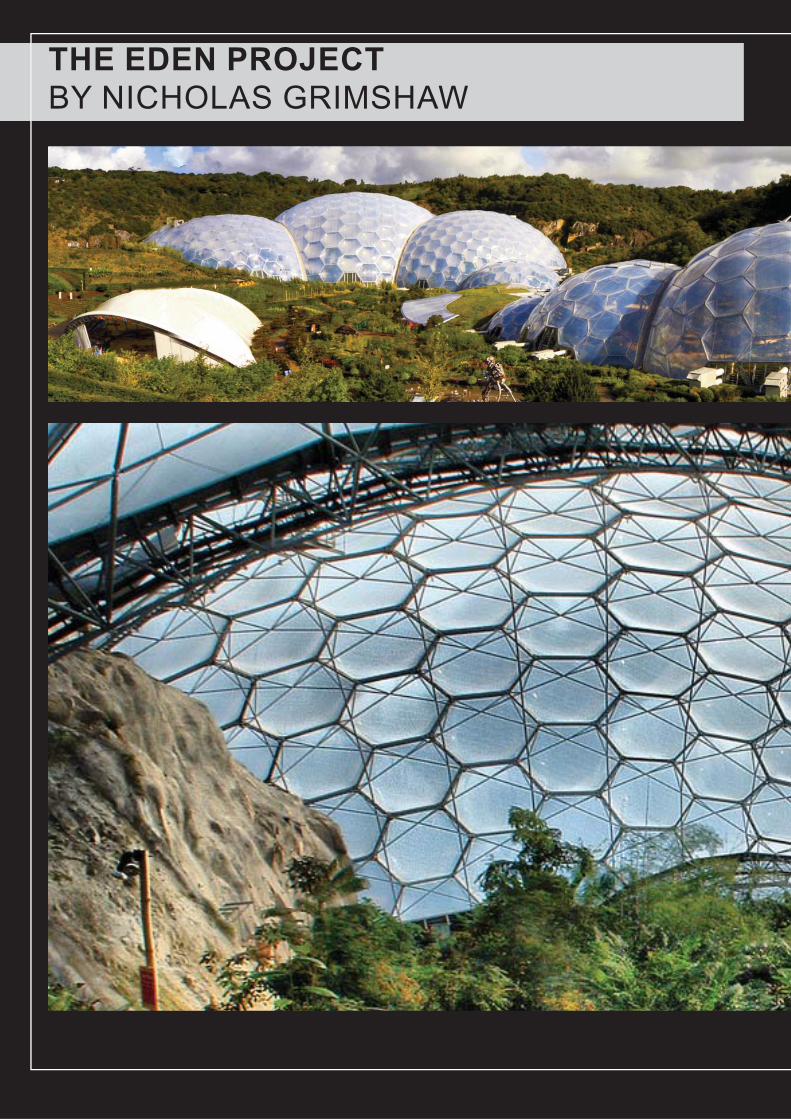
This project is located in a reclaimed Kaolite mine that was excavated in Cornwell, England, United Kingdom1 . It is a visitor attraction of artifi cial biodomes that houses an assort-ment of plants from around the world. The overall structure comprises of two large enclosures of adjoining domes that function as a greenhouse for the plant species inside.
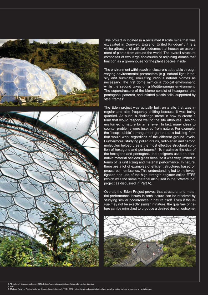
The environment within each enclosure is adaptable through varying environmental parameters (e.g. natural light inten-sity and humidity), emulating various natural biomes as necessary. The fi rst dome mimics a tropical environment, while the second takes on a Mediterranean environment. The superstructure of the biome consist of hexagonal and pentagonal patterns, and infl ated plastic cells, supported by steel frames2 .
The Eden project was actually built on a site that was ir-regular and also frequently shifting because it was being quarried. As such, a challenge arose in how to create a form that would respond well to the site attributes. Design-ers turned to nature for an answer. In fact, many ideas to counter problems were inspired from nature. For example, the “soap bubble” arrangement generated a building form that would work regardless of the different ground levels. Furthermore, studying pollen grains, radiolarian and carbon molecules helped create the most effective structural solu-tion of hexagons and pentagons3 . To maximise the size of the hexagons and pentagons, the designers used an alter-native material besides glass because it was very limited in terms of its unit sizing and material performance. In nature, there are a lot of examples of effi cient structures based on pressured membranes. This understanding led to the inves-tigation and use of the high strength polymer called ETFE (which was the same material also used in the “Watercube” project as discussed in Part A).
Overall, the Eden Project proves that structural and mate-rial performance issues in architecture can be resolved by studying similar occurrences in nature itself. Even if the is-sue may not be exactly similar in nature, the qualities of na-ture can be mimicked to produce a desired design outcome.
1. "Timeline", Edenproject.com, 2016, https://www.edenproject.com/eden-story/eden-timeline.2. Ibid. 3. Michael Pawlyn, "Using Nature's Genius In Architecture", TED, 2016, https://www.ted.com/talks/michael_pawlyn_using_nature_s_genius_in_architecture.
10
ICD-ITKE RESEARCH PAVILIONBY UNIVERSITY OF STUTTGART
11
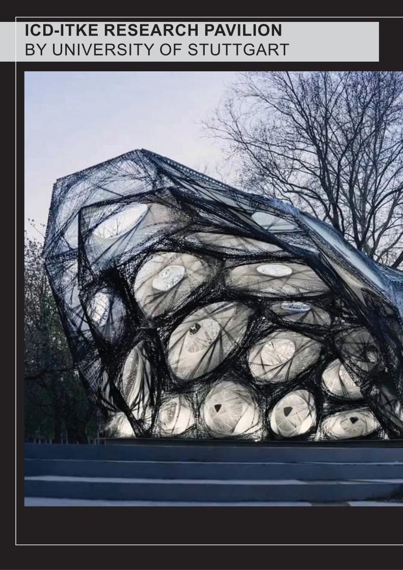
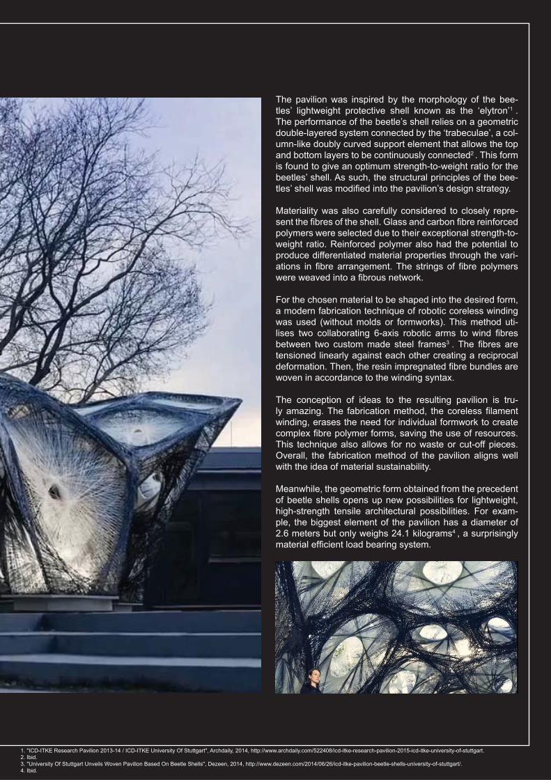
The pavilion was inspired by the morphology of the bee-tles’ lightweight protective shell known as the ‘elytron’1 . The performance of the beetle’s shell relies on a geometric double-layered system connected by the ‘trabeculae’, a col-umn-like doubly curved support element that allows the top and bottom layers to be continuously connected2 . This form is found to give an optimum strength-to-weight ratio for the beetles’ shell. As such, the structural principles of the bee-tles’ shell was modifi ed into the pavilion’s design strategy.
Materiality was also carefully considered to closely repre-sent the fi bres of the shell. Glass and carbon fi bre reinforced polymers were selected due to their exceptional strength-to-weight ratio. Reinforced polymer also had the potential to produce differentiated material properties through the vari-ations in fi bre arrangement. The strings of fi bre polymers were weaved into a fi brous network.
For the chosen material to be shaped into the desired form, a modern fabrication technique of robotic coreless winding was used (without molds or formworks). This method uti-lises two collaborating 6-axis robotic arms to wind fi bres between two custom made steel frames3 . The fi bres are tensioned linearly against each other creating a reciprocal deformation. Then, the resin impregnated fi bre bundles are woven in accordance to the winding syntax.
The conception of ideas to the resulting pavilion is tru-ly amazing. The fabrication method, the coreless fi lament winding, erases the need for individual formwork to create complex fi bre polymer forms, saving the use of resources. This technique also allows for no waste or cut-off pieces. Overall, the fabrication method of the pavilion aligns well with the idea of material sustainability.
Meanwhile, the geometric form obtained from the precedent of beetle shells opens up new possibilities for lightweight, high-strength tensile architectural possibilities. For exam-ple, the biggest element of the pavilion has a diameter of 2.6 meters but only weighs 24.1 kilograms4 , a surprisingly material effi cient load bearing system.
1. "ICD-ITKE Research Pavilion 2013-14 / ICD-ITKE University Of Stuttgart", Archdaily, 2014, http://www.archdaily.com/522408/icd-itke-research-pavilion-2015-icd-itke-university-of-stuttgart.2. Ibid. 3. "University Of Stuttgart Unveils Woven Pavilion Based On Beetle Shells", Dezeen, 2014, http://www.dezeen.com/2014/06/26/icd-itke-pavilion-beetle-shells-university-of-stuttgart/.4. Ibid.

12
B.2. CASE STUDY 1.0
13
VOLTADOMADAPTABILITY + FLEXIBILITY
14
VOLTADOMBY SKYLAR TIBBITS
15
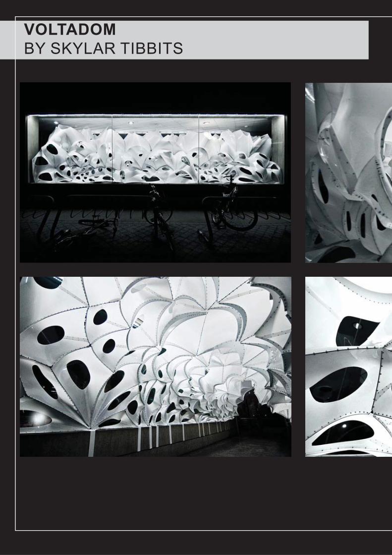
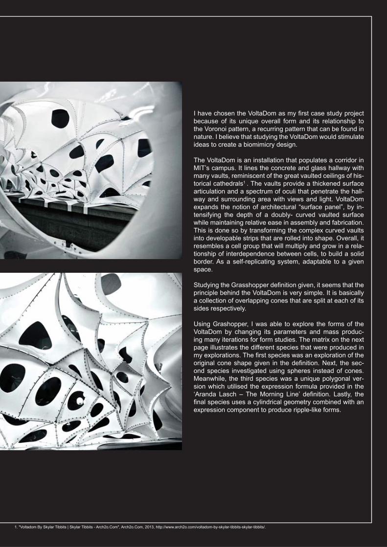
I have chosen the VoltaDom as my fi rst case study project because of its unique overall form and its relationship to the Voronoi pattern, a recurring pattern that can be found in nature. I believe that studying the VoltaDom would stimulate ideas to create a biomimicry design.
The VoltaDom is an installation that populates a corridor in MIT’s campus. It lines the concrete and glass hallway with many vaults, reminiscent of the great vaulted ceilings of his-torical cathedrals1 . The vaults provide a thickened surface articulation and a spectrum of oculi that penetrate the hall-way and surrounding area with views and light. VoltaDom expands the notion of architectural “surface panel”, by in-tensifying the depth of a doubly- curved vaulted surface while maintaining relative ease in assembly and fabrication. This is done so by transforming the complex curved vaults into developable strips that are rolled into shape. Overall, it resembles a cell group that will multiply and grow in a rela-tionship of interdependence between cells, to build a solid border. As a self-replicating system, adaptable to a given space.
Studying the Grasshopper defi nition given, it seems that the principle behind the VoltaDom is very simple. It is basically a collection of overlapping cones that are split at each of its sides respectively.
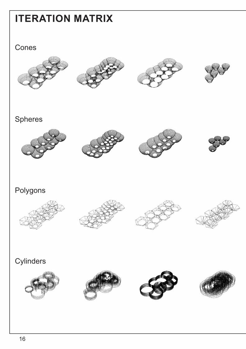
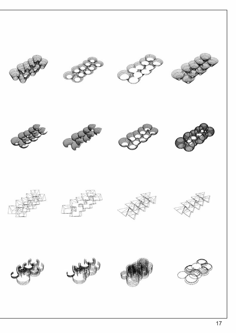
Using Grashopper, I was able to explore the forms of the VoltaDom by changing its parameters and mass produc-ing many iterations for form studies. The matrix on the next page illustrates the different species that were produced in my explorations. The fi rst species was an exploration of the original cone shape given in the defi nition. Next, the sec-ond species investigated using spheres instead of cones. Meanwhile, the third species was a unique polygonal ver-sion which utilised the expression formula provided in the ‘Aranda Lasch – The Morning Line’ defi nition. Lastly, the fi nal species uses a cylindrical geometry combined with an expression component to produce ripple-like forms.
1. "Voltadom By Skylar Tibbits | Skylar Tibbits - Arch2o.Com", Arch2o.Com, 2013, http://www.arch2o.com/voltadom-by-skylar-tibbits-skylar-tibbits/.
16
ITERATION MATRIX
Cones
Spheres
Polygons
Cylinders
17
18
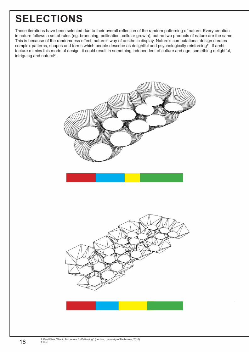
SELECTIONSThese iterations have been selected due to their overall refl ection of the random patterning of nature. Every creation in nature follows a set of rules (eg. branching, pollination, cellular growth), but no two products of nature are the same. This is because of the randomness effect, nature’s way of aesthetic display. Nature’s computational design creates complex patterns, shapes and forms which people describe as delightful and psychologically reinforcing1 . If archi-tecture mimics this mode of design, it could result in something independent of culture and age, something delightful, intriguing and natural2 .
1. Brad Elias, "Studio Air Lecture 5 - Patterning", (Lecture, University of Melbourne, 2016). 2. Ibid.
19
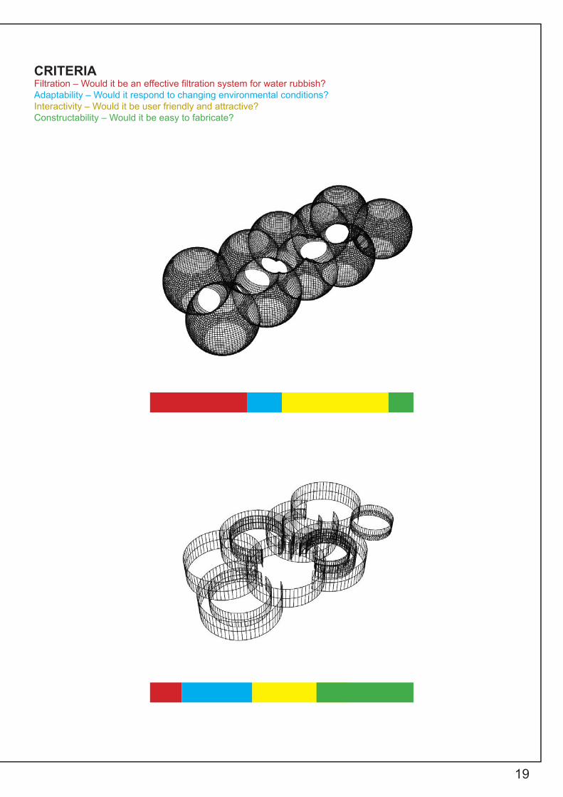
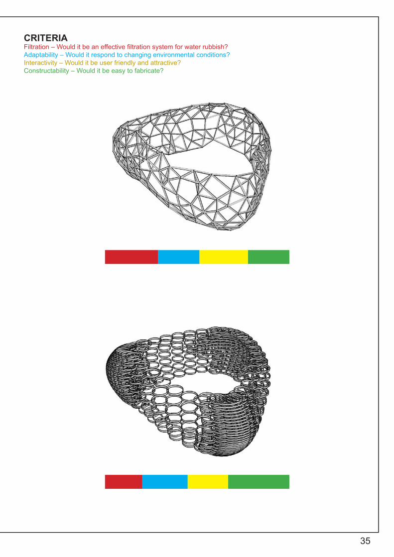
CRITERIAFiltration – Would it be an effective fi ltration system for water rubbish?Adaptability – Would it respond to changing environmental conditions?Interactivity – Would it be user friendly and attractive?Constructability – Would it be easy to fabricate?

20
B.3. CASE STUDY 2.0
21
ZA11 PAVILIONCELLULAR STRUCTURE
22
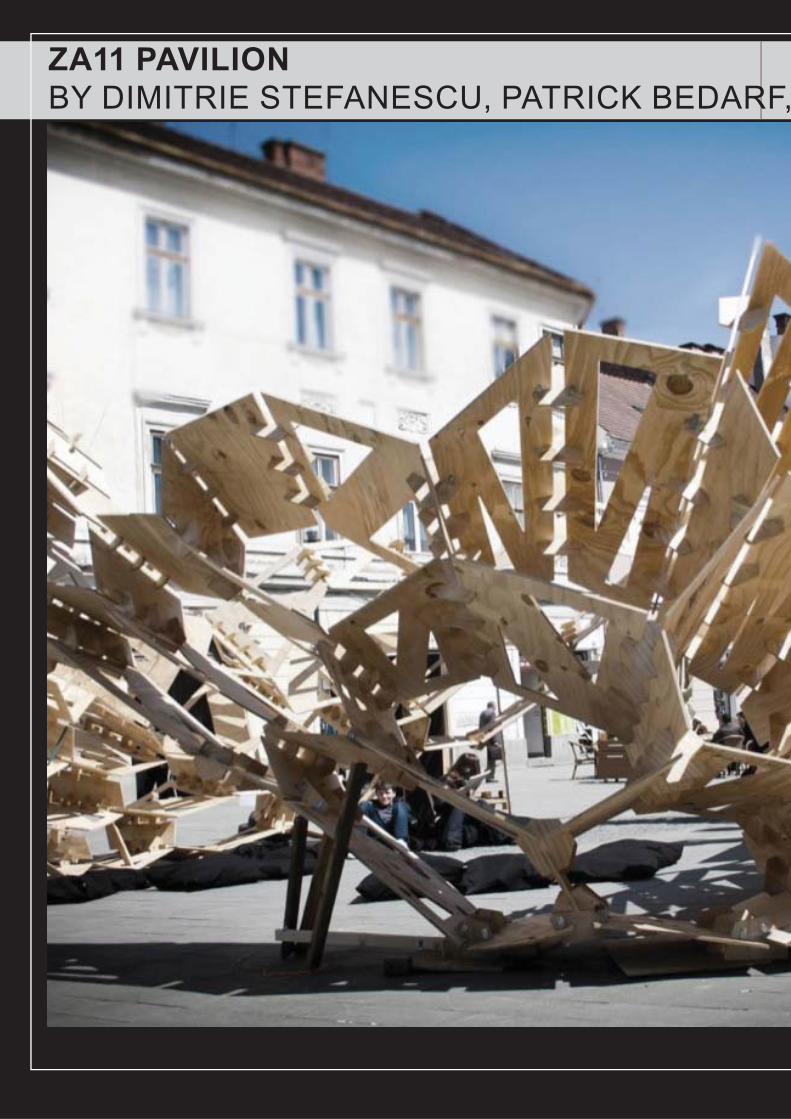
ZA11 PAVILIONBY DIMITRIE STEFANESCU, PATRICK BEDARF,
23
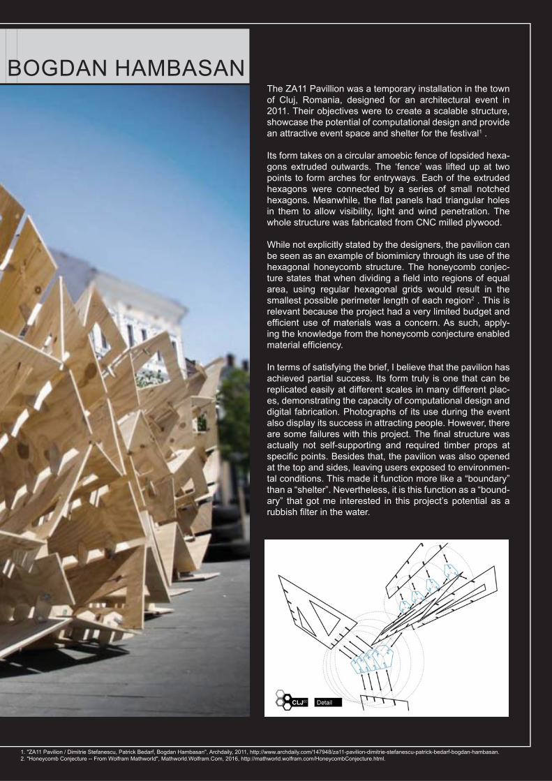
BOGDAN HAMBASANThe ZA11 Pavillion was a temporary installation in the town of Cluj, Romania, designed for an architectural event in 2011. Their objectives were to create a scalable structure, showcase the potential of computational design and provide an attractive event space and shelter for the festival1 .
Its form takes on a circular amoebic fence of lopsided hexa-gons extruded outwards. The ‘fence’ was lifted up at two points to form arches for entryways. Each of the extruded hexagons were connected by a series of small notched hexagons. Meanwhile, the fl at panels had triangular holes in them to allow visibility, light and wind penetration. The whole structure was fabricated from CNC milled plywood.
While not explicitly stated by the designers, the pavilion can be seen as an example of biomimicry through its use of the hexagonal honeycomb structure. The honeycomb conjec-ture states that when dividing a fi eld into regions of equal area, using regular hexagonal grids would result in the smallest possible perimeter length of each region2 . This is relevant because the project had a very limited budget and effi cient use of materials was a concern. As such, apply-ing the knowledge from the honeycomb conjecture enabled material effi ciency.
In terms of satisfying the brief, I believe that the pavilion has achieved partial success. Its form truly is one that can be replicated easily at different scales in many different plac-es, demonstrating the capacity of computational design and digital fabrication. Photographs of its use during the event also display its success in attracting people. However, there are some failures with this project. The fi nal structure was actually not self-supporting and required timber props at specifi c points. Besides that, the pavilion was also opened at the top and sides, leaving users exposed to environmen-tal conditions. This made it function more like a “boundary” than a “shelter”. Nevertheless, it is this function as a “bound-ary” that got me interested in this project’s potential as a rubbish fi lter in the water.
1. "ZA11 Pavilion / Dimitrie Stefanescu, Patrick Bedarf, Bogdan Hambasan", Archdaily, 2011, http://www.archdaily.com/147948/za11-pavilion-dimitrie-stefanescu-patrick-bedarf-bogdan-hambasan.2. "Honeycomb Conjecture -- From Wolfram Mathworld", Mathworld.Wolfram.Com, 2016, http://mathworld.wolfram.com/HoneycombConjecture.html.
24
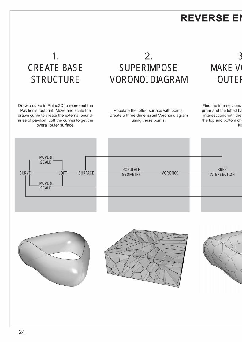
REVERSE EN
Draw a curve in Rhino3D to represent the Pavilion’s footprint. Move and scale the
drawn curve to create the external bound-aries of pavilion. Loft the curves to get the
overall outer surface.
Populate the lofted surface with points. Create a three-dimensilanl Voronoi diagram
using these points.
Find the intersections gram and the lofted baintersections with the
the top and bottom chotur
1. CREATE BASE STRUCTURE
2. SUPERIMPOSE
VORONOI DIAGRAM
3MAKE VO
OUTER
CURVE
MOVE & SCALE
MOVE & SCALE
LOFT SURFACE VORONOIPOPULATE GEOMETRY
BREPINTERSECTION

25
NGINEERING
of the 3D Voronoi dia-ase surface. Join these curves that represent ords of the base struc-re.
Scale the joined elements to form the inner skin of the Pavilion.
Loft between the inner and outer skins. Ensure that the ‘Join’ component has been grafted otherwise lofting does not work as
intended.
3. ORONOI R SKIN
4. MAKE VORONOI
INNER SKIN
5. LOFT BETWEEN
TWO SKINS
JOIN SCALE LOFT BREP
26
R E E N G I N E E R I N G DIFFICULTIES
One of the diffi culties encountered was the creation of a set of irregularly shaped hexagons. To overcome that, I utilized the Vo-ronoi diagram instead to replicate this effect. It was also tricky to get the fi nal loft between the inner and outer skin right. The solution was to simply graft the inputs to the ‘Join’ component as mentioned in Step 3 previously, enabling the correct data fl ow. I also struggled a lot trying to recreate the triangular perforations in the panels but failed to do so fi nally. In my attempt, I explod-ed the ‘Brep’ from Step 5 into component parts (faces, edges and vertices) and connected the ‘faces’ output to the recipient ‘surface’ input for the ‘surface morph’ component. A mock up rectangular surface with triangular subtractions in Rhino was made an imported into Grasshopper as a geometry. This was then connected to ‘geometry’ input of the ‘surface morph’, and a bounding box delineating the perimeter of the imported geome-try was connected to the ‘R’ input. The domain of the faces were deconstructed to ‘U’ and ‘V’ inputs. Meanwhile, the domain of the geometry bounding box was set as the ‘W’ input. A problem then occurred with the ‘U’ and ‘W’ extents in which ‘no data could be collected’. The last diffi culty I experienced was the creation of the small hexagonal notches that connect each plate together. The problem that occurred was that some of the lofted plates were ‘non-planar’ resulting in several missing notches that could not be auto-generated by the grasshopper script. After many dedi-cated hours of attempting to resolve these issues, I had to fi nally accept the form I have created due to time constraints. Given more time, I would love to be able to learn how to automatically generate the joints in this project and the perforations as well.
27
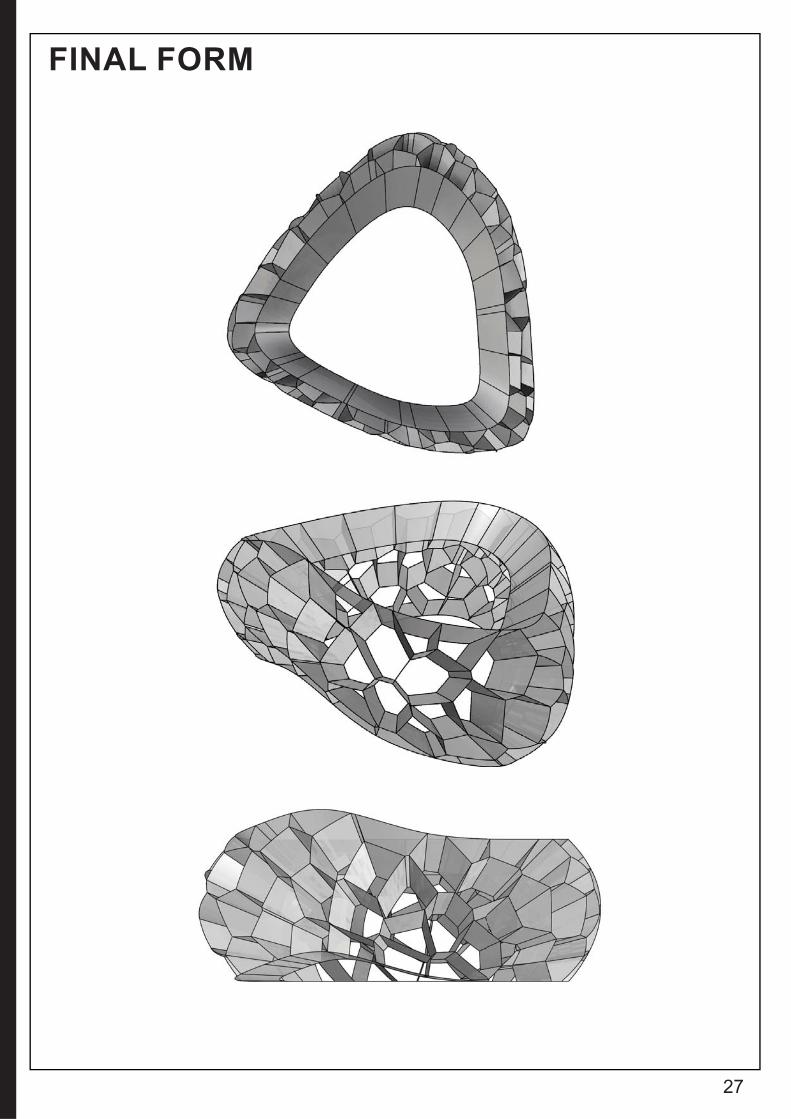
FINAL FORM

28
B.4. TECHNIQUE: DEVELOPMENT

29
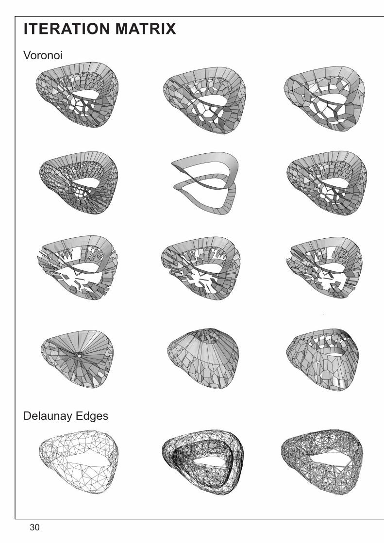
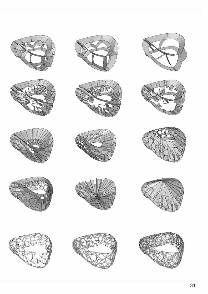
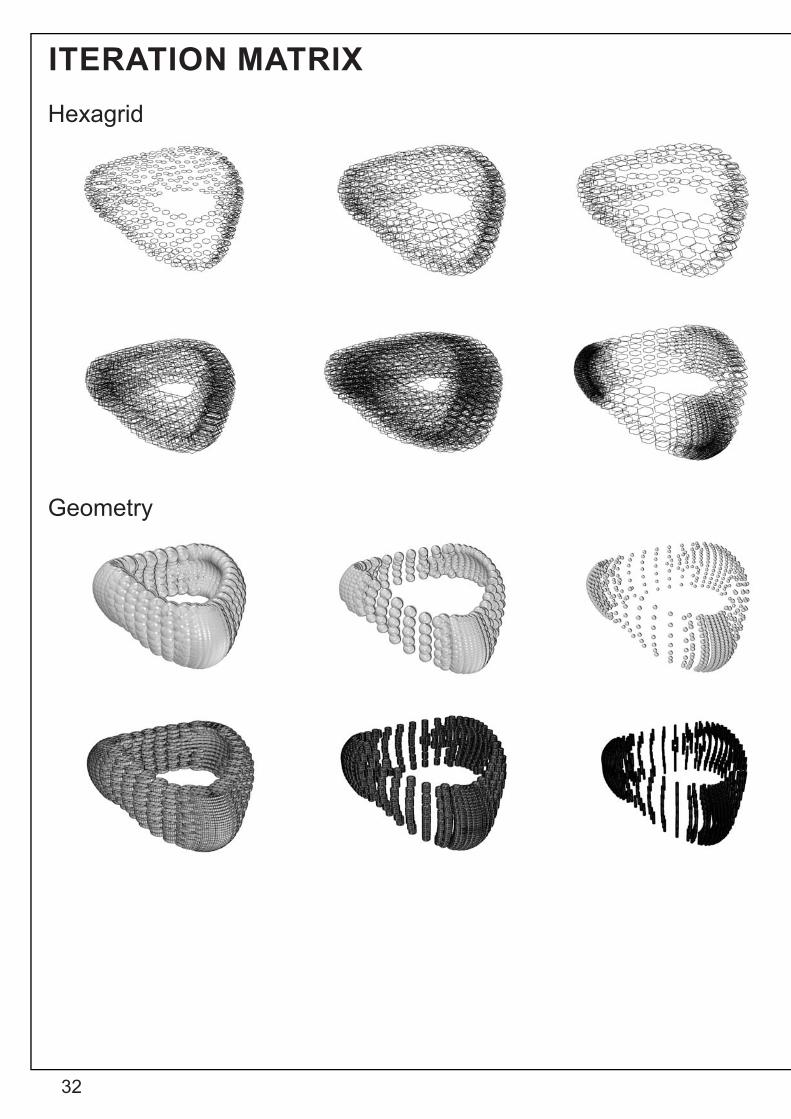
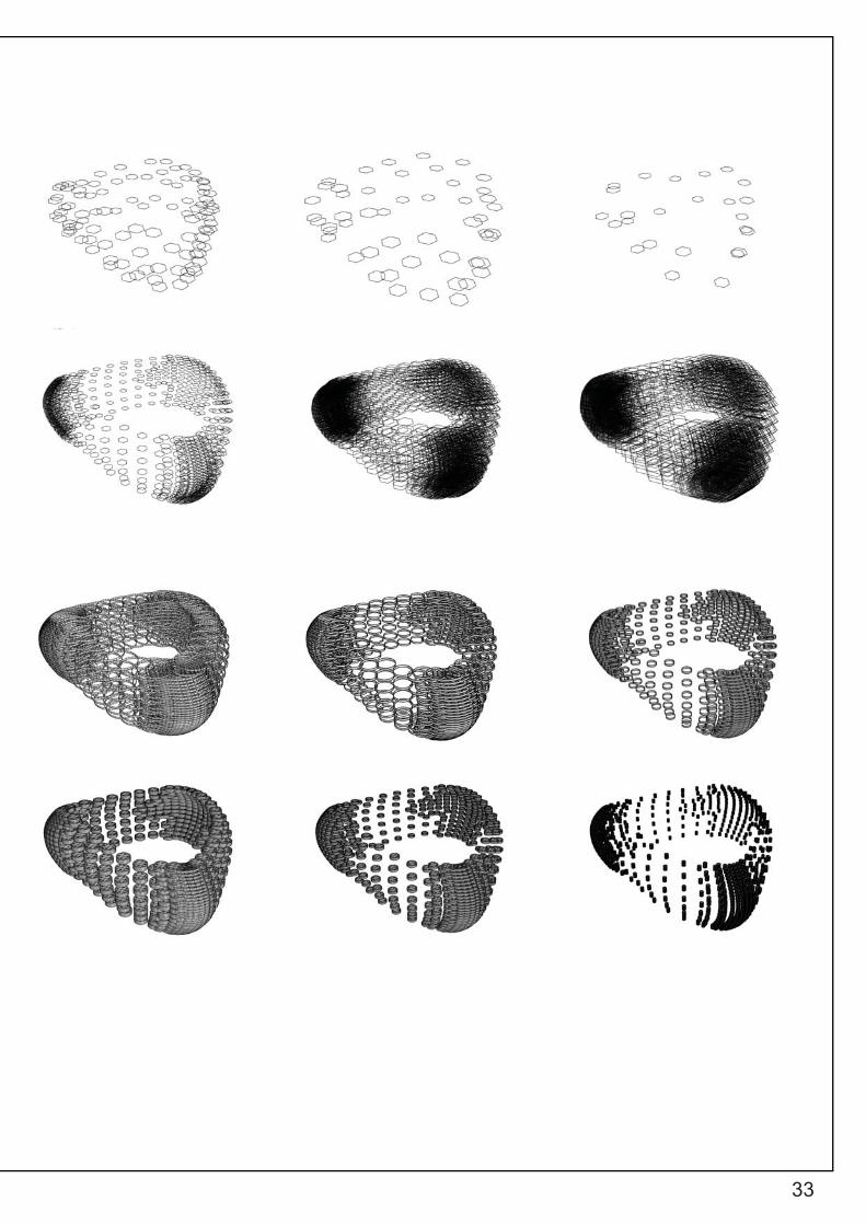
The following pages will display a set of 54 iterations of Case Study 2.0. - ZA11 Pavilion. It consists of 4 different species. The fi rst species focuses on the manipulation of the voronoi cells through its population, culling patterns, scaling and attractor points. Mean-while, the second species is an exploration into the mesh triangu-lation properties of the ‘Delaunay Edges’ component, combined with the ‘Pipe’ component. The third species investigates hexa-grids applied to the form, changing the population, size, and num-ber of hexagons in the grid. Lastly, the fourth and fi nal species studies the application of geometries to the form; spheres and cylinders (capped and opened).
DEVELOPMENT
30
ITERATION MATRIXVoronoi
Delaunay Edges
31
32
ITERATION MATRIXHexagrid
Geometry
33
34
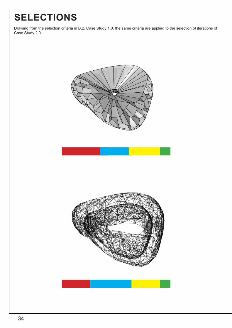
SELECTIONSDrawing from the selection criteria in B.2. Case Study 1.0, the same criteria are applied to the selection of iterations of Case Study 2.0.
35
CRITERIAFiltration – Would it be an effective fi ltration system for water rubbish?Adaptability – Would it respond to changing environmental conditions?Interactivity – Would it be user friendly and attractive?Constructability – Would it be easy to fabricate?
36
B.5. TECHNIQUE: PROTOTYPES
37
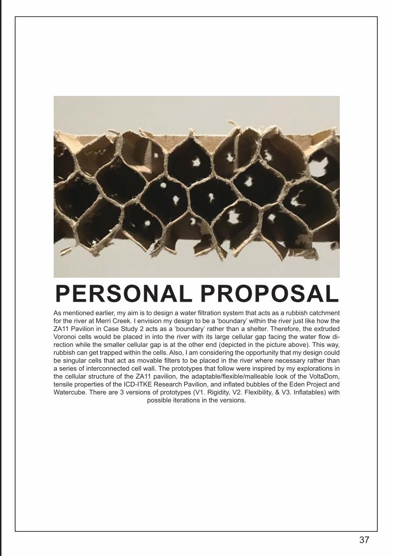
As mentioned earlier, my aim is to design a water fi ltration system that acts as a rubbish catchment for the river at Merri Creek. I envision my design to be a ‘boundary’ within the river just like how the ZA11 Pavilion in Case Study 2 acts as a ‘boundary’ rather than a shelter. Therefore, the extruded Voronoi cells would be placed in into the river with its large cellular gap facing the water fl ow di-rection while the smaller cellular gap is at the other end (depicted in the picture above). This way, rubbish can get trapped within the cells. Also, I am considering the opportunity that my design could be singular cells that act as movable fi lters to be placed in the river where necessary rather than a series of interconnected cell wall. The prototypes that follow were inspired by my explorations in the cellular structure of the ZA11 pavilion, the adaptable/fl exible/malleable look of the VoltaDom, tensile properties of the ICD-ITKE Research Pavilion, and infl ated bubbles of the Eden Project and Watercube. There are 3 versions of prototypes (V1. Rigidity, V2. Flexibility, & V3. Infl atables) with
possible iterations in the versions.
PERSONAL PROPOSAL
38
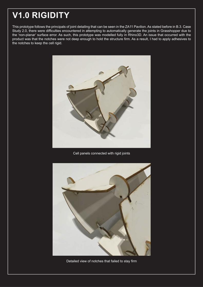
This prototype follows the principals of joint detailing that can be seen in the ZA11 Pavilion. As stated before in B.3. Case Study 2.0, there were diffi culties encountered in attempting to automatically generate the joints in Grasshopper due to the ‘non-planar’ surface error. As such, this prototype was modelled fully in Rhino3D. An issue that occurred with the product was that the notches were not deep enough to hold the structure fi rm. As a result, I had to apply adhesives to the notches to keep the cell rigid.
V1.0 RIGIDITY
Cell panels connected with rigid joints
Detailed view of notches that failed to stay fi rm

39
Inspired by the fabrication method of the VoltaDom in which the fabricated strips were rolled into vaults, I began to experiment how I could make an extruded cell become collapsible and fl attened. The following paper models show my prototypes on the relationship between the number of sides of a cell and its fl exibility. After a series of experiments, it can be concluded that all cells that have even-numbered sides (hexagons, octagons) are more fl exible and able to collapse into a fl attened surface compared to cells with odd-numbered sides (pentagons, heptagons).
V2.0 FLEXIBILITY
Even-numbered sides are able to fl atten more effectively
Odd- numbered sides fail to fully fl atten
40
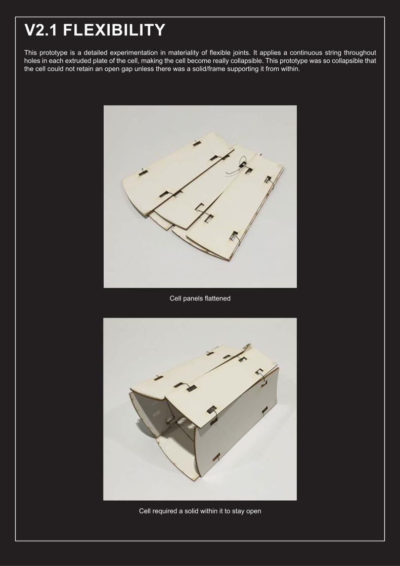
This prototype is a detailed experimentation in materiality of fl exible joints. It applies a continuous string throughout holes in each extruded plate of the cell, making the cell become really collapsible. This prototype was so collapsible that the cell could not retain an open gap unless there was a solid/frame supporting it from within.
V2.1 FLEXIBILITY
Cell panels fl attened
Cell required a solid within it to stay open
41
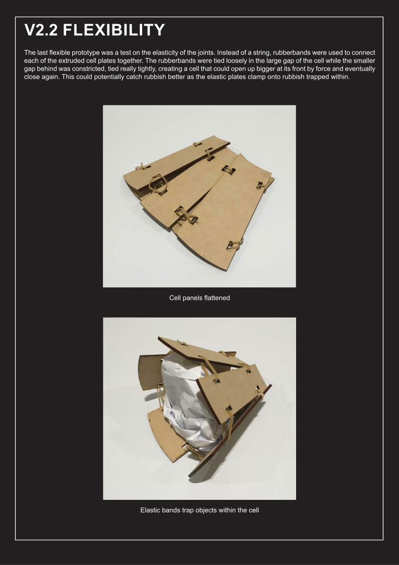
The last fl exible prototype was a test on the elasticity of the joints. Instead of a string, rubberbands were used to connect each of the extruded cell plates together. The rubberbands were tied loosely in the large gap of the cell while the smaller gap behind was constricted, tied really tightly, creating a cell that could open up bigger at its front by force and eventually close again. This could potentially catch rubbish better as the elastic plates clamp onto rubbish trapped within.
V2.2 FLEXIBILITY
Cell panels fl attened
Elastic bands trap objects within the cell
42
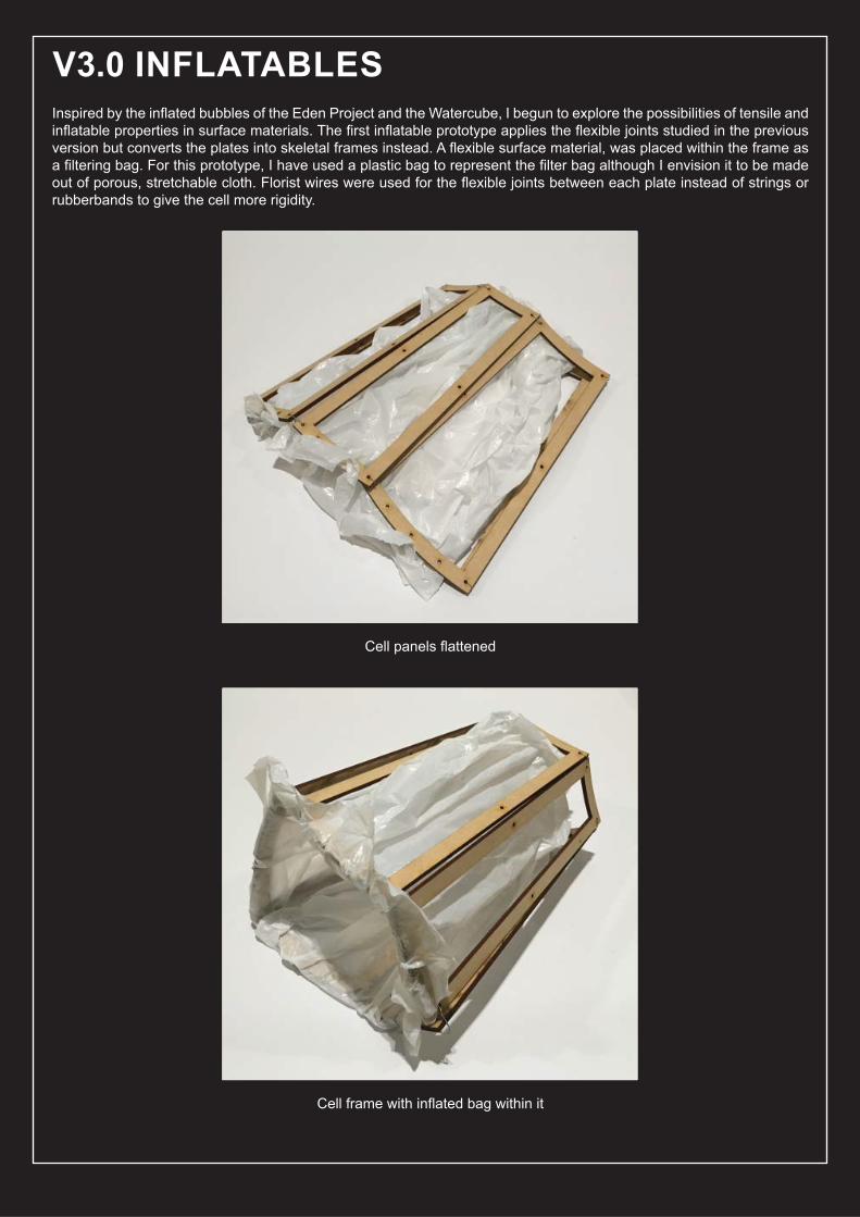
Inspired by the infl ated bubbles of the Eden Project and the Watercube, I begun to explore the possibilities of tensile and infl atable properties in surface materials. The fi rst infl atable prototype applies the fl exible joints studied in the previous version but converts the plates into skeletal frames instead. A fl exible surface material, was placed within the frame as a fi ltering bag. For this prototype, I have used a plastic bag to represent the fi lter bag although I envision it to be made out of porous, stretchable cloth. Florist wires were used for the fl exible joints between each plate instead of strings or rubberbands to give the cell more rigidity.
V3.0 INFLATABLES
Cell panels fl attened
Cell frame with infl ated bag within it
43
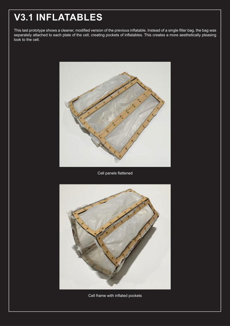
This last prototype shows a cleaner, modifi ed version of the previous infl atable. Instead of a single fi lter bag, the bag was separately attached to each plate of the cell, creating pockets of infl atables. This creates a more aesthetically pleasing look to the cell.
V3.1 INFLATABLES
Cell panels fl attened
Cell frame with infl ated pockets
44
B.6. TECHNIQUE: PROPOSAL
45
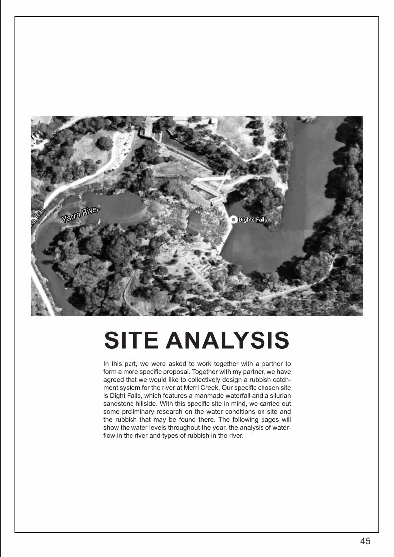
In this part, we were asked to work together with a partner to form a more specifi c proposal. Together with my partner, we have agreed that we would like to collectively design a rubbish catch-ment system for the river at Merri Creek. Our specifi c chosen site is Dight Falls, which features a manmade waterfall and a silurian sandstone hillside. With this specifi c site in mind, we carried out some preliminary research on the water conditions on site and the rubbish that may be found there. The following pages will show the water levels throughout the year, the analysis of water-fl ow in the river and types of rubbish in the river.
SITE ANALYSIS
461. "Rainfall And River Level Data - Melbourne Water", Melbournewater.Com.Au, 2016, http://www.melbournewater.com.au/content/rivers_and_creeks/rainfall_and_river_lev-el_data/rainfall_and_river_level_data.asp.
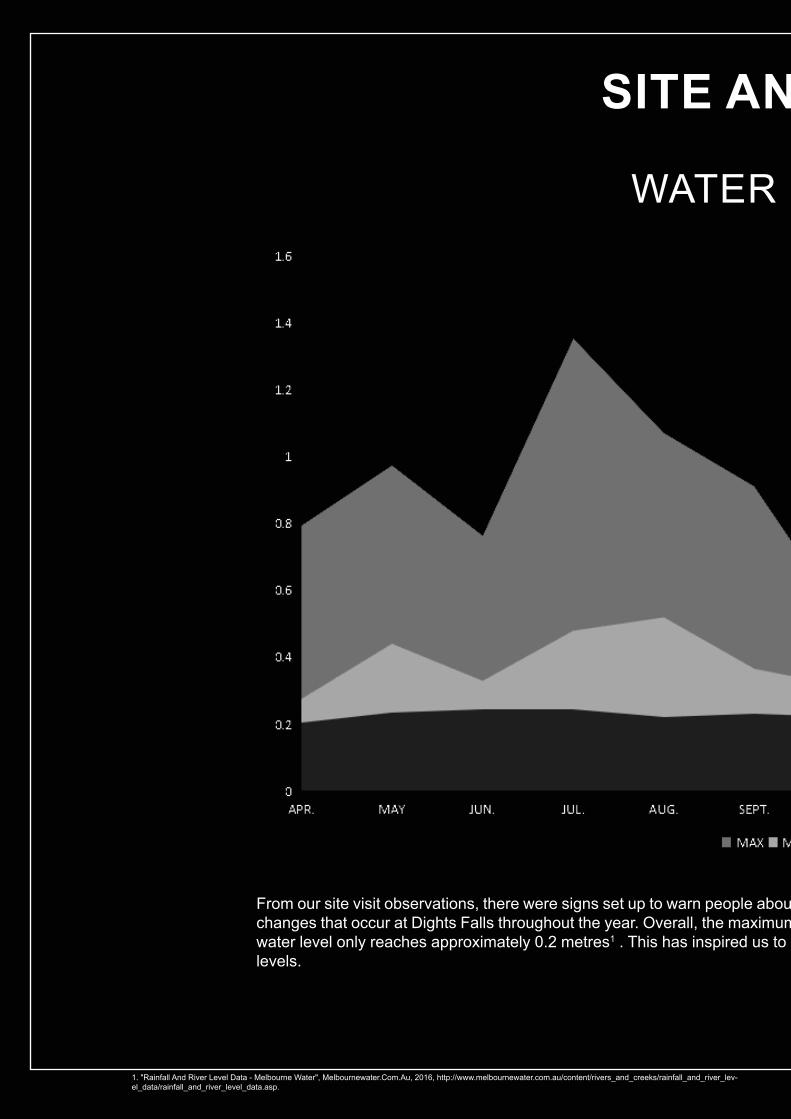
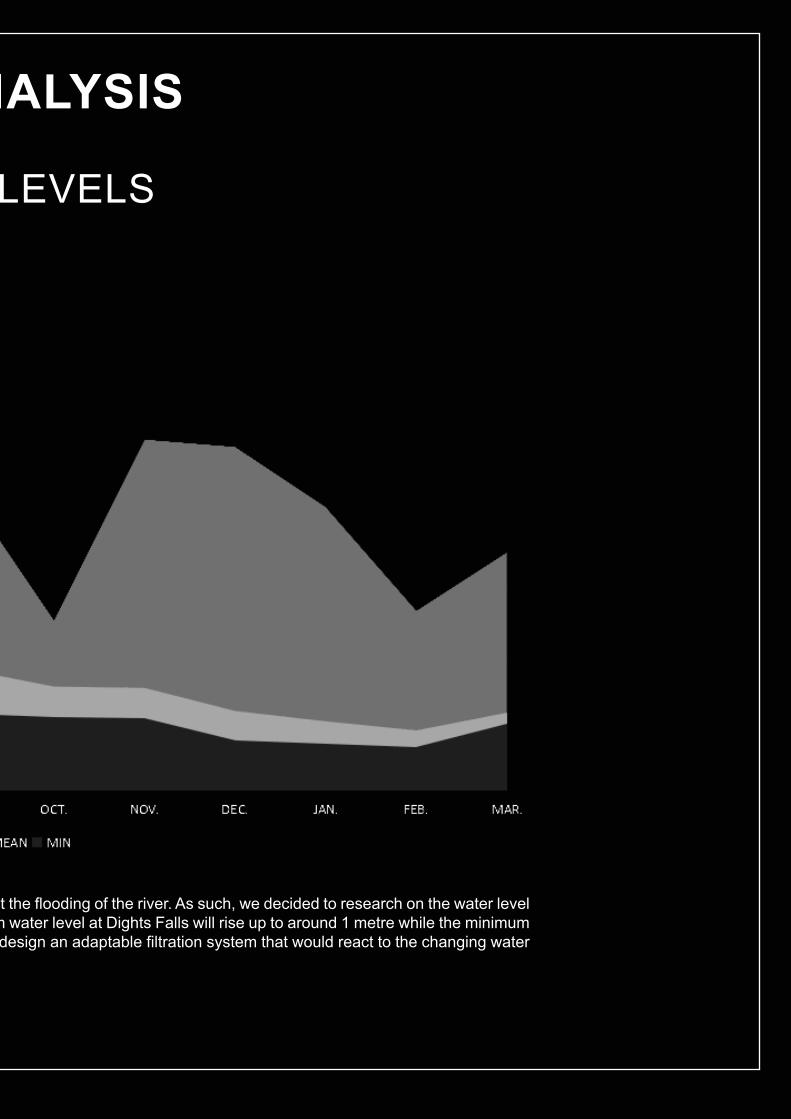
From our site visit observations, there were signs set up to warn people abouchanges that occur at Dights Falls throughout the year. Overall, the maximumwater level only reaches approximately 0.2 metres1 . This has inspired us to dlevels.
SITE AN
WATER
47
t the fl ooding of the river. As such, we decided to research on the water level m water level at Dights Falls will rise up to around 1 metre while the minimum design an adaptable fi ltration system that would react to the changing water
NALYSIS
LEVELS
48
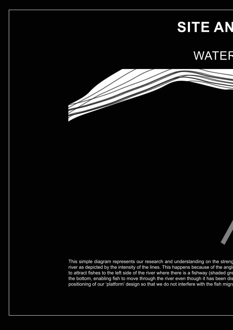
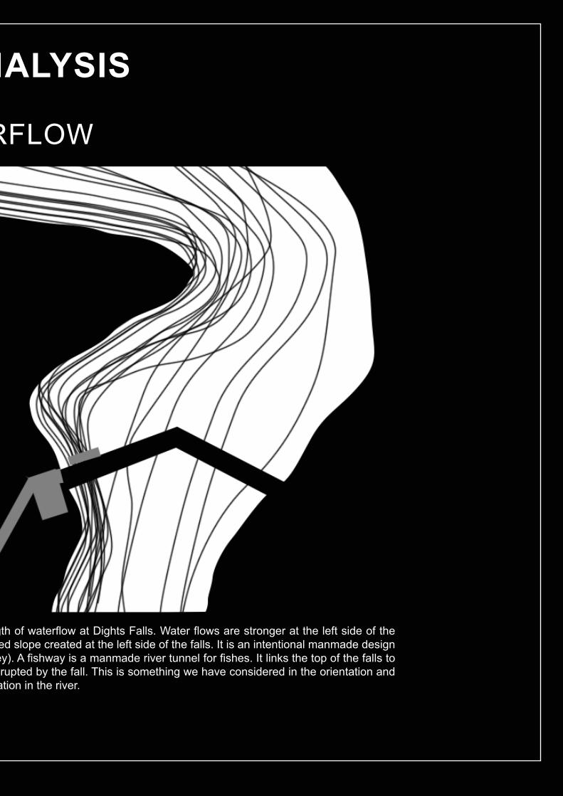
This simple diagram represents our research and understanding on the strengriver as depicted by the intensity of the lines. This happens because of the angleto attract fi shes to the left side of the river where there is a fi shway (shaded grethe bottom, enabling fi sh to move through the river even though it has been dispositioning of our ‘platform’ design so that we do not interfere with the fi sh migra
SITE AN
WATER
49
gth of waterfl ow at Dights Falls. Water fl ows are stronger at the left side of the ed slope created at the left side of the falls. It is an intentional manmade design ey). A fi shway is a manmade river tunnel for fi shes. It links the top of the falls to rupted by the fall. This is something we have considered in the orientation and
ation in the river.
NALYSIS
RFLOW
50
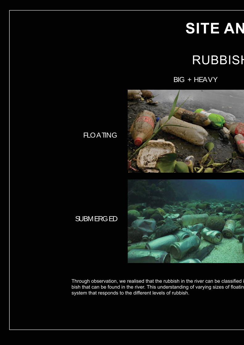
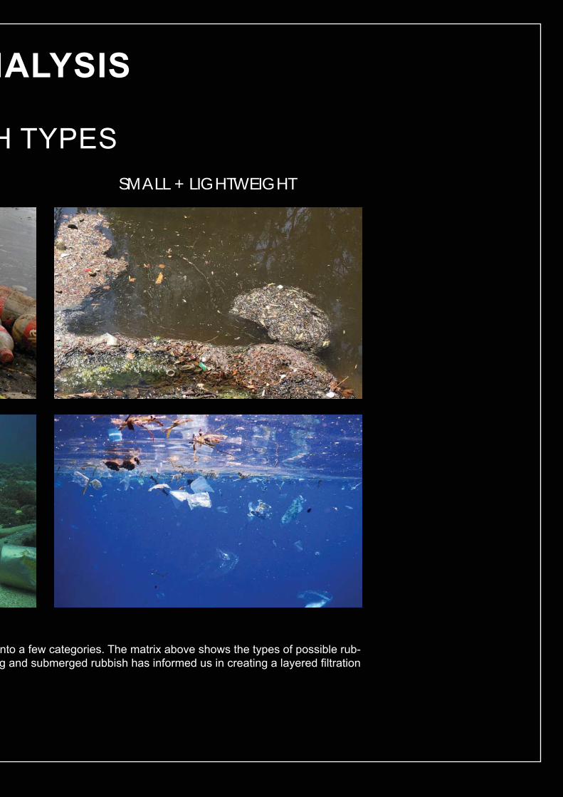
Through observation, we realised that the rubbish in the river can be classifi ed ibish that can be found in the river. This understanding of varying sizes of fl oatingsystem that responds to the different levels of rubbish.
SITE AN
BIG + HEAVY
FLOATING
SUBMERGED
RUBBISH
51
nto a few categories. The matrix above shows the types of possible rub-g and submerged rubbish has informed us in creating a layered fi ltration
NALYSIS
SMALL + LIGHTWEIGHT
H TYPES

52
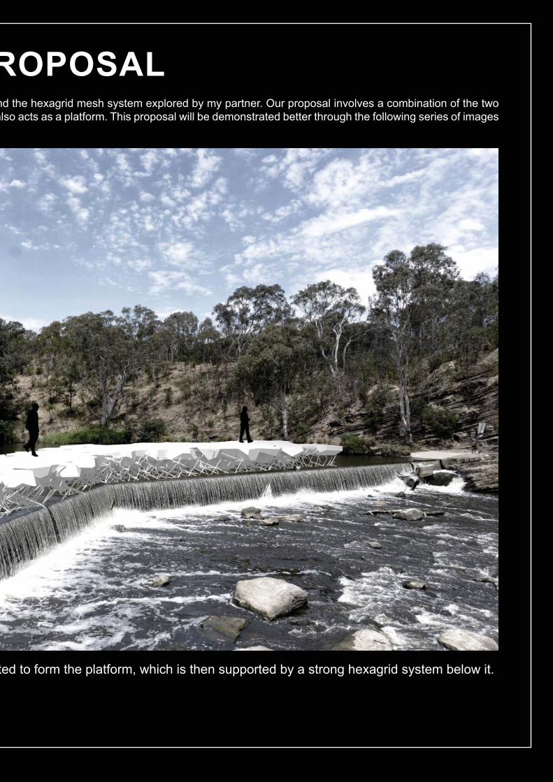
GROUP PRBased on the cellular system that I have explored ansystems to form a rubbish catchment boundary that aand diagrams.
In my previous personal proposal, I envisioned a ‘boundary wall’ of cells as a fi lter. For this new group proposal, the ‘boundary wall’ has been rotated to become a platform instead in which there will be perforations in the cell panels.
A single layer of 3D Voronoi cells are extract
53
ROPOSALnd the hexagrid mesh system explored by my partner. Our proposal involves a combination of the two also acts as a platform. This proposal will be demonstrated better through the following series of images
ted to form the platform, which is then supported by a strong hexagrid system below it.
54
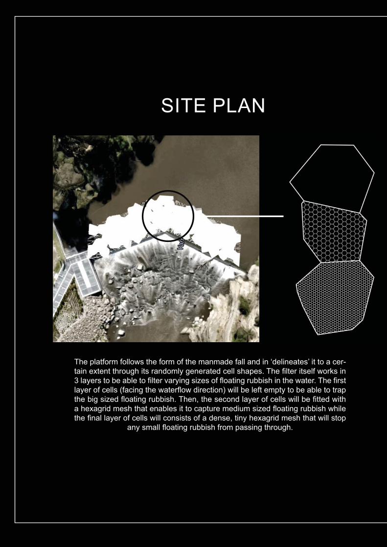
The platform follows the form of the manmade fall and in ‘delineates’ it to a cer-tain extent through its randomly generated cell shapes. The fi lter itself works in 3 layers to be able to fi lter varying sizes of fl oating rubbish in the water. The fi rst layer of cells (facing the waterfl ow direction) will be left empty to be able to trap the big sized fl oating rubbish. Then, the second layer of cells will be fi tted with a hexagrid mesh that enables it to capture medium sized fl oating rubbish while the fi nal layer of cells will consists of a dense, tiny hexagrid mesh that will stop
any small fl oating rubbish from passing through.
SITE PLAN

55
The following section diagrams show how our proposal will respond to the changes in water levels and also capture submerged rubbish
in the water.
SECTION DIAGRAM
During low water levels, the hexagrid mesh takes the main role of fi ltering the river. The mesh is designed such that it becomes in-creasingly denser towards the back mimicking the principle of the layered cell fi lters as mentioned before, able to capture varying sizes of rubbish. This underwater mesh also serves as a support for the
platform.
LOW WATER LEVEL
WATERFLOW DIRECTION
When the water level rises, our platform would be able to rise with aid from infl ated fl oaters (shaded circles) attached to the sides of the platform. This enables our design to continuously capture fl oat-ing rubbish. The platform would also be held in position by chains (dashed lines) so that it would not fl oat away and would rest back
onto the supporting hexagrid mesh when water levels subside.
HIGH WATER LEVEL
WATERFLOW DIRECTION
56
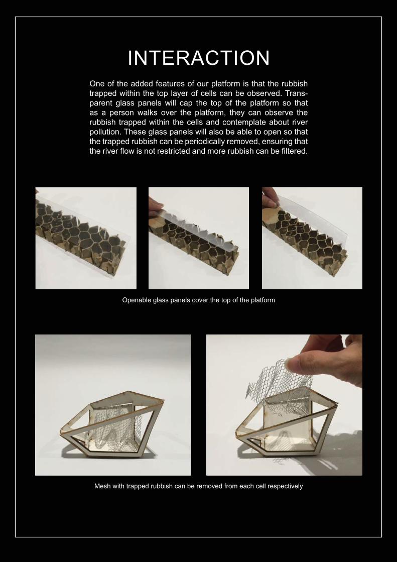
One of the added features of our platform is that the rubbish trapped within the top layer of cells can be observed. Trans-parent glass panels will cap the top of the platform so that as a person walks over the platform, they can observe the rubbish trapped within the cells and contemplate about river pollution. These glass panels will also be able to open so that the trapped rubbish can be periodically removed, ensuring that the river fl ow is not restricted and more rubbish can be fi ltered.
INTERACTION
Openable glass panels cover the top of the platform
Mesh with trapped rubbish can be removed from each cell respectively
57
Overall, Part B has really pushed my boundaries in my digital designing knowledge. Each weekly task and tutorial videos have really guided and inspired me on how I can utilize parametric model-ling to my advantage. The reverse engineering process has really engaged me with self-directed learning of algorithmic construction. It has trained me to develop a personalised repertoire of computational techniques related to meshes, triangulation, grids and geometry. Meanwhile, the it-eration process has also pushed my capabilities in generating a variety of design possibilities for a given situation. Investigating forms through parameter manipulation, versioning has really helped to provide a plethora of options in designing and generate new ideas. The comparative analysis through selection criterias has also enabled me to sift out potential designs, critically thinking about the effectiveness of a design form and how it can be applied to the brief.
One of the best learning outcomes I got from Part B is that prototyping is a very effective way of re-search and learning. Even through simple paper prototypes, I was able to understand the rules be-hind collapsible structures. Furthermore, digital fabrication was an effi cient way to quickly produce prototypes. It also made me realised that although some joints may seem like they work well in the digital realm, the real product may not connect as expected. Also, experimenting with different types of fl exible connections has made me consider the different material qualities in joints. Creat-ing physical prototypes have also allowed me to investigate the material properties and effects of infl atable plastic bags and tensile cloths and I could not precisely digitally simulate. All these have developed my skills in various 3-dimensional media from digital to physical. Based on the cellular system I explored, a potential issue that may arise is that non-modular Voronoi cells are very hard to fabricate due to its individual, unique pieces. Rest assured, I truly believe that it is this “random” effect that makes something more ‘natural’. I hope to be able to maintain this quality even as I progress into Part C for the detailed design. Keeping that in mind, I am constantly thinking about methods to portray the randomness of nature even in a modular system.
In preparation for the interim presentation, I have learned the ability to make a proper case for proposals. This was done through carrying out a site analysis and identifying the aspects we would consider in our design. Then, through a very thorough discussion with my partner and criticism from other friends out of this course, we able to anticipate and foresee potential issues in our proposal and try to resolve them as much as possible. The presentation has also helped me to develop my diagrammatic skills, presentation timing and presence.
B.7. LEARNING OUTCOMES
58
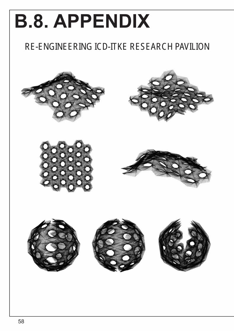
B.8. APPENDIXRE-ENGINEERING ICD-ITKE RESEARCH PAVILION

59
VS
GRAPH CONTROLLERSODD NUMBERS EVEN NUMBERS
EXPRESSIONS [sin (x) + cos (x)]
60
BIBLIOGRAPHY
Elias, Brad. “Studio Air Lecture 5 - Patterning”. Lecture, University of Melbourne, 2016.
“Honeycomb Conjecture -- From Wolfram Mathworld”. Mathworld.Wolfram.Com, 2016. http://mathworld.wolfram.com/HoneycombConjecture.html.
“ICD-ITKE Research Pavilion 2013-14 / ICD-ITKE University Of Stuttgart”. Archdaily, 2014. http://www.archdaily.com/522408/icd-itke-research-pavilion-2015-icd-itke-university-of-stuttgart.
Pawlyn, Michael. “Using Nature’s Genius In Architecture”. TED, 2016. https://www.ted.com/talks/michael_pawlyn_us-ing_nature_s_genius_in_architecture.
“Rainfall And River Level Data - Melbourne Water”. Melbournewater.Com.Au, 2016. http://www.melbournewater.com.au/content/rivers_and_creeks/rainfall_and_river_level_data/rainfall_and_river_level_data.asp.
“Timeline”. Edenproject.Com, 2016. https://www.edenproject.com/eden-story/eden-timeline.
“University Of Stuttgart Unveils Woven Pavilion Based On Beetle Shells”. Dezeen, 2014. http://www.dezeen.com/2014/06/26/icd-itke-pavilion-beetle-shells-university-of-stuttgart/.
“Voltadom By Skylar Tibbits | Skylar Tibbits - Arch2o.Com”. Arch2o.Com, 2013. http://www.arch2o.com/vol-tadom-by-skylar-tibbits-skylar-tibbits/.
“What Is Biomimicry? – Biomimicry Institute”. Biomimicry Institute, 2016. https://biomimicry.org/what-is-biomimicry/.
“ZA11 Pavilion / Dimitrie Stefanescu, Patrick Bedarf, Bogdan Hambasan”. Archdaily, 2011. http://www.archdaily.com/147948/za11-pavilion-dimitrie-stefanescu-patrick-bedarf-bogdan-hambasan.

61