Embed Size (px)
Citation preview

Procedia Engineering 80 ( 2014 ) 467 – 478
Available online at www.sciencedirect.com
1877-7058 © 2014 Published by Elsevier Ltd. This is an open access article under the CC BY-NC-ND license (http://creativecommons.org/licenses/by-nc-nd/3.0/).Selection and peer-review under responsibility of Airworthiness Technologies Research Center, Beihang University/NLAA. doi: 10.1016/j.proeng.2014.09.105
ScienceDirect
3rd International Symposium on Aircraft Airworthiness, ISAA 2013
Study on airworthiness problems of operating in supercooled large drops icing conditions for transport category airplanes
Tao HUa
1. Intruduction
*, Yan LIa, Haixia LVa, Bin TIANa
aAirworthiness Technology Research and Management Center, China Aero-Polytechnology Establishment, AVICJingshun Rd. 7, Chaoyang District, Beijing, 100028, China
Abstract
FAA has issued a Notice of Proposed Rulemaking (NPRM) on supercooled large drops (SLD) icing conditions [1].Based on following up and studying of the newest SLD icing materials, the paper gives a detailed analysis of SLD icing conditions for transport category airplanes airworthiness problems. The proposed Part 25, Appendix O about SLD icing conditions are analyzed and compared with Part 25, Appendix C, including icing clouds extend or range, altitude-temperature envelop, liquid water content (LWC) and drop diameter distribution. The changes of icing envelopes used by IPS design and certification are detailed analyzed. The proposed SLD amendment related regulations are summarized, and the proposed new §25.1420 are deeply analyzed, including the requirements of each subsection, and the requirements of the three SLD icing certification options. Moreover, the certification and compliance of the proposed §25.1420(a) directly referring to the three certification options are discussed, respectively.
© 2013 Published by Elsevier Ltd. Selection and peer-review under responsibility of ENAC.
Keywords: SLD; Icing conditions; Airworthiness; Transport catogery airplanes
In the 1990s, the FAA became aware that the types of icing conditions considered during the certification of transport category airplanes needed to be expanded to include supercooled large drops (SLD), mixed phase, and ice crystals in order to increase the level of safety during flight in icing. Safety concerns about the adequacy of the icing certification standards were brought to the forefront of public and governmental attention by a 1994 accident in Roselawn, Indiana, involving an Transport Regional
* Corresponding author, Ph.D. Tel.: +86-10-8438-0989E-mail address: [email protected]
© 2014 Published by Elsevier Ltd. This is an open access article under the CC BY-NC-ND license (http://creativecommons.org/licenses/by-nc-nd/3.0/).Selection and peer-review under responsibility of Airworthiness Technologies Research Center, Beihang University/NLAA.

468 Tao Hu et al. / Procedia Engineering 80 ( 2014 ) 467 – 478
ATR 72 series airplane. Full and vast investigations led to the conclusion that freezing drizzle conditions created a ridge of ice on the wing's upper surface aft of the deicing boots and forward of the ailerons. It was further concluded that this ridge of ice contributed to an uncommanded roll of the airplane. Based on its investigation, National Transportation Safety Board (NTSB) recommended changes to the icing certification requirements.
Nomenclature
Dmax Maximum drop size, the area of altitude-temperature envelope
Abbreviations
AC Advisory Circular AFM Airplane flight Manual
AOA Angel of attack CAAC Civil Aviation Agency of China
CFR Code of Federal Regulations CMI Continuous maximum icing
FAA Federal Aviation Administration FZDZ Freezing drizzle
FZRA Freezing rain IMI Intermittent maximum icing
LWC Liquid water content MED Median effective diameter
MVD Median volume diameter MSL Mean Sea Level
NTSB National Transportation Safety Board NPRM Notice of Proposed Rulemaking
IPS Ice protection system SLD Supercooled large drops
ZLE Freezing drizzle environment ZRE Freezing rain environment
After that accident, FAA has paid much attention on SLD icing problems. FAA tasked the Aviation Rulemaking Advisory Committee (ARAC), through its Ice Protection Harmonization Working Group (IPHWG) to study SLD weather conditions and their impacts on airworthiness, and started rulemaking and amending works. IPHWG submitted a full report of their research results and as many as 38 proposals about rulemaking [2] in December 2005. New 14 CFR 25.1420 and new Part 25 Appendix X were two most important rulemaking proposals regarding transport category airplanes, which expanded the icing conditions from current Part 25 Appendix C to supercooled large drops conditions.
At the same time, FAA has considered alternative ways to solve the safety issue before proposing new rulemaking. These alternative ways include issuing some airworthiness directives (ADs) that require the flightcrew to exit SLD icing conditions, using terminal area radar and sensors to identify areas of SLDs and warn pilots not flying into that area, and installing icing diagnostic and predictive tools in airplanes. However, due to the difficulties of detection and prediction of SLD icing conditions, these alternative ways were not mature. Even if these ways were mature, rulemaking would still be necessary to establish safety margins for inadvertent flight into such conditions and to provide an option for applicants to substantiate that the airplane is capable of safe operation in SLD conditions.
Based on ARAC's recommendations, FAA issued a NPRM titled “Airplane and Engine Certification Requirements in Supercooled Large Drop, Mixed Phase, and Ice Crystal Icing Conditions” and published in Federal Register [1] On June 29, 2010. The NPRM adopted most of ARAC's recommendations and requested for public comments. In the NPRM, FAA specifically proposed to create new regulations: §25.1324 Angle of attack systems; §25.1420 SLD icing conditions; part 25, appendix O (SLD icing conditions); part 33, appendix D. According to the latest rulemaking report released by FAA [3], it is still
469 Tao Hu et al. / Procedia Engineering 80 ( 2014 ) 467 – 478
pending for Final Rule stage until now, and it has been delayed by more than 2 years for finally coming into effect. The reason for delay in the report shows awaiting development of additional data, which means there is still some research to conduct to validate or prepare certain materials. It will be officially issued in March, 2014 according to the new projected date.
SLD icing conditions are not currently considered when certifying an airplane's ice protection systems, so, what kind of airworthiness problems will we face when the SLD regulations come into effect? This work will make comparative analysis between Appendix C and the proposed Appendix O. Concerning the SLD icing conditions, the changes of icing envelopes used by IPS design and certification will be analyzed. Moreover, the proposed SLD regulation §25.1420 will be deeply analyzed. When the SLD regulations come into effect, the compliance and validation methods will be the mainly problems. This work will give an elementary discussion of compliance the proposed §25.1420.
Since SLD will break up and splash during colliding to the surfaces of aircrafts and this process is very complicated, ice shapes computation and prediction, and their aerodynamic effects analysis become very difficult. Once operating in SLD icing condition, a lot of supercooled liquid waters will be caught by the aircraft, and then runback ice accretions problems appear as IPS cannot provide enough energy to fully clear the ice and liquid water. Runback ice accretions will bring quite adverse aerodynamic effects, and may lead to the flight control surface jams, which will seriously threat flight safety. All of these will bring a lot of new challenges to IPS design (energy requirements, protection area and means, operation, etc), SLD icing detection and warning, and airworthiness compliance verifications. This work will try to analyze these problems, and provide some possible solutions and references to the IPS airworthiness design and certification for the proposed SLD icing conditions and regulations. We hope our work can help the newest airplane type designers to learn the proposed SLD regulations amendment and consider the SLD icing certification as early as possible.
2. SLD icing conditions analysis
The proposed Appendix O is structured two parts like Appendix C of Part 25, one part defining icing conditions and one defining ice accretions. Appendix O, part I defines SLD icing conditions and part II defines the ice accretions that a manufacturer must consider when designing an airplane.
SLD icing conditions can be subdivided into icing conditions with maximum drop diameter (Dmax)
Dmax >
selected as the MVD threshold since it represents the maximum MED of 14 CFR Part 25, Appendix C continuous maximum icing conditions (stratiform clouds). All Appendix O conditions have SLD with Dmax
Dmax Appendix O together account for almost all icing environments associated with supercooled liquid water.
In order to fully analyze SLD icing conditions and to compare them with Part 25 Appendix C, it is necessary to cite the SLD icing conditions in the proposed Appendix O as follows:
Part I—MeteorologyAppendix O icing conditions are defined by the parameters of altitude, vertical and horizontal extent,
temperature, liquid water content, and water mass distribution as a function of drop diameter distribution.(a) Freezing Drizzle (Conditions with spectra maximum drop diameters from 10
(1) Pressure altitude range: 0 to 22,000 feet MSL.(2) Maximum vertical extent: 12,000 feet.(3) Horizontal extent: standard distance of 17.4 nautical miles.
470 Tao Hu et al. / Procedia Engineering 80 ( 2014 ) 467 – 478
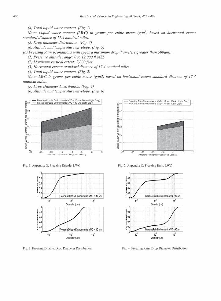
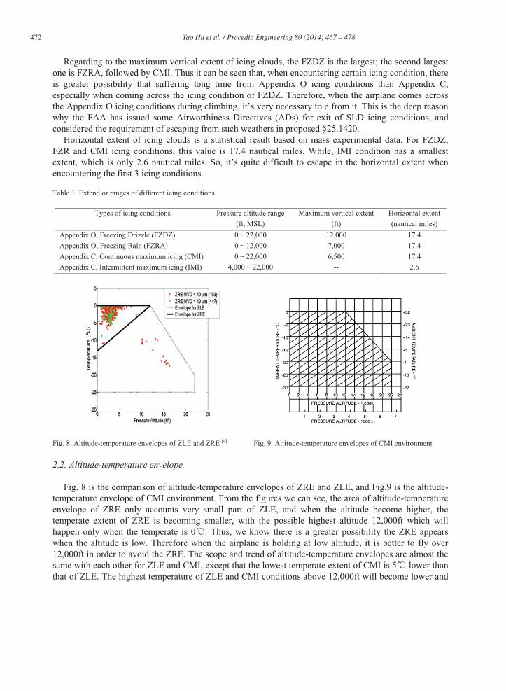
(4) Total liquid water content. (Fig. 1)Note: Liquid water content (LWC) in grams per cubic meter (g/m3) based on horizontal extent
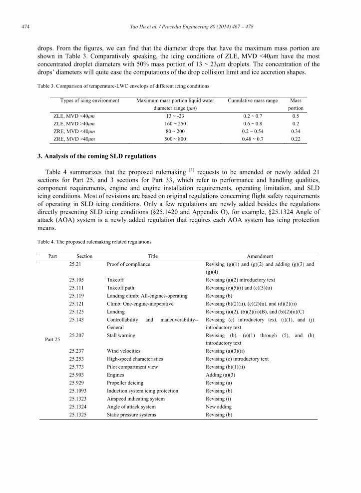
standard distance of 17.4 nautical miles.(5) Drop diameter distribution. (Fig. 3)(6) Altitude and temperature envelope. (Fig. 5)
(b) Freezing Rain (Conditions with spectra maximum drop diameters greater than 500 ):(1) Pressure altitude range: 0 to 12,000 ft MSL.(2) Maximum vertical extent: 7,000 feet.(3) Horizontal extent: standard distance of 17.4 nautical miles.(4) Total liquid water content. (Fig. 2)Note: LWC in grams per cubic meter (g/m3) based on horizontal extent standard distance of 17.4
nautical miles.(5) Drop Diameter Distribution. (Fig. 4)(6) Altitude and temperature envelope. (Fig. 6)
Fig. 1. Appendix O, Freezing Drizzle, LWC Fig. 2. Appendix O, Freezing Rain, LWC
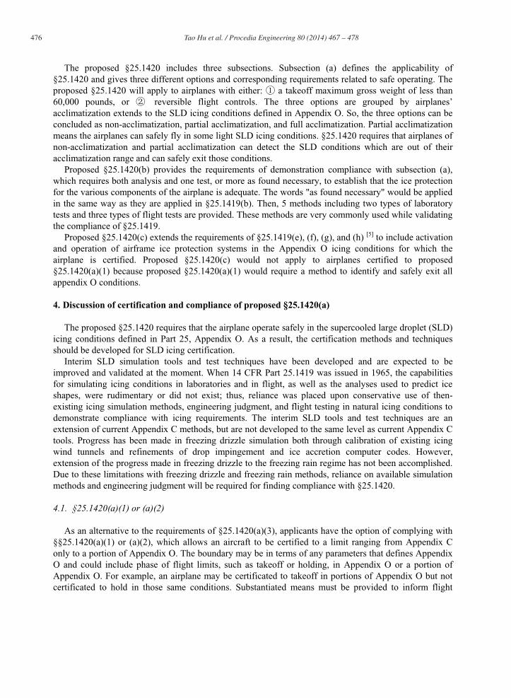
Fig. 3. Freezing Drizzle, Drop Diameter Distribution Fig. 4. Freezing Rain, Drop Diameter Distribution

471 Tao Hu et al. / Procedia Engineering 80 ( 2014 ) 467 – 478
Fig. 5. Freezing Drizzle, Temperature and Altitude Fig. 6. Freezing Rain, Temperature and Altitude
(c) Horizontal extent.The liquid water content for freezing drizzle and freezing rain conditions for horizontal extents other
than the standard 17.4 nautical miles can be determined by the value of the liquid water content determined from Figure 1 or Figure 4, multiplied by the factor provided in Fig. 7.
Fig. 7. Horizontal Extent, Freezing Drizzle and Freezing Rain
2.1. Icing clouds extend or ranges
Table 1 gives the extend and ranges of four different icing conditions defined in Part 25, Appendix C and proposed Appendix O, from which we can see that all the first 3 icing conditions could possibly appear where it’s as low as the sea level, hence when conducting the icing certification, we need to consider the influences of these 3 icing conditions on the flight safety during takeoff, and approach. The altitude ranges of atmosphere that might appear CMI and FZDZ icing conditions are the same, both 0~22,000ft. While the highest altitude where the FZRA conditions possibly happen is 12,000ft. This is due to that the higher the altitude is, the lower the atmospheric temperature is, which is not suitable for generating of the large diameter FZRA drops. Lower than 12,000ft altitude is in the climbing range of flight envelope, so we need to pay more attention to the FZRA icing conditions during the climbing period.
472 Tao Hu et al. / Procedia Engineering 80 ( 2014 ) 467 – 478
Regarding to the maximum vertical extent of icing clouds, the FZDZ is the largest; the second largest one is FZRA, followed by CMI. Thus it can be seen that, when encountering certain icing condition, there is greater possibility that suffering long time from Appendix O icing conditions than Appendix C, especially when coming across the icing condition of FZDZ. Therefore, when the airplane comes across the Appendix O icing conditions during climbing, it’s very necessary to e from it. This is the deep reason why the FAA has issued some Airworthiness Directives (ADs) for exit of SLD icing conditions, and considered the requirement of escaping from such weathers in proposed §25.1420.
Horizontal extent of icing clouds is a statistical result based on mass experimental data. For FZDZ, FZR and CMI icing conditions, this value is 17.4 nautical miles. While, IMI condition has a smallest extent, which is only 2.6 nautical miles. So, it’s quite difficult to escape in the horizontal extent when encountering the first 3 icing conditions.
Table 1. Extend or ranges of different icing conditions
Types of icing conditions Pressure altitude range
(ft, MSL)
Maximum vertical extent
(ft)
Horizontal extent
(nautical miles)
Appendix O, Freezing Drizzle (FZDZ) 0 ~ 22,000 12,000 17.4
Appendix O, Freezing Rain (FZRA) 0 ~ 12,000 7,000 17.4
Appendix C, Continuous maximum icing (CMI) 0 ~ 22,000 6,500 17.4
Appendix C, Intermittent maximum icing (IMI) 4,000 ~ 22,000 -- 2.6
Fig. 8. Altitude-temperature envelopes of ZLE and ZRE [4] Fig. 9. Altitude-temperature envelopes of CMI environment
2.2. Altitude-temperature envelope
Fig. 8 is the comparison of altitude-temperature envelopes of ZRE and ZLE, and Fig.9 is the altitude-temperature envelope of CMI environment. From the figures we can see, the area of altitude-temperature envelope of ZRE only accounts very small part of ZLE, and when the altitude become higher, the temperate extent of ZRE is becoming smaller, with the possible highest altitude 12,000ft which will happen only when the temperate is 0 . Thus, we know there is a greater possibility the ZRE appears when the altitude is low. Therefore when the airplane is holding at low altitude, it is better to fly over 12,000ft in order to avoid the ZRE. The scope and trend of altitude-temperature envelopes are almost the same with each other for ZLE and CMI, except that the lowest temperate extent of CMI is 5 lower than that of ZLE. The highest temperature of ZLE and CMI conditions above 12,000ft will become lower and

473 Tao Hu et al. / Procedia Engineering 80 ( 2014 ) 467 – 478
lower as the increase of the altitude. That’s because it is lower than 0 throughout the year at this altitude, and the temperature becomes lower as the increase of the altitude. From the figures we can also see, the area of altitude-temperature envelope of ZRE is contained by the area of ZLE envelope, while the one of ZLE is contained by that of CMI, which can be shown in mathematical expression as follows
ZRE ZLE CMI
Where presents the area of altitude-temperature envelope.This suggests that within the ZRE there is possibility that all 3 icing conditions exist; within the scope
of ( ZLE - ZRE), the icing conditions of ZLE and CMI possibly appear; while within ( CMI – ZLE), only the CMI conditions will appear.
2.3. Liquid water content (LWC)
From Fig 1 and Fig. 2 we know that the temperature-LWC envelop of Freezing Drizzle Environment (ZLE) is much larger than that of Freezing Rain Environment (ZRE). ZRE can only be formed when the temperate is within 0 ~ -13 , while ZLE can still exist when the temperate is as low as -25 . The lowest temperature of icing conditions for Appendix C is lower than those: the lowest temperate of CMI is -30 , IMI’s lowest temperate could be -40 (see Table 2).
Table 2. Comparison of temperature-LWC envelops of different icing conditions
Types of icing environment Ambient temperature range
( )
Maximum LWC at lowest
temperature (g/m3)
Maximum LWC at highest
temperature (g/m3)
Appendix O, ZLE 0 ~ -25 0.37 0.53
Appendix O, ZRE 0 ~ -13 0.31 0.38
Appendix C, CMI environment 0 ~ -30 0.20 0.80
Appendix C, IMI environment 0 ~ -40 0.25 2.90
Table 2 also provides the maximum LWC at the highest and lowest temperatures under all kinds of icing conditions, from which we can see that the maximum LWC at 0 , IMI’s is the largest, followed by ZLE’s, and ZRE’s is the smallest. The maximum LWC is one of the most important parameters for computation of energy requirements during IPS design and validation. The larger LWC is, the larger the liquid water catch rate is under the same conditions, the more energy the IPS will need. The lower the temperature is, the more energy the IPS will need under the same conditions. However, the lower the temperature is, the lower the maximum LWC will be at the same conditions. As a result, during thermal-type IPS design and assessment, we should comprehensive consider all the parameters within the 4 icing conditions’ temperature-LWC envelops, and choose the grouped parameters, that would lead to the maximum energy needs, as the input of IPS design.
2.4. Drop diameter distribution
The trajectory and collision limit of the liquid drops are directly related with their diameters. Drop diameter distribution is one of the most important parameters for the computation of drop collision limit, determination of de-/anti-icing areas, and computation of ice shapes, which is worthy to pay attention to. The curves in Fig. 3 and Fig. 4 shows the mass distribution of liquid drops of every diameter, and the slops of the curves represent the mass portion of every diameter drops. The points that have the maximum slops mean that kind of diameter drops take the maximum mass portion in the total mass oft he liquid
474 Tao Hu et al. / Procedia Engineering 80 ( 2014 ) 467 – 478
drops. From the figures, we can find that the diameter drops that have the maximum mass portion are shown in Table 3. Comparatively speaking, the icing conditions of ZLE, MVD <40 m have the most concentrated droplet diameters with 50% mass portion of 13 ~ 23 m droplets. The concentration of the drops’ diameters will quite ease the computations of the drop collision limit and ice accretion shapes.
Table 3. Comparison of temperature-LWC envelops of different icing conditions
Types of icing environment Maximum mass portion liquid water
diameter range ( )
Cumulative mass range Mass
portion
ZLE, MVD <40 13 ~ -23 0.2 ~ 0.7 0.5
ZLE, MVD >40 160 ~ 250 0.6 ~ 0.8 0.2
ZRE, MVD <40 80 ~ 200 0.2 ~ 0.54 0.34
ZRE, MVD >40 500 ~ 800 0.48 ~ 0.7 0.22
3. Analysis of the coming SLD regulations
Table 4 summarizes that the proposed rulemaking [1] requests to be amended or newly added 21 sections for Part 25, and 3 sections for Part 33, which refer to performance and handling qualities, component requirements, engine and engine installation requirements, operating limitation, and SLD icing conditions. Most of revisions are based on original regulations concerning flight safety requirements of operating in SLD icing conditions. Only a few regulations are newly added besides the regulations directly presenting SLD icing conditions (§25.1420 and Appendix O), for example, §25.1324 Angle of attack (AOA) system is a newly added regulation that requires each AOA system has icing protection means.
Table 4. The proposed rulemaking related regulations
Part Section Title Amendment
Part 25
25.21 Proof of compliance Revising (g)(1) and (g)(2) and adding (g)(3) and
(g)(4)
25.105 Takeoff Revising (a)(2) introductory text
25.111 Takeoff path Revising (c)(5)(i) and (c)(5)(ii)
25.119 Landing climb: All-engines-operating Revising (b)
25.121 Climb: One-engine-inoperative Revising (b)(2)(ii), (c)(2)(ii), and (d)(2)(ii)
25.125 Landing Revising (a)(2), (b)(2)(ii)(B), and (b)(2)(ii)(C)
25.143 Controllability and maneuverability--
General
Revising (c) introductory text, (i)(1), and (j)
introductory text
25.207 Stall warning Revising (b), (e)(1) through (5), and (h)
introductory text
25.237 Wind velocities Revising (a)(3)(ii)
25.253 High-speed characteristics Revising (c) introductory text
25.773 Pilot compartment view Revising (b)(1)(ii)
25.903 Engines Adding (a)(3)
25.929 Propeller deicing Revising (a)
25.1093 Induction system icing protection Revising (b)
25.1323 Airspeed indicating system Revising (i)
25.1324 Angle of attack system New adding
25.1325 Static pressure systems Revising (b)

475 Tao Hu et al. / Procedia Engineering 80 ( 2014 ) 467 – 478
Part Section Title Amendment
25.1420 Supercooled large drop icing conditions New adding
25.1521 Powerplant limitations Redesignating (c)(3) as (c)(4) and revising it, and
adding new (c)(3)
25.1533 Additional operating limitations Adding (c)
Appendix O Supercooled Large Drop Icing Conditions New adding
Part 33
33.68 Induction system icing Revising
33.77 Foreign object ingestion--ice Adding (a) and revising (c) introductory text,
(c)(1), (d), and (e)(1) through (4)
Appendix D Mixed Phase And Ice Crystal Icing
Envelope (Deep Convective Clouds)New adding
The second part of this work has introduced the SLD icing conditions in the proposed Appendix O and analyzed and compared them with icing conditions in Appendix C. And this part will fully introduce and analyze the proposed §25.1420 that presents the general requirements of operating in SLD icing conditions. The newly proposed §25.1420 can be read as follows:
Sec. 25.1420 Supercooled large drop icing conditions.(a) If certification for flight in icing conditions is sought, in addition to the requirements of Sec. 25.1419, an airplane with a maximum takeoff weight less than 60,000 pounds or with reversible flight controls must be capable of operating in accordance with paragraphs (a)(1), (2), or (3), of this section.
(1) Operating safely after encountering the icing conditions defined in appendix O of this part:(i) There must be a means provided to detect that the airplane is operating in appendix O icing
conditions; and(ii) Following detection of appendix O icing conditions, the airplane must be capable of operating
safely while exiting all icing conditions.(2) Operating safely in a portion of the icing conditions defined in appendix O of this part as selected
by the applicant.(i) There must be a means provided to detect that the airplane is operating in conditions that exceed
the selected portion of appendix O icing conditions; and(ii) Following detection, the airplane must be capable of operating safely while exiting all icing
conditions.(3) Operating safely in the icing conditions defined in appendix O of this part.
(b) To establish that the airplane can operate safely as required in paragraph (a) of this section, an analysis must be performed to establish that the ice protection for the various components of the airplane is adequate, taking into account the various airplane operational configurations. To verify the analysis, one, or more as found necessary, of the following methods must be used:
(1) Laboratory dry air or simulated icing tests, or a combination of both, of the components or models of the components.
(2) Laboratory dry air or simulated icing tests, or a combination of both, of models of the airplane.(3) Flight tests of the airplane or its components in simulated icing conditions, measured as necessary
to support the analysis.(4) Flight tests of the airplane with simulated ice shapes.(5) Flight tests of the airplane in natural icing conditions, measured as necessary to support the
analysis.(c) For an airplane certified in accordance with paragraph (a)(2) or (a)(3) of this section, the requirements of Sec. 25.1419 (e), (f), (g), and (h) must be met for the icing conditions defined in appendix O of this part in which the airplane is certified to operate.
476 Tao Hu et al. / Procedia Engineering 80 ( 2014 ) 467 – 478
The proposed §25.1420 includes three subsections. Subsection (a) defines the applicability of §25.1420 and gives three different options and corresponding requirements related to safe operating. The proposed §25.1420 will apply to airplanes with either: a takeoff maximum gross weight of less than 60,000 pounds, or reversible flight controls. The three options are grouped by airplanes’ acclimatization extends to the SLD icing conditions defined in Appendix O. So, the three options can be concluded as non-acclimatization, partial acclimatization, and full acclimatization. Partial acclimatization means the airplanes can safely fly in some light SLD icing conditions. §25.1420 requires that airplanes of non-acclimatization and partial acclimatization can detect the SLD conditions which are out of their acclimatization range and can safely exit those conditions.
Proposed §25.1420(b) provides the requirements of demonstration compliance with subsection (a), which requires both analysis and one test, or more as found necessary, to establish that the ice protection for the various components of the airplane is adequate. The words "as found necessary" would be applied in the same way as they are applied in §25.1419(b). Then, 5 methods including two types of laboratory tests and three types of flight tests are provided. These methods are very commonly used while validating the compliance of §25.1419.
Proposed §25.1420(c) extends the requirements of §25.1419(e), (f), (g), and (h) [5] to include activation and operation of airframe ice protection systems in the Appendix O icing conditions for which the airplane is certified. Proposed §25.1420(c) would not apply to airplanes certified to proposed §25.1420(a)(1) because proposed §25.1420(a)(1) would require a method to identify and safely exit all appendix O conditions.
4. Discussion of certification and compliance of proposed §25.1420(a)
The proposed §25.1420 requires that the airplane operate safely in the supercooled large droplet (SLD) icing conditions defined in Part 25, Appendix O. As a result, the certification methods and techniques should be developed for SLD icing certification.
Interim SLD simulation tools and test techniques have been developed and are expected to be improved and validated at the moment. When 14 CFR Part 25.1419 was issued in 1965, the capabilities for simulating icing conditions in laboratories and in flight, as well as the analyses used to predict ice shapes, were rudimentary or did not exist; thus, reliance was placed upon conservative use of then-existing icing simulation methods, engineering judgment, and flight testing in natural icing conditions to demonstrate compliance with icing requirements. The interim SLD tools and test techniques are an extension of current Appendix C methods, but are not developed to the same level as current Appendix C tools. Progress has been made in freezing drizzle simulation both through calibration of existing icing wind tunnels and refinements of drop impingement and ice accretion computer codes. However, extension of the progress made in freezing drizzle to the freezing rain regime has not been accomplished. Due to these limitations with freezing drizzle and freezing rain methods, reliance on available simulation methods and engineering judgment will be required for finding compliance with §25.1420.
4.1. §25.1420(a)(1) or (a)(2)
As an alternative to the requirements of §25.1420(a)(3), applicants have the option of complying with §§25.1420(a)(1) or (a)(2), which allows an aircraft to be certified to a limit ranging from Appendix C only to a portion of Appendix O. The boundary may be in terms of any parameters that defines Appendix O and could include phase of flight limits, such as takeoff or holding, in Appendix O or a portion of Appendix O. For example, an airplane may be certificated to takeoff in portions of Appendix O but not certificated to hold in those same conditions. Substantiated means must be provided to inform flight

477 Tao Hu et al. / Procedia Engineering 80 ( 2014 ) 467 – 478
crews when the selected icing conditions boundary is exceeded. Compliance with §25.21(g) for exiting the restricted Appendix O icing conditions must be shown. The ice shapes to be tested are those that represent the critical icing conditions within Appendix O during recognition and subsequent exit from icing conditions. Methods of defining the selected Appendix O icing conditions boundary should be considered early in the certification process, with concurrence from the appropriate certification authority.
These paragraphs of § 25.1420 require that a means be provided to flight crew to detect when the selected portion of Appendix O icing conditions is exceeded. Means for determining when the selected portion of Appendix O icing conditions is exceeded may include visual means, ice detectors or an airplane performance monitor.
(1) Ice Detectors. An ice detector system installed for compliance with §25.1420(a)(1) or (a)(2) is intended to determine when the conditions have reached the boundary of Appendix O for which the airplane has been demonstrated for safe operations. The applicant should accomplish a droplet impingement analysis and/or tests to ensure that the ice detector is properly located to function over the aircraft operational conditions and in Appendix O icing conditions. Analysis may be used in determining that the ice detector is located properly to function over the droplet range of Appendix O when validated considering methods described in SAE ARP 5903 [6]. It should be ensured that the system minimizes nuisance warnings when operating in icing conditions. The low probability of finding conditions conducive to ice accumulation in Appendix O may make natural icing flight tests difficult as a means of The applicant may use flight tests of the airplane under simulated icing conditions (icing tanker) or icing wind tunnel tests of a representative airfoil section and ice detector to demonstrate the proper functioning of the system and to correlate the signals provided by the detectors and the actual ice accretion on the surface.
(2) Aerodynamic Performance Monitor (APM). A crew alerting system could be developed using pressure probes and signal processors to quantify pressure fluctuations in the flow field from contamination over the wing surface. The technology exists but a full development is necessary before incorporating into the crew warning system.
Concerning exiting from restricted Appendix O icing conditions, flight tests are performed in accordance with 14 CFR § 25.21(g)(2) and (4) to show that the airplane can safely exit Appendix O icing conditions. AC 25.21-1X [7] gives detailed performance and handling qualities guidance.
4.2. §25.1420(a)(3)
For compliance with §25.1420(a)(3), if the AFM performance data reflects the most critical ice accretion (Appendix C and Appendix O) and no special normal or abnormal procedures are required in Appendix O conditions, then a means to indicate when the aircraft has encountered Appendix O icing conditions is not required.
5. Conclusion
This work gives a detailed analysis of SLD icing conditions for transport category airplanes airworthiness problems based on following up the newest SLD icing materials. The proposed Part 25, Appendix O about SLD icing conditions are analyzed and compared with Part 25, Appendix C, including icing clouds extend or range, altitude-temperature envelop, liquid water content (LWC) and drop diameter distribution, and the following conclusions are acquired:
FZDZ, FZRA and CMI icing conditions are all possibly encounter on the ground altitude level. Concerning the maximum vertical extent of icing clouds, the FZDZ is the largest; the second largest one is FZRA, followed by CMI.

478 Tao Hu et al. / Procedia Engineering 80 ( 2014 ) 467 – 478
The area of altitude-temperature envelope of ZRE is contained by the area of ZLE envelope, while the one of ZLE is contained by that of CMI. For the maximum LWC at 0 , IMI’s is the largest, followed by ZLE’s, and ZRE’s is the smallest. During thermal-type IPS design and assessment, we should comprehensive consider all the parameters within the 4 icing conditions’ temperature-LWC envelops, and choose the grouped parameters, that would lead to the maximum energy needs, as the input of IPS design.The icing conditions of ZLE, MVD <40 m have the most concentrated droplet diameters with 50% mass portion of 13 ~ 23 m droplets.The proposed SLD amendment related regulations are summarized, and the proposed new §25.1420
are deeply analyzed, including the requirements of each subsection, and the requirements of the three SLD icing certification options. The certification and compliance of the proposed §25.1420(a) directly referring to the three certification options are discussed, respectively. We hope our work can help the newest airplane type designers to learn the proposed SLD regulations amendment and consider the SLD icing certification as early as possible.
References
[1] Airplane and Engine Certification Requirements in Supercooled Large Drop, Mixed Phase, and Ice Crystal Icing Conditions,
CFR NPRM, Federal Register, Volume 75, Number 124, Docket No. FAA-2010-0636, June 29, 2010.
[2] Ice Protection Harmonization Working Group (IPHWG). Task 2 Working Group Report on Supercooled Large Droplet
Rulemaking, Transport Airplane Directorate IPHWG Task 2 Report, December, 2006.
[3] FAA. Report on DOT Significant Rulemakings, August, 2013.
[4] FAA. Data and Analysis for the Development of an Engineering Standard for Supercooled Large Drop Conditions,
DOT/FAA/AR-09/10, March, 2009.
[5] FAA. Amendment 25-129, Federal Register, Volume 74, p38328, Docket No. FAA-2007-27654, August 3, 2009.
[6] SAE ARP 5903, Droplet Impingement and Ice Accretion Computer Codes, October, 2003
[7] FAA ANM-110. AC 25.21-1X, Performance and Handling characteristics in the Icing Conditions Specified in Part 25,
Appendix C. February 2nd ,2006