Embed Size (px)
Citation preview
Study On Performance Evaluation And Modeling Of Temperature And Humidity Independent Control Of Air Conditioning System
Based On Operation Data M. Ukai1,*, H. Tanaka2, M. Okumiya1 and H. Tanaka1 1 Graduate School of Environmental Studies, Nagoya University, Nagoya, Aichi, 464-8603, Japan 2 NIKKEN SEKKEI LTD, Nagoya, Aichi, 460-0008, Japan ABSTRACT In this paper, analysis and evaluation of the system performance of desiccant system applied to office building are conducted. Then based on the measurement results, simulation model is developed. The object system is composed of pre-coil, desiccant rotor, sensible heat exchanger, after-coil and regenerator coil. Ground water is supplied to pre- and after-coil. Furthermore, solar heat and heat generated by combined heat and power (CHP) system are provided to regenerator coil. The evaluations are performed with COP based on outdoor air condition. The sensitivity of simulation model has been also examined on representative day. KEYWORDS Desiccant system, Operation Analysis, Modeling INTRODUCTION Temperature and humidity independent control (THIC) of air-conditioning system has been developed as efficient air conditioning system. This idea is based on separation process of latent and sensible heat. Desiccant system, as one of the THIC system, is especially focused on when renewable energy such as solar thermal is incorporated to supply heat to regenerator coil. In this study, desiccant system with polymeric adsorbents is installed in medium-size office building with some renewable energy such as solar thermal, and ground heat and water. The objective of this study is to evaluate and analyze the measurement data, and then to conduct simulation with good agreement between simulation and measurement results based on the measurement analysis. Simulation model with good agreement would be useful for proposals for better operation.
* Corresponding author email: [email protected]
854
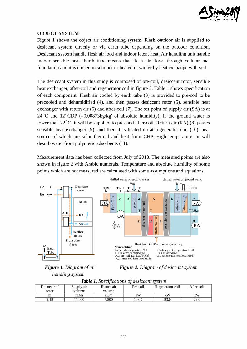
OBJECT SYSTEM Figure 1 shows the object air conditioning system. Flesh outdoor air is supplied to desiccant system directly or via earth tube depending on the outdoor condition. Desiccant system handle flesh air load and indoor latent heat. Air handling unit handle indoor sensible heat. Earth tube means that flesh air flows through cellular mat foundation and it is cooled in summer or heated in winter by heat exchange with soil. The desiccant system in this study is composed of pre-coil, desiccant rotor, sensible heat exchanger, after-coil and regenerator coil in figure 2. Table 1 shows specification of each component. Flesh air cooled by earth tube (3) is provided to pre-coil to be precooled and dehumidified (4), and then passes desiccant rotor (5), sensible heat exchanger with return air (6) and after-coil (7). The set point of supply air (SA) is at 24ºC and 12ºCDP (=0.00873kg/kg' of absolute humidity). If the ground water is lower than 22ºC, it will be supplied to pre- and after-coil. Return air (RA) (8) passes sensible heat exchanger (9), and then it is heated up at regenerator coil (10), heat source of which are solar thermal and heat from CHP. High temperature air will desorb water from polymeric adsorbents (11). Measurement data has been collected from July of 2013. The measured points are also shown in figure 2 with Arabic numerals. Temperature and absolute humidity of some points which are not measured are calculated with some assumptions and equations.
Figure 1. Diagram of air Figure 2. Diagram of desiccant system handling system
Table 1. Specifications of desiccant system Diameter of
rotor Supply air
volume Return air
volume Pre-coil Regenerator coil After-coil
m m3/h m3/h kW kW kW 2.19 11,000 7,800 103.0 93.0 29.0
desic
cant
roto
r coi
l
sens
ible
hea
t exc
hang
e
Earth
Tub
e
OA SA
RA EA
T,RH T,RH T T T,dP,u
T,RH,u T T
chilled water or ground water Qpre
Heat from CHP and solar system Qre
1
2
3 4 5 6 7
8 10 11 9
Nomenclature T:dry-bulb temperature[ºC] dP: dew point temperature [ºC] RH: relative humidity[%] u:air velocity[m/s] Qpre: pre-coil heat load[MJ/h] Qre: regenerator heat load[MJ/h] Qafter: after-coil heat load[MJ/h]
pre-
coil
afte
r-coi
l_1
afte
r-coi
l_2
rege
nera
tor c
oil
chilled water or ground water Qafter
OA
Room
Desiccant system
AHU
Earth Tube
To other floors
From other floors
1 2
3 7
OA
EA
OA
RA
SA
855
EVALUATION OF OUTDOOR AIR HANDLING SYSTEM This outdoor air handling system including desiccant system incorporates some renewable energy: ground water, ground heat and solar thermal. COP of outdoor air handling unit including desiccant system are defined as follows. Equation (1) is COP considering only effect of earth tube. Equation (2) intends to indicate the effect of earth tube and ground water. In addition to these ground heat and water effect, effect of solar thermal is considered in equation (3). To calculate the effect of solar thermal, two ways are supposed; the first is that how much amount in total heat from solar thermal and CHP is derived from solar thermal determined with proportional distribution (Eq.3_s1), and the second is that regenerator coil heat load is supplied by solar thermal preferentially (Eq.3_s2).
afterrepre
stooutet QQQ
QCOP
∑+∑+∑
∑= __
(1)
gwafterregwpre
stooutgwet QQQ
QCOP
__
__
∑+∑+∑
∑=+ (2)
gwaftersolregwpre
stooutsolgwet QQQ
QCOP
_)2(1__
__)2(1 ∑+∑+∑
∑=++ (3)
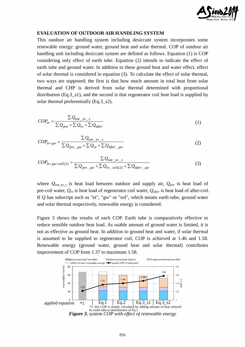
where Qout_to_s is heat load between outdoor and supply air, Qpre is heat load of pre-coil water, Qre is heat load of regenerator coil water, Qafter is heat load of after-coil. If Q has subscript such as "et", "gw" or "sol", which means earth tube, ground water and solar thermal respectively, renewable energy is considered. Figure 3 shows the results of each COP. Earth tube is comparatively effective to reduce sensible outdoor heat load. As usable amount of ground water is limited, it is not as effective as ground heat. In addition to ground heat and water, if solar thermal is assumed to be supplied to regenerator coil, COP is achieved at 1.46 and 1.58. Renewable energy (ground water, ground heat and solar thermal) contributes improvement of COP from 1.37 to maximum 1.58.
1.22
1.37 1.40
1.46
1.58
1
1.2
1.4
1.6
1.8
0
20
40
60
80
CO
P [
-]
heat
load
[GJ/m
onth
]
processed load (sensible) processed load (latent) regenerated load (sensible)
effect of each renewable energy system COP of desiccant
Figure 3. system COP with effect of renewable energy
*1 Eq.1 Eq.2 Eq.3_s1 Eq.3_s2 *1: this COP is simply calculated by adding amount of heat reduced by earth tube to denominator of Eq.1
applied equation
856
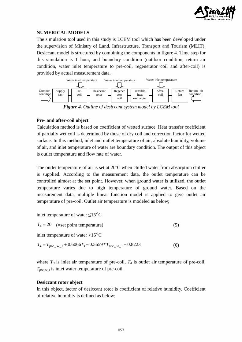
NUMERICAL MODELS The simulation tool used in this study is LCEM tool which has been developed under the supervision of Ministry of Land, Infrastructure, Transport and Tourism (MLIT). Desiccant model is structured by combining the components in figure 4. Time step for this simulation is 1 hour, and boundary condition (outdoor condition, return air condition, water inlet temperature to pre-coil, regenerator coil and after-coil) is provided by actual measurement data.
Figure 4. Outline of desiccant system model by LCEM tool
Pre- and after-coil object Calculation method is based on coefficient of wetted surface. Heat transfer coefficient of partially wet coil is determined by those of dry coil and correction factor for wetted surface. In this method, inlet and outlet temperature of air, absolute humidity, volume of air, and inlet temperature of water are boundary condition. The output of this object is outlet temperature and flow rate of water. The outlet temperature of air is set at 20ºC when chilled water from absorption chiller is supplied. According to the measurement data, the outlet temperature can be controlled almost at the set point. However, when ground water is utilized, the outlet temperature varies due to high temperature of ground water. Based on the measurement data, multiple linear function model is applied to give outlet air temperature of pre-coil. Outlet air temperature is modeled as below; inlet temperature of water ≤15ºC
204 =T (=set point temperature) (5)
inlet temperature of water >15ºC
8223.0*5659.06066.0 __3__4 −−+= iwpreiwpre TTTT (6)
where T3 is inlet air temperature of pre-coil, T4 is outlet air temperature of pre-coil, Tpre_w_i is inlet water temperature of pre-coil. Desiccant rotor object In this object, factor of desiccant rotor is coefficient of relative humidity. Coefficient of relative humidity is defined as below;
Outdoor condition
Return air condition
Supply fan
Pre- coil
Desiccant rotor
Regenerator coil
sensible heat
exchanger
After- coil
Return fan
Water inlet temperature Water inlet temperature Water inlet temperature
857
104
1051RHRHRHRH
−−
−=η (7)
where RH4 is inlet relative humidity of SA side, RH5 is outlet relative humidity of SA side, RH10 is inlet relative humidity of RA side. Coefficient of relative humidity is provided by measurement data. The value is 0.92. Sensible heat exchanger object This object is modeled with sensible exchange coefficient of SA side and RA side as below;
))/(())/(())/(( )(2
)()(_ fVVeVdVVcVbVVa rsrasarsrasarsrasaexchange +++++=η (11)
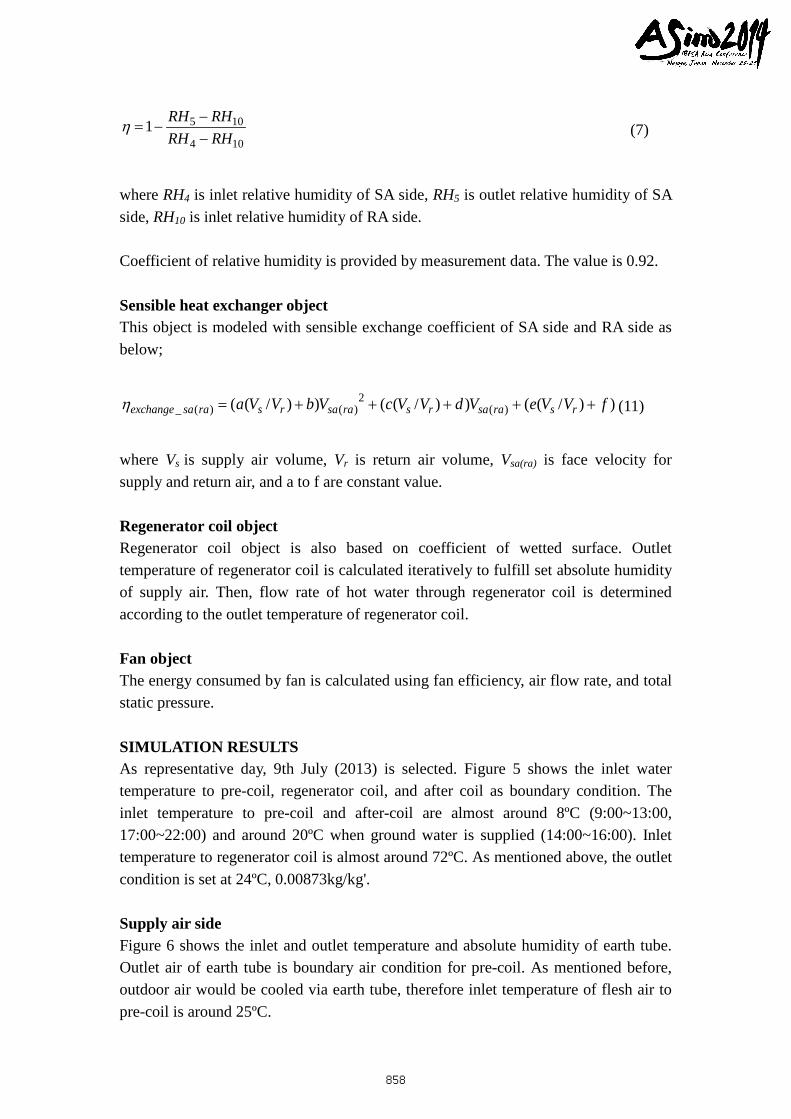
where Vs is supply air volume, Vr is return air volume, Vsa(ra) is face velocity for supply and return air, and a to f are constant value. Regenerator coil object Regenerator coil object is also based on coefficient of wetted surface. Outlet temperature of regenerator coil is calculated iteratively to fulfill set absolute humidity of supply air. Then, flow rate of hot water through regenerator coil is determined according to the outlet temperature of regenerator coil. Fan object The energy consumed by fan is calculated using fan efficiency, air flow rate, and total static pressure. SIMULATION RESULTS As representative day, 9th July (2013) is selected. Figure 5 shows the inlet water temperature to pre-coil, regenerator coil, and after coil as boundary condition. The inlet temperature to pre-coil and after-coil are almost around 8ºC (9:00~13:00, 17:00~22:00) and around 20ºC when ground water is supplied (14:00~16:00). Inlet temperature to regenerator coil is almost around 72ºC. As mentioned above, the outlet condition is set at 24ºC, 0.00873kg/kg'. Supply air side Figure 6 shows the inlet and outlet temperature and absolute humidity of earth tube. Outlet air of earth tube is boundary air condition for pre-coil. As mentioned before, outdoor air would be cooled via earth tube, therefore inlet temperature of flesh air to pre-coil is around 25ºC.
858
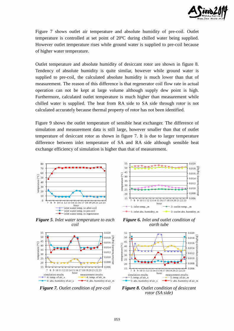
Figure 7 shows outlet air temperature and absolute humidity of pre-coil. Outlet temperature is controlled at set point of 20ºC during chilled water being supplied. However outlet temperature rises while ground water is supplied to pre-coil because of higher water temperature. Outlet temperature and absolute humidity of desiccant rotor are shown in figure 8. Tendency of absolute humidity is quite similar, however while ground water is supplied to pre-coil, the calculated absolute humidity is much lower than that of measurement. The reason of this difference is that regenerator coil flow rate in actual operation can not be kept at large volume although supply dew point is high. Furthermore, calculated outlet temperature is much higher than measurement while chilled water is supplied. The heat from RA side to SA side through rotor is not calculated accurately because thermal property of rotor has not been identified. Figure 9 shows the outlet temperature of sensible heat exchanger. The difference of simulation and measurement data is still large, however smaller than that of outlet temperature of desiccant rotor as shown in figure 7. It is due to larger temperature difference between inlet temperature of SA and RA side although sensible heat exchange efficiency of simulation is higher than that of measurement.
0
10
20
30
40
50
60
70
80
7 8 9 10 11 12 13 14 15 16 17 18 19 20 21 22 23
tem
pera
ture
[°C
]
hourinlet water temp. to after-coilinlet water temp. to pre-coilinlet water temp. to regenerator
0.006
0.008
0.010
0.012
0.014
0.016
0.018
0.020
15
20
25
30
35
40
45
50
55
7 8 9 10 11 12 13 14 15 16 17 18 19 20 21 22 23 ab
solu
te h
umid
ity [k
g/kg
']
tem
pera
ture
[°C
]
hour1: inlet temp._m 3: outlet temp. _m
1: inlet abs. humidity_m 3: outlet abs. humidity_m Figure 5. Inlet water temperature to each
coil Figure 6. Inlet and outlet condition of
earth tube
0.006
0.008
0.010
0.012
0.014
0.016
0.018
0.020
15
20
25
30
35
40
45
50
55
7 8 9 10 11 12 13 14 15 16 17 18 19 20 21 22 23
abso
lute
hum
idity
[kg/
kg']
tem
pera
ture
[°C
]
hour
4: temp. of air_s 4: temp. of air_m4: abs. humidity of air_s 4: abs. humidity of air_m
simulation results measurement results
0.006
0.008
0.010
0.012
0.014
0.016
0.018
0.020
15
20
25
30
35
40
45
50
55
7 8 9 10 11 12 13 14 15 16 17 18 19 20 21 22 23
abso
lute
tem
pera
ture
[kg/
kg']
tem
pera
ture
[°C
]
hour5. temp. of air_s 5. temp. of air_m5: abs. humidity of air_s 5: abs. humidity of air_m
simulation results measurement results
Figure 7. Outlet condition of pre-coil Figure 8. Outlet condition of desiccant
rotor (SA side)
859
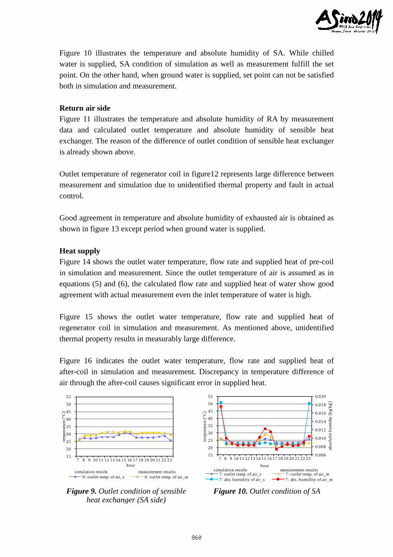
Figure 10 illustrates the temperature and absolute humidity of SA. While chilled water is supplied, SA condition of simulation as well as measurement fulfill the set point. On the other hand, when ground water is supplied, set point can not be satisfied both in simulation and measurement. Return air side Figure 11 illustrates the temperature and absolute humidity of RA by measurement data and calculated outlet temperature and absolute humidity of sensible heat exchanger. The reason of the difference of outlet condition of sensible heat exchanger is already shown above. Outlet temperature of regenerator coil in figure12 represents large difference between measurement and simulation due to unidentified thermal property and fault in actual control. Good agreement in temperature and absolute humidity of exhausted air is obtained as shown in figure 13 except period when ground water is supplied. Heat supply Figure 14 shows the outlet water temperature, flow rate and supplied heat of pre-coil in simulation and measurement. Since the outlet temperature of air is assumed as in equations (5) and (6), the calculated flow rate and supplied heat of water show good agreement with actual measurement even the inlet temperature of water is high. Figure 15 shows the outlet water temperature, flow rate and supplied heat of regenerator coil in simulation and measurement. As mentioned above, unidentified thermal property results in measurably large difference. Figure 16 indicates the outlet water temperature, flow rate and supplied heat of after-coil in simulation and measurement. Discrepancy in temperature difference of air through the after-coil causes significant error in supplied heat.
15
20
25
30
35
40
45
50
55
7 8 9 10 11 12 13 14 15 16 17 18 19 20 21 22 23
tem
pera
ture
[°C
]
hour
6: outlet temp. of air_s 6: outlet temp. of air_msimulation results measurement results
0.006
0.008
0.010
0.012
0.014
0.016
0.018
0.020
15
20
25
30
35
40
45
50
55
7 8 9 10 11 12 13 14 15 16 17 18 19 20 21 22 23 hour
abso
lult
e hu
mid
ty [k
g/kg
']
tem
pera
ture
[°C
]
7: outlet temp. of air_s 7: outlet temp. of air_m7: abs. humidity of air_s 7: abs. humidity of air_m
simulation results measurement results
Figure 9. Outlet condition of sensible
heat exchanger (SA side) Figure 10. Outlet condition of SA
860
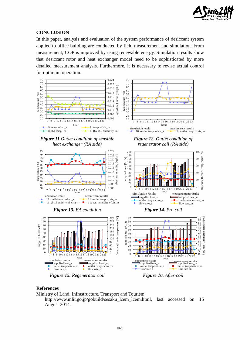
CONCLUSION In this paper, analysis and evaluation of the system performance of desiccant system applied to office building are conducted by field measurement and simulation. From measurement, COP is improved by using renewable energy. Simulation results show that desiccant rotor and heat exchanger model need to be sophisticated by more detailed measurement analysis. Furthermore, it is necessary to revise actual control for optimum operation.
0.006 0.008 0.010 0.012 0.014 0.016 0.018 0.020 0.022 0.024
20 25 30 35 40 45 50 55 60 65 70 75
7 8 9 10 11 12 13 14 15 16 17 18 19 20 21 22 23 ab
solu
te h
umid
ity [k
g/kg
']
tem
pera
ture
[°C
]
hour9: temp. of air_s 9: temp. of air_m8: RA temp._m 8: RA abs. humidity_m
20 25 30 35 40 45 50 55 60 65 70 75
7 8 9 10 11 12 13 14 15 16 17 18 19 20 21 22 23 te
mpe
ratu
re [°
C]
hour
10: outlet temp. of air_s 10: outlet temp. of air_msimulation results measurement results
Figure 11.Outlet condition of sensible
heat exchanger (RA side) Figure 12. Outlet condition of
regenerator coil (RA side)
0.006 0.008 0.010 0.012 0.014 0.016 0.018 0.020 0.022 0.024
20 25 30 35 40 45 50 55 60 65 70 75
7 8 9 10 11 12 13 14 15 16 17 18 19 20 21 22 23
abso
lute
hum
idity
[kg/
kg']
tem
pera
ture
[°C
]
hour
11: outlet temp. of air_s 11: outlet temp. of air_m11: abs. humidity of air_s 11: abs. humidity of air_m
simulation results measurement results
0
20
40
60
80
100
0 20 40 60 80
100 120 140 160 180 200
7 8 9 10 11 12 13 14 15 16 17 18 19 20 21 22 23 flow
rate
[L/m
in] t
empe
ratu
re [°
C]
supp
lied
hea
t [M
J/h]
hour
supplied heat_s supplied heat_moutlet temperature_s outlet temperature_mflow rate_s flow rate_m
simulation results measurement results
Figure 13. EA condition Figure 14. Pre-coil
0 30 60 90 120 150 180 210 240 270 300
0 20 40 60 80
100 120 140 160 180
7 8 9 10 11 12 13 14 15 16 17 18 19 20 21 22 23 flow
rate
[L/m
in] t
empe
ratu
re [°
C]
supp
lied
hea
t [M
J/h]
hour
supplied heat_s supplied heatl_moutlet temperature_s outlet temperature_mflow rate_s flow rate_m
simulation results measurement results
0 5 10 15 20 25 30 35 40 45 50 55 60 65 70
0 10 20 30 40 50 60 70 80 90
7 8 9 10 11 12 13 14 15 16 17 18 19 20 21 22 23 flow
rate
[L/m
in] t
empe
ratu
re [°
C]
supp
lied
hea
t [M
J/h]
hour
supplied heat_s supplied heat_moutlet temperature_s outlet temperature_mflow rate_s flow rate_m
simulation results measurement results
Figure 15. Regenerator coil Figure 16. After-coil
References Ministry of Land, Infrastructure, Transport and Tourism.
http://www.mlit.go.jp/gobuild/sesaku_lcem_lcem.html, last accessed on 15 August 2014.
861