Embed Size (px)
Citation preview
STUDY PAPER
ON
OTN at EDGE
Transmission Division

1
TABLE OF CONTENTS
1. Introduction 2
2. OTN Technology 3
3. OTN Frame Structure 3
4. OTN Features 5
5. Advantages of OTN at EDGE 9
6. Conclusion 11
7. References 12
2
1. Introduction
Optical transport networks have been migrating from SONET technology to WDM architectures over the
past 5–10 years. Deploying WDM systems has allowed carriers to tap enormous capacity by carrying
multiple wavelengths over a single fiber. For carriers, this means significant cost savings compared to the
cost of deploying single-channel networks, or of overlaying multiple networks for each service offering.
As this transition to WDM architectures occurred, it became painfully obvious that early WDM
implementations lacked many key features required to properly operate and maintain these optical
networks. With early WDM platforms many features, such as performance monitoring, fault detection and
isolation, a standard multiplexing hierarchy and standard communication channels, were either missing or
implemented in a proprietary fashion by each WDM equipment vendor. The Optical Transport Network
(OTN) standards, defined by the ITU-T G.709 standards committee, were developed to add SONET-like
performance monitoring, fault detection, communication channels, and multiplexing hierarchy to WDM
wavelengths.
The benefits that made SONET a robust optical transport technology, including a standardized mapping
of client signals, enhanced performance monitoring at multiple layers, comprehensive fault detection and
isolation, and embedded communications channels, were all missing from early WDM networks. Each
vendor implemented their own proprietary methods of mapping client traffic, of detecting/isolating alarm
faults, and of providing optical performance monitoring. For single-carrier networks using only one
vendor’s equipment, this lack of standardization wasn’t a serious problem. However, as optical networks
grew and became inter-connected across network boundaries, the lack of OAM standardization for WDM
became a huge liability. Essentially, the industry lost all of the benefits SONET provided for large,
multivendor interconnected networks. Without a common mapping structure, client traffic had to be de-
multiplexed into its lowest common form at carrier boundaries. For example, a carrier providing GbE
services with an nxGbE muxponder card had to break the signal back into individual GbEs at carrier
boundaries, as opposed to simply handing off 10 Gbps wavelengths. Without standard fault detection and
alarm indication signals, a fault in one portion of the network could not be communicated to other
portions of the network, especially across carrier boundaries. This led to the classic condition of a
customer complaining about receiving a bad signal, without the carrier having knowledge or awareness of
the fault condition.
Finally, without a function equivalent to “path layer monitoring,” there was no way to provide an end to
end assurance (SLA) for customer traffic. All three issues are highly sensitive for operating a network and
selling mission-critical services.

3
2. OTN technology
The Optical Transport Network (OTN) technology introduces such a solution, while offering flexibility
for new services. The Optical Transport Hierarchy, OTH, is a new transport technology developed by the
ITU for utilizing the experience and benefits of SONET/SDH and DWDM technologies. It enables the
transfer of client signals (packet-based and legacy TDM services) over multiservice transport networks. It
has all the capabilities to monitor, manage, and control each particular wavelength in the network.
OTN is an emerging technology used in NGN transport stratum. As defined by ITU-T, OTN is
“composed of a set of Optical Network Elements connected by optical fibre links, able to provide
functionality of transport, multiplexing, switching, management, supervision and survivability of optical
channels carrying client signals”. Allegedly it is able to provide “Transport for all digital payloads with
superior performance and support for the next generation of dynamic services with operational
efficiencies not expected from current optical wavelength division multiplexing (WDM) transport
solutions” and “Support for a wide range of narrowband and broadband services like SDH/SONET, IP
based services, Ethernet services, ATM services, Frame Relay services and Audio/Video services”
In simple words, OTN could be described as an advanced version of WDM, but it also absorbs the
advantages from SDH. As the telecommunication industry believes the future of the core transport
network is photonic. OTN can also be deemed as a compromised and transitional product between
electronic networks and all-optical networks.
OTN transplants the ideas and functions of OAM&P (Operation, Administration, Management and
Provision) in SDH into WDM networks, and consequently improves the performance of WDM networks
in network administration. In addition, some advanced fault management and performance monitoring
mechanisms are integrated into OTN to provide carrier-class QoS guarantee. It really realizes the
industry-desired networking capacity of building multiple-ring, mesh or star topology networks.
3. OTN Frame Structure
Adding OAM capabilities to WDM networks required creating a frame structure to “digitally wrap” or
“encapsulate” the payload, which is the basis of the ITU-T G.709 OTN standards, and commonly referred
to as G.709 Digital Wrapper. The OTN frame is very similar to a SONET frame in its structure and
format.
There are three overhead areas in an OTN frame: the Optical Payload Unit (OPU) overhead, the Optical
4
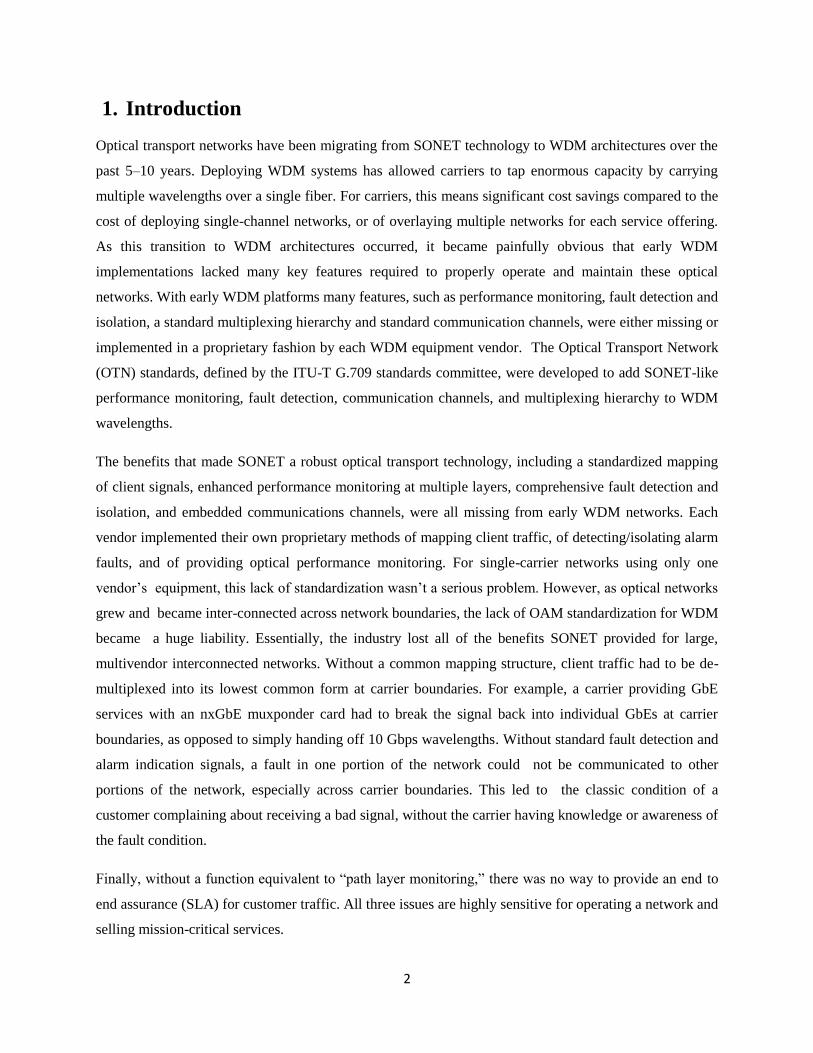
Data Unit (ODU) overhead, and the Optical Transport Unit (OTU) overhead. These overhead bytes
provide path and section performance monitoring, alarm indication, communication, and protection
switching capabilities. One additional feature is the inclusion of a Forward Error Correction (FEC)
function for each frame. The FEC improves the Optical Signal-to-Noise Ratio (OSNR) by 4 to 6 dB,
resulting in longer spans and fewer regeneration requirements.
Figure 1: OTU Frame
The OTH layers are as follows:
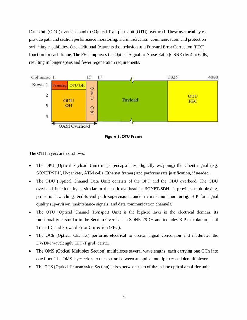
The OPU (Optical Payload Unit) maps (encapsulates, digitally wrapping) the Client signal (e.g.
SONET/SDH, IP-packets, ATM cells, Ethernet frames) and performs rate justification, if needed.
The ODU (Optical Channel Data Unit) consists of the OPU and the ODU overhead. The ODU
overhead functionality is similar to the path overhead in SONET/SDH. It provides multiplexing,
protection switching, end-to-end path supervision, tandem connection monitoring, BIP for signal
quality supervision, maintenance signals, and data communication channels.
The OTU (Optical Channel Transport Unit) is the highest layer in the electrical domain. Its
functionality is similar to the Section Overhead in SONET/SDH and includes BIP calculation, Trail
Trace ID, and Forward Error Correction (FEC).
The OCh (Optical Channel) performs electrical to optical signal conversion and modulates the
DWDM wavelength (ITU-T grid) carrier.
The OMS (Optical Multiplex Section) multiplexes several wavelengths, each carrying one OCh into
one fiber. The OMS layer refers to the section between an optical multiplexer and demultiplexer.
The OTS (Optical Transmission Section) exists between each of the in-line optical amplifier units.
5
Figure 2: OTU Client Signal Mapping
4. OTN Features
4.1 Enhanced FEC Mechanism
SDH/SONET already has Forward Error Correction (FEC) capability, but uses undefined SOH bytes to
transmit the FEC information, limiting capability and performance. OTH, however, uses a Reed-Solomon
algorithm (RS255239), which adds 7% overhead on the line rate. This improves Signal to Noise Ratio
(SNR) by 5 dB to 6 dB. The result is an increased maximum span length, saving 3R regeneration sites and
enabling more OADM nodes deployed along the signal path without 3R regeneration. This makes it more
efficient to evolve from point-to-point and mesh to OADM and ROADM topologies.
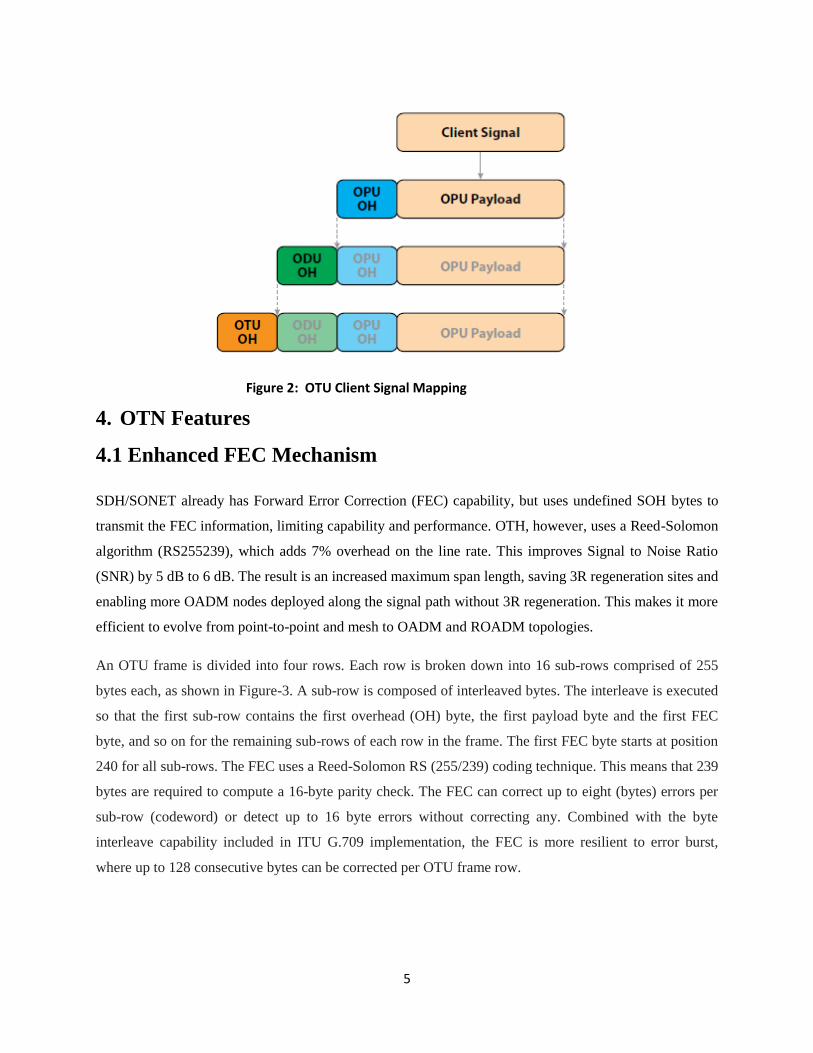
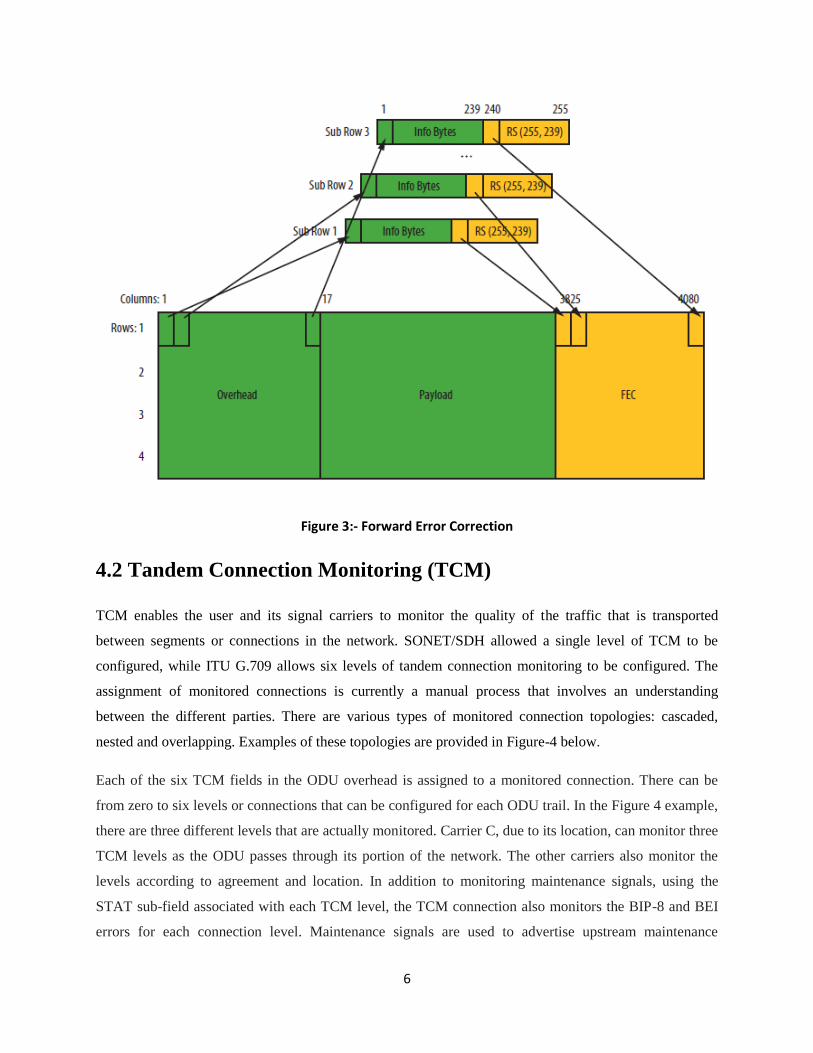
An OTU frame is divided into four rows. Each row is broken down into 16 sub-rows comprised of 255
bytes each, as shown in Figure-3. A sub-row is composed of interleaved bytes. The interleave is executed
so that the first sub-row contains the first overhead (OH) byte, the first payload byte and the first FEC
byte, and so on for the remaining sub-rows of each row in the frame. The first FEC byte starts at position
240 for all sub-rows. The FEC uses a Reed-Solomon RS (255/239) coding technique. This means that 239
bytes are required to compute a 16-byte parity check. The FEC can correct up to eight (bytes) errors per
sub-row (codeword) or detect up to 16 byte errors without correcting any. Combined with the byte
interleave capability included in ITU G.709 implementation, the FEC is more resilient to error burst,
where up to 128 consecutive bytes can be corrected per OTU frame row.
6
Figure 3:- Forward Error Correction
4.2 Tandem Connection Monitoring (TCM)
TCM enables the user and its signal carriers to monitor the quality of the traffic that is transported
between segments or connections in the network. SONET/SDH allowed a single level of TCM to be
configured, while ITU G.709 allows six levels of tandem connection monitoring to be configured. The
assignment of monitored connections is currently a manual process that involves an understanding
between the different parties. There are various types of monitored connection topologies: cascaded,
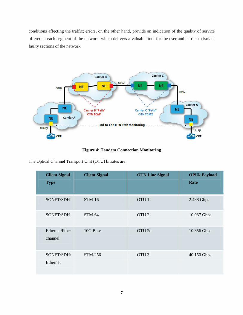
nested and overlapping. Examples of these topologies are provided in Figure-4 below.
Each of the six TCM fields in the ODU overhead is assigned to a monitored connection. There can be
from zero to six levels or connections that can be configured for each ODU trail. In the Figure 4 example,
there are three different levels that are actually monitored. Carrier C, due to its location, can monitor three
TCM levels as the ODU passes through its portion of the network. The other carriers also monitor the
levels according to agreement and location. In addition to monitoring maintenance signals, using the
STAT sub-field associated with each TCM level, the TCM connection also monitors the BIP-8 and BEI
errors for each connection level. Maintenance signals are used to advertise upstream maintenance
7
conditions affecting the traffic; errors, on the other hand, provide an indication of the quality of service
offered at each segment of the network, which delivers a valuable tool for the user and carrier to isolate
faulty sections of the network.
Figure 4: Tandem Connection Monitoring
The Optical Channel Transport Unit (OTU) bitrates are:
Client Signal
Type
Client Signal OTN Line Signal OPUk Payload
Rate
SONET/SDH STM-16 OTU 1 2.488 Gbps
SONET/SDH STM-64 OTU 2 10.037 Gbps
Ethernet/Fiber
channel
10G Base OTU 2e 10.356 Gbps
SONET/SDH/
Ethernet
STM-256 OTU 3 40.150 Gbps

8
Ethernet Upto 4-10 GBASE-R OTU 3e 41.611 Gbps
Ethernet 100 GBASE-R OTU 4 100.376 Gbps
The OTN multiplexing function is similar to PDH. Four ODU 1 signals are multiplexed into ODU 2, and
four ODU 2 signals are multiplexed into ODU 3(additional combinations are supported as well).
Figure 5: OTN mapping
4.3 ODU0
OTN switching gained broad appeal as a viable circuit to packet evolution technology option with the
addition of the sub-wavelength ODU0 rate to the OTN hierarchy. In packet transport, the two primary
currencies are GE and 10GE. Prior to the sub-wavelength rate introduction, OTN could handle 10GE
traffic using the 10.7Gbit/s OTU container, but the only container option for GE was the 2.7Gbit/s OTU1
wrapper, which required operators to waste half the available wavelength capacity when transporting GE.
With the requirement to reduce cost per bit in transport, this level of bandwidth waste was not an option
for network operators.
9
The ITU-T approved an amendment to the G.709 standard to define a new ODU container (ODU0) that is
half the size of an ODU1 container and can carry a GE stream transparently. Note that ODU0 does not
have an equivalent OTU0 for transport through a DWDM network; an ODU0 signal must be multiplexed
into an ODU1/OTU1 for transport. The existence of ODU0 enables equipment to fill the OTU1, OTU2,
etc., with GE traffic before leaving the system.
4.4 ODUflex
ODUflex, ratified by the ITU-T in December 2009, is another OTN technology that has greatly boosted
the packet-handling abilities of OTN. ODUflex is an ODU that enhances bit-transparent transport over
OTN. It can be of any rate of ODU0 (1.244 Gbit/s) or higher based on n x ODU0 increments, where n is
between 1 and 80. The n value is capped at 80 because 1.244 Gbit/s x 80 = 99.52 Gbit/s, corresponding to
the maximum size of an OTU4 payload (currently the highest rate in the OTU hierarchy). ODUflex
enables operators to transport traffic types (current and future) that don't fit neatly into the ODU0/1/2/3/4
hierarchy. In other words, with ODUflex, any form of traffic can be fit into the OTN hierarchy, based on
aggregations of 1.244Gbit/s increments. A 16G Fibre Channel service could be more efficiently carried
using ODUflex, for example. ODUflex is thus a more flexible container for OTN transport.
5. Advantages of OTN at Edge
5.1 Exhaustion of Fibre
Where fiber is scarce, OTN has proven far more economical than laying additional fibers. In addition, in
many cases laying additional fibers in metro networks is not an option, as these are all densely built up
areas with strict zoning and building restrictions.OTN also provides far greater spectral efficiency on the
fiber compared to single wavelength solution, meaning more bits per second per cycle (or hertz). Spectral
efficiency has become critical to operators as they seek the lowest cost per bit for transport equipment and
squeeze the greatest possible capacity out of their existing networks (including the installed fiber plant).
OTN systems today can provide up to 8 Tbit/s of capacity on a single fiber pair.
5.2 Reduced OPEX and CAPEX
Beyond fiber exhaust, OTN can also be used in metro Ethernet networks to create mesh and partial mesh
networks that reduce reliance on the IP layer for transit traffic. Such transit traffic occupies costly router
ports and is a strain on both capex (the ports themselves) and on opex (router space and power
consumption). OTN is required in this application to extend metro Ethernet distances so that traffic
10
doesn't need to terminate at intermediate nodes along the route. Another benefit of optical layer transport
is reduced latency for very latency-sensitive applications, such as online gaming, financial transactions
and certain cloud services.
5.3 Fixed Broadband Requirement
Fixed broadband trends in general drive OTN use in the metro core network and deeper into the
aggregation network as numbers of fixed broadband users and bandwidth per broadband user both
continue to rise. Residential fiber access services are increasing globally and drive tremendous traffic
through the aggregation and metro core network.
There are two main network development phases in the fixed broadband network evolution. In the initial
xDSL era, per-user bandwidth requirements were typically sub-10 Mbit/s. These access network speeds
drove WDM deployments into metro core networks, as the traffic generated by broadband users far
exceeded network traffic of the TDM voice and dial-up Internet era. Many operators globally reached
these xDSL bandwidth levels years ago and are now surpassing the 10Mbit/s-per-user threshold. The
telecom industry is now moving into the ultra-broadband era in which access speeds are far greater than
10 Mbit/s and set to rise to 100 Mbit/s or even as high as 1 Gbit/s per user, depending on access
technologies deployed. In addition, video services are both high bandwidth and continuous and put
particular strains on aggregation networks. As a result of these trends, in the new ultra-broadband era, we
are seeing operators increasingly move OTN into aggregation and edge networks.
5.4 Mobile Broadband Requirement
Mobile broadband – using high-speed mobile connections for packetized data and multimedia
applications – is driving the mobile industry today. As operators move from 2G and early 3G to advanced
3G and 4G-based services, subscriber bandwidth goes up dramatically. A key point is that as access
speeds go up, capacity in the backhaul network must also increase to cope with the new demands. In other
words, upgrading the mobile access network without ensuring the presence of sufficient capacity in the
backhaul network just creates a traffic bottleneck in the backhaul that renders the advanced access
networks useless.
11
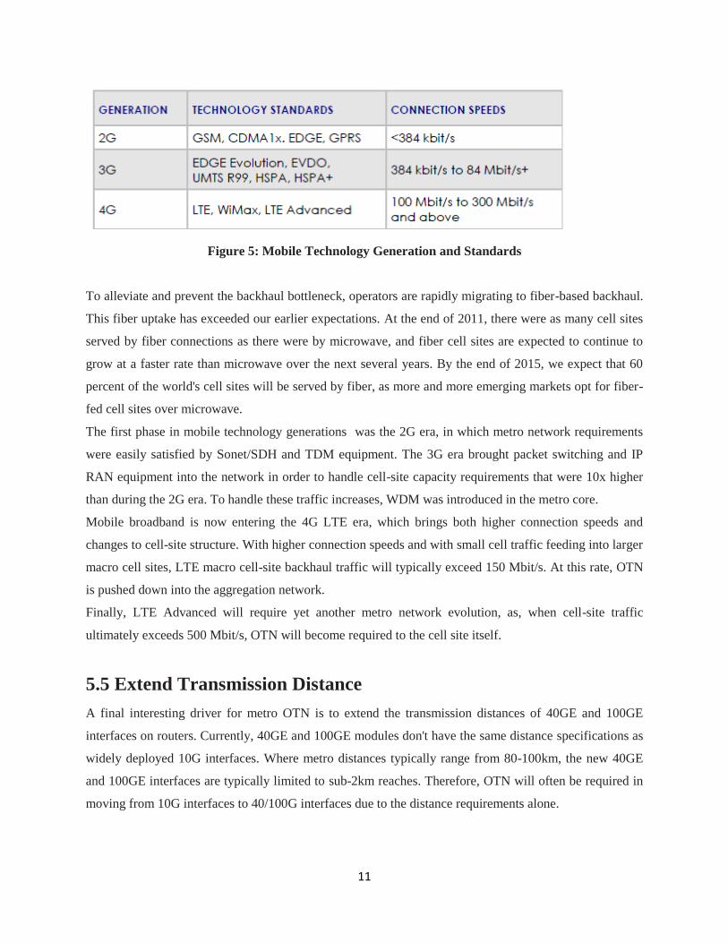
Figure 5: Mobile Technology Generation and Standards
To alleviate and prevent the backhaul bottleneck, operators are rapidly migrating to fiber-based backhaul.
This fiber uptake has exceeded our earlier expectations. At the end of 2011, there were as many cell sites
served by fiber connections as there were by microwave, and fiber cell sites are expected to continue to
grow at a faster rate than microwave over the next several years. By the end of 2015, we expect that 60
percent of the world's cell sites will be served by fiber, as more and more emerging markets opt for fiber-
fed cell sites over microwave.
The first phase in mobile technology generations was the 2G era, in which metro network requirements
were easily satisfied by Sonet/SDH and TDM equipment. The 3G era brought packet switching and IP
RAN equipment into the network in order to handle cell-site capacity requirements that were 10x higher
than during the 2G era. To handle these traffic increases, WDM was introduced in the metro core.
Mobile broadband is now entering the 4G LTE era, which brings both higher connection speeds and
changes to cell-site structure. With higher connection speeds and with small cell traffic feeding into larger
macro cell sites, LTE macro cell-site backhaul traffic will typically exceed 150 Mbit/s. At this rate, OTN
is pushed down into the aggregation network.
Finally, LTE Advanced will require yet another metro network evolution, as, when cell-site traffic
ultimately exceeds 500 Mbit/s, OTN will become required to the cell site itself.
5.5 Extend Transmission Distance
A final interesting driver for metro OTN is to extend the transmission distances of 40GE and 100GE
interfaces on routers. Currently, 40GE and 100GE modules don't have the same distance specifications as
widely deployed 10G interfaces. Where metro distances typically range from 80-100km, the new 40GE
and 100GE interfaces are typically limited to sub-2km reaches. Therefore, OTN will often be required in
moving from 10G interfaces to 40/100G interfaces due to the distance requirements alone.
12
6. Conclusion
As data traffic volumes continue to increase at rates far outpacing overall operator revenue growth,
network operators remain under intense pressure to reduce their Total cost of ownership. Factors
including fiber exhaust and metro Ethernet flattening are driving WDM deployments into metro core and
edge/aggregation networks.
As fiber and WDM move closer to the end customers, OTN is often a better choice compared to legacy
WDM systems. As a universal transport technology, OTN benefits metro networks in the following ways:
Unified transport for all kinds of services, matching the service diversity requirements
of metro networks
Efficiently packing any service into 100G channels
Efficient data services handling via ODUk rates and universal switch fabrics
"Flatter" Metro Ethernet networks that bypass Layer 3 routers for lower cost per-
bit and greater network simplicity
Quicker time-to-market for high-revenue and high-margin private line services
To conclude, fixed and mobile broadband traffic growth coupled with Total cost of ownership
requirements are driving WDM/OTN deeper into the network and edge network, making metro
WDM/OTN increasingly important in the ultra-broadband era.
7. References
1. White Paper on Benefits of WDM/OTN at the Metro Edge by Heavy Reading
2. Technology White Paper on A Tutorial on ITU-T G.709 Optical Transport Networks
(OTN)
3. The Key Benefits of OTN Networks by Fujitsu
4. A G.709 Optical Transport Network Tutorial by JDSU