Embed Size (px)
Citation preview
YMP-SNL-SP 8.3.1.4.3.1, R1
Study Plan for the
Systematic Acquisition of Site-Specific Subsurface Information
Site Characterization Plan
Study 8.3.1.43.1.
C. A. Rautman
Sandia National Laboratories
YUCCA MOUNTAIN SITE CHARACTERIZATION PROJECTSTUDY PLAN APPROVAL FORM
Study Plan Number 8.3.1.4.3.1
Study Plan Title SYSTEMATIC ACQUISITION OF SITE-SPECIFIC SUBSURFACE INFORMATION
Revision Number 1
Prepared by: SANDIA NATIONAL LABORATORIES
Date- JUNE 4, 1993
Approved:
Dierector Regulatory and Site Evaluation Division/Date
Director, Quality Assurance Division / Date
AP-1.10Q
YMP-116-RO YUCCA MOUNTAIN SITE CHARACTERIZATION PROJECT8/7/92 DOCUMENT TRANSMITTAL/ACKNOWLEDGMENT RECORD Page 1 of 1
TO: FROM: Document Control Center101 Convention Center Drive
LINEHAN J J Mail Stop 423NRC/MD Las Vegas, Nevada 89109RW-30 (702)794-1887ATTN: LINDA DESELL DOE/HQ
US DEPARTMENT OF ENERGY TRANSMITTALDATE: 06/14/93WASHINGTON, DC 20585-0000
COPYNO.: 100686.0
DOCUMENT TITLE: SYSTEMATIC ACQUISITION OF SITE SPECIFIC SUBSURFACE INFORMATION
DOCUMENT REVISION: 1 DOCUMENT IDENTIFICATION NUMBER: 8.3.1.4.3.1
DIRECTIONS
REPLACE: Rev. 0, dated 10/05/92, withRev. 1, dated 06/14/93(Rev. 1, replaces Rev. 0, in its entirety)
* Destroy or mark obsolete material "Superseded" ***
SIGN/DATE IN BLACK INK BELOW TO CONFIRM THAT THE ABOVE DIRECTIONS HAVE BEEN FOLLOWED,AND RETURN THIS TRANSMITTAL RECORD, WITH THE OBSOLETE MATERIAL, AS APPROPRIATE, TOTHE ABOVE ADDRESS BY:
07/13/93Due Date
Recipient ate
<<< FOR DOCUMENT CONTROL CENTER USE ONLY >>>
OBSOLETE MATERIAL RECEIVED:
PDR -WASTEAP-1 .5Q
YMP-SNL-SP 8.3.1.4.3.1, R1
ABSTRACT
The Yucca Mountain site in southern Nevada has been identified as a potential location fora high-level nuclear waste repository. This study plan describes a investigative program to acquirecore samples and subsurface geologic information from within and immediately adjacent to theproposed repository block in a systematic fashion, and to evaluate on a preliminary basis the ade-quacy of these samples and information in representing the geologic environment of the reposi-tory. In its complete context, which includes providing core samples to a large number of otherSCP studies for laboratory testing above and beyond the testing proposed in this particular studyplan, this Study will provide a significant fraction of the total information required for repositorydesign and performance assessment. The broad topical focus of this Study on a single area, therepository block itself, provides one means of integrating a variety of site characterization effortsthat are more focused on particular geologic processes or phenomena.
This Study contains one formal activity, the Systematic Drilling Program. This drillingprogram, which is integrated with other Yucca Mountain Project site drilling efforts outside theimmediate repository block, proposes to drill an initial phase of 12 holes to depths varyingbetween 2,000 and 3,000 ft (600 to 900 m) below the surface depending mostly on surface topog-raphy. Drill holes will penetrate at least 300 ft (100 m) into the saturated zone at Yucca Mountain,as required by the Ground Water Travel Time Issue in the SCP. Core from these drill holes will belogged as part of this study for information regarding the geology, stratigraphy, rock characteris-tics, and engineering properties of the materials composing the repository environment. Thesegeologic logs will directly contribute to numerous design and performance assessment activities.Geophysical logging of the completed drill holes will provide additional information regardingthe subsurface character of the rocks at Yucca Mountain. Core samples from the surface-baseddrilling program will be tested under this Study for a number of matrix properties that are quanti-tative measures of the framework geology of Yucca Mountain. Additional core samples will beobtained from the underground workings of the Exploratory Studies Facility as required todescribe spatial variability in the subsurface. These properties include porosity, bulk density, par-ticle density, and saturated matrix permeability. The hydrologic state variables of water contentand saturation will be determined as well, since these properties must be determined prior to othertesting, if they are to be obtained at all. This Study will also provide core samples to a large num-ber of other SCP studies for additional laboratory testing. Finally, this Study will use graphical,statistical, and geostatistical techniques, in addition to geologic interpretations, to provide a first-pass estimate of the adequacy of drill hole density and down-hole sampling patterns in character-izing the repository block. This evaluation will be performed on an on-going basis so that sam-pling patterns and drill hole spacings can be adjusted if required.
Section 1 describes the purpose and objecives of this Study and the regulatory justificationfor obtaining the information. Section 2 describes the technical rationale and justification for thevarious activities proposed. This section also discusses the constraints on the Study and details theinterrelationships of this Study with many other SCP studies. Section 3 provides a description ofthe actual technical activities and how these activities will be accomplished. Section 4 summa-rizes how the geologic information and laboratory testing results will be applied in the resolutionof design and performance assessment issues. Finally, Section 5 presents schedules and associatedmilestones.
YMP-SNL-SP 8.3.1.4.3.1, R1
TABLE OF CONTENTS
1.0: PURPOSE AND OBJECTIVES OF THE STUDY ...... 1..........................1.1: Purpose of the Study Plan ..................... 11.2: Objectives of the Study ......................... 41.3: Use of Study Plan Results ..................... 6............ 61.4: Regulatory Rationale and Justification for the Information to be Collected. 8
1.4.1: Resolution of Performance and Design Issues. 81.4.2: Regulatory Requirements .............. 10
2.0: RATIONALE FOR THE SYSTEMATIC DRILLING PROGRAM STUDY .112.1: Technical Rationale and Justification .11
2.1.1: General Rationale for the Site Drilling Effort .12.1.2: Proposed Approach to the Study .132.1.3: Scoping Studies. .1 .14
2.2: Rationale for the Scale, Location, Number, and Type of Data Collection Activities 142.2.1: Scale .142.2.2: Location and Number of Drill Holes .142.2.3: Location and Number of Down-Hole Samples .192.2.4: Location and Number of Samples from the Exploratory Studies Facility. 20
2.3: Study Plan Alternatives .212.4: Study Plan Constraints .21
2.4.1: Potential Impacts on the Site .212.4.2: Logistical Limitations ..................................... 222.4.3: Analytical Limitations .232.4.4: TimeConstraints . 24
2.5: Interrelationships of this Study to Other SCP Studies .252.5.1: Information Flow and Evaluation of Data Completeness .252.5.2: Physical Properties Sampling and Testing .262.53: Mechanism of Integration .26
3.0: DESCRIPTION OF STUDY PLAN ACTIVITY .293.1: Task 1, Drilling .293.2: Task 2, Geologic Logging and Description of Core .313.3: Task 3, Geophysical Logging of Drill Holes .343.4: Task 4. Laboratory Measurement of Rock Properties........................ 35
3.4.1: Methods, BulkProperties .373.4.2: Methods, Hydrologic Properties .................................. 38
3.5: Task 5. Evaluation of Data .383.5.1: Classical Statistical Approach .393.5.2: Geostatistical Approach .413.5.3: Evaluation of Data Adequacy .433.5.4: Assessment of Laboratory Results Obtained by Different Laboratories . . 44
3.6: Quality Assurance Requirements and the Experiment Procedure .453.7: Accuracy and Precision of Results. .............. ............. 453.8: Range of Expected Results .46
Page iii June 4,1993
YMP-SNL-SP 8.3.1.4.3.1, R1
39: Equipment Requirements .............................................. 473.10: Data Reduction Techniques ........................................... 473.11: Representativeness of Results ........................... ............... 483.12: Performance Goals and Confidence Limits ............................... 48
4.0: APPLICATION OF RESULTS ............................................... 504.1: Application of Results of Resolution of Performance Assessment Issues ..... ... 504.2: Application of Results of Resolution of Design Issues ....................... 514.3: Application of Results to Other Site Characterization Studies ................. 51
5.0:SCHEDULE AND MILESTONES ............................................ 535.1: Scheduling Relative to Other Studies .................................... 53
5.1.1: Drilling ..................................................... 535.1.2: Exploratory Studies Facility .................................... 545.1.3: Sampling and Laboratory Testing ............................... 54
5.2: Schedule and Milestones .............................................. 55
6.0: REFEREINCES ......................................................... 59
Page iv June 4,1993
YMP-SNL-SP 8.3.1.4.3.1, R1
LIST OF FIGURES
Figure 1.1: Index map showing the location of the potential Yucca Mountain repos-itory site in southern Nevada ............... ............................. 2
Figure 1.2: Comparative stratigraphic terminology in common usage at YuccaMountain............................................................ 3
Figure 1.3: Map of the potential Yucca Mountain repository site showing locationsof proposed Systematic Drilling Program holes .............................. 5
Figure 2.1: Sketch map of the repository block showing proposed hole locations forthe integrated drilling program and the underlying, conceptual, system-atic grid the program is attempting to implement ... 18
Figure 2.2: Logic diagram showing conceptual interrelationship of this study (bolditalics) to other relevant SCP activities.................................... 27
Figure 3.1: Schematic representation of the repeating sequence of five subactivitiesor tasks for the Systematic Drilling Program ............................. 30
Figure 3.2: Graph showing the relationship between number of samples (N) and theprobability that the maximum of N samples is equal to or greater thanthe b percentile of the underlying distribution (Barnes, 1988) .................. 41
Figure 3.3: Variogram of horizontal porosity data from outcrop samples of zeolitictuffs of Calico Hills taken north of Yucca Mountain near Prow Pass. ..... ...... 42
Figure 5.1: Schedule and tentative sequence of holes for the Systematic DrillingProgram............................................................ 56
Figure 5.2: Idealized schedule of tasks and associated work activities for the Sys-tematic Drilling Program ............................................... 58
Page v June 4,1993
YMP-SNL-SP 8.3.1.4.3.1, R1
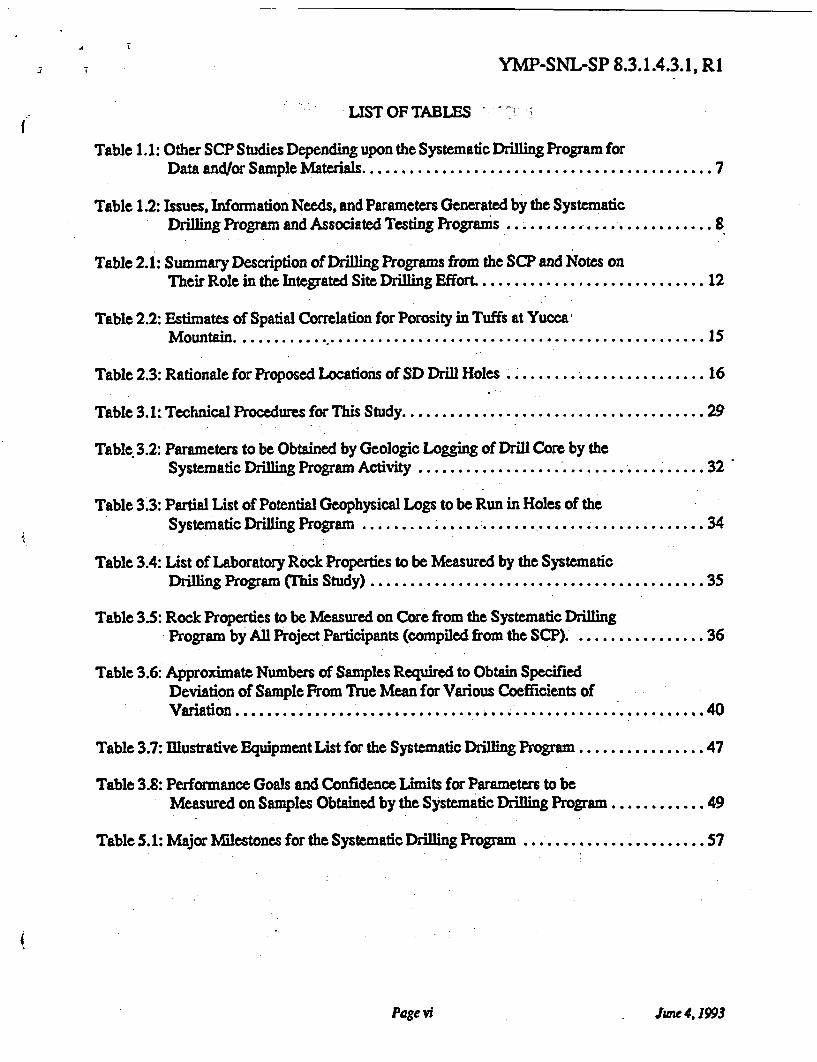
LIST OF TABLES
Table 1.1: Other SCP Studies Depending upon the Systematic Drilling Program forData and/or Sample Materials ............................................ 7
Table 1.2: Issues, Information Needs, and Parameters Generated by the SystematicDrilling Program and Associated Testing Programs .......................... 8
Table 2.1: Summary Description of Drilling Programs from the SCP and Notes onTheir Role in the Integrated Site Drilling Effort ............................. 12
Table 2.2: Estimates of Spatial Correlation for Porosity in Tuffs at YuccaMountain ....................................................... 15
Table 2.3: Rationale for Proposed Locations of SD Drill Holes ........ ................... 16
Table 3.1: Technical Procedures for ThisStudy ...................................... 29
Table 3.2: Parameters to be Obtained by Geologic Logging of Drill Core by theSystematic Drilling Program Activity ...................................... 32
Table 3.3: Partial List of Potential Geophysical Logs to be Run in Holes of theSystematic Drilling Program ............... .............................. 34
Table 3.4: List of Laboratory Rock Properties to be Measured by the SystematicDrilling Program This Study) .......................................... 35
Table 3.5: Rock Properties to be Measured on Core from the Systematic DrillingProgram by All Project Participants (compiled from the SCP). ................ 36
Table 3.6: Approximate Numbers of Samples Required to Obtain SpecifiedDeviation of Sample From True Mean for Various Coefficients ofVariation ....................................................... 40
Table 3.7: Illustrative Equipment List for the Systematic Drilling Program ................ 47
Table 3.8: Performance Goals and Confidence Limits for Parameters to beMeasured on Samples Obtained by the Systematic Drilling Program ............ 49
Table 5.1: Major Milestones for the Systematic Drilling Program ....................... 57
Page vi June 4, 1993
YMP-SNL-SP 8.3.1.4.3.1, R1
1.0 PURPOSE AND OBJECTIVES OF THE STUDY
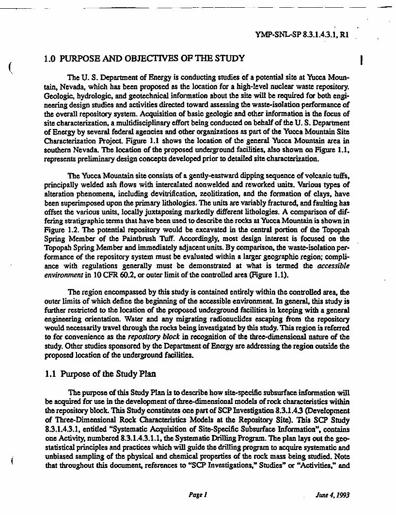
The U. S. Department of Energy is conducting studies of a potential site at Yucca Moun-tain, Nevada, which has been proposed as the location for a high-level nuclear waste repository.Geologic, hydrologic, and geotechnical information about the site will be required for both engi-neering design studies and activities directed toward assessing the waste-isolation performance ofthe overall repository system. Acquisition of basic geologic and other information is the focus ofsite characterization, a multidisciplinary effort being conducted on behalf of the U. S. Departmentof Energy by several federal agencies and other organizations as part of the Yucca Mountain SiteCharacterization Project. Figure 1.1 shows the location of the general Yucca Mountain area insouthern Nevada. The location of the proposed underground facilities, also shown on Figure 1.1,represents preliminary design concepts developed prior to detailed site characterization.
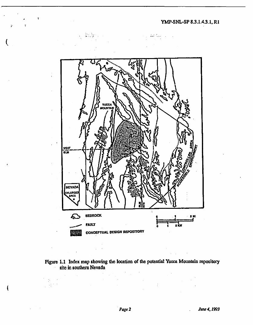
The Yucca Mountain site consists of a gently-eastward dipping sequence of volcanic tuffs,principally welded ash flows with intercalated nonwelded and reworked units. Various types ofalteration phenomena, including devitrification, zeolitization, and the formation of clays, havebeen superimposed upon the primary lithologies. The units are variably fractured, and faulting hasoffset the various units, locally juxtaposing markedly different lithologies. A comparison of dif-fering stratigraphic terms that have been used to describe the rocks at Yucca Mountain is shown inFigure 1.2. The potential repository would be excavated in the central portion of the TopopahSpring Member of the Paintbrush Tuff. Accordingly, most design interest is focused on theTopopah Spring Member and immediately adjacent units. By comparison, the waste-isolation per-formance of the repository system must be evaluated within a larger geographic region; compli-ance with regulations generally must be demonstrated at what is termed the accessibleenvironment in 10 CFR 60.2, or outer limit of the controlled area (Figure 1.1).
The region encompassed by this study is contained entirely within the controlled area, theouter limits of which define the beginning of the accessible environment. In general, this study isfurther restricted to the location of the proposed underground facilities in keeping with a generalengineering orientation. Water and any migrating radionuclides escaping from the repositorywould necessarily travel through the rocks being investigated by this study. This region is referredto for convenience as the repository block in recognition of the three-dimensional nature of thestudy. Other studies sponsored by the Department of Energy are addressing the region outside theproposed location of the underground facilities.
1.1 Purpose of the Study Plan
The purpose of this Study Plan is to describe how site-specific subsurface information willbe acquired for use in the development of three-dimensional models of rock characteristics withinthe repository block. This Study constitutes one part of SCP Investigation 8.3.1.4.3 (Developmentof Three-Dimensional Rock Characteristics Models at the Repository Site). This SCP Study8.3.1.4.3.1, entitled "Systematic Acquisition of Site-Specific Subsurface Information", containsone Activity, numbered 8.3.1.43.1.1, the Systematic Drilling Program. The plan lays out the geo-statistical principles and practices which will guide the drilling program to acquire systematic andunbiased sampling of the physical and chemical properties of the rock mass being studied. Notethat throughout this document, references to "SCP Investigations," Studies" or "Activities," and
Page I
YMP 8.3.1.4.3.1, R1
Figure 1.1 Index map showing the location of the potential Yucca Mountain repository
site in southern Nevada
Page 2 June 4,1993
YMP-SNL-SP 8.3.1.4.3.1, R1
Formal Geologic Microstratigraphic Thermal/MechanicalStratigraphy Units Units
Figure 1.2 Comparative stratigraphic terminology in common usage at Yucca Mountain.modified after Scott and Bonk (1984) for the immediate repository vicinity; fromOrtiz and others, 1985. Thicknesses and "weathering profile" are highly sche-matic; character varies with location.
Page 3 June 4, 1993
YMP-SNL-SP 8.3.1.4.3.1, R1
the associated numeric strings refer to the Yucca Mountain Site Characterization Plan (DOE,1988a). The Site Characterization Plan describes the regulatory and general technical rationale forthe complete site characterization program, and it provides insight into the integration of the vari-ous activities into a comprehensive understanding of the Yucca Mountain site.
This Study is unusual in its statistical and geographic focus. Many other studies focus onevaluating phenomena or processes, in order to provide regulatory assurance that these phenom-ena and processes are adequately understood. By contrast, this study has a unique areal focus cen-tered on the conceptual-design underground facilities, and it seeks to provide assurance that avariety of geologic and other parameters are adequately represented in a geostatistical sense bysamples and descriptions taken in the immediate location of the potential repository. This repre-sentativeness will help assure adequate assessment of the performance of the site, given under-standing of the processes evaluated in other studies.
The emphasis of this study on the "site" provides a useful and necessary unifying frame-work for integrating a multidisciplinary engineering study such as the Yucca Mountain Project.Understanding the importance of this study to the overall site characterization program and thereasons for implementing the study in the manner described in this document is only possible bydescribing the work in its overall context. Throughout this Study Plan, an effort is made todescribe (1) the work to be conducted directly under this Study Plan and (2) work conducted byother SCP studies that is directly allied with the objectives of the higher-level investigation ofwhich this study is a part. The level of detail provided for item (1) is necessarily significantlygreater than that associated with item (2). Detail regarding the specifics of work conducted byother SCP studies may be found by reference to the appropriate study plans. Discussion of issuesrelated to the integration of this study with other site characterization investigations and individ-ual studies is provided in relevant sections of this Study Plan. An overview of the required inte-gration is given in Section 2.5.
1.2 Objectives of the Study
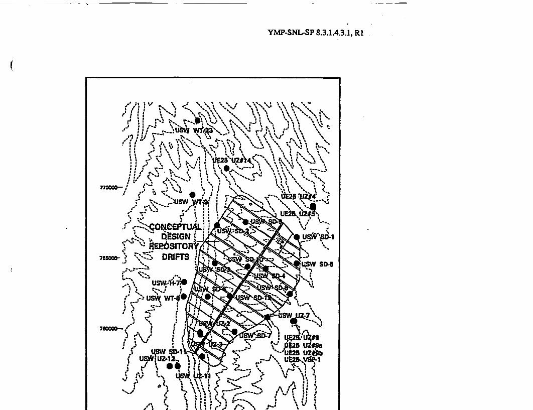
The objective of the Systematic Drilling Program is to provide for the systematic collec-tion of rock samples and the description of the geological and geophysical characteristics of therepository block by drilling at least twelve surface-based drill holes (Section 3.1). The currentlyproposed positions for these holes are shown in Figure 1.3, with the prefix "SD-." Other hole loca-tions shown are part of other SCP Studies. Their locations, and the sampling program for themhave been taken into account in designing the SD hole layout. Together, all holes shown form anintegrated drilling program for the Yucca Mountain Project
Holes of the Systematic Drilling Program will be targeted to a depth of 300 ft (100 m)below the static water level, passing through the repository horizon and sampling it as well as theoverlying and underlying rock units. The intended depth of the holes varies from 1700-2300 ft(500-700 m), and depends primarily upon surface topography with respect to the water table. Therequirement of 300 foot (100 m) below the static water level originates in Section 8.3.5.12 of theSCP (Table 8.3.5.12-3). Selected locations may be drilled to approximately 3,000-ft (900-m)depths in order to provide core samples of deeper units (tentatively SD-I, SD-7, H-7), asrequested by other studies (SCP Study 8.3.1.3.2.1). Holes will be continuously cored, and a suite
Page 4 June4, 1993
YMP-SNL-SP 8.3.1.4.3.1, R1
of geophysical logs (Section 3.3) will be obtained from each hole.
Core from these drill holes will provide the physical materials for description of the sub-surface geology (Section 3.2). The intact core will be examined carefully and logged in detail forgeneral lithologic, structural and other geologic information, and for features important to engi-neering design and performance assessment. The drill core will also provide physical specimensfor laboratory testing of hydrologic, thermal, and mechanical rock properties. Specimens will beanalyzed for mineralogic and geochemical purposes as well. A limited suite of testing for rockproperties of general utility in describing the framework of the site will be performed directly bythis study (Section 3.4); significant additional testing will be performed by other, more specialized(process-oriented) studies as described in later sections. The drill holes themselves will provideaccess to the subsurface environment of Yucca Mountain for potential use by other studies.
In addition to the surface-based activities, this study will collect additional samples andsupporting information in a systematic manner from the underground workings of the ExploratoryStudies Facility (ESF). These samples will be used, as needed, to supplement the description ofspatial continuity patterns in the (stratigraphically) horizontal plane in the two units of principalinterest within the Yucca Mountain Project, namely the Topopah Spring Member of the Paint-brush Tuff (the repository horizon) and the tuffaceous units of Calico Hills (the designated "pri-mary barrier" to waste migration). Samples will be collected as short cores or subcored handspecimens from the ribs of appropriate underground workings, and their location keyed to geo-logic maps produced by other studies (SCP Activity 8.3.1.4.2.2.4). Laboratory testing of thesesamples will be identical to that described in the preceding paragraph.
Finally, the collective results of this study will be evaluated (Section 3.5) on an on-goingbasis to ensure that drilling and sampling are being conducted in an effective manner and that thedata and information are likely to be adequate for performance assessment and design activities.This on-going evaluation may result in changes to the proposed drilling, sampling, and testingprograms - not only for this study, but for relevant aspects of other Project drilling efforts as well.
1.3 Use of Study Plan Results
Taken in context, the Systematic Drilling Program and the testing studies that dependupon it will provide a major portion of the total information and physical sample material fromthe limited volume of rock containing the proposed repository. Holes to be drilled as part of theUnsaturated Zone Percolation Study (83.12.23; "UZ-" prefix in Figure 13) serve an identicalpurpose for rocks in the immediate vicinity (but generally outside) of the repository block. Onlythe Exploratory Studies Facility will provide a similar volume of samples or information fromwithin the repository block, and this material will be restricted to the location of the ESF excava-tions. In this respect, the Systematic Drilling Program - particularly when combined with theholes to be drilled as part of the Unsaturated Zone Percolation Study -may be viewed as provid-ing extensive (areal) coverage, whereas the Exploratory Studies Facility provides intensive detail.
In addition to the descriptive site data that will be generated directly by this study, a signif-icant amount of testing and other data gathering will be conducted by other site characterizationstudies using core samples or the drill holes themselves. A brief description of these studies is pre-
Page 6 June 4,1993
YMP-SNL-SP 8.3.1.4.3.1, R1
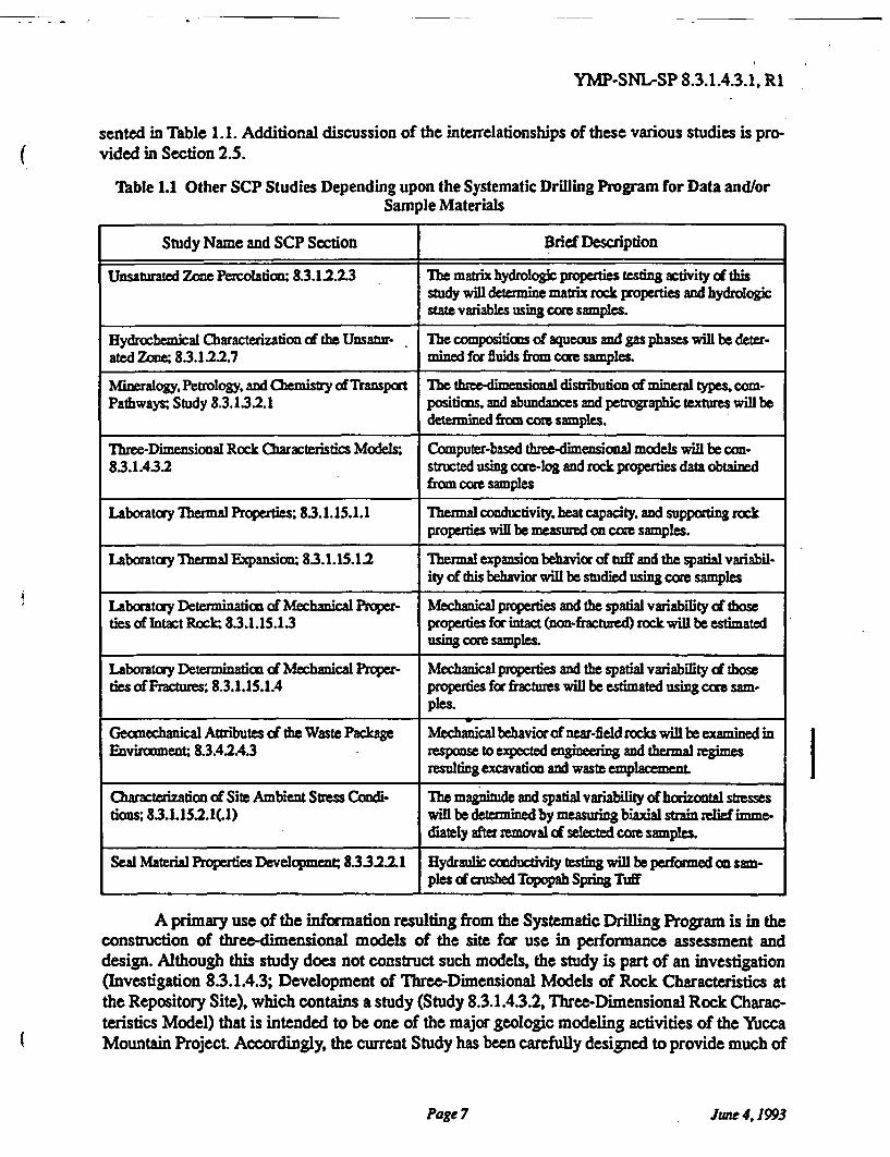
sented in Table l. 1. Additional discussion of the interrelationships of these various studies is pro-vided in Section 2.5.
Table 1.1 Other SCP Studies Depending upon the Systematic Drilling Program for Data and/orSample Materials
Study Name and SCP Section Brief Description
Unsaturated Zone Percolation; 8.3.1 .2.3 The matrix hydrologic properties testing activity of thisstudy will determine matrix rock properties and hydrologicstate variables using core samples.
Hydrochemical Characterization of the Unsatur- The compositions of aqueous and gas phases will be deter-ated Zone; 8.3.1.22.7 mined for fluids from core samples.
Mineralogy, Petrology, and Chemistry of Transport The three-dimensional distribution of mineral types, com-Pathways; Study 8.3.132.1 positions, and abundances and petrographic textures will be
determined from core samples.
Three-Dimensional Rock Characteristics Models; Computer-based three-dimensional models will be con-83.1.432 structed using core-log and rock properties data obtained
from core samples
Laboratory Thermal Properties; 83.1.15.1.1 Thermal conductivity, heat capacity, and supporting rockproperties will be measured an core samples.
Laboratory Thermal Expansion 83.1.15.12 Thermal expansion behavior of tuff and the spatial variabil-ity of this behavior will be studied using core samples
Laboratory Determination of Mechanical Proper- Mechanical properties and the spatial variability of thoseties of Intact Rock; 8.3.1.15.13 properties for intact (non-fractured) rock will be estimated
using core samples.
Laboratory Determination of Mechanical Proper- Mechanical properties and the spatial variability of thoseties of Fractures; 8.3.1.15.1.4 properties for fractures will be estimated using core sam-
ples.
Geomechanical Attributes of the Waste Package Mechanical behavior of near-field rocks will be examined inEnvironment; 8.3.4.4.3 response to expected engineering and thermal regimes
resulting excavation and waste emplacement
Characterization of Site Ambient Stress Condi- The magnitude and spatial variability of horizontal stressestions; 83.1.15.2.1(.l) will be determined by measuring biaxial strain relief imme-
diately after removal of selected core samples.
Seal Material Properties Development; 8.332.11 Hydraulic conductivity testing will be performed on sam-ples of crushed Topopah Spring Tuff
A primary use of the information resulting from the Systematic Drilling Program is in theconstruction of three-dimensional models of the site for use in performance assessment anddesign. Although this study does not construct such models, the study is part of an investigation(Investigation 8.3.1.4.3; Development of Three-Dimensional Models of Rock Characteristics atthe Repository Site), which contains a study (Study 8.3.1.4.3.2, Three-Dimensional Rock Charac-teristics Model) that is intended to be one of the major geologic modeling activities of the YuccaMountain Project. Accordingly, the current Study has been carefully designed to provide much of
Page 7 June 4,1993
YMP-SNL-SP 8.3.1.4.3.1, R1
the information needed to model the immediate repository block, The need for site-specific infor-mation reflects this close linkage to the parallel modeling activity. Modeling of the Yucca Moun-tain site necessarily will need to include data and information from a variety of sources includingsurface mapping, geophysical investigations, and underground testing, in addition to the informa-tion from this study.
Rock characteristics models are not an end in themselves. These models are to be used inperformance assessment and design activities that are directed toward licensing documents. Thus,the information to be gathered by the Systematic Drilling Program will be used by a large numberof Project participants outside the site program, per se. Because the use of this information bydesign engineers and performance analysts will be so widespread, it is not easy to compile a tabu-lar listing similar to Table 1.1, which refers only to site studies listed in Chapter 8 of the SCRThese performance assessment and design uses are more easily described by reference to designand performance "issues" and "information needs," as is done in the following section (Section1.4.1).
1.4 Regulatory Rationale and Justification for the Information to be Collected
1.4.1 Resolution of Performance and Design Issues
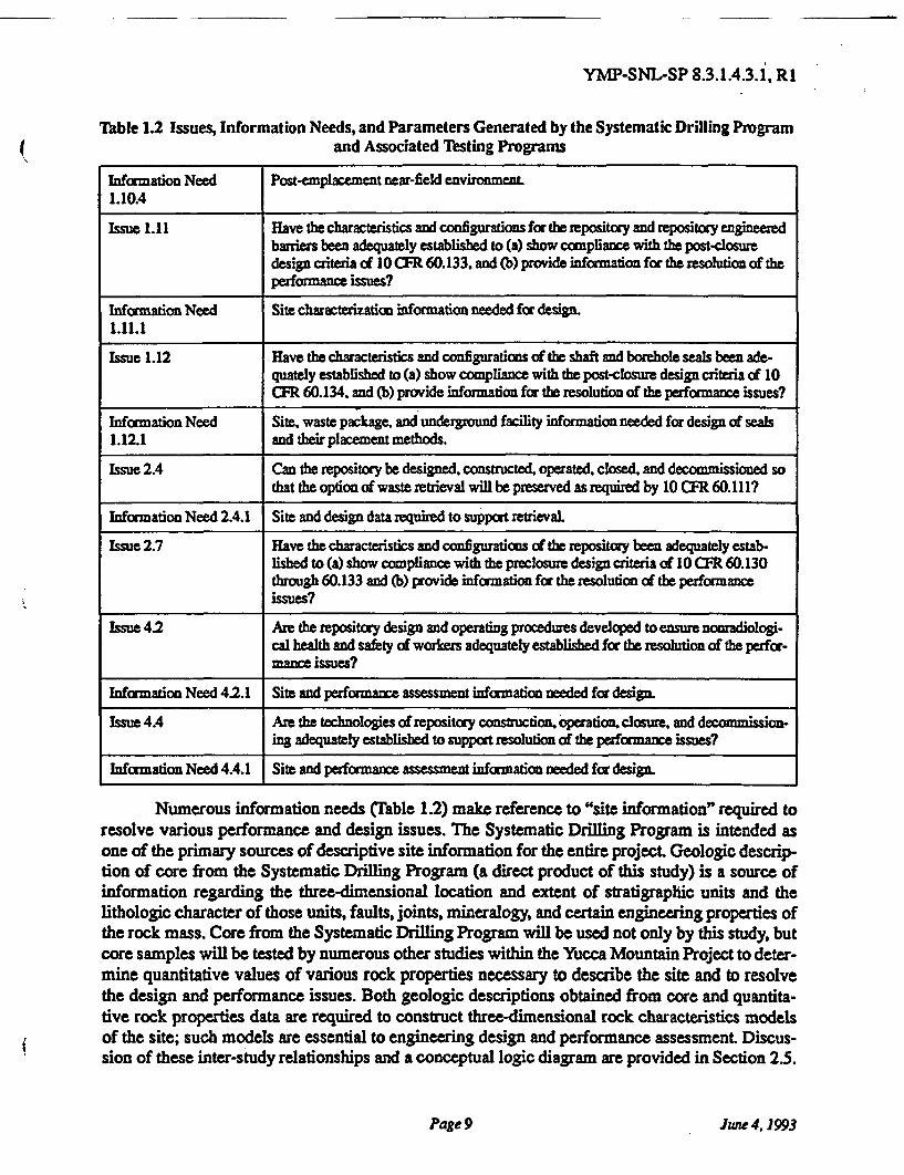
The performance allocation process has been used by the Yucca Mountain Project toestablish appropriate issue resolution strategies. A general discussion of the performance alloca-tion process is provided in SCP Section 8.1, and the issues to be resolved are described in SCPSection 8.2.1. Issue resolution strategies and details of performance allocation for each design andperformance assessment issue are summarized in SCP Section 8.2 and provided in full detail inSCP Sections 83.2 through 8.3.5. The principal performance assessment and design issues, andcorresponding information needs, that will be addressed using the information and data obtainedin this study are summarized in Table 1.2.
Table 1.2 Issues, Information Needs, and Parameters Generated by the Systematic Drilling Programand Associated Testing Programs
Issue 1.1 Will the mined geologic disposal system meet the system performance objectives forlimiting radionuclide releases to the accessible environment as required by 10 CFR60.112 and 40 CFR 191.13?
Infomation Need 1.1.1 Site information needed to calculate releases to the accessibe environment.
Issue 1.6 Will the site meet the performance objective for pre-waste emplacement ground-watertravel time as required by 10 CFR 60.1137
Infomation Need 1.6.1 Site information and design concepts needed to identify the fastest path of likely radio-nudlide travel and to calculate the ground-water travel time along that path.
Issue 1.8 Can the demonstrations for favorable and potentially adverse conditions be made asrequired by 10 CFR 60.122?
Issue 1.10 Have the characteristics and configuration of the waste packages been adequatelyestablish to (a) show compliance with the post-closure design criteria of 10 CFR60.135, and (b) provide information for the resolution of the performance issues?
Page 8 June 4,1993
YMP-SNL-SP 8.3.1.4.3.1, R1
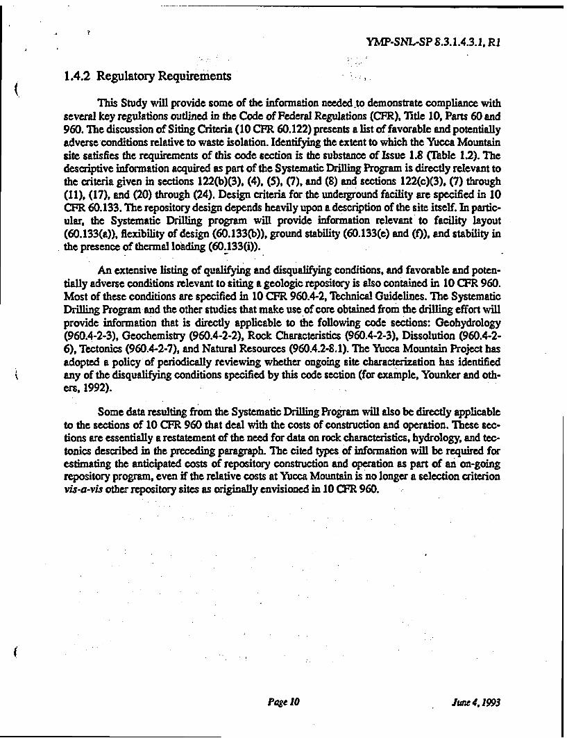
Table 1.2 Issues, Information Needs, and Parameters Generated by the Systematic Drilling Programand Associated Testing Programs
Information Need Post-emplacement near-field environment1.10.4
issue 1.11 Have the characteristics and configurations for the repository and repository engineeredbarriers been adequately established to (a) show compliance with the post-closure
design criteria of 10 CFR 60.133, and (b) provide information for the resolution of the
performance issues?
Information Need Site characterization information needed for design.1.11.1
Issue 1.12 Have the characteristics and configurations of the shaft and borehole seals been ade-quately established to (a) show compliance with the post-closure design criteria of 10CFR 60.134. and (b) provide information for the resolution of the performance issues?
Information Need Site, waste package. and underground facility information needed for design of seals1.12.1 and their placement methods.
Issue 2.4 Can the repository be designed, constructed. operated, closed, and decommissioned sothat the option of waste retrieval will be preserved as required by 10 CFR 60.111?
Information Need 24.1 Site and design data required to support retrieval.
Issue 2.7 Have the characteristics and configurations of the repository been adequately estab-lished to (a) show compliance with the preclosure design criteria of 10 CFR 60.130through 60.133 and (b) provide information for the resolution of the performanceissues?
Issue 4.2 Are the repository design and operating procedures developed to ensure nonradiologi-cal health and safety of workers adequately established for the resolution of the perfor-mance issues?
Information Need 4.2.1 Site and performance assessment information needed for design.
Issue 4A Are the technologies of repository construction, operation, closure, and decommission-ing adequately established to support resolution of the performance issues?
Information Need 44.1 Site and performance assessment information needed for design.
Numerous information needs (Table 1.2) make reference to "site information" required toresolve various performance and design issues. The Systematic Drilling Program is intended asone of the primary sources of descriptive site information for the entire project. Geologic descrip-tion of core from the Systematic Drilling Program (a direct product of this study) is a source ofinformation regarding the three-dimensional location and extent of stratigraphic units and thelithologic character of those units, faults, joints, mineralogy, and certain engineering properties ofthe rock mass. Core from the Systematic Drilling Program will be used not only by this study, butcore samples will be tested by numerous other studies within the Yucca Mountain Project to deter-mine quantitative values of various rock properties necessary to describe the site and to resolvethe design and performance issues. Both geologic descriptions obtained from core and quantita-tive rock properties data are required to construct three-dimensional rock characteristics modelsof the site; such models are essential to engineering design and performance assessment Discus-sion of these inter-study relationships and a conceptual logic diagram are provided in Section 25.
Page 9 June 4, 1993
YMP-SNL-SP 8.3.1.4.3.1, R1
1.4.2 Regulatory Requirements
This Study will provide some of the information needed to demonstrate compliance withseveral key regulations outlined in the Code of Federal Regulations (CFR), Title 10, Parts 60 and960. The discussion of Siting Criteria (10 CFR 60.122) presents a list of favorable and potentiallyadverse conditions relative to waste isolation. Identifying the extent to which the Yucca Mountainsite satisfies the requirements of this code section is the substance of Issue 1.8 (Table 1.2). Thedescriptive information acquired as part of the Systematic Drilling Program is directly relevant tothe criteria given in sections 122(b)(3), (4), (5), (7), and (8) and sections 122(c)(3), (7) through(11), (17), and (20) through (24). Design criteria for the underground facility are specified in 10CFR 60.133. The repository design depends heavily upon a description of the site itself. In partic-ular, the Systematic Drilling program will provide information relevant to facility layout(60.133(a)), flexibility of design (60.133(b)), ground stability (60.133(e) and (f)), and stability inthe presence of thermal loading (60.133(i)).
An extensive listing of qualifying and disqualifying conditions, and favorable and poten-tially adverse conditions relevant to siting a geologic repository is also contained in 10 CFR 960.Most of these conditions are specified in 10 CPR 960.4-2, Technical Guidelines. The SystematicDrilling Program and the other studies that make use of core obtained from the drilling effort willprovide information that is directly applicable to the following code sections: Geohydrology(960.4-2-3), Geochemistry (960.4-2-2), Rock Characteristics (960.4-2-3), Dissolution (960.4-2-6), Tectonics (960.4-2-7), and Natural Resources (960.4.2-8.1). The Yucca Mountain Project hasadopted a policy of periodically reviewing whether ongoing site characterization has identifiedany of the disqualifying conditions specified by this code section (for example, Younker and oth-ers, 1992).
Some data resulting from the Systematic Drilling Program will also be directly applicableto the sections of 10 CFR 960 that deal with the costs of construction and operation. These sec-tions are essentially a restatement of the need for data on rock characteristics, hydrology, and tec-tonics described in the preceding paragraph. The cited types of information will be required forestimating the anticipated costs of repository construction and operation as part of an on-goingrepository program, even if the relative costs at Yucca Mountain is no longer a selection criterionvis-a-vis other repository sites as originally envisioned in 10 CFR 960.
Page 10 June 4,1993
YMP-SNL-SP 8.3.1.4.3.1, R1
2.0 RATIONALE FOR THE SYSTEMATIC DRILLING PROGRAM STUDY
2.1 Technical Rationale and Justification
2.1.1 General Rationale for the Site Drilling Effort
The geology and rock characteristics of the repository block may be inferred from numer-ous existing, pre-site characterization sources of information: surface geologic mapping, analysisof geologic cross sections, sparse existing drill holes, and similar sources. However, these data arenot sufficient to develop the detail -- and the confidence in that detail - that is required for alicense application. Additional characterization is required through drilling and sampling of therepository block itself.
McBratney and Webster (1983, p. 178) refer to numerous other studies that have con-cluded that "systematic sampling, i.e., at regular intervals, along a transect or on a grid, [gives] themost precise estimates [of a variable of interest] for a given effort." Systematic, gridded drillingpatterns are widely accepted as the standard method of site characterization in mining applica-tions. Journel (1983) and Deutsch (1989) discuss preferential sampling patterns in the earth sci-ences and the consequences of such non-systematic sampling when estimating spatial averages ordistributions of values. Such non-systematic sampling commonly occurs as a result of the need tocharacterize specific, recognized features of a site, especially to identify and characterize poten-tially adverse or disqualifying features that might be present (for example, 10 CFR 960.4-2). Forexample, drill holes UZ-11 and UZ-12 (Figure 1.3) are paired holes to be drilled for cross-holehydrologic testing on opposite sides of the Solitario Canyon fault. Other non-systematic samplingmay occur as a consequence of drilling conducted to evaluate processes operative in the siteregion in order to understand site performance. The program of work described in the SCPattempts to improve the state of knowledge by developing a systematic, yet integrated, drillingprogram for site characterization.
Prior characterization of the Yucca Mountain site consisted of a program of features-ori-ented sampling, focused primarily on determining the preliminary ability of the site to meet thelicensing requirements. The program did not attempt to provide the systematic description of thesite properties needed for design and performance assessment. Design and performance assess-ment need to evaluate the heterogeneity of rock characteristics and the effect of such heterogene-ity on performance. Systematic and unbiased data, such as will be acquired by this Study, arerequired for these performance-related analyses.
The integrated drilling effort capitalizes upon the need for continuing investigation of var-ious features and processes critical to evaluation of the site (for example, faults as preferentialpathways, unexpected perched water zones, etc.). The UZ- and WT- holes shown in Figure 1.3 aregood examples of the continuing feature-of-interest approach. The feature- and process-orienteddrill holes planned by other studies have been combined with the holes proposed as part of theSystematic Drilling Program so that statistical benefits are gained from the pattern of coverage.The combined pattern of coverage consists of a partial grid covering the immediate repositoryblock, which achieves systematic sampling without the additional drilling that would be requiredif all activities were conducted in isolation. Although any drilling may identify new feature which
Page 11 June 4,1993
YMP-SNL-SP 8.3.1.4.3.1. R1
require additional drilling, the Systematic Drilling Program is primarily intended to acquire sys-tematic description of design and performance assessment characteristics in the vicinity of therepository excavations, with principal responsibility for identifying additional "features" of inter-est remaining with the studies focused on those particular topics.
A general discussion of how the overall drilling program will be integrated is contained insection 8.3.1.4.1 of the SCP. A description of how specific other drilling efforts mesh with and,provide additional information to the Systematic Drilling Program is provided in Table 2.1. Addi-tional details of the mechanics of each project drilling program can be found in the Surface-BasedInvestigations Plan (DOE, 1988b).
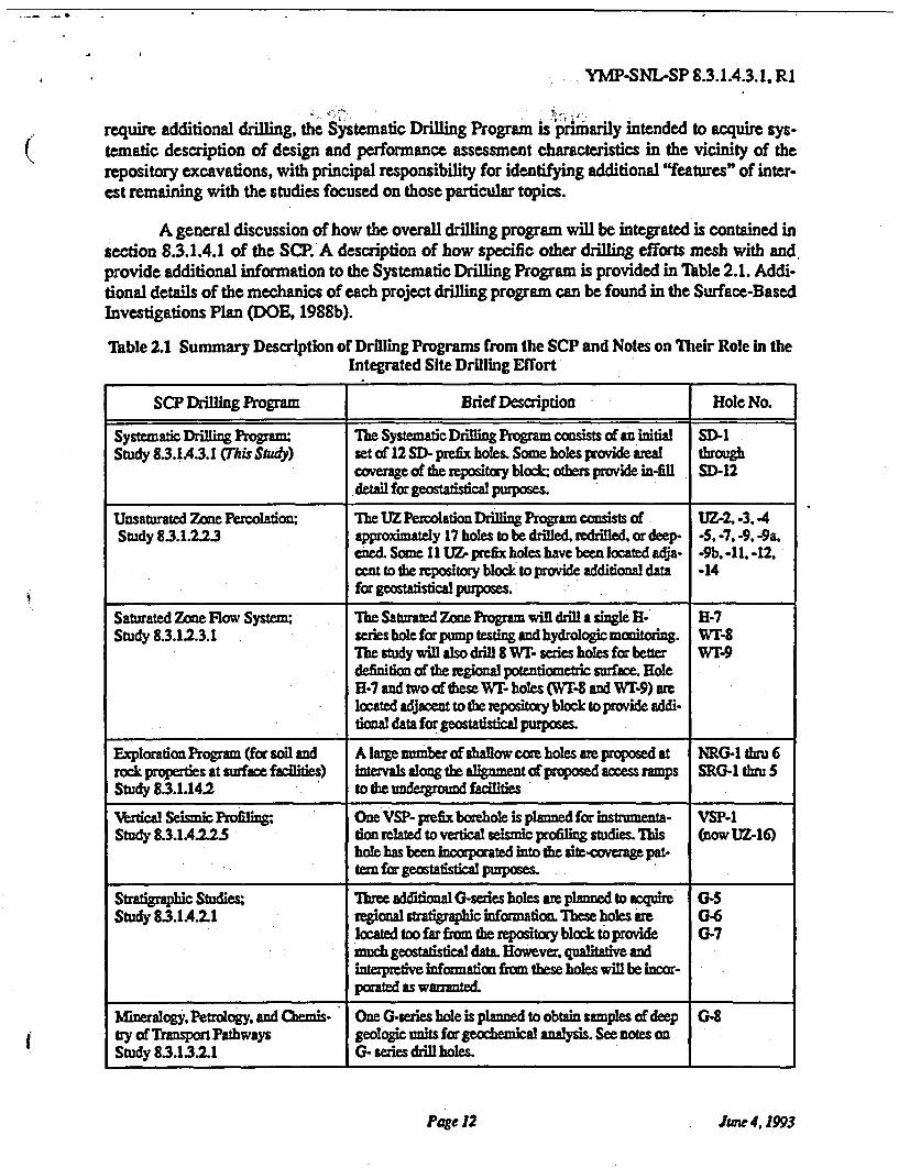
Table 2.1 Summary Description of Drilling Programs from the SCP and Notes on Their Role in theIntegrated Site Drilling Effort
SCP Drilling Program Brief Description Hole No.
Systematic Drilling Program: The Systematic Drilling Program consists of an initial SD-1Study 83.143.1 (This Study) set of 12 SD- prefix holes. Some holes provide areal though
coverage of the repository block; others provide in-fill SD-12detail for geostatistical purposes.
Unsaturated Zone Percolation; The UZ Peolation Drilling Program consists of UZ-2, -3. 4Study 8.3.1.2.2.3 approximately 17 holes to be drilled, redrilled, or deep- -5, -7, -9, -9a.
ened. Some 11 UZ- prefix holes have been located adja- -9b. -11. -12,cent to the repository block to provide additional data -14
for geostatistical purposes._
Saturated Zone Flow System; The Saturated Zone Program will drill a single H- H-7Study 8.3.1.2.3.1 series hole for pump testing and hydrologic monitoring. WT-8
The study will also drill 8 WI series holes for better WT-9definition of the regional potentiometric surface. HoleH-7 and two of these WT- holes (WT-8 and WT-9) are
located adjacent to the repository block to provide addi-tional data for geostatistical purposes.
Exploration Program (for soil and A large number of shallow core holes are proposed at NRG-1 tru 6rock properties at surface facilities) intervals along the alignment of proposed ramps SRG-l thru 5Study 8.3.1.142 to the underground facilities
Vertical Seismic Profiling One VSP- prefix borehole is planned for instrumenta- VSP-1Study 8.3.1A.2.25 tion related to vertical seismic profiling studies.This (nowUZ-16)
hole has been incorporated into the site-coverage pat-tern for geostatistical purposes.
Stratigraphic Studies; Three additional G-series holes are planned to acquire, G-5Study 8.3.l4.21 regional stratigraphic information. These holes are G-6
located too far from the repository block to provide G-7much geostatistical data. However. qualitative andinterpretive information from these holes will be incor-porated as warranted
Mineralogy, Petrology, and Chemis- One G-series hole is planned to obtain samples of deep G-8try of Transport Pathways geologic units for geochemical analysis. See notes onStudy 8.3.13.1 G- series drill holes.
Page 12 June4,1993
YMP-SNL-SP 8.3.1.4.3.1, R1
Table 2.1 Summary Description of Drilling Programs from the SCP and Notes on Their Role in theIntegrated Site Drilling Effort
SCP Drilling Program Brief Description Hole No.
Characterization of Volcanic Features Four V- holes are planned to investigate four aeromag- V-1.Study 8.3.1.8.5.1 netic anomalies that may represent buried volcanic or V-2.
intrusive features to the west of the site. See notes on V-3.G- series drill holes. V-4
2.1.2 Proposed Approach to the Study
This Study proposes to drill a suite of core holes, described below, to provide areal cover-age of the repository block and immediately adjacent regions. Geologic and engineering informa-tion will be obtained by logging the core from these holes. Geophysical logging of the drill holeswill provide additional geologic information and independent confirmation of the geologicdescriptions of the repository site. These activities will provide a large portion of the "site infor-mation" referred to in the various issues and information needs listed in Table 1.2. Specific"parameters" or rock characteristics to be measured and/or described as part of this work are dis-cussed in greater detail in Section 3 of this Study Plan.
In addition to the descriptive geologic and engineering information to be obtained by coredescription or measurements taken from the core as a whole, this study will also obtain a set oflaboratory measurements of rock properties on samples taken from the core. These laboratoryrock characteristics consist of basic matrix properties of the rock mass and in situ conditions,which would otherwise deteriorate, that are essential to a first-order understanding of the site.These rock properties are sometimes referred to as "framework properties" elsewhere in thisStudy Plan. Specific properties to be measured are discussed in greater detail in Section 3 of thisStudy Plan (see also Table 3.4). Laboratory properties will be measured on the same physicalspecimen, whenever feasible, to allow direct inter-variable correlations of rock properties. Theinterrelationship of material-properties testing to be conducted as part of this study to similarmaterial-properties testing to be conducted as part of other, process-oriented SCP studies (seeSection 1.1) is discussed at greater length below in Section 2.5.
Supplemental samples will also be collected from appropriate underground workings ofthe Exploratory Studies Facility and subjected to the same laboratory testing procedures describedin the preceding paragraph. This aspect of the sampling and testing effort described in this StudyPlan is secondary to the main portion of the work, which consists of the surface-based portion ofthe Systematic Drilling Program activity. The scope of the proposed Exploratory Studies Facilityhas expanded significantly since development of the SCP (DOE, 1988a). The extensive networkof underground drifting in both the repository horizon itself (Topopah Spring Member) and theprimary barrier to waste migration (tuffs of Calico Hills) provides an excellent opportunity for the"systematic acquisition of site-specific subsurface information" (title of this study) that was notcontemplated during development of the SCP
This Study Plan explicitly holds that the rock properties of interest to the Yucca MountainProject are spatially correlated, and thus rock samples do not represent independent samples from
Page 13 June 4,1993
YMP-SNL-SP 8.3.1.4.3. 1, R1
some statistical population. This proposition, which is well supported by preliminary scopingstudies conducted at the Yucca Mountain Site and by general geologic knowledge (see Section2.1.3), renders many classical statistical methods for determining the number of samples requiredfor characterization unusable or of questionable applicability. Additionally, discussion of sam-pling strategy is complicated by the need to characterize geologic materials that potentially maybe considered to represent many different and non-exclusive "populations." Each of the strati-graphic entities described in Figure 1.2 could represent a different population for some purposes.Unquestionably, other populations could be defined as well. A general utility program of drillingand sampling, such as this study, must necessarily be a compromise among the requirements sug-gested by many diverse users of the final data. Discussion of the rationale for the proposed num-bers of drill holes and down hole samples is presented in Section 2.2. Some of the variousstatistical techniques and methods that have been used to develop these current plans, and whichwill be used as the Study progresses to confirm or revise those plans, are described in Section 3.5.
2.13 Scoping Studies
A number of scoping studies have defined spatial correlation structure in Yucca Mountaintuffs using systematic sampling transects and grids covering selected accessible outcrops of YuccaMountain tuffs (Istok and others, 1991, Rautman, 1991; Rautman and others, 1991; Rautman andFlint, 1992). Geostatistical evaluation of hydrologic properties (Rautman and Flint, 1992) providevaluable planning information for this activity and for other sampling programs. Scoping studiesalso serve as prototyping efforts to test and refine procedures prior to the conduct of quality affect-ing work.
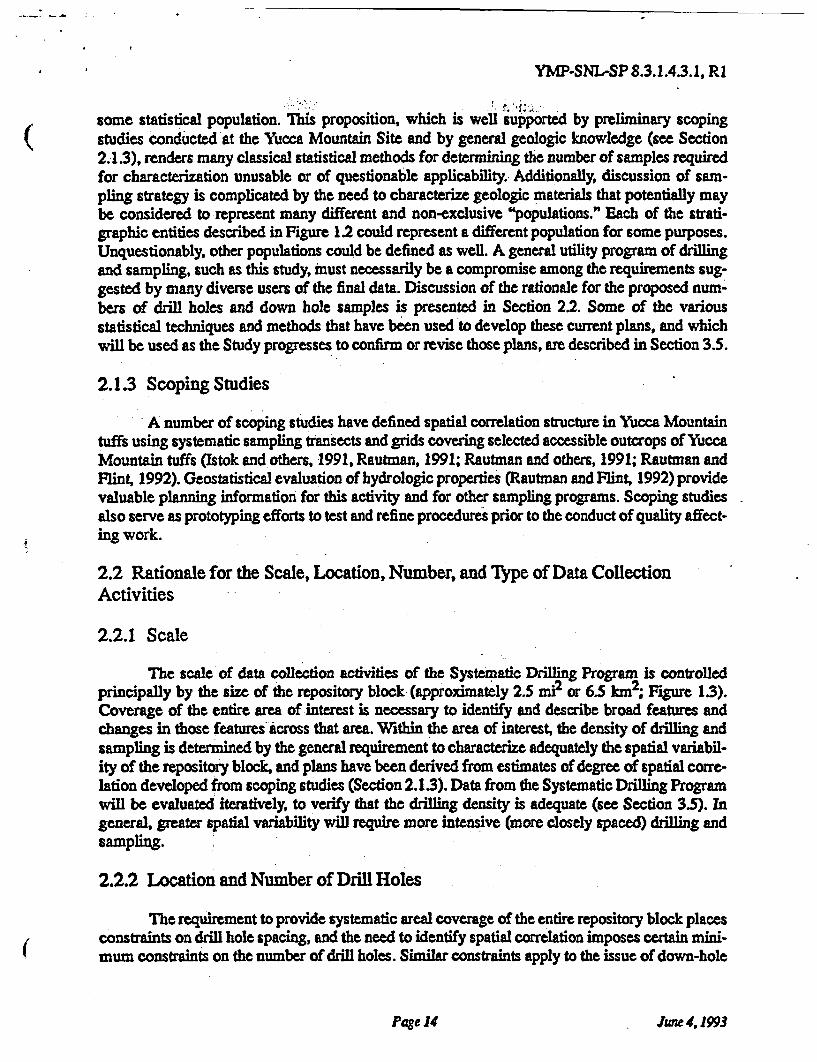
2.2 Rationale for the Scale, Location, Number, and Type of Data CollectionActivities
2.2.1 Scale
The scale of data collection activities of the Systematic Drilling Program is controlledprincipally by the size of the repository block (approximately 2.5 mi2 or 6.5 km2; Figure 1.3).Coverage of the entire area of interest is necessary to identify and describe broad features andchanges in those features across that area. Within the area of interest, the density of drilling andsampling is determined by the general requirement to characterize adequately the spatial variabil-ity of the repository block, and plans have been derived from estimates of degree of spatial corre-lation developed from scoping studies (Section 2.13). Data from the Systematic Drilling Programwill be evaluated iteratively, to verify that the drilling density is adequate (see Section 3.5). Ingeneral, greater spatial variability will require more intensive (more closely spaced) drilling andsampling.
2.2.2 Location and Number of Drill Holes
The requirement to provide systematic areal coverage of the entire repository block placesconstraints on drill hole spacing, and the need to identify spatial correlation imposes certain mini-mum constraints on the number of drill holes. Similar constraints apply to the issue of down-hole
Page 14 June 4,1993
YMP-SNL-SP 8.3.1.4.3.1, R1
sampling patterns (see also Section 2.2.3).
Ideally, the characterization of spatial variability proceeds in stages (Yfantis and others1987), beginning with systematic exploratory sampling on a close-order basis in one or more sub-fields of interest. Once the approximate spatial structure of the rock property of interest is esti-mated, that information is used to design a systematic sampling effort to cover the entire field ofinterest. A triangular grid may be most efficient for site characterization under many circum-stances and such a grid may give the most reliable estimate of the spatial structure. McBratneyand Webster (1983) also support the use of a triangular grid, unless the spatial structure is aniso-tropic, in which case the use of a rectangular grid oriented with long intervals aligned in the direc-tion of least rapid variation is recommended. The practice of focusing sampling efforts acrossgeologic structure has been standard in the mining industry for many years.
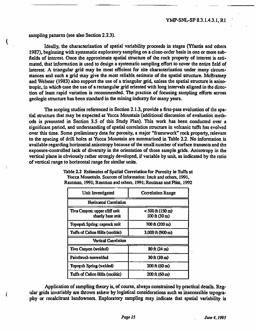
The scoping studies referenced in Section 2.13, provide a first-pass evaluation of the spa-tial structure that may be expected at Yucca Mountain (additional discussion of evaluation meth-ods is presented in Section 3.5 of this Study Plan). This work has been conducted over asignificant period, and understanding of spatial correlation structure in volcanic tuffs has evolvedover this time. Some preliminary data for porosity, a major "framework" rock property, relevantto the spacing of drill holes at Yucca Mountain are summarized in Table 2.2. No information isavailable regarding horizontal anisotropy because of the small number of surface transects and theexposure-controlled lack of diversity in the orientation of those sample grids. Anisotropy in thevertical plane is obviously rather strongly developed, if variable by unit, as indicated by the ratioof vertical range to horizontal range for similar units.
Table 2.2 Estimates of Spatial Correlation for Porosity in Tuffs atYucca Mountain. Sources of information: Istok and others, 1991,
Rautman, 1991; Rautman and others, 1991; Rautman and Flint, 1992
Unit Investigated Correlation Range
Horizontal Correlation
Tiva Canyon: upper cliff unit < 500 ft (150 m)shady base unit 100 ft (30 m)
Topopah Spring: caprock unit 700 ft (200 m)
Tuffs of Calico Hills (zeoltic) 3.000 ft (900 m)
Vertical Correlation
Tiva Canyon (welded) 80 ft (24 m)
Paintbrush nonwelded 30 ft (10 m)
Topopah Spring (welded) 200 ft (60 m)
Tuffs of Calico Hills (zeolitic) 200 ft (60 m)
Application of sampling theory is, of course, always constrained by practical details. Reg-ular grids invariably are thrown askew by logistical considerations such as inaccessible topogra-phy or recalcitrant landowners. Exploratory sampling may indicate that spatial variability is
Page 15 June 4, 1993
YMP-SNL-SP 8.3.1.4.3.1, R1
greater than initially suspected, requiring more detailed sampling. Certain sampling locations maybe fixed by preexisting or externally determined considerations. In the present instance of YuccaMountain, there is an additional perceived need to limit the number of penetrations of the site tothe extent practical and to restrict penetrations to locations compatible with preliminary under-ground facilities design. It is uncertain what, if any, bias is introduced into the resulting data bythese departures from a completely regular grid. The potential for bias will be addressed throughthe statistical (geostatistical) evaluation. Additionally, the iterative nature of the Systematic Drill-ing Program (see Figure 2.2) will allow actions to correct any identified biases during the course
of the drilling activities.
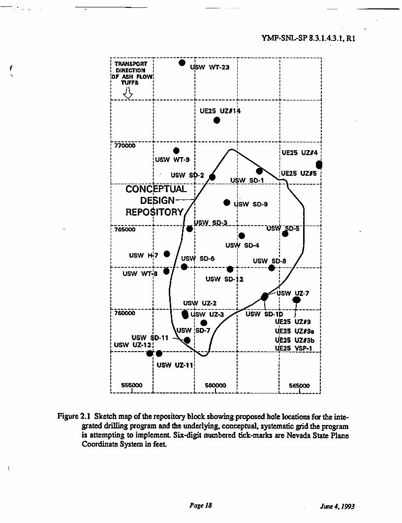
The approach of the integrated drilling program, of which the Systematic Drilling Pro-gram is only a part, is to provide holes located on a semi-regular, rectangular grid (Figure 2.1)covering the entire area of interest. Merging of hole locations for the Systematic Drilling Programwith hole locations fixed by other requirements (principally holes to be drilled by other studies forspecific purposes) cause deviations from regularity. Additional irregularities result from logisticalconstraints, principally surface topography and the need to drill holes within proposed pillar loca-tions in the underground facilities. These requirements combined with the results of scoping stud-ies (Section 2.1.3; Table 2.2) have resulted in changes from the preliminary pattern shown in SCPFigure 8.3.1.4-11. All drill hole locations referred to in this Study Plan are preliminary and aresubject to change as the site characterization program progresses.
Initial coverage of the entire site is at a nominal spacing of 2,500 to 3,000 ft (750 to 900m). Because of the nominal hole spacing, essentially all locations within the repository block willbe within about 1,500 ft (500 m) of a sampled location. The rationale for each SD- hole is pre-sented in Table 2.3. The first phase of drilling will only partially complete the grid intersections(Figure 2.1). This relatively wide-spaced drilling pattern will at least provide areal coverage of theentire repository block. Areal coverage is essential to identify major trends, or systematicchanges, in rock properties across the repository region. An additional aspect to areal coverage isthe need, in an engineering-geology project such as the Yucca Mountain Project, to locate severaldrill holes within a given fault block to facilitate proper geometric modeling of tilted and offsetstratigraphic units. Sufficient control on subsurface geometry may assist in identifying potentialfault offsets that are not obvious in higher stratigraphic levels at the present ground surface.
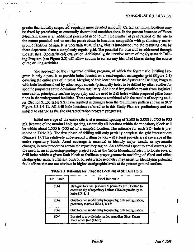
Table 2.3 Rationale for Proposed Locations of SD Drill Holes
Drill Hole Brief Rationale
SD-1 Half-grid location,just outside perimeter drift; located toconstrain dip of repository horizon (TSw2); proximity toholes UZ-4, -5
SD-2 Grid location modified by topography. drift configuration ,proximity to holes UZ-14. WT-9
SD-3 Grid location modified by topography, drift configuration
SD-4 Located to provide information regarding Ghost DanceFault offset (see SD-10)
Page 16 June4, 1993
YMP-SNL-SP 8.3.1.4.3.1, R1
Table 2.3 Rationale for Proposed Locations of SD Drill Holes
Drill Hole Brief Rationale
SD-5 Half-grid location modified by topography, drift configura-tion
SD-6 Grid location modified by topography, drift configuration.proximity to holes WT8. H-7
SD-7 Grid location modified by topography. drift configurationproximity to holes UZ-2. -3. -7
SD-8 Grid location modified by topography, drift configuration
SD-9 Grid location modified by topography, drift configuration.other drill holes
SD-10 Grid location modified by topography, drift configuration,also located to provide information along main drift align-ment and Ghost Dance Fault offset (see SD-4)
SD-11 Half-grid location modified by topography, drift configura-tion; also located to constrain transition from south ramp tomain drift alignments
SD-12 Half-grid location modified by topography, drift configura-tion; located to provide infomation along main drift align-ment
The known emplacement mechanisms of the Yucca Mountain tuff sequences suggest thatanisotropy may well exist. If so, the major axes of the anisotropy ellipse most likely will berelated to the location of the source caldera and transport direction of the erupted ash flows. ThePaintbrush tuffs at the site were derived from the Claim Canyon caldera segment and/or the Tim-ber Mountain/Oasis Valley caldera complex, located almost directly north of the repository block(Carr, 1988). The semi-regular, rectangular grid with axes oriented north-south and east-west pro-posed for the integrated drilling program is a compromise between the need for areal coverageand the anticipated orientation of anisotropy (Figure 2.1). The rectangular nature of the grid isamenable to modification and infill drilling, if necessary, to describe lateral anisotropy. The likeli-hood of anisotropy at Yucca Mountain related to transport direction of the major tuff units arguesagainst the use of a triangular grid.
Additional holes in the integrated drilling program (Table 2.1; Figure 1.3) are planned atspacings closer than approximately 3,000 ft (900 m) in order to provide geostatistical detail atshort separations. Some of these holes are spaced as closely as 100 ft (30 m) apart Because of theexpense and time involved in drilling, all holes of the Systematic Drilling Program are integratedwith drill holes planned by other site characterization studies (Table 2.1) in an effort to provideadequate geostatistical detail without creating unneeded penetrations of the site. Holes from otherdrilling programs are particularly important with regard to the close-spaced holes. For example,the UZ-9 complex (Study 8.3.1.2.2.3, Unsaturated Zone Percolation) requires very closely spacedholes for cross-hole pneumatic (gas-tracer) testing. By locating a few SD- holes nearby, the quan-tity of data representing short separation distances can be expanded greatly. Data from these
Page 17 June 4,1993
YMP-SNL-SP 8.3.1.4.3.1, R1
closely spaced holes plus information from the underground workings of the Exploratory StudiesFacility should allow adequate determination of the short-range spatial structure of the rock massforming the repository block. Understanding the short-range spatial continuity of barriers or con-duits for ground water flow may be of particular importance to assessing the performance of theYucca Mountain site.
Originally, the 2,500-3,000 ft hole spacing was intended to be within the range of correla-tion, based upon porosity data available from the tuffs of Calico Hills (see Table 2.2; Rautman,1991, which reports data originally collected in early 1987). However, more recently, additionalsampling (Rautman and others, 1991; Rautman and Flint, 1992) now suggests that the generalrange of correlation for matrix rock properties such as porosity may be an order of magnitude lessthan originally expected. Rautman and Flint suggest that the larger horizontal correlation dis-tances reported for the tuffs of Calico Hills may reflect the more geographically widespreadhomogeneous environment beneath a stagnant water table that formed the zeolitic alteration char-acteristic of the sampled rocks. The "typical" volcanic environment sampled more recentlyappears to be more variable. Additionally, the correlation distance for rock properties such as per-meability, may be less than that for porosity (Rautman, 1991). Because it seems unlikely that sur-face-based drilling can be conducted on the scale necessary to completely define spatialcontinuity patterns, additional sampling activities will be conducted on close spacings within thelong lateral drifts of the Exploratory Studies Facility (see section 2.2.4).
2.2.3 Location and Number of Down-Hole Samples
The number of samples to be taken down any particular drill hole will necessarily be acomposite determination developed by the interaction of the various studies that require samplesfrom the core to be acquired by this study (Table 1.1). Samples are actually allocated to eachrequesting study by the Sample Overview Committee via the process schematically outlined inSection 2.5.3. Any discussion in this Study Plan must be viewed in light of these ongoing anddrill-hole specific negotiations among interested Project participants.
Some general remarks are possible regarding plans for initial down-hole sampling for thespecific laboratory rock properties to be measured by this study. Rautman and Flint (1992) haveshown that vertical sample spacings on outcrop of approximately one sample every 5 ft (1.5 m) isadequate to reveal a large amount of detail regarding the distribution of the physical propertiesunder consideration. Accordingly, initial sampling for the laboratory testing described in Section3.4 of this Study Plan will be proposed at this frequency. For a "nominal" drill hole depth of 2,000ft (600 m), this sample spacing implies approximately 400 samples per drill hole. The exact num-ber of samples will vary as the proposed drill holes range in depth from 1,700 to 3,000 ft (500 to900 m). In keeping with the systematic philosophy of this study, samples will be proposed at reg-ular intervals in an effort to avoid introducing systematic bias into the properties thus measured.Obviously, it is impossible to avoid bias completely in dealing with real-world conditions, such ascompletely unconsolidated materials that physically cannot be sampled. However, systematicsampling will help avoid overt bias, and various approaches exist that will help evaluate the exist-ence of bias. For example, geophysical logs (Section 3.3) may suggest that the density of rock inan unsampled, poor recovery interval is less than for adjacent sampled intervals, thus at leastalerting the analyst to the potential for bias.
Page 19 June 4, 1993
YMP-SNL-SP 8.3.1.4.3.1, R1
Figure 2.1 Sketch map of the repository block showing proposed hole locations for the inte-grated drilling program and the underlying, conceptual, systematic grid the programis attempting to implement. Six-digit numbered tick-marks are Nevada State PlaneCoordinate System in feet.
Page 18 June 4,1993
YMP-SNL-SP 8.3.1.4.3.1, R1
The data of Rautinan and Flint (1992) also indicate that there are intervals wherein proper-ties are changing sufficiently rapidly (their Figure 3), that more closely spaced sampling may beindicated. Also, the correlation distances reported by these authors for other intervals are largeenough that the sampling requirements outlined above may be excessive, and fewer samples maybe required for adequate characterization. Because the exact applicability of outcrop samplinginformation to subsurface materials is not known, this study will evaluate information from thefirst one or two deep drill holes and modify the proposed sampling scheme accordingly. Evalua-tion methods are discussed in Section 3.5. The feedback mechanism for changing the samplingpattern is discussed in Sections 2.5 and 3.0.
2.2.4 Location and Number of Samples from the Exploratory Studies Facility
Plans for the location and number of samples from the Exploratory Studies Facility aresomewhat less well developed than for the surface drilling portion of this study. This condition isan artifact of the more limited and more constrained access for collecting the samples (there areonly two main test levels proposed in the Exploratory Studies Facility), and of the fact that theESF sampling is intended to supplement the development of spatial continuity patterns using drillhole data (where there are no such stratigraphic limitations).
The ultimate extent of underground sampling in the ESF workings (and associated testingactivities, see Section 3.4) will be determined by the evaluation of data, both from scoping studiesand more importantly from the surface drill holes (see Section 3.5.3). Locations of samples obvi-ously will be constrained to the final workings of the Exploratory Studies Facility. However, anappropriate subset of workings with differing orientations will be selected for systematic sam-pling once ESP construction is underway. Samples will be collected from the ribs using a portablecore drill or by collecting a large hand specimen and subcoring an appropriate sample for testingin the laboratory.
Preliminary indications of (stratigraphically) horizontal spatial correlation distances in thewelded and nonwelded (but not zeolitized) tuffs at Yucca Mountain (Table 2.2) suggest that sam-ple intervals on the order of 10 to 50 ft (3 to 15 m) may be required to resolve the close-orderaspects of horizontal spatial patterns with a total range of 350-500 ft (100-150 m). These horizon-tal sample spacings are obviously not possible with surface-based sampling. Samples will be col-lected at regular intervals, with allowance for locations rendered inaccessible by installation ofmine support equipment or facilities. If only the main northeast-southwest drifts and one completecrosscut of the repository area are considered, a minimum of 18,000 ft (5,500 m) of drift would beavailable for sampling on each of two test levels. At 50-ft (15 m) increments, 360 samples couldbe collected from the Topopah Spring repository level and an additional 360 samples from theCalico Hills test level. At 10-ft (3 m) spacing, the number of samples swells to 1,800 on eachlevel. This level of detail should provide for excellent resolution of spatial continuity patterns inthese two units. In practice, samples clustered at shorter spacings in several distributed areas prob-ably will be collected in preference to two long one-dimensional profiles along the main drifts.This practice would reduce the total number of samples to a more manageable number, while pro-viding the same spatial resolution (closest sample spacing).
Page 20 June 4, 1993
YMP-SNL-SP 8.3.1.4.3.1, R1
2.3 Study Plan Alternatives
There are no alternatives to obtaining information from the site itself for site characteriza-tion. The Systematic Drilling Program Activity of this study is essentially the only SCP study thatwill provide significant quantities of information from deep within the repository block, otherthan studies conducted within the Exploratory Studies Facility. The UZ- prefix drill holes (Unsat-urated Zone Percolation, Study 8.3.1.2.2.3) do provide similar information, generally in theimmediate vicinity of the block. However, these UZ- holes are more properly regarded as part ofthe "feature-of-interest" aspect of site characterization, and those holes that are located within theoutline of the proposed underground facilities (Figures 1.1, 1.3) may not be properly located toprovide systematic, and unbiased, areally representative information in the repository block. Bothsets of drill holes are intended to be considered collectively as part of the integrated site drillingeffort.
Core and other drill-hole data from a variety of locations within the outline of the reposi-tory block are required to develop the more objective geologic framework: stratigraphic contacts,location of the repository horizon and faults, measurement of engineering stability of the rockmass, and so on. Physical rock samples are required for descriptions and laboratory testing todetermine rock properties. Numerous studies have requested samples from the Systematic Drill-ing Program (Table 1.1). Although the general types of geologic features present, and the rangeand expected values of the various rock properties may be inferred from past experience in theYucca Mountain region, it is impossible to make location-specific predictions without examiningthe site itself. Interpretation of indirect geologic methods such as surface geophysics, regionalstratigraphy, or surface mapping yields results with sufficiently large uncertainties that they areinadequate for engineering design.
2.4 Study Plan Constraints
2.4.1 Potential Impacts on the Site
A first phase of twelve holes will be drilled as part of this study to various depths throughthe unsaturated zone; these holes will terminate below the static water table. Additional holes maybe drilled as part of this study if geostatistical evaluation of the data obtained from the initialtwelve holes indicates that more information is required for adequate site characterization.
Surface facilities associated with the drill holes include the drilling and ancillary equip-ment, power substations, and various trailers and temporary laboratory quarters. Actual surfacedisturbances include the drill pads and access roads. The drill holes themselves are the only sub-surface disturbance. Holes will be drilled dry to avoid introducing large quantities of water andsimilar fluids into the subsurface. Other than geophysical logging of the completed drill holes,there are no known in-situ activities planned for the SD- series holes that would affect subsurfaceconditions. Because such in-situ testing or monitoring activities would be conducted by a studyother than the Systematic Drilling Program, details of any testing or monitoring effects would bedescribed in the appropriate study plan(s).
On a broader scale, the Systematic Drilling Program is only one of a number of drilling
Page 21 June 4,1993
YMP-SNL-SP 8.3.1.4.3.1. R1
programs planned by the Yucca Mountain Site Characterization Project. Integration of drillingefforts, including evaluation of the effects of drilling on the site, is being conducted at the Projectlevel. Section 8.4 of the SCP discusses potential impacts of site activities on the waste isolationcharacteristics of the site and presents analyses to demonstrate that such studies do not impact thesite adversely. In particular, Section 8.4.3.2.5.2 discusses the effects of drilling on the site. Section8.43.2.5.1 discusses the effects of surface construction activities, including those related to drill-ing.
2.4.2 Logistical Limitations
The Systematic Drilling Program is constrained principally by the logistics of drilling.Drilling at the Nevada Test Site is expensive, and completion of individual drill holes requires asubstantial length of time (anticipated to be several months; see Sections 2.4.4 and 5.1.1). Further-more, not all geographic locations on Yucca Mountain are amenable to selection as a drill site.Surface topography (Figure 1.3) constrains the actual location, and in some cases, the generalspacing of drill holes as well.
Access and location constraints for the initial holes described in this Study Plan are notsevere. In general, drill holes are located on ridge crests or near the bottoms of washes. Steep side-hill locations are avoided. Although the holes proposed in the report are located to avoid accessacross steep slopes, the sparseness of the drilling pattern allows an acceptable variety of alternatelocations that meet the spacing requirements. Closely spaced holes are located in regions wheresurface topography is not a problem.
A somewhat more restrictive logistical constraint on the location of holes for the System-atic Drilling Program is the requirement contained in 10 CFR 60.10(d)(3) that such boreholes belocated "to the extent practical" in unexcavated pillar areas of the underground facility. This hasbeen accomplished by proposing that most SD- holes be drilled within pillars as shown on designdrawings being developed for advanced conceptual design (Figure 1.3). In practice, final engi-neering design of the repository will be worked around the actual "as-built" subsurface locationsof the drill holes, based upon down-hole deviation surveys (see Section 33).
Another logistical limitation that may affect the results of this study is the general inabilityof the drilling equipment anticipated for use by the Project (see also Section 3.1) to drill coreholes at an angle other than vertical. Many of the structural features (fault, joints) to be describedby this study are expected to occur at near-vertical angles. Such high-angle features are best inter-sected by surface-based drilling that is angled across the anticipated dip direction. On a Projectbasis, however (as opposed to for this study only), this logistical restriction is, not expected tolimit the quality of the data unduly. Other studies will conduct extensive mapping of structuralfeatures in the near-horizontal drifts of the Exploratory Studies Facility (Study 83.1.4.4.2, Char-acterization of Structural Features within the Site Area, Activity 8.3.1.4.2.2.4). The ESF driftswill be oriented almost ideally to describe high-angle structural discontinuities, particularly thosethat affect the actual repository horizon. Additionally, Study 8.3.1.4.22.4 (Characterization ofYucca Mountain Percolation in the Unsaturated Zone - ESF Study) contains an activity (Activity8.3.1.2.2.4.4, Radial Borehole Tests) that will drill several near-horizontal drill holes from theunderground ESF workings. These boreholes will also provide significant information on high-
Page 22 June 4, 1993
YMP-SNL-SP 8.3.1.4.3.1, R1
angle structural features within the immediate repository units.
2.4.3 Analytical Limitations
Most of the principal properties to be obtained directly by the Systematic Drilling programare descriptive and generally qualitative in nature, and they are acquired by geologic logging ofthe drill core. As such, the concept of "analytical limitations" is not particularly relevant, althoughthere are a number of procedural limitations that relate to operation of the Project Sample Man-agement Facility. For instance, geologists logging core in the custody of the Sample ManagementFacility are prohibited from performing standard logging activities such as scratching a mineral todetermine its hardness or applying a drop of hydrochloric acid to identify calcite from dolomite orfluorite. Conducting such trivial and accepted geologic "tests' would require a formal specimenrequest, action by the Sample Overview Committee, and permanent removal of the designatedcore specimen from the core box with the result that no other investigator would ever see thatpiece of core without special arrangements. Although there may be valid arguments in favor ofsuch restrictions, the effect of those procedural restrictions is to limit the ability of the geologist toperform his work in an timely and effective manner.
In any event, descriptions of the core are dependent upon the skill and experience of thegeologist performing the examination. Stratigraphic unit identifications inevitably are geologic-interpretations, and many of the contacts described at Yucca Mountain are gradational. Units maybe encountered in the subsurface that are not exposed at the surface, and the investigator may beunfamiliar with these rock types. A significant body of knowledge regarding the stratigraphy ofthe Yucca Mountain site does exist, and the personnel involved in this study are anticipated to beexperienced geologists. Accordingly, the descriptive information to be obtained by this study isexpected to meet accepted geologic standards (see also Section 3.7).
Some general observations are relevant with respect to the analytical limitations involvedin measuring the more quantitative material properties that will be determined on core samples.The integrated drilling program, of which the Systematic Drilling Program is only a part, isintended to describe a natural rock mass. Rock is, by its very nature, spatially variable. Mechani-cal limitations of the testing equipment to be used require relatively small physical specimens;many tests will use specimens of a few cubic centimeters to a few hundreds of cubic centimetersat most. Testing of such small samples will tend to increase the observed variability of any partic-ular rock property. The precision of most laboratory tests proposed undoubtedly far exceeds theaccuracy of those measurements in representing the effective property of any geologically signifi-cant volume of rock. Techniques exist to identify and quantify this small-scale variability; someof these methods are discussed in Section 3.5 of this Study Plan. Nevertheless, the natural com-plexity and multi-scale heterogeneity of a geologic environment must be considered when evalu-ating the analytical limitations of laboratory methods. Adequate sampling at small spatialseparations is essential for adequate quantification of such small-scale variability.
The issue of adequate sampling at small spatial separations probably applies only to hori-zontal sampling as related to the spacing of individual drill holes. Down-hole samples can beobtained practically as close together as desired within reason. Limitations on total numbers ofdrill holes and horizontal drill hole spacings point out the necessity of horizontal sampling within
Page 23 June 4,1993
YMP-SNL-SP 8.3.1.4.3.1, R1
the lateral drifts of the Exploratory Studies Facility.
The laboratory determinations of rock properties that will be conducted directly under thisstudy (see Section 3.4) all involve standard tests. Analytical methods to support these determina-tions are considered adequate, and no extraordinary considerations are involved. The accuracyand precision of specific proposed tests are discussed in Section 3.7, and the test methodologiesare described in Sections 3.4.1 and 3.4.2.The caveat regarding block-scale properties discussed inthe immediately preceding paragraph applies to these rock property determinations. Discussion ofthe analytical limitations involved in measurement of specific rock properties to be measured byother SCP studies on samples obtained by this study can be found in the study plans for the stud-ies actually conducting those measurements.
24.4 Time Constraints
A tentative, schematic schedule of work activities and reports is presented in Section 5 ofthis Study Plan. The schedule indicates that the 12 drill holes proposed for this study (plus holesdrilled for other SCP programs that will provide additional geostatistical information) could becompleted some 60 months after the initiation of drilling. This schedule, although preliminary andsomewhat conceptual, will provide adequate time to complete the geostatistical evaluation androck properties modeling of data from the Systematic Drilling Program for use in the license.application. Information from the earlier-drilled holes will be available for use in advanced con-ceptual design. Because each drill hole will be reported independently following completion,design and performance activities may be based upon the data extant as of any arbitrary cutoffdate. Obviously, design specifications predicated upon an unreasonably limited suite of data mayneed to be revised as more data are acquired. It should be noted that the drilling schedule is partic-ularly critical because of the large number of studies that depend upon samples from the drillingeffort (Table 1.1). Delay of the Systematic Drilling Program will delay rock-property testing pro-grams, which in turn, will delay performance assessment and design analyses that require rock-properties data.
The current Project drilling schedule using multiple dual-wall, reverse-circulation corerigs and an average, best-guess estimate of the time required to drill each hole provides adequatetime for the completion of this study prior to the license application. However, should the geo-statistical evaluation indicate that current estimates of horizontal spatial correlation are too highand that closer drill hole spacing is required for adequate characterization, the time available foran expanded program of in-fill drilling may be inadequate. Also, the Systematic Drilling Program(or other repository-focused drilling programs) may identify geologic features or conditions (pos-sible examples: faults, perched water zones, etc.) that require specific, more detailed characteriza-tion, again requiring additional drill holes and tests. Should these circumstances occur,alternatives will be evaluated. Improved estimates of the schedule will become available oncedrilling starts, and experience is gained regarding actual penetration rates for the available drillingequipment and the actual lithologies encountered at Yucca Mountain. Conduct of the Projectdrilling effort should be viewed as an iterative activity, as described below in Sections 2.23,2.5.1, 2.5.2, and 2.5.3 (see also Figure 2.2). Evaluation of the adequacy of the planned programwill be conducted on an on-going basis (Section 3.5).
Page 24 June 4,1993
YMP-SNL-SP 8.3.1.4.3.1, R1
2.5 Interrelationships of this Study to Other SCP Studies
As introduced in Section 1.1 (above), this study is unique in its focus on a restricted geo-graphic area, rather than on some particular physical process or phenomenon. Site characteriza-tion at Yucca Mountain is directed toward the understanding how certain physical processes affecta limited parcel of real estate: the proposed repository block and the controlled area to the limitsof the accessible environment (Figure 1.1). Understanding these processes is critical to evaluatingthe potential performance of the site with respect to waste isolation. Some processes operate on ascale larger than the repository block, for example, regional ground water flow, and thus mayrequire evaluation over that complete scale. Description of other processes may require special-ized measurements or sophisticated equipment. Measurement of fracture mechanical propertiessuch as resistance to shear movement might be an example. Still other processes may require"active" testing that may more safely be conducted outside the immediate repository region;large-scale hydrologic pump tests or injection tests to determine aquifer characteristics mightillustrate this category. The unifying principle behind all of the various process-oriented studies isthe application of the understanding developed to the potential repository site itself. Absent this,the Yucca Mountain Project is merely conducting interesting science, not site characterization.
The interrelationship of this study to other SCP studies, shown schematically in the logicdiagram of Figure 2.2, is perhaps best understood by examining the next higher level setting inwhich this particular study has been placed. This Study 8.3.1.4.3.1 is part of SCP Investigation8.3.1.4.3, which is entitled "Development of Three-Dimensional Models of Rock Characteristicsat the Repository Site." The other study under this Investigation is purely a modeling activity; alldata for Study 8.3.1.4.3.2, Three-Dimensional Rock Characteristics Models, is assumed to comefrom elsewhere in the site characterization program. The completed "three-dimensional models ofrock characteristics at the repository site" are then used as input to performance assessment ordesign calculations of various types. Why, then, is a site-based characterization effort (a drillingprogram) intimately associated with an investigation described as development of ... models? Theanswer to the question is that understanding the physics of ground water movement or of rockdeformation in general may be insufficient to provide the site-specific description required forprediction of future events and assessing the performance of a nuclear waste repository to belocated at such-and-such geographic coordinates. The Systematic Acquisition of Site-SpecificSubsurface Information Study is intended to provide this particular type of information complete-ness, while at the same time relying on other, more process-oriented studies to provide the contextfor that information.
Just as it is obvious that this study cannot, by itself, provide all the site informationrequired for a license application, it is also clear that integration of the myriad of site characteriza-tion studies being conducted by the Department of Energy cannot be accomplished through thisStudy Plan. Many issues of integration among studies alluded to in this document must beaddressed on an ongoing and evolving basis by other Project management structures.
2.5.1 Information Flow and Evaluation of Data Completeness
In conducting a characterization effort sufficient to develop a license application, the flowof information and/or materials cannot be a one-way street. Because the purpose of site data col-
Page 25 June 4,1993
YM-SNL-SP 8.3.1.4.3.1, R1
lection is to support design and performance modeling, some mechanism must exist to ensure thatthe aggregate of site data is sufficient for the task at hand. Preferably, this feedback mechanismoperates in "real time," providing the opportunity to adjust site characterization efforts to accom-modate new data and an evolving understanding of the site.
Because of its areal focus on "the site" and its close relationship to the modeling activitiesof the broader investigation, this study is uniquely situated to provide this sort of feedback mech-anism. Although the ultimate evaluation of data completeness belongs to performance assessmentand/or design activities discussed elsewhere in the SCP, a good preliminary assessment of dataadequacy and the identification of gross discrepancies between existing collection strategies andthe implications of the data themselves can be conducted as part of the statistical and geostatisti-cal evaluation of data described in Section 3.5 of this Study Plan (below).
2.5.2 Physical Properties Sampling and Testing
Sections 1.2 and 1.3 (among others in this Study Plan) state that the Systematic DrillingProgram Activity will provide physical sample materials for laboratory testing. Because of thebroad scope of "laboratory testing" and the specialized nature of many of the tests required, it ismost appropriate to delegate measurement of most of these laboratory properties to the appropri-ate process-oriented site characterization study. Thus, the majority of the studies listed in able1.1 and shown on the logic diagram of Figure 2.2 will request, receive, and test rock samples fromthe Systematic Drilling Program under the provisions of their own Study Plans and supportingdocuments. An understanding and acceptance of this philosophy is assumed throughout this studyPlan. The return flow of feedback is also assumed and is shown in Figure 2.2 through the arrowlabeled 'Evaluation and Feedback." Discussion of the mechanical details of the required integra-tion is provided in Section 2.53 immediately below.
In addition to the delegation of general laboratory testing to a number of process-orientedstudies (Table 1.1), the investigation-level purpose of this study (i.e. the construction of three-dimensional rock characteristics models) requires that a certain amount of physical properties(rock characteristics) testing be conducted under the direct control of this study in order to ensuretimeliness of testing, completeness of sampling and rapid feedback of the required information.This suite of rock properties is restricted to measurements that are believed to reflect quantita-tively the geologic framework of the mountain (drawing on work of Rautman and Flint, 1992) andthat are obtainable without particularly sophisticated equipment or testing techniques. The spe-cific rock properties measurements conducted as part of this Study Plan are listed briefly in Sec-tion 1.2 and are described in detail in Section 3.4. To ensure compatibility of testing results, thisstudy will make use of the same techniques and procedures developed by the process-orentedstudy with primary responsibility for the relevant rock properties.
2.53 Mechanism of Integration
Maintaining integration of an effort as broad in scope as that represented conceptually inFigure 2.2 will not be easy. Other than informal agreements to cooperate between individual prin-cipal investigators, coordination of effort must be accomplished at the Project level in that thestudies involved are conducted by investigators from different Project participants. Definition of
Page 26 June 4 1993
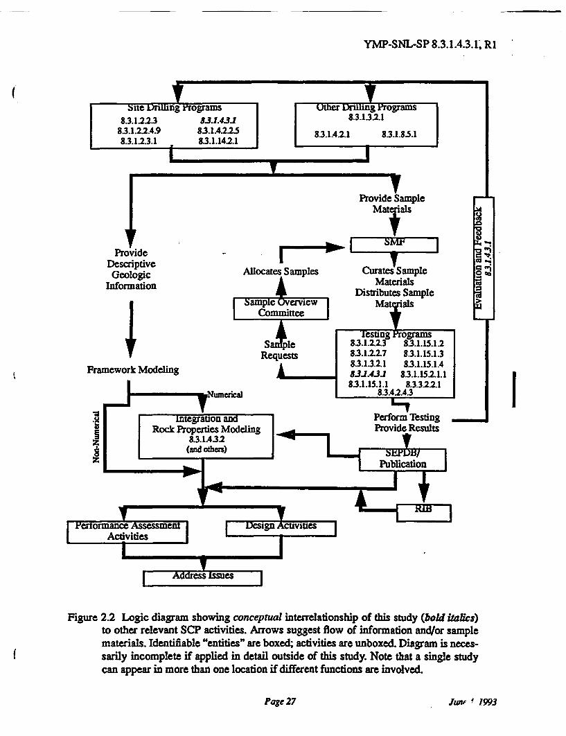
YMP-SNL-SP 8.3.1.4.3.1. R1
Figure 2.2 Logic diagram showing conceptual interrelationship of this study (bold italics)to other relevant SCP activities. Arrows suggest flow of information and/or samplematerials. Identifiable "entities" are boxed; activities are unboxed. Diagram is neces-sarily incomplete if applied in detail outside of this study. Note that a single studycan appear in more than one location if different functions are involved.
Page 27 June 1, 1993
YMP-SNL-SP 8.3.1.4.3.1, R1
such more formal coordination efforts are beyond the scope of this or of any other particularstudy. Nevertheless, some general discussion is possible in this Study Plan.
As indicated in Figure 2.2, the Project-level Sample Overview Committee plays an auxil-iary, "counter-current" role in the generally unidirectional flow of information and sample mater-als. No drilling program (shown at the top of the logic diagram) fully "owns" or controls the coreand other samples that it produces. Samples are a Project resource, and the means of allocation isthrough the Sample Overview Committee. Although the study conducting a particular drillingeffort presumably has some priority when requesting sample materials, that priority is not abso-lute. Sample requests are processed by the Sample Overview Committee on a hole-by-hole basis,with certain sampling activities determined a priori in advance of drilling when required to pre-serve in situ conditions that would otherwise deteriorate. Other requests follow examination of therecovered core by a particular principal investigator. Given the sample-allocation authority of thecommittee (which is actually only a recommendation to the Project Manager), it would appearthat the Sample Overview Committee serves as a principal mechanism for the integration of sam-pling, testing, and data-adequacy evaluation necessary for success of site characterization. Provi-sions for the return of testing results and the joint evaluation of sampling adequacy must beincluded in the allocation authority.
Coordination of the physical drilling and other drillsite activities will be accomplishedthrough the test-planning packages and job packages, the inter-participant "contracts" that com-prise the actual instructions to the Project architect/engineer, drillers, and other support organiza-tions, such as the sample management facility (see also Sections 3.1 and 3.2). Because the test-planning package and job package are ad hoc documents developed essentially on a hole-by-holebasis with input from all interested Project participants, it is impossible for the Study to specifycompletely and in advance the requirements for Systematic Drilling Program drill holes.
Another mechanism for integrating separate activities across Project participants is theformal interface control process specified by the Project quality assurance program.
Page 28 June 4, 1993
YMP-SNL-SP 8.3.1.4.3.1, R1
3.0 DESCRIPTION OF STUDY PLAN ACTIVITY
The Systematic Drilling Program described in the Site Characterization Plan consists ofone activity. Although there is only one activity, description of the study is facilitated by consider-ing a number of relatively distinct, separate tasks. Figure 3.1 portrays the general sequence oftasks related to the Systematic Drilling Program: (1) drill, (2) create geologic log, (3) conductgeophysical logging, (4) measure rock properties, and (5) evaluate data. Of these separate tasks,only the geologic logging (item 2), a small portion of the laboratory testing for rock properties(item 3), and evaluation of the data for drilling impacts (item 5) are actually conducted by investi-gators working under this study. Because the Systematic Drilling Program Activity is tied to thelogistics of drilling, the next hole will be started soon after completion of the previous hole.Accordingly, more than one five-step sequence may be underway at any particular time. Thesefive tasks are discussed at greater length below.
In general, work under this Study Plan will be conducted under the scientific notebooksystem. Certain activities may be codified in technical procedures. All technical procedures forthis study that are internal to Sandia are listed in Table 3.1. Procedures for general (i.e., those notconducted under this study) laboratory rock-properties testing of samples from the SystematicDrilling Program are the responsibility of the studies conducting that testing. As discussed belowin Section 3.4, technical procedures for rock properties testing conducted directly by this studywill be adopted from the process-oriented study(ies) having "primary" responsibility for the test-ing in question.
Table 3.1 Technical Procedures for This Study
Procedure ID Title Date
EP-0036 Field Research Program for Unsaturated Flow and 9/28/90Transport Experiments
TP-0162 Geologic Description and Core Logging TBD
TP-0217 Laboratary Determination of Rock Properties TBD
3.1 Task 1,Drilling
Drilling of holes for the Systematic Drilling Program will provide the physical rock sam-ples that are essential to both this study and to many other parts of the Yucca Mountain Project.This and all other site drilling will be conducted under policies and guidelines established by theYucca Mountain Project. Discussion of factors determining such policies are found in Section 8.4of the SCP.
The initial proposed holes for the Systematic Drilling Program are shown in Figure 1.3.The locations of these holes reflect consideration of logistical factors such as road access, topo-graphic slope and pad area, preliminary estimates of spatial variability, expected locations of pil-lars in the underground facilities, and relationship to other proposed drill holes. Actual locationsand other specifications will be finalized in formal job packages prior to the start of drilling.
Page 29 June 1 1993
YMP-SNL-SP 8.3.1.4.3.1, R1
Drilling operations will be conducted by a Nevada Test Site support contractor, ReynoldsElectrical and Engineering Company (REECo). Specific operating procedures for drilling are theresponsibility of REECo. Engineering specifications for drilling are developed by the ProjectArchitect/Engineer, Raytheon Services Nevada in consultation with all interested Project partici-pants (which includes this study). Because of the complex interplay - and potential conflicts -between requirements of the various studies that will use core from the Systematic Drilling Pro-gram or that will utilize the completed holes as in situ test facilities, the actual specifications foreach hole will be finalized in formal job packages on a hole-by-hole basis developed by consulta-tion among interested parties prior to the start of drilling (Section 2.5). Also, experience gainedthrough early drilling at the site in all likelihood will result in modifications to the currently antic-ipated drilling criteria.
Preliminary requirements have been established and several prototype holes have beenconstructed off-site. Briefly, drilling will be done dry, without the introduction of water-based flu-ids into the hole in order to minimize alteration of in situ conditions or the hydrologic propertiesof the recovered core samples. Drilling will use a modified dual-wall reverse-circulation tech-nique to obtain (nominally) continuous core. The minimum acceptable (usable) core size is NC orHQ wireline core: approximately two-and-a-half inches (6 cm) in diameter. Holes will be loggedat appropriate points during and after the drilling process using various geophysical instrumentsas discussed in Section 3.3. The hole will be surveyed after completion to provide documentationof deviation from initial orientation.
3.2 Task 2, Geologic Logging and Description of Core
"Logging" of drill core with respect to the Yucca Mountain Project is a somewhatinvolved process that comprises the technical work of many studies and Project participants.Although the entire scope of "logging" is beyond this Study Plan, some conceptual remarksappear appropriate due to the multipurpose, integrative nature of this particular Study (Section2.5). "Logging" begins at the rig site with preparation of a preliminary description of rock typesand major geologic features, core recoveries, drill-bit usage, and penetration rates by the ProjectSample Management Facility drilling support staff. This log contains administrative-type infor-mation necessary for daily management reporting and making real-time drilling decisions. It alsoprovides the formal record for quality assurance purposes of what core actually was recoveredand from what intervals. Following transport of the core to the Sample Management Facility, thecore is available for examination and detailed "logging" by all Project participants. The scope ofthe logging activity will vary depending upon the purpose of the particular study involved. Forexample, core may be logged simply to identify the occurrence of calcite veining preparatory torequesting samples of calcite through the Sample Overview Committee for chemical analyses.Another "log" may be created to examine in detail fracture characteristics (roughness, aperture,infillings) relevant to rock-mass stability. These types of logs are the responsibility of thestudy(ies) intending to use core from the Systematic Drilling Program (e.g., Table 1.1).
1. Note that most rig-site operations are under the purview of the Project Sample Management Facility (seeSection 2.5. Table 3.7),which operates under its own set of procedural specifications. Various additionalrig-site activities by Sample Management Facility personnel may be required to support this and/or otherstudies. Such time-critical activities are the responsibility of the appropriate study and are specified in thehole-specific Job Pakage(s).
Page31 June4,1993
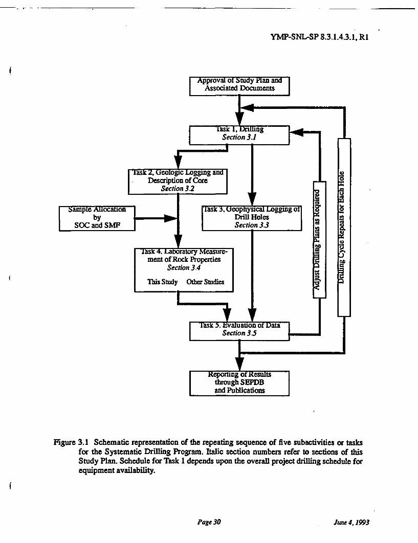
YMP-SNL-SP 8.3.1.4.3.1, R1
Figure 3.1 Schematic representation of the repeating sequence of five subactivities or tasksfor the Systematic Drilling Program. Italic section numbers refer to sections of thisStudy Plan. Schedule for Task 1 depends upon the overall project drilling schedule forequipment availability.
Page 30 June 4,1993
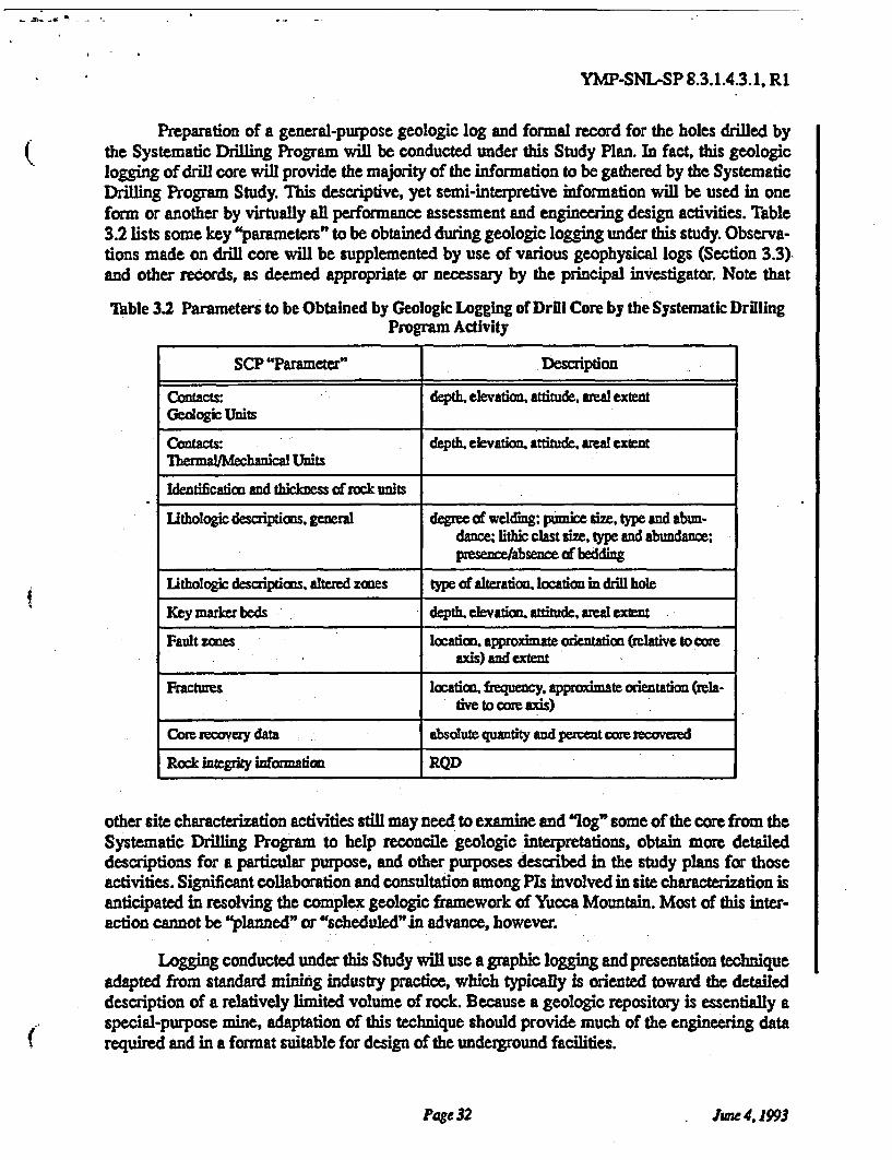
YMP-SNL-SP 8.3.14.3.1, R1
Preparation of a general-purpose geologic log and formal record for the holes drilled bythe Systematic Drilling Program will be conducted under this Study Plan. In fact, this geologiclogging of drill core will provide the majority of the information to be gathered by the SystematicDrilling Program Study. This descriptive, yet semi-interpretive information will be used in oneform or another by virtually all performance assessment and engineering design activities. Table3.2 lists some key "parameters" to be obtained during geologic logging under this study. Observa-tions made on drill core will be supplemented by use of various geophysical logs (Section 3.3)and other records, as deemed appropriate or necessary by the principal investigator. Note that
Table 3.2 Parameters to be Obtained by Geologic Logging of Drill Core by the Systematic DrillingProgram Activity
SCP "Parameter" Description
Contacts: depth. elevation, attitude, areal extentGeologic Units
Contacts: depth, elevation attiude. areal extentThermal-Mechanical Units
Identification and thickness of rock units
Lithologic descriptions, general degree of welding; pumice size, type and abun-dance; lithic clast size, type and abundance;presence/absence of bedding
Lithologic descriptions, altered zones type of alteration, location in drill hole
Key marker beds depth. elevation, attitude, areal extent
Fault zones location approximate orientation (relative to coreaxis) and extent
Fractures location, frequency, approximate orientation (rela-ive to core axis)
Core recovey data absolute quantity and percent core recovered
Rock integrity information RQD
other site characterization activities still may need to examine and "log" some of the core from theSystematic Drilling Program to help reconcile geologic interpretations, obtain more detaileddescriptions for a particular purpose, and other purposes described in the study plans for thoseactivities. Significant collaboration and consultation among PIs involved in site characterization isanticipated in resolving the complex geologic framework of Yucca Mountain. Most of this inter-action cannot be "planned" or "scheduled"in advance, however.
Logging conducted under this Study will use a graphic logging and presentation techniqueadapted from standard mining industry practice, which typically is oriented toward the detaileddescription of a relatively limited volume of rock. Because a geologic repository is essentially aspecial-purpose mine, adaptation of this technique should provide much of the engineering datarequired and in a format suitable for design of the underground facilities.
Page 32 June4, 1993
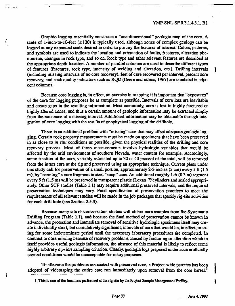
YMP-SNL-SP 8.3.1.4.3.1, R1
Graphic logging essentially constructs a "one-dimensional" geologic map of the core. Ascale of 1-inch-to-10-feet (1:120) is typically used, although zones of complex geology can belogged at any expanded scale desired in order to portray the features of interest Colors, patterns,and symbols are used to indicate the location and orientation of faults, fractures, alteration phe-nomena, changes in rock type, and so on. Rock type and other relevant features are described atthe appropriate depth location. A number of parallel columns are used to describe different typesof features (fractures, rock type, intensity of welding and alteration, etc.). Drilling intervals(including missing intervals of no core recovery), feet of core recovered per interval, percent corerecovery, and rock quality indicators such as RQD (Deere and others, 1967) are tabulated in adja-cent columns.
Because core logging is, in effect, an exercise in mapping it is important that "exposures"of the core for logging purposes be as complete as possible. Intervals of core loss are inevitableand create gaps in the resulting information. Most commonly, core is lost in highly fractured orhighly altered zones, and thus a certain amount of geologic information may be extracted simplyfrom the existence of a missing interval. Additional information may be obtainable through inte-gration of core logging with the results of geophysical logging of the drillhole.
There is an additional problem with "missing" core that may affect adequate geologic log-ging. Certain rock property measurements must be made on specimens that have been preservedin as close to in situ conditions as possible, given the physical realities of the drilling and corerecovery process. Most of these measurements involve hydrologic variables that would beaffected by the arid environment of southern Nevada, water content for example. Accordingly,some fraction of the core, variably estimated up to 30 or 40 percent of the total, will be removedfrom the intact core at the rig and preserved using an appropriate technique. Current plans underthis study call for preservation of a small portion, approximately 2-3 inches (5 cm) every 5 ft (1.5m), by "canning" a core fragment in steel "soup" cans. An additional roughly 1-ft (0.3 m) segmentevery 5 ft (1.5 m) will be preserved in transparent plastic (Lexan )cylinders and sealed appropri-ately. Other SCP studies (Table 1.1) may require additional preserved intervals, and the requiredpreservation techniques may vary. Final specification of preservation practices to meet therequirements of all relevant studies will be made in the job packages that specify rig-site activitiesfor each drill hole (see Section 25.3).
Because many site characterization studies will obtain core samples from the SystematicDrilling Program (Table 1.1), and because the final method of preservation cannot be known inadvance, the protection and immediate removal of sensitive hydrologic specimens itself may cre-ate individually short, but cumulatively significant, intervals of core that would be, in effect, miss-ing for some indeterminate period until the necessary laboratory procedures are completed. Incontrast to core missing because of recovery problems caused by fracturing or alteration which initself provides useful geologic information, the absence of this material is likely to reflect somehighly arbitrary a priori sampling criterion. Clearly, geologic logs prepared under such artificiallycreated conditions would be unacceptable for many purposes.
To alleviate the problems associated with preserved core, a Project-wide practice has beenadopted of videotaping the entire core run immediately upon removal from the core barreL
1. This is one of the functions performed at the rig site by the Project Sample Management Facility.
Page 33 June 4, 1993
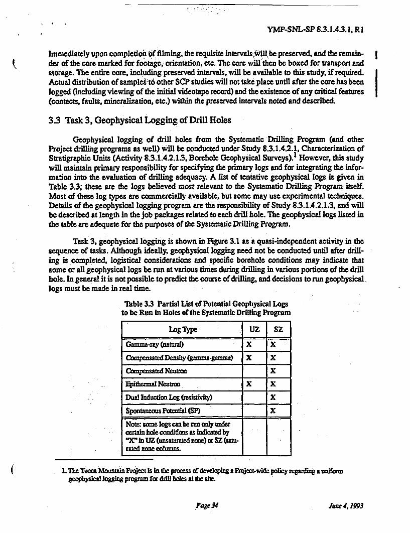
YMP-SNL-SP 8.3.1.4.3.1, R1
Immediately upon completion of filming, the requisite intervals will be preserved, and the remain-der of the core marked for footage, orientation, etc. The core will then be boxed for transport andstorage. The entire core, including preserved intervals, will be available to this study, if required.Actual distribution of samples to other SCP studies will not take place until after the core has beenlogged (including viewing of the initial videotape record) and the existence of any critical features(contacts, faults, mineralization, etc.) within the preserved intervals noted and described.
3.3 Task 3, Geophysical Logging of Drill Holes
Geophysical logging of drill holes from the Systematic Drilling Program (and otherProject drilling programs as well) will be conducted under Study 83.1.4.2.1, Characterization ofStratigraphic Units (Activity 8.3.1.4.2.1.3, Borehole Geophysical Surveys).' However, this studywill maintain primary responsibility for specifying the primary logs and for integrating the infor-mation into the evaluation of drilling adequacy. A list of tentative geophysical logs is given inTable 3.3; these are the logs believed most relevant to the Systematic Drilling Program itself.Most of these log types are commercially available, but some may use experimental techniques.Details of the geophysical logging program are the responsibility of Study 8.3.1.4.2.1.3, and willbe described at length in the job packages related to each drill hole. The geophysical logs listed inthe table are adequate for the purposes of the Systematic Drilling Program.
Task 3, geophysical logging is shown in Figure 3.1 as a quasi-independent activity in thesequence of tasks. Although ideally, geophysical logging need not be conducted until after drill-ing is completed, logistical considerations and specific borehole conditions may indicate thatsome or all geophysical logs be run at various times during drilling in various portions of the drillhole. In general it is not possible to predict the course of drilling, and decisions to run geophysical.logs must be made in real time.
Table 3.3 Partial List of Potential Geophysical Logsto be Run in Holes of the Systematic Drilling Program
Log Type UZ SZ
1. The Yucca Mountain Project is in the process of developing a Project-wide policy regarding a uniformgeophysical logging program for drill holes at the site.
Page34 June 4 1993
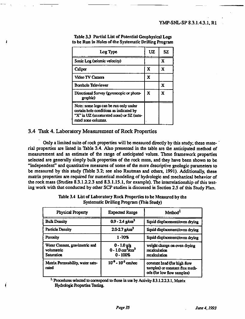
YMP-SNL-SP 8.3.1.4.3.1, R1
Table 3.3 Partial List of Potential Geophysical Logsto be Run in Holes or the Systematic Drilling Program
Log Type UZ SZ
Note: some logs can be rum only undercertain hole conditions as indicated by"X" in UZ (unsaturated zone) or SZ (satu-rated zone columns.
3.4 Task 4. Laboratory Measurement of Rock Properties
Only a limited suite of rock properties will be measured directly by this study; these mate-rial properties are listed in Table 3.4. Also presented in the table are the anticipated method ofmeasurement and an estimate of the range of anticipated values. These framework propertiesselected are generally simply bulk properties of the rock mass, and they have been shown to be"independent" and quantitative measures of some of the more descriptive geologic parameters tobe measured by this study (Table 3.2; see also Rautman and others, 1991). Additionally, thesematrix properties are required for numerical modeling of hydrologic and mechanical behavior ofthe rock mass (Studies 8.3.1.2.2.3 and 8.3.1.15.1. for example). The interrelationship of this test-ing work with that conducted by other SCP studies is discussed in Section 2.5 of this Study Plan.
Table 3.4 List or Laboratory Rock Properties to be Measured by theSystematic Drilling Program (This Study)
Physical Property Expected Range Method
Procedures selected to correspond to those in use by Activity 83.1.223.1, MatrixHydrologic Properties Testing.
Page 35 June 4, 1993
YMP-SNL-SP 8.3.1.4.3.1, R1
A compilation of all rock properties testing that is expected to be performed on core samplesobtained by the Systematic Drilling Program is provided in Table 3.5.
Table 35 Rock Properties to be Measured on Core from the Systematic DrillingProgram by All Project Participants (compiled from the SCP). Work by this Study
Shown in Bold Italics (compare to Table 3.4.
Brief Description Participant SCP Study
Page36 June 4,1993
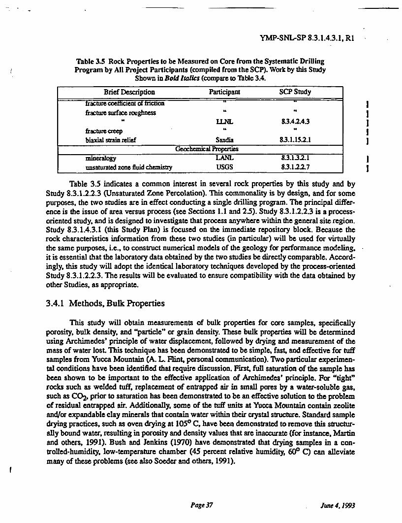
YMP-SNL-SP 8.3.1.4.3.1, R1
Table 3.5 Rock Properties to be Measured on Core from the Systematic DrillingProgram by All Project Participants (compiled from the SCP). Work by this Study
Shown in Bold Italics (compare to Table 3.4.
Brief Description Participant SCP Study
Table 3.5 indicates a common interest in several rock properties by this study and byStudy 8.3.1.2.2.3 (Unsaturated Zone Percolation). This commonality is by design, and for somepurposes, the two studies are in effect conducting a single drilling program. The principal differ-ence is the issue of area versus process (see Sections 1.1 and 2.5). Study 8.3.1.2.2.3 is a process-oriented study, and is designed to investigate that process anywhere within the general site region.Study 8.3.1.4.3.1 (this Study Plan) is focused on the immediate repository block. Because therock characteristics information from these two studies (in particular) will be used for virtuallythe same purposes, i.e., to construct numerical models of the geology for performance modeling,it is essential that the laboratory data obtained by the two studies be directly comparable. Accord-ingly, this study will adopt the identical laboratory techniques developed by the process-orientedStudy 8.3.1.2.2.3. The results will be evaluated to ensure compatibility with the data obtained byother Studies, as appropriate.
3.4.1 Methods, Bulk Properties
This study will obtain measurements of bulk properties for core samples, specificallyporosity, bulk density, and "particle" or grain density. These bulk properties will be determinedusing Archimedes' principle of water displacement, followed by drying and measurement of themass of water lost. This technique has been demonstrated to be simple, fast, and effective for tuffsamples from Yucca Mountain (A. L. Flint, personal communication). Two particular experimen-tal conditions have been identified that require discussion. First, full saturation of the sample hasbeen shown to be important to the effective application of Archimedes' principle. For "tight"rocks such as welded tuff, replacement of entrapped air in small pores by a water-soluble gas,such as CO2, prior to saturation has been demonstrated to be an effective solution to the problemof residual entrapped air. Additionally, some of the tuff units at Yucca Mountain contain zeoliteand/or expandable clay minerals that contain water within their crystal structure. Standard sampledrying practices, such as oven drying at 1050 C, have been demonstrated to remove this structur-ally bound water, resulting in porosity and density values that are inaccurate (for instance, Martinand others, 1991). Bush and Jenkins (1970) have demonstrated that drying samples in a con-trolled-humidity, low-temperature chamber (45 percent relative humidity, 600 C) can alleviatemany of these problems (see also Soeder and others, 1991).
Page 37 June 4,1993
YMP-SNL-SP 8.3.1.4.3.1, R1
3.4.2 Methods, Hydrologic Properties
This study will obtain measurements of several hydrologic properties, including the statevariables of water content and saturation. These properties do not fit the principal intent of labora-tory measurement of framework properties that assist in developing the three-dimensional rockcharacteristics model. In general, they are more properly part of a process-oriented study such asStudy 83.12.23. However, the information is important to the overall Project, is easy to mea-sure, and must be obtained (if it is going to be obtained) prior to any other testing. In addition tothe state variables, measurements of specific permeability to water (which is equivalent to hydrau-lic conductivity) will be obtained by this study. Saturated matrix permeability is a frameworkproperty of vital interest to the rock characteristics modeling effort.
Gravimetric water content will be measured from the initial and "dried" weights of a coresample that has been preserved at the drill site to prevent evaporation of in situ moisture. Volu-metric water content and saturation are recomputed from this basic data adjusting for bulk densityand porosity of the rock. Drying of the sample to prevent the undesired loss of structurally boundwater contained in zeolites and clay minerals is an issue similar to that discussed in Section 3.4.1(above), and will be dealt with in similar manner.
Matrix permeability will be measured assuming Darcy flow using standard API (Ameri-can Petroleum Institute) single-phase techniques in accordance with methods adopted by process-oriented Study 8.3.1.2.2.3 (Unsaturated Zone Percolation). A constant head approach has beenadopted for samples capable of sustaining relatively high flow rates, whereas a constant fluxapproach has been adopted for samples capable of sustaining lower rates of flow.
3.5 Task 5. Evaluation of Data
The objective of site characterization is to provide information for use in designing andassessing the performance of the potential repository at Yucca Mountain. It therefore follows thatthe final determination of information adequacy is the purview of these activities. Nevertheless,such a final determination is far removed from the field operations of this study both in time andin logic. More immediate indicators of likely data adequacy or obvious inadequacy are required toguide these activities.
A problem relevant to the conduct of the Systematic Drilling Program itself is the determi-nation of sample spacing, and thus the number of samples. The number and preliminary spacingof both drill holes and down-hole samples is discussed in Section 2.2. Although the preliminarydecisions documented in these sections are based on the best available knowledge from scopingactivities in the vicinity of the site, the information obtained from the subsurface of Yucca Moun-tain may be quite different. It is therefore essential that data obtained from the drill holes bereported and evaluated on an on-going basis. In this manner, it may be possible to adjust the sam-pling and laboratory rock-properties programs to produce more valuable information. This feed-back mechanism is illustrated in Figures 2.2 and 3.1
-There are essentially two approaches to the preliminary evaluation of data adequacy to beconducted by this study (i.e., an evaluation not based on the results of performance assessment
Page 38 June 4,1993
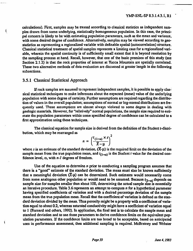
YMP-SNL-SP 8.3.1.4.3.1, R1
calculations). First, samples may be treated according to classical statistics as independent sam-ples drawn from some underlying, statistically homogeneous population. In this case, the princi-pal concern is likely to be with estimating population parameters, such as the mean and variance,with some desired degree of confidence. Alternatively, samples may be viewed according to geo-statistics as representing a regionalized variable with definable spatial (autocorrelation) structure.Classical statistical treatment of spatial samples represents a limiting case for a regionalized vari-able, wherein the spatial continuity is of sufficiently small extent that it is beyond resolution bythe sampling process at hand. Recall, however, that one of the basic premises of this study (seeSection 2.1.2) is that the rock properties of interest at Yucca Mountain are spatially correlated.These two alternative methods of data evaluation are discussed at greater length in the followingsubsections.
3.5.1 Classical Statistical Approach
If rock samples are assumed to represent independent samples, it is possible to apply clas-sical statistical techniques to make inferences about the expected (mean) value of the underlyingpopulation with some degree of certainty. Further assumptions are required regarding the distribu-tion of values in the overall population; assumptions of normal or log-normal distributions are fre-quently used. These assumptions are almost always violated to some degree in dealing withgeologic materials. However, for "relatively" normal populations, the sample size required to esti-mate the population parameters within some specified degree of confidence can be calculated to afirst approximation using these techniques.
The classical equation for sample size is derived from the definition of the Student t-distri-bution, which may be rearranged as
where s is an estimate of the standard deviation, (X-) is the required limit on the deviation of thesample mean from the true population mean, and is the Student t value for the desired con-fidence level, a, with n degrees of freedom.
Use of the equation to determine n prior to conducting a sampling program assumes thatthere is a "good" estimate of the standard deviation. The mean must also be known sufficientlythat a meaningful deviation can be determined. Such estimates would necessarily comefrom some analogous other population or would need to be assumed. Because depends onsample size for samples smaller than about 100, determining the actual sample size is essentiallyan iterative procedure. Table 3.6 represents an attempt to compute n for a hypothetical parameterhaving specified coefficients of variation and with a desired percentage deviation of the samplemean from the true population mean. Recall that the coefficient of variation is defined as the stan-dard deviation divided by the mean. Thus porosity might be a property with a coefficient of varia-tion equal to about 0.2, whereas saturated conductivity might have a coefficient of variation equalto 1 (Barnard and others, 1992). In application, the final test is to calculate the sample mean andstandard deviation and to use those parameters to derive confidence limits on the equivalent pop-ulation parameters. If the confidence limits are too broad to be acceptable, based on anticipateduses in performance assessment, then additional sampling is required. McBratney and Webster
Page 39 June 4, 1993
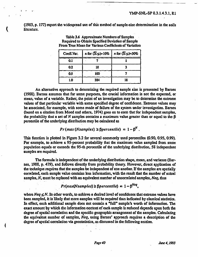
YMP-SNL-SP 8.3.1.4.3.1, R1
(1983, p. 177) report the widespread use of this method of sample-size determination in the soilsliterature.
Table 3.6 Approximate Numbers of SamplesRequired to Obtain Specified Deviation of Sample
From True Mean for Various Coefficients of Variation
Coeff.Var. n for n for
0.1 7 1
0.2 18 3
05 100 7
1.0 384 18
An alternative approach to determining the required sample size is presented by Barnes(1988). Barnes assumes that for some purposes, the crucial information is not the expected, ormean, value of a variable. Rather, the point of an investigation may be to determine the extremevalues of that particular variable with some specified degree of confidence. Extreme values maybe associated, for example, with some mode of failure of the system under investigation. Barnes(based on a citation from Mood and others, 1974) goes on to state that for independent samples,the probability that a set of N samples contains a maximum value greater than or equal to thepercentile of the underlying distribution may be calculated as
Pr (max (Nsamples)
This function is plotted in Figure 3.2 for several commonly used percentiles (0.90, 0.95, 0.99).For example, to achieve a 95-percent probability that the maximum value sampled from somepopulation equals or exceeds the 95-th percentile of the underlying distribution, 58 independentsamples are required.
The formula is independent of the underlying distribution shape, mean, and variance (Bar-nes, 1988, p. 479), and follows directly from probability theory. However, direct application ofthe technique requires that the samples be independent of one another. If the samples are spatiallycorrelated, each sample value contains less information, with the result that the number of actualsamples, N, must be replaced with an equivalent number of uncorrelated samples, Neq, thus
where Neq . In other words, to achieve a desired level of confidence that extreme values havebeen sampled, it is likely that more samples will be required than indicated by classical statistics.In effect, each additional sample does not contain a "full" sample's worth of information. Theexact amount by which the information content of each sample is reduced depends upon both thedegree of spatial correlation and the specific geographic arrangement of the samples. Calculatingthe equivalent number of samples, Neq, using Barnes' approach requires a description of thedegree of spatial correlation via geostatistics, as discussed in the following section.
Page 40 June 4,1993
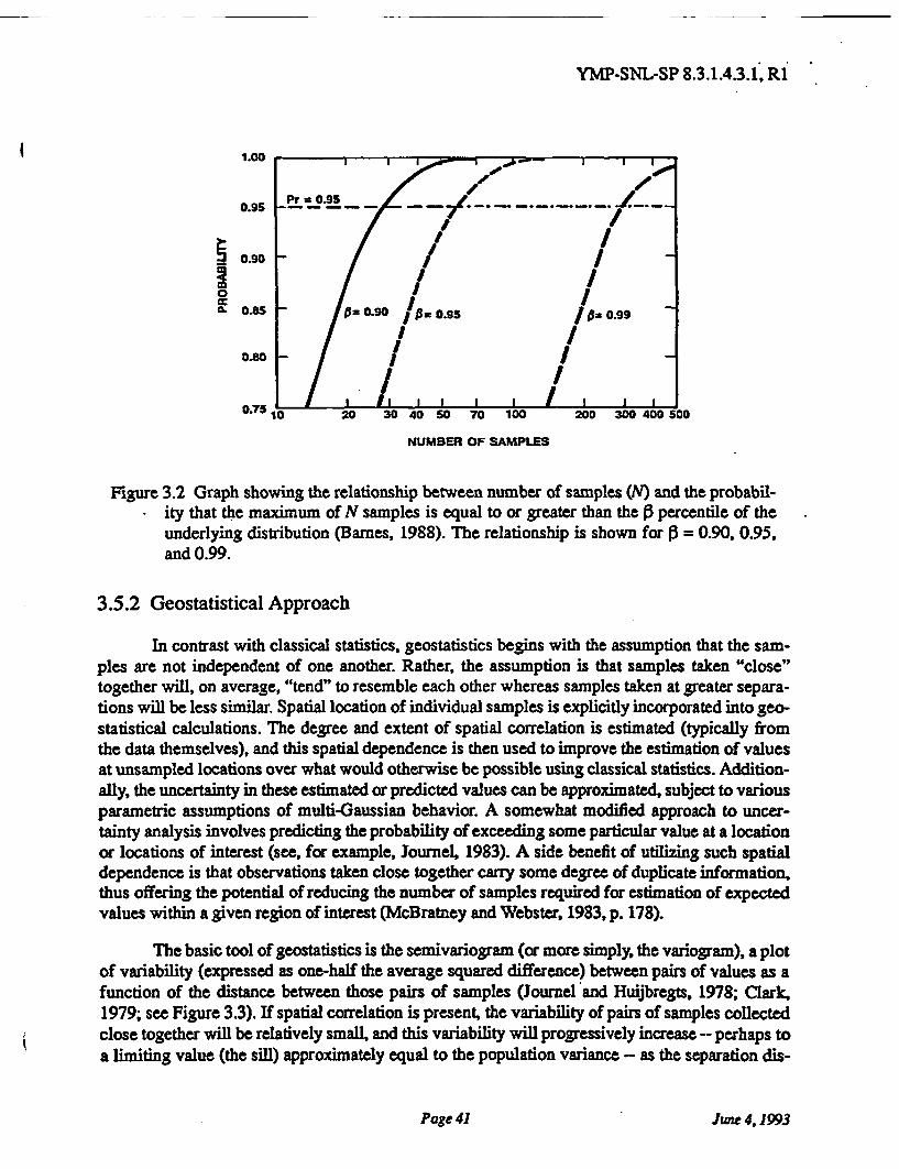
YMP-SNL-SP 8.3.1.4.3.1, R1
NUMBER OF SAMPLES
Figure 3.2 Graph showing the relationship between number of samples (N) and the probabil-ity that the maximum of N samples is equal to or greater than the percentile of theunderlying distribution (Barnes, 1988). The relationship is shown for = 0.90, 0.95,and 0.99.
3.5.2 Geostatistical Approach
In contrast with classical statistics, geostatistics begins with the assumption that the sam-ples are not independent of one another. Rather, the assumption is that samples taken "close"together will, on average, "tend" to resemble each other whereas samples taken at greater separa-tions will be less similar. Spatial location of individual samples is explicitly incorporated into geo-statistical calculations. The degree and extent of spatial correlation is estimated (typically fromthe data themselves), and this spatial dependence is then used to improve the estimation of valuesat unsampled locations over what would otherwise be possible using classical statistics. Addition-ally, the uncertainty in these estimated or predicted values can be approximated, subject to variousparametric assumptions of multi-Gaussian behavior. A somewhat modified approach to uncer-tainty analysis involves predicting the probability of exceeding some particular value at a locationor locations of interest (see, for example, Journel, 1983). A side benefit of utilizing such spatialdependence is that observations taken close together carry some degree of duplicate information,thus offering the potential of reducing the number of samples required for estimation of expectedvalues within a given region of interest (McBratney and Webster, 1983, p. 178).
The basic tool of geostatistics is the semivariogram (or more simply, the variogram), a plotof variability (expressed as one-half the average squared difference) between pairs of values as afunction of the distance between those pairs of samples (Journel and Huijbregts, 1978; Clark,1979; see Figure 3.3). If spatial correlation is present, the variability of pairs of samples collectedclose together will be relatively small, and this variability will progressively increase -- perhaps toa limiting value (the sill) approximately equal to the population variance -- as the separation dis-
Page 41 June 4,1993
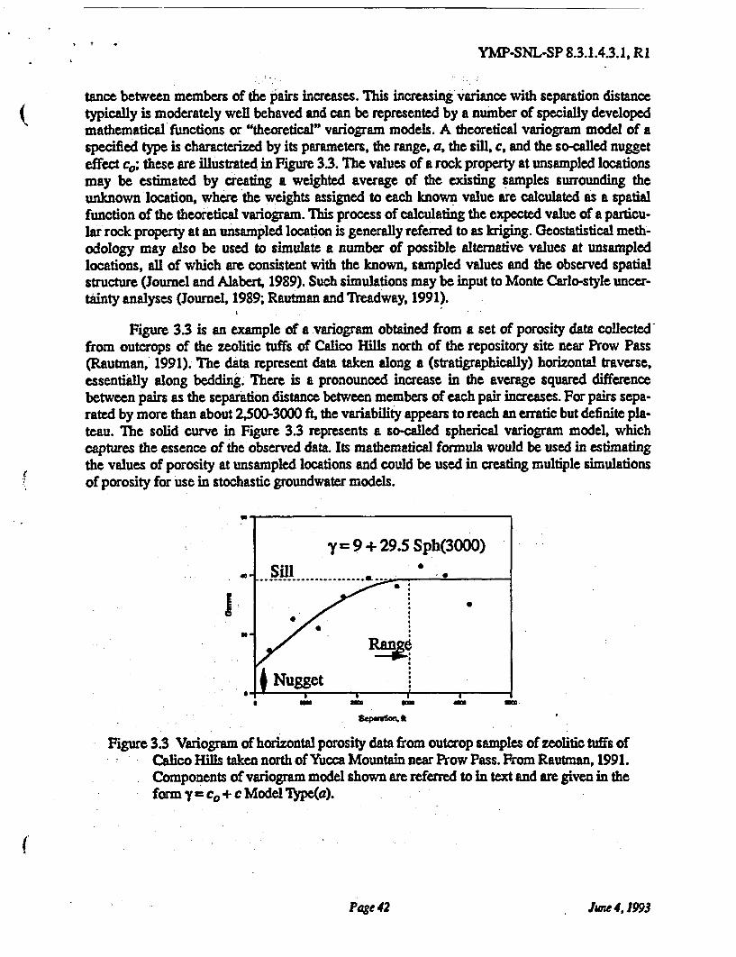
YMP-SNL-SP 8.3.1.4.3.1, R1
tance between members of the pairs increases. This increasing variance with separation distancetypically is moderately well behaved and can be represented by a number of specially developedmathematical functions or "theoretical" variogram models. A theoretical variogram model of aspecified type is characterized by its parameters, the range, a, the sill, c, and the so-called nuggeteffect these are illustrated in Figure 3.3. The values of a rock property at unsampled locationsmay be estimated by creating a weighted average of the existing samples surrounding theunknown location, where the weights assigned to each known value are calculated as a spatialfunction of the theoretical variogram. This process of calculating the expected value of a particu-lar rock property at an unsampled location is generally referred to as kriging. Geostatistical meth-odology may also be used to simulate a number of possible alternative values at unsampledlocations, all of which are consistent with the known, sampled values and the observed spatialstructure (Journel and Alabert, 1989). Such simulations may be input to Monte Carlo-style uncer-tainty analyses (Journel, 1989; Rautman and Treadway, 1991).
Figure 3.3 is an example of a variogram obtained from a set of porosity data collectedfrom outcrops of the zeolitic tuffs of Calico Hills north of the repository site near Prow Pass(Rautman, 1991). The data represent data taken along a (stratigraphically) horizontal traverse,essentially along bedding. There is a pronounced increase in the average squared differencebetween pairs as the separation distance between members of each pair increases. For pairs sepa-rated by more than about 2,500-3000 ft, the variability appears to reach an erratic but definite pla-teau. The solid curve in Figure 3.3 represents a so-called spherical variogram model, whichcaptures the essence of the observed data. Its mathematical formula would be used in estimatingthe values of porosity at unsampled locations and could be used in creating multiple simulationsof porosity for use in stochastic groundwater models.
Nugget
Figure 3.3 Variogram of horizontal porosity data from outcrop samples of zeolitic tuffs ofCalico Hills taken north of Yucca Mountain near Prow Pass. From Rautman, 1991.Components of variogram model shown are referred to in text and are given in theform y= c. + c Model Type(a).
Page 42 June 4,1993
YMP-SNL-SP 8.3.1.4.3.1; R1
The portion of the variogram most important for estimation is near the origin because thisportion of the theoretical model is what influences most heavily the estimation of nearby unsam-pled locations. Although closely spaced samples may be obtained from along drill holes, there isno particular reason to expect that the spatial structure is the same in the vertical and horizontaldirections. Table 2.2 summarizes some of the known information on correlation range and impliedvertical-to-horizontal anisotropy ratios developed by scoping studies at Yucca Mountain. Thisinformation combined with the limitations on close drill hole spacings at the site indicate thatclosely spaced samples from the Exploratory Studies Facility will be essential in modeling short-range spatial dependencies and in modeling the site itself for performance assessment and design.
3.5.3 Evaluation of Data Adequacy
Investigators working under this study will apply various of the techniques described inthis Section 3.5 to evaluate, in a preliminary manner, the adequacy of the data being collected bythis study and by other studies as described in Section 2.5. Because the actual use of the datadescribed by the Study Plan in performance assessment and design activities is the final determi-nant of "adequacy," the evaluation described in this section can only be indicative of adequacy orinadequacy. Note that the evaluation of data adequacy will be performed on an on-going and iter-ative basis (feedback loops in Figures 2.2 and 3.1). The results of early holes will be used to mod-ify plans for later holes, if required to ensure data adequacy.
As Rautman and Flint (1992) have noted, it is not entirely clear what constitutes a popula-tion at Yucca Mountain for statistical purposes (see also Section 2.1.2). Rautman and others(1991) obtained information that suggests that the microstratigraphic units shown in Figure 1.2may be the appropriate level of subdivision. Simple graphical displays (see Rautman and Flint,their Figure 3) of the framework properties measured by this study (Table 3.4), plotted as a func-tion of drill hole depth and matched with the more descriptive geologic information obtained fromcore logging, will be used to help identify what may constitute a useful statistical population. Fordown-hole intervals that are relatively discrete from other intervals, application of techniquesfrom classical statistics (Section 3.5.1) may yield good indications of data adequacy.
Other intervals, however, simply cannot be treated as statistically homogeneous popula-tions. This is one of the underlying assumptions of this study as discussed in Section 2.1.2. Sam-ples and laboratory measurements from these intervals will be evaluated using geostatisticaltechniques, such as the variogram analysis described in Section 3.5.2, to ensure that samples arebeing spaced closely enough to capture most of the spatial variability. The usefulness of vario-gram analysis is that the range of the variogram (a, see Figure 33) provides an estimate of themaximum intersample distance. The "optimal" intersample distance will be less, of course. Therelative nugget effect, co, or apparent y-intercept of the variogram model, provides additionalinformation on sample spacing. A large nugget relative to the overall sill, suggests that there is agreat deal of unresolved spatial variability. Conversely, a well defined variogram model with a rel-atively small nugget effect suggests that overall variability is well modeled, especially if there areeven a few pairs of samples at very short spacings that confirm the low-nugget model. Becausethe intent of initial sampling efforts for this study is to provide data on roughly a meter-scale ver-tically (about one sample per 1.5 m; Section 2.2.3), the results of the first one or two drill holesshould provide strong evidence as to adequacy of these plans. Additional, if slightly more qualita-
Page 43 June 4, 1993
YMP-SNL-SP 8.3.1.4.3.1, R1
tive information, will be available at very short spacings from geophysical logs. Geophysical logs(Section 3.3) will also be used to evaluate the potential for bias being introduced in intervals thatcould not be sampled for one reason or another. Large residual variability, as indicated by a largenugget effect, on a less-than-meter scale probably cannot be addressed simply by routine sam-pling and testing. Should these types of variogram patterns be suggested by the data, otherapproaches, yet to be determined, will need to be investigated. Such variability probably wouldindicate a "process" type of issue, and investigators working under this study would need to coor-dinate a resolution with the appropriate process-oriented study, as discussed in Sections 1.1 and2.5.
Evaluation of drill hole spacing adequacy will be performed using the same techniquesdescribed in the preceding paragraph. Horizontal variograms will be constructed for variousstratigraphic increments. Large nugget effects observed in these analytic plots would suggest thatdrill holes are being spaced at intervals that are too large compared with the spatial variability ofthe rock properties of interest. Because the scoping data obtained to date (Section 2.2.2) suggeststhat this is, in fact, the case, data taken from the (largely) stratigraphically horizontal "exposure"of tuffs from Topopah Spring Member and Calico Hills unit in the Exploratory Studies Facilitywill be added to the evaluation data set. It then should be possible to define the range of spatialcorrelation using these additional samples.
3.5.4 Assessment of Laboratory Results Obtained by Different Laboratories
In general, this study will not be responsible for evaluating the measurements of rockproperties obtained by different laboratories, since the majority of properties are determined by anappropriate process-oriented study. However, Table 3.5 does indicate that some properties are tobe measured by more than one laboratory. Because use of these data in performance assessmentand design activities requires a certain degree of compatibility for measurements of what, ostensi-bly, are the "same" material property, there is a potential for inter-laboratory differences to con-found the issue. If the samples that are subjected to multiple-laboratory measurement areindependent, there is an extensive body of statistical literature that can be used to assess the exist-ence and extent of inter-lab variability. If, however, as is likely the case for geologic materials, thesamples are not independent observations of the same statistical population, these classical tech-niques, such as analysis of variance, are likely to give misleading results.
This study proposes to address the issue of inter-laboratory variability, if appropriate,through the type of geostatistical analysis described in Section 3.52, above. If (for example)porosity values measured by one laboratory give essentially the same variogram model as sam-ples tested by a different laboratory, or if the combination of two (laboratory) data sets formsessentially the same pattern as the sets do individually, then it appears likely that the laboratoryresults are essentially equivalent. Any differences in mean values observed in samples tested byvarious laboratories, which form the basis for classical statistical evaluations of inter-lab variabil-ity, presumably reflect real differences in the material tested by each lab. Such differences proba-bly originate in the locations of the original samples.
Page 44 June 4,1993
YMP-SNL-SP 8.3.1.4.3.1, R1
3.6 Quality Assurance Requirements and the Experiment Procedure
The major portion of the activity in the study is quality affecting as indicated on theapproved Quality Assurance Grading Report (QAGR) S1232221A. Planning and scoping activi-ties are not considered non-quality affecting, but are of special programmatic importance as indi-cated on a separate QAGR (S1232221B). All work will be performed in accordance with the SNLQuality Assurance Program Description. Scientific notebooks and technical procedures will beused to describe the work required to fulfill the objectives of this Study Plan (Table 3.1).
3.7 Accuracy and Precision of Results
Much of the information obtained by this study is interpretive in nature. As such, the reli-ability of this information depends highly upon the experience of the principal investigator(s) andother scientific staff involved in the collection and analysis of the data. As discussed in Section2.4.3, determination of stratigraphic contacts, particularly gradational ones, is subjective. In manycases, consistency of determination (a surrogate for precision?) is more important to the resolu-tion of geologic problems than the correctness of a stratigraphic pick, especially when "correct" isill-defined and indeterminate. Most such gradational intervals that would be subject to differinginterpretations are of relatively small extent compared with the overall stratigraphic unit underconsideration (compare the roughly 30-foot gradational base of the Tiva Canyon member com-pared with the 450-ft extent of the overall unit; Rautman and Flint, 1992). Most of the subjectiveand interpretive information to be obtained by this study is easily recognized as such. Experiencedpersonnel are likely to note unusual uncertainties while describing core and to review geologiclogs for consistency between drill holes (or with known outcrops).
Table 3.2 lists the main geologic and engineering parameters to be obtained directly by theSystematic Drilling Program. The principal quantitative measurements to be obtained are thethickness and depths within the hole of certain features of interest. Under optimal conditions suchas 100-percent core recovery and intact (non-fractured) core, depth and thickness measurementsare easily made to ±0.1 ft (a few cm). However, depth measurements are tied to the driller's mea-surement of hole depth at drilling breaks to recover core. These latter measurements are rarelyaccurate to within one foot (0.3 m), particularly in deep holes. Also, optimal core condition fre-quently do not exist. Core maybe be left at the bottom of a hole to be destroyed upon reentry or tobe picked up with the next core run. Core may be lost (ground up) during drilling. Highly frac-tured intervals may not be reconstructible at the surface to the "intact" in situ dimensions for mea-surement. The accuracy of measurements obtainable under these conditions may only be to within5 or 10 feet (2 or 3 m). These inherent limitations on the accuracy and precision of these quantita-tive measurements are judged acceptable except in intervals of severe core loss. In such instances,available core information will be combined with other information, such as geophysical logs, toarrive at the best possible depth measurement.
There are also limitations on the ability to determine the exact path of a borehole under-ground. Although holes for the Systematic Drilling Program will be surveyed using down-holeinstrumentation, unique hole conditions may affect the survey results. In summary, it is probablypossible to locate a given feature to within roughly 10 feet (3 m) of its true spatial position, withsmaller errors nearer the topographic surface and larger errors at greater depths. Errors of this
Page 45 June 4,1993
YMP-SNL-SP 8.3.1.4.3.1, R1
magnitude at repository depths (greater than 600 ft or 200 m by regulation) are on the order of 2percent vertically and significantly less horizontally compared with repository dimensions of2,000 to 10,000 ft (600-3,000- m). Quantitative requirements for spatial accuracy are difficult todetermine, however SCP Table 8.3.2.2-5 specifies accuracies of 10 to 100 ft (3-30 m) for spatialtype variables.
Other information, particularly the laboratory determinations of physical rock properties,is relatively objective and mechanistic by comparison with the interpretation of contacts betweenunits and faults. The accuracy and precision of these data will depend principally upon the speci-fications for data acquisition and reduction outlined in the experiment procedure and technicalprocedures used to conduct the measurements. The precision of the bulk matrix properties listedin Table 3A is estimated at approximately 0.25 to 0.5 percent. Permeability measurements areprobably precise to a factor of 2 to 5. The limits of any measurement in representing block-scaleproperties is discussed in Section 2.4.3.
It is useful to note that the "accuracy and precision" of all data obtained from drill holesamples is somewhat limited in terms of their absolute location in space by the sampling and mea-suring constraints discussed in the preceding paragraphs. Additionally, the uncertainties that arisein estimating rock properties at unsampled locations generally far outstrip the measurementuncertainty of laboratory testing. Various geostatistical and other techniques exist for assessingthe impact on these characterization uncertainties on the results of performance calculations (see,for example, Journel, 1989; Rautman and Treadway, 1991). Discussion of this aspect of uncer-tainty assessment is far beyond the scope of this Study Plan.
3.8 Range of Expected Results
Because the majority of the parameters to be obtained by the Systematic Drilling Programare qualitative in nature, the concept of a "range" of values really does not apply in manyinstances. The data frequently are descriptive in a verbal sense. With respect to the more quantita-tive of the descriptive variables to be measured, depths and thicknesses are limited to the totaldepth of the drill holes, which are expected to range between about 2,000 and 2,600 feet (600-800m). Core recovery is expected to range between zero and 100 percent; the mean core recovery ofall information contained in the Project Site and Engineering Properties Data Base is roughly 80-85 percent. RQD values likewise range from zero to 100, and are essentially a percentage recov-ery of 'good" core (not highly fractured and broken). 1
The ranges of values expected for the laboratory rock property determinations to be mea-sured by this study are given in Table 3.4. The ranges of values expected for other laboratory rockproperties to be measured on core samples from the Systematic Drilling Program, but which aremeasured by other site characterization studies are tabulated in the study plans for the appropriatetesting activities (see Table 3.5).
1. The Project has not collected RQD measurments in the past Instead, a composite quantity known as CIor core index has be measured instead; the two quantities are not directly comparable.
Page 46 June 4,1993
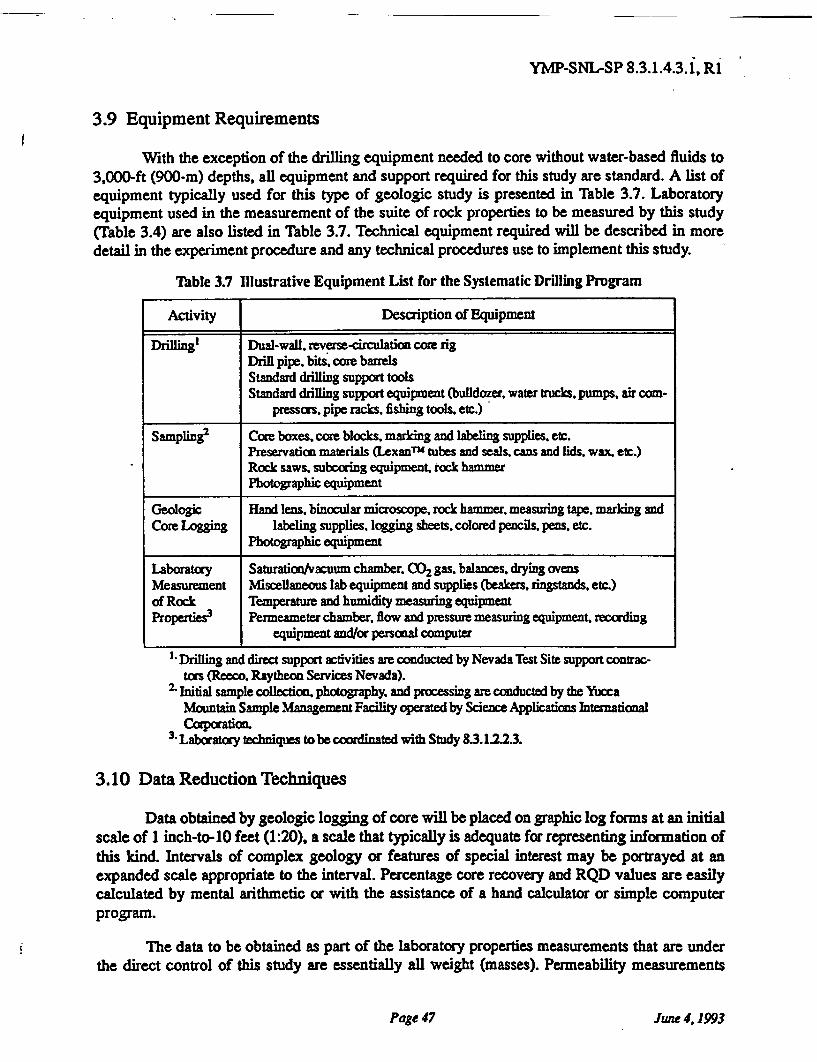
YMP-SNL-SP 8.3.1.4.3.1, R1
3.9 Equipment Requirements
With the exception of the drilling equipment needed to core without water-based fluids to3,000-ft (900-m) depths, all equipment and support required for this study are standard. A list ofequipment typically used for this type of geologic study is presented in Table 3.7. Laboratoryequipment used in the measurement of the suite of rock properties to be measured by this study(Table 3.4) are also listed in Table 3.7. Technical equipment required will be described in moredetail in the experiment procedure and any technical procedures use to implement this study.
Table 3.7 Illustrative Equipment List for the Systematic Drilling Program
Activity Description of Equipment
Drilling Dual-wall, reverse-circulation core rigDrill pipe. bits, core barrelsStandard drilling support toolsStandard drilling support equipment (bulldozer, water trucks, pumps, air com-
pressors, pipe racks. fishing tools, etc.)
Sampling Core boxes, core blocks, marking and labeling supplies. etc.Preservation materials (Lexan tubes and seals, cans and lids, wax. etc.)Rock saws, subcoring equipment, rock hammerPhotographic equipment
Geologic Hand lens, binocular microscope, rock hammer measuring tape, marking andCore Logging labeling supplies, logging sheets, colored pencils, pens, etc.
Photographic equipment
Laboratory Saturation/vacuum chamber. gas, balances, drying ovensMeasurement Miscellaneous lab equipment and supplies (beakers, ringstands. etc.)of Rock Temperature and humidity measuring equipmentProperties3 Permeameter chamber, flow and pressure measuring equipment, recording
equipment and/or personal computer
1 Drilling and direct support activities are conducted by Nevada Test Site support contrac-tors (Reeco. Raytheon Services Nevada).
2 Initial sample collection, photography, and processing are conducted by the YuccaMountain Sample Management Facility operated by Science Applications IntenationalCorporation.
3 Laboratory techniques to be coordinated with Study 8.3.1.223.
3.10 Data Reduction Techniques
Data obtained by geologic logging of core will be placed on graphic log forms at an initialscale of 1 inch-to-10 feet (1:20), a scale that typically is adequate for representing information ofthis kind. Intervals of complex geology or features of special interest may be portrayed at anexpanded scale appropriate to the interval. Percentage core recovery and RQD values are easilycalculated by mental arithmetic or with the assistance of a hand calculator or simple computerprogram.
The data to be obtained as part of the laboratory properties measurements that are underthe direct control of this study are essentially all weight (masses). Permeability measurements
Page 47 June 4,1993
YMP-SNL-SP 8.3.1.4.3.1, R1
involve measurement of mass, but also of pressure and time. These weights are converted into thebulk properties and hydrologic state variables (Table 3.4) through simple algebraic relationships,and the computations are easily performed with a hand calculator or Lotus -style computerspreadsheet. Permeability is likewise computed from simple, if slightly more complicated, alge-braic relationships.
The synthesis and interpretation of these results and other data collected as part of thisstudy depends upon the experience of the principal investigator(s) and support staff. Evaluation ofthe spatial structure as revealed by laboratory rock properties information will be performedthrough the use of both classical and geostatistical methods. These techniques are described inwidely used textbooks and other references (Journel, 1978; Clark, 1979; Isaaks and Srivastava,1989).
3.11 Representativeness of Results
The Systematic Drilling Program will acquire samples and data from the repository blockand vicinity, both areally and from the topographic surface to below the water table. This informa-tion will be combined with data obtained by other studies from the same three-dimensional vol-ume of rock. These studies include the drilling-related programs listed in Table 2.1, but will alsoinclude surface and Exploratory Studies Facilities activities such as will be conducted underStudy 8.3.1.4.2.1 (Characterization of Stratigraphic Units) and 8.3.1.4.2.2 (Characterization ofStructural Features). Drill hole locations for the integrated drilling program have been selected toprovide both areal coverage at approximately 2,500- to 3,000-ft (750-900 m) intervals and detailsof the spatial structure at smaller separations. Down-hole samples will provide vertical coverageat roughly one-meter spacings.
To the extent that these combined studies provide samples from an area that covers theentire repository environment, the data collected are - by one definition - representative. Muchdiscussion has focused on the accuracy of expected values, another definition of representative.Barnes (1988) provides an interesting discussion of another alternative approach to the issue: thatthe spatial "average" value is not the objective, but rather the purpose of site characterization is torealistically reflect the extreme values of a variable. The application of geostatistical techniques tothe data obtained from the integrated drilling program will provide several quantitative estimatesof representativeness. Risk-qualified estimates (Journel, 1983) of the various rock properties canbe provided, if required
3.12 Performance Goals and Confidence Limits
The performance allocation process has identified the performance goals and confidencelevels required to resolve the key issues addressed by the study plan. These performance goalsand associated confidence limits of parameters to be provided by this study are summarized in rel-atively high-level "model elements" of Yucca Mountain in SCP Tables 83.1.4-1 and 83.1.4-2.More detailed descriptions of performance goals and confidence intervals for individual parame-ters as required by SCP activities using these parameters are found in many locations throughoutthe SCP (Table 3.8). The majority of parameters obtained by the Systematic Drilling Programgenerally are those related to rock-unit contacts and configurations, fractures and faults, and those
Page 48 June 4,1993
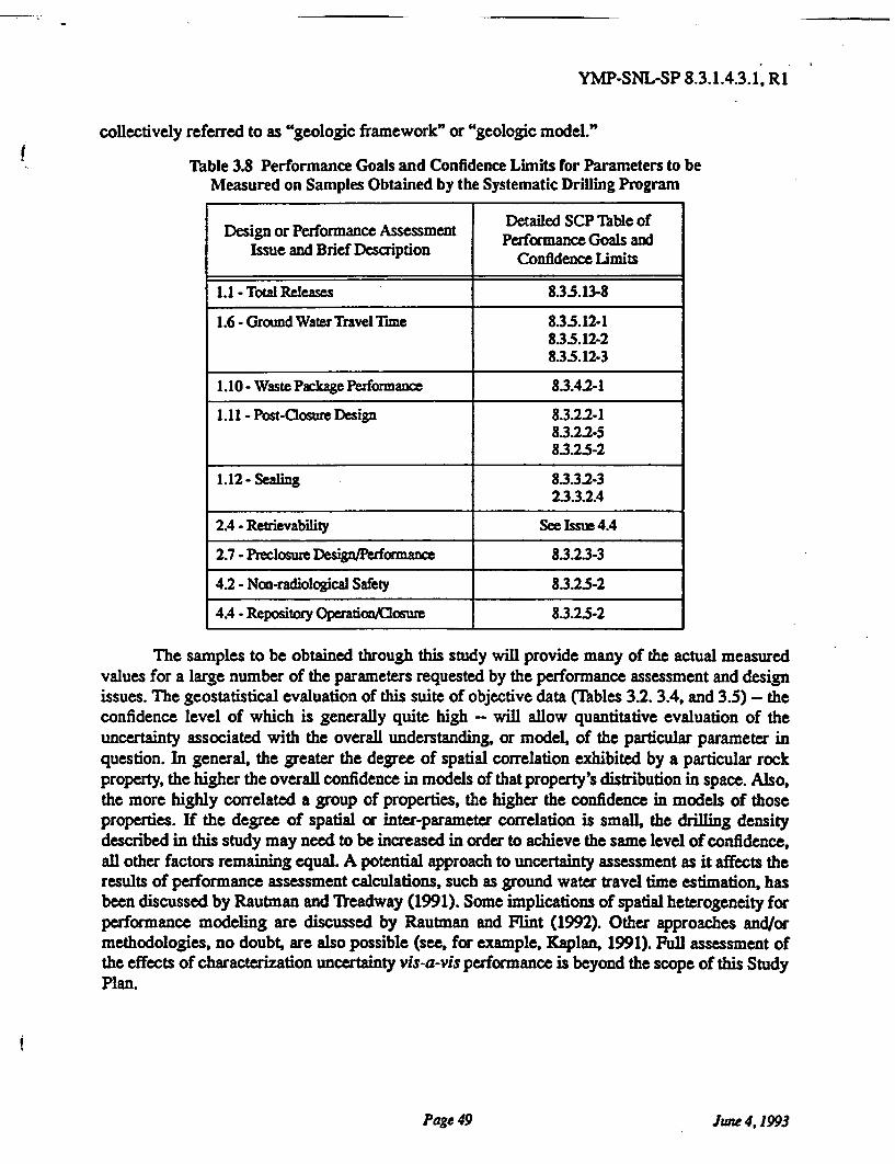
YMP-SNL-SP 8.3.1.4.3.1, R1
collectively referred to as "geologic framework" or "geologic model."
Table 3.8 Performance Goals and Confidence Limits for Parameters to beMeasured on Samples Obtained by the Systematic Drilling Program
Detailed SCP Table ofDesign or Performance AssessmentIssue and Brief Description Performance Goals andConfidence Limits
1.1 - Total Releases 835.13-8
1.6 - Ground WaterTravel Time 8.5.12-1835.12-2835.12-3
1.10 - Waste Package Performance 8.3.42-1
1.11 - Post-Closure Design 8.3.22-18.3.2.2-58.3.25-2
1.12- Sealing 8.3.3.2-32.3.3.2.4
2.4 - Retrievability See Issue 4.4
2.7 - Preclosure Design/Performance 8.3.2.3-3
4.2 - Non-radiological Safety 8.3.25-2
4.4 - Repository Operation/Closure 8.3.25-2
The samples to be obtained through this study will provide many of the actual measuredvalues for a large number of the parameters requested by the performance assessment and designissues. The geostatistical evaluation of this suite of objective data (Tables 3.2. 3.4, and 3.5) - theconfidence level of which is generally quite high - will allow quantitative evaluation of theuncertainty associated with the overall understanding, or model, of the particular parameter inquestion. In general, the greater the degree of spatial correlation exhibited by a particular rockproperty, the higher the overall confidence in models of that property's distribution in space. Also,the more highly correlated a group of properties, the higher the confidence in models of thoseproperties. If the degree of spatial or inter-parameter correlation is small, the drilling densitydescribed in this study may need to be increased in order to achieve the same level of confidence,all other factors remaining equal. A potential approach to uncertainty assessment as it affects theresults of performance assessment calculations, such as ground water travel time estimation, hasbeen discussed by Rautman and Treadway (1991). Some implications of spatial heterogeneity forperformance modeling are discussed by Rautman and Flint (1992). Other approaches and/ormethodologies, no doubt, are also possible (see, for example, Kaplan, 1991). Full assessment ofthe effects of characterization uncertainty vis-a-vis performance is beyond the scope of this StudyPlan.
Page 49 June 4,1993
YMP-SNL-SP 8.3.1.4.3.1, R1
4.0 APPLICATION OF RESULTS
The results of this study will be used both directly and indirectly in a large number ofdesign and performance assessment issues. In addition, there are a large number of site character-ization studies that depend upon the results of this study, typically for sample materials to supporttesting activities.
4.1 Application of Results of Resolution of Performance Assessment Issues
A primary use of the results of this study is to resolve performance issues related to thetwo "geologic" or "site-oriented" regulatory licensing criteria: (1) the pre-waste emplacementground water travel time requirement, and (2) the total systems radionuclide release requirements.These are Issues 1.1 and 1.6 in Table 1.2. These and most of the other issues listed in the tabledepend upon a physical description of the site or upon a modeling interpretation of the site basedupon such a description. A well documented, accurate, geometric representation of the YuccaMountain site is essential to resolving virtually all performance issues. This is reflected at a highlysimplified level in the majority of the Information Needs listed in Table 1.2 as "site informationrequired for ...." Some "components" of the geometric description of Yucca Mountain (the "siteinformation" of the Information Needs) are listed in Table 3.2.
In addition to a geometric description of the Yucca Mountain site, quantitative assessmentof ground water travel time, radionuclide release rates, and other performance assessment mea-sures require input descriptions of physical rock properties (rock characteristics) to allow numeri-cal calculations. These input descriptions of material properties are required on a wide variety ofscales and levels of detail. At one level performance assessment calculations may only require amean and variance for, say, hydraulic conductivity. At another level, calculations may be basedupon a detailed, three-dimensional representation of a number of cross-variable- and spatially cor-related rock properties in the immediate vicinity of some deterministic (geometric) feature such asthe Ghost Dance fault. Some of the "rock characteristics" that result from this study are listed inTables 3.2 and 3.4. However, the full variety of "site information" (which term really reflects andencompasses various combinations and the interplay of such rock characteristics) required toresolve all performance assessment issues is nearly as wide as the entire Site CharacterizationPlan, and is certainly beyond the scope of this Study Plan.
Although detailing how the information derived from this study will be applied to the res-olution of all performance assessment issues is beyond the scope of this document, it is clear thata unifying means of understanding that application is through the concept of models.' The fullthree-dimensional, computer-based, geologic and rock characteristics models of the site, whicheventually will incorporate the results of this and other site characterization studies, will representboth the geometric framework of the mountain (based on identifiable stratigraphic units) and thecontinuously variable rock-properties (based on interpolation and/or simulation of measured val-ues). Because site characterization data are, themselves, simply a collection of measurements or
1. Models, as used in this section, includes both deterministic "best estimate" models and multiple stochasticsimulations or "images" as described by Journel and Alabert (1989). The word implies a description ofgeology and other rock characteristics and not a hydrologic or flow model.
Page 50 June 4, 1993
YMP-SNL-SP 8.3.1.4.3.1, R1
other observations, the immediate results of this study simply constrain the models, which are the"useful" results.
Use of three-dimensional geometric models is relatively intuitive: knowing where thingsare is a fundamental basis for understanding how a system behaves. The utility of the rock charac-teristics models is more complex and tends to be application specific. However, it should also beintuitive that a detailed three-dimensional representation can be simplified to meet the needs of awide variety of users. Two-dimensional cross-sections, one-dimensional profiles, and even non-dimensional (spatial dimensions) distributions of values can be extracted as required. Further-more, the simplifications are easily understood in their original context, which can add to theircredibility for certain purposes. A simplified, one-dimensional example of the application of thestochastic-simulation approach to performance assessment modeling as applied to Yucca Moun-tain, in which descriptive rock characteristics models are coupled to a hydrologic flow model, hasbeen presented by Rautman and Treadway (1991).
4.2 Application of Results of Resolution of Design Issues
Application of the results of this study in resolving design issues is most directly under-stood through the concept of the geometric model outlined immediately above. If the potentialrepository is to be constructed in a certain portion of the Topopah Spring Member of the Paint-brush Tuff, then knowing where that unit is in space is critical to the design of the repository. Theneed for this type of information has been expressed repeatedly as "site information needed for... " in the design-related information needs of Table 1.2. Three-dimensional models of the site arerequired for engineering design of the underground facilities, the engineered barrier system, shaftsand ramps, and the Exploratory Studies Facility.
Much of the discussion of three-dimensional rock characteristics models previously pre-sented in terms of performance assessment (Section 4.1) applies equally well to the more detailedaspects of design calculations. Numerical representations of physical rock properties are requiredto support design computations of drift stability, thermal loading, heat dissipation, and similaraspects of repository design. Detailed discussion of exactly which models will be created and howthey will be used based on the information resulting from this study and other studies that will testsamples obtained by this study is obviously beyond the scope of this Study Plan.
4.3 Application of Results to Other Site Characterization Studies
In addition to the application of results from the Systematic Drilling program by activitiesin the areas of performance assessment and design, a wide variety of other site characterizationstudies (Table 1.1) depend upon this study as well. Significant discussion of the direct use ofphysical sample materials and the drill holes themselves from the Systematic Drilling Program ispresented in Sections 1.3, 2.1.1, 2.5, 3.3, and 3.4 of this Study Plan.
It should be noted the evaluation of information being obtained by these various studies interms of adequacy in characterizing the site (Section 3.5) is a unifying theme pursued by thisstudy. Information obtained from holes drilled early in the program will be used to evaluate and tomodify ongoing site characterization studies, if required. Preliminary estimates of spatial correla-
Page 51 June 4,1993
YMP-SNL-SP 8.3.1.4.3.1, R1
tion (Table 2.2) will be confirmed or revised. Holes planned by studies such as the SystematicDrilling Program itself or other components of the integrated drilling program (Table 2.1) may berelocated or additional drill holes scheduled. Sampling programs being conducted by various SCPstudies (Table 1.1; including this study) may need to be modified based on such early results inorder to prevent significant over- or undersampling of the site.
Other site characterization studies will use portions of the information as well. A detailed(although not necessarily complete) discussion of the relationships between some site character-ization results and the relevant design and performance assessment issues is presented in SCP sec-tion 8.3.1.4 and specifically in SCP Table 83.1.4-1.
Page52 June 4,1993
YMP-SNL-SP 8.3.1.4.3.1, R1
5.0 SCHEDULE AND MILESTONES
The work planned as part of this study is composed of one formal (SCP) activity. How-ever, this activity, the Systematic Drilling Program, may be thought of as a sequence of fiverepeating tasks or subactivities (Figure 3.1).The schedule for the Systematic Drilling Program isstrongly influenced by the logistics of drilling, a notoriously difficult type of endeavor for whichto maintain a schedule. However, because many similar drilling efforts are planned as part of sitecharacterization, difficulties encountered in drilling holes for the Systematic Drilling Program arelikely to cause similar problems in other programs. Thus, whereas the entire repository schedulemight be delayed by unanticipated logistical problems, it is unlikely that the Systematic DrillingProgram would be the unique cause of that delay.
Because of the intimate and-inescapable tie between the Systematic Drilling Program andthe repository block, it is essential that most, if not all, of the Systematic Drilling Program becompleted in time to provide input to advanced conceptual design. If an insufficient and/or inac-curate geologic model of the site is used in advanced conceptual design, some unpredictable frac-tion of those design efforts might need to be redone. A major redesign effort might require delaysin the license application design, if the errors were significant enough. Propagation of significantdesign delays probably would result in delaying the formal license application, and potentially thestart of construction and/or operation of a repository. Separate from the issue of schedule delaysdue to inadequate geologic models of the site is a concern with early construction of facilities(such as the Exploratory Studies Facility) that technically are part of site characterization, butwhich are intended to be incorporated into the ultimate repository facility. Without informationfrom certain critical drill holes of the Systematic Drilling Program, various features of the Explor-atory Studies Facility, such as test levels and breakout rooms, cannot necessarily be located accu-rately enough to allow construction. In a worst case scenario, mislocating major engineeredfeatures of the ESF/repository might limit the usefulness of those facilities for their intended pur-poses.
5.1 Scheduling Relative to Other Studies
5.1.1 Drilling
The relationship of the Systematic Drilling Program to other studies that involve drillingis constrained by the availability of drilling equipment. The proposed, tentative sequence of drillholes for this study is discussed below in Section 5.2. Logistical integration of Project drillingactivities generally will be accomplished by interspersing drill holes from different programs inan evolving actual field schedule. Examples of other major drilling programs include RegionalGround-Water Flow System (Study 8.3.1.2.1.3), Unsaturated Zone Percolation (Study8.3.1.2.2.3), Saturated-Zone Ground-Water Flow System (Study 83.1.23.1), and Characteriza-tion of ... Stratigraphic Units (Study 8.3.1.4.2.1) (see Table 2.1). The principal impact of theseother drilling efforts on the Systematic Drilling Program would be to delay (or accelerate) holes ofthe SD- program depending upon the execution of the other drilling efforts. Overall integration ofthe Project drilling schedule is the subject of SCP Activity 8.3.1.4.1.1, which is the responsibilityof the Yucca Mountain Site Characterization Project Office.
Page 53 June 4.1993
YMP-SNL-SP 8.3.1.4.3.1, R1
Initiation of drilling for any particular hole (SD- program or not) is contingent upon com-pletion of the previously scheduled hole and operational availability of the drilling equipment.Nevada Test Site drilling procedures require periodic, comprehensive rig certification evaluations;these are estimated to require 30 days of downtime approximately once a year. Some of the otherdrilling studies (notably Unsaturated Zone Percolation) currently call for an extended period ofdown-hole testing. Retaining the specialized dual-wall, reverse-circulation drilling equipment foran extended period of down-hole testing for periods of up to several years for monitoring and test-ing purposes is obviously unsatisfactory to all parties. The main drilling equipment will bereleased upon completion of actual drilling, and a subsidiary drill rig and equipment provided tosupport hole instrumentation and testing.
Because many contingencies are involved in the Project drilling effort, the drilling sched-ule will be continually revised. It is impossible to speculate regarding specific events and situa-tions that may need to be addressed over the course of site characterization drilling. However,there will always be numerous options for the "next" hole should a particular rig be delayed orbecome available unexpectedly. Each major Project drilling program (Table 2.1) consists of asuite of holes that are intended to accomplish the goals of the relevant study or investigation. Sitedrilling is a major aspect of site characterization, and Project-level decisions will be required withrespect to drill hole prioritization and scheduling in light of the then-current limitations of man-power, budget, equipment availability, and programmatic needs for samples and information.However, it is clear that major delays anywhere in the drilling effort would have significanteffects on the Yucca Mountain schedule for advanced conceptual and license application design.Potential impacts include delays in submittal of the license application.
5.1.2 Exploratory Studies Facility
The exact relationship of this study to other studies to be conducted in the ExploratoryStudies Facility is unclear because of the evolving schedule and plans for the Exploratory StudiesFacility. Accordingly, no specific description of these relationships is possible. Initiation of sur-face-based work for this study is not dependent upon the plans or schedule for the ESF.
Generally, the sampling to be conducted by this study in the Exploratory Studies Facilityis anticipated to be along the long main drifts of the ESF. Sampling anticipated by this studywould be "incidental" sampling, and consist of removing a small core plug a few inches (cm) longor a small hand specimen at regular intervals along accessible workings (see Section 2.2.4). Therequirements for location and spacing of samples is sufficiently flexible that any conflicts that areidentified as plans for other ESF testing activities are finalized can be resolved simply by not col-lecting within a to-be-agreed-upon standoff distance from the other test locations. It is unlikelythat the testing to be performed by this study on samples from the Exploratory Studies Facilitywould be compromised by any anticipated testing in the ESF.
5.13 Sampling and Laboratory Testing
A number of SCP studies (Table 1.1) are wholly or partially dependent upon the System-atic Drilling Program for sample materials on which to conduct various types of laboratory tests(Table 3.5). The intent of most, if not all, of testing studies listed in Table 1.1 is to provide early
Page 54 June 4,1993
YMP-SNL-SP 8.3.l.4.3.1, R1
input to advanced conceptual design, followed by more detailed information to be used in thelicense application design. Obviously, testing activities that are predicated upon the availability ofcertain samples cannot be undertaken until those physical materials are available. In similar fash-ion, any performance assessment or design activities that depend upon the results of this testingcannot begin or progress beyond a certain stage without those test data. Any performance assess-ment or design analyses that are conducted on the basis of preliminary information thus is subjectto revision once more complete information is available.
Although it is not possible to indicate specific temporal relationships between the System-atic Drilling Program and the laboratory-testing activities that depend upon the drilling programfor samples (Table 3.5), the unique, close tie between this study and the repository block and thelogic diagrams of Figures 2.2 and 3.1 do have some qualitative implications for scheduling. Spe-cifically, it is important to start some holes of the site-specific Systematic Drilling Program assoon as possible. Early initiation of the Systematic Drilling Program will produce samples early insite characterization that can be distributed to the testing studies that require them through theprocess described in Figure 2.2. Thus, physical properties testing can begin early, with the earlyresults forming the basis for a crude-but-first-pass evaluation effort to identify any gross discrep-ancies between the Project's pre-site characterization understanding of the site and the new data.Additionally, the descriptive information from the first drill holes (Table 3.2) will provide signifi-cant information to confirm or revise the pre-site characterization understanding of the overall,immediate repository block. To accentuate the areal-coverage aspect of this Study Plan (see Sec-tion 2.2.2), the first several holes will be located in diverse geographic portions of the study area(Figure 1.3). Although the specific sequence described in Section 5.2 is subject to change as sitecharacterization progresses, these philosophical concepts have been incorporated into the sched-ule as described below.
5.2 Schedule and Milestones
The schedule for this study is based upon approval of the study plan and completion of rel-evant procedures at least thirty days before work begins. Delays related to the approval of thestudy plan and associated documents, such as readiness reviews, job packages, funding authoriza-tions, and so on will have corresponding effects on the execution of the study.
The preliminary proposed sequence of drill holes (SD prefix) for this study is shown inFigure 5.1. This sequence is subject to modification as the drilling program progresses and infor-mation is gained from the initial drill holes. Also, the sequence is "incomplete," in that itaddresses only holes of the Systematic Drilling Program. In practice, SD-prefix holes will beinterspersed with drill holes officially "belonging" to other SCP Studies (see also discussion inSections 2.5 and 3.1). The sequence may also be impacted by the number of drill rigs available.Figure 5.1 is constructed as if each SD drill hole were conducted in simple sequence, one after theother with no gaps. The availability of more than one piece of drilling equipment may allow morethan one SD hole to be in progress at any time.
A description of the interrelationships of each of the five-task sequence of the SystematicDrilling Program is presented in the discussion associated with Figure 3.1. These repeatingsequences of work activities are portrayed on a tentative, and idealized, timeline in Figure 5.2.
Page 55 June 4,1993
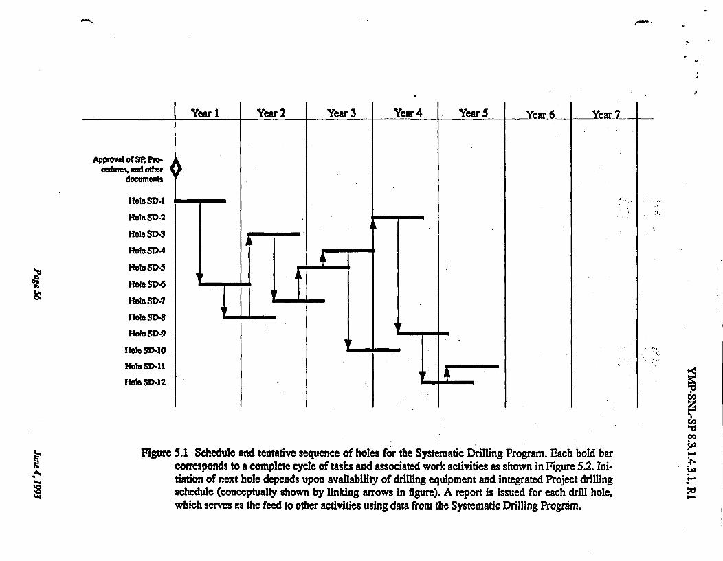
Figure 5.1 Schedule and tentative sequence of holes for the Systematic Drilling Program. Each bold barcorresponds to a complete cycle of tasks and associated work activities as shown in Figure 5.2. Ini-tiation of next hole depends upon availability of drilling equipment and integrated Project drillingschedule (conceptually shown by linking arrows in figure). A report is issued for each drill hole,which serves as the feed to other activities using data from the Systematic Drilling Program.
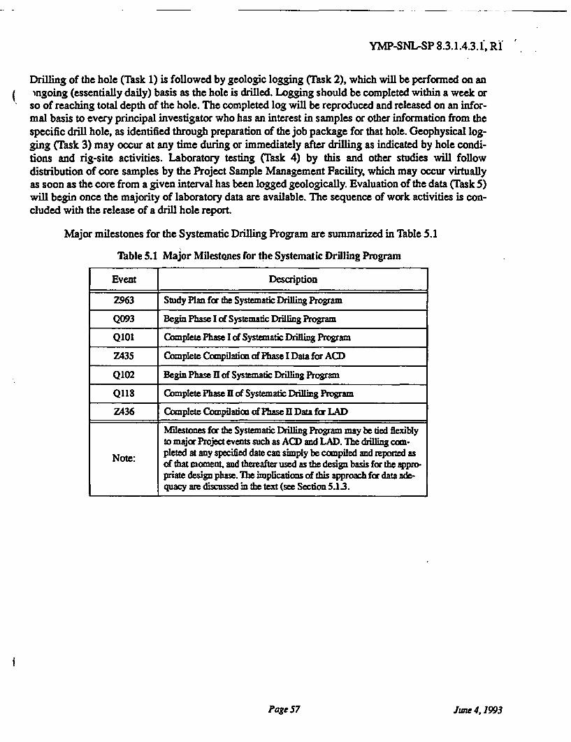
YMP-SNL-SP 8.3.1.4.3.1, R1
Drilling of the hole (Task 1) is followed by geologic logging (Task 2), which will be performed on anongoing (essentially daily) basis as the hole is drilled. Logging should be completed within a week orso of reaching total depth of the hole. The completed log will be reproduced and released on an infor-mal basis to every principal investigator who has an interest in samples or other information from thespecific drill hole, as identified through preparation of the job package for that hole. Geophysical log-ging (Task 3) may occur at any time during or immediately after drilling as indicated by hole condi-tions and rig-site activities. Laboratory testing (Task 4) by this and other studies will followdistribution of core samples by the Project Sample Management Facility, which may occur virtuallyas soon as the core from a given interval has been logged geologically. Evaluation of the data (Task 5)will begin once the majority of laboratory data are available. The sequence of work activities is con-cluded with the release of a drill hole report.
Major milestones for the Systematic Drilling Program are summarized in Table 5.1
Table 5.1 Major Milestones for the Systematic Drilling Program
Event Description
Z963 Study Plan for the Systematic Drilling Program
Q093 Begin Phase I of Systematic Drilling Program
Q101 Complete Phase I of Systematic Drilling Program
Z435 Complete Compilazion of Phase I Data for ACD
Q102 Begin Phase II of Systematic Drilling Program
Q118 Complete Phase II of Systematic Drilling Program
Z436 Complete Compilation of Phase II Data for LAD
Milestones for the Systematic Drilling Program may be tied flexiblyto major Project events such as ACD and LAD. The drilling com-
Note: pleted at any specified date can simply be compiled and reported asof that moment, and thereafter used as the design basis for the appro-priate design phase. The implications of this approach for data ade-quacy are discussed in the text (see Section 5.13.
Page 57 June 4,1993
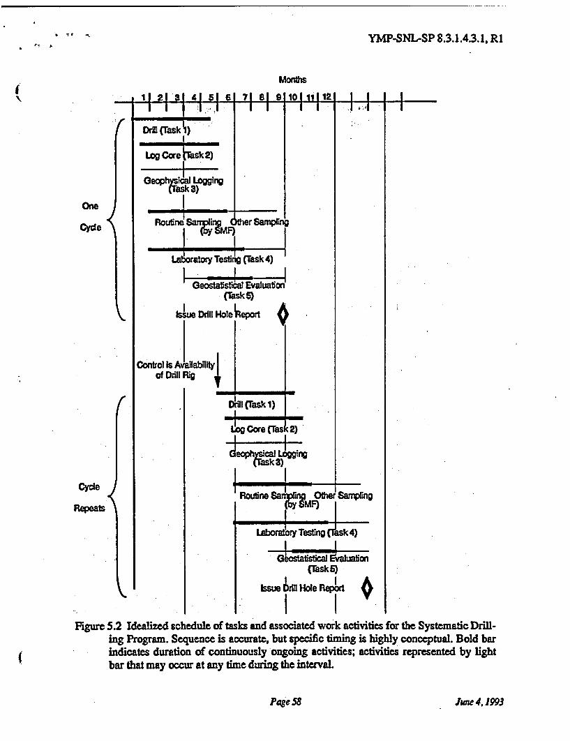
YMP-SNL-SP 8.3.1.4.3.1, R1
Figure 5.2 Idealized schedule of tasks and associated work activities for the Systematic Drill-ing Program. Sequence is accurate, but specific timing is highly conceptual. Bold barindicates duration of continuously ongoing activities; activities represented by lightbar that may occur at any time during the interval.
Page 58 June 4,1993
YMP-SNL-SP 8.3.1.4.3. 1, R1
6.0 REFERENCES
Barnard, R. W, M. L Wilson, H. A. Dockery, J. H. Gauthier, P. G. Kaplan, R. R. Eaton, F. W.Bingham, and T. H. Robey, 1992, TSPA 1991: An initial total-system performance assess-ment for Yucca Mountain: Sandia Report SAND91-2795, Sandia National Laboratories,Albuquerque, NM, in review.
Barnes, R. J., 1988, Bounding the required sample size for geologic site characterization: Mathe-matical Geology, v. 20, p. 477-490.
Borgman, L. E., 1988, New advances in methodology for statistical tests useful in geostatisticalstudies: Mathematical Geology, v. 20, p. 383-403.
Bush, D., and R. E. Jenkins, 1970, Proper hydration of clays for rock property determination:Journal of Petroleum Technology, p. 800-804.
Carr, W. J., 1988, Volcano-tectonic setting of Yucca Mountain and Crater Flat, southwesternNevada: U. S. Geol. Surv. Bull. 1790, p. 35-49.
Clark, I., 1979, Practical geostatistics, New York: Elsevier Applied Science Publishers, 129 p.
Deere, D. U., A. J. Hendron, Jr., F. D. Patton, and E. J. Cording, 1967, Design of surface and near-surface construction in rock, in Failure and Breakage of Rock, Proceedings of the 8thsymposium on rock mechanics, University of Minnesota, September 15-17th, 1966, NewYork: American Institute of Mining Metallurgical and Petroleum Engineers, Inc., p. 237-302.
Deutsch, C., 1989, DECLUS: A Fortran 77 program for determining optimum spatial declusteringweights: Computers & Geosciences, v. 15, p. 325-332.
DOE (U. S. Department of Energy), 1988a, Site characterization plan, Yucca Mountain site,Nevada Research and Development Area, Nevada: U. S. Department of Energy, Office ofCivilian Radioactive Waste Management, Report DOE/RW-0199.
DOE, 1988b, Yucca Mountain Project surface-based investigations plan: U. S. Department ofEnergy, Yucca Mountain Project Office, Report YMP/88-25.
Farmer, I., 1983, Engineering behaviour of rocks, 2nd ed., New York: Chapman and Hall, p. 28.
Isaaks, E. H., and R. M. Srivastava, 1989, An introduction to applied geostatistics, New York.Oxford University Press, 561 p.
Istok, J. D., A. L. Flint, and L. E. Flint, 1991, Spatial variability in rock matrix properties fromsurface outcrop sampling: Agronomy Abstracts, 1991 Annual Meetings, Am. Soc. Agron-omy, Crop Sci. Soc. Am., Soil Sci Soc. Am., p. 222.
Journel A. G., 1983, Nonparametric estimation of spatial distributions: Mathematical Geology, v.15, p. 445-468.
Page 59 June 4,1993
YMP-SNL-SP 8.3.1.4.3.1, R1
Journel, A. G., 1989, Fundamentals of geostatistics in five lessons, Washington DC: Am. Geoph.Union, Short course in geology, v. 8, 40 p.
Journel, A. G., and F. Alabert, 1989, Non-gaussian data expansion in the earth sciences: TerraNova, v. 1, p. 123-134.
Journel, A. G., and C. J. Huijbregts, 1978, Mining geostatistics, New York: Academic Press,6 0 0 p.
Kaplan, P. G., 1991, A formalism to generate probability distributions for performance assess-ment modeling, in High Level Radioactive Waste Management: Proceedings of the Sec-ond Annual International Conference, American Nuclear Society, LaGrange Park, Illinois,p. 1487-1490.
Martin, J. W., C. W. Felice, R. T. DeVan, and B. Ristvet, 1991, The effects of zeolitized tuff on-grain density determinations, in Rock Mechanics as a Multidisciplinary Science, Proceed-ings of the 32nd U. S. Symposium, J.-C. Roegiers, ed., Rotterdam: A. A. Balkema Pub-lishers, p. 325-334.
McBratney, A. B., and R. Webster, 1983, How many observations are needed for regional estima-tion of soil properties?: Soil Science, v. 135, p. 177-183.
Mood, A. M., P. A. Graybill, and D. C. Boes, 1974, Introduction to the theory of statistics, 3rd ed.,New York, McGraw-Hill Book Co., p. 251-265.
Ortiz, T. S., R. L. Williams, F. B. Nimick, B. C. Whittet, and D. L. South, 1985, A three-dimen-sional model of reference thermal-mechanical and hydrological stratigraphy at YuccaMountain, southern Nevada: Sandia Report SAND84-1076, Sandia National Laboratories,Albuquerque, New Mexico, 71 p.
Rasmussen, T. C., D. D. Evans, P. J. Sheets, and J. H. Blanford, 1989, Unsaturated fractured rockcharacterization methods and data sets at the Apache Leap Tuff site: Final Report to the U.S. Nuclear Regulatory Commission, Division of Engineering, Office of Nuclear Regula-tory Research, Washington, DC, under Contract No. NRC-04-86-114, April 1, 1989.
Rautman, C. A., 1991, Estimates of spatial correlation in volcanic tuff, Yucca Mountain, Nevada:Sandia Report 89-2270, Sandia National Laboratories, Albuquerque, New Mexico, 117 p.
Rautman, C. A., and A. H. Treadway, 1991, Geologic uncertainty in a regulatory environment: anexample from the Potential Yucca Mountain nuclear waste repository site: EnvironmentalGeology and Water Science, v. 18, p. 171-184.
Rautman, C. A., and A. L. Fint, 1992, Deterministic geologic processes and stochastic modeling:Proceedings of the 3rd International High-Level Radioactive Waste Management Confer-ence, April 13-17, 1992, Las Vegas, Nevada, American Nuclear Society, LaGrange Park,Illinois, p. 1617-1624.
Soeder, D. J., L. E. Flint, and A. L. Flint, 1991, Effects of sample handling and measurement
Page 60 June 4,1993
YMP-SNL-SP 8.3.1.4.3.1, R1
methodology on the determination of porosity in Volcanic rock samples: AgronomyAbstracts, 1991 Annual Meetings, Am. Soc. Agronomy, Crop Sci. Soc. Am., Soil Sci.Soc. Am., p. 232.
Spengler, R. W., F. M. Byers, Jr., and J. B. Warren, 1981, Stratigraphy and structure of volcanicrocks in drill hole USW-G1, Yucca Mountain, Nye County, Nevada, U. S. Geol. SurveyOpen-File Report 81-1349, 50 p.
Spengler, R. W. and M. P. Chornack, 1984, Stratigraphic and structural characteristics of volcanicrocks in core hole USW G-4, Yucca Mountain, Nye County, Nevada: U. S. Geol. SurveyOpen-File Report 84-789, 77 p., with a section on Geophysical Logs by D. C. Muller andJ. E. Kibler.
Yfantis, E. A., G. T. Flatman, and J. V. Behar, 1987, Efficiency of kriging estimation for square,triangular, and hexagonal grids: Mathematical Geology, v. 19, p. 183-205.
Younker, J. L, and others, 1992, Report of early site suitability evaluation of the potential reposi-tory site at Yucca Mountain, Nevada: Report SAIC-91-8000, Science Applications Inter-national Corp., Las Vegas, Nevada
Page 61 June 4,1993
SP 8.3.1.4.3.1, R 1
The following is for Office of Civilian Radiaoctive Waste Management Records Managementpurposes only and should not be used when ordering this document:
Accession number: NNA.9306070214
Sandia National LaboratoriesAlbuquerque, New Mexico 87185
JUN - l 1993WBS: 1.2.9QA: NA
Carl P. Gertz, Project ManagerYucca Mountain Site Characterization
Project OfficeU. S. Department of EnergyNevada Operations Office101 Convention Center DrivePhase 2, Suite 200Las Vegas, Nevada 89193-8518
Attention: V. F. Iorii
Subject: April, 1993 Monthly Highlights and Status Report
Dear Carl:
Enclosed is the Monthly Highlights and Status Report for themonth of April, 1993. If you have any questions, please callLeigh Lechel at FTS 844-4824.
Sincerely,
L. E. ShephardTechnical Project OfficerYMP Project ManagementDept. 6302
LL:6352:peEnclosure
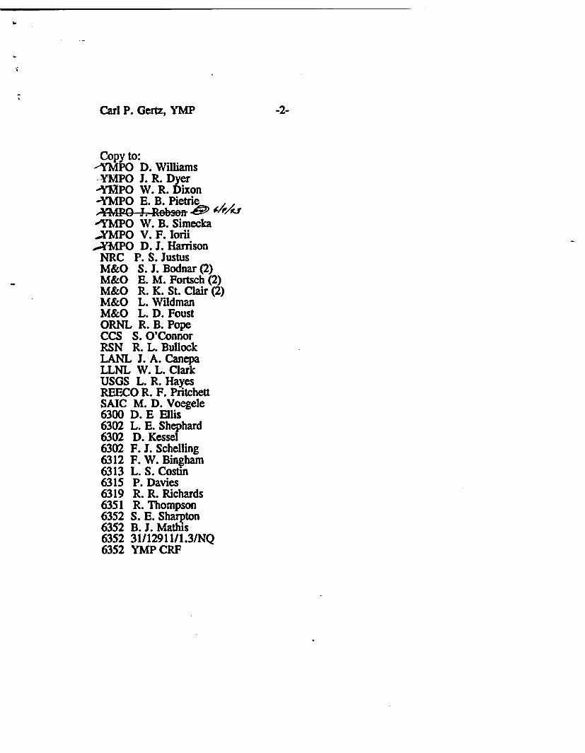
Carl P. Gertz, YMP -2-
Copy to:YMPO D. WilliamsYMPO J. R. DyerYMPO W. R. DixonYMPO E. B. Pietrie
YMPO W. B. SimeckaYMPO V. F. Iorii
YMPO D. J. HarrisonNRC P. S. JustusM&O S. J. Bodnar (2)M&O E. M. Fortsch (2)M&O R. K. St. Clair (2)M&O L. WildmanM&O L. D. FoustORNL R. B. PopeCCS S. O'ConnorRSN R. L. BullockLANL J. A. CanepaLLNL W. L. ClarkUSGS L. R. HayesREECO R. F. PritchettSAIC M. D. Voegele6300 D. E Ellis6302 L. E. Shephard6302 D. Kessel6302 F. J. Schelling6312 F. W. Bingham6313 L. S. Costin6315 P. Davies6319 R. R. Richards6351 R. Thompson6352 S. E. Sharpton6352 B. J. Mathis6352 31/12911/1.3/NQ6352 YMP CRF
May 1993
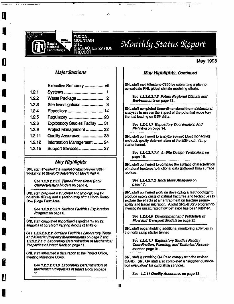
May 1993
Major Sections May Highlights, Continued
Executive Summary ................ vii12.1 Systems ................. 11.22 Waste Package ...................... 21.2.3 Site Investigations ................. 312.4 Repository ................. 14
12.5 Regulatory ................. 2012.6 Exoratory Studies Facility ..... 31
1.2.9 Project Management ............... 3212.11 Quality Assurance ................. 331.2.12 Information Management ........ 3412.15 Support Services .37
May HighlightsSNL staff attended the annual contract-review SCRFworkshop at Stanford University on May 3 and 4.
See 1.2.3.2.2.2.2 Three-DimensionalRockCharacterstics Models on page 4.
SNL staff prepared a structural and lithologic log forborehole NRG-2 and a section map of the North RampBow Ridge Fault Area.
See 1.2.3.2.6.2.1 Surface Facilities ExplorationProgram on page 6.
SNL staff completed unconfined experiments on 22samples of core from varying depths of NRG-6.
See 1.2.3.2.6.2.2 Surface Facilities Laboratory Testsand Material Property Measurements on page 7 and1.1.3.2.7.1.3 Laboratory Determinaton of MechanicalProperties of Intact Rock on page 11.
SNL staff submitted a data report to the Project Office,meeting Milestone OS46.
See 1.2.3.2.7.1.3 Laboratory Determnation ofMechanical Properties of Intact Rock on page11.
SNL staff met Milestone OS50 by submitting a plan toconsolidate PNL global climate modeling efforts.
See 1.2.3.6.2.1.6 Future Regional Climate andEnvironments on page 13.
SNL staff completed three-dimensional thermal/structuralanalyses to assess the impact of the potential repositorythermal loading on ESF drifts.
See 1.4. 1.1 Repository Coordination andPlanning on page 14.
SNL staff continued to analyze seismic blast monitoringand rock quality determination at the ESF north rampstarter tunnel.
See 1.2.4.2.1.1.4 In Situ Design Verification onpage 16.
SNL staff continued to compare the surface characteristicsof natural fractures to frictional data gathered from surfacereplicas.
See 1.2.4.2.1.2 Rock Mass Analyses onpage 17.
SNL staff continued work on developing a methodology toproduce epoxy casts of natural fractures and techniques toexplore the effects of air entrapment on fracture perme-abirty and tracer migration. A joint SNL-USGS program toinvestigate unsaturated flow behavior has been initiated.
See 1.2.5.4.6 Development and Validation ofFlow and Transport Models on page 26.
SNL staff began fielding additional monitoring activities inthe north ramp starter tunnel.
See 1.2.6.1.1 Explortory Studies FacilityCoordination, Planning, and TechnicalAssess-menton page 31.
SNL staff is rewriting QAIPs to comply with the revisedQARD. SNL QA staff also completed a "supplier qualifica-
tion evaluation" for calibration services.
See 1.2.1.1 Quality Assurance on page 33.
iii

MAY 1993
DISCLAIMER
Quality assurance checks on data contained in this report have been performed onlythat the data have been obtained and documented properly. The SNL Projeccautions that any information is preliminary and subject to change as furtherperformed or as an enlarged and perhaps more representative data base is accumdata and interpretations should be used accordingly. Milestones have not been basincluded only to show status.
y to determinet Departmentanalyses are
ulated. Theseelined and are
iv
MAY 1993
TABLE OF CONTENTS
WBS 1.2.1
WBS 1.2.1.1WBS 1.2.1.2.1WBS 1.2.1.2.2
WBS 1.2.1.5
WBS 1.2.2
WBS 1.2.2.4.3
WBS 1.2.3
WBS 1.2.3.1WBS 1.2.3.2.2.2.1WBS 1.2.3.2.2.2.2WBS 1.2.3.2.6.2.1WBS 1.2.3.2.6.2.2
WBS 1.2.3.2.6.2.3WBS 1.2.3.2.7.1.1WBS 1.2.3.2.7.1.2WBS 1.2.3.2.7.1.3WBS 1.2.3.2.7.1.4WBS 1.2.3.2.8.3.3
WBS 1.2.3.6.2.1.6
WBS 1.2.4
Systems Engineering ...............................
Systems Engineering Coordination and Planning (Schelling) ............... 1Program-Level Requirements Document Development (Schelling) .... ....... 1Project-Level Requirements Documents Development andMaintenance (Schelling) ....................................... 1Special Studies (Schelling) ....... ..................... . 1
Waste Package .. 2
Container/Waste Package Interface Analysis (Ryder) ................... . 2
Site Investigations ...... . . ........ . . . . ... . . 3
Site Investigations Coordination and Planning (Rautman) ................. 3Systematic Acquisition of Site-Specific Subsurface Information (Rautman) ..... 3Three-Dimensional Rock Characteristics Models (Rautman) ............... 4Surface Facilities Exploration Program (Shephard) ...................... 6Surface Facilities Laboratory Tests and Material PropertyMeasurements (Shephard) ..................................... 7Surface Facilities Field Tests and Characterization Measurements (Shephard) ... 8Laboratory Thermal Properties (Chocas) ............................ 8Laboratory Thermal Expansion Testing (Chocas) ....................... 10Laboratory Determination of Mechanical Properties of Intact Rock (Price) .... .. 11Laboratory Determination of the Mechanical Properties of Fractures (Price) ..... 12Ground Motion From Regional Earthquakes and Underground NuclearExplosions (Shephard) ........................................ 13Future Regional Climate and Environments (Schelling) ................... 13
Repository ............ .. .. ... .... . ... ........... . 14
Repository Coordination and Planning (Costin) ........................ 14Excavation Investigations (Pott) .................................. 15In Situ Thermomechanical Properties (Pott) .......................... 15In Situ Mechanical Properties (Pott) ............................... 16In Situ Design Verification (Pott) ................................. 16Rock Mass Analyses (Jung) ...................................... 17Certification of Design Methods (Jung) ............................. 18Design Analysis (Ryder) ....................................... 19Sealing and Design Requirements (Fernandez) ........................ 19
Regulatory . . . .. ... ....... ............ . 20
Regulatory Coordination and Planning (Dockery) ....................... 20Site Characterization Program (Schelling) ............................ 20Technical Database Input (Eley) .................................. 21Total System Performance Assessment (Dockery) ...................... 21Repository Performance Assessment (Ryder) ......................... 23Site Performance Assessment (Dockery) ............................ 24
WBSWBSWBSWBSWBSWBSWBSWBSWBS
1.2.4.1.11.2.4.2.1.1.11.2.4.2.1.1.21.2.4.2.1.1.31.2.4.2.1.1.41.2.4.2.1.21.2.4.2.3.11.2.4.2.3.21.2.4.6.1
WBS 1.2.5
WBSWBSWBSWBSWBSWBS
1.2.5.11.2.5.2.21.2.5.3.51.2.5.4.11.2.5.4.31.2.5.4.4
v
MAY 1993
TABLE OF CONTENTS(continued)
WBSWBSWBSWBSWBS
1.2.5.4.51.2.5.4.61.2.5.4.71.2.5.4.91.2.5.5
Interactive Graphics Information System (Jones) ......................Development and Validation of Flow and Transport Models (Tidwell) .........Supporting Calculations for Postclosure Performance Analyses (Sobolik) ......Development and Verification of Flow and Transport Codes (Dockery) ........Special Projects (Dockery) ......................................
2526293030
WBS 1.2.6 Exploratory Studies Facility ................... 31
WBS 1.2.6.1.1 Exploratory Studies Facility Coordination, Planning, and TechnicalAssessment (Pott) ................................. .......... 31
WBS 1.2.9
WBS 1.2.9.1.2WBS 1.2.9.2.2
Project Management ............................... 32
Technical Project Office Management (Schelling) ...................... 32Project Control (Hotchkiss) .......... ........................... 32 I
WBS 1.2.1 1 Quality Assurance (Richards) ......... 33... . . ........ . . .
WBS 1.2.12
WBSWBSWBSWBS
1.2.12.11.2.12.2.21.2.12.2.31.2.12.2.5
Information Management .. 34
Information Management Coordination and Planning (Hotchkiss) ..... ....... 34Local Records Center Operation (Sharpton) ......... .. ............... 34Participant Records Management (Sharpton) ......... .. .............. 35Document Control (Sharpton) .................................... 36
Support Services . ... . . . . . 37
Support Services Coordination and Planning (Hotchkiss) ................ 37Administrative Support (Hotchkiss) ................................. 37YMP Support for the Training Mission (Sharpton) .. 38
WBS 1.2. 15
IWBSWBSWBS
1.2.15.11.2.15.21.2.16.3
vi
MAY 1993
YUCCA MOUNTAIN SITE CHARACTERIZATION PROJECTEXECUTIVE SUMMARY
WBS 1.2.3.2.2.2 Three-Dimensional Rock Characteristics Models
SNL staff attended the annual contract-review Stanford Center Reservoir Forecasting (SCRF) workshopat Stanford University on May 3 and 4. Recent developments in geostatistics and their applications werepresented by Stanford graduate students and by industrial affiliates. Although the scope of research atSCRF is quite broad and many of the results are somewhat preliminary. there are some very directapplications to the YMP. The reproduction of multiple-point connectivity statistics in simulated modelshas particular application at Yucca Mountain, because the closest anticipated drillhole spacings (condi-tioning data) are probably dose to or slightly greater than the expected range of correlation (based uponsurface transect sampling). The sparse nature of conditioning data relative to the correlation length canproduce stochastic lithologies in conceptually and physically anomalous positions. Use of higher-orderstatistics should alleviate this problem.
WBS 1.2.3.2.6.2.1 Surface Facilities Exploration Program
A structural and lithologic log was prepared for borehole NRG-2. A section map of the North Ramp BowRidge Fault area was prepared to Incorporate the most recent information from boreholes NRG-2 andNRG-2A.
WBS 1.2.3.2.6.2.2 Surface Facilities Laboratory Tests and Material Property Measurements
* Mechanical properties experiments (WBS 1.2.3.2.7.1.3) data for core from NRG-6 at varying depthswere collected and submitted to the YMP Central Records Facility.
WBS 1.2.3.2.7.1.3 Laboratory Determination of Mechanical Properties of Intact Rock
* SAND92-1810, "Unconfined Compression Experiments on Topopah Spring Member Tuff at 220C and aStrain Rate of 10 s : Data Report," was sent to the Project Ofice on May 13,1993 (Milestone OS46).
* The first series of unconfined experiments were completed on 22 samples (collected at varying depths)of core from NRG-6. These data have been transmitted to the Exploratory Studies Facility (ESF) designteam.
WBS 1.2.3.6.2.1.6 Future Regional Climate and Environments
* The transition plan for consolidating Pacific Northwest Laboratory (PNL) efforts on global climatemodeling into a single SNL effort was transmitted to the Project Office for review (Milestone OS50).
WBS 1.2.4.1.1 Repository Coordination and Planning
* Work continued on a series of analyses, In support of the design of the ESF north ramp. Three-dimen-sional thermal/structural analyses of the repository to assess the impact of the potential repositorythermal loading on the ESF drifts have been completed. Results of these analyses will support two-dimension analyses of several cross sections of the ESF north ramp to evaluate long-term stability.Geotechnical data from the NRG holes will be incorporated into the analyses. The analyses areexpected to provide input for the 90% design review.
vii
MAY 1993
YUCCA MOUNTAIN SITE CHARACTERIZATION PROJECTEXECUTIVE SUMMARY Continued
WBS 1.2.4.2.1.1.4 In Situ Design Verification
* At the ESF north ramp starter tunnel, staff continued analyses on seismic blast monitoring, rock qualitydetermination, and convergence monitoring.
WBS 1.2.4.2.1.2 Rock Mass Analyses
* A study comparing the surface characteristics of natural fractures to the frictional data gathered onreplicas of the surfaces Is continuing. This study will place special emphasis on determining whether thefitting parameters on the Barton model for frictional behavior have physical significance.
WBS 1.2.5.4.6 Development and Validation of Flow and Transport Models
* Development of a methodology to produce epoxy casts of natural fractures continued. Most work wasconcentrated on control of the boundary conditions. A test fracture prepared in April using externalmanifolds to control inflow and boundary conditions was subjected to preliminary tests.
* Development of experimental techniques to explore the effects of air entrapment on fracture permeabil-ity and tracer migration continued. Hardware to allow acquisition of both high- and low-resolutionimages of the test fracture at controlled intervals during the experiment was acquired and installedduring May.
* A joint laboratory program with staff at USGS has been initiated for investigating unsaturated flowbehavior in fractured volcanic tuff.
WBS 1.2.5.4.1 Total System Performance Assessment
* SNL staff coordinated and hosted a meeting with other participants to discuss the best approach forrepresenting infiltration and water flow at Yucca Mountain resulting from both current and future climaticconditions. The results from the discussion will be used as the basis for the percolation flux used in thesecond cycle of the Total System Performance Assessment (TSPA-2).
WBS 1.2.6.1.1 ESF Coordination, Planning, and Technical Assessment
* SNL staff began fielding additional monitoring activities In the north ramp starter tunnel to address safetyconcerns. Convergence monitoring of the tunnel was conducted and rock bolt load cells for evaluatingground support were installed.
WBS 1.2.1.1 Quality Assurance
* QA staff continued revising Quality Assurance Implementing Procedures (QAIPs) to update the criteriain keeping with the revised Quality Assurance Requirements Document.
* SNL YMP QA staff completed a "supplier qualification evaluation" of the portion of the SNL SecondaryStandards Laboratories that provides calibration services for electrical/electronics, temperature, pres-sure, load cell, and acceleration measuring and test equipment. The facilities and personnel were foundto be capable of providing such services, so are considered qualified."
viii
MAY 1993
1.2.1 SYSTEMS ENGINEERING
The objective of the Systems Engineering element is to apply the systems engineering discipline to transformthe regulatory requirements into functional needs to the MGDS design, system configuration, and sitecharacterization activities. The Systems Engineering element is comprised of four tasks: Systems EngineeringCoordination and Planning (1.2.1.1), Program-Level Requirements Document Development (1.2.1.2.1), Project-Level Requirements Documents Development and Maintenance (1.2.1.2.2), and Special Studies (1.2.1.5), whichincludes development of items important to safety/waste isolation.
1.2. 1.1 SYSTEMS ENGINEERINGCOORDINATION AND PLANNING
7.2.1.2.1 PROGRAM-LEVEL REQUIREMENTSDOCUMENT DEVELOPMENT
1.2.1.2.2 PROJECT-LEVEL REQUIRMENTSDOCUMENTS DEVELOPMENT ANDMAINTENANCE
1.2.1.5 SPECIAL STUDIES
Major Accomolishments
SAND92-2334, Preclosure Radiological SafetyEvaluation: Exploratory Studies Facility," by F. J.Schelling and J. D. Smith, received Projectapproval for publication.
Status Report on Ongoing Activities
Status Report on Ongoing Activities
Several Project requirements documents, includingthe Exploratory Studies Facility Design Require-ments Document (ESFDRD), the Surface-BasedTest Facility Requirements Document (SBTFRD),and the Engineered Barrier Design RequirementsDocument (EBDRD), were received for anotherround of comment review. Because of the lack offunding in WBS element 1.2.1.2.2, this work ischarged to WBS element 1.2.9.1.2.
Staff continued to participate on several teams ofthe Site Characterization Plan (SCP) ThermalGoals Working Group and provided draft input forthe Thermal-Mechanical Team and the Opera-tions, Safety, and Environment Team on May 25.Because of the lack of funding in WBS element1.2.1.5, this work is charged to WBS element1.2.5.4.3.
1
MAY 1993
1.2.2 WASTE PACKAGE
The objective of the Waste Package element includes support to the Container/Waste Package InterfaceAnalysis element (1.2.2.4.3) in the conduct of thermal and structural analysis of the near-field environment thatwill support evaluations of emplacement orientation, the effects of backfill properties and timing, as well asother thermal loading issues related to waste package design.
1.2.2.4.3 CONTAINER/WASTE PACKAGEINTERFACE ANALYSIS
No significant activity this reporting period.
2
MAY 1993
1.2.3 SITE INVESTIGATIONS
The objective of the Site Investigations element includes work scope related to site data collection and analysisto support site suitability evaluation, design, licensing, performance assessment requirements, and the naturalbarrier system component of the multiple barrier system described in the physical system. The SiteInvestigations element is comprised of twelve tasks: Site Investigations Coordination and Planning (1.2.3.1),Systematic Acquisition of Site-Specific Subsurface Information (1.2.3.2.2.2.1), Three-Dimensional RockCharacteristics Models (1.2.3.2.2.2.2),SurfaceFacilities ExplorationProgram (1.2.3.2.6.2.1), SurfaceFacilitiesLaboratory Tests and Material Property Measurements (1.2.3.2.6.2.2), Surface Facilities Field Tests andCharacterization Measurements (1.2.3.2.6.2.3), Laboratory Thermal Properties (1.2.3.2.7.1.1), LaboratoryThermal Expansion Testing (1.2.3.2.7.1.2), Laboratory Determination of Mechanical Properties of Intack Rock(1.2.3.2.7.1.3), Laboratory Determination of the Mechanical Properties of Fractures (1.2.3.2.7.1.4), GroundMotion From Regional Earthquakes and Underground Nuclear Explosions (1.2.3.2.8.3.3), and the FutureRegional Climate and Environments (1.2.3.6.2.1.6).
1.2.3.1 SITE INVESTIGATIONS COORDINATIONAND PLANNING
1.2.2.2.2.2.1 SYSTEMATIC ACQUISITION OFSITE-SPECIFIC SUBSURFACEINFORMATION
Status Report on Ongoing ActivitiesStatus Report on Ongoing Activities
SNL staff were unable to attend the May 5Sample Overview Committee (SOC) meetingbecause of illness and schedule conflicts foralternate representatives. The next SOC meetingis scheduled for June 2.
The FY94 Draft Site Characterization Annual Planwas reviewed in detail. Activity descriptionswere updated, priorities were renewed, and FY94deliverables were updated. Meetings were heldwith Project Office personnel to discuss proposedchanges.
The paper entitled "Spatial Variability ofHydrologic Properties in Volcanic Tuff," intendedfor publication in the journal Groundwater, hasentered U.S. Geological Survey (USGS) andSandia National Laboratories (SNL) review. Thepaper, an expansion of work originally presentedat the International High-Level Radioactive WasteManagement Conference in April, includes a testof the hypotheses developed by the original work.(SCP Activities 8.3.1.4.3.1.1 and 8.3.1.2.2.3.1)
The FY94 budget process began during May.SNL staff spent a significant amount of timerewriting prior-year descriptions of expected FY94work to reflect the accelerated drilling programresulting from the combination of hole SD-1 1 withSRG-5. An increased focus on identifying inter-activity and interparticipant links required extratime, but will result in a more closely integratedprogram. (SCP Activity 8.3.1.4.3.1.1)
SNL staff normally assigned to this activitycontinued to provide geologic support for WBSelement 1.2.3.2.6.2 (SCP Activity 8.3.1.14.2.1).Geologic logging of core is the principal focus ofthis support. The logging, which is being doneunder the scientific notebook procedure in use forthe Soil and Rock Properties Study, has providedan opportunity to refine the technical procedure
3
MAY 1993
that will guide work on the Systematic DrillingProgram. Comparison of log results with theequivalent rock units now exposed in the portalexcavations for the north ramp suggest someinteresting interpretations of the "poorcore recovery" observed in hole NRG-1 andelsewhere. This "poor" core recovery mayactually result from the presence of large (>1 ft)lithophysal cavities prominently displayed in thenew excavations. The implications of thisobservation and the nonconventional interpreta-tions will be explored as additional data aregathered. (SCP Activity 8.3.1.4.3.1.1)
The draft data reports, tentatively entitled"Physical and Hydrologic Properties of OutcropSamples from a Nonwelded to Welded TuffTransition, Yucca Mountain, Nevada' and"Physical and Hydrologic Properties of SurfaceOutcrop Samples at Yucca Mountain, Nevada,"that contain the laboratory results of the outcropsampling studies conducted at Yucca Mountainover the past several years under this activity,remain largely in deferred status pendingcompletion of 105 C oven-drying and measure-ment of hard-dried material properties. Coauthorcomments were incorporated into the text. (SCPActivities 8.3.1.4.3.1.1 and 8.3.1.2.2.3.1)
Maior Activities Uncoming Next Three Months
1.2.3.2.2.2.2 THREE-DIMENSIONAL ROCKCHARACTERISTICS MODELS
Maior Accomplishments
Report 6, summarizing the results of researchconducted during 1992, has been received fromthe Stanford Center for Reservoir Forecasting(SCRF). This is the major annual deliverable forthe SCRF contract. (SCP Activity 8.3.1.4.3.2.1)
Significant Meetings Attended
Drafts of reports in preparation will be finalizedand reviewed as appropriate. Beyond this wind-down of existing scoping activities, principalemphasis will be placed on completing allprocedures and other prerequisites for initiatingthe Systematic Drilling Program with hole SD-11 /SRG-5 in July. SNL staff are preparing inputin anticipation of a mid-June workscopeconsolidation meeting for a second SD hole,presumably SD- 2, to be located near the maintest level drifts of the ESF between the north andsouth ramps. (SCP Activity 8.3.1.4.3.1.1)
Budget preparation for FY94 will continue. (SCPActivity 8.3.1.4.3.1.1)
Geologic support will continue to be provided tothe Soil and Rock Properties Study (SCP Activity8.3.1.14.2.1) through logging core from the northramp boreholes. Technical procedures to supportthe Systematic Drilling Program will be finalizedas quickly as possible. (SCP Activity8.3.1.4.3.1.1)
SNL staff attended the annual contract-reviewSCRF workshop at Stanford University on May 3and 4. Recent developments in geostatistics andits applications were presented by Stanfordgraduate students and by industrial affiliates.(SNL is an industrial affiliate.) Several papers ofsignificance addressed (1) major work on the jointsimulation of multiple spatially correlated variablesusing a Markov-Bayes (M-B)-type model ofcoregionalization; (2) revisions to the sequentialsimulation algorithm to enhance reproduction ofspatial continuity patterns; (3) a merging of fractaltechniques with classic geostatistical methods;(4) an expansion of earlier work on simulatingmultiple-point statistics (most geostatisticalmethods are based on two-point continuitymeasures); and (5) efforts to speed simulation ofvery large models through probability-fieldtechniques.
Although the scope of research at SCRF is quitebroad and many of the results are somewhatpreliminary, there are some very direct appli-cations to the Yucca Mountain Site Characteri-zation Project (YMP). The M-B approach tomultiple variables is probably the most significant,because groundwater flow is inherently a multi-variate problem. The material property fields usedas input to flow computations must reflectproperly the joint variability and continuitypatterns. Simulating these fields separately in alllikelihood distorts the cross-variable correlationpatterns extant in nature, and these M-B tech-niques may permit more reasonable simulationswithout the complexity and numerical problemsadded by a full coregionalization model. Thetechnique has been applied to reservoir charac-terization of porosity and permeability in the NorthSea with apparent success. The reproduction ofmultiple-point connectivity statistics in simulated
4
MAY 1993
models also has particular application at YuccaMountain, because the closest anticipateddrillhole spacings (conditioning data) are probablyclose to or slightly greater than the expectedrange of correlation (based upon surface transectsampling). The sparse nature of conditioning datarelative to the correlation length can producestochastic lithologies in conceptually andphysically anomalous positions. Use of higher-order statistics should alleviate this problem.
The SCRF report will be evaluated for relevanceto the YMP, and aspects will be incorporated intoYMP modeling work as appropriate. Althoughmost, if not all, of this work will eventually findits way into the open literature, SCRF affiliatesreceive the information, algorithms, and softwaretwo to three years prior to regular publication.(SCP Activity 8.3.1.4.3.2.1)
SNL staff also met with representatives ofDynamic Graphics, Inc., in Alameda, CA. TheProject has been exploring converting the three-dimensional modeling work being conducted byboth the USGS (geometric) and SNL (materialproperties) to the Dynamic Graphics system fromthe Lynx GMS system currently in use by bothtechnical participants. Although the newDynamic Graphics system is much improved overprevious releases of similar software formodeling complex geometries, the package stillappears less suited to the unique, data-sparse/interpretation-heavy needs of the YMP. Also, thematerial-properties modeling capabilities of theDynamic Graphics package are not yet imple-mented. One of the major attractions of the Lynxsoftware package was the close integration ofgeometric modeling (rock units, faults) with thegeostatistical routines necessary for variogramanalysis and driving. Lynx also features ongoingefforts to incorporate simulation algorithms in aparallel manner. Staff will continue to monitordevelopment of both systems, and to encourageLynx Geosystems to improve their display andpost-modeling manipulation capabilities, a featureat which Dynamic Graphics excels. (SCP Activity8.3.1.4.3.1.1)
Status Report on Ongoing Activities
(DOE/NRC) level-of-detail agreement for studyplans. Because the Three-Dimensional RockCharacteristics Models Study will create custommodels upon demand to support performanceassessment and design evaluation activities, thestudy plan will be a listing and brief description ofa number of tools that can be used as needed tocreate the physical property distributions neededfor a particular calculation. (SCP Activity8.3.1.4.3.2.1)
Preparation of the FY94 Planning and ControlSystem (PACS) budget began during May.Software development and modeling activities willbe much more focused and more closely tied tothe using groups and activities. In general,emphasis will be placed on meeting specific ESF-related assessments, while not neglecting thelonger-term development of integrated modelingtechniques required for license applicationevaluations. (SCP Activity 8.3.1.4.3.2.1)
Maior Activities Upcoming Next Three Months
Work will commence on modifying the simulationcodes to accommodate the soft informationprovided by the microstratigraphic units known atYucca Mountain. SNL and USGS staff willdiscuss the required interfaces to the geometricmodel being developed by the USGS. The initialLynx model of the Topopah Spring Member of thePaintbrush Tuff, including its internal micro-stratigraphic zonation, is scheduled to becompleted by the USGS. A description of thetheory and proposed work is being prepared toclarify the extent of the effort. (SCP Activity8.3.1.4.3.2.1)
Additional support staff, including severalpersonnel with significant geostatistical training,will join the study next month for portions of thesummer. They will develop an underlying designfor integrated software that combines thecurrently separate GSLIB subroutines to automatecreation and evaluation of large simulations. Thiswork is a collaborative development effort withother user groups at SNL, including YMP, theFernald (Ohio) Integrated Demonstrations Project,and Environmental Restoration groups. (SCPActivity 8.3.1.4.3.2.1)
SNL staff will contribute text sections to the1993 Total System Performance Assessment(TSPA) summary document describing the
Preparation of the study plan for the Three-Dimensional Rock Characteristics Models Studycontinues, using the revised U.S. Department ofEnergy/Nuclear Regulatory Commission
5
MAY 1993
construction of the repository-scale three-dimensional indicator simulations of lithology.Preliminary drafts are being revised to incorporatepreliminary comments. The relative role of thesetext sections in the overall TSPA report will beresolved as the TSPA exercise proceeds and afinal outline is prepared. (SCP Activity8.3.1.4.3.2.1)
1.2.3.2.6.2.1 SURFACE FACILTIESEXPLORATION PROGRAM
Major Accomplishments
A structural and lithologic log was prepared forborehole NRG-2. A section map of the NorthRamp Bow Ridge Fault area was prepared toincorporate the most recent information fromboreholes NRG-2 and NRG-2A.
Significant Meetings Attended
The SNL Soil and Rock Properties principalinvestigator and staff met with the ESF DesignTeam, Sample Management Facility (SMF) staffgeologists, and the DOE staff at the SMF on May20 to review the core from NRG-2A and todiscuss further drilling along the north rampalignment in the vicinity of the Bow Ridge Fault.The following conclusions were developed:
1. NRG-2A will be deepened to provide alithologic contact of high confidence.
2. NRG-2 will be deepened to ensure completepenetration of the Bow Ridge Fault and toprovide a lithologic contact of highconfidence to the east of the fault.
3. Another borehole, NRG-2B, will be drilled toprovide additional information for a zone ofno core recovery in the Rainier Mesa inNRG-2. This hole will be drilled and coredthrough the Rainier Mesa into the underlyingTiva Canyon caprock. The hole will notcross the Bow Ridge Fault.
An overview of the soil and rock properties studyand the section map of the North Ramp BowRidge Fault area was presented to members ofthe NRC during the site visit on May 25.
Status Report on Ongoing Activities
Borehole NRG-5 is being deepened to approxi-mately 1300 ft. Structural and lithologic logshave been prepared for boreholes NRG-1, RF-8,and NRG-6. Technical review of the logs is inprogress, and the logs will be issued in mid-June.Structural and lithologic logs are being preparedfor boreholes NRG-3, NRG-2A, and NRG-5.
6
MAY 1993
Major Activities Upcoming Next Three Months
Boreholes NRG-4, NRG-2B, and SRG-5 will bedrilled, and structural and lithologic logs will beprepared.
1.2.3.2.6.2.2 SURFACE FACILTIESLABORATORY TESTS ANDMATERIAL PROPERTYMEASUREMENTS
Major Accomplishments
Mechanical properties data (ultrasonic velocities,static elastic properties, and unconfined strength)for core from NRG-6 from depths of 22.2 ft to328.7 ft were submitted to the YMP CentralRecords Facility (CRF).
Status Report on Ongoing Activities
Mechanical properties testing is underway on coresamples from NRG-6 and NRG-2. Thermalproperties testing is underway on core samplesfrom NRG-6.
Major Activities Upcomina Next Three Months
Core samples from NRG-3, NRG-2A, NRG-4,NRG-2B, and NRG-5 will be submitted formechanical properties testing.
7

MAY 1993
1.2.3.2.6.2.3 SURFACE FACILIES FIELDTESTS AND CHARACTERIZATIONMEASUREMENTS
1.2.3.2.7.1.1 LABORATORY THERMALPROPERTIES
Status Report on Ongoing ActivitiesMajor Accomplishments
Procedures for Schmidt-Hammer tests of corefrom the north and south ramp boreholes wereprepared. Equipment to perform these tests wasprocured.
Status Report on Ongoing Activities
Planning for soil resistivity tests on the northportal pad are underway. Equipment to performthe tests has been procured and calibrated.
Maior Activities Upcoming Next Three Months
The Work Agreement (WA-0079) for the study onthe effects of sample saturation on thermalconductivity was issued, and samples are readyfor testing. These experiments are necessary todetermine whether thermal conductivity has apredictable dependence on the saturation state ofthe sample and, if so, to describe the nature ofthe relationship. Results from these experimentswill be used to determine the optimal baseline testconditions for thermal conductivity characteri-zation. (SCP Activity 8.3.1.15.1.1.3)
A successful calibration of the C-Matic lowtemperature (LT) instrument was completedwithout the moisture containment cell.Calibration runs using moisture containment cellsmade from the polymer DelrinD were found to beunstable. Moisture containment cells made fromKel-F are being fabricated and will be used fortesting samples in a controlled environment. TheLT is used to measure thermal conductivity usingthe guarded-heat-flow-meter method attemperatures below 100 C.
ISoil resistivity tests will be performed at the northportal pad.
An additional LT instrument has been ordered tosupport increased thermal conductivity testingrequirements. This instrument is anticipated to beoperational early in June. Because testing ofsamples to support the ESF/repository design haspriority over the study on saturation effects onthermal conductivity, the study will be delayeduntil sufficient equipment capacity is available tosupport both activities.
A successful calibration and calibrationverification was compiled using the ThermalConductivity Analyzer (TCA). The TCA measuresthermal conductivity using the guarded-heat-flow-meter method at temperatures above 100 C.This instrument will be used to obtain thermalconductivity data to support the ESF/repositorydesign.
The Work Agreement (WA-0081) for thermalconductivity testing of samples from NRG-6 wasissued. Six additional thermal conductivitysamples from NRG-6 (depths 392.1 ft. 354.9 ft.and 416.0 ft) were machined and are beinginspected. Data from these samples will be used
I
8
MAY 1993
to support the ESF/repository design (see WBSelement 1.2.3.2.6.2.2).
The Work Agreement (WA-DO80) for the study offracture effects on thermal conductivity of unitTSw2 was issued, and samples are beingmachined. Calibration of the permanent andreference thermocouples for the comparativeinstrument used in this study was completed. Iffractures are observed to have a significanteffect, samples containing natural fractures willbe obtained and tested. (SCP Activity8.3.1.15.1.1.3)
Rock crushing and grinding equipment wasreceived and is being installed at the University ofNew Mexico (UNM). This equipment will be usedfor preparing powdered rock samples for chemicalanalysis and mineralogic determination by x-raydiffraction. These analyses will be used to aid inthe interpretation of the thermal conductivity andthermal expansion data. (SCP Activity8.3.1.15.1.1.3)
Major Activities Upcoming Next Three Months
surface will be roughened. The halves will berejoined and the thermal conductivitymeasurements will be repeated. (SCP Activity8.3.1.1 5.1.1 .3)
The rock crushing and grinding equipment forpreparation of rock samples will be installed atUNM.
Other Items to Report
J. Connolly, UNM, presented the analysis of thepetrography, petrology, and chemistry data of tuffsamples to the Institute of Meteoritics on May 17.The talk focused on how the TSw units defined inthe YMP literature relate to the actual petrologyof the rocks. The assumption that tridymite islargely confined to TSw1 is not borne out. Withinall drillholes tridymite has been identified largelyas a late-occurring, pore-filling vapor-phase orvapor-depository mineral well below the TSw1 -TSw2 contact defined by Ortiz et al. (1985) andrefined by Hardy and Bower (1993). Theseobservations are in agreement with the works ofBish and Chipera (1989, LA-1 1497-MS). Thin-section photomicrographs of different matrixtextures were presented. These photomicro-graphs showed gradations in matrix types andother petrographic features (like tendency incoarser crystallization in pumice fiamme) thathave not been considered in the classification ofthermal/mechanical units.
Thermal conductivity testing of samples fromNRG-6 to support the ESF/repository design willbe initiated after the LT instrument is calibratedusing moisture containment cells made fromKel-F (see WBS element 1.2.3.2.6.2.2).
After the new LT instrument is brought tooperational status, testing activities for thescoping study on the effects of saturation onthermal conductivity will begin. Three samples ofwelded devitrified tuff and three samples ofnonwelded zeolitic tuff will be used for this study.The thermal conductivity of each sample will bemeasured at nominal temperatures of 30CC,500 C, and 70°C, at five different saturationstates (fully saturated, oven-dry, air-dry, and twoother intermediate states). (SCP Activity8.3.1.15.1.1.3)
After test samples are machined and inspected,the study of the effects of fractures on thermalconductivity will be initiated. The thermalconductivity of two air-dry samples from unitTSw2 will be measured using the comparativemethod. A nominal temperature of 300 C andstress levels of 0 MPa, 2.5 MPa, 5 MPa, 7.5 MPaand 10 MPa will be used. After the samples aretested, they will be cut in half, and the fracture
9
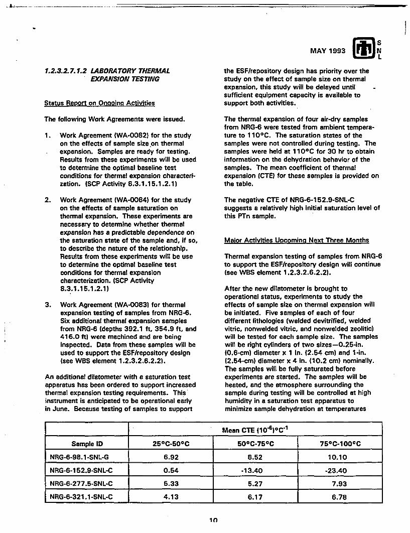
MAY 1993
7.2.3.2.7.1.2 LABORATORY THERMALEXPANSION TESTING
Status Report on Ongoing Activities
the ESF/repository design has priority over thestudy on the effect of sample size on thermalexpansion, this study will be delayed untilsufficient equipment capacity is available tosupport both activities.
The following Work Agreements were issued.
1. Work Agreement (WA-0082) for the studyon the effects of sample size on thermalexpansion. Samples are ready for testing.Results from these experiments will be usedto determine the optimal baseline testconditions for thermal expansion characteri-zation. (SCP Activity 8.3.1.15.1.2.1)
2. Work Agreement (WA-0084) for the studyon the effects of sample saturation onthermal expansion. These experiments arenecessary to determine whether thermalexpansion has a predictable dependence onthe saturation state of the sample and, if so,to describe the nature of the relationship.Results from these experiments will be useto determine the optimal baseline testconditions for thermal expansioncharacterization. (SCP Activity8.3.1.15.1.2.1)
3. Work Agreement (WA-0083) for thermalexpansion testing of samples from NRG-6.Six additional thermal expansion samplesfrom NRG-6 (depths 392.1 ft, 354.9 ft. and416.0 ft) were machined and are beinginspected. Data from these samples will beused to support the ESF/repository design(see WBS element 1.2.3.2.6.2.2).
An additional dilatometer with a saturation testapparatus has been ordered to support increasedthermal expansion testing requirements. Thisinstrument is anticipated to be operational earlyin June. Because testing of samples to support
The thermal expansion of four air-dry samplesfrom NRG-6 were tested from ambient tempera-ture to 1 100C. The saturation states of thesamples were not controlled during testing. Thesamples were held at 11 00 C for 30 hr to obtaininformation on the dehydration behavior of thesamples. The mean coefficient of thermalexpansion (CTE) for these samples is provided onthe table.
The negative CTE of NRG-6-152.9-SNL-Csuggests a relatively high initial saturation level ofthis PTn sample.
Maior Activities Upcoming Next Three Months
Thermal expansion testing of samples from NRG-6to support the ESF/repository design will continue(see WBS element 1.2.3.2.6.2.2).
After the new dilatometer is brought tooperational status, experiments to study theeffects of sample size on thermal expansion willbe initiated. Five samples of each of fourdifferent lithologies (welded devitrified, weldedvitric, nonwelded vitric, and nonwelded zeolitic)will be tested for each sample size. The sampleswill be right cylinders of two sizes-0.25-in.10.6-cm) diameter x 1 in. (2.54 cm) and 1-in.(2.54-cm) diameter x 4 in. (10.2 cm) nominally.The samples will be fully saturated beforeexperiments are started. The samples will beheated, and the atmosphere surrounding thesample during testing will be controlled at highhumidity in a saturation test apparatus tominimize sample dehydration at temperatures
Mean CTE (10)C
Sample ID 25C-50 C 50 C-750C 75 C-100 C
NRG-6-98.1 -SNL-G 6.92 8.52 10.10
NRG-6-152.9-SNL-C 0.54 -13.40 -23.40
NRG-6-277.5-SNL-C 5.33 5.27 7.93
NRG-6-321.1-SNL-C 4.13 6.17 6.78
10
MAY 1993
below the nominal boiling temperature of 100 C.When this temperature is reached, temperaturewill be held constant and the sample allowed todehydrate until the length stabilizes. Heating willbe restarted and continue until the temperaturereaches 300 C; then the sample will be cooled toambient temperature (25 C). (SCP Activity8.3.1.15.1.2.1)
After the study of the effects of sample size onthermal expansion is completed, the study of theeffects on sample saturation will be initiated.Five samples each of four different lithologies(welded devitrified, welded vitric, nonweldedvitric and nonwelded zeolitic) will be tested.Three initial saturation states will beexamined-fully saturated, air-dry, and oven-dry.The Amosphere surrounding the sample duringtesting will be controlled at high humidity in asaturation test apparatus to minimize sampledehydration at temperatures below the nominalboiling point of 100 C. When this temperature is
reached, the temperature will be held constantand the sample allowed to dehydrate until thelength stabilizes. Heating will be restarted andwill continue until 125 C is reached; then thesample will be cooled to ambient temperature.(SCP Activity 8.3.1.15.1.2.1)
1.2.3.2.7.1.3 LABORATORY DETERMINATIONOF MECHANICAL PROPERTIES OFINTACT ROCK
Major Accomplishments
SAND92-1810, "Unconfined CompressionExperiments on Topopah Spring Member Tuff at22 C and a Strain Rate of 10 s : Data Report,"has completed management review and was sentto the Project Office on May 13, satisfyingMilestone OS46. (SCP Activity 8.3.1.15.1.3.2)
Status Report on Ongoing Activities
New England Research, Inc. (NER) is conducting astudy of time-dependent deformation involvinghigh-temperature experiments at creep and low-strain rate conditions. The most recent series ofexperiments consists of at least six samples ofTSw2 to be tested at a pore pressure of 4.5 MPa,a confining pressure of 5 MPa, and a maximumconstant differential stress of 80 MPa. Theexperiments are performed initially at roomtemperature and then at 250 C. The thirdexperiment was completed in May, and the fourthsample is being prepared for testing beginning inJune. (SCP Activity 8.3.1.15.1.3.2)
NER is conducting a study of the mechanicalproperties of tuff samples from a series ofdrillholes (denoted as NRG, north ramp geology).These holes are located along the length of theplanned position of the north ramp of the ESF.The samples are machined, dried, and saturatedprior to testing at uniaxial and triaxial conditions.Sample porosity is calculated from the dry andsaturated bulk densities. Compressional andshear wave velocities were also measured onboth the dry and saturated samples. Othersamples are being tested for average graindensities and in indirect tensile (Brazil)experiments. The first series of unconfinedexperiments were completed in May on 22samples of core from USW NRG-6 (depthsranging from 22 ft to 329 ft). (SCP Activities8.3.1.15.1.3.1 and 8.3.1.15.1.3.2)
R. Price was in White River Junction, VT, on May19 and 20 to meet with the staff at NER.Discussions centered on the results of testingtime-dependent mechanical properties and theexamination of rock and test results from core
11
MAY 1993
recovered from the series of NRG drillholes. (SCPActivities 8.3.1.15.1.3.1 and 8.3.1.15.1.3.2)
1.2.3.2.7.1.4 LABORATORY DETERMINATIONOF THE MECHANICALPROPERTIES OF FRACTURES
Major Activities Upcoming Next Three MonthsStatus Report on Onpoina Activities
R. Price and two members of the NER staff willbe in Madison, WI, in late June to attend the 34thU.S. Symposium on Rock Mechanics (June 27through 30 at the University of Wisconsin-Madison). They will be presenting a paperentitled "The Influence of Strain Rate and SampleInhomogeneity on the Moduli and Strength ofWelded Tuff." (SCP Activity 8.3.1.15.1.3.2)
SAND92-0119, "Experimental Comparison ofLaboratory Techniques in Determining BulkProperties of Tuffaceous Rocks," has beenrevised in response to technical and editorialreviews. The document revision is beingconsidered by the technical reviewers and shouldbegin management review in June. tSCPActivities 8.3.1.15.1.3.1 and 8.3.1.15.1.3.2)
A series of experiments have been performedunder triaxial conditions to compare the results ofthis experiment technique to the results observedusing the rotary friction method. Rough fractureswere created in three right-circular cylinders byline loading at an inclination of approximately 30to the cylinder axes. These samples were testedat constant normal stress by initially loading thesample in hydrostatic compression and thenconstantly decreasing the confining pressurewhile loading the sample axially. The data onstiffness, dilatancy, and strength are beinganalyzed. (SCP Activity 8.3.1.15.1.4.2)
Major Activities Upcoming Next Three Months
The draft of a new standard test method,"Standard Test Method for Normal and ShearStiffness of Rock Fractures Using aCompression/Rotary Shear Apparatus," wassubmitted to American Society for TestingMaterials (ASTM) committee D-18 on Soil andRock Properties and has completed the firstreview and vote by subcommittee D1 8.12 onRock Mechanics. The results of this review willbe discussed at the committee meetings inAtlanta, GA, on June 22 and 23. (SCP Activities8.3.1.15.1.4.1 and 8.3.1.15.1.4.2)
SAND92-2333, "The Effect of Sliding Velocity onthe Mechanical Response of Artificial Joints inTopopah Spring Member Tuft," is being revised inresponse to the comments generated duringtechnical and editorial review. (SCP Activity8.3.1.15.1.3.2)
A journal article, "Simple Mathematical Model of aRough Fracture," is being drafted and will besubmitted to the Project Office for review in thenext two months. (SCP Activities 8.3.1.15.1.4.1and 8.3.1.15.1.4.2)
12
MAY 1993
1.2.3.2.8.3.3 GROUND MOTION FROMREGIONAL EARTHQUAKES ANDUNDERGROUND NUCLEAREXPLOSIONS
Status Report on Ongoing Activities
1.2.3.6.2.1.6 FUTURE REGIONAL CLIMATEAND ENVIRONMENTS
Major Accomplishments
The transition plan for consolidating PacificNorthwest Laboratory (PNL) efforts on globalclimate modeling into a single SNL effort wastransmitted for Project Office review, satisfyingMilestone OS50.
Status Report on Ongoing Activities
The study plan for ground motion regionalearthquake and underground nuclear explosionswill be revised and updated to reflect the newESF design and revised approaches to modeldevelopment.
PACs planning and a review of the SCP annualplan draft were completed. Interactions with PNLto define transition product deliverables wereinitiated. Procurement planning was also initiatedto obtain an FY94 contract with the NationalCenter for Atmospheric Research (NCAR). Plansfor preparing a new study plan for this work arebeing developed and discussions have been heldwith NCAR regarding resolution of outstandingQuality Assurance (QA) deficiencies.
Major Activities Upcoming Next Three Months
The study plan draft will be prepared and NCARQA deficiencies will be resolved.
Issues/Potential Problems Needing Resolution andPotential Impacts
Insufficient funding remains in this WBS elementto accomplish FY93 deliverables. A letter hasbeen sent to YMP requesting additional funds.
13
MAY 1993
1.2.4 REPOSITORY
The objective of the Repository element includes work scope related to the repository component of thephysical system including the repository operations system, the underground facility component of theengineered barrier system, the access/borehole seals, and the monitoring system component of the performanceevaluation system. The Repository element is comprised of nine tasks: Repository Coordination and Planning(1.2.4.1.1), Excavation Investigations (1.2.4.2.1.1.1), In Situ Thermomechanical Properties (1.2.4.2.1.1.2),In Situ Mechanical Properties (1.2.4.2.1.1.3), In Situ Design Verification (1.2.4.2.1.1.4), Rock Mass Analyses(1.2.4.2.1.2), Certification of Design Methods (1.2.4.2.3.1), Design Analysis (1.2.4.2.3.2), and Sealing andDesign Requirements (1.2.4.6.1).
Status Report on Ongoing Activities
Work on the initial drafts of study plans8.3.1.15.1.6, "In Situ ThermomechanicalProperties" and 8.3.1.15.1.7, "In Situ MechanicalProperties," continued.
SNL staff continues to work with theManagement and Operations contractor (M&O)and staff from other participant organizations todevelop a plan for resolving numerous issuesrelated to the thermal loading of the potentialrepository. As part of this work, SNL isparticipating in an effort to review current thermalgoals and develop a tentative set of revised goalsfor advanced conceptual design (ACD). SNL isleading the effort to examine two goals related tothermal/structural interactions. In the pastmonth, simplified numerical computations werecompleted to define certain bounds on the near-field temperatures. Because of possibly largechanges in thermal expansion of the host rock atelevated temperatures, the stability of the rockmass In emplacement drifts and boreholes mustbe examined. The recent analyses evaluated rockmass stresses around drifts and compared themto nominal failure criteria. As a result of thisevaluation, initial recommendations for revisedthermal goals were transmitted to the M&O forincorporation into their study.
SNL staff continued work on a series of analysesin support of the design of the ESF north ramp.Three-dimensional thermal/structural analyses ofthe repository to assess the impact of thepotential repository thermal loading on the ESF
drifts have been completed. Results will supporttwo-dimensional analyses of several crosssections of the ESF north ramp to evaluate long-term stability. Geotechnical data from the NRGholes will be incorporated into the analyses. Theanalyses are expected to provide input for the90% design review in August 1993.
SNL staff continued construction monitoringactivities at the ESF starter tunnel under studyplan 8.3.1.15.1.8. In the past month, seismicrecords from construction blasting were recorded,rock mass quality estimates for the first 100 ft oftunnel were developed, and locations wereselected for the first two stations of rock boltload cells and bolts were installed.
Major Activities Upcoming Next Three Months
Significant effort will be required to implement thegeotechnical monitoring effort in the startertunnel. (SCP SP 8.3.1.15.1.8)
ESF design analyses will be completed.
Other Items to Report
SNL is continuing temporary monitoring of rockmass movement as the ESF starter tunnel isexcavated. Several sets of tape extensometerpins have been installed to monitor close of thepilot heading. This work is not part of the designverification study plan (8.3.1.15.1.8), but it issimilar in nature to the more permanent moni-toring that will be installed under the study plan.This temporary monitoring is being conductedunder WBS element 1.2.6.1.1.
14
MAY 1993
1.2.4.2.1.1.1 EXCAVATION INVESTIGATIONS 1.2.4.2.1.1.2 IN SITU THERMOMECHANICALPROPERTIES
Status Report on Ongoing ActivitiesStatus Report on Ongoing Activities
Staff began incorporating changes to study plan8.3.1.15.1.5, "Excavation Investigations," inresponse to comments received from ProjectOffice reviewers.
Major Activities Upcoming Next Three Months
Staff continued work on the rough draft of studyplan 8.3.1.15.1.6, "in Situ ThermomechanicalProperties. "
Proposed resolutions written in response totechnical comments from internal SNL technicalreview for the SAND report entitled "TestInstrumentation for the ESF In SituThermomechanical Experiments" were returned tothe technical reviewers.
Major Activities Upcoming Next Three Months
Staff will work with Project Office reviewers tofinalize the study plan 8.3.1.15.1.15, "ExcavationInvestigations."
Staff will continue drafting study plan8.3.1.15.1.6.
Staff will produce a final draft of "TestInstrumentation for the ESF In SituThermomechanical Experiments" that incorporatescomments from reviewers.
Under LANL coordination, staff will work withLLNL staff to consolidate SNL's ESFthermomechanical testing with LLNL'shydrothermal testing, if possible.
Plans and objectives of the experiments containedin study plan 8.3.1.15.1.6, "In Situ Thermo-mechanical Properties," will be presented to theNuclear Waste Technical Review Board (NWTRB)meeting that will be held on July 13 and 14.
15
MAY 1993
1.2.4.2.1.1.3 IN SITU MECHANICALPROPERTIES
1.2.4.2.1.1.4 IN SITU DESIGN VERFICATION
Status Report on Ongoing ActivitiesStatus Report on Ongoing Activities
Staff continued work on the rough draft of studyplan 8.3.1.15.1.7, "In Situ MechanicalProperties."
Major Activities Upcoming Next Three Months
Staff commenced construction monitoring of theESF north ramp starter tunnel. The monitoringplans include seismic monitoring for blasting, rockquality determination, ground support systemperformance evaluations, and excavation closuremonitoring for stability assessments. In thisreporting period, seismic blast monitoring androck quality determination were conducted.
Maior Activities Upcoming Next Three Months
Staff will continue drafting study plan8.3.1.15.1.7.
Staff will continue to field construction monitoringactivities and to procure and designinstrumentation and a data-acquisition systemneeded for future monitoring activities.
A presentation of construction monitoringactivities will be presented at the 34th U.S. RockMechanics Symposium on June 27 through 30.
16
MAY 1993
1.2.4.2.1.2 ROCK MASS ANALYSES
Status Report on Ongoing Activities
In work related to laboratory testing involvingsmall polycarbonate models, this month wasspent finishing a draft of a SAND report entitledGeometrical Moire Method of Strain Analysis
with Displacement Discontinuities" (Level 3Milestone OS18). This report describes themethods and software developed to acquire andanalyze the data from tests of layeredpolycarbonate models.
report is being drafted and should begin SNLreview soon.
SNL support of the M&O's design efforts for thenorth ramp continued in May. The majority of thestatic analyses have been conducted. In theseanalyses, the in situ, thermal, and equivalentseismic loads were applied to a number of northramp cross sections. The seismic loads areclearly the dominant loads at most of the crosssections.
Major Activities Upcoming Next Three Months
Next month, SNL staff will analyze the data fromtests conducted over the last few months and willbegin writing a report on these tests.
A study comparing the surface characteristics ofnatural fractures to the frictional data gathered onreplicas of the surfaces is continuing. This studywill place special emphasis on determiningwhether the fitting parameters in the Bartonmodel for frictional behavior have physicalsignificance. This is being accomplished byinvestigating the effect on fracture shear strengthand dilation of varying three parameters: normalstress, roughness, and the strength of the rockmaterial. The majority of the experimental workis being carried out by a University of Colorado(CU) graduate student in the GeomechanicsDevelopment laboratory at SNL. The series ofeleven rotary shear experiments were completedin March. The results are being organized, andanalysis will continue for the next several weeks,leading to the data being presented in a SANDreport.
Testing, data reduction, and analysis will beginfor a set of layered plate experiments.
Static and dynamic analyses will be conducted tosupport the design of the north ramp.
A series of experiments designed to study theeffects of a nonstandard loading condition onfrictional properties were conducted at CU in1992. SAND92-1853, "Effect of BoundaryConditions on the Strength and Deformability ofReplicas of Natural Fractures in Welded Tuff:Data Report," details the experiment techniquesand the resulting data. This SAND report hascompleted management review and is beingrevised. The first of two analysis reports,SAND92-2247 entitled "Effect of BoundaryConditions on the Strength and Deformability ofReplicas of Natural Fractures in Welded Tuff:Comparison Between Predicted and ObservedBehavior," has been through technical review andis in management review. The second analysis
17
MAY 1993
1.2.4.2.3.1 CERTIFICATIONS OF DESIGNMETHODS
Status Report on Ongoing Activities
Work at CU in developing joint constitutivemodels is continuing. This work began by CUconducting a literature search to identify the bestavailable joint constitutive model in the literature.This month, experimental data developed in WBSelement 1.2.4.2.1.2-has been fitted to Plesha'sjoint constitutive model, and the model wasincorporated into a finite element code.
In other work at CU, modifications to the discreteelement code DDA are being performed toimplement the sub-block concept. This month anaugmented lagrangian method was included tohandle block-to-block-contact. The convergencerate is low, so CU is checking for possible codingerrors. CU is also looking at the work performedby J. Jung (SNL) to see how the augmentedlagrangian method can be used to perform sub-blocking (i.e., breaking large blocks into smallerblocks).
In a separate activity the coupled finite element -boundary element research is continuing. Thismonth J. R. Koteras (SNL implemented a newtonouter loop to the JAC2D code, which allows theexplicit solvers to operate on linear systems asopposed to nonlinear systems. Incrementalsolutions of linear problems were obtained thismonth. Incremental solutions of standardplasticity problems are currently being attempted.SNL staff expects that the code will be able tosolve these simple norlinear problems early nextmonth. Following that coupling nonlinear finiteelements to linear boundary elements will beattempted.
B. J. Thorne (SNL) has been working to improveSNL's continuum joint model. This month SNLstaff finished a review of the literature andobtained a copy of another model that has somefeatures that are different from SNL's model.SNL plans to test this model to determine if itperforms better than SNL's model and, if so, todetermine how these features can be incorporatedinto SNL's model.
Maior Activities Upcoming Next Three Months
Testing of a discrete element code sub-blockingconcept will continue. Implementation of the sub-blocking concept into the DDA code will continue.
Development will continue of a coupled finiteelement-boundary element technology to assesshow to couple nonlinear finite elements to linearboundary elements.
Work on a SAND report to document JAC2D willbegin in June.
18
MAY 1993
1.2.4.2.3.2 DESIGN ANALYSIS 1.2.4.6.1 SEALING AND DESIGNREQUIREMENTS
Status Report on Ongoing ActivitiesStatus Report on Ongoing Activities
The development of near-field thermal/structural/seismic models for use in supporting the design ofthe ESF's north ramp continued. Analysesassuming equivalent-static and dynamic seismicloads are being pursued. Output from this activityis expected to be ready for transmittal to theM&O design team within the next four to sixweeks.
Investigation continued on quantifying theimportance to structural predictions of anobserved increase in measured thermal expansiondue to polymorph silica phase transformations.The results of the analyses are intended forincorporation into the ongoing reevaluation of SCPthermal goals.
The activities during the reporting period includedpreparing a Work Agreement for the completionof the borehole strategy report, receiving text andartwork from Creative Computer Services, refor-matting the text for the borehole strategy report,preparing and editing sections of the report. Newfigures for Chapter 3 were drafted and check-prints prepared. Additional information wasobtained concerning the completion of newboreholes.
19
MAY 1993
1.2.5 REGULATORY
The objective of the Regulatory element is to assure site-related compliance with Nuclear RegulatoryCommission agreements, requirements, and policies; evaluate the performance of the natural barriers,engineered barriers, and total systems for meeting regulatory standards; and manage, maintain, and accumulatetechnical data and information produced by site characterization, design development, and performanceassessment activities for the project. The Regulatory element is comprised of 11 tasks: RegulatoryCoordination and Planning (1.2.5.1), Site Characterization Program (1.2.5.2.2), Technical Database Input(1.2.5.3.5), Total System Performance Assessment (1.2.5.4.1), Repository Performance Assessment(1.2.5.4.3), Site Performance Assessment (1.2.5.4.4), Interactive Graphics Information System (1.2.5.4.5),Development and Validation of Flow and Transport Models 01.2.5.4.6), Support Calculations for PostclosurePerformance Analyses (1.2.5.4.7), Development and Verification of Flow and Transport Codes (1.2.5.4.9), andSpecial Projects (1.2.5.5).
1.2.5.1 REGULATORY COORDINATION AND 1.2.5.2.2 SITE CHARACTERIZATION PROGRAMPLANNING
Status Report on Ongoing ActivitiesSignificant Meetings Attended
The eighth semiannual progress report wasSNL staff attended a meeting in Las Vegas, NV, reviewed at M&O request.to discuss elements of the PerformanceAssessment (PA) Annual Plan for 1994 with theM&O and LLNL.
Status Report on Ongoing Activities
In addition to providing routine coordination andplanning support to regulatory activities, staff aredeveloping detailed workscopes and deliverablesfor 1.2.5 WBS elements to be included in the PAAnnual Plan. Data needs and linkages with otherparticipants are also being identified.
20
MAY 1993
1.2.5.3.5 TECHNICAL DATABASE INPUT 1.2.5.4.1 TOTAL SYSTEM PERFORMANCEASSESSMENT
Significant Meetings AttendedSignificant Meetings Attended
On May 6, staff attended a meeting with SNLYMP personnel affiliated with database manage-ment activities. This meeting addressed issuesrelated to identification of developed data,disposition of the Reference Information Base(RIB), and the feasibility of appointing a databasecoordinator.
Major Activities Upcoming Next Three Months
On June 3, staff will attend a technical databaseworking group meeting at the Project Office,followed by an orientation session with GENISESpersonnel.
The FY94 budget needs for WBS element1.2.5.3.5 will be determined.
Issues/Potential Problems Needing Resolution andPotential Impacts
Members of the SNL staff attended the YMPColloid Workshop, held May 3 through 5 in SantaFe, NM. "Colloids: A Performance-AssessmentPerspective" was presented by M. Wilson of SNL.
SNL staff attended the Technical Workshop onNear-Field Performance Assessment, atCadarache, France, from May 11 to 13.Attendees included representatives from U.S.,Swedish, Swiss, German, French, Finnish, UK,and Dutch waste-disposal programs. Thepurposes of the meeting were to review theaspects of near-field performance assessment, todevelop themes that should be pursued, and toidentify areas common to the programs that mightbe appropriate for collaboration. Topics includednear-field environment, releases, transport,modeling, and performance assessment (PA)integration. The workshop participants were splitinto interest groups to discuss the topics in detailand develop recommendations. Most of theemphasis was on the European programs (andtheir design and environmental conditions);consequently, most of the discussion wasconcerned with saturated repositories withbentonite backfill and reducing groundwaterconditions. A member of the SNL staff was inthe PA integration group, so YMP interests wereincluded in their recommendations. Areas ofmutual interest include many of the scenarioclasses (e.g., near-field hydraulic, radiolytic, andchemical processes; volcanic processes; reposi-tory operations), some aspects of the geochemis-try (e.g., alteration of near-field hydraulicproperties by the engineered barrier system),glass-waste dissolution, and salt-repositorycharacteristics. A survey and review documentand a workshop summary are being prepared bythe organizers to be published within a fewmonths.
Modification of Technical Data Information Forms(TDIFs) is required to facilitate usage by technicalpersonnel. Also, the TDIF backlog must beresolved, and the future disposition of TDIFsubmittals (paper vs. electronic) should bedecided.
An SNL staff member attended the HydrologyIntegration Task Force meeting held in Denver,CO, on May 17 and 18. The topic of focus wasthe C-well testing, the current results, and futuretest plans.
SNL personnel coordinated and hosted a meetingon May 26 with participants from USGS,
21
Raytheon Servies of Nevada (RSN), andM&O/INTERA. The purpose of this meeting wasto discuss the best approach for representinginfiltration and water flow at Yucca Mountainresulting from both current and fixture climaticconditions. The results of this discussion will beused as the basis for the percolation flux used inthe second cycle of the Total SystemPerformance Assessment (TSPA-2).
SNL staff attended a meeting on May 26 atLawrence Uvermore National Laboratory (LLNL)with representatives from LLNL and the M&O.The objective of the meeting was to formulate asource term for use in the M&O version of theTSPA. The result of the meeting was that theM&O will use the same source term that hadbeen previously determined by intractionsoccurring between SNL and LLNL in February.Also, a meeting was set for early une tocorrelate the LLNL hydrothermal calculations withSNL thermal data to determine the, hydrothermalprofiles to be used in the TSPA source term.
In an ongoing effort, SNL staff members hosted ameeting on May 27 and 28 with LLNL staff. Theobjective was to couple LLNL's Yucca MountainIntegration Model (YMIM) source model to SNL'stransport models for the TSPA (both TOSPAC andWEEPTSA). There are a number of difficultieswith this integration, but the collaboration isgoing well and this interface between SNL'sprograms should make future generations ofYMIM easier to incorporate.
Status Report on Ongoing Activities
Information on the TSPA problem setups(including repository area and heat output,stratigraphy, and material properties) has beentransmitted to Disposal Safety Inc. (DSI). Usingthis input, they have begun the gas-flowcalculations for TSPA-2.
The weeps" model was modified. to incorporateLLNL's source-term model, YMIM. Modificationsto the weeps model to incorporate thermal-effectsdata have also been started. Specifics of themodification include incorporating the number ofcontainers outside the boiling isotherm as afunction of time, the volume of rock encom-passed by the boiling isotherm, and the tempera-ture histories of representative containers.
MAY 1993
For the composite-porosity flow model, staffbegan determining a new set of columns for thethree potential repository footprints, based onvariations in power densities. Reconfiguration ofthe footprint has required construction of differentstratigraphic cross sections from which to drawthe columns used for the one-dimensionalcalculations. Staff also began incorporatingdistributions for the hydrogeologic parameters ofthe stratigraphic units into the TOSPAC inputfiles.
SNL staff is developing a source term that reflectsthe proper weighting of age and burn-up for spentfuel and also are attempting to include glassifiedhigh-level waste for TSPA-2. There will be tworepresentations of the source term. The human-intrusion source term will be composed of all ofthe inventory, while the aqueous flow andvolcanism calculations will utilize indicatornuclides, as discussed in SAND92-2431.
The human-intrusion direct release model,currently in development, will calculate releasesdue to drilling into a repository where the wastepackage configuration is based on the fourvariations of the thermal loads and emplacementschemes. Preliminary results of calculations forthe in-drift emplacement model indicates thatinterception of the much larger waste packagemay lead to releases of very high amounts ofradionuclides in any one drilling event.
SAND93-0852, The Appropriateness of One-Dimensional Yucca Mountain HydrologicCalculations," has been through technical review.The reviewer's comments have been incorpor-ated. The comments from the technical editor arebeing addressed.
In collaboration with Dr. Nilson (S-CUBED), staffformulated a model for moisture (liquid and vapor)movement in fractured media driven by fluctua-tions in barometric pressure. The barometricfluctuations will be assumed periodic in time,allowing an enormous simplification in treating acoupled fracture and matrix system. In essence,the vertical transport along the fractures can beapproximated in such a way to decouple thehorizontal transport in the matrix blocks. Aformulation for describing multiphase flow ofwater, air energy in a porous material has beendeveloped. This particular formulation isappropriate for numerical treatment when coupledto the simplified description of time-periodic flow
22
MAY 1993
in the fracture system. A method-of-line code isbeing written to obtain numerical solutions to thefracture/matrix problem.
The nominal flow scenario-selection documentshould be ready for internal review by thebeginning of June after final revision of figures,flow charts, and text.
1.2.5.4.3 REPOSITORY PERFORMANCEASSESSMENT
Status Report on Ongoing Activities
Progress continued on an evaluation of the LLNL"extended dry" concept. Calculations completedduring this reporting period address theimportance of multiple material propertydesignations (layering) in thermal models.
Waste stream information was obtained for use incalculations designed to support the M&O'sthermal loading system study. Preliminary modeldevelopment is proceeding; however, significantprogress has been delayed due to a lack ofguidance regarding sizes and locations ofunderground openings.
Near- and far-field thermal calculations are beingdeveloped for use in the next iteration of theTSPA. The goal of these analyses is to provideestimates of representative waste packagetemperatures, the number of packages protectedby a boiling front as a function of time, andvolumetric dry out.
Staff continued to participate on several teams ofthe Site Characterization Plan (SCP) ThermalGoals Working Group and provided draft input forthe Thermal-Mechanical Team and the Opera-tions, Safety, and Environment Team on May 25.
23
MAY 1993
1.2.5.4.4 SITE PERFORMANCE ASSESSMENT
Major Accomplishments
SAND88-7054, "Processes, Mechanisms,Parameters, and Modeling Approaches forPartially Saturated Flow in Soil and Rock Media,"by J. S. Y. Wang and T. N. Narasimhan, iscomplete and is being printed.
Status Repor in Ongoing Activities
To support and visually complement the numericalanalyses, graphical representations of the basicstatistics and beta probability distributions havebeen developed (histograms and beta probabilitydistribution plots, both normal and log normal) forinclusion in the second-cycle TSPA report.
Matrix saturated hydraulic conductivity and matrixporosity data for Spearman Rank Correlationshave been parsed according to hydrogeologicunits and run for coefficients. Analyses of thecoefficients for significance are currently beingevaluated.
I
Geohydrologic Data Analysis: SNL staffperforming TSPA modeling have been providedwith initial basic statistics, beta distributionparameters, and upscaled beta distributionparameters for the following matrix materialproperties and beta distribution classes:
* Matrix Porsity-Normal* Saturated Matrix Hydraulic Conductivity-Log
Normal* van Genuchten Parameters:
- Matrix Air Entry (alpha)-Log Normal- Matrix Saturation/Desaturation (beta)-Log
Normal- Matrix Residual Degree of Saturation
(Sr)-Exponential* Bulk Density-Normal (parsed according to
hydrogeologic unit; statistics anddistributions are pending other analystpriorities)"
The basic statistics report the number of data,expected value (mean), coefficient of variation,and maximum and minimum of the data. Fromthe basic statistics, beta probability distributionparameters were derived by the RS1 statisticalpackage. If abnormal distribution could not begenerated because of the lack of sufficient data,Shannon's maximum entropy routine wasemployed reporting the mean, the maximum andminimum, and the alpha and beta curveparameters of the distribution. Then the curveparameters were upscaled for the beta probabilitydistribution parameters that account for thevertical correlation length and mean thickness ofthe hydrogeologic units. Data reported are themean thickness of the unit, upscaled coefficientof variation, upscaled alpha and beta distributionparameters, and model specific input parameters(p and q).
Bulk hydrogeologic conductivity distributions forthe drillholes with pump tests resulting in bulkpermeability or conductivity data have beenidentified. The probability distributions weregenerated as the matrix parameters were, butwithout the upscaling (due to the tests beingaccomplished over integral, thick sequences).Holes USW H-1, 3, and 4; UE-25b1 and p1; J-13;and USW G-4 were used for saturated bulkconductivity values. Holes USW UZ-1 andUE-25a#4 were used for air permeability dataderived from barometric fluctuations. Only datarepresentative of single, definable stratigraphicunits were used. If pump tests crossedstratigraphic units, the data were not used.
Fracture data from downhole measurements havebeen analyzed for fracture distributions from USWG-4 as a test case to evaluate utility to the PAproblem. An attempt has been initiated to derivethe applicable information to correlate fractureaperture size as a function of the second momentof log saturated permeability versus log pore-size,according to an approach developed by J. Wang(LBL). If this approach is successful, a morerealistic range of aperture size would be availableto the modelers.
Data Base and GIS Management: The PAdatabase currently is in a low-level maintenancemode with limited activity. The GIS system,ARC/INFO, has had additional coverages devel-oped, adding proposed drillhole locations withrelation to topographic features, proximity toroads, existing drillhole locations, and otheraffecting relationships. The GIS staff supported awalk-through visit by the President of SNL, A.Narath, with a demonstration of some of the GIScapabilities for Yucca Mountain data.
24
MAY 1993
Probability Modeling: Modifications to theentropy fit program were made in response toproblems discovered during generation of theprobability distributions for TSPA II. The changesincluded:
1 )A change in the computation of normalizingconstant from adaptive integration to ananalytical formula. The change is morecomplicated for bimodal and trimodal betadistributions but has also been completed.
2) Display of the cubic line search iteration hasbeen added and a maximum number ofiterations.
3) The maximum number of nonlinear iterationshas been added to the input file so it can beadjusted by the user.
4) Error tolerances were adjusted to increaserobustness. Step size used in computingderivatives was made more robust.
Staff completed modifications of probabilitysoftware originally installed on the VAX.Specifications for the user interfaces are beingdeveloped for experience gained during theelicitations. A user interface in an RS/1 shell hasbeen written and installed on the PC.
The report entitled Progress Report on StochasticModeling: Generation of Correlated RandomVectors with Multivariate Normal and BetaDistributions," by J. Sun and M. Harr, hasundergone internal technical review. The reportdescribes work SNL has been supporting under aresearch grant to Purdue Research Foundation.Purdue will be supplying software with a graphicaluser interface later this summer.
Performance Assessment Support: Work hasbegun on producing stratigraphies for the revisedcolumns for the TSPA. Computation of rankcorrelations for porosity and saturated matrixconductivity have been completed for each unit.
Work has continued on the east-west INTRAVALcross section with the gradational change inporosity in the shardy base added. The adaptivegrid algorithm GAG was tried on the crosssection, but produced poor results. Changes arebeing made to GAG to improve the results.
1.2.5.4.5 INTERACTIVE GRAPHICSINFORMATION SYSTEM
Major Accomplishments
Staff attended the 1993 Environmental SystemsResearch Institute (ESRI) Conference andparticipated in various ARC/INFO workshops,learned about upcoming ESRI software features,and provided input into future development.
Status Report on Ongoing Activities
Development is continuing on a series ofcoverages showing the starter tunnel, alcoves,and instrument locations.
Staff continues to identify users of the VAX 3600to help plan the retirement of the computer. TheCalma/DDM thermal/mechanical model is notscheduled to be made available beyond FY93.
A workload spike on color printers causedqueueing problems and excessive delays. Staff isevaluating several replacement options toaccommodate the ever-increasing workload.
The following job has been completed:
* Job 404 for D. L. Eley - Create ESF startertunnel plan
Major Activities Upcoming Next Three Months
Alternate platforms for users of the VAX 3600will be found. Migration to the other platform willbe accomplished, and the Calma software will beeliminated.
Staff will plan and begin implementing a userenvironment that provides access to dataobtained from instruments placed in the tunnels atYucca Mountain. The tool will enable users toutilize several tools to manipulate, visualize, andoutput the data as needed.
The following jobs are in progress:
* Job 397 for D. L. Eley - Convert GTMs toARC/INFO
* Job 398 for D. Guerin - Hydrogeologicdrillholes
25
MAY 1993
* Job 401 for L. H. Skinner - Contours of Yucca 1.2.5.4.6 DEVELOPMENT AND VALIDATION OFMountain FLOW AND TRANSPORTMODELS
* Job 405 for C. A. Rautman - Rebuild TSw1model per new input
* Job 407 for M. L. Jones - Add new data All activities addressed in this monthly statuscoverages report support SCP Section 8.3.5.12.2.1.1.
* Job 408 for L. E. Shephard - Profile throughUSW G-4
Significant Meetings Attended
R. J. Glass and M. J. Nicholl attended the 1993Spring Meeting of the American GeophysicalUnion held in Baltimore, MD, during the week ofMay 24 through 28. They presented Influenceof Fracture Saturation and Wetted Structure onFracture Permeability," by M. J. Nicholl and R. J.Glass; Infiltration Flow Instability in UnsaturatedFractures," by M. J. Nicholl and R. J. Glass; and"Gravity-Driven Fingering in Rough-WalledFractures: Analysis Using Modified PercolationTheory, by R. J. Glass.
Status Report on Ongoing Activities
Flow and Transport Through Single Fractures:Development of a methodology to produce epoxycasts of natural fractures continued. Most workwas concentrated on control of the boundaryconditions. A test fracture prepared in April usingexternal manifolds to control inflow and boundaryconditions was subjected to preliminary tests. Itwas observed that the boundary must have asmooth, flat surface to effect an adequate seal.In addition, as the fracture trace will not be astraight line, great care must be taken to assurethat the manifold gasket fully encloses thefracture aperture. Using external manifolds tosatisfy these criteria requires a significant amountof care and forethought during preparation of thesample. Work is progressing toward developmentof a new methodology yielding better control ofboundary conditions with less time expenditure.The test fracture was disassembled and internalmanifolds machined into the fracture surfaces.Preliminary tests using the internal manifoldsshowed excellent promise; efforts to refine thistechnique will continue in June. Evaluation of thewetting, optical, and mechanical propertiescharacteristic of various epoxy formulations andpreparation techniques will also continue in June.
Development of experimental techniques toexplore the effects of air entrapment on fracturepermeability and tracer migration continued.
26
MAY 1993
Hardware to allow acquisition of both high- andlow-resolution images of the test fracture atcontrolled intervals during the experiment wasacquired and installed during May. Low-levelsoftware control of the hardware was alsoimplemented; integration of control into existingimage-acquisition software will proceed in June.The cooling system for the high-resolution camerawas reworked to include filtration of the watersupply. To prevent equipment damage should thesupply of cooling fluid be interrupted during along-term test, a relay was designed to shut offthe camera. Fabrication and installation of therelay should be accomplished in June.
Fracture/Matrix Interaction: Constructioncontinued on an enlarged test chamber tofacilitate larger-scale investigations of fracture-matrix interaction. The new test chamber will becapable of securing multiple fractured rock slabsmeasuring 2 ft by 2 ft with thicknesses -1 in.Efforts have also been made to improve themeans by which various boundary conditions areapplied to the experimental systems (upper fluxboundary and lower prescribed tension boundary).
A joint laboratory program with A. Flint (USGS,YMP test site) and E. Kwicklis (USGS, Denver)has been initiated for investigating unsaturatedflow behavior in fractured volcanic tuff. Theseexperiments will make use of slabs of welded tuffcut from a tuft block previously used in infiltrationstudies conducted by E. Kwicklis. Fracture-matrixinteraction studies will be conducted by intro-ducing water at the top of the natural fracturesthat cut the tuff slab. X-ray absorptiontechniques will then be used to monitor thedeveloping flow field over time.
Experiments have continued in efforts to developreal-time x-ray analysis capabilities. Currently,investigations are conducted in two systems: thesimple x-ray detector/image intensifier system andthe more sophisticated Seimen's Polytron. Thegoal is to achieve a high degree of image contrastin porous systems that have short time constants.
Field, Laboratory, and Numerical Experimentationto Determine Scaling Laws for Effective-MediaProperties in Heterogeneous Media: Efforts arecontinuing on the development of software todrive the automated gas-permeameter test systemas well as the development of a test procedurethat addresses such issues as sampling strategy,calculation of gas permeability from permeameter
data, and data-reduction protocols. A survey ofaccessible rock/heterogeneity types has beenconducted to help guide the selection of blocksamples to use in the initial stages of thisprogram.
Caisson Test: A second systematic study ofsorption of bromine (Br) by the Wedron 510 sandunder carbon dioxide (CO2)-free conditions wascompleted and reduced the uncertainty of the Kdvalue for the conservative tracer for the caissonexperiment. A new technician was trained in thetechniques for lithium (Li) analysis by flameatomic adsorption in preparation for the caissontest. A draft technical procedure for the Uanalysis technique was prepared. Additionalnickel (Ni) sorption data was collected under CO2 -free conditions to calculate surface complexationconstants. Ni sorption experiments using thebatch sorption techniques described in LosAlamos National Laboratory (LANL) DetailedTechnical Procedures TWS-INC-DP-05-R2 andLANL-INC-DP-86-RO were initiated. The datafrom these experiments will be used to calculateretardation factors for use in transport codes suchas TRACR3D and TRANS and will be comparedwith those collected in previous studies at SNL.M. Siegel (SNL) and K. Stetzenbach (UNLV) metto determine the schedule and number of samplesthat will be analyzed at UNLV during the caissonexperiment. The final design of the caisson,including locations of TDR probes and ceramicand hollow fiber solution samplers, wascompleted and submitted to LANL prior to fillingof the caisson.
Reactive Transport Model Development: Linkageof the new version of EQMOD with the flowmodule was completed; the new version of thechemical speciation module contains multiplesorption and ion-exchange sites. Four alternativePCG solvers were incorporated into LEHGC1.1.Testing of both the incorporated new EQMOD andthe PCG solvers is in progress.
Reactive Transport Experimentation:Development of methods to carry out in-situbatch sorption studies in unsaturated mediacontinued. Responses were prepared for theCorrective Action Requests (CARs) that resultedfrom the QA audit that was held at theMassachusetts Institute of Technology in March.
Planning and instrumentation of the reactivetransport laboratory continued. The design of the
27
MAY 1993
unsaturated hanging column experiments wastested with a column of Wedron 510 sand and aUBr tracer. Saturation was determined by a massbalance on the water. Column effluent wascollected automatically by a fraction collectoronce steady flow was established. Analysis forboth Li and Br will be conducted in the first weekof June. A second run using continuous feed ofLiBr solution was initiated to determine
breakthrough curves for U and Br. Analysis ofthe pulse and breakthrough data with thecomputer code CTXFIT will give retardationfactors and dispersivities for Li and Br. Dataacquisition interfaces for collection of real-time pHand water flux data using the LabTech softwareare being developed.
Major Activities Upcoming Next Three Months
IStaff will obtain surface complexation constantsof Br, Li, and Ni by sand to be used in caisson or-in supporting laboratory studies. Li-Ni ionexchange studies with sand will be carried out.Isotherm experiments to determine the linearrange of sorption of tracers will continue, as willsurface potentiometric titration of sand. TheLEHGC code will be implemented on massivelyparallel architecture. Development of a method ofunsaturated Kd measurements with a Turbulamixer will continue, and the method for laserfluorescence measurements of uranium (U) insand and fractured media will be optimized.
Evaluation of the stability of the autotitratorshowed that the drift rate under C02 -freeconditions at pH 7 is sensitive to argon (Ar) flowrate, with high flows producing drift to basic pHand low flows to acidic pH. The optimal Ar flowwas determined, producing drift rates of betterthan 0.001 pH/min at pH 7. This stability isprobably adequate for general potentiometrictitration work. An initial titration curve wasmeasured for raw Wedron 510 sand and showedthat the stirrer can effectively suspend a 1:1solid:solution mixture of electrolyte and sand.The sand settles quite rapidly; therefore, a highstirrer setting is required, possibly leading tograin-to-grain collisions and consequent produc-tion of clay-size particles. Rapid setting alsoinduced a "settling potential" at the pH electrode,causing it to be sensitive to the flow orientation,leading to reading variations of as much as
0.05 pH units. Shielding the electrode from thedirect flow eliminated this problem. Presentefforts are directed toward obtaining a batch ofsand that has been stripped of its carbonatecontent by maintaining it at pH 3 until no furtheradditions of acid are required.
The precipitate formed in the Ni solubilityexperiment was identified as predominantlyNi(OH)2 by x-ray diffraction, but there are twounidentified peaks of minor intensity on the x-raypattern.
28
MAY 1993
1.2.5.4.7 SUPPORTING CALCULATIONS FORPOSTCLOSURE PERFORMANCEANALYSES
Major Accomplishments
ESF PA Analysis No. 13, which addressesconcerns regarding underground water usage fordust control during excavation and fire fighting inthe ESF north ramp, south ramp, and main testlevel tunnels, completed technical review. Also,recommendations for inclusion in Appendix I ofthe ESFDR completed technical and managementreviews and were transmitted to the ProjectOffice.
Testing and numerical simulations for thenonisothermal experiments planned with WBSelement 1.2.5.4.3 will continue.
Other Items to Report
A new ESF PA Analysis (No. 14) investigating thesensitivity of previous analyses to uncertainty inthe hydrologic properties of the nonweldedPaintbrush Tuff has been postponed until Augustto allow staff to participate in the nonisothermalflow experiments. This PA analysis has beenidentified as a potential activity with a Level IIIMilestone for FY94.
Status Report on Ongoing Activities
Preliminary efforts have begun for modelvalidation exercises in nonisothermal flow incollaboration with WBS element 1.2.5.4.3 andthe Department 6115 Flow Laboratory. A seriesof experiments using two different constanttemperature boundaries have begun. Staffmembers are currently learning the codeTOUGH-2 to use for these early efforts.
Preliminary PACS exercises have begun. Potentialactivities, Level III Milestones, and deliverablesfor FY94 have been identified for WBS element1.2.5.4.7. These activities include analyses ofeffects of diesel smoke, grout, and epoxy resinused in the ESF on waste isolation (ESF PAAnalysis No. 1 1); sealing requirements for theESF and boreholes; potential effects of ventilationon waste isolation; and sensitivity of previousanalyses on the material properties used for thePaintbrush Tuff nonwelded unit (PTn) (ESF PAAnalysis No. 14).
Maior Activities Upcoming Next Three Months
ESF Analysis No. 13 will be continuing, with aSAND report (SAND93-1182) to completetechnical and management review by the end ofFY93 (Level III Milestone OS14).
The report SAND92-2248, "Estimations of theExtent of Migration of Surficially Applied Waterfor Various Surface Conditions Near the PotentialRepository Perimeter," will be published.
29
MAY 1993
1.2.5.4.9 DEVELOPMENT AND VERIFICATION 1.2.5.5 SPECIAL PROJECTSOF FLOW AND TRANSPORT CODES
No significant activity this reporting period.Status Report on Ongoing Activities
Code Development: The integrated finitedifference code TOUGH2 (Pruess, 1991) has beenused to makeone-dimensional predictions of themultiphase flow in the vicinity of the proposedunderground nuclear waste repository at YuccaMountain, NV, for times to 10,000 yr. (SCPSubactivity 1 6.2.1.2)
A memo has been written discussing the resultsof these computations. The results can besummarized as follows.
* The two-dimensional global repository problemcan be reasonably approximated by one-dimensional flow for waste burial times up to600 yr.
* The use of a composite model is necessary toobtain computational results that predict dryout in the vicinity of the repository.
* The use of an approximate composite model inTOUGH2 resulted in unrealistic executiontimes.
* The sensitivity of repository dry out to materialproperties will be investigated upon theincorporation of a workable composite materialcharacteristic model in the SNL version ofTOUGH2. Staff has been in contact with J.Nitao of LLNL regarding the composite modelused in VTOUGH. He is sending a listing oftheir composite model.
Software QA Staff have completed the SoftwareConfiguration Management Course (CS777). (No
SCP activity)
SNL staff are continuing to participate in thesoftware QATeam. The objective of this group isto assist in rewriting QAIP 3-2.
An audit of software QA records in the LocalRecords Center (LRC) was performed.
Qualification of software codes UDEC andALGEBRA for use in the Yucca Mountain SiteCharacterization Project is continuing. In addition,staff continues to process software QA records.
30
MAY 1993
1.2.6 EXPLORATORY STUDIES FACILITY
The objective of the Exploratory Studies Facility element includes work scope related to the design,construction, and operation of the Exploratory Studies Facility. The Exploratory Studies Facility elementincludes the Exploratory Studies Coordination, Planning, and Technical Assessment (1.2.6.1.1) task.
1.2.6.7.1 ESF COORDINATION PLANNING,AND TECHNICAL ASSESSMENT
Status Report on Ongoing Activities
Other Items to Report
SNL is continuing temporary monitoring of rockmass movement as the ESF starter tunnel isexcavated. Several sets of tape extensometerpins have been installed to monitor close of thepilot heading. This work is not part of the designverification study plan (8.3.1.15.1.8), but it issimilar in nature to the more permanent moni-toring that will be installed under the study plan.This temporary monitoring is being conductedunder WBS element 1.2.6.1.1.
As an activity separate from constructionmonitoring (see WBS element 1.2.4.2.1.1.4),staff began fielding additional monitoring activitiesin the north ramp starter tunnel to address safetyconcerns. Convergence monitoring of the tunnelwas conducted, and rock bolt load cells forevaluating ground support were installed.
Maior Activities Upcoming NextThree Months
Under LANL coordination, staff will work withLLNL staff to consolidate SNL's ESFthermomechanical testing with LLNL'shydrothermal testing, If possible.
Plans and objectives of the experiments containedin study plan 8.3.1.15.1.6, "In Situ Thermo-mechanical Properties," will be presented to theNWTRB meeting that will be held on July 13and 14.
Staff will supply a preliminary estimate of supportneeded from the Integrated Data AquisitionSystem (IDS) by the SNL in situ field experimentsto aid the designers of the IDS system to developthe IDS system.
Staff will field additional monitoring activities inthe north ramp starter tunnel to address safetyconcerns as an activity separate fromconstruction monitoring.
31
MAY 1993
1.2.9 PROJECT MANAGEMENT
The objective of the Project Management element includes work scope related to project-level planning andcontrol, and management of contract activities. The Project Management element includes two tasks:Technical Project Office Management (1.2.9.1.2) and Project Control (1.2.9.2.2).
1.2.9.1.2 TECHNICAL PROJECT OFFICEMANAGEMENT
Status Report on Ongoing Activities
1.2.9.2.2 PROJECT CONTROL
Major Accomplishments
To date, a total of 19 of 52 fiscal year 1993milestones have been completed.
Status Report on Ongioing Activities
Staff participated in a number of Project meetingsin Las Vegas, NV, including Technical Data,Sample Overview Committee, NRC Site VisitPreparation, Assessment Team, Field Engineering,and Characteristics Database meetings. Staffalso worked on several internal issues, includingoffice space needs in Las Vegas, NV, and at theNevada Test Site (NTS), draft QA procedures,strategic planning, and configuration manage-ment. Staff regularly facilitates responding torequests for information from DOE and otherparticipants.
Several Project requirements documents, includingthe Exploratory Studies Facility Design Require-ments Document (ESFDRD), the Surface-BasedTest Facility Requirements Document (SBTFRD),and the Engineered Barrier Design RequirementsDocument (EBDRD), were received for anotherround of comment review.
Analysis began on the SNL/YMP internal budget,cost, and schedule processes, initiating thedevelopment of the SNL Baseline ConfigurationManagement Plan.
The FY94 budget planning exercise commenced.The emphasis for the initial steps in the planningprocess was on the detailing of technicalworkscopes, deliverables, milestones, theprioritization of work, and assignment of projectedfunding allocations.
Work began on a further revision of the MilestoneTracking database. The new version will resideon the Administrative Information ManagementSystem (AIMS) database network and be inte-grated with the PACS cost/budget database.
Installation of several versions of workstationsoftware was completed.
Work has been completed to produce graphicplots from the PACS cumulative monthly budget,cost, and schedule data at the project level downto the summary account level. These graphicswill be distributed to managers and task leadersas an attachment to the monthly cost report.
Major Activities Upcoming Next Three Months
The Draft SNL Baseline ConfigurationManagement Plan will be completed.
32
MAY 1993
1.2.11 QUALITY ASSURANCE
The objective of the Quality Assurance element includes the development, maintenance, and implementationof project participants' quality assurance programs.
1.2.11 QUALITY ASSURANCE
Major Accomplishments
SNL YMP QA staff completed a supplierqualification evaluation" of the portion of the SNLSecondary Standards Laboratories that providescalibration services for electrical/electronics,temperature, pressure, load cell, and accelerationmeasuring and test equipment. The facilities andpersonnel were found to be capable of providingsuch services, so are considered "qualified."
Significant Meetings Attended
Surveillance of the use of Work Agreements incontrolling work activities is ongoing.
A new QA Policy Statement from L. E. Shephardfor inclusion in the Orientation Manual, asrequired by the GARD, was issued to replace thesimilar statement in the obsolete QA ProgramDescription.
Major Activities Upcoming Next Three Months
J. V. Voigt and D. R. Hawkinson attended aseminar on Management Self-Assessments.
Status Report on Ongoing Activities
QARD matrix data will be input into the YMPQuality Assurance Division (QAD) database.
Training on Underground Worker Safety isscheduled in June.
The SNL audit of International TechnologyCorporation (ITC), Albuquerque office has beenset for June 16 and 17. The focus of the auditwill be on ITC activities conducted to WA-0086for WBS element 1.2.4.6.1.
The annual internal QA audit of the SNL YMP isscheduled to occur the week of July 12.
Staff continues to revise and improve proceduresand implement transition to the new QualityAssurance Requirements and Description (QARD).The following list summarizes the status ofparticular procedures.
* QAIP 2-4, Conducting and DocumentingAnalyses - In review.
* QAIP 2-5, Training (Revised) - Ready forreview.
* QAIP 3-5, Design Analysis Verification -Issued.
* QAIP 3-10, Routine Calculations - Issued.* QAIP 3-12, Peer Review- Issued.* QAIP 5-1, Quality Assurance Implementing
Procedure - In review.* QAIP 17-2, Participant Data Archive -
Approved, ready for issue.* QAIP 20-3, Sample Control - In review.* QAIP 20-4, Operation of the SNL Samples
Library (replaces DOP 8-2) - Issued.
33
MAY 1993
1.2.12 INFORMATION MANAGEMENT
The objective of the Information Management element includes work scope related to the project-levelestablishment of systems to facilitate organization, storage, and retrieval of information/documents. TheInformation Management element Is comprised of four tasks: Information Management Coordination andPlanning (1.2.12.1).. Local Records Center Operation (1.2.12.2.2), Participant Records Management(1.2.12.2.3), and Document Control (1.2.12.2.5).
1.2.12.1 INFORMATION MANAGEMENTCOORDINATION AND PLANNING
1.2.12.2.2 LOCAL RECORDS CENTEROPERATION
Status Report on Ongoing Activities,
Routine oversight of information managementcoordination and planning was conducted.
Major Accomplishments
Twenty-six cited references for publications(1,001 pages) were copied and submitted to theCRF.
Eleven TDIFs were prepared and submitted to theRecords Management System (RMS).
Three TDIFs were entered into the YMPAutomated Technical Data Tracking System(ATDT).
Significant Meetings Attended
In addition to the 6352 Department meeting and atechnical data meeting to discuss activitycoordination needs, two staff members attendedtechnical data meetings with SNL technical staffat the Yucca Mountain Site Office (YMSO). Theyalso visited the Central Records Facility (CRF) andProject Microfilming Centers in Las Vegas, NV.
Status Report on Ongoing Activities
Verification of Project and SNL microfilmedrecords/documents continued with 1 ,760 pagesof materials being verified against the microfilmand boxed for approved destruction.
Efforts have begun to process 897 reports toidentify "developed data" and prepare TDIFs.
34
MAY 1993
The QA Quality Action Team (QAT) membershave been identified and the first meeting hasbeen held. Members will assess and redesign thecurrent filing system.
Staff will verify all microfilm against recordsfrom 1989 to the beginning of the Project andeither destroy verified hardcopy, if approvals areissued, or box and send the hardcopy to the SNLArchives. To date, 57,561 pages have beenverified. No direction has been issued by theOffice of Civilian Radioactive Waste Management(OCRWM) regarding ownership and disposition ofdual storage YMP records.
All SAND reports and supporting data for 1986will be reviewed against CRF microfilm.
Staff will research and propose a phasedapproach to development of a DisasterPreparedness and Recovery Plan for the YMPRecords Management Program. A Phase Ipresentation was given to S. Sharpton, ProjectSupport Manager.
SNL has published a total of 897 SAND reports inthe support of YMP. Twenty-five of these reportshave had TDIFs prepared and submitted to theATDT. The rest (a majority of them considered tobe "backlog") are currently being reviewed todetermine if TDIFs should be prepared for entryinto the ATDT. Staff will establish a plan forcompletion of this activity. Funding has beenreestablished by the Project Office to assist withthis project for the remainder of FY93.
1.2.12.2.3 PARTICIPANT RECORDSMANAGEMENT
Major Accomplishments
A new supervisor was identified for the YMPRecords Management Support efforts. Finalcontract processing is being conducted.
Staff reviewed and commented on the ProposedYMP-AP1.1 8Q Record Source Procedure.
Significant Meetings Attended
On May 7, staff attended the QA Team meetingfor the NWM Information Center relocation.
Maior Activities Upcoming Next Three Months
Staff will obtain SNL and OCRWM approval/authorization for the identification of YMPduplicate storage records as Federal nonrecords.When so designated, staff will obtain approval/authorization for the verification and destructionof said records. The staff will meet with SNLRecorded Information Management to ensureappropriate disposition for SNL.
Staff will research and prepare FY94 budgetinformation. Figures will be revised due to SNL32% on-site space charge for contractors and theaddition of the new supervisor.
The effort to establish a technical data team toevaluate SNL YMP processes and integraterequirements, technical efforts, and supportefforts for improved efficiency of personnel hasbeen delayed due to "backlog processing efforts.
Staff will review and revise the Desk Guidance forParticipant Data Archive (PDA) activities. A finaldraft is being prepared for review and approval.
35
IMAY 1993
1.2. 12.2.5 DOCUMENT CONTROL
Major Accomplishments
SNL YMP has started- evaluating alternativemethods (i.e., UNIX-based operating systems andApple MACs) for viewing Controlled Documentson a totally electronic medium. SNL YMP iscurrently setting up accounts on the SUN Server(SASS377) to accomplish this.
Status Report on Ongoing Activities
The second notice listing of all active recipient'sControlled Documents was sent to all holders ofSNL Controlled Documents in response to CAR93-021, YMP 93-03.
The SNL TPO sent out a notice to all SNL YMPstaff members to evaluate their individual need tohave Controlled Documents in their possession.This may result in a reduction of the number ofControlled Documents maintained and audited.
Major Activities Upcoming Next Three Months
SNL staff will continue to prepare and submitrecords packages to the LRC for superseded andrecalled Controlled Documents.
Merging of the SNL Controlled DocumentsSystem and the SNL Training System with thePeople Database in is ongoing. A beta versionshould be up and running within the next fewmonths.
36
MAY 1993
2.15 SUPPORT SERVICES
The objective of the Support Services element includes work related to project-level general administrative andproject support activities. The Support Services element is comprised of three tasks: Support ServicesCoordination and Planning (1.2.15.1), Administrative Support (1.2.15.2), and YMP Support for the TrainingMission (1.2.15.3).
1.2.15.1 SUPPORTSERVICESAND PLANNING
Significant Meetings Attended
1.2.15.2 ADMINISTRATIVE SUPPORT
Major Accomplishments
A monthly status meeting with one of the primarysupport contractors for this element wasconducted on May 27.
During the month of May, one SAND report wassent to the Project Office for review.
Status Report on Ongoing Activities
Status Report on Ongoing Activities
Routine oversight of support service ativitieswas conducted.
Work on the procurements database designcontinued. Efforts concentrated on developingqueries that will provide downloaded financialinformation from SNL's financial system. Thedatabase will be designed to provide detailedprocurement information as required by the YMPsocioeconomic monitoring plan and will performthree major functions: procurement tracking,financial data downloads, and reporting.
Extensive efforts were made to complete thereclassification of manpower contracts to ensurethat year-to-date costs are spread to accuratecases.
Efforts continue to consolidate a list of NuclearWaste Fund (NWF)/YMP equipment to be returnedto SNL YMP from other locations within andoutside of the laboratory.
37
MAY 1993
1.2.15.3 YMP SUPPORT FOR THE TRAININGMISSION
Major Accomplishments
The major steps of the new Training Program floware in the process of final approval beforeimplementation.
Major Activities Upcoming Next Three MonthsSeven YMP managers completed an eight-hourworkshop entitled "Project Control System (PCS)Overview."
Nineteen YMP staff members completed a three-day course on site at SNL entitled "ProjectControl System Guidelines."
SNL QAIP 2-5 has been revised and is in the finalapproval stage.
SNL YMP Training Assignment form (TR-3) hasbeen redesigned.
A new "Person" table has been designed tonetwork information shared by the SNL/YMPTraining Database and the SNL ControlledDocuments Database.
A three day course on "Technical PresentationSkills" will be offered to YMP staff.
A four day course on "Leadership for the Future"will also be offered to YMP staff.
Editing of the "Geology for Non-Geologists"course tapes will continue. Training for improvingcomputing skills will be initiated.
The training database will be improved andconverted to AIMS.
Replacement training support staff may be hiredfor the summer.
The SNL YMP Employee Orientation manual hasbeen updated.
The SNL YMP Training Manager toured theProject site while attending a Property Controlmeeting in Las Vegas, NV.
The SNL YMP sponsored a two-day TechnicalIntegration Retreat.
Status Report on Ongoing Activities
Staff is continuing to convert the trainingdatabase from Foxpro to Informix and continuingdevelopment of a relational database interlockingthe training and the Control Document System; aplan to revise the "new employee orientation" toinclude one-on-one sessions on specificprocedures; and training to be based on WorkAssignment "point of use."
Ten videotapes of the "Geology for Non-Geologists" course are being edited. Trainingrecord packages were prepared and submitted tothe LRC.
A Training Systems Team is formulatingrecommendations for improving the effectivenessand adequacy of the training program.
38
Sandia National LaboratoriesAlbuquerque, New Mexico 87185
WBS: 1.2.9QA: NA
Carl P. Gertz, Project ManagerYucca Mountain Site CharacterizationProject OfficeU. S. Department of EnergyNevada Operations Office101 Convention Center DrivePhase 2, Suite 200Las Vegas, Nevada 89193-8518
Attn: V. F. Lorii
Subject: May, 1993 Monthly Highlights and Status Report
Dear Carl:
Enclosed is the Monthly Highlights and Status Report for the month ofMay, 1993. If you have any questions, please call Leigh Lechel at(FTS) 844-4824. Thank you.
Sincerely,
L. E. ShephardTechnical Project OfficerYMP Project Management 6302
LES:6302:pe
EnclosureDIVISION
Carl. P. Gertz, YMP -2-
Copy to:YMPOYMPOYMPOYMPOYMPOYMPOYMPOYMPONRCM&OM&OM&OM&OM&OORNLCCSRSNLANLLLNLUSGSREECOSAIC6300630263026302631263136315631963516352635263526352
D. WilliamsJ. R. DyerW. R. DixonE. B. PietrieJ. RobsonW. B. SimeckaV. F. lorilD. J. HarrisonP. S. JustusS. J. Bodnar (2)E. M. Fortsch (2)R. K St. Clair (2)L. WildmanL. D. FoustR. B. PopeS. O'ConnorR. L. BullockJ. A. CanepaW. L. ClarkL. R. HayesR. F. PritchettM. D. VoegeleD. E. EllisL. E. ShephardD. KesselF. J. SchellingF. W. BinghamL S. CostinP. DaviesR. R. RichardsR. ThompsonS. E. SharptonB. J. Mathis31/12911/1.3/NQYMP CRF