Embed Size (px)
Citation preview

Programmable Logic Controllers II
Study Support
Doc. Ing. Ivo Špička, Ph.D.
Ing- Ondřej Zimný, Ph.D.
Ostrava 2015
VYSOKÁ ŠKOLA BÁŇSKÁ – TECHNICKÁ UNIVERZITA OSTRAVA
FAKULTA METALURGIE A MATERIÁLOVÉHO INŽENÝRSTVÍ

Title: Programmable Logic Controllers II
Code:
Author: Doc. Ing. Ivo Špička, Ph.D., Ing- Ondřej Zimný, Ph.D.
Edition: first, 2015
Number of pages: 48
Academic materials for the Automation and Computing in Industrial
Technologiesstudy programme at the Faculty of Metallurgy and Materials Engineering.
Proofreading has not been performed.
Execution: VŠB - Technical University of Ostrava


TABLE OF CONTENTS
1 method of communication between programmable logic controllers ......................................... 7
1.1 INTEGRATION INTO HIGHER UNITS .......................................................................................... 9
1.2 Communication and Distributed Intelligence ........................................................................... 9
1.3 COMMUNICATION OF TECOMAT INDUSTRIAL AUTOMATION SYSTEMs ................................ 12
1.3.1 Construction of an extensive system ................................................................................. 12
1.3.2 Connection with PC ............................................................................................................ 12
1.3.3 Distributed Control Systems .............................................................................................. 13
1.3.4 Programming device .......................................................................................................... 13
1.3.5 Basic features of Profibus .................................................................................................. 13
1.3.6 Profibus DP (Decentralized Periphery) .............................................................................. 13
1.3.7 Profibus FMS (Fieldbus Message Specification) ................................................................. 14
1.3.8 Profibus PA (Process Automation) ..................................................................................... 14
2 OPERATOR PANELS AND PROGRAMMING ................................................................................. 16
2.1 OPERATION of control panels ................................................................................................. 17
2.1.1 Operator panel in the slave mode ..................................................................................... 18
2.1.2 Operator panel in the master mode .................................................................................. 18
2.2 Programming Operation......................................................................................................... 18
3 network communication. INDUSTRIAL Etherenet. IP Addresses, DHCP server. .......................... 21
3.1 IP COMMUNICATION .............................................................................................................. 22
3.2 ProtoCol TCP/IP ...................................................................................................................... 22
3.3 SAMPLE SETTING TCP / IP ADDRESS ....................................................................................... 23
3.3.1 The Ethernet physical layer................................................................................................ 25
3.3.2 Extended versions IEEE 802.3: ........................................................................................... 25
3.4 IP ADDRESS ASSIGNMENT IN THE Industrial Ethernet ............................................................ 26
3.4.1 Fixed IP address. ................................................................................................................ 26
3.4.2 DHCP server ....................................................................................................................... 26
3.4.3 Bootstrap protocol ............................................................................................................. 26
4 CHECKING continuous processes. .............................................................................................. 28
4.1 Analog inputs and outputs ..................................................................................................... 29
4.2 ANALOG INPUTS ..................................................................................................................... 30
4.3 ANALOG INPUT PARAMETERS ................................................................................................ 33
4.4 ANALOG OUTPUTS .................................................................................................................. 34
5 ControlNet ................................................................................................................................ 38
5.1 TECHNOLOGY PRODUCER - CONSUMER ................................................................................. 39

5.2 TECHNICAL SPECIFICATION ..................................................................................................... 39
5.3 Network topology ................................................................................................................... 39
6 DEVICE NET BUS ........................................................................................................................ 43
6.1 KEY FEATURES ......................................................................................................................... 43
6.2 COMMUNICATION STRUCTURE ACCORDING TO THE OSI MODEL ......................................... 44
6.3 ADVANTAGES OF THE DeviceNet NETWORK .......................................................................... 44

The author of the learning material wishes you successful and enjoyable study with this
textbook
Doc. Ing. Ivo Špička, Ph.D.

1 METHOD OF COMMUNICATION BETWEEN
PROGRAMMABLE LOGIC CONTROLLERS
Study time
40 minutes
Objective
After reading this paragraph, you will be able to define, describe:
Integration into higher units, communication and distributed intelligence, communication of
Tecomat industrial controllers, construction of an extensive system, PC connection, Distributed Control
Systems, Industrial Profibus, Basic features of the bus, Profibus, transmission technology-Profibus DP,
Profibus FMS, Profibus PA.
Lecture
Modern PLCs are characterized by their communication skills. They make it possible to connect
PLC to networks and generate distributed systems with different topologies and communication
methods (Fig. 4). Programmable logic controllers can represent a lower level of management and work
with computer systems in computer networks. This communication forms a vertical line in linking
automation technology. At the same time, they can communicate on an equal level within a network
of computers, in so-called horizontal line. Control systems of production machinery, auxiliary,
transport and handling mechanisms, systems for warehouse management and other related
departments can also communicate with each other, thus sharing the implementation of integrated
systems for management of workshops, plants or entire companies, and they can also be a part of the
information and control system of the whole company.

Figure 1 A complex heterogeneous control system [Source: http: //epub1.rockwellautomation.com/images/web-proof-large/GL/48397.gif]
Figure 2 A control system with operator interface, remote inputs/outputs and frequency converter [Source: http: //epub1.rockwellautomation.com/images/web-proof-large/GL/43780.jpg]

Automation conceived in this way is often referred to as complete (total). Similarly, sensors
and actuators can also communicate, e.g. via fieldbuses such as AS-interface, Profibus-DP, CAN and
others. In the building equipment, distributed systems of IRC (Individual Room Control) class are used
to control the temperature of individual rooms. Electrical EIB bus (and its similitudes) where control
lights, heaters and blinds, dimmers and other controls also participate in the communication can be
regarded an extreme example of distributed solutions in the field of technical equipment of buildings.
In the communication, GSM mobile phone network can be used with its short message service
(SMS) for remote transmission of data on the state of the technological equipment or the building (e.g.
data concerning the temperature in the room, its availability, reporting warning and alarm messages),
but also remote control (e.g. the activation or inhibition of heating, turning on saunas, starting
irrigation, etc.).
For the remote communication, it is also possible to use the Internet, and to utilize TCP/IP
record to transmit information. For this purpose, PLCs are equipped with special modules, or the WEB
server is directly part of their processor unit.
1.1 INTEGRATION INTO HIGHER UNITS
PLCs communicating via the Ethernet high-performance computing interface and the Internet
are becoming a standard. This makes it possible for an automated operation or a building to be
incorporated into the global control and the monitoring system. This allows e.g. to control, monitor
and optimize the operation of large production plants, systems of reservoirs, water treatment plants,
distribution networks (e.g. for district heating, water, gas, electricity, and other products), and
transportation systems (e.g. to solve telematics of water routes, optimize traffic in a city or region,
control traffic in a set of intersections and tunnels, optimize multimodal transport systems, etc.). E.g.
remote diagnostics solutions accompanied by remote performing of service procedures on the factory
production equipment are becoming common.
Fieldbuses (e.g. Profibus, CAN) and program communication standards (e.g. Dynamic Data
Exchange - DDE, OLE for Process Control - OPC) allow interconnecting control systems and software
products from different vendors into a single heterogeneous system. DDE and OPC standards allow to
connect PLC (or a distributed system assembled from them) to various software products, whether
running on individual computers or in a network, for example to developmental and service system,
or to the documentation and visualization system of the Supervisory Control and Data
Acquisition/Human-Machine Interface (SCADA/HMI) category. That can not only be a means to
implement control centres and control rooms, but can also perform the function of the communication
interface between the technological equipment and the information system of the enterprise.
1.2 COMMUNICATION AND DISTRIBUTED INTELLIGENCE
PLC option to participate in networks and make them distributed systems also opens the way
for implementation of parallel intelligent systems, whose parts (subsystems) may contribute to the
realization of the common algorithm. This way, e.g. extensive tasks based on the system of finite

automata and Petri nets, as well as neural networks, fuzzy neural algorithms and many more taks with
demanding numerical calculations can be effectively solved.
Figure 3 Connection of PLC and MATLAB [Source: http://www.mathworks.com/cmsimages/69940_wl_plc_fig2_wl.jpg]
Developed PLC and their development systems can also communicate with powerful
mathematical and simulation software products that can be advantageously used for solving even the
most demanding numerical and graphical presentation tasks, e.g. adaptation of the controlled system
model using the measured data, optimization of controller parameters, demanding optimization tasks,
recognition and decision making, statistical evaluation and filtering, regulatory problems solved in the
frequency domain, training the neural network, the implementation of a genetic algorithm, etc.
Programmable logic controller can then acquire and use only the results of these complex operations
(e.g. data on the structure of universal controller, the optimal parameter settings of PID controller,
data on the identified system model, prediction of the future development of the process and its
variables, weight of the trained neural network, data on the actual or probable failure and its cause).
-–––;
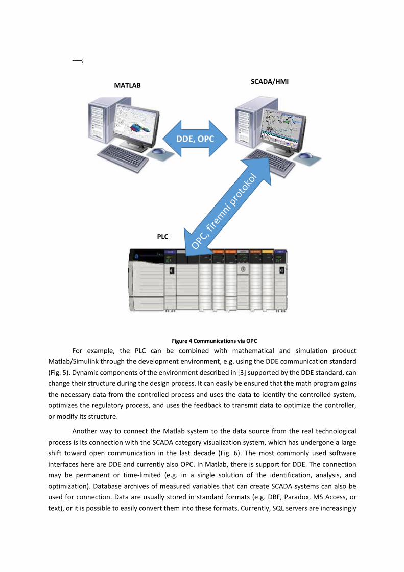
For example, the PLC can be combined with mathematical and simulation product
Matlab/Simulink through the development environment, e.g. using the DDE communication standard
(Fig. 5). Dynamic components of the environment described in [3] supported by the DDE standard, can
change their structure during the design process. It can easily be ensured that the math program gains
the necessary data from the controlled process and uses the data to identify the controlled system,
optimizes the regulatory process, and uses the feedback to transmit data to optimize the controller,
or modify its structure.
Another way to connect the Matlab system to the data source from the real technological
process is its connection with the SCADA category visualization system, which has undergone a large
shift toward open communication in the last decade (Fig. 6). The most commonly used software
interfaces here are DDE and currently also OPC. In Matlab, there is support for DDE. The connection
may be permanent or time-limited (e.g. in a single solution of the identification, analysis, and
optimization). Database archives of measured variables that can create SCADA systems can also be
used for connection. Data are usually stored in standard formats (e.g. DBF, Paradox, MS Access, or
text), or it is possible to easily convert them into these formats. Currently, SQL servers are increasingly
DDE, OPC
MATLAB SCADA/HMI
PLC
Figure 4 Communications via OPC
used, specialized (IndustrialSQL Server) and generally applicable (MS SQL Server, InterBase, MySQL,
PostgreeSQL in cases with lower requirements). It is possible to communicate with these databases
from Matlab using the instrument Database Toolbox via ODBC (Open Database Connectivity) or JDBC
(Joint Database Connectivity) software interface. The logical way to access source data through Matlab
from a real technological process is a direct connection to the physical topology of the data collection
system e.g. via the serial interface shown in Fig. 7. Thus, Matlab becomes one of the participants in the
communication with PLC. A serial communication object can be used for serial communication from
Matlab version 6.0.
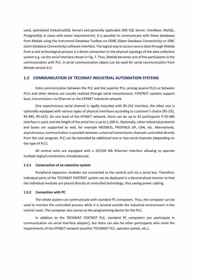
1.3 COMMUNICATION OF TECOMAT INDUSTRIAL AUTOMATION SYSTEMS
Data communication between the PLC and the superior PCs, among several PLCs or between
PLCs and other devices are usually realized through serial transmissions. FOXTROT systems support
basic transmissions via Ethernet or the EPSNET industrial network.
One asynchronous serial channel is rigidly mounted with RS-232 interface, the other one is
optionally equipped with various types of physical interfaces according to customer’s choice (RS-232,
RS-485, RS-422). On one level of the EPSNET network, there can be up to 32 participants if RS-485
interface is used, and the length of the serial line is up to 1,200 m. Optionally, other industrial protocols
and buses are supported as well, for example MODBUS, PROFIBUS DP, CAN, etc. Alternatively,
asynchronous communication is possible between universal transmission channels controlled directly
from the user program. PLC can be extended by additional one or two serial channels (depending on
the type of PLC).
All central units are equipped with a 10/100 Mb Ethernet interface allowing to operate
multiple logical connections simultaneously.
1.3.1 Construction of an extensive system
Peripheral expansion modules are connected to the central unit via a serial bus. Therefore,
individual parts of the TECOMAT FOXTROT system can be deployed in a decentralized manner so that
the individual modules are placed directly at controlled technology, thus saving power cabling.
1.3.2 Connection with PC
The whole system can communicate with standard PC computers. Thus, the computer can be
used to monitor the controlled process while it is located outside the industrial environment in the
control room. The computer also serves as the programming device for the PLC.
In addition to the TECOMAT FOXTROT PLC, standard PC computers can participate in
communication via serial interface adapter), but there can also be other participants who meet the
requirements of the EPSNET network (another TECOMAT PLC, operator panels, etc.).

1.3.3 Distributed Control Systems
These factors create prerequisites for the implementation of extensive systems of distributed
or hierarchical control. Such systems can also be established through “gradual steps from below” so
that the originally autonomous systems are gradually combined and complemented with the upper
level of control, or just with central monitoring and data collection.
The main advantage of distributed systems is the possibility of autonomous control even in the
case of the failure of the centre, gradual putting the entire system into operation, easier debugging,
complementing, cost and labour saving during installation (e.g. in cabling, switchboards).
1.3.4 Programming device
PC can be used as a programming device. Computer configuration must be selected according
to the requirements of software (Mosaic, Reliance, ...).
TECOMAT FOXTROT offers a number of useful system services that simplify programming and
make it more pleasant. An example might be a broad range of time data, published current date and
time, or system support to solve the states when PLC power supply is switched on.
Fieldbus Profibus.
Profibus is intended for automation of production lines, for domestic and process automation,
and for the production control and distribution of energy.
1.3.5 Basic features of Profibus
Profibus supports four topologies:
bus
tree
star
circle
The preferred topology is the bus.
Transmission speed [kbit/s] 9.6 19.2 93.75 187.5 500 1500 12000
Length [m] 1200 1200 1200 1000 400 200 100
1.3.6 Profibus DP (Decentralized Periphery)
This is the simplest and most widespread variant of Profibus, designed for fast communication
of the master-slave type. It is especially suitable for quick transmission of signals from the process by

means of decentralized peripherals and isolated I/O units. The communication medium is either a
twisted pair (standard RS-485) or optical fiber at the speed of up to 12 Mbit/s.
1.3.7 Profibus FMS (Fieldbus Message Specification)
It offers a communication standard for communication in a heterogeneous environment with
a large set of services for working with data, programs, and alarms. Similar to the variant Profubus DP,
the communication medium is either a twisted pair (standard RS-485) or optic fibre, but the speed is
now lower.
1.3.8 Profibus PA (Process Automation)
It uses extended standard Profibus DP and it is designed to control slow processes, especially
in explosive environments, since it corresponds to the intrinsic safety. To be able to use the network
in this environment, a special physical layer is used – a current loop in accordance with the standard
IEC 1158-2 communicating at the constant speed of 31.25 kbit/s.
Summary of Terms
Integration into higher units involves the existing PLCs communicating via the
Ethernet performance computing interface and within the Internet. Thus, the automated
operation or building can be incorporated into the global control and monitoring system.
This allows e.g. to control, monitor, and optimize the operation of large manufacturing
plants.
Communication and distributed intelligence means the ability to connect PLC to
networks and build create distributed systems, it also opens the way for realization of
parallel intelligent systems, whose parts (subsystems) may contribute to the realization of
the common algorithm.
Profibus is intended for automation of production lines, for domestic and process
automation, as well as for the production control and energy distribution. It supports any
topology, the bus is preferred. Transmission technology: includes RS485, optical fibre, and
a current loop. It includes buses:
Profibus DP (Decentralized Periphery),
Profibus FMS (Fieldbus Message Specification),
Profibus PA (Process Automation).

Questions
1. Describe and explain: Integration into higher units
2. Describe and explain: Communication and distributed intelligence
3. Could you describe and explain: Communication of Tecomat industrial controllers
4. Describe and explain: Creating an extensive system
5. Describe and explain: Connection with PC
6. Describe and explain: Distributed Control Systems
7. Describe and explain: Industrial Profibus
8. Describe and explain: Basic properties of Profibus

2 OPERATOR PANELS AND PROGRAMMING
Study time
30 minutes
Objective
After reading this paragraph, you will be able to define, describe:
Operations of control panels.
The operator panel mode in the slave mode.
The operator panel mode in the master mode.
Programming operation.
Lecture
Operator panels for communication between the operator and the machine. HMI operator
panels increase the functionality and clarity of management systems, make the equipment operation
easier, and enable to monitor and change parameters of the production technology or machines. Their
installation is simple, as these HMI units are installed directly into the machine, without requiring the
use of additional modules in the PLC. All necessary information is easily accessible to ensure maximum
transparency of all processes. Thanks to the high IP65 coverage (GOT1000 even IP67), these panels can
be deployed in the most demanding industrial environments.
Case studies, Solved example
We will use Teco operator panels as an example of programming and functions.
Operator panels ID-07 and ID-08 are designed for cooperation with TECOMAT and TECOREG
systems and are designed for assembly building.
The panel is powered from an external source SELV 24 V AC or 24 V DC. It has a membrane
keyboard with buttons with mechanical response and a backlit LCD display. The advantage of the
backlit display is good legibility both in daylight and in darkness.
In addition to standard ASCII characters, characters with diacritical marks can be displayed on
the display panel in the selected encoding. In one text, diacritical marks are limited to eight different
characters.
Communication between the master system and panels ID-07 and ID-08 is realized through a
standard serial line RS-232, RS-422, or RS-485. In the slave mode, the panel shows signs emitted by the

control system to the display, and as a response to the message with content of the display, it transmits
to the control system the keystroke code. In the master mode, it belongs to a group of active control
panels and it acts as a superior system to the PLC; it actively sends keystroke code and he reads the
display. The panel is connected to the communication channel of PLC system TECOREG or TECOMAT
in the PC mode.
When using interface RS-422, or RS-485, line must be impedance matching on both sides with
resistance of 120 Ω, and in some cases, it is necessary to connect the signal ground to balance their
potentials. Standard supplied cables to connect to NS-950 are already impedance matching in the
connector. For impedance matching on the side of panels ID-07, ID-08, termination resistors are
supplied as accessories.
Figure 5 Principle of connecting panels in the chain
Legenda: bílá – white; hnědá – brown; zelená – green; žlutá - yellow
2.1 OPERATION OF CONTROL PANELS
The format of the transmitted data has the following parameters:
1 START BIT 8 BITS DATA EVEN PARITY 1 STOP BIT

2.1.1 Operator panel in the slave mode
The text that we want to display it passed to the panel as one integral message composed of
ASCII character codes of the text (32 or 80 characters, depending on the panel). The message is
considered integral if the observed delay between characters is shorter than the transmit time of two
characters.
Another requirement is that the sum of all delays in one solid message must be less than the
time required to transmit ten characters. In any case, the length of the delay between messages when
communicating must correspond to the transmit time of a minimum of twenty characters at the given
communication speed.
2.1.2 Operator panel in the master mode
When communicating, the panel acts as a superior participant (master) and the PLC as a
subordinate participant (slave). The panel uses WANDRN service for communication (recording to
registers and reading the contents of registers of the PLC scratchpad memory) of EPSNET network (see
the manual Serial communication of programmable controllers TECOMAT TXV 001 06.01). Only one
operator panel can be connected to one PLC serial port. The panel sends messages to the slave system
in 100 ms raster.
2.2 PROGRAMMING OPERATION
The panels thus behave very much like conventional ASCII terminals. The difference lies in the
fact that a traditional ASCII terminal uses full duplex operation to communicate, i.e. information about
the pressed key is not subject to entry of characters into the terminal and is transmitted to the control
system at the time of keystroke. For panels ID-07, or ID-08, half duplex is used for communication, so
to test the keyboard state, all of the characters for the display must be first transmitted to the panel.
Therefore, it is necessary to transmit characters for the display in regular time raster, primarily to avoid
losing information about the pressed keys.
This apparent complication is balanced with possibilities that are not available in conventional
ASCII terminals because of the full duplex. Panels ID-07, or ID-08 can be connected behind each other
on a single serial line, so that the PLC transmitter will be connected to the receiver of the first panel,
its transmitter will be connected to the receiver of the second panel, and the transmitter of the second
panel will be connected back the to the receiver of the PLC. In this case, we transmit from the PLC the
contents of the first display as one data packet followed by data for the second display. The first
operational panel displays the first part of the data on the screen, and the characters that do not fit on
the screen, are sent to the second operating panel. At the end of these characters, it adds the state of
its own keyboard (i.e. the code of the last keystroke; if no key has been pressed, binary 0 is added).
Another terminal repeats the same procedure. The first portion of the received data are shown on the
display, and what does not fit to the display will be forwarded and the state of the keyboard will be
added at the end. The result is that key codes pressed in all terminals are received in the PLC as a
response to the transmitted content of displays. No addressing of terminals is required.

The described operating panels are not equipped with any “escape” sequences, as it is the case
with conventional ASCII terminals. Functions such as a flashing sign, scrolling text, etc. must be realized
by a change data transmitted to the panel. Because the data are transmitted to the panel periodically,
it is not a problem. On the other hand, the advantage is a very simple interface between the operating
panel and control system.
When programming the operation of the operating panel connected to the PLC TECOMAT, it
is appropriate to divide the problem into two tasks. The first one involves the preparation of a text to
be displayed on the operating panel and processing keys pressed by the panel operator. The second
task ensures the serial communication with the panel, i.e. periodic transmission of the prepared text
from the PLC registers on the display panel and receiving the code of the keystroke.
Panels in the slave mode must be connected to the serial channel control system, which is set
to the Uni mode. A detailed description of the scheme is given in the manual Serial communication of
programmable controllers TECOMAT TXV 001 06.01. In this case, the communication with the panel
must be operated by the control system user's program. Examples of programs for communication are
provided on the CD-ROM Teco-info. For the communication in the Uni mode, it is not possible to use
CH1 channel of any Tecomat or Tecoreg system, since this channel only works in the PC mode.
Furthermore, the serial channel CH2 at the central unit CPM-2B (NS950 series) cannot be used either
for the same reason. All other serial channels can be switched to the Uni mode and use them to
communicate with panels ID-07, or ID-08.
Summary of Terms
OPERATION OF OPERATOR PANELS takes place in the Master Mode or Slave Mode.
Operator panel in the slave mode is controlled from the superior PLC.
Operator panel in the master mode writes directly to the PLC registers.
PROGRAMMING THE OPERATION uses half-duplex bus operation. When programming
the operation of the operating panel connected to the PLC TECOMAT, it is appropriate to
divide the problem into two tasks. The first one involves the preparation of a text to be
displayed on the operating panel and processing keys pressed by the panel operator. The
second task ensures the serial communication with the panel, i.e. periodic transmission
of the prepared text from the PLC registers on the panel display and receiving the code of
the keystroke.

Questions
1. Describe and explain: Operation of control panels
2. Describe and explain: Operator panel in the slave mode
3. Describe and explain: Operator panel in the master mode
4. Describe and explain: Programming the operation
3 NETWORK COMMUNICATION. INDUSTRIAL
ETHERENET. IP ADDRESSES, DHCP SERVER.
Time to study
30 minutes
Objective
After reading this paragraph, you will be able to define, describe:
Network, DHCP server, IP communications, TCP/IP.
Set TCP/IP address, describe the physics of the Ethernet layer, the extended version IEEE
802.3, Ethernet network cables
Lecture
Ethernet is a physical and data layer technology for local area networks (LAN). Ethernet was
invented by an engineer Robert Metcalfe. It was first widely deployed in 1980. Ethernet supports a
maximum theoretical transfer rate of 10 megabits per second (Mbps). Later, the so-called “Fast
Ethernet” standards increased the maximum data transfer rate up to 100 Mbps. Today, Gigabit
Ethernet technology extends the peak performance up to 1000 Mbps. Currently, the transmission is
realized by the twisted pair or the Profibus communication line.
Higher level of network protocols such as IP (Internet Protocol) use Ethernet as the
transmission medium. Data are transmitted in the Ethernet network.
The length of each Ethernet cable is limited to about 100 meters, but the Ethernet network
can be easily extended to link entire buildings or larger industrial volumes using active network
elements, such as switch.
Ethernet and its network interface (or network cards) only work with so-called “Ethernet
frameworks”. Common network protocols (e.g. currently the most widely used TCP/IP protocol) are
transmitted in the data part of Ethernet frameworks, and the network card itself does not understand
them. In a computer, the network card is operated by the driver that is part of the core operating
system. Higher protocols (e.g. the above-mentioned TCP/IP) are typically handled within the core
operating system.

3.1 IP COMMUNICATION
The Internet Protocol (IP protocol) is the basic protocol of the network layer and the entire
Internet. It transmits datagrams based on network IP addresses contained in its header. It provides
higher layers with network service without the connection. Each datagram is an independent unit of
data that contains all the necessary information about the recipient and the sender and the serial
number of the datagram in the report. Datagrams travel through the network independently of each
other and the order of their receipt may not match the order in the report. Datagram delivery is not
guaranteed, the reliability must be ensured by higher layers (TCP, applications).
The report also takes care of segmentation and re-assembly of datagrams to and from the
frameworks by the lower layer protocol (e.g. Ethernet).
Currently, mainly the protocol of IP version 4 is used. A new version 6 is prepared, which
addresses the shortage of addresses in IPv4 and security issues, and improves other properties of IP
protocol.
3.2 PROTOCOL TCP/IP
TCP/IP protocol contains a set of protocols for communication in the PC network, and it is the
main protocol of the global Internet network. The communication protocol is a set of rules that define
the syntax (a sequence of individual characters and operations) and the importance of individual
messages in the communication.
Given the complexity of problems, network communication is divided into so called layers that
show the hierarchy of activities. The exchange of information between layers is clearly defined. Each
layer uses the services of the layer below and provides its services to a higher layer. The whole meaning
of the word TCP/IP is Transmission Control Protocol/Internet Protocol (Czech primary transport
protocol - TCP/network layer protocol - IP).
With the development of modern technology, it has proved very advantageous to equip the
programmable controllers with an interface for communication via TCP/IP. A controller equipped with
this interface can share information with many other controllers equipped with this interface, as well
as with other devices that have this interface. TCP/IP is the universal protocol, so the distance does
not mean limitation when communicating, but if necessary, it is possible to communicate via the
Internet, for example from one continent to another.
Solved example

3.3 SAMPLE SETTING TCP / IP ADDRESS
First, you need to insert TCP/IP driver into the project. This is done in the Driver Configuration,
the Insert Driver and the TCP/IP driver is selected. The following window appears where you set some
important data:
Figure 6 Configuration Window for module EtherNet/IP
For proper function of all units in a network, you only need to set the value of the IP addresses.
This address consists of four numbers from 0 to 255, and each computer or controller must have a
different address. In our case, 192.168.1.10, another one can have, e.g. 192.168.1.11. The important
part is the subnet mask that specifies which part of the address is reserved for each unit. For correct
communication, there must be the same subnet address for all units, here, for example, 192.168.1.xxx.
After setting the address, click OK, and we have configured the card, so we can take advantage
of the computer network.

Figure 7 SoftLogix system with an embedded Ethernet card
In the picture SoftLogix system with embedded Ethernet communications card, we can see the
card in position 2 in the top row. However, the basic communication with program RSLogix 5000 is
provided by implicitly installed modules; RSLinx card is at the position 0.
The communication between the same layers of two different systems is controlled by the
communication protocol using the connection established by the adjacent lower layer. The
architecture enables to exchange protocols of one layer without affecting the others. An example could
be the ability to communicate over different physical media - Ethernet, optical fibre, serial line.
Continuation of the lecture
TCP/IP architecture is divided into four layers:
• application layer
• transport layer
• network layer
• network interface layer

Figure 9 The TCP / IP
Legenda: Architektura TCP/IP – TCP/IP architecture; aplikační – application; transportní –
transport; síťová – network; síťové rozhraní – network interface
3.3.1 The Ethernet physical layer
This section applies in particular to different standards according to IEEE 802.3. The original
ones were moving at the speed of 10Mbit/s, and they include these:
10Base2 - (Rate Basic Band Length) length up to 185 m, up to 30 guests per segment
10Base5 – up to 500m, up to 1024 guests/segment
10BaseT – 1 guest per a segment or cable
3.3.2 Extended versions IEEE 802.3:
100BaseTX (IEEE 802.3u) – 100Mbit/s, UTP cable class 5 to 7, 1 guest per cable/segment, up
to 100m
100BaseFX (IEEE 802.3u) – up to 412, optics, two-point connection
1000BaseCX (IEEE 802.3z) – 1Gb/s, “twinax” (coax), up to 25m
1000BaseT (IEEE 802.3ab) – UTP class 5 (4 pairs), up to 100m
Solved example

3.4 IP ADDRESS ASSIGNMENT IN THE INDUSTRIAL ETHERNET
IP address assignment in the Industrial Ethernet must follow the same rules as in the case of
the conventional network. Each device must have its unique address provided that the device on one
subnet has the same common part of the address belonging to the subnet.
In the case of Rockwell PLC CompactLogix and ControlLogix, in principle, three ways of
assigning addresses, each of which has its advantages and disadvantages. The options are:
Fixed IP address,
Address assigned by the DHCP server,
Address assigned via BootP, or bootstrap protocol.
3.4.1 Fixed IP address.
Fixed IP address is the simplest way to assign the address to the communication module. The
disadvantage is the need to reconfigure the address if the communication card or processor or other
devices, e.g. the frequency converter that contains the Ethernet communication port is replaced. The
example of address assignment was shown in the previous text.
3.4.2 DHCP server
DHCP is used to assign IP addresses based on the physical MAC addresses of the device.
Dynamic Host Configuration Protocol (DHCP) uses the DHCP server that must be available in the
network. Once the device is connected to the network, it will request that the DHCP server
automatically assigns IP address, subnet mask, DNS servers, gateway addresses, and so on. The IP
address is dynamic, so the device can receive a different IP address every time it is connected to the
network.
3.4.3 Bootstrap protocol
Bootstrap Protocol (BootP) assigns the same IP address every time it connects to the network.
Its server has a list of hardware addresses and IP addresses that belong to each device. When a device
(such as PLC) is connected to the network unless it has been assigned an address, it is configured that
it is supposed to obtain an IP address using BootP, and it will broadcast a request for address
assignment. BootP server then finds hardware address in the list, and finds out which IP address
belongs to the respective PLC. It then returns the IP address (and other information, such as subnet
mask, to be used) to it.
Summary of Terms
TCP/IP architecture is divided into four layers:

• application layer
• transport layer
• network layer
• network interface layer
IP address assignment in the Industrial Ethernet must follow the same rules as in
the case of the conventional network. Each device must have its unique address provided
that the device on one subnet has the same common part of the address belonging to the
subnet.
In the case of Rockwell PLC CompactLogix and ControlLogix, in principle, three
ways of assigning addresses, each of which has its advantages and disadvantages. The
options are:
• Fixed IP address,
• Address assigned by the DHCP server,
• Address assigned via BootP, or bootstrap protocol.
DHCP is used to assign IP addresses based on the physical MAC addresses of the
device. Dynamic Host Configuration.
Bootstrap Protocol (BootP) assigns the same IP address every time it connects to
the network. Its server has a list of hardware addresses and IP addresses that belong to
each device.
Qustions
1. Describe and explain: Network communication. Industrial Etherenet. IP addresses,
DHCP server.
2. Describe and explain: IP Communications.

4 CHECKING CONTINUOUS PROCESSES.
Time to study
4 hours
Objective
Define, describe: Analog inputs, Analog outputs
Lecture
This chapter describes how to work with analog signals and how they are used, and it will
describe the function of the composite analog I/O 1769-IF4XOF2 module.
It includes the following information:
• how to use the analog I/O card
• a general description of hardware modules and module diagnostics
• overview of the analog system
The analog (continuous) value represents the value of continuous physical quantity. First, the
physical quantity is measured by a suitable sensor and subsequently transferred to the measurable
signal. This signal is then brought to the control system input, here PLC. This following application
shows a typical use of analog data in the process control.
In this application, PLC uses the valve position to regulate the amount of fluid in the reservoir.
The valve is initially opened to 100%. As the fluid level in the reservoir approaches the required value,
PLC modifies the value output, half-shutting the valve to 90%, 80%, etc., changing the valve position
maintains the required liquid level in the tank.
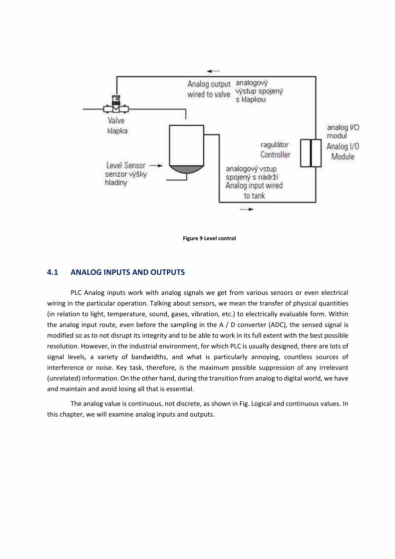
Figure 9 Level control
4.1 ANALOG INPUTS AND OUTPUTS
PLC Analog inputs work with analog signals we get from various sensors or even electrical
wiring in the particular operation. Talking about sensors, we mean the transfer of physical quantities
(in relation to light, temperature, sound, gases, vibration, etc.) to electrically evaluable form. Within
the analog input route, even before the sampling in the A / D converter (ADC), the sensed signal is
modified so as to not disrupt its integrity and to be able to work in its full extent with the best possible
resolution. However, in the industrial environment, for which PLC is usually designed, there are lots of
signal levels, a variety of bandwidths, and what is particularly annoying, countless sources of
interference or noise. Key task, therefore, is the maximum possible suppression of any irrelevant
(unrelated) information. On the other hand, during the transition from analog to digital world, we have
and maintain and avoid losing all that is essential.
The analog value is continuous, not discrete, as shown in Fig. Logical and continuous values. In
this chapter, we will examine analog inputs and outputs.

Figure 10 Logical and continuous values
Typical analog inputs and outputs for the PLC are shown below. Actuators and sensors that can
be used with analog inputs and outputs are discussed in the following chapters.
Inputs:
furnace temperature;
fluid pressure;
liquid flow.
Outputs:
valve position indicating fluid flow;
engine location;
engine speed.
4.2 ANALOG INPUTS
This chapter focuses on the general principles of digital-to-analog (D/A) and analog-to-digital
(A / D) converter.
Analog voltage applied to the input (to a PLC or another computer) is continuous value; this
continuous values must be sampled, and the samples have to be converted to a numeric value through
the A / D converter. Figure Sampling analog voltage indicates the voltage in time. Three samples shown
in the figure were taken. The data sampling process is not instantaneous, so each sample has its time
when sampling starts and when it is completed. The time required to obtain a sample is called the
sampling time. A / D converters can process only a limited number of samples per second. T time
between samples is called the sampling period and the reciprocal of the sampling period is the
sampling rate. The sampling time is often much shorter than the sampling period. For PLC values, the
maximum sampling rate can reach up to 20Hz.
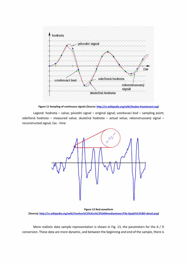
Figure 11 Sampling of continuous signals [Source: http://cs.wikipedia.org/wiki/Soubor:Kvantovani.svg]
Legend: hodnota – value; původní signal – original signal; vzorkovací bod – sampling point;
odečtená hodnota – measured value; skutečná hodnota – actual velue; rekonstruovaný signal –
reconstructed signal; čas - time
Figure 12 Real waveform
[Sourcej: http://cs.wikipedia.org/wiki/Vzorkov%C3%A1n%C3%AD#mediaviewer/File:Spojit%C3%BD-detail.png]
More realistic data sample representation is shown in Fig. 13, the parameters for the A / D
conversion. These data are more dynamic, and between the beginning and end of the sample, there is
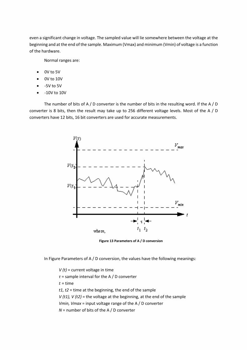
even a significant change in voltage. The sampled value will lie somewhere between the voltage at the
beginning and at the end of the sample. Maximum (Vmax) and minimum (Vmin) of voltage is a function
of the hardware.
Normal ranges are:
0V to 5V
0V to 10V
-5V to 5V
-10V to 10V
The number of bits of A / D converter is the number of bits in the resulting word. If the A / D
converter is 8 bits, then the result may take up to 256 different voltage levels. Most of the A / D
converters have 12 bits, 16 bit converters are used for accurate measurements.
Figure 13 Parameters of A / D conversion
In Figure Parameters of A / D conversion, the values have the following meanings:
V (t) = current voltage in time
τ = sample interval for the A / D converter
𝑡 = time
t1, t2 = time at the beginning, the end of the sample
V (t1), V (t2) = the voltage at the beginning, at the end of the sample
Vmin, Vmax = input voltage range of the A / D converter
N = number of bits of the A / D converter

If voltage changes too rapidly during the sampling, we can obtain false values, as shown in
Figure Aliasing at a low sampling rate. The top of the chart shows the course after completion of seven
periods when 9 samples were taken. The lower chart represents the measured values. The sampling
rate is too low, so the reconstructed signal is different than it is in reality; this phenomenon is called
aliasing.
.
Nyquist criterion states that the sampling rate must be at least twice the frequency of the
signal being measured, otherwise aliasing occurs. If this happens in real applications, the system will
obviously work incorrectly. In practice, the sampling frequency should be four or more times higher
than the highest frequency in the sampled signal.
4.3 ANALOG INPUT PARAMETERS
The most important parameters of analog inputs include their number, resolution, maximum
sampling frequency, and voltage ranges. Although the resolution is in principle determined by the used
A / D converter, other included circuits may improve or worsen the final properties of the card by
several classes. It is therefore not appropriate to focus only on a single number, but it is necessary to
get thoroughly familiar with all the details regarding the accuracy of the card. While in the case of
cheap cards, the manufacturer specifies only the number of bits or a simple characteristic such as
“accuracy better than 1%, INL < 1.5 LSB”, documentation for quality cards usually also contains the
ingredients of error (offset, error of the data, and noise for each range), and often their temperature
dependence is included as well. If the card is to be used to actually binding measurement, surely it
would be desirable to acquire its calibration certificate, an indication of its validity period, and
information on the implementation of additional calibration. Thanks to falling prices of A / D converters
with higher resolution, currently there is a trend towards transition from eight-bit and twelve-bit cards
Figure 14 Aliasing at a low sampling rate

to sixteen-bit cards. Now it is possible to come across less resolution only in the fastest (oscilloscopic)
cards.
Risk of complications can also be hidden in the data of the maximum sampling rate. The
maximum speed of A / D converter is often stated, but especially cheaper cards switch all of their
inputs to a single converter. If such a card has a converter with a maximum sampling rate of 200 kHz,
when measuring only ten channels, only 20,000 samples per second are obtained on each of them.
Additionally, the measured quantities in each channel will be delayed for at least 5 seconds. Cards with
full measurement chain (input amplifier and A / D converter) for each channel do not have these
shortcomings, but they are considerably more expensive. Some cards tend to have the input filter of
the low-pass filter type that prevents violation of the sampling theorem, and prevents distortion of the
frequency spectrum of the signal (anti-aliasing). Together with the maximum sampling rate, it is also
appropriate to identify even a step or a way of creating lower frequencies, or the possibility of stepping
by external signal, because cards that use a frequency divider are not able to create any sampling rate
(e.g. 44.1 kHz, often required in acoustics).
For voltage ranges, it is necessary to check not only whether the measured signal does not
exceed the possibilities of the card, but also whether its measuring range will be well utilized. While
some cards have eight or more software-switchable ranges, other cards have only one range. If the
signal is to be measured in the range 0-2 V, the card with selectable unipolar range of 0 to 2.5 V should
certainly get the priority before the card with a single range of ± 10 V. With the same resolution of A /
D converter, the first card will result in eight times smaller quantization noise. In addition to voltage
ranges, the level of protection of the card inputs against overvoltage is also an important indicator.
4.4 ANALOG OUTPUTS
Analog outputs - using these outputs, it is possible to control continuous servo drives and
frequency converters, as well as dial gauges and other continuous actuators.
Analog outputs are expected to enable remote control of the relevant activities and functions.
They can be part of the complex loop in PLC or PID (proportional-integral-derivative) control loop, or
only perform basic, simple functions such as turning on / off, lighting, or ventilation. In most cases, the
necessary commands will be ensured by a microprocessor. The block of analog outputs evaluates them
and converts them into a suitable form of analog or logic signals, which then controls motors, valves,
relays, etc. With considerable contribution of D / A converter (DAC) and other support circuitry for
processing the signal, the digital image of the CPU can be reconverted into default analog world
(voltage or current). Therefore, at each output we have “tailor-made” signals at our disposal. There
are also other possible “wrinkles” in the form of calibration.
The current output of the D / A converter is usually limited to a small value, typically less than
20 mA. This is enough for instrumentation, but for high current loads, such as motors, it is necessary
to use a current amplifier.

The basic principle of the D / A converter is shown in Figure D / A converter with resistor
network
The disadvantage of the converter with a weight network is that its realization needs resistors
having large dispersion values (for the 12-bit converter, the ratio of the largest and smallest resistor is
2048: 1, and their accuracy ratio must be the same. Therefore, a transmitter with a resistor ladder (or
tie) network is used. The wiring diagram is shown in Figure D / A converter with a resistor ladder
network.
Figure 15 D / A converter with a resistor network
Legend: analogový výstup – analog output
Figure 16 D / A converter with a resistor ladder network

Summary of Terms
The analog (continuous) value represents the value of continuous physical
quantity. First, the physical quantity is measured by a suitable sensor and subsequently
transferred to the measurable signal. This signal is then brought to the control system
input, here PLC. This following application shows a typical use of analog data in the process
control.
Within the analog input route, even before the sampling in the A / D converter
(ADC), the sensed signal is modified so as to not disrupt its integrity and to be able to work
in its full extent with the best possible resolution. However, in the industrial environment,
for which PLC is usually designed, there are lots of signal levels, a variety of bandwidths,
and what is particularly annoying, countless sources of interference or noise. Key task,
therefore, is the maximum possible suppression of any irrelevant (unrelated) information.
On the other hand, during the transition from analog to digital world, we have and
maintain and avoid losing all that is essential.
The data sampling process is not instantaneous. The time required to obtain a
sample is called the sampling time. A / D converters can process only a limited number of
samples per second. T time between samples is called the sampling period and the
reciprocal of the sampling period, the sampling rate
Normal ranges are:
0V to 5V
0V to 10V
-5V to 5V
-10V to 10V
The number of bits of the A / D converter is the number of bits in the resulting
word
If voltage changes too rapidly during the sampling, we can obtain false values -
aliasing.
Nyquist criterion states that the sampling rate must be at least twice the frequency
of the signal being measured, otherwise aliasing occurs.
Converting the analog measured signal to digital takes place in specially developed
PLC cards. The basic types of transducers include comparator, chain, compensation,
surveillance, successive approximation, integration with single and double integration
transducers.

The basic connection of analog input card contains converters that are electrically
isolated from the PLC internal bus. It contains its own microprocessor, which controls the
further processing of transferred values.
Due to, e.g. interference or displacement of the potential of the sensor against
measurement zero, PCL can connect the signal to a pair of inputs instead of a simple
analog input; in this case, this pair of inputs has the function of the differential amplifier.
The current signal is connected in conformity with the connection shown in Figure
Connecting the current signal.
Cards of thermocouple inputs include extra temperature compensation circuitry
for cold junction of thermocouples
Three-wire resistive sensor connection compensates the voltage drop across
resistive sensor power lines.
Analog outputs - these outputs can be used to control and continuous servo drives
and frequency converters, but they also include dial gauges and other continuous
actuators.
The basic principle of the D/A uses a resistor network
A disadvantage of a transducer with a weight network is that its realization needs
resistors with large variance of values. Therefore, a converter with a ladder (or tie) resistor
network is used.
Questions
1. Describe and explain: Analog inputs
2. Describe and explain: Analogue outputs
3. The principles of the analog-digital conversion.
4. The principles of the digital-analog conversion.
5. Describe and explain: Parameters of analog inputs
6. Describe and explain: A / D converter
7. Describe and explain: The principle and description of analog outputs
8. Describe and explain: The description of the module of the combined analog input-
output card

5 CONTROLNET
Time to study
40 minutes
Objective
After reading this paragraph, you will be able to describe and apply:
ControlNet – data network.
Technology Producer - Consumer.
ControlNet specifications.
The topology of the network. The network capacity.
Lecture
ControlNet of the company Rockwell Automation (Allen Bradley) is a new-generation of a data
network for automation and control. It is a powerful network with a transmission rate of 5 Mbit/s,
enabling to send time-critical data in a deterministic and repeatable way. A change in the number of
connected devices does not affect the operation of the network. ControlNet allows you to specify a
point in time to send data (determinism), and this point in time does not change if the devices are
connected or disconnected from the network (repeatability).
ControlNet has a patented method of access that supports deterministic transfer of time-
critical input/output data. Other data, e.g. programming commands are also supported, and they are
assigned a lower priority. Therefore they cannot disrupt the transmission of time-critical data. In
addition, ControlNet allows the user to individually adjust the data transfer rate of individual nodes or
input/output modules.
ControlNet uses advanced network model called producer/consumer.
In this model, each node can be a sender (producer), recipient (consumer), or both. Time-
critical data are transmitted deterministically through high-speed connection, while other data are
transmitted via the client-server connection. The strong point of this network is the possibility of
multiple approaches at the same time. For example, the possibility of multiple nodes to receive data
sent by one node simultaneously. This method is much more efficient than the old token-pass or
master-slave models.
Advantages of ControlNet:

installation flexibility
backup option
equal access to the network from each node
one connection for transferring input/output data, programming
Improved peer-to-peer communication
user selectable frequency of input/output transmission
determinism/repeatability
simplified access to analog data
high refresh rate
improved system diagnostics
5.1 TECHNOLOGY PRODUCER - CONSUMER
ControlNet uses a network model called producer-consumer. In this model, each node can be
a sender (producer), recipient (consumer), or both. Time-critical data are transmitted deterministically
through high-speed connection, while other data are transmitted via the connection client-server. The
strong point of this network is the ability to implement multiple accesses at one time. For example, it
is possible that several nodes simultaneously accepted data sent by one node. This method is more
effective than earlier methods of network management, such as e.g. token - pass or master - slave.
5.2 TECHNICAL SPECIFICATION
The transmission rate is 5 Mb/s. The maximum number of stations on the network is 99. These
connections can be via Allen-Bradley splitters, which may be located anywhere on the network
segment. The segment length depends on the number of connected nodes, and segments can be
connected via repeaters into larger networks. As the transmission medium, RG6 coaxial cable (cost-
effective, available, resistant to interference, with the proper width of the transmitted bandwidth) and
BNC connectors or fibre optic cable repeater are used. The segment length using the optical fibre can
be up to 10 km.
ControlNet network and all other devices on the network are configured using RSNetWorx for
ControlNet. Connecting to the network can be through the module 1770 - KFC, which is equipped with
serial communication RS - 232, or via a PCMCIA 1784 - PCC card, or PCI 1784 – PCIC card.
5.3 NETWORK TOPOLOGY
ControlNet network supports multiple topologies, including the main line/ connection cable,
star, tree, and ring structures. In its simplest form, ControlNet network represents backbone lines, to
which nodes using branches and 1 meter long connecting lines are connected, as shown in Figure 3.
To create other topologies, repeaters are required as shown in Figure 4 (star) and Figure 5 (ring).

Figure 17 Example of the topology main line/connected line of the ControlNet system
Legend: páteřní vedení – backbone lines; odbočka s 1 m připojovacím vedením – branch with
1-metre connecting line; uzel - node
Figure 19 Example of a star topology of the ControlNet system
Legend: opakovač - repeater

Figure 19 Example a ring topology of the ControlNet system
Legend: optický kabel – optical cable, optický nebo koaxiální kabel – optical or coaxial cable
Summary of Terms
ControlNet of the company Rockwell Automation (Allen Bradley) is network for
with a transmission rate of 5 Mbit/s, enabling to send time-critical data in a deterministic
and repeatable way. A change in the number of connected devices does not affect the
operation of the network. ControlNet allows you to specify a point in time to send data
(determinism), and this point in time does not change if the devices are connected or
disconnected from the network (repeatability).
ControlNet uses the advanced producer/consumer. In this model, each node can
be a sender (producer), recipient (consumer), or both.
In determining the capacity of the ControlNet network, among other things, the
number of available connections should be considered. Interconnection is a measure of
the number of devices with which the programmable controller or communication card
communicates. The connection establishes a communication link between two devices.
These connections can be:
programmable logic controller to local I/O modules or local communication
modules

programmable logic controller to remote I/O modules or remote communication
modules
programmable logic controller to remote I/O (optimized for rack construction)
modules
developed and adopted symptoms (tags)
reports
The number of connections used by the programmable controller is determined
indirectly by configuring the controller to communicate with other devices in the system.
Scheduled connections are unique for the ControlNet network.
The ControlNet network also uses unscheduled connections. An unscheduled
connection is a message transfer between programmable controllers or input/output,
which is started by the program with the MSG instruction. Unscheduled communication
via messages will enable to send and receive data when needed.
Questions
1. Describe and explain: ControlNet - Data network
2. Describe and explain: Technology producer - consumer
3. Describe and explain: Specifications
4. Describe and explain: Network topology
5. Describe and explain: Network capacity

6 DEVICE NET BUS
Time to study
40 minutes
Objective
Define and describe: Device Net. bus, Structure of the communication according to the OSI
model,
Advantages of DeviceNet, Communication modules for PC for DeviceNet network, DeviceNet
system with a strong cable, DeviceNet system with a weak cable, DeviceNet system with a flat cable,
DeviceNet network Configuration, DeviceNet typical configuration
Lecture
Today, DeviceNet bus belongs among the most widely used buses, and it is a part of the most
known PLC and PAC systems. It is characterized by a bus power supply, switchable data transfer speed
of up to 500 kB/s, and unusual communication model provider/customer. It provides high data
throughput within the network.
DeviceNet is a digital, multibus network, which primarily serves as a communication network
between industrial control systems (PLC, PAC, Embedded PC) and other I/O devices. Each connected
device in the network can be called one node, and the communication hierarchy is based on the OSI
model (Open Systems Interconnection model). DeviceNet communication is based on a unique
principle provider/recipient, allowing support for many communication hierarchies and broad
prioritizing of communication and data transfer between devices. The network can be configured for
the communication using the master-slave style, or as a distributed control architecture
communicating by means of the direct peer-to-peer style. The advantage is the possibility of power
supply of the units directly on the bus. The DeviceNet communication standard uses the CAN
(Controller Area Network) standard for its purpose at the level of the 2nd layer (line) of the OSI model
and the CIP™ (Common Industrial Protocol) standard for the 5th and higher layers of the OSI model.
6.1 KEY FEATURES
Characteristic features of the standard configurations can be summarized as follows:
Data transmission with selectable speeds of 125, 250, or 500 kb/s

Optional maximum size of the network (end-to-end network distance) in the range from 100
to 500 m
Choice between galvanically isolated or non-isolated physical interface
Possibility of power supply of the units on the bus
Data packets with an optional length of 0-8 bits
Protocol for creating frameworks from larger blocks of data
Multi-Master and Master-slave or peer-to-peer with the possibility of Multi-Cast
transmission communication
Using the CAN standard on the 2nd layer 2 of the OSI model
Using the CIP standard on the 5th and higher layers
6.2 COMMUNICATION STRUCTURE ACCORDING TO THE OSI MODEL
The model of the communication is based on the RM-OSI (Open Systems Interconnection
Reference) model due to application of multiple communication standards.
DeviceNet is a standard, open network accessible to all manufacturers of automation
technology for connecting to a system that allows data transmission at the lowest level of control –
sensors and actuators. Manufacturers of automation technology do not have to buy hardware and
software or licensing rights to connect to the control system.
DeviceNet is based on the communication protocol Controller Area Network (CAN), which was
originally developed for the European automotive industry. CAN network has high noise immunity and
integrated circuits are available from many manufacturers in the world (Philips, Motorola, Intel, NEC,
Siemens, etc.) DeviceNet was designed by the Allen-Bradley Company, and it is currently used by
almost one hundred companies producing sensors and actuators members.
Using DeviceNet enables cost-effective solution for connecting various devices to the network
access to smart devices from multiple vendors
Master/Slave and Peer-to-Peer communication skills
6.3 ADVANTAGES OF THE DEVICENET NETWORK
Interchangeability of devices from different manufacturers that will be compatible with
DeviceNet (buttons, starters, motors, photocells, limit switches) can be easily combined.
One common network with a standard open network will be able to find a common solution
for the end user quickly.
The tried DeviceNet standard is based and tested on known technology Controller Area
Network (CAN), which guarantees high reliability of the network.
Higher productivity, the possibility of easy diagnosis, and the possibility of replacing the
defective device in operation reduces the controlled technology downtime.

Cost reduction due to replacing conventional assembly of field devices by connecting to the
network saves installation costs.
The Open DeviceNet network is designed to allow two basic functions needed for simple
intelligent devices:
transmission of data in real-time oriented to control using I/O messages;
transmission of lower priority information, such as parameters of device configuration and
debbugging data, using Explicit messages.
Summary of terms
Today, DeviceNet bus belongs among the most widely used buses, and it is a part of the most
known PLC and PAC systems. It is characterized by a bus power supply, switchable data transfer speed
of up to 500 kB/s, and unusual communication model provider/customer. It provides high data
throughput within the network.
DeviceNet is a digital, multibus network, which primarily serves as a communication network
between industrial control systems (PLC, PAC, Embedded PC) and other I/O devices. Each connected
device in the network can be called one node, and the communication hierarchy is based on the OSI
model (Open Systems Interconnection model).
The model of the communication is based on the RM-OSI (Open Systems Interconnection
Reference) model.
DeviceNet is a standard, open network accessible to all manufacturers of automation
technology for connecting to a system that allows data transmission at the lowest level of control –
sensors and actuators. Manufacturers of automation technology do not have to buy hardware and
software or licensing rights to connect to the control system.
DeviceNet is based on the communication protocol Controller Area Network (CAN), which was
originally developed for the European automotive industry. CAN network has high noise immunity and
integrated circuits are available from many manufacturers in the world (Philips, Motorola, Intel, NEC,
Siemens, etc.) DeviceNet was designed by the Allen-Bradley Company, and it is currently used by
almost one hundred companies producing sensors and actuators members.

Questions
1. Describe and explain: Device Net Bus
2. Describe and explain: Structure of communication according to the OSI model
3. Describe and explain: Advantages of DeviceNet
4. Describe and explain: Communication modules for PCs in the DeviceNet network
5. Describe and explain: DeviceNet system with a strong cable
6. Describe and explain: DeviceNet cable system with a weak cable
7. Describe and explain: DeviceNet system with a flat cable
8. Describe and explain: DeviceNet network configuration
9. Describe and explain: DeviceNet typical configuration
References
[1] ROCKWELL AUTOMATION. 1769 Compact I/O Modules Specifications. USA: Rockwell
Automation, Inc., 2013. ISBN 1769-TD006D-EN-P. Dostupné z:
http://literature.rockwellautomation.com/idc/groups/literature/documents/td/1769-
td006_-en-p.pdf
[2] ROCKWELL AUTOMATION. ControlLogix Analog I/O Modules. USA: Rockwell Automation,
Inc., 2010. ISBN 1756-UM005B-EN-P. Dostupné z:
http://literature.rockwellautomation.com/idc/groups/literature/documents/um/1756-
um009_-en-p.pdf
[3] ROCKWELL AUTOMATION. ControlLogix Digital I/O Modules. USA: Rockwell Automation,
Inc., 2012. ISBN 1756-UM058G-EN-P. Dostupné z:
http://literature.rockwellautomation.com/idc/groups/literature/documents/um/1756-
um058_-en-p.pdf
[4] ROCKWELL AUTOMATION. ControlLogix High-speed Analog I/O Module. USA: Rockwell
Automation, Inc., 2010. ISBN 1756-UM005B-EN-P. Dostupné z:
http://literature.rockwellautomation.com/idc/groups/literature/documents/rm/1756-
rm003_-en-p.pdf
[5] ROCKWELL AUTOMATION. ControlLogix System. USA: Rockwell Automation, Inc., 2014.
ISBN 1756-UM001O-EN-P. Dostupné z:
http://literature.rockwellautomation.com/idc/groups/literature/documents/um/1756-
um001_-en-p.pdf
[6] ROCKWELL AUTOMATION. ControlNet Network Configuration. USA: Rockwell
Automation, Inc., 2011. ISBN CNET-UM001D-EN-P. Dostupné z:

http://literature.rockwellautomation.com/idc/groups/literature/documents/um/cnet-
um001_-en-p.pdf
[7] ROCKWELL AUTOMATION. DeviceNet Network Configuration. USA: Rockwell Automation,
Inc., 2011. DNET-UM004B-EN-P. Dostupné z:
http://literature.rockwellautomation.com/idc/groups/literature/documents/um/dnet-
um004_-en-p.pdf
[8] ROCKWELL AUTOMATION. EtherNet/IP Network Configuration. USA: Rockwell
Automation, Inc., 2013. ISBN ENET-UM001M-EN-P. Dostupné z:
http://literature.rockwellautomation.com/idc/groups/literature/documents/um/enet-
um001_-en-p.pdf
[9] ROCKWELL AUTOMATION. Logix 5000 Produced and Consumed Tags. USA: Rockwell
Automation, Inc., 2014. ISBN 1756-PM011F-EN-P. Dostupné z:
http://literature.rockwellautomation.com/idc/groups/literature/documents/pm/1756-
pm011_-en-p.pdf
[10] ROCKWELL AUTOMATION. Logix5000 Controllers Function Block Diagram. USA: Rockwell
Automation, Inc., 2014.ISBN 1756-PM009E-EN-P-. Dostupné z:
http://literature.rockwellautomation.com/idc/groups/literature/documents/pm/1756-
pm009_-en-p.pdf
[11] ROCKWELL AUTOMATION. Logix5000 Controllers General Instructions Reference Manual.
USA: Rockwell Automation, Inc., 2014. 1756-RM003P-EN-P. Dostupné z:
http://literature.rockwellautomation.com/idc/groups/literature/documents/rm/1756-
rm003_-en-p.pdf
[12] ROCKWELL AUTOMATION. Logix5000 Controllers I/O and Tag Data. USA: Rockwell
Automation, Inc., 2014. ISBN 1756-PM004E-EN-P. Dostupné z:
http://literature.rockwellautomation.com/idc/groups/literature/documents/pm/1756-
pm004_-en-p.pdf
[13] BOLTON, W. Programmable logic controllers. 4th ed. Amsterdam: Newnes, 2006. ISBN
978-075-0681-124.
[14] CHARRIA, Orlando. Fundamentals of programmable logic controllers and ladder logic. First
edition. 2010. ISBN 06-158-0007-6.
[15] HUGH, J. ROCKWELL AUTOMATION. Automating Manufacturing Systems with PLCs.
mikroElektronika, 2008. ISBN 0557344255. Dostupné z:
http://www.mikroe.com/old/books/plcbook/plcbook.htm
[16] PETRUZELLA, F.D., HACKWORTH,F.D. Programmable Logic Controllers: programming
methods and applications. 4th ed. New York: McGraw-Hill Companies,Inc., 2010, 396 s.
ISBN 00-735-1088-2.
[17] HAS®. Programovatelné automaty TECOMAT FOXTROT CP-1004. Kolín: Teco a. s, 2014.
ISBN TXV 004 34.01. Dostupné z:
http://www.tecomat.com/wpimages/other/DOCS/cze/TXV00434_01_Foxtrot_CP_1004.p
df

[18] OPERÁTORSKÉ PANELY ID-07, ID-08. Kolín: Teco a. s., 2014. ISBN TXV 002 25.01.
Dostupné z:
http://www.tecomat.com/wpimages/other/DOCS/cze/TXV00225_01_HMI_ID-07-
08_cz.pdf