Embed Size (px)
Citation preview
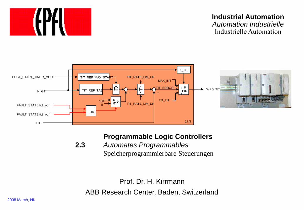
Programmable Logic Controllers
2.3 Automates Programmables
Speicherprogrammierbare Steuerungen
lim
TIT
TIT_REF_TAB N_GT
POST_START_TIMER_MOD
100 0 FAULT_STATE[tit1_oor]
FAULT_STATE[tit2_oor] OR
TIT_RATE_LIM_DN
TIT_RATE_LIM_UP
TIT_ERROR
TIT_REF_MAX_START
WFD_TIT PID
K_TIT
P
TD_TIT
D
MAX_INT
I
17.3
2008 March, HK
Industrial Automation Automation Industrielle Industrielle Automation
Prof. Dr. H. Kirrmann
ABB Research Center, Baden, Switzerland
2 2.3 Programmable Logic Controllers Industrial Automation
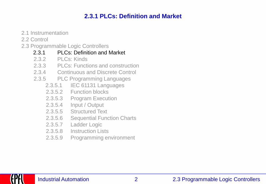
2.3.1 PLCs: Definition and Market
2.1 Instrumentation
2.2 Control
2.3 Programmable Logic Controllers
2.3.1 PLCs: Definition and Market
2.3.2 PLCs: Kinds
2.3.3 PLCs: Functions and construction
2.3.4 Continuous and Discrete Control
2.3.5 PLC Programming Languages
2.3.5.1 IEC 61131 Languages
2.3.5.2 Function blocks
2.3.5.3 Program Execution
2.3.5.4 Input / Output
2.3.5.5 Structured Text
2.3.5.6 Sequential Function Charts
2.3.5.7 Ladder Logic
2.3.5.8 Instruction Lists
2.3.5.9 Programming environment
3 2.3 Programmable Logic Controllers Industrial Automation
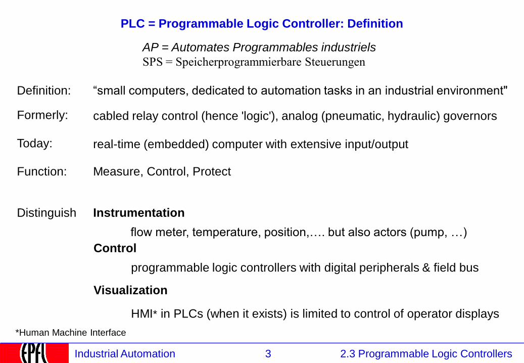
PLC = Programmable Logic Controller: Definition
Definition: “small computers, dedicated to automation tasks in an industrial environment"
cabled relay control (hence 'logic'), analog (pneumatic, hydraulic) governors
real-time (embedded) computer with extensive input/output
Function: Measure, Control, Protect
AP = Automates Programmables industriels
SPS = Speicherprogrammierbare Steuerungen
Formerly:
Today:
Distinguish Instrumentation
flow meter, temperature, position,…. but also actors (pump, …)
Control
programmable logic controllers with digital peripherals & field bus
Visualization
HMI* in PLCs (when it exists) is limited to control of operator displays
*Human Machine Interface
4 2.3 Programmable Logic Controllers Industrial Automation
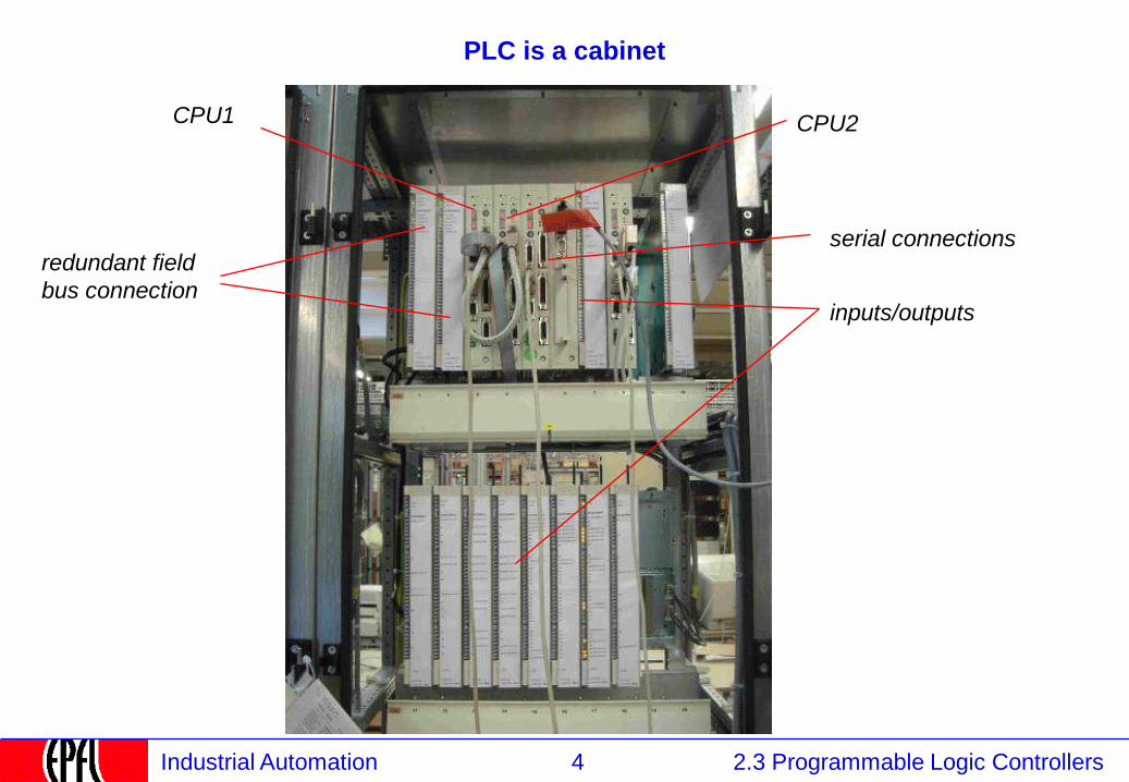
PLC is a cabinet
CPU1
redundant field
bus connection
CPU2
inputs/outputs
serial connections

5 2.3 Programmable Logic Controllers Industrial Automation
example: turbine control (in the test lab)
6 2.3 Programmable Logic Controllers Industrial Automation
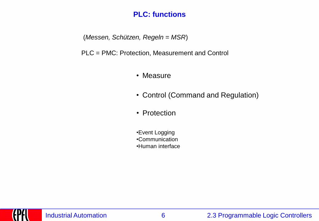
PLC: functions
Measure
Control (Command and Regulation)
•
•
•Event Logging
•Communication
•Human interface
Protection •
(Messen, Schützen, Regeln = MSR)
PLC = PMC: Protection, Measurement and Control
7 2.3 Programmable Logic Controllers Industrial Automation
PLC: Characteristics
• large number of peripherals: 20..100 I/O per CPU, high density of wiring, easy assembly.
• binary and analog Input/Output with standard levels
• located near the plant (field level), require robust construction, protection against dirt,
water and mechanical threats, electro-magnetic noise, vibration, extreme temperature
range (-30C..85C)
• programming: either very primitive with hand-help terminals on the target machine
itself, or with a lap-top able to down-load programs.
• network connection is becoming common, allowing programming on workstations.
• primitive Man-Machine interface, either through LCD-display or connection of a laptop
over serial lines (RS232).
• economical - €1000.- .. €15'000.- for a full crate.
• the value is in the application software (licenses €20'000 ..€50'000)
• field bus connection for remote I/Os
8 2.3 Programmable Logic Controllers Industrial Automation
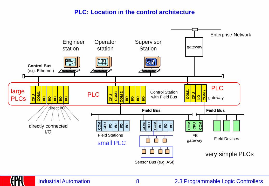
PLC: Location in the control architecture
Enterprise Network
directly connected
I/O
Control Bus
(e.g. Ethernet)
Engineer
station I/
O
I/O
I/O
I/O
CP
U
Sensor Bus (e.g. ASI)
Field Bus
gateway
Field Stations
Control Station with Field Bus
direct I/O
I/O
Field Devices FB
gateway
gateway
I/O
I/O
I/O
I/O
CP
U
CO
M
I/O
I/O
I/O
CO
M
CP
U
CO
M
CO
M
CO
M
I/O
Field Bus
CP
U
CO
M 2
I/O
I/O
I/O
CP
U
CO
M1
CO
M 2
I/O
CP
U
Operator
station
large
PLCs
small PLC
very simple PLCs
PLC PLC
CO
M1
CO
M1
Supervisor
Station
9 2.3 Programmable Logic Controllers Industrial Automation
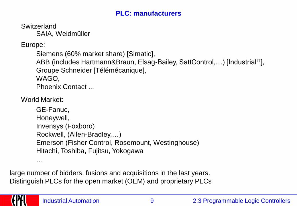
PLC: manufacturers
Europe:
Siemens (60% market share) [Simatic],
ABB (includes Hartmann&Braun, Elsag-Bailey, SattControl,…) [IndustrialIT],
Groupe Schneider [Télémécanique],
WAGO,
Phoenix Contact ...
World Market:
GE-Fanuc,
Honeywell,
Invensys (Foxboro)
Rockwell, (Allen-Bradley,…)
Emerson (Fisher Control, Rosemount, Westinghouse)
Hitachi, Toshiba, Fujitsu, Yokogawa
…
SAIA, Weidmüller Switzerland
large number of bidders, fusions and acquisitions in the last years.
Distinguish PLCs for the open market (OEM) and proprietary PLCs
10 2.3 Programmable Logic Controllers Industrial Automation
2.3.3 PLCs: Kinds
2.1 Instrumentation
2.2 Control
2.3 Programmable Logic Controllers
2.3.1 PLCs: Definition and Market
2.3.2 PLCs: Kinds
2.3.3 PLCs: Functions and construction
2.3.4 Continuous and Discrete Control
2.3.5 PLC Programming Languages
2.3.5.1 IEC 61131 Languages
2.3.5.2 Function blocks
2.3.5.3 Program Execution
2.3.5.4 Input / Output
2.3.5.5 Structured Text
2.3.5.6 Sequential Function Charts
2.3.5.7 Ladder Logic
2.3.5.8 Instruction Lists
2.3.5.9 Programming environment
11 2.3 Programmable Logic Controllers Industrial Automation
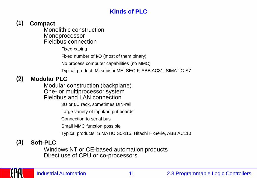
Kinds of PLC
Monolithic construction
Monoprocessor
Fieldbus connection Fixed casing
Fixed number of I/O (most of them binary)
No process computer capabilities (no MMC)
Typical product: Mitsubishi MELSEC F, ABB AC31, SIMATIC S7
(1)
Modular construction (backplane)
One- or multiprocessor system
Fieldbus and LAN connection 3U or 6U rack, sometimes DIN-rail
Large variety of input/output boards
Connection to serial bus
Small MMC function possible
Typical products: SIMATIC S5-115, Hitachi H-Serie, ABB AC110
(2)
Compact
Modular PLC
(3) Soft-PLC Windows NT or CE-based automation products Direct use of CPU or co-processors

12 2.3 Programmable Logic Controllers Industrial Automation
courtesy ABB
Modular PLC
RS232
CPU CPU Analog I/O Binary I/O
backplane
parallel bus
• housed in a 19" (42 cm) rack
(height 6U ( = 233 mm) or 3U (=100mm)
• concentration of a large number of I/O
Power Supply
• high processing power (several CPU)
• primitive or no HMI
• cost effective if the rack can be filled
• tailored to the needs of an application
• supply 115-230V~ , 24V= or 48V= (redundant)
fieldbus
LAN
• large choice of I/O boards
• interface boards to field busses
• requires marshalling of signals
fieldbus
development
environment
�
• cost ~ €10’000 for a filled crate
13 2.3 Programmable Logic Controllers Industrial Automation
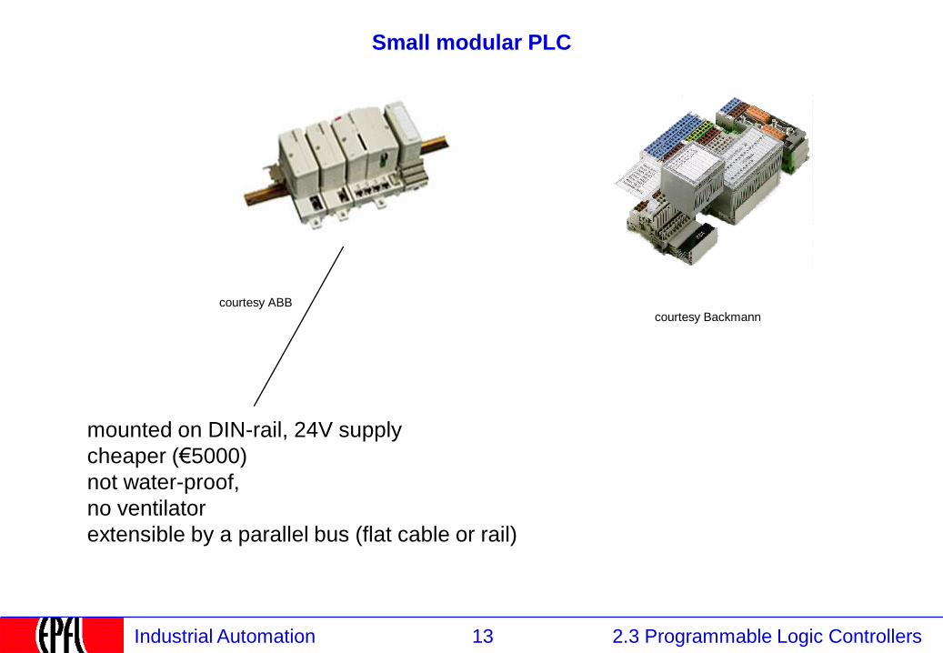
Small modular PLC
mounted on DIN-rail, 24V supply
cheaper (€5000)
not water-proof,
no ventilator
extensible by a parallel bus (flat cable or rail)
courtesy ABB
courtesy Backmann
14 2.3 Programmable Logic Controllers Industrial Automation
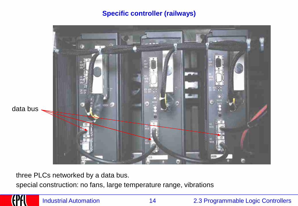
Specific controller (railways)
data bus
special construction: no fans, large temperature range, vibrations
three PLCs networked by a data bus.
15 2.3 Programmable Logic Controllers Industrial Automation
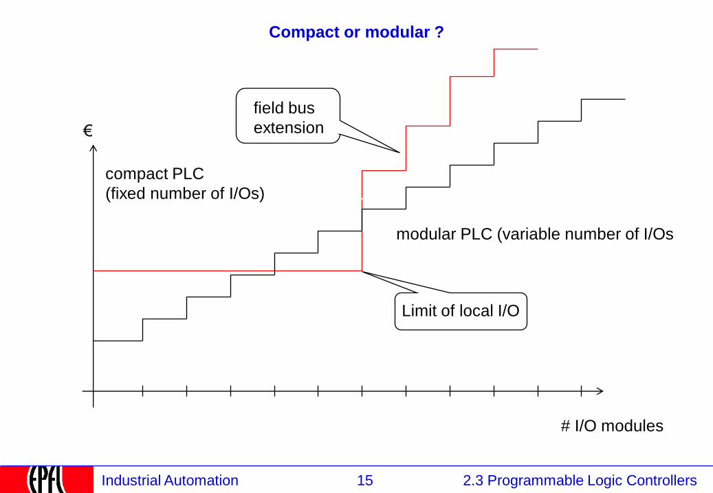
Compact or modular ?
€
# I/O modules
Limit of local I/O
compact PLC
(fixed number of I/Os)
modular PLC (variable number of I/Os
field bus
extension
16 2.3 Programmable Logic Controllers Industrial Automation
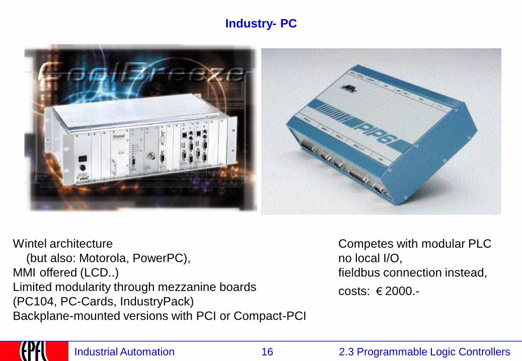
Industry- PC
Wintel architecture
(but also: Motorola, PowerPC),
MMI offered (LCD..)
Limited modularity through mezzanine boards
(PC104, PC-Cards, IndustryPack)
Backplane-mounted versions with PCI or Compact-PCI
Competes with modular PLC
no local I/O,
fieldbus connection instead,
courtesy INOVA courtesy MPI
costs: € 2000.-

17 2.3 Programmable Logic Controllers Industrial Automation
Soft-PLC (PC as PLC)
• PC as engineering workstation • PC as human interface (Visual Basic, Intellution, Wonderware)
• PC as real-time processor (Soft-PLC)
• PC assisted by a Co-Processor (ISA- or PC104 board)
• PC as field bus gateway to a distributed I/O system
2 12
2
3
3
23
4
I/O modules
18 2.3 Programmable Logic Controllers Industrial Automation
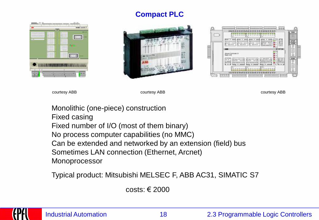
Compact PLC
Monolithic (one-piece) construction
Fixed casing
Fixed number of I/O (most of them binary)
No process computer capabilities (no MMC)
Can be extended and networked by an extension (field) bus
Sometimes LAN connection (Ethernet, Arcnet)
Monoprocessor
Typical product: Mitsubishi MELSEC F, ABB AC31, SIMATIC S7
costs: € 2000
courtesy ABB courtesy ABB courtesy ABB
19 2.3 Programmable Logic Controllers Industrial Automation
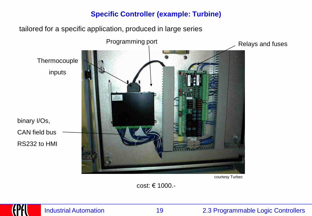
Specific Controller (example: Turbine)
Thermocouple
inputs
binary I/Os,
CAN field bus
RS232 to HMI
Relays and fuses Programming port
cost: € 1000.-
tailored for a specific application, produced in large series
courtesy Turbec
20 2.3 Programmable Logic Controllers Industrial Automation
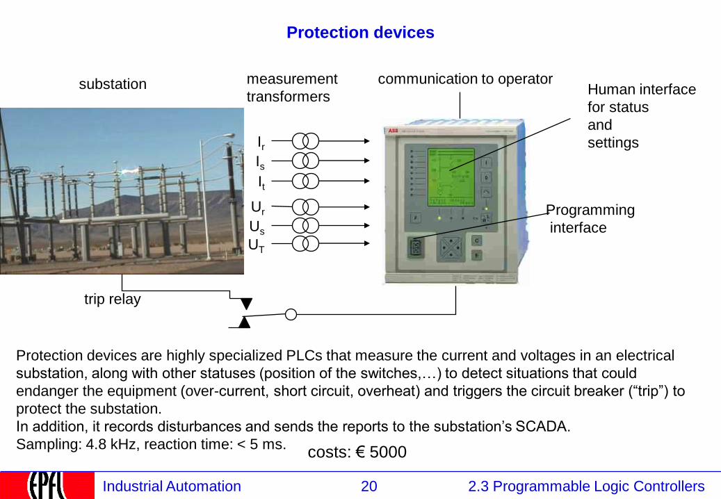
Protection devices
Protection devices are highly specialized PLCs that measure the current and voltages in an electrical
substation, along with other statuses (position of the switches,…) to detect situations that could
endanger the equipment (over-current, short circuit, overheat) and triggers the circuit breaker (“trip”) to
protect the substation.
In addition, it records disturbances and sends the reports to the substation’s SCADA.
Sampling: 4.8 kHz, reaction time: < 5 ms.
Human interface
for status
and
settings
measurement
transformers
Ir Is
It
Ur
Us
UT
Programming
interface
trip relay
communication to operator
costs: € 5000
substation
21 2.3 Programmable Logic Controllers Industrial Automation
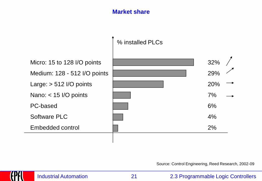
Market share
Micro: 15 to 128 I/O points
Medium: 128 - 512 I/O points
Large: > 512 I/O points
Nano: < 15 I/O points
PC-based
Software PLC
Embedded control
32%
29%
20%
7%
6%
4%
2%
% installed PLCs
Source: Control Engineering, Reed Research, 2002-09
22 2.3 Programmable Logic Controllers Industrial Automation
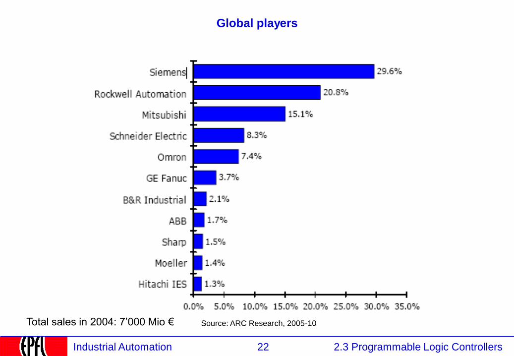
Global players
Total sales in 2004: 7’000 Mio € Source: ARC Research, 2005-10

23 2.3 Programmable Logic Controllers Industrial Automation
Comparison Criteria – Example
Siemens
Number of Points
Memory
Programming Language
Programming Tools
Download
Real estate per 250 I/O
Label surface
Network
Hitachi
640
16 KB
• Ladder Logic
• Instructions
• Logic symbols
• Basic
• Hand-terminal
• Graphic on PC
yes
1000 cm2
6 characters
6 mm2
19.2 kbit/s
1024
• Ladder logic
• Instructions
• Logic symbols
• Hand-terminal
• Graphic on PC
no
2678 cm2
5.3 mm2
7 characters per line/point
10 Mbit/s
10 KB
Mounting cabinet DIN rail
Brand
24 2.3 Programmable Logic Controllers Industrial Automation
2.3.3 PLCs: Function and construction
2.1 Instrumentation
2.2 Control
2.3 Programmable Logic Controllers
2.3.1 PLCs: Definition and Market
2.3.2 PLCs: Kinds
2.3.3 PLCs: Functions and construction
2.3.4 Continuous and Discrete Control
2.3.5 PLC Programming Languages
2.3.5.1 IEC 61131 Languages
2.3.5.2 Function blocks
2.3.5.3 Program Execution
2.3.5.4 Input / Output
2.3.5.5 Structured Text
2.3.5.6 Sequential Function Charts
2.3.5.7 Ladder Logic
2.3.5.8 Instruction Lists
2.3.5.9 Programming environment
25 2.3 Programmable Logic Controllers Industrial Automation
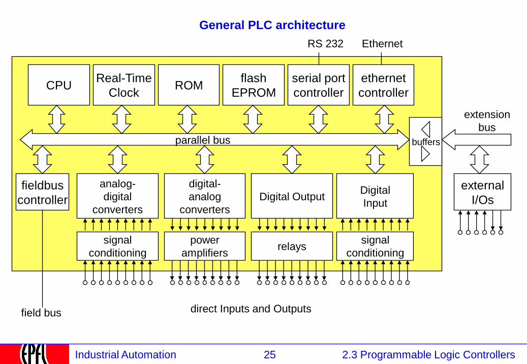
General PLC architecture
CPU Real-Time
Clock
flash
EPROM ROM
buffers
signal
conditioning
power
amplifiers relays
signal
conditioning
serial port
controller
Ethernet
parallel bus
ethernet
controller
RS 232
analog-
digital
converters
digital-
analog
converters
Digital Output Digital
Input
fieldbus
controller
external
I/Os
extension
bus
field bus direct Inputs and Outputs
26 2.3 Programmable Logic Controllers Industrial Automation
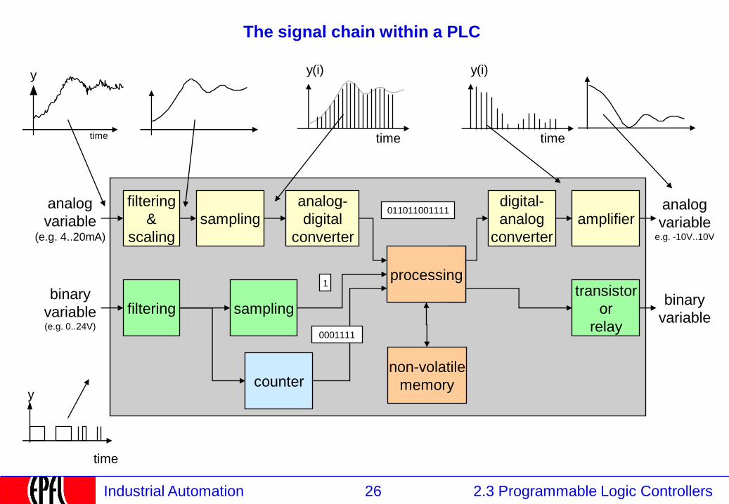
The signal chain within a PLC
analog
variable (e.g. 4..20mA)
filtering
&
scaling
analog-
digital
converter
processing
digital-
analog
converter
analog
variable e.g. -10V..10V
time
y
time
y(i)
sampling
binary
variable (e.g. 0..24V)
filtering sampling
time
y
transistor
or
relay
binary
variable
amplifier 011011001111
counter
1
non-volatile
memory
0001111
time
y(i)
27 2.3 Programmable Logic Controllers Industrial Automation
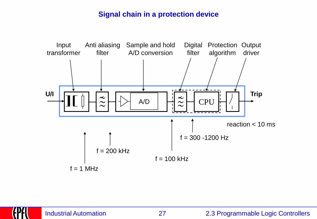
Signal chain in a protection device
A/D CPU U/I Trip
Digital
filter
Sample and hold
A/D conversion
Input
transformer
Anti aliasing
filter
Protection
algorithm
Output
driver
f = 1 MHz
f = 200 kHz
f = 100 kHz
f = 300 -1200 Hz
reaction < 10 ms
28 2.3 Programmable Logic Controllers Industrial Automation
2.3.4 Continuous and discrete control
2.1 Instrumentation
2.2 Control
2.3 Programmable Logic Controllers
2.3.1 PLCs: Definition and Market
2.3.2 PLCs: Kinds
2.3.3 PLCs: Functions and construction
2.3.4 Continuous and Discrete Control
2.3.5 PLC Programming Languages
2.3.5.1 IEC 61131 Languages
2.3.5.2 Function blocks
2.3.5.3 Program Execution
2.3.5.4 Input / Output
2.3.5.5 Structured Text
2.3.5.6 Sequential Function Charts
2.3.5.7 Ladder Logic
2.3.5.8 Instruction Lists
2.3.5.9 Programming environment

29 2.3 Programmable Logic Controllers Industrial Automation
Matching the analog and binary world
discrete control analog regulation
30 2.3 Programmable Logic Controllers Industrial Automation
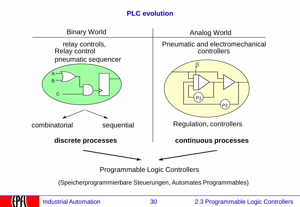
PLC evolution
A
B
P2
P1
I1
Analog World Binary World
C
continuous processes
Regulation, controllers
discrete processes
combinatorial sequential
relay controls, Relay control
pneumatic sequencer
Pneumatic and electromechanical controllers
Programmable Logic Controllers
(Speicherprogrammierbare Steuerungen, Automates Programmables)
31 2.3 Programmable Logic Controllers Industrial Automation
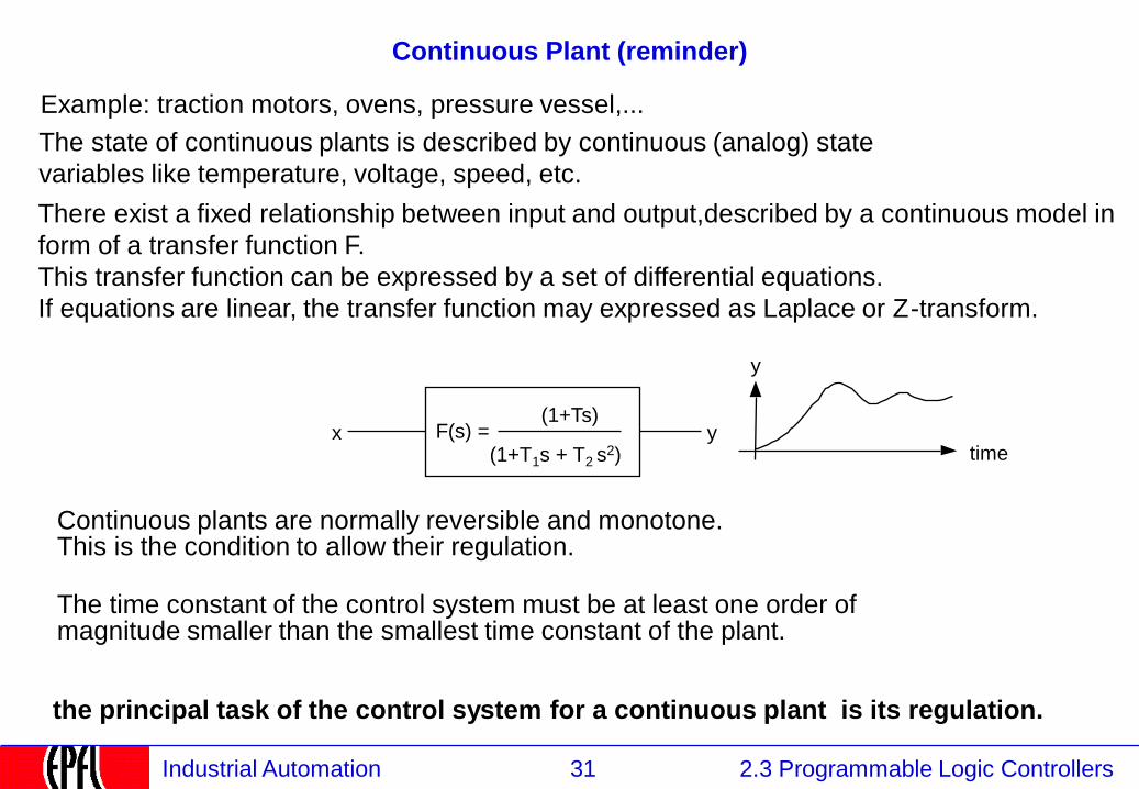
Continuous Plant (reminder)
Example: traction motors, ovens, pressure vessel,...
The time constant of the control system must be at least one order of magnitude smaller than the smallest time constant of the plant.
F(s) = y x
The state of continuous plants is described by continuous (analog) state
variables like temperature, voltage, speed, etc.
Continuous plants are normally reversible and monotone. This is the condition to allow their regulation.
There exist a fixed relationship between input and output,described by a continuous model in
form of a transfer function F.
This transfer function can be expressed by a set of differential equations.
If equations are linear, the transfer function may expressed as Laplace or Z-transform.
time
y
(1+Ts)
(1+T1s + T2 s2)
the principal task of the control system for a continuous plant is its regulation.
32 2.3 Programmable Logic Controllers Industrial Automation
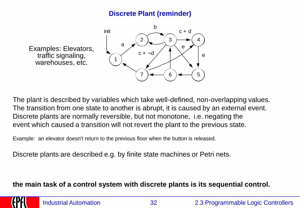
Discrete Plant (reminder)
Examples: Elevators, traffic signaling, warehouses, etc.
The plant is described by variables which take well-defined, non-overlapping values.
The transition from one state to another is abrupt, it is caused by an external event.
Discrete plants are normally reversible, but not monotone, i.e. negating the
event which caused a transition will not revert the plant to the previous state.
Example: an elevator doesn't return to the previous floor when the button is released.
Discrete plants are described e.g. by finite state machines or Petri nets.
the main task of a control system with discrete plants is its sequential control.
e
c + ¬d1
2 3
6 5
4
7
a
bc + d
e
init
33 2.3 Programmable Logic Controllers Industrial Automation
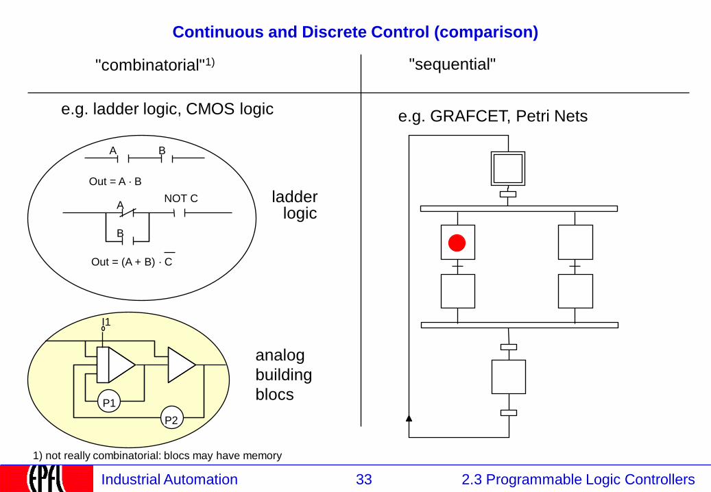
Continuous and Discrete Control (comparison)
A B
Out = A · B
B
NOT C A
Out = (A + B) · C
"sequential" "combinatorial"1)
ladder logic
e.g. GRAFCET, Petri Nets e.g. ladder logic, CMOS logic
P2
P1
I1
analog
building
blocs
1) not really combinatorial: blocs may have memory
34 2.3 Programmable Logic Controllers Industrial Automation
2.3.5 Programming languages
2.1 Instrumentation
2.2 Control
2.3 Programmable Logic Controllers
2.3.1 PLCs: Definition and Market
2.3.2 PLCs: Kinds
2.3.3 PLCs: Functions and construction
2.3.4 Continuous and Discrete Control
2.3.5 Programming languages
2.3.5.1 IEC 61131 Languages
2.3.5.2 Function blocks
2.3.5.3 Program Execution
2.3.5.4 Input / Output
2.3.5.5 Structured Text
2.3.5.6 Sequential Function Charts
2.3.5.7 Ladder Logic
2.3.5.8 Instruction Lists
2.3.5.9 Programming environment
35 2.3 Programmable Logic Controllers Industrial Automation
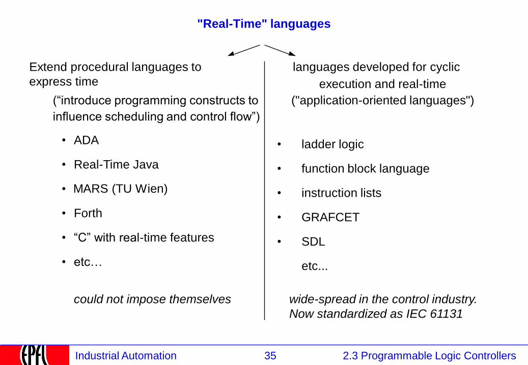
"Real-Time" languages
Extend procedural languages to
express time
(“introduce programming constructs to
influence scheduling and control flow”)
languages developed for cyclic
execution and real-time
("application-oriented languages")
ladder logic
function block language
instruction lists
GRAFCET
SDL
etc...
•
•
•
•
•
wide-spread in the control industry.
Now standardized as IEC 61131
ADA
Real-Time Java
MARS (TU Wien)
Forth
“C” with real-time features
etc…
could not impose themselves
•
•
•
•
•
•
36 2.3 Programmable Logic Controllers Industrial Automation
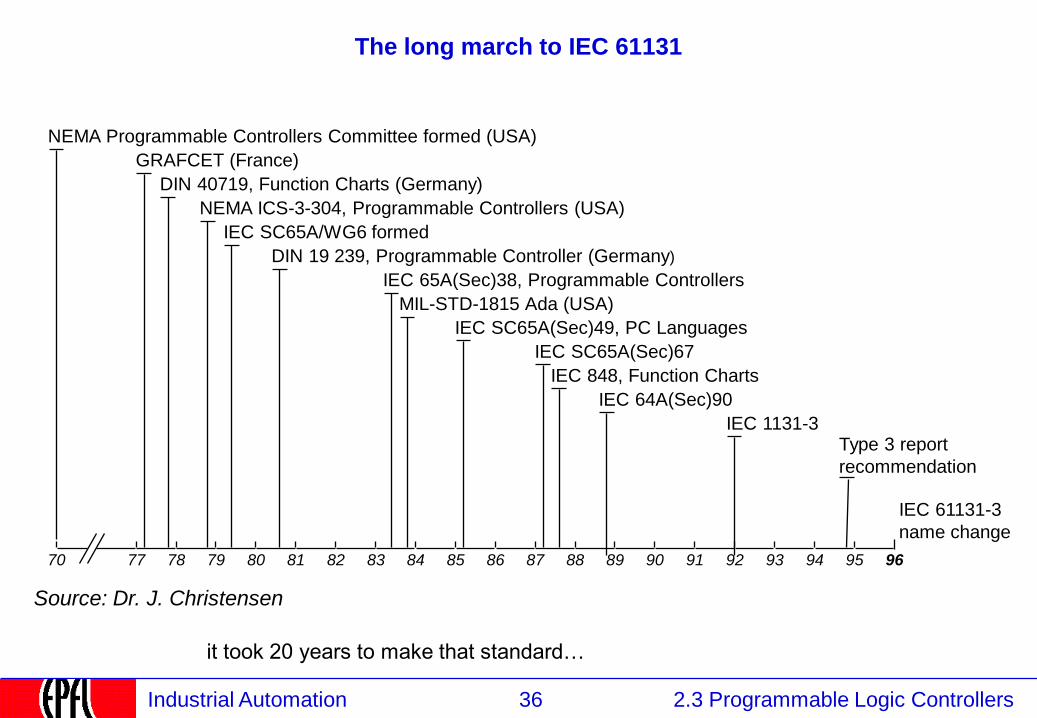
The long march to IEC 61131
Source: Dr. J. Christensen
77 78 79 81 80 93 94 95 70 82 83 84 85 87 86 88 89 90 91 92
NEMA Programmable Controllers Committee formed (USA)
GRAFCET (France)
IEC 848, Function Charts
DIN 40719, Function Charts (Germany)
NEMA ICS-3-304, Programmable Controllers (USA)
IEC SC65A/WG6 formed
DIN 19 239, Programmable Controller (Germany)
MIL-STD-1815 Ada (USA)
IEC SC65A(Sec)67
Type 3 report
recommendation
96
IEC 65A(Sec)38, Programmable Controllers
IEC 1131-3
IEC SC65A(Sec)49, PC Languages
IEC 64A(Sec)90
IEC 61131-3
name change
it took 20 years to make that standard…
37 2.3 Programmable Logic Controllers Industrial Automation
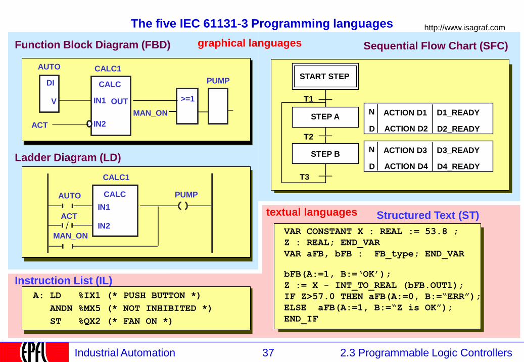
The five IEC 61131-3 Programming languages
Structured Text (ST)
VAR CONSTANT X : REAL := 53.8 ;
Z : REAL; END_VAR
VAR aFB, bFB : FB_type; END_VAR
bFB(A:=1, B:=„OK‟);
Z := X - INT_TO_REAL (bFB.OUT1);
IF Z>57.0 THEN aFB(A:=0, B:=“ERR”);
ELSE aFB(A:=1, B:=“Z is OK”);
END_IF
Ladder Diagram (LD)
OUT
PUMP
http://www.isagraf.com
Function Block Diagram (FBD)
PUMP
AUTO
MAN_ON
ACT
DO
V
Instruction List (IL)
A: LD %IX1 (* PUSH BUTTON *)
ANDN %MX5 (* NOT INHIBITED *)
ST %QX2 (* FAN ON *)
Sequential Flow Chart (SFC)
START STEP
T1
T2
D1_READY
D2_READY
STEP A ACTION D1 N
D ACTION D2
STEP B D3_READY
D4_READY
ACTION D3 N
D ACTION D4
T3
DI
V
CALC1
CALC
IN1
IN2
OUT >=1
graphical languages
textual languages
AUTO
MAN_ON
ACT
CALC1
CALC
IN1
IN2
38 2.3 Programmable Logic Controllers Industrial Automation
Importance of IEC 61131
IEC 61131-3 is the most important automation language in industry.
80% of all PLCs support it, all new developments base on it.
Depending on the country, some languages are more popular.
39 2.3 Programmable Logic Controllers Industrial Automation
2.4.2.1 Function Blocks Language
2.1 Instrumentation
2.2 Control
2.3 Programmable Logic Controllers
2.3.1 PLCs: Definition and Market
2.3.2 PLCs: Kinds
2.3.3 PLCs: Functions and construction
2.3.4 Continuous and Discrete Control
2.3.5 PLC Programming Languages
2.3.5.1 IEC 61131 Languages
2.3.5.2 Function blocks language
2.3.5.3 Program Execution
2.3.5.4 Input / Output
2.3.5.5 Structured Text
2.3.5.6 Sequential Function Charts
2.3.5.7 Ladder Logic
2.3.5.8 Instruction Lists
2.3.5.9 Programming environment
40 2.3 Programmable Logic Controllers Industrial Automation
Function Block Languages
The function block languages express "combinatorial"
programs in a way similar to electronic circuits.
They draw on a large variety of predefined and custom functions
This language is similar to the Matlab / Simulink language used in simulations
(Funktionsblocksprache, langage de blocs de fonctions)
(Also called "Function Chart" or "Function Plan" - FuPla)
41 2.3 Programmable Logic Controllers Industrial Automation
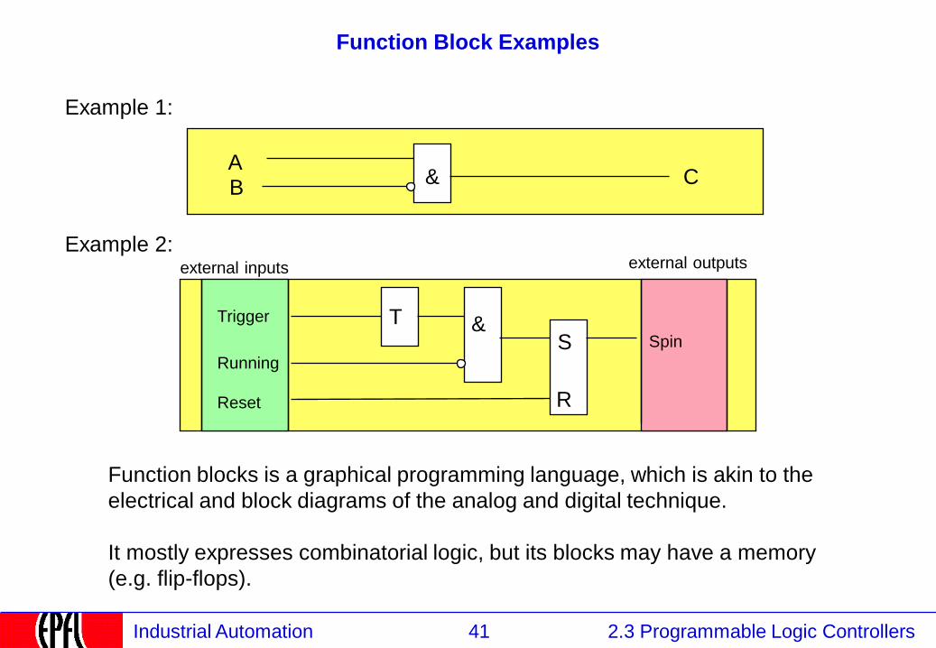
Function Block Examples
& A B
C
Trigger T &
Running
Reset
S
R
Spin
Function blocks is a graphical programming language, which is akin to the
electrical and block diagrams of the analog and digital technique.
It mostly expresses combinatorial logic, but its blocks may have a memory
(e.g. flip-flops).
Example 1:
Example 2: external inputs external outputs
42 2.3 Programmable Logic Controllers Industrial Automation
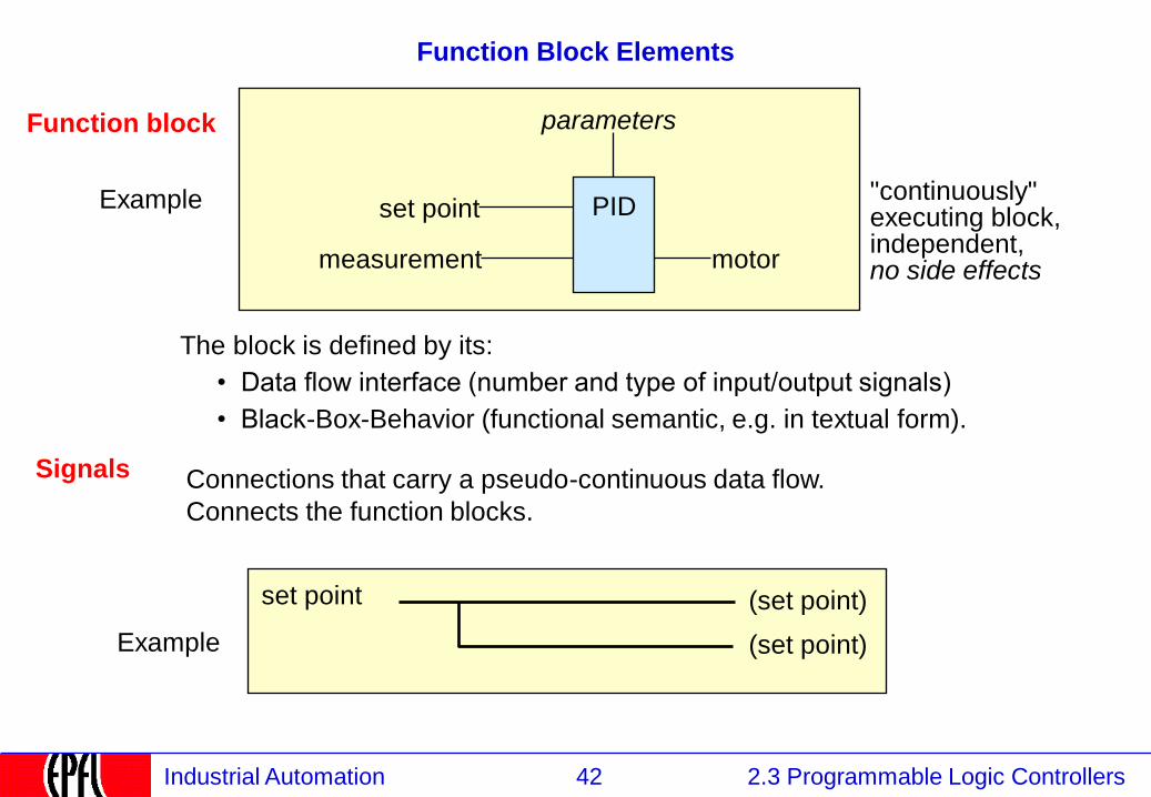
Function Block Elements
"continuously" executing block, independent, no side effects
set point
measurement motor
parameters
The block is defined by its:
• Data flow interface (number and type of input/output signals)
• Black-Box-Behavior (functional semantic, e.g. in textual form).
Connections that carry a pseudo-continuous data flow.
Connects the function blocks.
Signals
Function block
(set point)
(set point)
set point
Example
Example
PID
43 2.3 Programmable Logic Controllers Industrial Automation
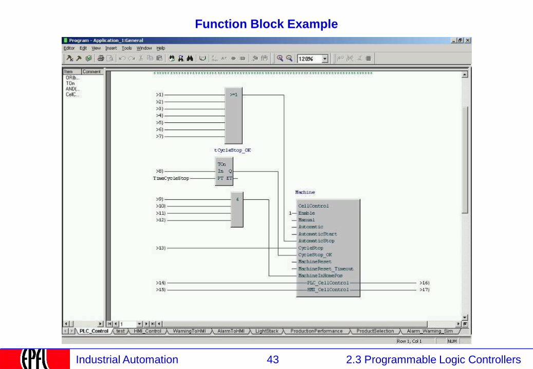
Function Block Example
44 2.3 Programmable Logic Controllers Industrial Automation
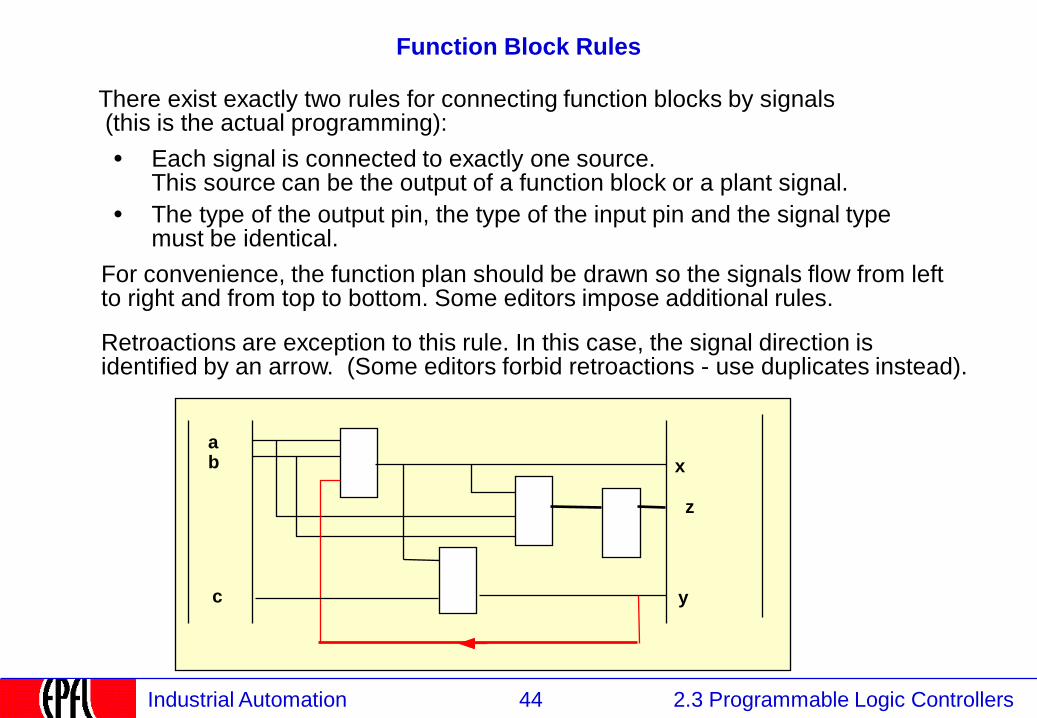
Function Block Rules
There exist exactly two rules for connecting function blocks by signals (this is the actual programming):
Each signal is connected to exactly one source. This source can be the output of a function block or a plant signal.
The type of the output pin, the type of the input pin and the signal type must be identical.
•
•
For convenience, the function plan should be drawn so the signals flow from left to right and from top to bottom. Some editors impose additional rules.
Retroactions are exception to this rule. In this case, the signal direction is identified by an arrow. (Some editors forbid retroactions - use duplicates instead).
a b
y
x
z
c
45 2.3 Programmable Logic Controllers Industrial Automation
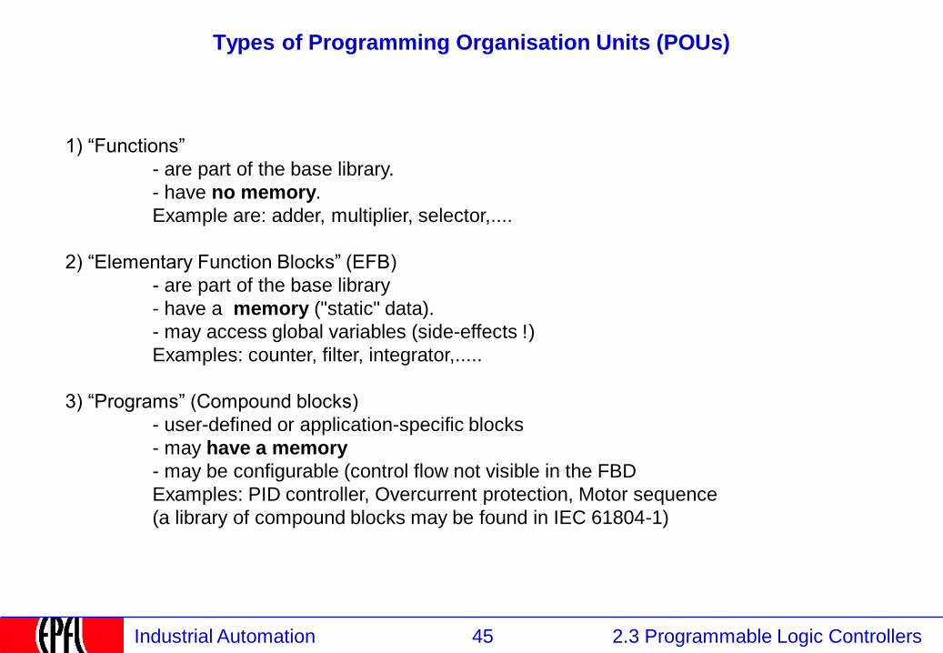
Types of Programming Organisation Units (POUs)
1) “Functions”
- are part of the base library.
- have no memory.
Example are: adder, multiplier, selector,....
2) “Elementary Function Blocks” (EFB)
- are part of the base library
- have a memory ("static" data).
- may access global variables (side-effects !)
Examples: counter, filter, integrator,.....
3) “Programs” (Compound blocks)
- user-defined or application-specific blocks
- may have a memory
- may be configurable (control flow not visible in the FBD
Examples: PID controller, Overcurrent protection, Motor sequence
(a library of compound blocks may be found in IEC 61804-1)
46 2.3 Programmable Logic Controllers Industrial Automation
Function Block library
The programmer chooses the blocks in a block library, similarly to the
hardware engineer who chooses integrated circuits out of the catalogue.
This library indicates the pinning of each block, its semantics and the execution time.
The programmer may extend the library by defining function block macros out of
library elements.
If some blocks are often used, they will be programmed in an external language
(e.g. “C”, micro-code) following strict rules.
47 2.3 Programmable Logic Controllers Industrial Automation
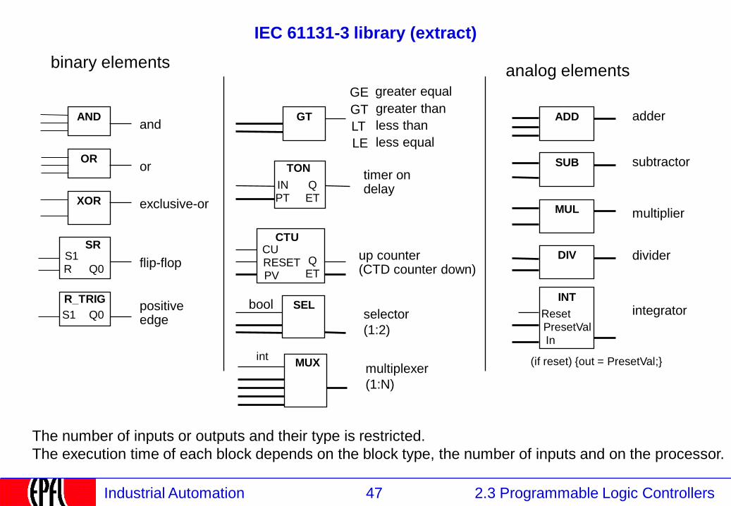
IEC 61131-3 library (extract)
binary elements
ADD
analog elements
SUB
MUL
DIV
adder
INT
PresetVal selector
(1:2)
timer on delay
AND
OR
XOR
S1 SR
Q0
S1
R_TRIG
Q0
R
subtractor
multiplier
divider
integrator
greater than
less than
up counter (CTD counter down)
GT
LT
LE less equal
and
or
exclusive-or
flip-flop
positive edge
GT
SEL
IN
TON
Q PT ET
CTU CU RESET PV
Q ET
The number of inputs or outputs and their type is restricted.
The execution time of each block depends on the block type, the number of inputs and on the processor.
In
Reset
greater equal GE
(if reset) {out = PresetVal;} multiplexer
(1:N)
MUX
bool
int
48 2.3 Programmable Logic Controllers Industrial Automation
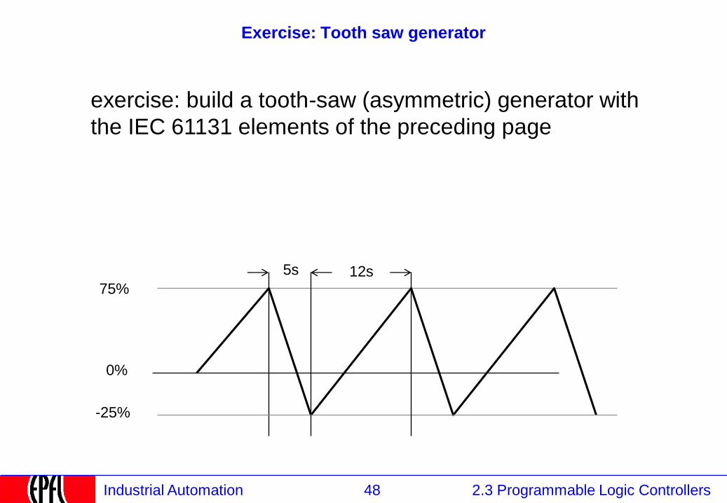
Exercise: Tooth saw generator
exercise: build a tooth-saw (asymmetric) generator with
the IEC 61131 elements of the preceding page
75%
0%
-25%
5s 12s
49 2.3 Programmable Logic Controllers Industrial Automation
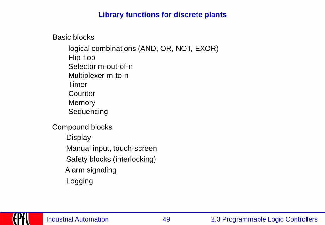
Library functions for discrete plants
logical combinations (AND, OR, NOT, EXOR)
Flip-flop
Selector m-out-of-n
Multiplexer m-to-n
Timer
Counter
Memory
Sequencing
Basic blocks
Display
Manual input, touch-screen
Safety blocks (interlocking)
Logging
Compound blocks
Alarm signaling
50 2.3 Programmable Logic Controllers Industrial Automation
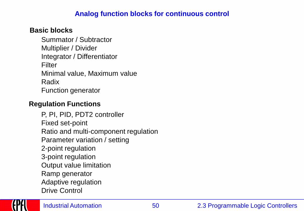
Analog function blocks for continuous control
Basic blocks
Summator / Subtractor
Multiplier / Divider
Integrator / Differentiator
Filter
Minimal value, Maximum value
Radix
Function generator
Regulation Functions
P, PI, PID, PDT2 controller
Fixed set-point
Ratio and multi-component regulation
Parameter variation / setting
2-point regulation
3-point regulation
Output value limitation
Ramp generator
Adaptive regulation
Drive Control
51 2.3 Programmable Logic Controllers Industrial Automation
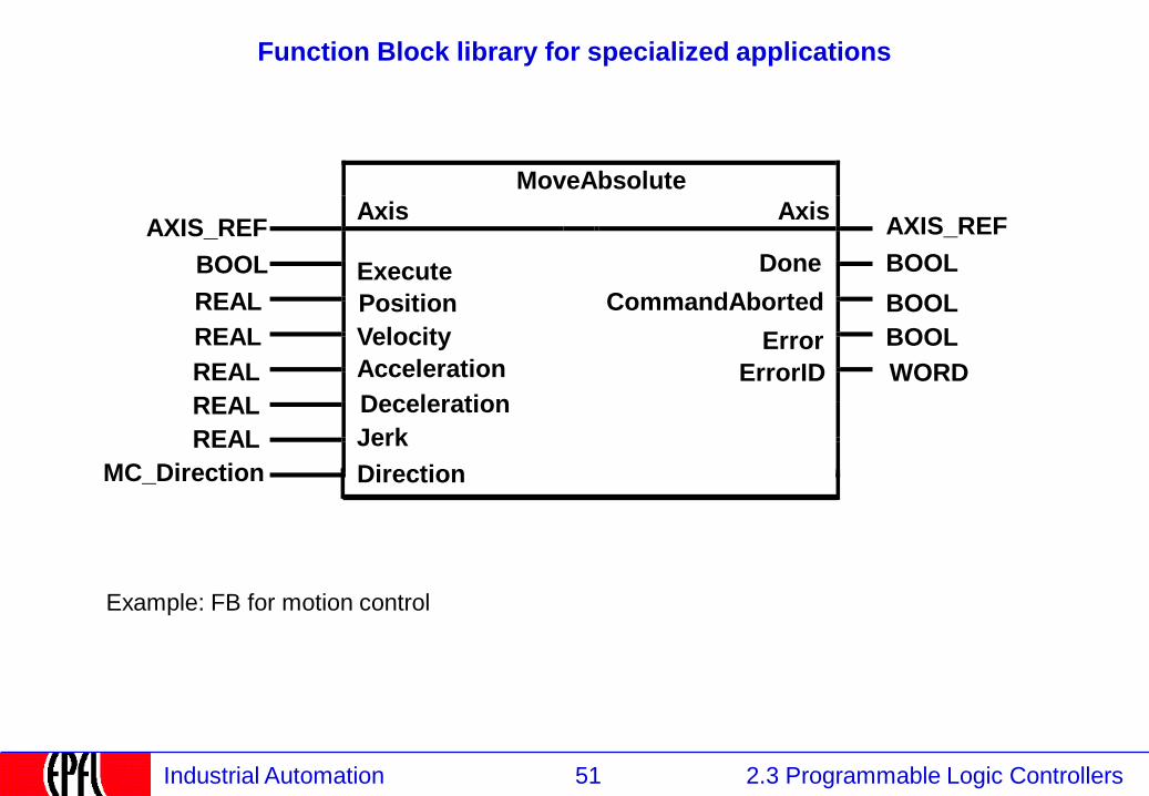
Function Block library for specialized applications
MoveAbsolute
AXIS_REF Axis Axis
AXIS_REF
BOOL Execute Done BOOL
REAL Position BOOL
REAL Velocity
CommandAborted
WORD REAL Acceleration
BOOL
REAL Deceleration
REAL Jerk
MC_Direction Direction
Error
ErrorID
Example: FB for motion control
52 2.3 Programmable Logic Controllers Industrial Automation
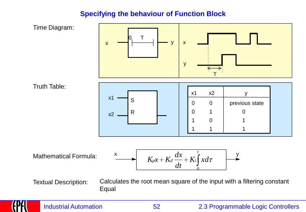
Specifying the behaviour of Function Block
Time Diagram:
0 T
T
x
y
y x
S
R
x1
0
0
1
1
x2
0
1
0
1
y
previous state
0
1
1
Truth Table:
Mathematical Formula:
x1
x2
Textual Description:
y x t
idp xdKdt
dxKxK
0
Calculates the root mean square of the input with a filtering constant
Equal
53 2.3 Programmable Logic Controllers Industrial Automation
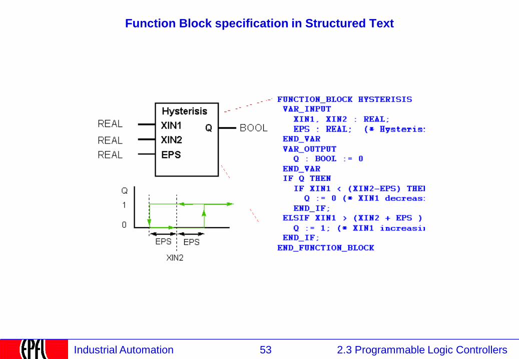
Function Block specification in Structured Text
54 2.3 Programmable Logic Controllers Industrial Automation
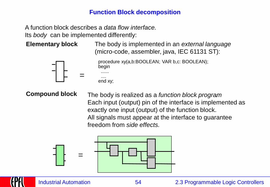
Function Block decomposition
A function block describes a data flow interface.
Its body can be implemented differently:
The body is implemented in an external language
(micro-code, assembler, java, IEC 61131 ST):
Elementary block
The body is realized as a function block program
Each input (output) pin of the interface is implemented as
exactly one input (output) of the function block.
All signals must appear at the interface to guarantee
freedom from side effects.
. Compound block
procedure xy(a,b:BOOLEAN; VAR b,c: BOOLEAN); begin ...... .... end xy;
=
=
55 2.3 Programmable Logic Controllers Industrial Automation
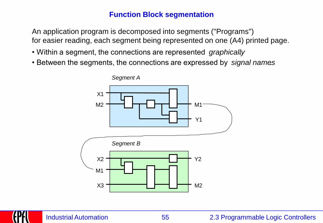
Function Block segmentation
An application program is decomposed into segments ("Programs")
for easier reading, each segment being represented on one (A4) printed page.
• Within a segment, the connections are represented graphically .
• Between the segments, the connections are expressed by signal names .
Segment A
Segment B
X1
M2 M1
Y1
Y2
M2
X2
M1
X3
56 2.3 Programmable Logic Controllers Industrial Automation
2.3.5.3 Program execution
2.1 Instrumentation
2.2 Control
2.3 Programmable Logic Controllers
2.3.1 PLCs: Definition and Market
2.3.2 PLCs: Kinds
2.3.3 PLCs: Functions and construction
2.3.4 Continuous and Discrete Control
2.3.5 PLC Programming Languages
2.3.5.1 IEC 61131 Languages
2.3.5.2 Function blocks
2.3.5.3 Program Execution
2.3.5.4 Input / Output
2.3.5.5 Structured Text
2.3.5.6 Sequential Function Charts
2.3.5.7 Ladder Logic
2.3.5.8 Instruction Lists
2.3.5.9 Programming environment
57 2.3 Programmable Logic Controllers Industrial Automation
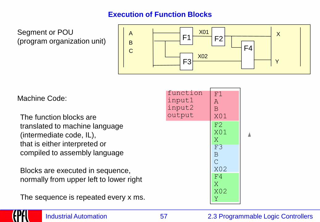
Execution of Function Blocks
F1 A B X01
F2 X01 X F3 B C X02 F4 X X02 Y
Machine Code: function input1 input2 output
A F1 F2
B F4
Y
X01
X02 F3
C
X Segment or POU
(program organization unit)
The function blocks are
translated to machine language
(intermediate code, IL),
that is either interpreted or
compiled to assembly language
Blocks are executed in sequence,
normally from upper left to lower right
The sequence is repeated every x ms.
58 2.3 Programmable Logic Controllers Industrial Automation
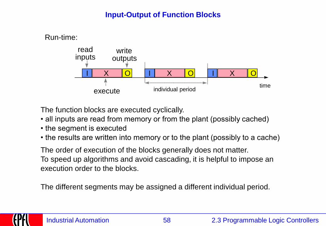
Input-Output of Function Blocks
execute individual period
I O X I O X I O X
read inputs
write
outputs
Run-time:
The function blocks are executed cyclically.
• all inputs are read from memory or from the plant (possibly cached)
• the segment is executed
• the results are written into memory or to the plant (possibly to a cache)
The order of execution of the blocks generally does not matter.
To speed up algorithms and avoid cascading, it is helpful to impose an
execution order to the blocks.
The different segments may be assigned a different individual period.
time
59 2.3 Programmable Logic Controllers Industrial Automation
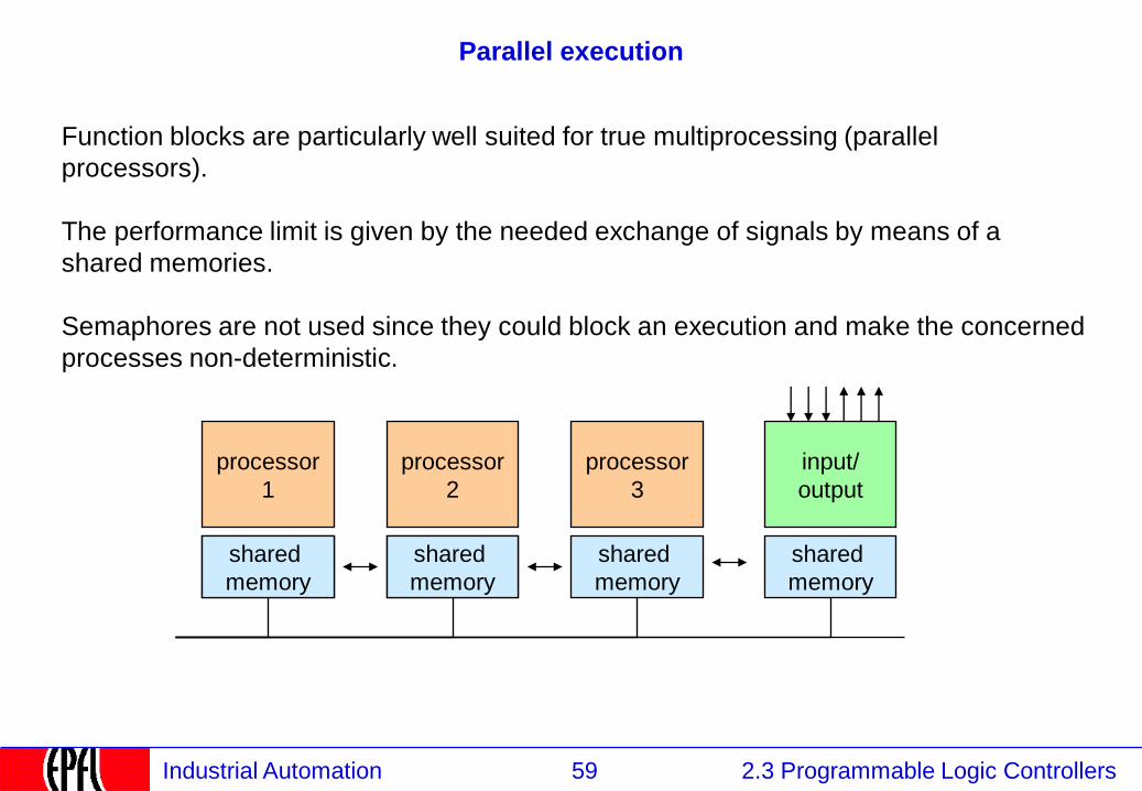
Parallel execution
Function blocks are particularly well suited for true multiprocessing (parallel
processors).
The performance limit is given by the needed exchange of signals by means of a
shared memories.
Semaphores are not used since they could block an execution and make the concerned
processes non-deterministic.
processor
1
processor
2
processor
3
shared
memory
shared
memory
shared
memory
shared
memory
input/
output
60 2.3 Programmable Logic Controllers Industrial Automation
Program configuration
The programmer divides the program into tasks (sometimes called pages or segments),
which may be executed each with a different period.
The programmer assigns each task (each page) an execution period.
Since the execution time of each block in a task is fixed, the execution time is fixed.
Event-driven operations are encapsulated into blocks, e.g. for transmitting messages.
If the execution time of these tasks cannot be bound, they are executed in background.
The periodic execution always has the highest priority.
61 2.3 Programmable Logic Controllers Industrial Automation
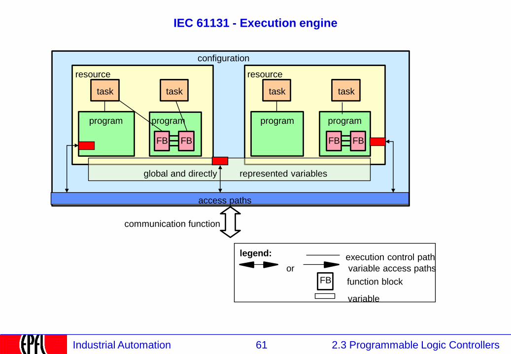
IEC 61131 - Execution engine
configuration
resource
task task
program program
FB FB
task
execution control path
variable access paths
FB function block
variable
or
represented variables
communication function
legend:
program
FB FB
resource
task
program
global and directly
access paths

62 2.3 Programmable Logic Controllers Industrial Automation
2.3.5.4 Input and Output
2.1 Instrumentation
2.2 Control
2.3 Programmable Logic Controllers
2.3.1 PLCs: Definition and Market
2.3.2 PLCs: Kinds
2.3.3 PLCs: Functions and construction
2.3.4 Continuous and Discrete Control
2.3.5 PLC Programming Languages
2.3.5.1 IEC 61131 Languages
2.3.5.2 Function blocks
2.3.5.3 Program Execution
2.3.5.4 Input & Output
2.3.5.5 Structured Text
2.3.5.6 Sequential Function Charts
2.3.5.7 Ladder Logic
2.3.5.8 Instruction Lists
2.3.5.9 Programming environment
63 2.3 Programmable Logic Controllers Industrial Automation
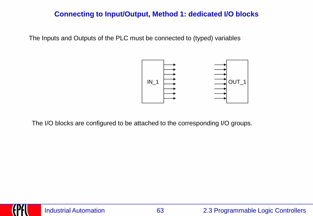
Connecting to Input/Output, Method 1: dedicated I/O blocks
The Inputs and Outputs of the PLC must be connected to (typed) variables
OUT_1
The I/O blocks are configured to be attached to the corresponding I/O groups.
IN_1
64 2.3 Programmable Logic Controllers Industrial Automation
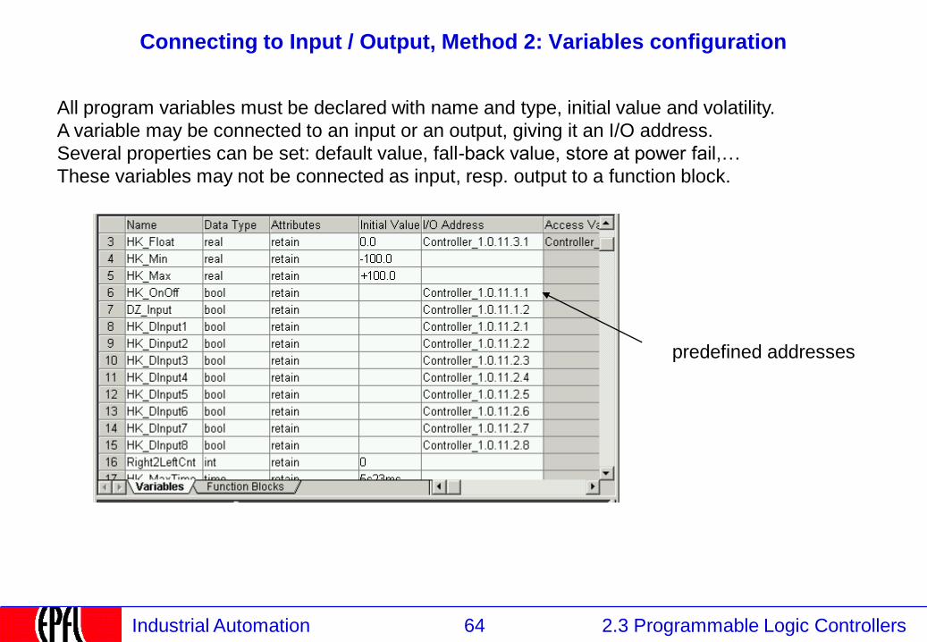
Connecting to Input / Output, Method 2: Variables configuration
All program variables must be declared with name and type, initial value and volatility.
A variable may be connected to an input or an output, giving it an I/O address.
Several properties can be set: default value, fall-back value, store at power fail,…
These variables may not be connected as input, resp. output to a function block.
predefined addresses
65 2.3 Programmable Logic Controllers Industrial Automation
2.3.5.5 Structured Text
2.1 Instrumentation
2.2 Control
2.3 Programmable Logic Controllers
2.3.1 PLCs: Definition and Market
2.3.2 PLCs: Kinds
2.3.3 PLCs: Functions and construction
2.3.4 Continuous and Discrete Control
2.3.5 PLC Programming Languages
2.3.5.1 IEC 61131 Languages
2.3.5.2 Function blocks
2.3.5.3 Program Execution
2.3.5.4 Input / Output
2.3.5.5 Structured Text
2.3.5.6 Sequential Function Charts
2.3.5.7 Ladder Logic
2.3.5.8 Programming environment
66 2.3 Programmable Logic Controllers Industrial Automation
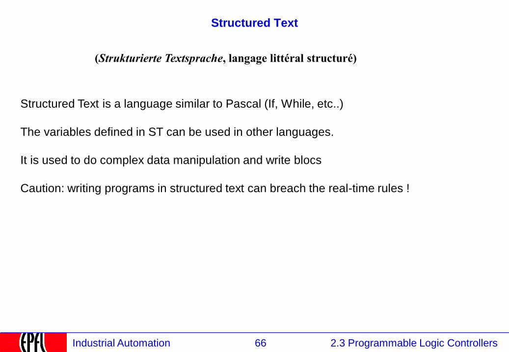
Structured Text
(Strukturierte Textsprache, langage littéral structuré)
Structured Text is a language similar to Pascal (If, While, etc..)
The variables defined in ST can be used in other languages.
It is used to do complex data manipulation and write blocs
Caution: writing programs in structured text can breach the real-time rules !
67 2.3 Programmable Logic Controllers Industrial Automation
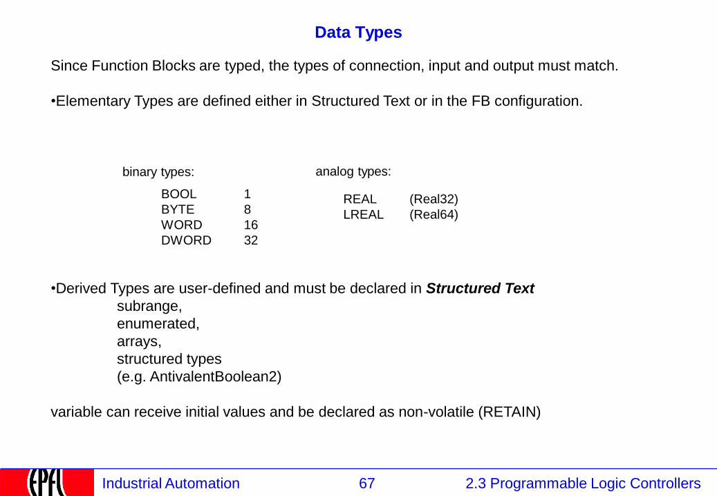
Data Types
binary types: analog types:
•Derived Types are user-defined and must be declared in Structured Text
subrange,
enumerated,
arrays,
structured types
(e.g. AntivalentBoolean2)
variable can receive initial values and be declared as non-volatile (RETAIN)
BOOL
BYTE
WORD
DWORD
1
8
16
32
REAL (Real32)
LREAL (Real64)
Since Function Blocks are typed, the types of connection, input and output must match.
•Elementary Types are defined either in Structured Text or in the FB configuration.
68 2.3 Programmable Logic Controllers Industrial Automation
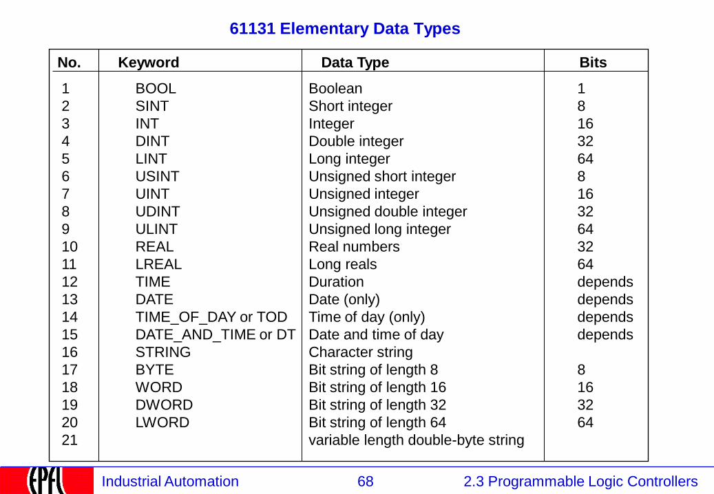
61131 Elementary Data Types
1 BOOL Boolean 1
2 SINT Short integer 8
3 INT Integer 16
4 DINT Double integer 32
5 LINT Long integer 64
6 USINT Unsigned short integer 8
7 UINT Unsigned integer 16
8 UDINT Unsigned double integer 32
9 ULINT Unsigned long integer 64
10 REAL Real numbers 32
11 LREAL Long reals 64
12 TIME Duration depends
13 DATE Date (only) depends
14 TIME_OF_DAY or TOD Time of day (only) depends
15 DATE_AND_TIME or DT Date and time of day depends
16 STRING Character string
17 BYTE Bit string of length 8 8
18 WORD Bit string of length 16 16
19 DWORD Bit string of length 32 32
20 LWORD Bit string of length 64 64
21 variable length double-byte string
No. Keyword Data Type Bits
69 2.3 Programmable Logic Controllers Industrial Automation
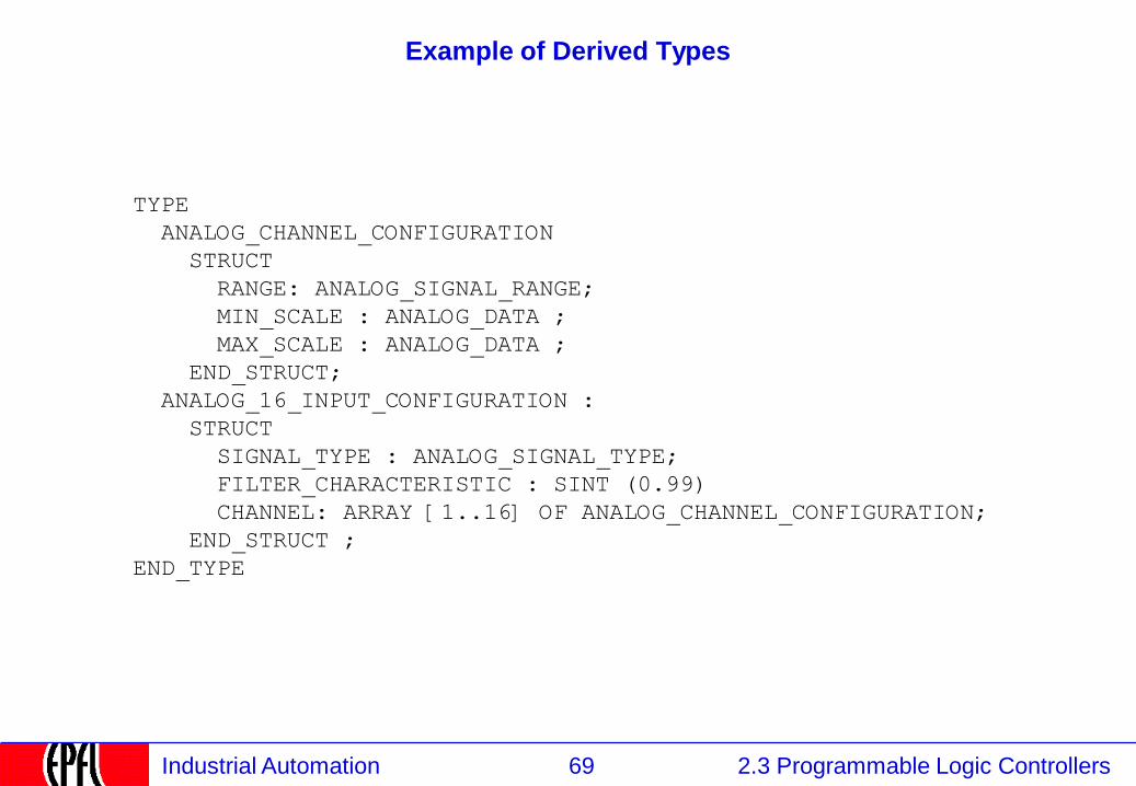
Example of Derived Types
TYPE
ANALOG_CHANNEL_CONFIGURATION
STRUCT
RANGE: ANALOG_SIGNAL_RANGE;
MIN_SCALE : ANALOG_DATA ;
MAX_SCALE : ANALOG_DATA ;
END_STRUCT;
ANALOG_16_INPUT_CONFIGURATION :
STRUCT
SIGNAL_TYPE : ANALOG_SIGNAL_TYPE;
FILTER_CHARACTERISTIC : SINT (0.99)
CHANNEL: ARRAY [1..16] OF ANALOG_CHANNEL_CONFIGURATION;
END_STRUCT ;
END_TYPE

70 2.3 Programmable Logic Controllers Industrial Automation
2.3.5.6 Sequential Function Charts
2.1 Instrumentation
2.2 Control
2.3 Programmable Logic Controllers
2.3.1 PLCs: Definition and Market
2.3.2 PLCs: Kinds
2.3.3 PLCs: Functions and construction
2.3.4 Continuous and Discrete Control
2.3.5 PLC Programming Languages
2.3.5.1 IEC 61131 Languages
2.3.5.2 Function blocks
2.3.5.3 Program Execution
2.3.5.4 Input / Output
2.3.5.5 Structured Text
2.3.5.6 Sequential Function Charts
2.3.5.7 Ladder Logic
2.3.5.8 Programming environment
71 2.3 Programmable Logic Controllers Industrial Automation
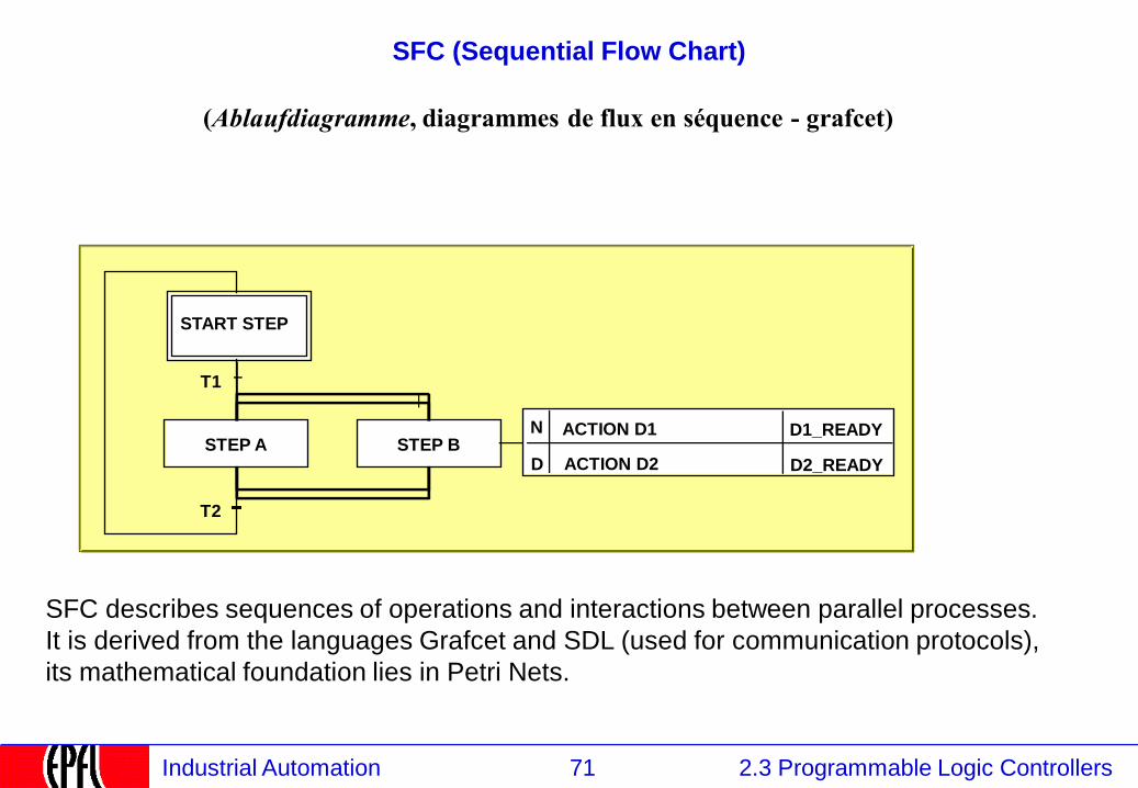
SFC (Sequential Flow Chart)
START STEP
ACTION D1 N D1_READY
D ACTION D2 D2_READY
(Ablaufdiagramme, diagrammes de flux en séquence - grafcet)
SFC describes sequences of operations and interactions between parallel processes.
It is derived from the languages Grafcet and SDL (used for communication protocols),
its mathematical foundation lies in Petri Nets.
T1
T2
STEP B STEP A
72 2.3 Programmable Logic Controllers Industrial Automation
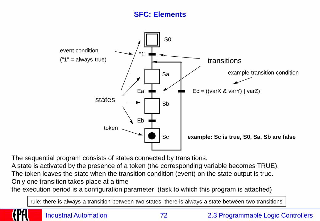
SFC: Elements
Ec = ((varX & varY) | varZ)
The sequential program consists of states connected by transitions.
A state is activated by the presence of a token (the corresponding variable becomes TRUE).
The token leaves the state when the transition condition (event) on the state output is true.
Only one transition takes place at a time
the execution period is a configuration parameter (task to which this program is attached)
token
Sa
Sb
"1"
Ea
Sc
Eb
transitions
states
event condition
("1" = always true)
example transition condition
example: Sc is true, S0, Sa, Sb are false
S0
rule: there is always a transition between two states, there is always a state between two transitions
73 2.3 Programmable Logic Controllers Industrial Automation
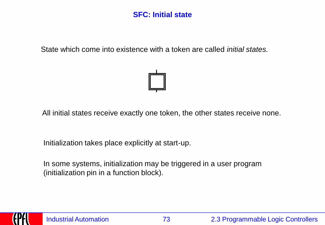
SFC: Initial state
State which come into existence with a token are called initial states.
All initial states receive exactly one token, the other states receive none.
Initialization takes place explicitly at start-up.
In some systems, initialization may be triggered in a user program
(initialization pin in a function block).
74 2.3 Programmable Logic Controllers Industrial Automation
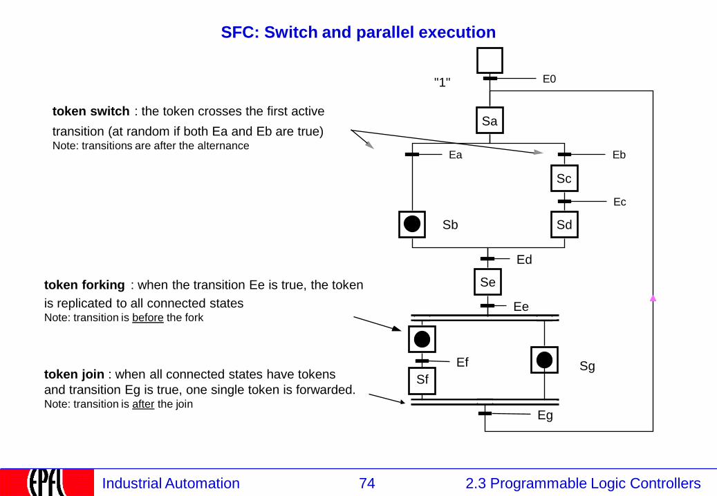
SFC: Switch and parallel execution
Sa
Sb
"1"
Se
token switch : the token crosses the first active
transition (at random if both Ea and Eb are true) Note: transitions are after the alternance
token forking : when the transition Ee is true, the token
is replicated to all connected states Note: transition is before the fork
Ed
token join : when all connected states have tokens
and transition Eg is true, one single token is forwarded. Note: transition is after the join
Ee
Sc
Sd
Sf Sg
Eg
E0
Ea Eb
Ec
Ef
75 2.3 Programmable Logic Controllers Industrial Automation
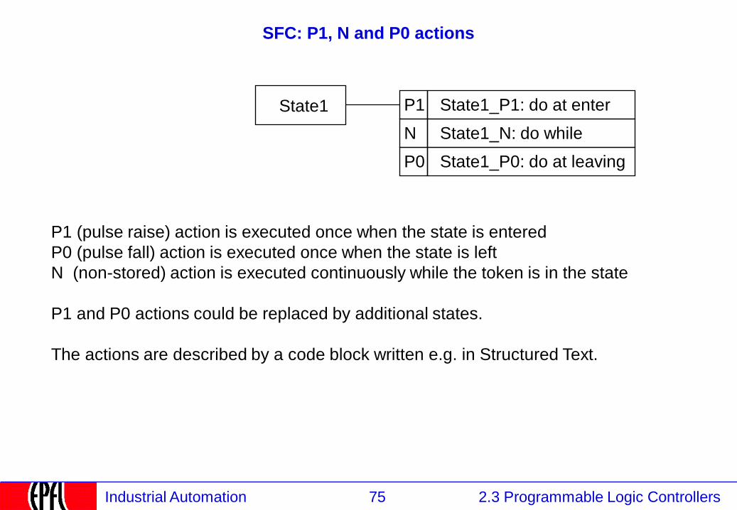
SFC: P1, N and P0 actions
P1 State1_P1: do at enter
N State1_N: do while
P0 State1_P0: do at leaving
State1
P1 (pulse raise) action is executed once when the state is entered
P0 (pulse fall) action is executed once when the state is left
N (non-stored) action is executed continuously while the token is in the state
P1 and P0 actions could be replaced by additional states.
The actions are described by a code block written e.g. in Structured Text.
76 2.3 Programmable Logic Controllers Industrial Automation
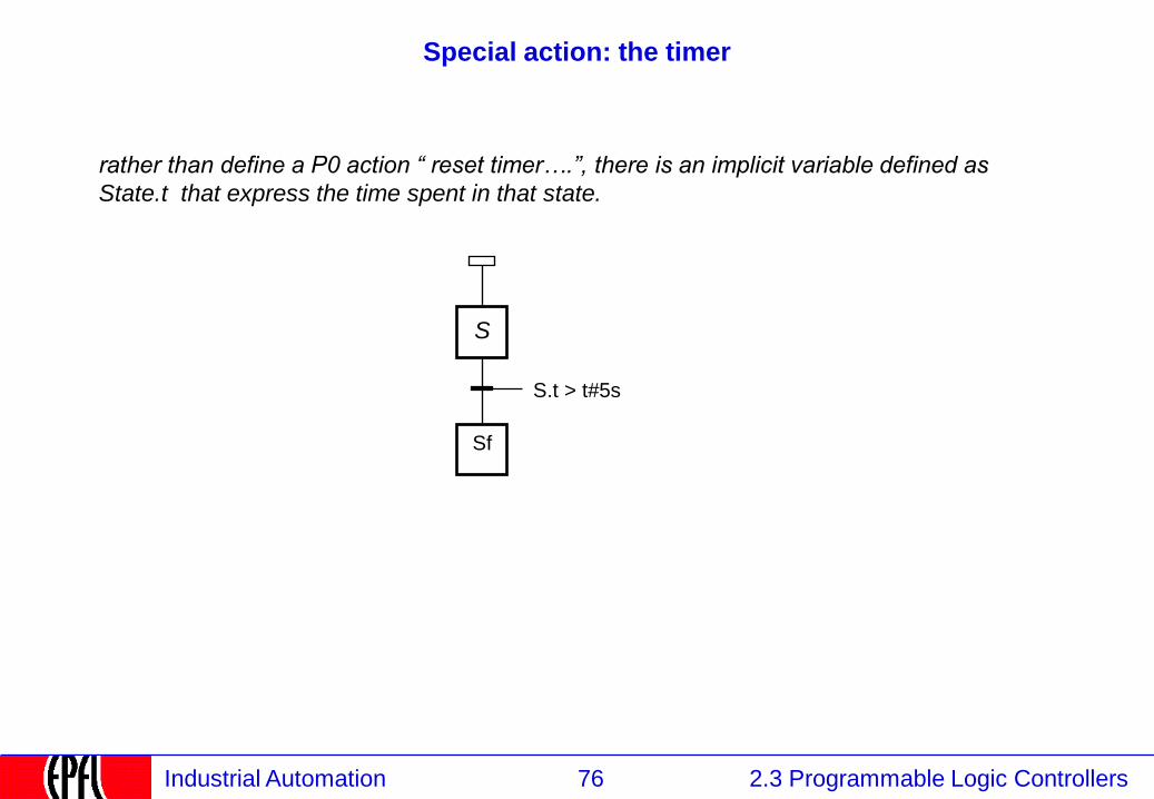
Special action: the timer
rather than define a P0 action “ reset timer….”, there is an implicit variable defined as
State.t that express the time spent in that state.
Sf
S.t > t#5s
S
77 2.3 Programmable Logic Controllers Industrial Automation
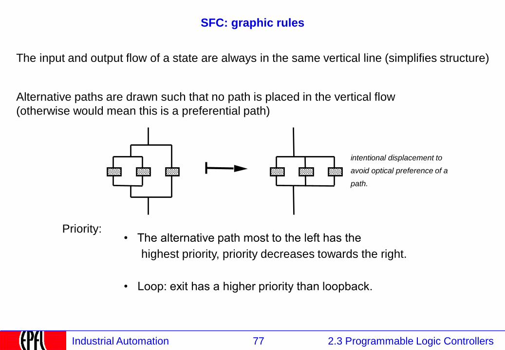
SFC: graphic rules
The input and output flow of a state are always in the same vertical line (simplifies structure)
Alternative paths are drawn such that no path is placed in the vertical flow
(otherwise would mean this is a preferential path)
intentional displacement to
avoid optical preference of a
path.
Priority: • The alternative path most to the left has the
highest priority, priority decreases towards the right.
• Loop: exit has a higher priority than loopback.
78 2.3 Programmable Logic Controllers Industrial Automation
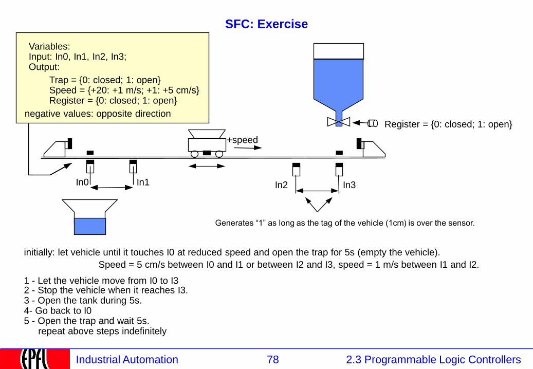
SFC: Exercise
initially: let vehicle until it touches I0 at reduced speed and open the trap for 5s (empty the vehicle).
1 - Let the vehicle move from I0 to I3
Speed = 5 cm/s between I0 and I1 or between I2 and I3, speed = 1 m/s between I1 and I2.
2 - Stop the vehicle when it reaches I3. 3 - Open the tank during 5s. 4- Go back to I0 5 - Open the trap and wait 5s.
repeat above steps indefinitely
In2 In3
Speed = {+20: +1 m/s; +1: +5 cm/s}
negative values: opposite direction
Generates “1” as long as the tag of the vehicle (1cm) is over the sensor.
Register = {0: closed; 1: open}
In0 In1
Variables: Input: In0, In1, In2, In3; Output:
+speed
Trap = {0: closed; 1: open}
Register = {0: closed; 1: open}
79 2.3 Programmable Logic Controllers Industrial Automation
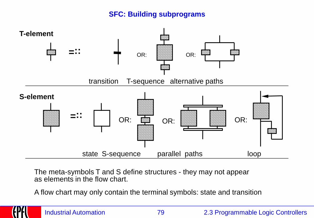
SFC: Building subprograms
::=
::=
OR: OR:
OR: OR:
T-element
S-element
state S-sequence parallel paths
transition T-sequence alternative paths
loop
OR:
The meta-symbols T and S define structures - they may not appear as elements in the flow chart.
A flow chart may only contain the terminal symbols: state and transition
80 2.3 Programmable Logic Controllers Industrial Automation
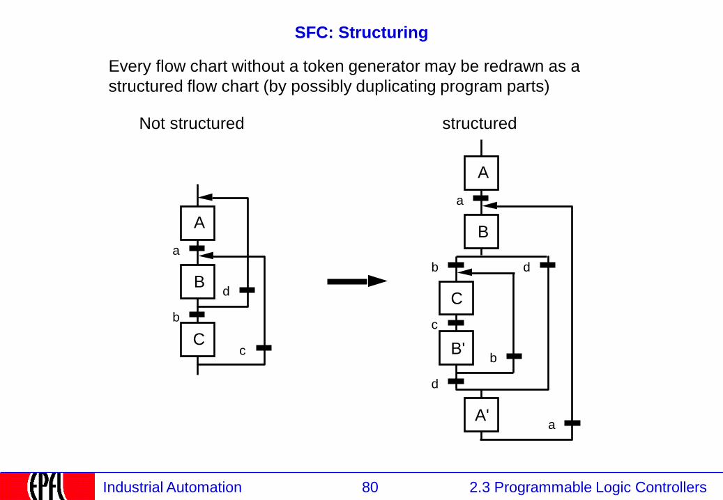
SFC: Structuring
Every flow chart without a token generator may be redrawn as a
structured flow chart (by possibly duplicating program parts)
A
B
C
a
b
d
c
Not structured
A
B
C
a
b
a
b B'
A'
d
c
d
structured
81 2.3 Programmable Logic Controllers Industrial Automation
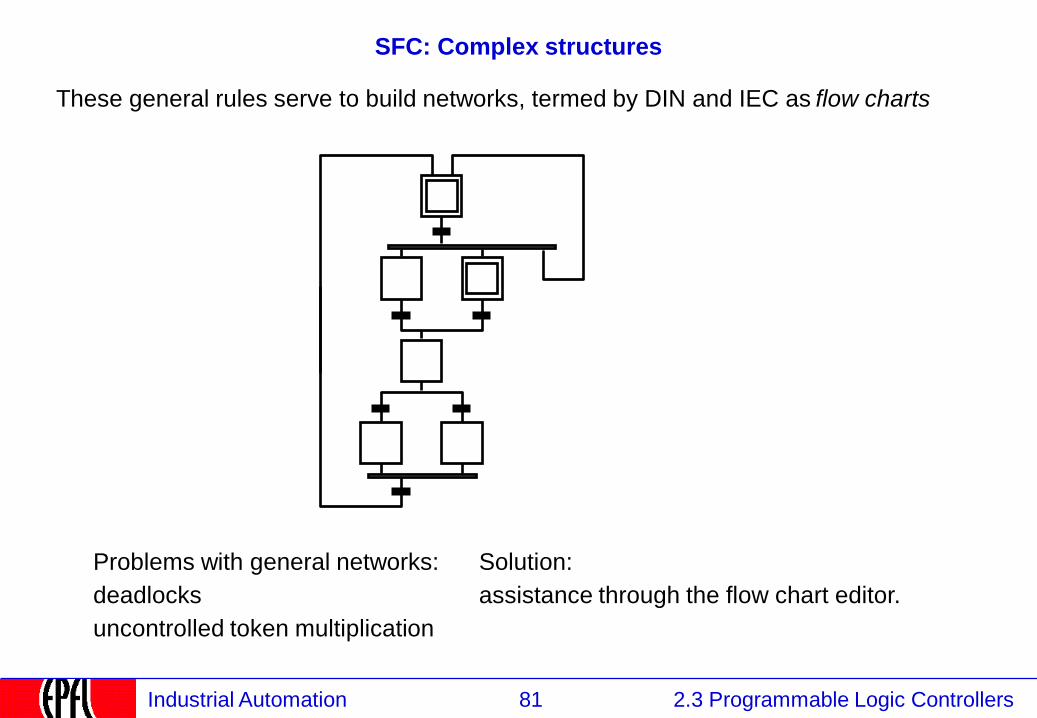
SFC: Complex structures
Problems with general networks:
deadlocks
uncontrolled token multiplication
These general rules serve to build networks, termed by DIN and IEC as flow charts
Solution:
assistance through the flow chart editor.
82 2.3 Programmable Logic Controllers Industrial Automation
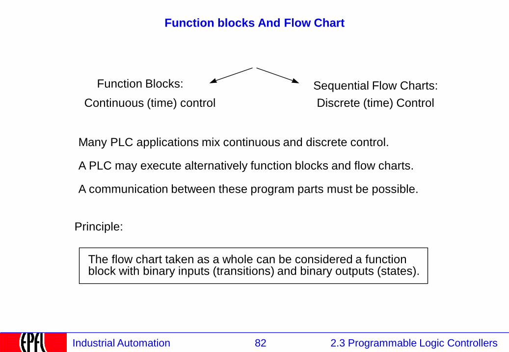
Function blocks And Flow Chart
Function Blocks:
Continuous (time) control
Sequential Flow Charts:
Discrete (time) Control
Many PLC applications mix continuous and discrete control.
A PLC may execute alternatively function blocks and flow charts.
A communication between these program parts must be possible.
Principle:
The flow chart taken as a whole can be considered a function block with binary inputs (transitions) and binary outputs (states).
83 2.3 Programmable Logic Controllers Industrial Automation
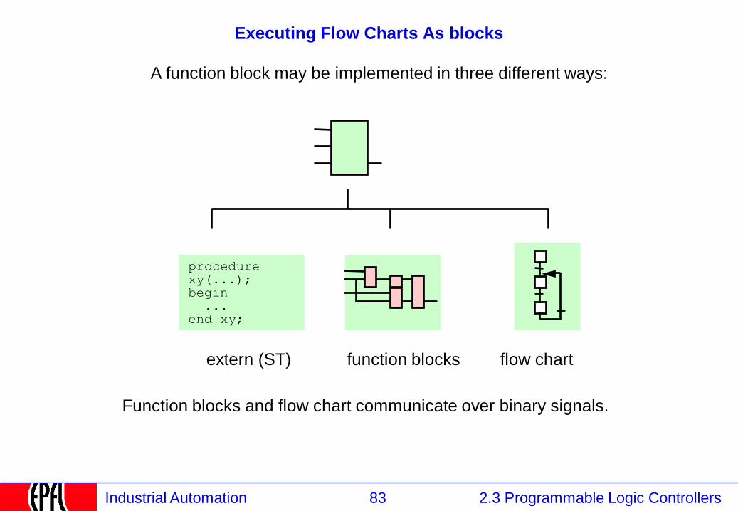
Executing Flow Charts As blocks
A function block may be implemented in three different ways:
procedure xy(...); begin ... end xy;
extern (ST) function blocks flow chart
Function blocks and flow chart communicate over binary signals.
84 2.3 Programmable Logic Controllers Industrial Automation
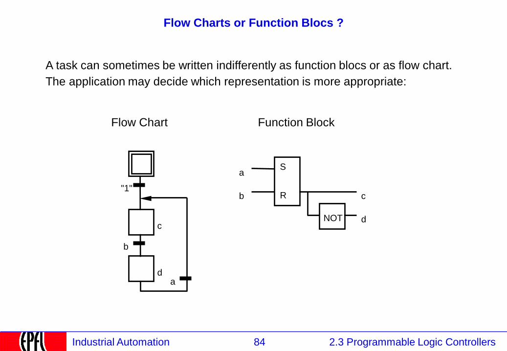
Flow Charts or Function Blocs ?
A task can sometimes be written indifferently as function blocs or as flow chart.
The application may decide which representation is more appropriate:
c
d
"1"
b
a
a
b c
d
Flow Chart Function Block
NOT
S
R
85 2.3 Programmable Logic Controllers Industrial Automation
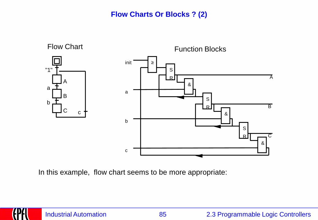
Flow Charts Or Blocks ? (2)
In this example, flow chart seems to be more appropriate:
A
B
C
"1"
a
b
c
S
R
≥
&
S
R
&
S
R
&
init
a
b
c
A
B
C
Flow Chart Function Blocks
86 2.3 Programmable Logic Controllers Industrial Automation
2.3.5.7 Ladder Logic
2.1 Instrumentation
2.2 Control
2.3 Programmable Logic Controllers
2.3.1 PLCs: Definition and Market
2.3.2 PLCs: Kinds
2.3.3 PLCs: Functions and construction
2.3.4 Continuous and Discrete Control
2.3.5 PLC Programming Languages
2.3.5.1 IEC 61131 Languages
2.3.5.2 Function blocks
2.3.5.3 Program Execution
2.3.5.4 Input / Output
2.3.5.5 Structured Text
2.3.5.6 Sequential Function Charts
2.3.5.7 Ladder Logic
2.3.5.8 Programming environment
87 2.3 Programmable Logic Controllers Industrial Automation
Ladder logic (1)
The ladder logic is the oldest programming language for PLC
it bases directly on the relay intuition of the electricians.
it is widely in use outside Europe.
It is described here but not recommended for new projects.
(Kontaktplansprache, langage à contacts)
88 2.3 Programmable Logic Controllers Industrial Automation
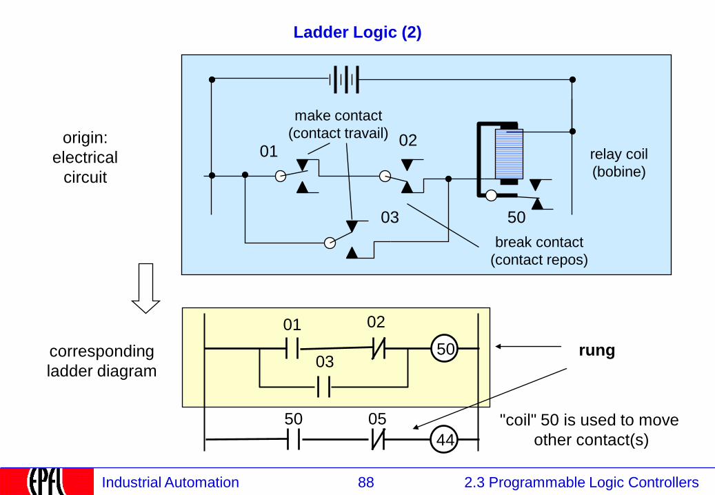
Ladder Logic (2)
01 02
50
01 02
03 50
03
relay coil
(bobine)
break contact
(contact repos)
make contact
(contact travail)
corresponding
ladder diagram
origin:
electrical
circuit
50 05
44
rung
"coil" 50 is used to move
other contact(s)
89 2.3 Programmable Logic Controllers Industrial Automation
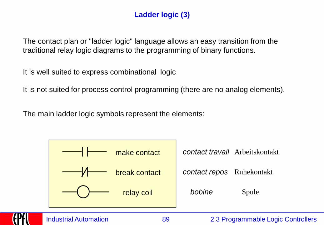
Ladder logic (3)
The contact plan or "ladder logic" language allows an easy transition from the
traditional relay logic diagrams to the programming of binary functions.
It is well suited to express combinational logic
It is not suited for process control programming (there are no analog elements).
The main ladder logic symbols represent the elements:
make contact
break contact
relay coil
contact travail
contact repos
bobine
Arbeitskontakt
Ruhekontakt
Spule
90 2.3 Programmable Logic Controllers Industrial Automation
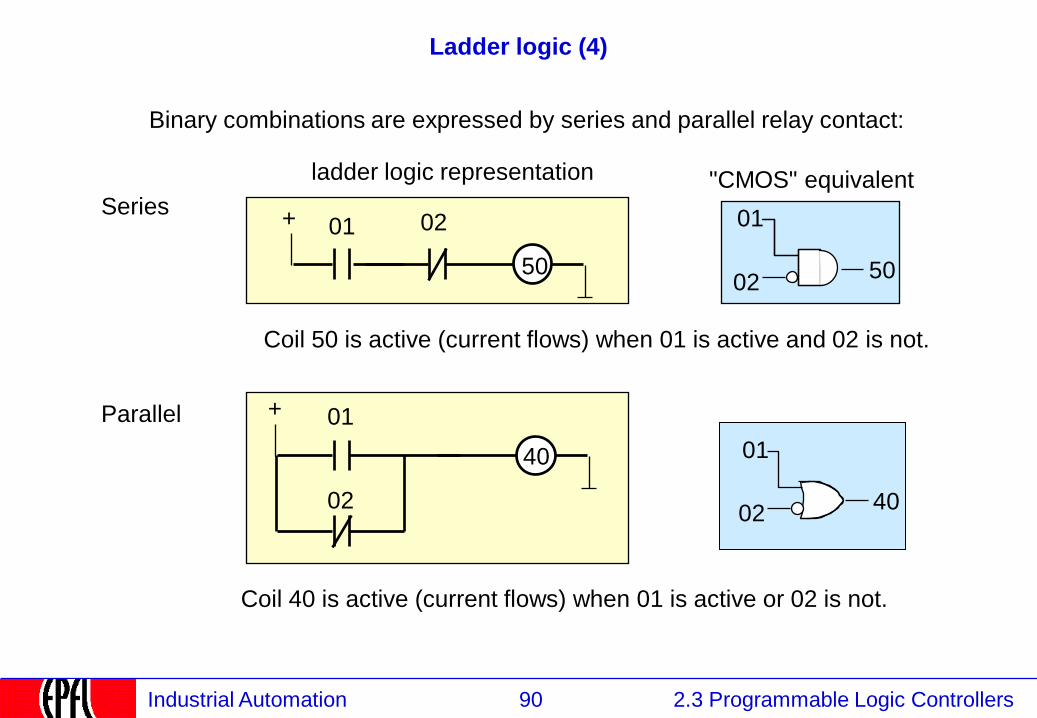
Ladder logic (4)
Binary combinations are expressed by series and parallel relay contact:
+ 01 02
50
Coil 50 is active (current flows) when 01 is active and 02 is not.
01
02 50
Series
+ 01
40
02
Coil 40 is active (current flows) when 01 is active or 02 is not.
Parallel
ladder logic representation "CMOS" equivalent
01
02 40
91 2.3 Programmable Logic Controllers Industrial Automation
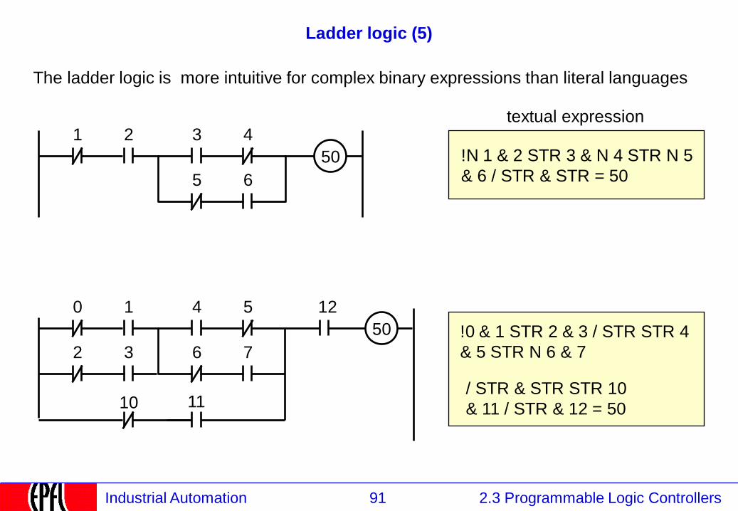
Ladder logic (5)
The ladder logic is more intuitive for complex binary expressions than literal languages
50
1 2 3 4
5 6
!N 1 & 2 STR 3 & N 4 STR N 5
& 6 / STR & STR = 50
50
0 1 4 5
6 7 2 3
10 11
12
!0 & 1 STR 2 & 3 / STR STR 4
& 5 STR N 6 & 7
/ STR & STR STR 10
& 11 / STR & 12 = 50
textual expression
92 2.3 Programmable Logic Controllers Industrial Automation
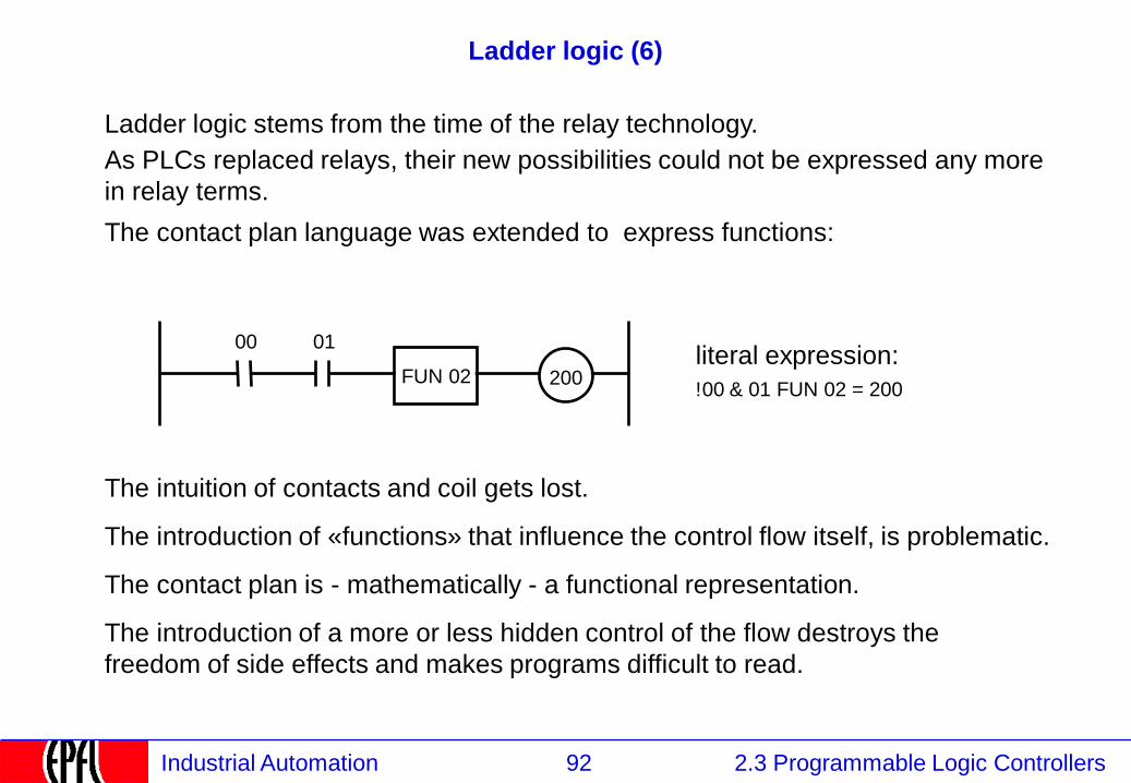
Ladder logic (6)
Ladder logic stems from the time of the relay technology.
As PLCs replaced relays, their new possibilities could not be expressed any more
in relay terms.
The contact plan language was extended to express functions:
literal expression:
!00 & 01 FUN 02 = 200 200 FUN 02
01 00
The intuition of contacts and coil gets lost.
The introduction of «functions» that influence the control flow itself, is problematic.
The contact plan is - mathematically - a functional representation.
The introduction of a more or less hidden control of the flow destroys the
freedom of side effects and makes programs difficult to read.
93 2.3 Programmable Logic Controllers Industrial Automation
Ladder logic (7)
Ladder logic provides neither:
• sub-programs (blocks), nor
• data encapsulation nor
• structured data types.
It is not suited to make reusable modules.
IEC 61131 does not prescribe the minimum requirements for a compiler / interpreter
such as number of rungs per page nor does it specifies the minimum subset to be
implemented.
Therefore, it should not be used for large programs made by different persons
It is very limited when considering analog values (it has only counters)
→ used in manufacturing, not process control

94 2.3 Programmable Logic Controllers Industrial Automation
2.3.6 Instruction Lists
2.1 Instrumentation
2.2 Control
2.3 Programmable Logic Controllers
2.3.1 PLCs: Definition and Market
2.3.2 PLCs: Kinds
2.3.3 PLCs: Functions and construction
2.3.4 Continuous and Discrete Control
2.3.5 PLC Programming Languages
2.3.5.1 IEC 61131 Languages
2.3.5.2 Function blocks
2.3.5.3 Program Execution
2.3.5.4 Input / Output
2.3.5.5 Structured Text
2.3.5.6 Sequential Function Charts
2.3.5.7 Ladder Logic
2.3.5.8 Instructions Lists
2.3.5.9 Programming environment
95 2.3 Programmable Logic Controllers Industrial Automation
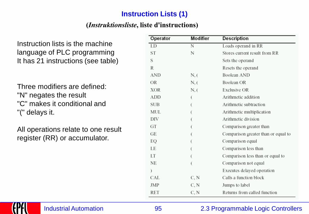
Instruction Lists (1)
Instruction lists is the machine
language of PLC programming
It has 21 instructions (see table)
Three modifiers are defined:
"N" negates the result
"C" makes it conditional and
"(" delays it.
All operations relate to one result
register (RR) or accumulator.
(Instruktionsliste, liste d'instructions)
96 2.3 Programmable Logic Controllers Industrial Automation
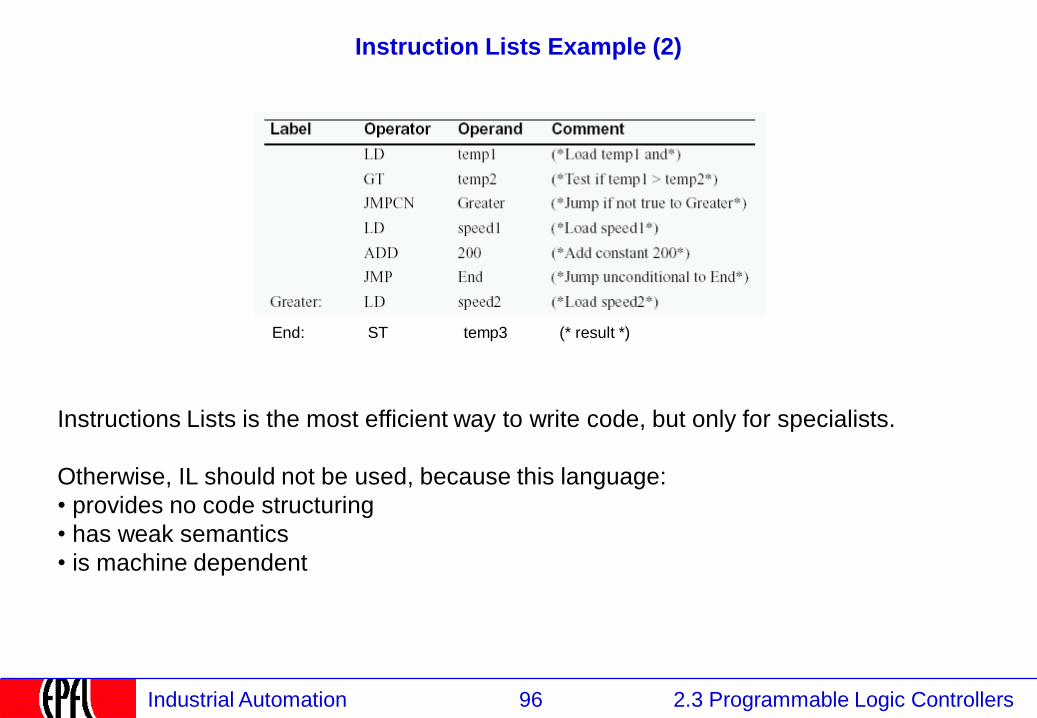
Instruction Lists Example (2)
Instructions Lists is the most efficient way to write code, but only for specialists.
Otherwise, IL should not be used, because this language:
• provides no code structuring
• has weak semantics
• is machine dependent
End: ST temp3 (* result *)
97 2.3 Programmable Logic Controllers Industrial Automation
2.3.5.9 Programming environment
2.1 Instrumentation
2.2 Control
2.3 Programmable Logic Controllers
2.3.1 PLCs: Definition and Market
2.3.2 PLCs: Kinds
2.3.3 PLCs: Functions and construction
2.3.4 Continuous and Discrete Control
2.3.5 PLC Programming Languages
2.3.5.1 IEC 61131 Languages
2.3.5.2 Function blocks
2.3.5.3 Program Execution
2.3.5.4 Input / Output
2.3.5.5 Structured Text
2.3.5.6 Sequential Function Charts
2.3.5.7 Ladder Logic
2.3.5.8 Instructions Lists
2.3.5.9 Programming environment
98 2.3 Programmable Logic Controllers Industrial Automation
Programming environment capabilities
A PLC programming environment (ABB, Siemens, CoDeSys,...) allows:
- programming of the PLC in one of the IEC 61131 languages
- defining the variables (name and type)
- binding of the variables to the input/output (binary, analog)
- simulating
- downloading to the PLC of programs and firmware
- uploading of the PLC (seldom provided)
- monitoring of the PLC
- documenting and printing.
99 2.3 Programmable Logic Controllers Industrial Automation
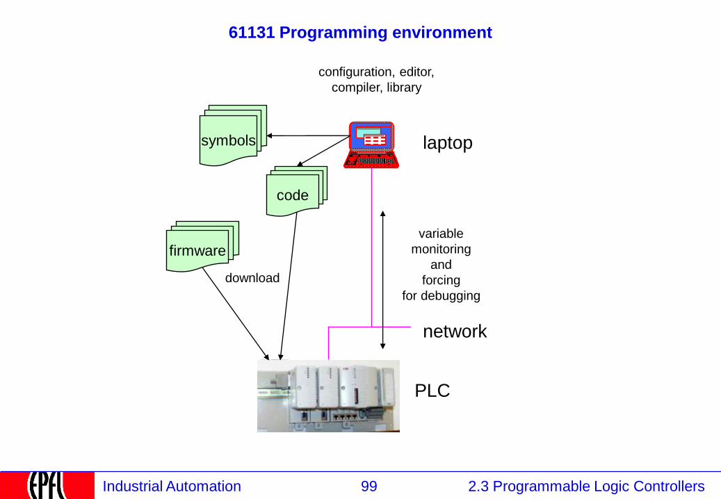
61131 Programming environment
laptop
download
symbols
code
variable
monitoring
and
forcing
for debugging
firmware
network
configuration, editor,
compiler, library
PLC
100 2.3 Programmable Logic Controllers Industrial Automation
Program maintenance
The source of the PLC program is generally on the laptop of the technician.
This copy is frequently modified, it is difficult to track the original in a process database,
especially if several persons work on the same machine.
Therefore, it would be convenient to be able to reconstruct the source programs
out of the PLC's memory (called back-tracking, Rückdokumentation, reconstitution).
This supposes that the instruction lists in the PLC can be mapped directly to graphic
representations -> set of rules how to display the information.
Names of variables, blocks and comments must be kept in clear text, otherwise the code,
although correct, would not be readable.
For cost reasons, this is seldom implemented.
101 2.3 Programmable Logic Controllers Industrial Automation
Is IEC 61131 FB an object-oriented language ?
Not really: it does not support inheritance.
Blocks are not recursive.
But it supports interface definition (typed signals), instantiation, encapsulation, some form of
polymorphism.
Some programming environments offer “control modules” for better object-orientation
102 2.3 Programmable Logic Controllers Industrial Automation
Limitations of IEC 61131
- it is not foreseen to distribute execution of programs over several devices
- event-driven execution is not foreseen. Blocks may be triggered by a Boolean variable,
(but this is good so).
- if structured text increases in importance, better constructs are required (object-oriented)
103 2.3 Programmable Logic Controllers Industrial Automation
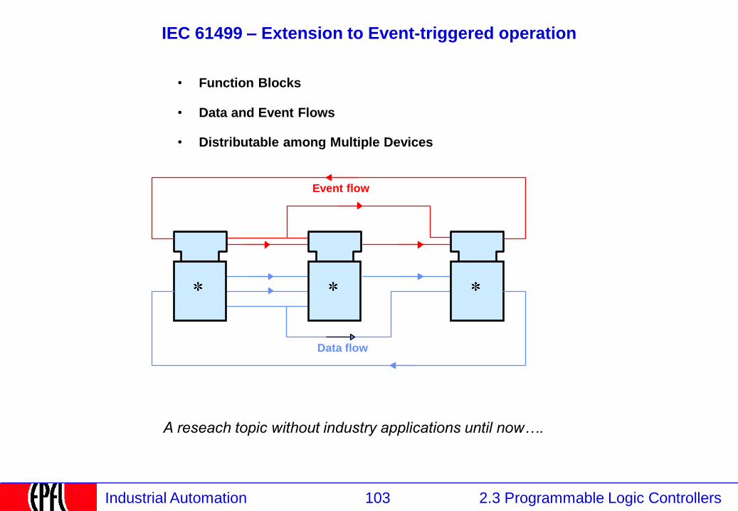
IEC 61499 – Extension to Event-triggered operation
• Function Blocks
• Data and Event Flows
• Distributable among Multiple Devices
Event flow
Data flow
A reseach topic without industry applications until now….
104 2.3 Programmable Logic Controllers Industrial Automation
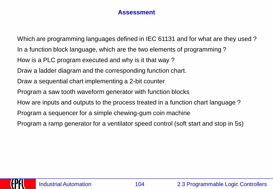
Assessment
Which are programming languages defined in IEC 61131 and for what are they used ?
In a function block language, which are the two elements of programming ?
How is a PLC program executed and why is it that way ?
Draw a ladder diagram and the corresponding function chart.
Draw a sequential chart implementing a 2-bit counter
Program a saw tooth waveform generator with function blocks
How are inputs and outputs to the process treated in a function chart language ?
Program a sequencer for a simple chewing-gum coin machine
Program a ramp generator for a ventilator speed control (soft start and stop in 5s)

106 2.3 Programmable Logic Controllers Industrial Automation
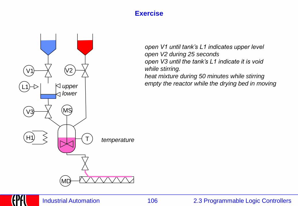
Exercise
L1
T
V1 V2
open V1 until tank’s L1 indicates upper level
open V2 during 25 seconds
open V3 until the tank’s L1 indicate it is void
while stirring.
heat mixture during 50 minutes while stirring
empty the reactor while the drying bed in moving
MS V3
MD
temperature H1
upper
lower