Embed Size (px)
Citation preview
California North Coast Offshore Wind Studies
Subsea Transmission Cable Conceptual Assessment
This report was prepared by Aaron Porter and Shane Phillips of The Mott MacDonald Group. It is part of
the California North Coast Offshore Wind Studies collection, edited by Mark Severy, Zachary Alva,
Gregory Chapman, Maia Cheli, Tanya Garcia, Christina Ortega, Nicole Salas, Amin Younes, James
Zoellick, & Arne Jacobson, and published by the Schatz Energy Research Center in September 2020.
The series is available online at schatzcenter.org/wind/
Schatz Energy Research Center
Humboldt State University
Arcata, CA 95521 | (707) 826-4345
California North Coast Offshore Wind Studies
Subsea Transmission Cable Conceptual Assessment ii
Disclaimer
Study collaboration and funding were provided by the U.S. Department of the
Interior, Bureau of Ocean Energy Management (BOEM), Pacific Regional
Office, Camarillo, CA, under Agreement Number M19AC00005. This report has
been technically reviewed by BOEM, and it has been approved for publication.
The views and conclusions contained in this document are those of the authors
and should not be interpreted as representing the opinions or policies of the U.S.
Government, nor does mention of trade names or commercial products constitute
endorsement or recommendation for use.
This study was prepared under contract with Humboldt State University
Sponsored Programs Foundation with financial support from the Department of
Defense, Office of Economic Adjustment. The content reflects the views of the
Humboldt State University Sponsored Programs Foundation and does not
necessarily reflect the views of the Department of Defense, Office of Economic
Adjustment.
This report was created under grant from the Governor’s Office of Planning and
Research, agreement number: OPR19100
About the Schatz Energy Research Center
The Schatz Energy Research Center at Humboldt State University advances clean
and renewable energy. Our projects aim to reduce climate change and pollution
while increasing energy access and resilience.
Our work is collaborative and multidisciplinary, and we are grateful to the many
partners who together make our efforts possible.
Learn more about our work at schatzcenter.org
Rights and Permissions
The material in this work is subject to copyright. Please cite as follows:
Porter, A., and Phillips, S. (2020). Subsea Transmission Cable Conceptual
Assessment. In M. Severy, Z. Alva, G. Chapman, M. Cheli, T. Garcia, C. Ortega,
N. Salas, A. Younes, J. Zoellick, & A. Jacobson (Eds.) California North Coast
Offshore Wind Studies. Humboldt, CA: Schatz Energy Research Center.
schatzcenter.org/pubs/2020-OSW-R5.pdf.
All images remain the sole property of their source and may not be used for any
purpose without written permission from that source.
Project: Humboldt Offshore Wind
Our reference: 507100657 Subject: Humboldt-SF Bay Subsea Transmission Cable
Prepared by: Aaron Porter, PE Date: 8/28/20
Approved by: Shane Phillips, PE Checked by: Michelle Gostic
Executive Summary
A concept-level assessment was conducted to develop options and document hazards and constraints for
routing a high voltage direct current (HVDC) cable from the Humboldt Bay area to the San Francisco Bay (SF
Bay) area. The transmission cable would be intended to deliver power generated from an offshore wind farm(s)
in the Humboldt area to load centers in the SF Bay area. The subsea transmission cable was assessed in
parallel to upland grid upgrade options. The subsea distance between SF Bay and Humboldt Bay (~250 miles)
necessitates the use of an HVDC electrical system to minimize electrical losses. The HVDC cable system
would consist of the cable system itself and an HVDC converter station at each end of the transmission cable
(Humboldt Area and SF Bay Area) to convert the power to/from the standard alternating current (AC) grid
system.
The subsea study area between Humboldt Bay and SF Bay includes both natural and anthropogenic
constraints and hazards with variable levels of risk. These hazards and constraints will require a combination
of avoidance and mitigation measures to install a transmission cable between the two areas. In summary, the
project risks due to hazards and constraints are the following:
● Hazards
– Deep subsea canyons extending from the nearshore area to depths below the continental shelf, where
subsea landslides strong enough to rupture cables are common.
– Seismic fault line surface displacements which may be too large to mitigate for. Cable repairs may be
required with a major seismic event.
– Some of the largest subsea sandwaves in the world are present outside the Golden Gate, which may
preclude subsea transmission cable routing through the Golden Gate.
● Constraints
– Areas of exposed bedrock and other hard substrate are located within marine habitat areas where cable
protection methods may be either expensive or not permitted by agencies.
– Potential interferences with or damage from fishing activities if the cable is not able to be buried or
otherwise protected
– No power cables have been installed to the depths required to route offshore of the subsea canyons
(over 9,000 feet deep), and proven cable technology has not yet been developed for installation at these
depths.
– The offshore route will likely require crossing telecommunication cables in very deep water (5,000 feet or
greater), which will require permissions from the existing operators. Though telecommunication cables
Technical Memorandum Transmission Cable
California North Coast Offshore Wind Studies
Subsea Transmission Cable Conceptual Assessment 1
crossings at these depths are common, power/telecommunication cable crossings at this depth do not
appear to have previously been attempted.
Based on the location and mitigation possibilities for the hazards and constraints, two potential cable corridors
have been developed: a “Nearshore” corridor, an “Offshore” corridor. Both corridors have significant
challenges that would need to be overcome to install and operate an HVDC link, though the challenges may
not be insurmountable. Further analysis may be conducted to refine the severity of these risks and to develop
possible mitigation strategies.
The construction cost of the system is estimated to be approximately $2.1 – 3.1 billion, depending on whether
one or two cables are installed. It is likely that a single pole pair (one cable bundle) would be able to meet the
rating requirements of 1,800 megawatts (MW). Installing two cables along different routes would provide
redundancy for the transmission system in the case one cable incurs a fault or is damaged but would come at
an additional cost of approximately $1 billion. Should multiple transmission cables be required to support
transmission of multiple offshore windfarms (greater than 1800 megawatts), separation of cable routes should
be considered to reduce risk of cable damage due to the hazards identified.
California North Coast Offshore Wind Studies
Subsea Transmission Cable Conceptual Assessment 2
Executive Summary 1
1 Introduction and Criteria 41.1 Study Criteria 4
2 Existing Conditions 6
3 Assessment 93.1 Electrical Technical Assessment 9
3.1.1 Cable Design 93.1.2 Converter Stations 103.1.3 Potential Spurs to Coastal Towns 12
3.2 Hazard and Constraints Assessment 123.3 Routing Assessment 153.4 Landfall 17
3.4.1 Humboldt Bay 173.4.2 San Francisco Bay 17
3.5 Cost 18
4 Summary 19
References 22
Appendix A 23
Appendix B 24
California North Coast Offshore Wind Studies
Subsea Transmission Cable Conceptual Assessment 3
1 Introduction and Criteria
A pre-feasibility level assessment was conducted to evaluate hazards and constraints, potential cable design
parameters (route and type), and costs of a potential subsea power link between the Humboldt Bay area and
the San Francisco Bay area. The subsea transmission cable was assessed in parallel to upland grid upgrade
options to transmit excess power generated in the region to the load centers in the San Francisco Bay area.
The distance between Humboldt and San Francisco Bay (SF Bay) is approximately 250 miles, and this length
necessities the use of a high-voltage direct current (HVDC) electrical system to minimize electrical losses. A
HVDC cable system would consists of the cable itself, and an HVDC converter station at each end of the cable
(Humboldt Area and SF Bay Area) required to convert power to/from the standard alternating current (AC) grid
system. There are not technical limits to the length of an HVDC system, but at present levels of technology,
HVDC cables can only be deployed as links, rather than a network of HVDC cables. HVDC link systems have
been deployed world-wide for long-distance transmission requirements for solar energy, subsea cables, and
transmitting hydropower energy, with examples on the US West Coast. On the US West Coast the Pacific
Direct Current Intertie was initially constructed by Bonneville Power Administration over a length of 846 miles
to provide lower-cost hydropower energy to the Southern CA region.
The subsea routing assessment was conducted by compiling publicly available data to map potential hazards
and constraints to cable installation and operation in the subsea study area. Within this document, hazards are
defined as an event, process or phenomena which results in a risk of damage to the cable system (such as
fault line displacement). Constraints are defined as established mapped conditions or environmental
conditions, such as marine habitat areas, which need to be addressed as part of the routing assessment. The
mapped hazards and constraints are the basis for the routing assessment. Associated requirements for upland
infrastructure (converter stations) were developed and assessed at a pre-conceptual level.
The project team included experienced submarine cable installers, coastal engineers, and power export cable
design engineers. This memorandum provides study criteria, existing conditions, cable design considerations,
converter station considerations, installation considerations, mapping of mitigation levels required, and two
potential cable route options with a summary of risks and benefits of each.
1.1 Study Criteria
Level of Assessment
This assessment is intended to be conceptual in nature and is based only on review of publicly available data.
No electrical modeling or system studies have been conducted as part of this work. Work conducted was
based on desktop level review only. Findings are intended to be used at a planning-level only and are not
intended to be used for design or other engineering purposes without additional analysis. High-risk areas have
been identified, but detailed investigation of the potential high-risk areas was not conducted.
Electrical Rating requirement
It is assumed that the HVDC link aims to have a rating of approximately 1800MW, but the final rating may be
less, if required based upon results of the assessment.
Routing Assessment Approach
Hazards and constraints should be considered in determination of potential submarine cable routing corridors.
Hazards are not necessarily an obstacle to feasibility, as hazards (such as anchor strike) impose different
ranges of risk, and those hazards can be mitigated to result in a lower risk level, which may be acceptable in
some cases. Similarly, a constraint is not necessarily an obstacle to feasibility, but different constraints (such
California North Coast Offshore Wind Studies
Subsea Transmission Cable Conceptual Assessment 4
as existing telecommunication cables), require different levels of mitigation. This assessment estimated the
likelihood of feasible mitigation measures for the different hazards and constraints. The following classifications
will be utilized to categorize the different hazards and constraints as they relate to mapping:
– No-go area; mitigation of high-risk elements likely not possible.
– Major mitigation; cable installation possible with major mitigation. Major mitigation is intended to
include solutions that require further analysis to develop, necessitate additional coordination and
permissions, are associated with a very high cost, or technology needed is not yet proven.
– Minor mitigation; cable installation possible with minor mitigation. Minor mitigation is intended to
include proven technologies and engineered mitigation measures that are widely applied in industry.
– No mitigation required
Cable routing hazards and constraints in the study region between Humboldt Bay and SF Bay are summarized
in Section 2 and assessed in Section 3.
California North Coast Offshore Wind Studies
Subsea Transmission Cable Conceptual Assessment 5
2 Existing Conditions
Existing conditions were evaluated to develop the hazards and constraints which may affect concept level
routing1, assessment of installation risks, and design of the cable transmission system. Information was
collected from the public domain, and hazard information was also provided by Humboldt State University
(HSU). The potential hazards and constraints are listed in Tables 1 and 2.
These hazards and constraints were mapped to provide a guide to determine which could be avoided or may
require mitigation solutions. To provide a basis for development of concept routes, the applicable hazards and
constraints were mapped in a graphical information system (GIS), as shown in Figure 1. Details, risks and
potential mitigation levels required for the hazards and constraints are addressed in Section 3.3.
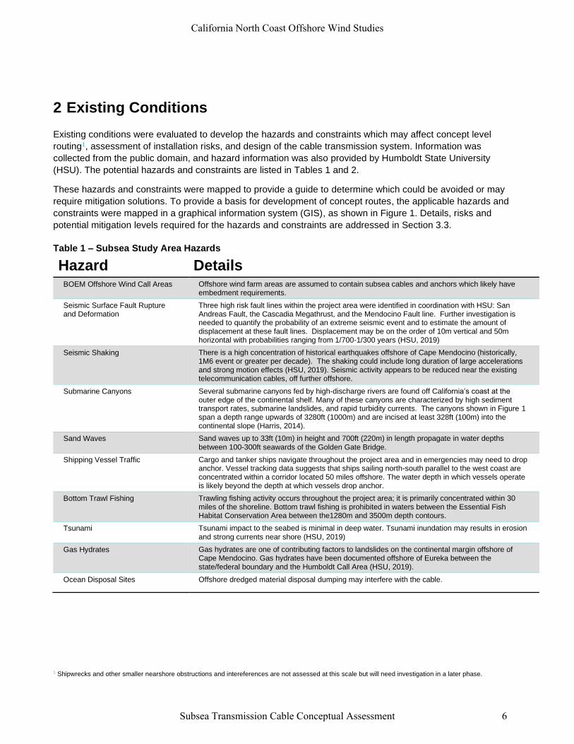
Table 1 – Subsea Study Area Hazards
Hazard Details BOEM Offshore Wind Call Areas Offshore wind farm areas are assumed to contain subsea cables and anchors which likely have
embedment requirements.
Seismic Surface Fault Rupture and Deformation
Three high risk fault lines within the project area were identified in coordination with HSU: San Andreas Fault, the Cascadia Megathrust, and the Mendocino Fault line. Further investigation is needed to quantify the probability of an extreme seismic event and to estimate the amount of displacement at these fault lines. Displacement may be on the order of 10m vertical and 50m horizontal with probabilities ranging from 1/700-1/300 years (HSU, 2019)
Seismic Shaking There is a high concentration of historical earthquakes offshore of Cape Mendocino (historically, 1M6 event or greater per decade). The shaking could include long duration of large accelerations and strong motion effects (HSU, 2019). Seismic activity appears to be reduced near the existing telecommunication cables, off further offshore.
Submarine Canyons Several submarine canyons fed by high-discharge rivers are found off California’s coast at the outer edge of the continental shelf. Many of these canyons are characterized by high sediment transport rates, submarine landslides, and rapid turbidity currents. The canyons shown in Figure 1 span a depth range upwards of 3280ft (1000m) and are incised at least 328ft (100m) into the continental slope (Harris, 2014).
Sand Waves Sand waves up to 33ft (10m) in height and 700ft (220m) in length propagate in water depths between 100-300ft seawards of the Golden Gate Bridge.
Shipping Vessel Traffic Cargo and tanker ships navigate throughout the project area and in emergencies may need to drop anchor. Vessel tracking data suggests that ships sailing north-south parallel to the west coast are concentrated within a corridor located 50 miles offshore. The water depth in which vessels operate is likely beyond the depth at which vessels drop anchor.
Bottom Trawl Fishing Trawling fishing activity occurs throughout the project area; it is primarily concentrated within 30 miles of the shoreline. Bottom trawl fishing is prohibited in waters between the Essential Fish Habitat Conservation Area between the1280m and 3500m depth contours.
Tsunami Tsunami impact to the seabed is minimal in deep water. Tsunami inundation may results in erosion and strong currents near shore (HSU, 2019)
Gas Hydrates Gas hydrates are one of contributing factors to landslides on the continental margin offshore of Cape Mendocino. Gas hydrates have been documented offshore of Eureka between the state/federal boundary and the Humboldt Call Area (HSU, 2019).
Ocean Disposal Sites Offshore dredged material disposal dumping may interfere with the cable.
1 Shipwrecks and other smaller nearshore obstructions and intereferences are not assessed at this scale but will need investigation in a later phase.
California North Coast Offshore Wind Studies
Subsea Transmission Cable Conceptual Assessment 6
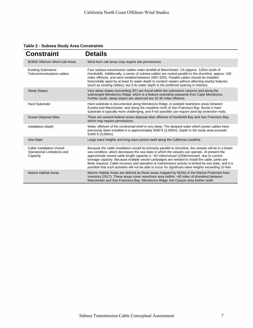
Table 2 - Subsea Study Area Constraints
Constraint Details BOEM Offshore Wind Call Areas Wind farm call areas may require site permissions.
Existing Submarine Telecommunications cables
Four subsea transmission cables make landfall at Manchester, CA (approx. 125mi south of Humboldt). Additionally, a series of subsea cables are routed parallel to the shoreline, approx. 100 miles offshore, and were installed between 1997-2002. Parallel cables should be installed horizontally apart by at least 2x water depth to conduct repairs without affecting nearby features (such as existing cables), but 3-4x water depth is the preferred spacing in industry.
Steep Slopes Very steep slopes (exceeding 30o) are found within the submarine canyons and along the submerged Mendocino Ridge, which is a feature extending seawards from Cape Mendocino. Further south, steep slopes are observed are 10-30 miles offshore.
Hard Substrate Hard substrate is documented along Mendocino Ridge, in isolated nearshore areas between Eureka and Manchester, and along the coastline north of San Francisco Bay. Burial in hard substrate is typically more challenging, and if not possible can require post-lay protection mats.
Ocean Disposal Sites There are several federal ocean disposal sites offshore of Humboldt Bay and San Francisco Bay which may require permissions.
Installation Depth Water offshore of the continental shelf is very deep. The deepest water which power cables have previously been installed in is approximately 6560 ft (2,000m). Depth in the study area exceeds 9,840 ft (3,000m).
Sea-State Large wave heights and long wave period swell along the California coastline
Cable Installation Vessel Operational Limitations and Capacity
Because the cable installation would be primarily parallel to shoreline, the vessels will be in a beam sea condition, which decreases the sea state in which the vessels can operate. At present the approximate vessel cable length capacity is ~62 miles/vessel (100km/vessel) due to current tonnage capacity. Because multiple vessel campaigns are needed to install the cable, joints are likely required. Cable recovery and operation & maintenance activity is limited by sea state, and it is possible that such activities will not be able to occur for significant wave heights exceeding 10 feet
Marine Habitat Areas Marine Habitat Areas are defined as those areas mapped by NOAA in the Marine Protected Area Inventory (2017). These areas cover nearshore area (within ~40 miles of shoreline) between Manchester and San Francisco Bay; Mendocino Ridge; Eel Canyon area further north.
California North Coast Offshore Wind Studies
Subsea Transmission Cable Conceptual Assessment 7
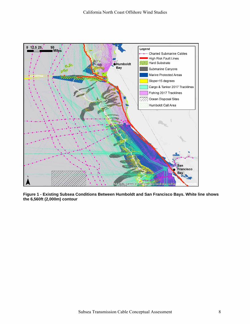
Figure 1 - Existing Subsea Conditions Between Humboldt and San Francisco Bays. White line shows the 6,560ft (2,000m) contour
California North Coast Offshore Wind Studies
Subsea Transmission Cable Conceptual Assessment 8
3 Assessment
An assessment has been conducted to identify potential transmission cable system requirements and to
document the constraints and hazards relative to potential cable routes. This section first includes an
assessment of the cable and converter station components (Section 3.1), key constraints (Section 3.2), and
key hazards (Section 3.3). Based on these inputs a routing risk assessment was conducted (Section 3.4) for
potential nearshore and offshore cable corridors. Potential landfall in the SF Bay area is described in Section
3.4, and an overview of a probable construction cost for the system is provided in Section 3.5.
3.1 Electrical Technical Assessment
3.1.1 Cable Design
Cable design includes consideration of the rating requirements, types, and number of cables/
3.1.1.1 Cable Rating
● Assessment
– Assume 500kV cable. The industry is moving towards this option for multiple cable types and should be
considered within the project timeframe.
3.1.1.2 Cable Types:
The type of cable affects how many cables are required for the potential cable rating.
● MIND
– The highest capacity type of cable is mass-impregnated non-draining (MIND) with Polypropylene Paper
Laminate (PPL) insulation (to +/- 800kV), though the highest present service rating of this type of cable
is +/- 600 kv. With a 4000A converter station, it would be able to be rated up to ~2.4GW for a single pole
pair (cable bundle). The cost of MIND cable is about $800,000 per km of cable supplied
● XLPE
– Extruded cross-linked polyethylene (XPLE) cables are designed for use up to +/- 320kV, though service
experience has shown them up to 400 kV (cable rating of approximately 1.3-1.6 GW per cable). For this
project it is assumed that the cable may be up to 500 kV given the project timeline, which would likely be
able to meet the project rating requirements, depending on landfall details. The cost of XLPE cable is
about $650,000 per km of cable supplied.
● Assessment
– The cable may be XPLE or MIND, but for both cable types there is not a proven technology at 9,840ft+
(3,000m+) water depth.
3.1.1.3 Number of cables
– The number of cables is dependent on water temperature & landfall details.
– Based on a 500kV cable technology being available, 1 pole pair may be possible to meet the rating
requirements but requires further analysis.
– If multiple cable routes are required offshore, further assessment of spacing requirements relative to the
proposed cable alignments and existing constraints needs to be investigated further. Industry standard
offset distance for repair and maintenance is approximately 2-4x water depth, which is needed to safely
California North Coast Offshore Wind Studies
Subsea Transmission Cable Conceptual Assessment 9
bring the cable to the surface, repair the cable, and lay back down on the seabed in accordance with
industry practice. Horizontal offset distances need further investigation at pinch points (such as between
existing subsea cables) to evaluate if two cables can feasibly be installed.
– Details at the SF Bay area interconnection could result in a need to have two 1GW solutions, rather than
a single 1.8GW solution.
● Assessment
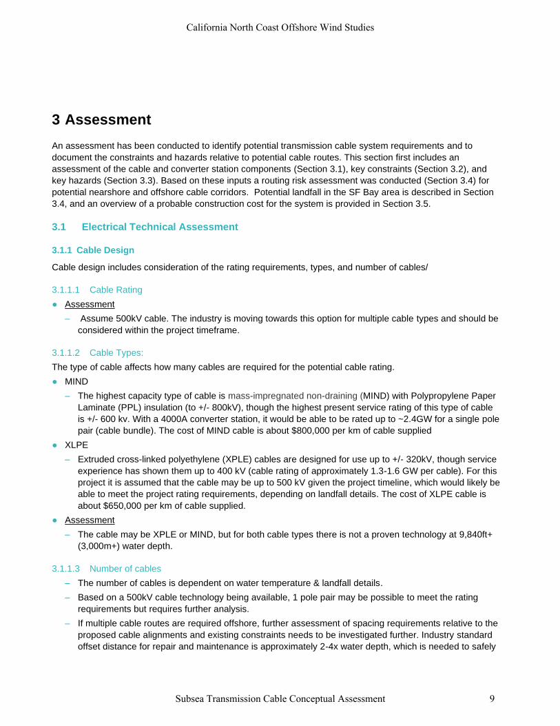
– A single pole pair (single installation) is likely possible, as shown in Figure 2 for an example XPLE pole
pair. A two-cable bundle solution (splitting transmission into two cable routes) would provide additional
resiliency but would result in significantly higher cost, and further analysis is needed to confirm spacing
availability and offshore route feasibility.
3.1.1.4 Cable Design Summary
A single pole pair is likely possible (single installation). XPLE or MIND cable is likely possible to meet rating
requirements, but there is not presently a solution for safe installation at 3,000m water depth. Technology
developments would be required to allow installations at 3,000m and are not yet proven to be feasible.
Figure 2 - Cable Cross-Section Concepts - Bundled XPLE Pole Pair example
3.1.2 Converter Stations
3.1.2.1 Background and Type
– Converter stations are needed to convert AC current to DC, and vice-versa. An HVDC transmission
system requires converter stations at both terminals of the DC link. Converter stations include specialty
electrical equipment such as valves, converter transformers, and filters.
– There are two types of technology available for converter station: Line Commutated Converters (LCC)
and Voltage Sourced Converters (VSC). Both converter station types require multiple acres of land, but
there are some key differences between converter types that are considered for this study, as described
in Table 3.
● Assessment:
– VSC is more likely for this project due to likely space requirements in the SF Bay Area and potential AC
strength issues with any rolling blackouts/brownouts in CA region for LCC converter stations.
California North Coast Offshore Wind Studies
Subsea Transmission Cable Conceptual Assessment 10
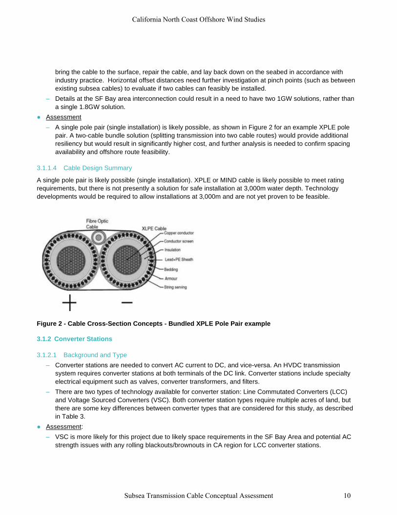
Table 3 – Converter Station Type Summary
LCC VSC ● Compatible with only one type of cable (MIND)
● If AC strength is too low; could lead to instability in the
system. Cannot do a “black-start” requires external power.
● Likely requires space equivalent on the order of 10-20 acres.
● Mature technology
● Compatible with either MIND, or cheaper XPLE cable.
● More expensive, but smaller footprint likely on the order of 5-12 acres
● Does not require external power support
● Newer technology, emerging in the 1980s and 1990s
● At the time of this study there are no active VSC converter stations
operating at the design rating of approximately 1800MW (though there
are others in planning stage).
Figure 3 - Example LCC Converter Station (Western Link, 2200MW)
3.1.2.2 Location
This section provides commentary on siting of an HVDC converter station, whether offshore or onshore.
Onshore
– The converter stations should be designed for seismic considerations and should be sited with regard to
tsunami inundation risk.
● Assessment:
– If in the inundation zone, the converter station may need to include mitigative measures such as a flood
wall or construction on fill.
Offshore
– In general, offshore converter stations are more expensive and complex than converter stations on land.
– At the time of this study there are no existing floating HVDC converter stations, the only offshore
converter stations are affixed to the seabed. However, floating HVDC converter stations may be
California North Coast Offshore Wind Studies
Subsea Transmission Cable Conceptual Assessment 11
developed in the future. The Carbon Trust (2018) undertook a concept assessment for floating offshore
substations, which included California, and found that floating substations in this wave climate are likely
feasible when considering likely floating structure accelerations. However, HVDC converter stations
were not specifically addressed.
– If developed, a floating HVDC converter station will need to accommodate potentially large motions at
Humboldt due to the energetic wave climate.
– If a fixed offshore platform HVDC converter option were installed it would need to be close to the coast
in water depth less than approximately 150 feet, which may not be preferred by stakeholders or
permitting agencies. Two platforms may be required, which would require two cables
– Similar to floating offshore wind, the floating structures would necessitate dynamic cables, designed to
be able to move within the water. At present, there is no HVDC solution for dynamic cables. The cost for
dynamic HVDC cables is likely to be higher as they will likely require copper sheathing.
● Assessment:
– For this study it has been assumed the HVDC converter stations are on land since floating offshore
HVDC converter stations and the associated dynamic HVDC cables have not yet been proven
technology. Secondly, there are limited locations for a shallow-water fixed foundation HVDC converter
station offshore.
3.1.2.3 Converter Station Summary
VSC is more likely for this project due to space requirements and potential issues with blackouts/brownouts in
the CA region for LCC converter stations. A floating HVDC converter station may potentially be developed in
the future, but no existing technology currently exists for the converter station, or the required dynamic HVDC
cables required for interconnection. On-shore converter stations of this magnitude are currently in the planning
stage elsewhere in the world.
3.1.3 Potential Spurs to Coastal Towns
At the request of HSU, the possibility of developing spurs to coastal towns from an offshore HVDC backbone
has been considered. A brief summary of the challenges and opportunities are described below.
● Converter Stations.
– A converter station is required to tap off power to smaller communities along route; ongoing
maintenance of offshore converter station required (expensive), unless routed to shore.
● Cables
– More joints offshore means higher risk for potential damage
● Routing
– If cables are routed onshore, this might provide opportunity for upland routing to avoid canyons/faults.
● Assessment:
– A spur off the main subsea HVDC link would be very expensive solution to deliver a relatively small
amount of power to these communities. This alternative is unlikely to be pursued with existing
technology but may potentially be pursued if the DC link is routed upland for a portion of the route.
3.2 Hazard and Constraints Assessment
An assessment of the hazards and constraints affecting the cable system has been developed relative to the
mitigation and risk criteria listed in Section 1. Results of this assessment are provided in Tables 4 and 5 for
California North Coast Offshore Wind Studies
Subsea Transmission Cable Conceptual Assessment 12
hazards and constraints, respectively. Details for key constraints and hazards affecting the cable routing are
provided in Appendix B.
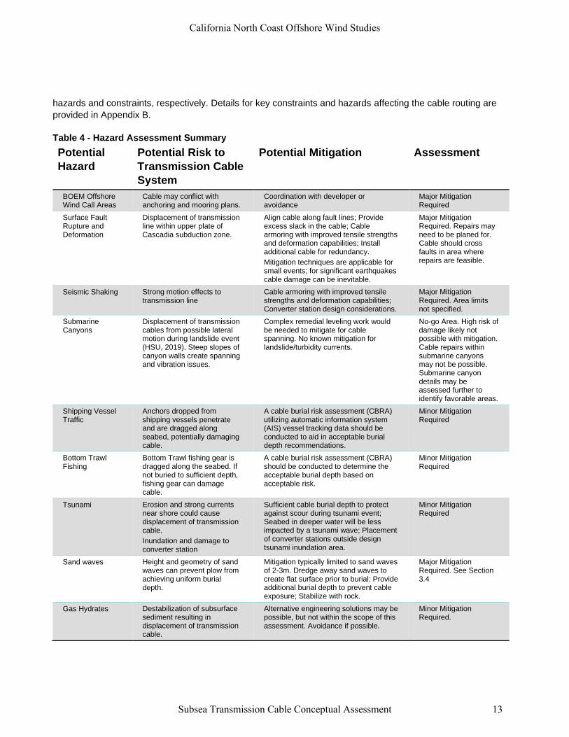
Table 4 - Hazard Assessment Summary
Potential
Hazard
Potential Risk to
Transmission Cable
System
Potential Mitigation Assessment
BOEM Offshore Wind Call Areas
Cable may conflict with anchoring and mooring plans.
Coordination with developer or avoidance
Major Mitigation Required
Surface Fault Rupture and Deformation
Displacement of transmission line within upper plate of Cascadia subduction zone.
Align cable along fault lines; Provide excess slack in the cable; Cable armoring with improved tensile strengths and deformation capabilities; Install additional cable for redundancy.
Mitigation techniques are applicable for small events; for significant earthquakes cable damage can be inevitable.
Major Mitigation Required. Repairs may need to be planed for. Cable should cross faults in area where repairs are feasible.
Seismic Shaking Strong motion effects to transmission line
Cable armoring with improved tensile strengths and deformation capabilities; Converter station design considerations.
Major Mitigation Required. Area limits not specified.
Submarine Canyons
Displacement of transmission cables from possible lateral motion during landslide event (HSU, 2019). Steep slopes of canyon walls create spanning and vibration issues.
Complex remedial leveling work would be needed to mitigate for cable spanning. No known mitigation for landslide/turbidity currents.
No-go Area. High risk of damage likely not possible with mitigation. Cable repairs within submarine canyons may not be possible. Submarine canyon details may be assessed further to identify favorable areas.
Shipping Vessel Traffic
Anchors dropped from shipping vessels penetrate and are dragged along seabed, potentially damaging cable.
A cable burial risk assessment (CBRA) utilizing automatic information system (AIS) vessel tracking data should be conducted to aid in acceptable burial depth recommendations.
Minor Mitigation Required
Bottom Trawl Fishing
Bottom Trawl fishing gear is dragged along the seabed. If not buried to sufficient depth, fishing gear can damage cable.
A cable burial risk assessment (CBRA) should be conducted to determine the acceptable burial depth based on acceptable risk.
Minor Mitigation Required
Tsunami Erosion and strong currents near shore could cause displacement of transmission cable.
Inundation and damage to converter station
Sufficient cable burial depth to protect against scour during tsunami event; Seabed in deeper water will be less impacted by a tsunami wave; Placement of converter stations outside design tsunami inundation area.
Minor Mitigation Required
Sand waves Height and geometry of sand waves can prevent plow from achieving uniform burial depth.
Mitigation typically limited to sand waves of 2-3m. Dredge away sand waves to create flat surface prior to burial; Provide additional burial depth to prevent cable exposure; Stabilize with rock.
Major Mitigation Required. See Section 3.4
Gas Hydrates Destabilization of subsurface sediment resulting in displacement of transmission cable.
Alternative engineering solutions may be possible, but not within the scope of this assessment. Avoidance if possible.
Minor Mitigation Required.
California North Coast Offshore Wind Studies
Subsea Transmission Cable Conceptual Assessment 13
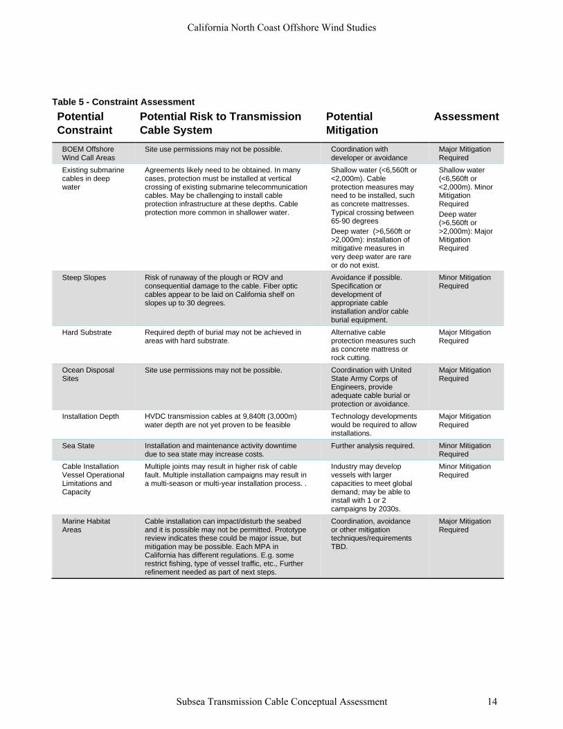
Table 5 - Constraint Assessment
Potential
Constraint
Potential Risk to Transmission
Cable System
Potential
Mitigation
Assessment
BOEM Offshore Wind Call Areas
Site use permissions may not be possible. Coordination with developer or avoidance
Major Mitigation Required
Existing submarine cables in deep water
Agreements likely need to be obtained. In many cases, protection must be installed at vertical crossing of existing submarine telecommunication cables. May be challenging to install cable protection infrastructure at these depths. Cable protection more common in shallower water.
Shallow water (<6,560ft or <2,000m). Cable protection measures may need to be installed, such as concrete mattresses. Typical crossing between 65-90 degrees
Deep water (>6,560ft or>2,000m): installation ofmitigative measures invery deep water are rareor do not exist.
Shallow water (<6,560ft or <2,000m). Minor Mitigation Required
Deep water (>6,560ft or >2,000m): MajorMitigationRequired
Steep Slopes Risk of runaway of the plough or ROV and consequential damage to the cable. Fiber optic cables appear to be laid on California shelf on slopes up to 30 degrees.
Avoidance if possible. Specification or development of appropriate cable installation and/or cable burial equipment.
Minor Mitigation Required
Hard Substrate Required depth of burial may not be achieved in areas with hard substrate.
Alternative cable protection measures such as concrete mattress or rock cutting.
Major Mitigation Required
Ocean Disposal Sites
Site use permissions may not be possible. Coordination with United State Army Corps of Engineers, provide adequate cable burial or protection or avoidance.
Major Mitigation Required
Installation Depth HVDC transmission cables at 9,840ft (3,000m) water depth are not yet proven to be feasible
Technology developments would be required to allow installations.
Major Mitigation Required
Sea State Installation and maintenance activity downtime due to sea state may increase costs.
Further analysis required. Minor Mitigation Required
Cable Installation Vessel Operational Limitations and Capacity
Multiple joints may result in higher risk of cable fault. Multiple installation campaigns may result in a multi-season or multi-year installation process. .
Industry may develop vessels with larger capacities to meet global demand; may be able to install with 1 or 2 campaigns by 2030s.
Minor Mitigation Required
Marine Habitat Areas
Cable installation can impact/disturb the seabed and it is possible may not be permitted. Prototype review indicates these could be major issue, but mitigation may be possible. Each MPA in California has different regulations. E.g. some restrict fishing, type of vessel traffic, etc., Further refinement needed as part of next steps.
Coordination, avoidance or other mitigation techniques/requirements TBD.
Major Mitigation Required
California North Coast Offshore Wind Studies
Subsea Transmission Cable Conceptual Assessment 14
3.3 Routing Assessment
Results of the hazard and constraint assessment have been applied to the available data layers for each
hazard and constraint. The hazards and constraints which geographic data was available for are summarized
in Table 62. Based on the assessment in Section 3.2 a suitability map was generated by assigning the
classifications for the compiled GIS data layers (Figure 4). Converter stations were not assessed as part of the
routing assessment since they are assumed to be located on land. As part of this study, Mott MacDonald was
scoped with developing offshore and onshore corridors for assessment. Potential cable corridors were
developed based on hazard and constraints mapping, and in coordination with technical experts during a multi-
disciplinary team workshop (shown in Figure 4). Two potential cable corridors were developed based on
concept-level avoidance of the mapped constraints and are summarized in Table 7.
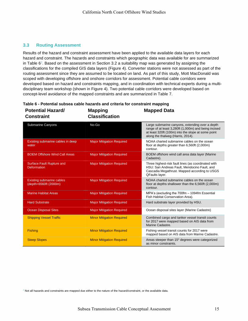
Table 6 - Potential subsea cable hazards and criteria for constraint mapping
Potential Hazard/
Constraint
Mapping
Classification
Mapped Data
Submarine Canyons No-Go Large submarine canyons, extending over a depth range of at least 3,280ft (1,000m) and being incised at least 320ft (100m) into the slope at some point along the thalweg (Harris, 2014).
Existing submarine cables in deep water
Major Mitigation Required NOAA charted submarine cables on the ocean floor at depths greater than 6,560ft (2,000m) contour.
BOEM Offshore Wind Call Areas Major Mitigation Required BOEM offshore wind call area data layer (Marine Cadastre).
Surface Fault Rupture and Deformation
Major Mitigation Required Three highest-risk fault lines (as coordinated with HSU: San Andreas Fault, Mendocino Fault, and Cascadia Megathrust. Mapped according to USGS QFaults layer.
Existing submarine cables (depth<6560ft (2000m)
Major Mitigation Required NOAA charted submarine cables on the ocean floor at depths shallower than the 6,560ft (2,000m) contour.
Marine Habitat Areas Major Mitigation Required MPA’s (excluding the 700fm – 1094fm Essential Fish Habitat Conservation Area).
Hard Substrate Major Mitigation Required Hard substrate layer provided by HSU.
Ocean Disposal Sites Major Mitigation Required Ocean disposal sites layer (Marine Cadastre)
Shipping Vessel Traffic Minor Mitigation Required Combined cargo and tanker vessel transit counts for 2017 were mapped based on AIS data from Marine Cadastre.
Fishing Minor Mitigation Required Fishing vessel transit counts for 2017 were mapped based on AIS data from Marine Cadastre.
Steep Slopes Minor Mitigation Required Areas steeper than 15o degrees were categorized as minor constraints.
2 Not all hazards and constraints are mapped due either to the nature of the hazard/constraint, or the available data.
California North Coast Offshore Wind Studies
Subsea Transmission Cable Conceptual Assessment 15
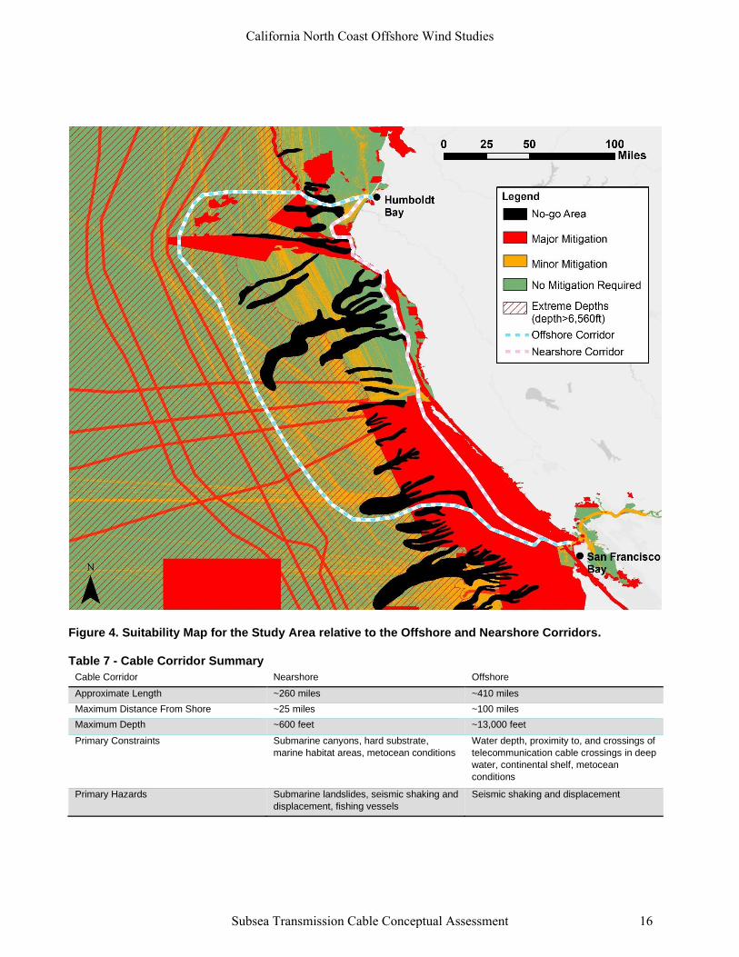
Figure 4. Suitability Map for the Study Area relative to the Offshore and Nearshore Corridors.
Table 7 - Cable Corridor Summary
Cable Corridor Nearshore Offshore
Approximate Length ~260 miles ~410 miles
Maximum Distance From Shore ~25 miles ~100 miles
Maximum Depth ~600 feet ~13,000 feet
Primary Constraints Submarine canyons, hard substrate,
marine habitat areas, metocean conditions
Water depth, proximity to, and crossings of
telecommunication cable crossings in deep
water, continental shelf, metocean
conditions
Primary Hazards Submarine landslides, seismic shaking and
displacement, fishing vessels
Seismic shaking and displacement
California North Coast Offshore Wind Studies
Subsea Transmission Cable Conceptual Assessment 16
3.4 Landfall
Potential landfall at the Humboldt Bay and SF Bay termini of the HVDC cable were assessed at a pre-
conceptual level, and results of the assessment are provided below.
3.4.1 Humboldt Bay
Landfall at Humboldt is anticipated to be similar to the landfall methodologies outlined in the Humboldt Cable
Landfall Memorandum (MM, 2020), with the cable making landfall on a sandy beach.
● Assessment: The likely methodology for landfall is horizontal directional drill (HDD) on the South or North
Spit, with a secondary HDD to cross the bay and be routed to the selected converter station site, depending
on landfall location. HDD feasibility is dependent on geotechnical investigations, and size of the cable
bundle, and requires further analysis.
3.4.2 San Francisco Bay
HSU requested MM to investigate the possibility of routing the HVDC cable to a location within SF Bay.
Landfall and nearshore routing in this area are more complex than landfall in the Humboldt Area. No cables
presently are routed through the Golden Gate. A number of different challenges were identified:
● Presence of large sandwaves in the Golden Gate (e.g., Figure 5)
● A majority of the shoreline north and south of the Golden Gate consists of steep bluffs and cliffs
● Marine Sanctuary
● High volume of vessel traffic
● Multiple cable crossings appear to be required.
A number of the complexities may be able to be mitigated with appropriate engineering operational
permissions, but there are a number of complexities which may preclude routing through the Golden Gate. The
presence of sandwaves is typically mitigated by dredging and flattening the area in which the cable will be
buried to the same level of the trough of the sandwave. However, CSA Ocean Sciences Inc. (2019) reports this
may not be an economical solution for sandwaves with a height of 7-22 feet (2-3 meters). The sandwave
height in the Golden Gate are some of the largest in the world (Barnard et al, 2006), reported to be on the
order of 30ft (9m). Additionally, in order to conduct repairs in this area, dredging would be required to retrieve
the cable for repair, or a new cable would be required.
● Assessment: Further analysis required to assess feasibility of routing subsea cable through the Golden
Gate, whether around or through the sandwave areas, but at this level of assessment the option appears
unfavorable.
California North Coast Offshore Wind Studies
Subsea Transmission Cable Conceptual Assessment 17
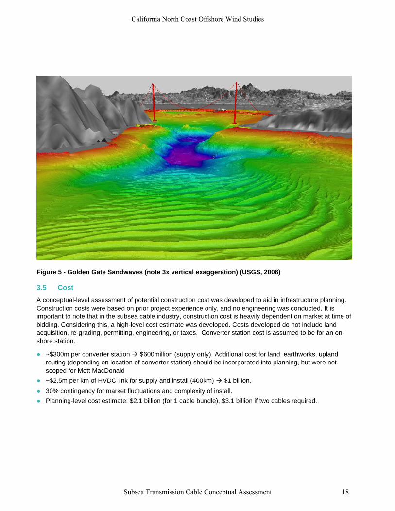
Figure 5 - Golden Gate Sandwaves (note 3x vertical exaggeration) (USGS, 2006)
3.5 Cost
A conceptual-level assessment of potential construction cost was developed to aid in infrastructure planning.
Construction costs were based on prior project experience only, and no engineering was conducted. It is
important to note that in the subsea cable industry, construction cost is heavily dependent on market at time of
bidding. Considering this, a high-level cost estimate was developed. Costs developed do not include land
acquisition, re-grading, permitting, engineering, or taxes. Converter station cost is assumed to be for an on-
shore station.
● ~$300m per converter station → $600million (supply only). Additional cost for land, earthworks, upland
routing (depending on location of converter station) should be incorporated into planning, but were not
scoped for Mott MacDonald
● ~$2.5m per km of HVDC link for supply and install (400km) → $1 billion.
● 30% contingency for market fluctuations and complexity of install.
● Planning-level cost estimate: $2.1 billion (for 1 cable bundle), $3.1 billion if two cables required.
California North Coast Offshore Wind Studies
Subsea Transmission Cable Conceptual Assessment 18
4 Summary
A concept-level assessment was conducted to develop options and documents risks and challenges for a high
voltage direct current (HVDC) cable from the Humboldt Bay area to the San Francisco Bay (SF Bay) area for
the 1,836 MW scenario. The HVDC cable system would consist of the cable system itself and an HVDC
converter station at each end of the cable (Humboldt Area and SF Bay Area).
The construction cost of the system is estimated to be approximately $2.1 – 3.1 billion (based on the
nearshore route length), depending on whether one or two cables are installed. It is likely that a single pole pair
would be able to meet the rating requirements of 1800 megawatts (MW). Installing two cables along different
routes would provide redundancy for the system in case one cable incurs a fault, but would come at an
additional cost of approximately $1 billion.
The subsea study area between Humboldt Bay and San Francisco Bay includes both natural and
anthropogenic constraints and hazards with variable levels of risk. These hazards and constraints will require a
combination of avoidance and mitigation measures in order to install a transmission cable between the two
areas. The primary risks include:
● Hazards
– Deep subsea canyons extending from the nearshore area to depths below the continental shelf, where
subsea landslides strong enough to rupture cables are common.
– Seismic fault line surface displacements which may be too large to mitigate for. Cable repairs may need
to be expected to be conducted with a major seismic event.
– Some of the largest subsea sandwaves in the world are present outside the Golden Gate, which may
preclude subsea transmission cable routing through the Golden Gate.
● Constraints
– Areas of exposed bedrock and other hard substrate are located within marine habitat areas where cable
protection methods may be either expensive or not permitted by agencies.
– Potential interferences with fishing activities if the cable is not able to be buried or otherwise protected
– No power cables have been installed to the depths required to route offshore of the subsea canyons
(over 9,000 feet deep), and proven cable technology has not yet been developed for installation at these
depths.
– The offshore route will likely require crossing telecommunication cables in very deep water (5,000 feet or
greater), which will require permissions from the existing operators. Though telecommunication cables
crossings at these depths are common, power/telecommunication cable crossings at this depth do not
appear to have previously been attempted.
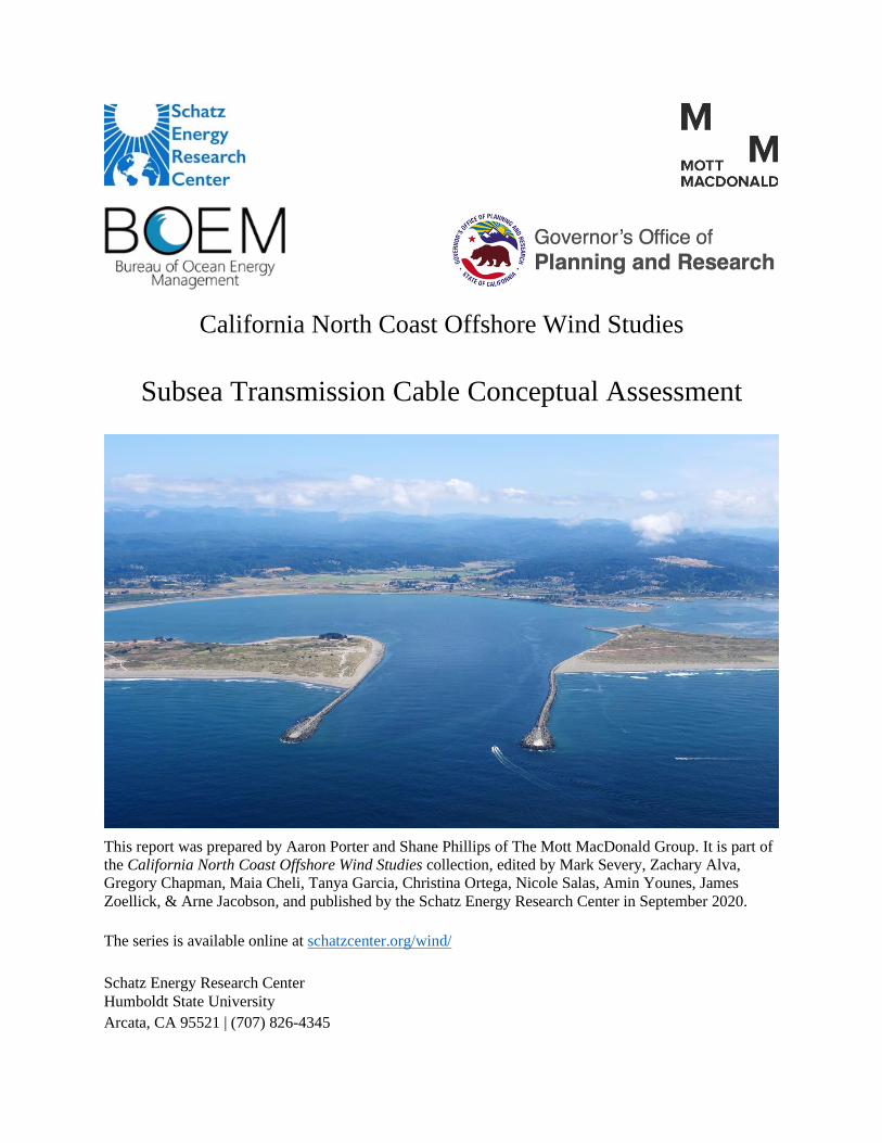
Due to the location and severity of the constraints and hazards, two potential cable corridors have been
developed, a “Nearshore” corridor, an “Offshore” corridor (Figure 6). Both corridors have significant challenges
that would need to be overcome to install and operate an HVDC link, though the challenges may not be
infeasible. A risk/benefit table has been developed for these corridors based on the results of the hazards and
constraints assessment in Table 8.
California North Coast Offshore Wind Studies
Subsea Transmission Cable Conceptual Assessment 19
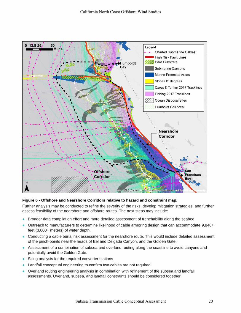
Figure 6 - Offshore and Nearshore Corridors relative to hazard and constraint map.
Further analysis may be conducted to refine the severity of the risks, develop mitigation strategies, and further
assess feasibility of the nearshore and offshore routes. The next steps may include:
● Broader data compilation effort and more detailed assessment of trenchability along the seabed
● Outreach to manufacturers to determine likelihood of cable armoring design that can accommodate 9,840+
feet (3,000+ meters) of water depth.
● Conducting a cable burial risk assessment for the nearshore route. This would include detailed assessment
of the pinch-points near the heads of Eel and Delgada Canyon, and the Golden Gate.
● Assessment of a combination of subsea and overland routing along the coastline to avoid canyons and
potentially avoid the Golden Gate.
● Siting analysis for the required converter stations
● Landfall conceptual engineering to confirm two cables are not required.
● Overland routing engineering analysis in combination with refinement of the subsea and landfall
assessments. Overland, subsea, and landfall constraints should be considered together.
Offshore
Corridor
Corridor
Nearshore
Corridor
Corridor
California North Coast Offshore Wind Studies
Subsea Transmission Cable Conceptual Assessment 20
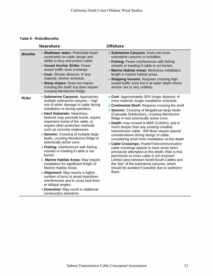
Table 8 - Risks/Benefits
Nearshore Offshore
Benefits ● Shallower water: Potentially fewerconstraints on cable design andability to bury and protect cable.
● Vessel Anchor Strike: Fewervessel traffic zone crossings
● Cost: Shorter distance → lessmaterial, shorter schedule.
● Steep slopes: Does not requirecrossing the shelf, but does requirecrossing Mendocino Ridge
● Submarine Canyons: Does not crosssubmarine canyons or turbidites.
● Fishing: Fewer interferences with fishingvessels or trawling if cable is not buried.
● Marine Habitat Areas: Minimizes installationlength in marine habitat areas.
● Shipping Vessels: Requires crossing highvessel traffic zone but is at water depth whereanchor use is very unlikely.
Risks ● Submarine Canyons: Approachesmultiple submarine canyons – highrisk of either damage to cable duringinstallation or during operation.
● Hard Substrate: Nearshorebedrock may preclude burial, requireexpensive burial of the cable, orrequire other protection methodssuch as concrete mattresses.
● Seismic: Crossing of multiple largefaults, crossing Mendocino Ridge inseismically active zone.
● Fishing: Interferences with fishingvessels or trawling if cable is notburied.
● Marine Habitat Areas: May requireinstallation for significant length ofMarine Habitat Areas.
● Alignment: May require a highernumber of turns to avoid nearshoreinterferences and to cross fault linesat oblique angles..
● Downtime: May result in additionalconstruction downtime
● Cost: Approximately 30% longer distance →more material, longer installation schedule.
● Continental Shelf: Requires crossing the shelf
● Seismic: Crossing of Megathrust large faults(Cascadia Subduction), crossing MendocinoRidge in less seismically active zone.
● Depth: may exceed 9,480ft (3,000m), and ismuch deeper than any existing installedtransmission cable. Will likely require specialconsiderations during design of cable,considering strain from installation at this depth.
● Cable Crossings: Power/Telecommunicationcable crossings appear to have never beenpreviously attempted at this depth. Risk is thatpermission to cross cable is not received.Limited area between North/South Cables andthe “toe” of the submarine canyons, whichshould be avoided if possible due to sedimentflows.
California North Coast Offshore Wind Studies
Subsea Transmission Cable Conceptual Assessment 21
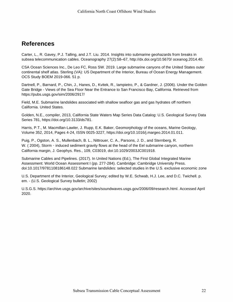
References
Carter, L., R. Gavey, P.J. Talling, and J.T. Liu. 2014. Insights into submarine geohazards from breaks in
subsea telecommunication cables. Oceanography 27(2):58–67, http://dx.doi.org/10.5670/ oceanog.2014.40.
CSA Ocean Sciences Inc., De Leo FC, Ross SW. 2019. Large submarine canyons of the United States outer
continental shelf atlas. Sterling (VA): US Department of the Interior, Bureau of Ocean Energy Management.
OCS Study BOEM 2019-066. 51 p.
Dartnell, P., Barnard, P., Chin, J., Hanes, D., Kvitek, R., Iampietro, P., & Gardner, J. (2006). Under the Golden
Gate Bridge - Views of the Sea Floor Near the Entrance to San Francisco Bay, California. Retrieved from
https://pubs.usgs.gov/sim/2006/2917/
Field, M.E. Submarine landslides associated with shallow seafloor gas and gas hydrates off northern
California. United States.
Golden, N.E., compiler, 2013, California State Waters Map Series Data Catalog: U.S. Geological Survey Data
Series 781, https://doi.org/10.3133/ds781.
Harris, P.T., M. Macmillan-Lawler, J. Rupp, E.K. Baker, Geomorphology of the oceans, Marine Geology,
Volume 352, 2014, Pages 4-24, ISSN 0025-3227, https://doi.org/10.1016/j.margeo.2014.01.011.
Puig, P., Ogston, A. S., Mullenbach, B. L., Nittrouer, C. A., Parsons, J. D., and Sternberg, R.
W. ( 2004), Storm‐induced sediment gravity flows at the head of the Eel submarine canyon, northern
California margin, J. Geophys. Res., 109, C03019, doi:10.1029/2003JC001918.
Submarine Cables and Pipelines. (2017). In United Nations (Ed.), The First Global Integrated Marine
Assessment: World Ocean Assessment I (pp. 277-284). Cambridge: Cambridge University Press.
doi:10.1017/9781108186148.022 Submarine landslides: selected studies in the U.S. exclusive economic zone
U.S. Department of the Interior, Geological Survey; edited by W.E. Schwab, H.J. Lee, and D.C. Twichell. p.
em. - (U.S. Geological Survey bulletin; 2002)
U.S.G.S. https://archive.usgs.gov/archive/sites/soundwaves.usgs.gov/2006/09/research.html. Accessed April
2020.
California North Coast Offshore Wind Studies
Subsea Transmission Cable Conceptual Assessment 22
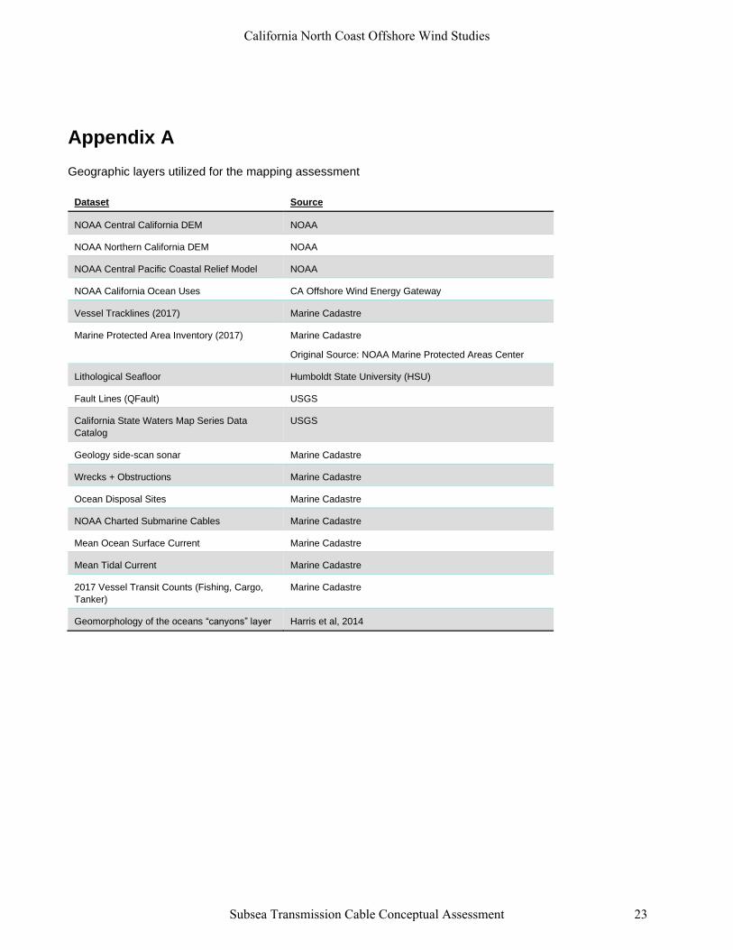
Appendix A
Geographic layers utilized for the mapping assessment
Dataset Source
NOAA Central California DEM NOAA
NOAA Northern California DEM NOAA
NOAA Central Pacific Coastal Relief Model NOAA
NOAA California Ocean Uses CA Offshore Wind Energy Gateway
Vessel Tracklines (2017) Marine Cadastre
Marine Protected Area Inventory (2017) Marine Cadastre
Original Source: NOAA Marine Protected Areas Center
Lithological Seafloor Humboldt State University (HSU)
Fault Lines (QFault) USGS
California State Waters Map Series Data
Catalog
USGS
Geology side-scan sonar Marine Cadastre
Wrecks + Obstructions Marine Cadastre
Ocean Disposal Sites Marine Cadastre
NOAA Charted Submarine Cables Marine Cadastre
Mean Ocean Surface Current Marine Cadastre
Mean Tidal Current Marine Cadastre
2017 Vessel Transit Counts (Fishing, Cargo,
Tanker)
Marine Cadastre
Geomorphology of the oceans “canyons” layer Harris et al, 2014
California North Coast Offshore Wind Studies
Subsea Transmission Cable Conceptual Assessment 23
Appendix B – Hazard and Constraints Assessment Details
Hazard Assessment
Submarine Canyons
● The most common faults in deep water are submarine landslides and associated turbidity currents. Where
possible, cable route planners avoid zones of active landslides and turbidity currents such as submarine
canyons and channels, but this is not always possible (Source: International Cable Protection Committee)
● CSA Ocean Sciences Inc . (2019) has mapped subsea canyons in the study area. Of the major canyons,
Eel Canyon and Delgada Canyon are both mapped within 1-3km of the shoreline. Harris (2014) has
mapped additional canyons, which have been included in this analysis.
● Puig et al (2004) has identified periodic storm-induced sediment gravity flows at head of Eel Canyon.
● The continental margin off Cape Mendocino contains more submarine landslides than any other region
along west coast of US. One of more prominent slides is Humboldt slide zone, west of Eureka 250-500m
water depths. (Field, 1990).
● Submarine Cables and Pipelines (2017) has identified landslides and turbidity currents caused by seismic
activity in Taiwan. The events identified travelled over 300 kilometers and caused 19 breaks in 7 different
cable systems. The cable repairs works required 11 different vessels which disrupted internet connections
for China, Japan, The Philippines, Singapore, and Vietnam.
● CSA Ocean Sciences Inc. (2019) notes the following with regards to the Taiwan event: “Each of submarine
cable failures to date: less robust telecom failures, not buried, in deep water, or had been laid in mudslide
area down slope of continental shelf”.
● Carter et al (2014) summaries the following w/regards to submarine canyons
– 2006 Taiwan earthquake triggered instantaneous breakage of cables due to sediment density flows
– Key lesson: avoid, where possible, submarine canyons, especially those fed by high discharge rivers.
– Frequency of sediment density flows is a consideration – crossing a system with a probability of
1x/century may be acceptable.
Seismic Activity
● The HVDC cable will need to cross multiple fault lines, with varying risk of a seismic event and surface
displacement. For this study, the focus was on the major fault lines.
● Seismic risk is a significant consideration for cable maintenance risk. For example half of all trans-pacific
cables were damaged due to 2011 Japan Earthquake.
● BOEM recommends to avoid direct fault areas where large displacements occur.
● Some mitigation techniques exist, but its unlikely that all risk from seismic activity can be mitigated.
● Both CSA Ocean Sciences Inc. (CSA Ocean Sciences Inc., 2019) and the California Public Utility
Commission (CPUS, 2014) have issued reports recommending that additional cable slack be incorporated
in fault areas where displacements could occur. Additionally, crossing the fault line at an oblique angle and
improved cable tensile strength may provide some resilience. However, there is likely no reasonable
mitigations available, and some level of repairs should be expected due to displacement.
● The need for planning for seismic risk will likely be a function of the likelihood of occurrence relative to the
design life of the cable.
California North Coast Offshore Wind Studies
Subsea Transmission Cable Conceptual Assessment 24
● Fault lines will need to be crossed, and depending on the severity of the vent, no mitigation may be able to
preclude damage. Therefore, the cable should be routed through areas where maintenance activities can
be safely carried out. Additionally, avoiding the downslope area of a subsea canyon may reduce risk. Fault
crossings and cable route requires further geologic investigation to quantify risk. A secondary cable,
crossing different fault lines, could provide resilience against a major seismic event.
Constraints Assessment
Installation Depth
● Given the current status of existing HVDC cable technology, it is installation of the HVDC cable in water
deeper than 1600m would likely incur significant risk due to the levels of lay strain and water pressures at
such depths.
● High-risk to plan for HVDC cable installation in very deep (1600m+ water depth), but should not be
precluded from possibility.
Installation Vessels
● At present the approximate vessel cable length capacity is ~100km/vessel (current tonnage capacity).
Therefore, multiple vessel campaigns would likely be required with the existing vessel fleet.
● Industry may develop vessels with larger capacities to meet global demand; may be able to install with 1 or
2 campaigns by 2030s.
● To reduce installation timeline, it may be possible to have multiple vessels installing in parallel.
Open Ocean Operations and Wave Climate
● Because joints are likely required between the multiple vessel campaigns needed to install the cable,
further assessment needed to assess downtime during this process.
● The jointing process is similar in deep/shallow water, but additional time and complexity is present in deep-
water locations to bring up the cable from large depths.
● During jointing operations the vessel needs to be stable (e.g. requiring calm seas) for long period of time (3-
5 days), which may be difficult in the Pacific.
● Because the cable installation would be primarily parallel to shoreline, the vessels will be dealing with beam
seas, which decreases the sea state in which the vessels can operate (more downtime).
● Barge installations in shallower water are typically more weather dependent due to the type of equipment
used.
● There is likely to be downtime for cable installation vessels/barges in the study area more so for near-shore
areas. Additional assessment may be required to confirm weather window availability for jointing
operations.
Maintenance
● According to the International Cable Protection Committee:
– Worldwide there are approximately 150-200 subsea cable faults per year, due to a number of different
causes.
– 60-70% of faults are due to fishing and shipping occurring in shallow (<600 feet) water.
– Less than 10% of faults are caused by natural hazards, but do occur in deep water.
California North Coast Offshore Wind Studies
Subsea Transmission Cable Conceptual Assessment 25
● Cable recovery and operation & maintenance activity is limited by sea state. It is possible that such
activities will not be able to occur for significant wave heights exceeding 10 feet (3m). During these
operations the vessel needs to be stable for long period of time (3-5 days), which may be difficult in this
area of the Pacific in winter conditions. Repairs may be limited to summer seasons.
● Requires cable installation spacing of typically at least 2x water depth to conduct repairs without affecting
nearby features (such as existing cables). 3-4x water depth is preferred spacing.
● Maintenance takes longer offshore than in nearshore due to deeper water and complexity of operations.
● Certified, trained jointers need to be available to maintain the cable warranty.
● Maintenance planning should be conducted. There may be significant downtime should a cable fault occur,
between the time of the fault, and repairs being conducted. Appropriate vessels will need to be mobilized
with trained crew, and repairs to power cables have never before been conducted for the depths along
portions of the study area.
Telecommunication Cable Crossings
● Permissions will likely be needed to cross existing telecommunications cables. In shallow-water
applications the risks of export cables crossing telecommunication cables are mitigated by engineering
appropriate protection measures, such as a concrete marine mattress or other. Telecommunication cables
also cross one another in deep water, but the permission risk for a high-voltage cable crossing an existing
telecommunications cable may be more challenging.
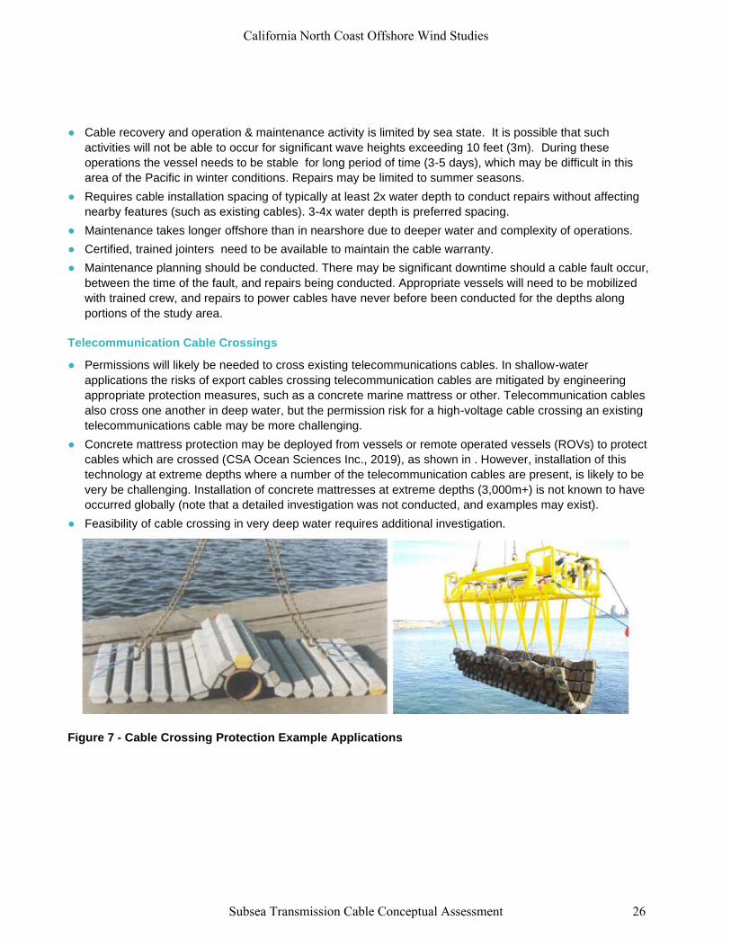
● Concrete mattress protection may be deployed from vessels or remote operated vessels (ROVs) to protect
cables which are crossed (CSA Ocean Sciences Inc., 2019), as shown in . However, installation of this
technology at extreme depths where a number of the telecommunication cables are present, is likely to be
very be challenging. Installation of concrete mattresses at extreme depths (3,000m+) is not known to have
occurred globally (note that a detailed investigation was not conducted, and examples may exist).
● Feasibility of cable crossing in very deep water requires additional investigation.
Figure 7 - Cable Crossing Protection Example Applications
California North Coast Offshore Wind Studies
Subsea Transmission Cable Conceptual Assessment 26