Embed Size (px)
Citation preview
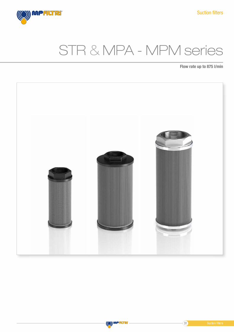
Flow rate up to 875 l/min
Suction fi lters
MPA - MPM seriesSTR &
Suction fi lters31
1
2
35
1
2
3 4
Flow rate up to 875 l/min
GENERAL INFORMATIONSTR MPA-MPM&
Weights [kg]
Filter series
see page 35
see page 37STR
MPA - MPM
With magnetic column
MPM
1
4
3
5
6
4
78
9
1
4
3
2
5
6
4
78
9
STR STR
Without bypass
With bypass
1 - Connection: Polyamide, GF reinforced
2 - Core tube: Tinned Steel
3 - Wire mesh
4 - End cap: Polyamide, GF reinforced
5 - Bypass valve: Polyamide, GF reinforced - Steel
STR materials
STR
MPA - MPM
1 - Connection: Aluminium
2 - Magnetic column
3 - Tie rod: Galvanized Steel
4 - End cap: Galvanized Steel
5 - Core tube: Galvanized Steel
6 - Filter media: Wire mesh
7 - Bottom: Galvanized Steel
8 - Washer: Galvanized Steel
9 - Self-locking nut: Galvanized Steel - Nylon
MPA - MPM materials
From -25 °C to +110 °C
Temperature
Opening pressure 30 kPa (0.3 bar)
Bypass valve
Fluid fl ow through the fi lter
element from OUT to IN.
Elements
Suction fi lters
STR is a range of suction strainers for protection of the downstream
pump against the coarse contamination.
They are placed below the oil level directly connected to the suction
line of the pump.
Available features:- Female threaded connections up to 3”, for a maximum flow rate
of 875 l/min
- Bypass valve, to relieve excessive pressure drop across the fi lter media
Common application:- Mobile machines (Construction and Agriculture machines)
- Industrial equipment
MPA and MPM are ranges of suction strainers for protection of the
downstream pump against the coarse contamination.
They are placed below the minimum oil level, directly connected to the
suction line of the pump.
The robust design allows the use of these fi lters in any heavy duty
application.
Available features:- Female threaded connections up to 3”, for a maximum flow rate
of 875 l/min
- Magnetic column (MPM), to hold the ferrous particles
Common application:Industrial equipment
Description Technical data
Without magnetic column
MPA
Suction fi lters 32
GENERAL INFORMATION STR MPA-MPM&Pressure drop
9
6
3
0
0 15 30 45 60 75
3/ 8” 1/ 2”
3/ 4”
Flow rate l/min
∆p
kP
a
9
6
3
0
0 50 100 150 200 250
1” 1 1/ 4”
1 1/ 2”
Flow rate l/min
∆p
kP
a
9
6
3
0
0 175 350 525 700 875
2” 2 1/ 2”
3”
Flow rate l/min
∆p
kP
a
STR
MPA - MPM
Style S Style B
Hydraulic symbols
Filter series
OUT
IN
OUT
IN
••
•
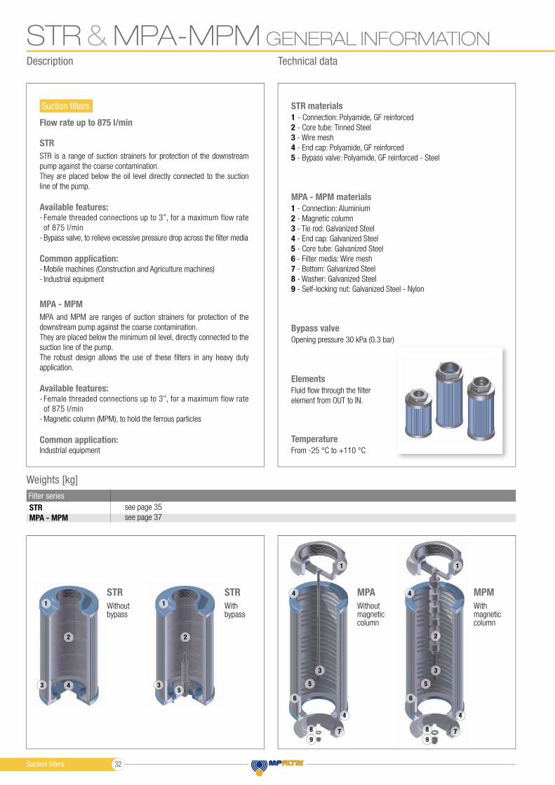
The curves are plotted using mineral oil with density of 0.86 kg/dm3 in compliance with ISO 3968.
∆p varies proportionally with density.
Filters pressure drop ∆p
in function of connection type
STR & MPA - MPM
Flow rates [l/min]
Filter series
Maximum flow rate for a complete suction filter with a pressure drop ∆p = 0.08 bar.
The reference fluid has a kinematic viscosity of 30 mm2/s (cSt)
and a density of 0.86 kg/dm3.
For different pressure drop or fluid viscosity we recommend to use
our selection software available on www.mpfiltri.com.
Please, contact our Sales Department for further additional information.
l/min
19
28
67
126
167
258
480
854
480
995
Thread
3/8”
1/2”
3/4”
1”
1 1/4”
1 1/2”
2”
2 1/2”
2”
3”
Suction filters33
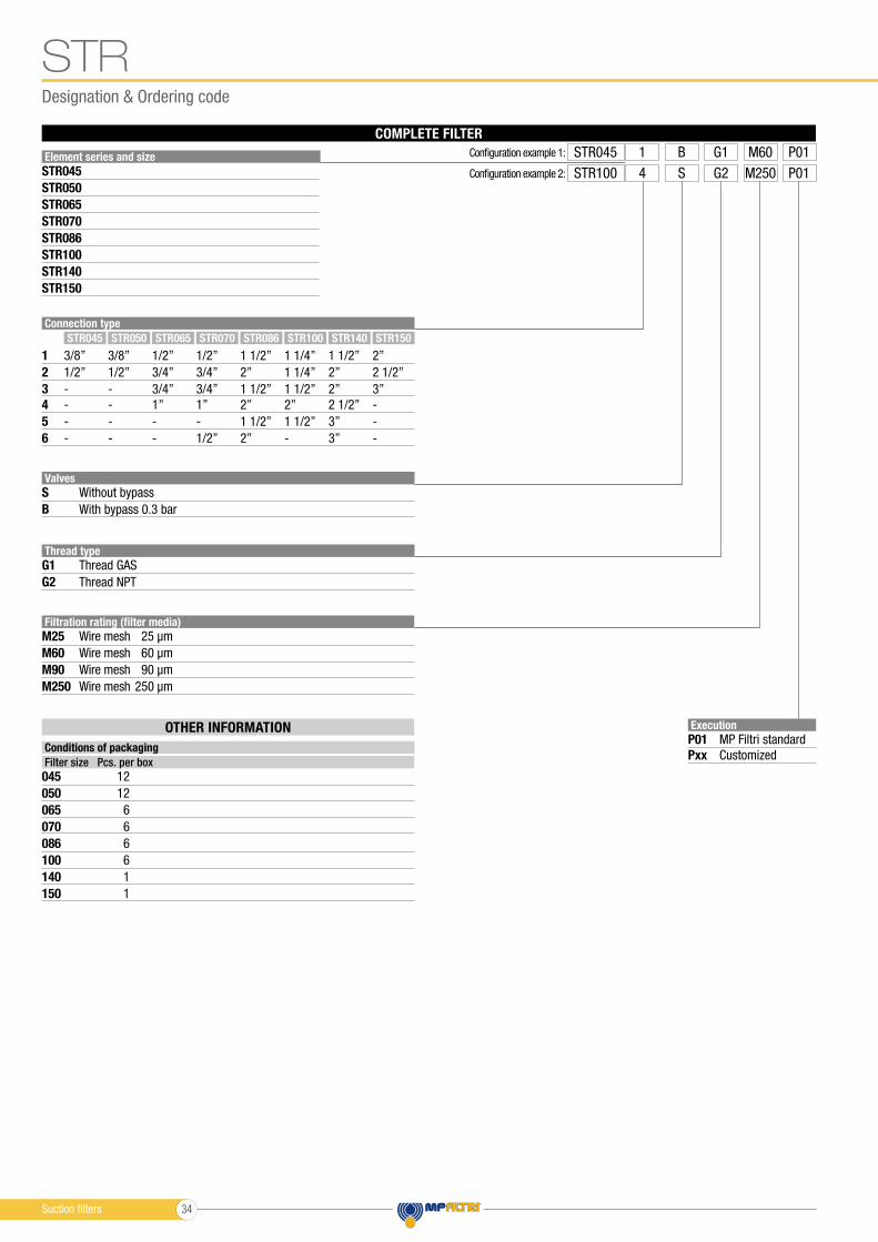
Designation & Ordering code
STR
OTHER INFORMATION
Conditions of packaging
Filter size Pcs. per box
045
086
065
140
050
100
070
150
12
6
6
1
12
6
6
1
Element series and size
STR045
STR086
STR065
STR140
STR050
STR100
STR070
STR150
Execution
P01
Pxx
MP Filtri standard
Customized
Connection type
1
3
2
4
5
6
Valves
Thread type
S
G1
B
G2
STR045 STR086STR065 STR140STR050 STR100STR070 STR150
Without bypass
Thread GAS
3/8”
1/2”
-
-
-
-
1/2”
3/4”
3/4”
1”
-
1/2”
1 1/2”
2”
2”
2 1/2”
3”
3”
3/8”
1/2”
-
-
-
-
1 1/2”
2”
1 1/2”
2”
1 1/2”
2”
2”
2 1/2”
3”
-
-
-
1/2”
3/4”
3/4”
1”
-
-
1 1/4”
1 1/4”
1 1/2”
2”
1 1/2”
-
With bypass 0.3 bar
Thread NPT
COMPLETE FILTER
Filtration rating (filter media)
M25
M90
M60
M250
Wire mesh 25 µm
Wire mesh 90 µm
250 µm
Wire mesh 60 µm
Wire mesh
Configuration example 1: STR045 M60B1 G1 P01
Configuration example 2: STR100 M250S4 G2 P01
Suction filters 34
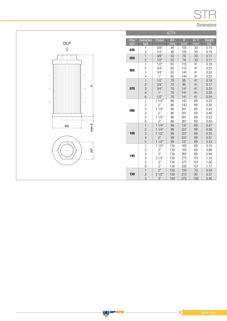
Dimensions
STR
max 8
STR
Filter size
A / F[mm]
H[mm]
ØD[mm]
Weight[kg]
ThreadConnectiontype
045
050
065
070
086
100
140
150
30
30
30
30
41
41
41
41
41
41
41
41
41
69
69
69
69
69
69
69
69
69
69
69
69
69
69
101
101
101
70
90
100
105
105
79
79
110
110
144
144
95
95
141
141
141
143
143
201
201
261
261
137
227
227
227
137
160
160
262
272
272
330
150
212
272
46
46
52
52
65
65
65
65
70
70
70
70
70
86
86
86
86
86
86
99
99
99
99
99
130
130
130
130
130
130
150
150
150
0.15
0.19
0.11
0.11
0.19
0.22
0.24
0.22
0.18
0.17
0.23
0.22
0.24
0.33
0.30
0.43
0.40
0.53
0.50
0.47
0.58
0.55
0.51
0.43
0.70
0.68
0.94
1.10
1.00
1.17
0.34
0.37
0.40
3/8”
1/2”
3/8”
1/2”
1/2”
3/4”
3/4”
1”
1/2”
3/4”
3/4”
1”
1/2”
1 1/2”
2”
1 1/2”
2”
1 1/2”
2”
1 1/4”
1 1/4”
1 1/2”
2”
1 1/2”
1 1/2”
2”
2”
2 1/2”
3”
3”
2”
2 1/2”
3”
1
2
1
2
1
2
3
4
1
2
3
4
6
1
2
3
4
5
6
1
2
3
4
5
1
2
3
4
5
6
1
2
3
OUT
Suction filters35
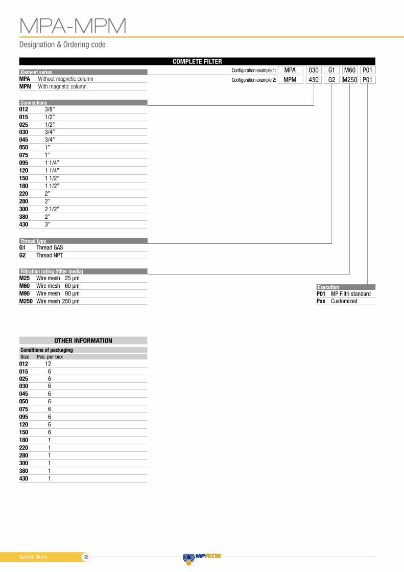
Designation & Ordering code
MPA-MPM
COMPLETE FILTER
OTHER INFORMATION
Conditions of packaging
Size Pcs. per box
12
6
6
6
6
1
1
1
6
6
6
6
6
1
1
1
Element series
MPA
MPM
Execution
P01
Pxx
MP Filtri standard
Customized
Connections
012
012
025
025
015
015
030
030
045
045
050
050
075
075
095
095
150
150
220
220
120
120
180
180
280
280
300
300
380
380
430
430
Thread type
G1
G2
Thread GAS
3/8”
1/2”
1/2”
3/4”
3/4”
1”
1”
1 1/4”
1 1/2”
2”
1 1/4”
1 1/2”
2”
2 1/2”
2”
3”
Thread NPT
Filtration rating (filter media)
M25
M90
M60
M250
Wire mesh 25 µm
Wire mesh 90 µm
250 µm
Wire mesh 60 µm
Wire mesh
Without magnetic column
With magnetic column
Configuration example 1: MPA M60030 G1 P01
Configuration example 2: MPM M250430 G2 P01
Suction filters 36
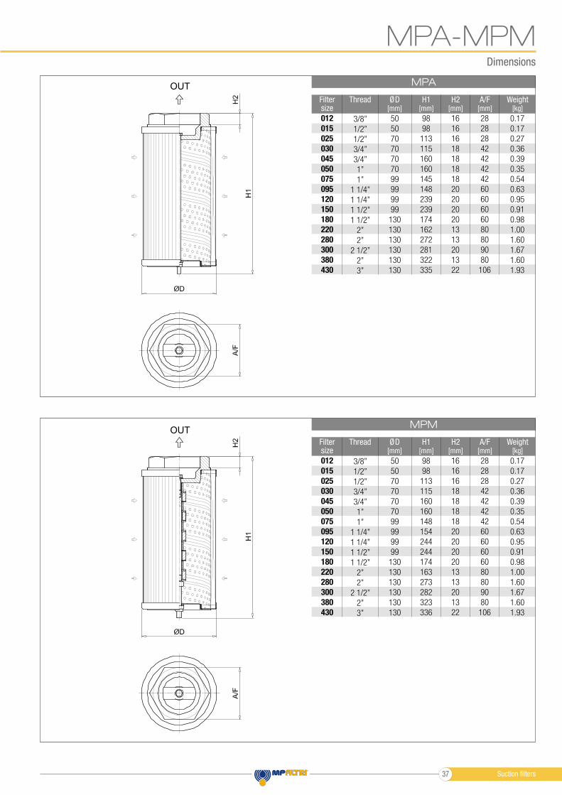
Dimensions
MPA
MPM
MPA-MPM
Filter size
Filter size
A/F[mm]
A/F[mm]
H2[mm]
H2[mm]
H1[mm]
H1[mm]
Weight[kg]
Weight[kg]
012
015
025
030
045
050
075
095
120
150
180
220
280
300
380
430
012
015
025
030
045
050
075
095
120
150
180
220
280
300
380
430
28
28
28
42
42
42
42
60
60
60
60
80
80
90
80
106
28
28
28
42
42
42
42
60
60
60
60
80
80
90
80
106
16
16
16
18
18
18
18
20
20
20
20
13
13
20
13
22
16
16
16
18
18
18
18
20
20
20
20
13
13
20
13
22
98
98
113
115
160
160
145
148
239
239
174
162
272
281
322
335
98
98
113
115
160
160
148
154
244
244
174
163
273
282
323
336
0.17
0.17
0.27
0.36
0.39
0.35
0.54
0.63
0.95
0.91
0.98
1.00
1.60
1.67
1.60
1.93
0.17
0.17
0.27
0.36
0.39
0.35
0.54
0.63
0.95
0.91
0.98
1.00
1.60
1.67
1.60
1.93
50
50
70
70
70
70
99
99
99
99
130
130
130
130
130
130
50
50
70
70
70
70
99
99
99
99
130
130
130
130
130
130
ØD[mm]
ØD[mm]
Thread
Thread
3/8”
1/2”
1/2”
3/4”
3/4”
1”
1”
1 1/4”
1 1/4”
1 1/2”
1 1/2”
2”
2”
2 1/2”
2”
3”
3/8”
1/2”
1/2”
3/4”
3/4”
1”
1”
1 1/4”
1 1/4”
1 1/2”
1 1/2”
2”
2”
2 1/2”
2”
3”
OUT
OUT
Suction filters37
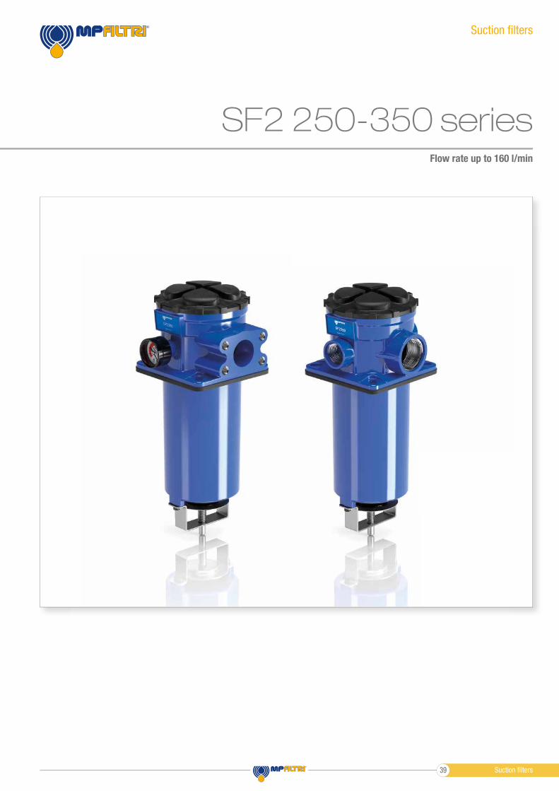
SF2 250-350 seriesFlow rate up to 160 l/min
Suction fi lters
Suction fi lters39
Flow rate up to 160 l/min
GENERAL INFORMATIONSF2 250-350
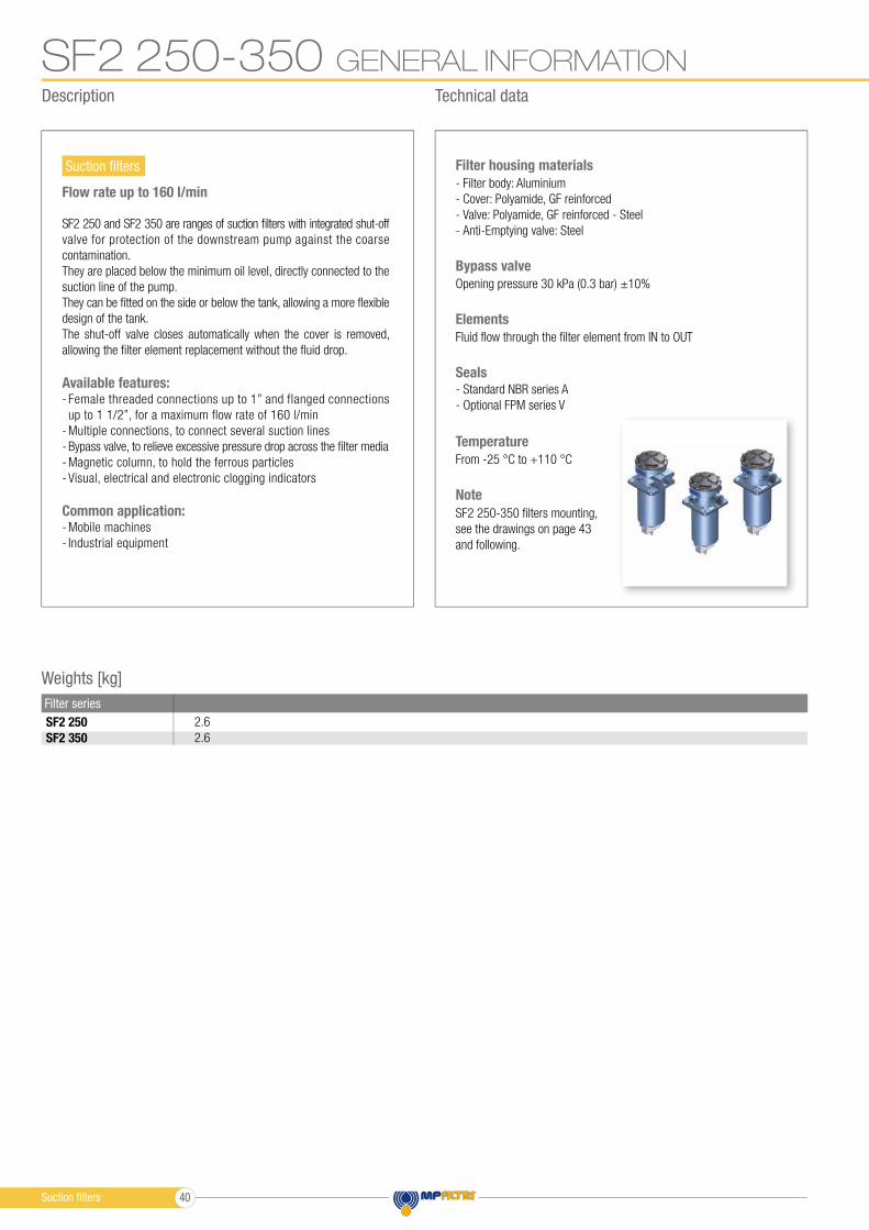
Weights [kg]
Filter series
2.6
2.6
SF2 250
SF2 350
Suction fi lters- Filter body: Aluminium
- Cover: Polyamide, GF reinforced
- Valve: Polyamide, GF reinforced - Steel
- Anti-Emptying valve: Steel
Filter housing materials
From -25 °C to +110 °C
Temperature
Opening pressure 30 kPa (0.3 bar) ±10%
Bypass valve
Fluid fl ow through the fi lter element from IN to OUT
Elements
- Standard NBR series A
- Optional FPM series V
Seals
Note
SF2 250-350 fi lters mounting,
see the drawings on page 43
and following.
SF2 250 and SF2 350 are ranges of suction fi lters with integrated shut-off
valve for protection of the downstream pump against the coarse
contamination.
They are placed below the minimum oil level, directly connected to the
suction line of the pump.
They can be fi tted on the side or below the tank, allowing a more fl exible
design of the tank.
The shut-off valve closes automatically when the cover is removed,
allowing the fi lter element replacement without the fl uid drop.
Available features:- Female threaded connections up to 1” and flanged connections
up to 1 1/2”, for a maximum flow rate of 160 l/min
- Multiple connections, to connect several suction lines
- Bypass valve, to relieve excessive pressure drop across the fi lter media
- Magnetic column, to hold the ferrous particles
- Visual, electrical and electronic clogging indicators
Common application:- Mobile machines
- Industrial equipment
Description Technical data
Suction fi lters 40
Filter element design - N Series
Filter series M25 M60 M90 M250 P10 P25
147 151 155 160 85 132 147 151 155 160 85 132
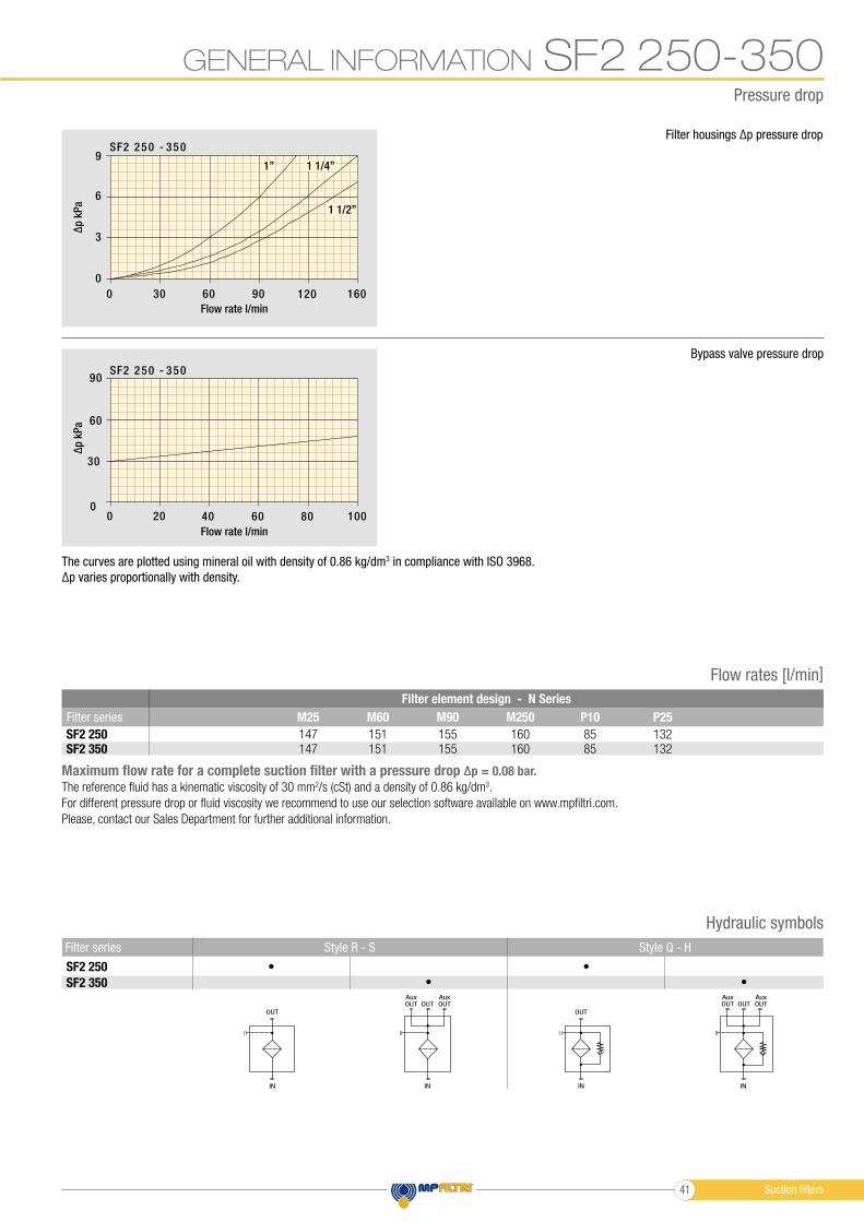
GENERAL INFORMATION SF2 250-350
The curves are plotted using mineral oil with density of 0.86 kg/dm3 in compliance with ISO 3968.
∆p varies proportionally with density.
Filter housings ∆p pressure drop
Bypass valve pressure drop
90
60
30
00 20 40 60 80 100
SF2 2 50 - 350
9
6
3
0
0 30 60 90 120 160
SF2 250 - 350
1 1/4”
1 1/2”
1”
Pressure drop
Flow rate l/min
Flow rate l/min
∆p
kP
a∆
p k
Pa
OUT
IN
SF2 250
SF2 350
Style Q - HStyle R - S Filter series
• •
• •
OUTAux
OUT OUTAux
IN
OUT
IN
OUTAux
OUT OUTAux
IN
Hydraulic symbols
Flow rates [l/min]
Maximum flow rate for a complete suction filter with a pressure drop ∆p = 0.08 bar.
The reference fluid has a kinematic viscosity of 30 mm2/s (cSt) and a density of 0.86 kg/dm3.
For different pressure drop or fluid viscosity we recommend to use our selection software available on www.mpfiltri.com.
Please, contact our Sales Department for further additional information.
SF2 250SF2 350
Suction filters41
Designation & Ordering code
SF2 250-350
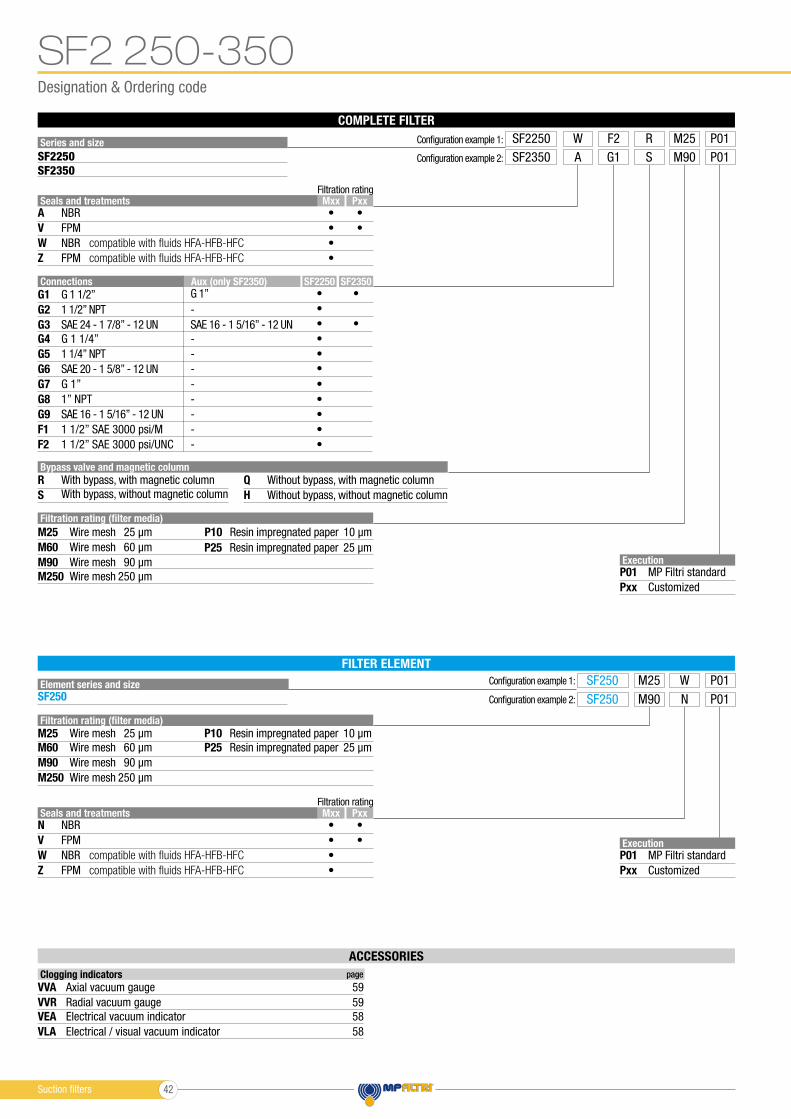
ACCESSORIES
Clogging indicators page
VVA
VEA
VVR
VLA
Axial vacuum gauge 59
Electrical vacuum indicator 58
Radial vacuum gauge 59
Electrical / visual vacuum indicator 58
FILTER ELEMENT
Element series and size
SF250
Configuration example 1:
Configuration example 2:
Execution
P01
Pxx
MP Filtri standard
Customized
SF250
SF250
M25
M90
W
N
P01
P01
Filtration rating (filter media)
Filtration rating (filter media)
Bypass valve and magnetic column
M25
M25
R Q
M90
M90
M60
M60
S H
M250
M250
Wire mesh
Wire mesh
With bypass, with magnetic column Without bypass, with magnetic column
25 µm
25 µm
Wire mesh
Wire mesh
90 µm
90 µm
Wire mesh
Wire mesh
With bypass, without magnetic column Without bypass, without magnetic column
60 µm
60 µm
Wire mesh
Wire mesh
250 µm
250 µm
Seals and treatments
Seals and treatments
N
A
W
W
Z
Z
V
V
Mxx
Mxx
Pxx
Pxx
•
•
•
•
•
•
•
•
•
•
•
•
NBR
NBR
NBR
NBR
FPM
FPM
FPM
FPM
Filtration rating
Filtration rating
compatible with fluids HFA-HFB-HFC
compatible with fluids HFA-HFB-HFC
compatible with fluids HFA-HFB-HFC
compatible with fluids HFA-HFB-HFC
COMPLETE FILTER
Series and size
Execution
P01
Pxx
MP Filtri standard
Customized
Configuration example 1: SF2250 F2W M25R P01
SF2250
SF2350
Configuration example 2: SF2350 G1A M90S P01
G2
G1
G3
G4
G6
G9
G5
G7
F1
G8
F2
1 1/2” NPT -
G 1 1/2” G 1”
SAE 24 - 1 7/8” - 12 UN SAE 16 - 1 5/16” - 12 UN
G 1 1/4” -
SAE 20 - 1 5/8” - 12 UN -
SAE 16 - 1 5/16” - 12 UN -
1 1/4” NPT -
G 1” -
1 1/2” SAE 3000 psi/M -
1” NPT -
1 1/2” SAE 3000 psi/UNC -
Connections Aux (only SF2350) SF2250 SF2350
•
•
•
•
•
•
•
•
•
•
•
•
•
P10
P10
P25
P25
Resin impregnated paper
Resin impregnated paper
10 µm
10 µm
Resin impregnated paper
Resin impregnated paper
25 µm
25 µm
Suction filters 42
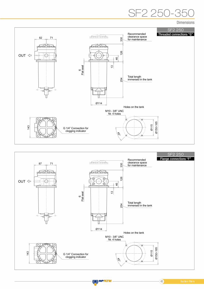
Dimensions
SF2 250
SF2 250
SF2 250-350
Threaded connections “G”
Flange connections “F”
6F
lat seal
6F
lat seal
Total lengthimmersed in the tank
Total lengthimmersed in the tank
Holes on the tank
Holes on the tank
M10 - 3/8” UNCNr. 4 holes
M10 - 3/8” UNCNr. 4 holes
G 1/4” Connection forclogging indicator
G 1/4” Connection forclogging indicator
Recommendedclearance spacefor maintenance
Recommendedclearance spacefor maintenance
OUT
OUT
Suction filters43
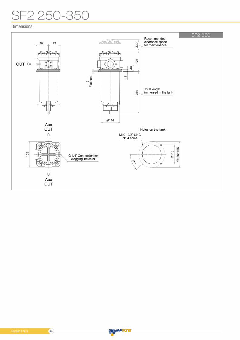
Dimensions
SF2 350
SF2 250-350
Holes on the tank
OUT
OUT
OUT
Aux
Aux
Total lengthimmersed in the tank
M10 - 3/8” UNCNr. 4 holes
Recommendedclearance spacefor maintenance
6F
lat seal
G 1/4” Connection forclogging indicator
Suction filters 44
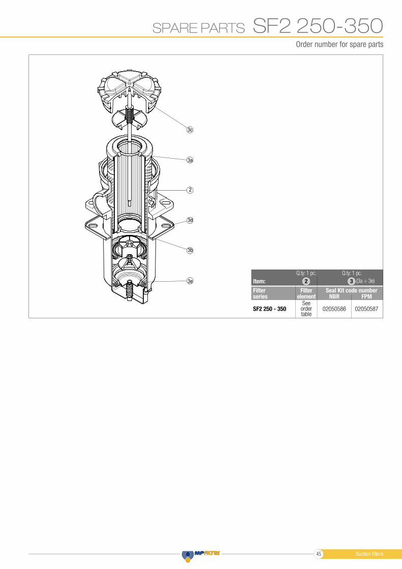
SF2 250-350Order number for spare parts
SPARE PARTS
3c
3a
3d
3b
3e
2
Item:
Filter series
Seal Kit code numberFilterelement NBR FPM
SF2 250 - 350 02050586 02050587See
order table
2
Q.ty: 1 pc.Q.ty: 1 pc.
(3a ÷ 3e)3
Suction fi lters45
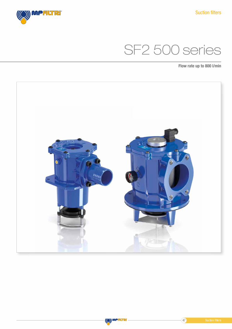
SF2 500 seriesFlow rate up to 800 l/min
Suction fi lters
Suction fi lters47
SF2 500-501
SF2 503
SF2 504
SF2 505
SF2 510
SF2 535
SF2 540
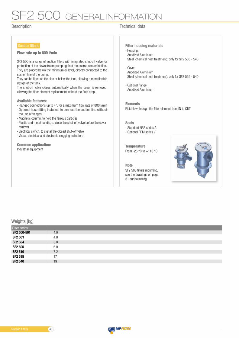
Flow rate up to 800 l/min- Housing:
Anodized Aluminium
Steel (chemical heat treatment): only for SF2 535 - 540
- Cover:
Anodized Aluminium
Steel (chemical heat treatment): only for SF2 535 - 540
- Optional fl ange:
Anodized Aluminium
Filter housing materials
From -25 °C to +110 °C
Temperature
Fluid fl ow through the fi lter element from IN to OUT
Elements
- Standard NBR series A
- Optional FPM series V
Seals
GENERAL INFORMATIONSF2 500
Weights [kg]
Filter series
4.0
4.8
5.8
6.0
7.2
17
19
Note
SF2 500 fi lters mounting,
see the drawings on page
51 and following
Description Technical data
Suction fi lters
SF2 500 is a range of suction fi lters with integrated shut-off valve for
protection of the downstream pump against the coarse contamination.
They are placed below the minimum oil level, directly connected to the
suction line of the pump.
They can be fi tted on the side or below the tank, allowing a more fl exible
design of the tank.
The shut-off valve closes automatically when the cover is removed,
allowing the fi lter element replacement without the fl uid drop.
Available features:- Flanged connections up to 4”, for a maximum fl ow rate of 800 l/min
- Optional hose fitting installed, to connect the suction line without
the use of fl anges
- Magnetic column, to hold the ferrous particles
- Plastic and metal handle, to close the shut-off valve before the cover
removal
- Electrical switch, to signal the closed shut-off valve
- Visual, electrical and electronic clogging indicators
Common application:Industrial equipment
Suction fi lters 48
SF2 500
SF2 501
SF2 503
SF2 504
SF2 505
SF2 510
SF2 535
SF2 540
GENERAL INFORMATION SF2 500
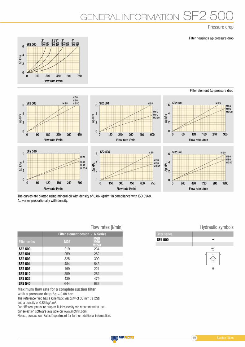
Filter housings ∆p pressure drop
Filter element ∆p pressure drop
6
4
2
00 150 300 450 600 750
SF2 500
4”SF2 504SF2 540
3”SF2 503SF2 535
2 1/2”SF2 501SF2 510
2”SF2 500SF2 505
ΔΔ
6
4
2
00 90 180 270 360 450
SF2 503
M 60
M 90
M 250M 256
4
2
00 60 120 180 240 300
SF2 505M 60
M 90
M 2 50
M 25
ΔΔ
6
4
2
00 150 300 450 600 750
SF2 535
M 60
M 90
M 25 0
M 25
Δ
6
4
2
00 120 240 360 480 600
SF2 504
M 60
M 90
M 250
M 25
6
4
2
00 60 120 180 240 300
SF2 510
M 60
M 90
M 250
M 25
Δ
The curves are plotted using mineral oil with density of 0.86 kg/dm3 in compliance with ISO 3968.
∆p varies proportionally with density.
Pressure drop
Flow rate l/min
Flow rate l/min Flow rate l/min Flow rate l/min
Flow rate l/min Flow rate l/min
∆p
kP
a∆
p k
Pa
∆p
kP
a
∆p
kP
a
∆p
kP
a
∆p
kP
a
Δ
6
4
2
00 240 480 720 960 1200
SF2 540
M 60
M 90
M 250
M 2 5
Flow rate l/min
∆p
kP
a
Hydraulic symbols
Filter series
SF2 500 •
OUT
IN
Filter element design - N Series
Flow rates [l/min]
Filter series
219 234
259 282
325 390
484 543
199 221
259 282
439 479
644 688
M60M90
M250M25
Maximum flow rate for a complete suction filter with a pressure drop ∆p = 0.08 bar.
The reference fluid has a kinematic viscosity of 30 mm2/s (cSt)
and a density of 0.86 kg/dm3.
For different pressure drop or fluid viscosity we recommend to use
our selection software available on www.mpfiltri.com.
Please, contact our Sales Department for further additional information.
Suction filters49
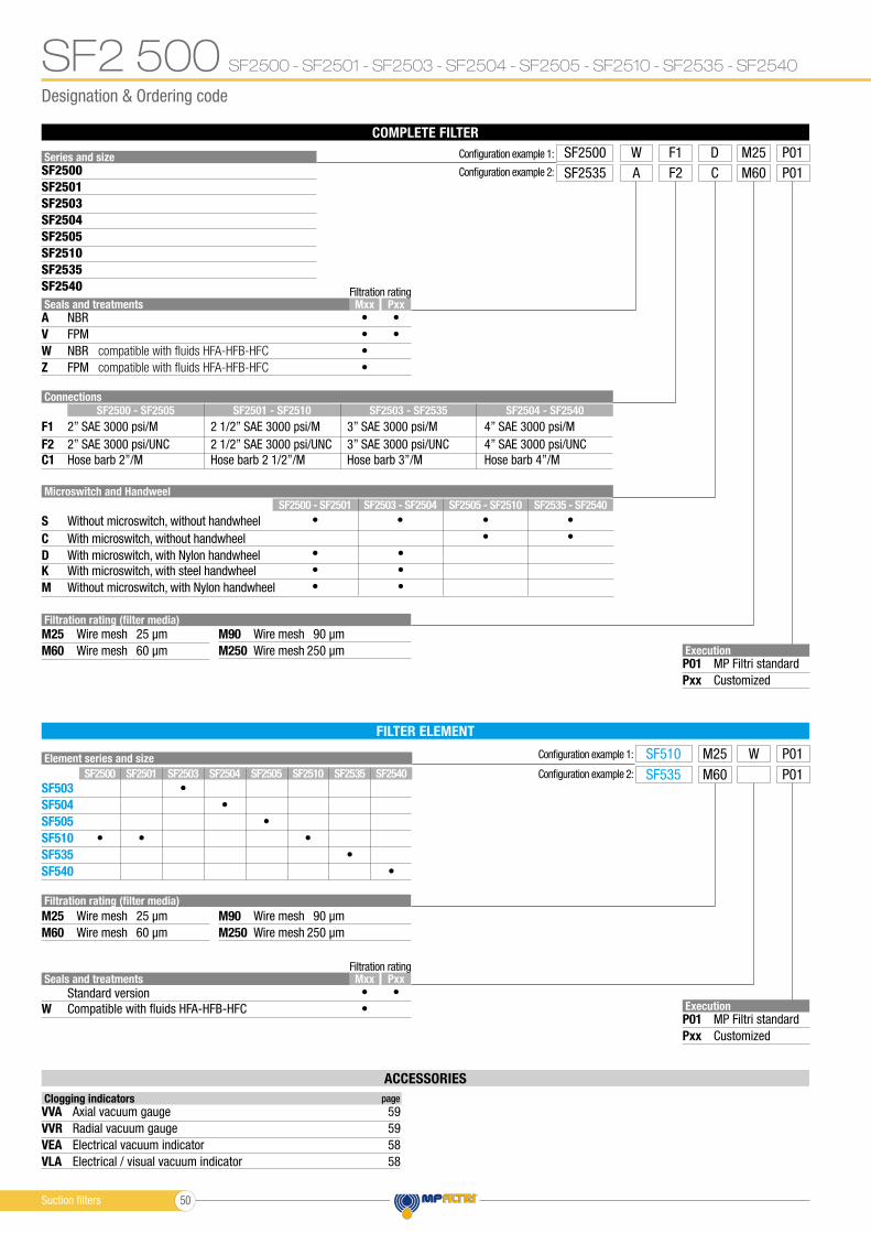
Designation & Ordering code
SF2500 - SF2501 - SF2503 - SF2504 - SF2505 - SF2510 - SF2535 - SF2540
ACCESSORIES
FILTER ELEMENT
Element series and size
SF503
SF504
SF505
SF510
SF535
SF540
Execution
P01
Pxx
MP Filtri standard
Customized
Filtration rating (filter media)
Filtration rating (filter media)
Microswitch and Handweel
M25
M25
S
D
M90
M90
M60
M60
C
K
M
M250
M250
Wire mesh
Wire mesh
Without microswitch, without handwheel
With microswitch, with Nylon handwheel
25 µm
25 µm
Wire mesh
Wire mesh
90 µm
90 µm
Wire mesh
Wire mesh
With microswitch, without handwheel
With microswitch, with steel handwheel
Without microswitch, with Nylon handwheel
60 µm
60 µm
Wire mesh
Wire mesh
250 µm
250 µm
Seals and treatments
Seals and treatments
A
W
Z
W
V
Mxx
Mxx
Pxx
Pxx
•
•
•
•
•
•
•
•
•
•
• •
• •
•
•
•
•
• •
• •
•
•
•
•
•
•
•
Standard version
NBR
NBR
FPM
Compatible with fluids HFA-HFB-HFC
FPM
Filtration rating
Filtration rating
compatible with fluids HFA-HFB-HFC
compatible with fluids HFA-HFB-HFC
COMPLETE FILTER
Series and size Configuration example 1:
Execution
P01
Pxx
MP Filtri standard
Customized
SF2500 F1W M25D P01SF2500
SF2503
SF2510
SF2505
SF2501
SF2504
SF2535
SF2540
Configuration example 2: SF2535 F2A M60C P01
F2
F1
C1
2” SAE 3000 psi/UNC
2” SAE 3000 psi/M
Hose barb 2”/M
Configuration example 1:
Configuration example 2:
SF510
SF535
M25
M60
W P01
P01
Connections
SF2500 - SF2505
SF2500 - SF2501
SF2500 SF2505
SF2503 - SF2535
SF2505 - SF2510
SF2503 SF2535
SF2501 - SF2510
SF2503 - SF2504
SF2501 SF2510
SF2504 - SF2540
SF2535 - SF2540
SF2504 SF2540
2 1/2” SAE 3000 psi/M 3” SAE 3000 psi/M 4” SAE 3000 psi/M
Hose barb 2 1/2”/M Hose barb 3”/M Hose barb 4”/M
2 1/2” SAE 3000 psi/UNC 3” SAE 3000 psi/UNC 4” SAE 3000 psi/UNC
Clogging indicators page
VVA
VEA
VVR
VLA
Axial vacuum gauge 59
Electrical vacuum indicator 58
Radial vacuum gauge 59
Electrical / visual vacuum indicator 58
SF2 500
Suction filters 50
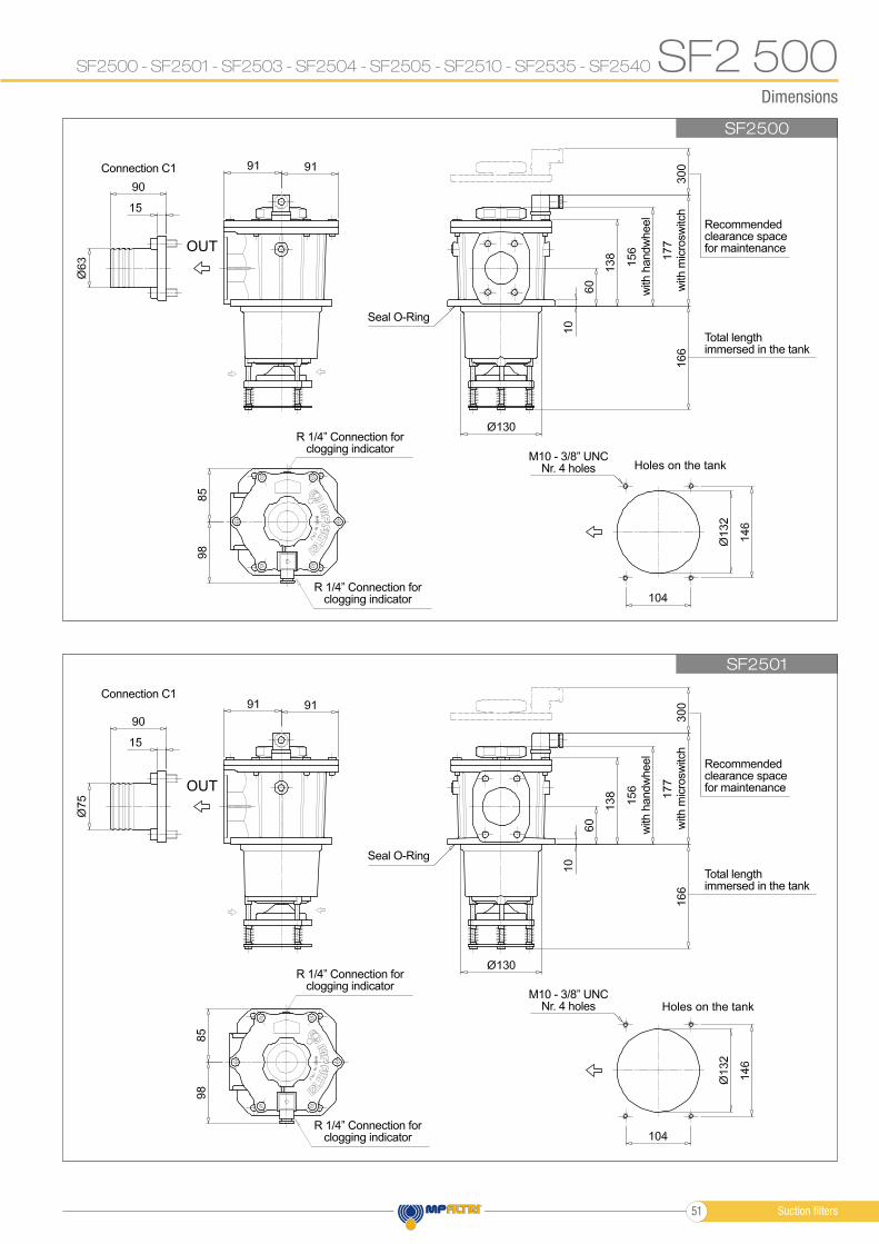
Dimensions
SF2500
SF2501
SF2500 - SF2501 - SF2503 - SF2504 - SF2505 - SF2510 - SF2535 - SF2540 SF2 500
Holes on the tank
Holes on the tank
OUT
OUT
Total lengthimmersed in the tank
Total lengthimmersed in the tank
M10 - 3/8” UNCNr. 4 holes
M10 - 3/8” UNCNr. 4 holes
Recommendedclearance spacefor maintenance
Recommendedclearance spacefor maintenance
with
handw
heel
with
handw
heel
Seal O-Ring
Seal O-Ring
Connection C1
Connection C1
with
mic
rosw
itch
with
mic
rosw
itch
R 1/4” Connection forclogging indicator
R 1/4” Connection forclogging indicator
R 1/4” Connection forclogging indicator
R 1/4” Connection forclogging indicator
Suction filters51
Dimensions
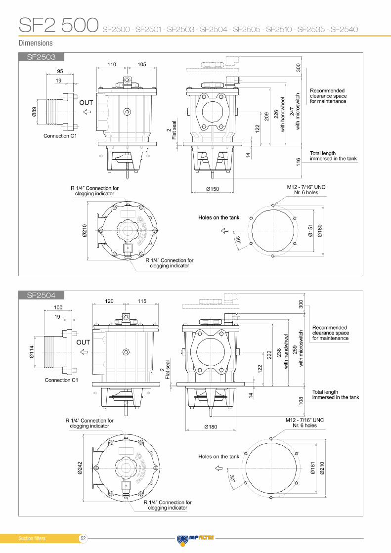
SF2503
SF2504
SF2500 - SF2501 - SF2503 - SF2504 - SF2505 - SF2510 - SF2535 - SF2540SF2 500
Holes on the tank
Holes on the tankHoles on the tank
OUT
OUT
Total lengthimmersed in the tank
Total lengthimmersed in the tank
M12 - 7/16” UNCNr. 6 holes
M12 - 7/16” UNCNr. 6 holes
Recommendedclearance spacefor maintenance
Recommendedclearance spacefor maintenance
with
handw
heel
with
handw
heel
2F
lat seal
2F
lat seal
Connection C1
Connection C1
with
mic
rosw
itch
with
mic
rosw
itch
R 1/4” Connection forclogging indicator
R 1/4” Connection forclogging indicator
R 1/4” Connection forclogging indicator
R 1/4” Connection forclogging indicator
Suction filters 52
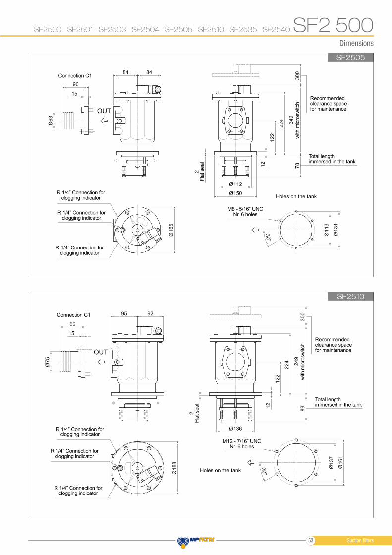
Dimensions
SF2505
SF2510
SF2500 - SF2501 - SF2503 - SF2504 - SF2505 - SF2510 - SF2535 - SF2540 SF2 500
Holes on the tank
Holes on the tank
OUT
OUT
Total lengthimmersed in the tank
Total lengthimmersed in the tank
M12 - 7/16” UNCNr. 6 holes
M8 - 5/16” UNCNr. 6 holes
Recommendedclearance spacefor maintenance
Recommendedclearance spacefor maintenance
2F
lat seal
2F
lat seal
Connection C1
Connection C1
with
mic
rosw
itch
with
mic
rosw
itch
R 1/4” Connection forclogging indicator
R 1/4” Connection forclogging indicator
R 1/4” Connection forclogging indicator
R 1/4” Connection forclogging indicator
R 1/4” Connection forclogging indicator
R 1/4” Connection forclogging indicator
Suction filters53
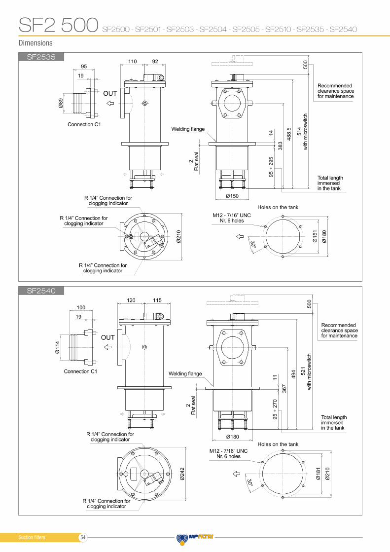
Dimensions
SF2535
SF2540
SF2500 - SF2501 - SF2503 - SF2504 - SF2505 - SF2510 - SF2535 - SF2540SF2 500
Holes on the tank
Holes on the tank
OUT
OUT
Total lengthimmersedin the tank
Total lengthimmersedin the tank
M12 - 7/16” UNCNr. 6 holes
M12 - 7/16” UNCNr. 6 holes
Recommendedclearance spacefor maintenance
Recommendedclearance spacefor maintenance
2F
lat seal
2F
lat seal
Connection C1
Connection C1
Welding flange
Welding flange
with
mic
rosw
itch
with
mic
rosw
itch
R 1/4” Connection forclogging indicator
R 1/4” Connection forclogging indicator
R 1/4” Connection forclogging indicator
R 1/4” Connection forclogging indicator
R 1/4” Connection forclogging indicator
Suction filters 54
3c
3f
2
3a
3d
3e
3g
3b
3c
3f
2
3a
3b
3e
3g
3c
3f
2
3a
3b
3e
3g
3d
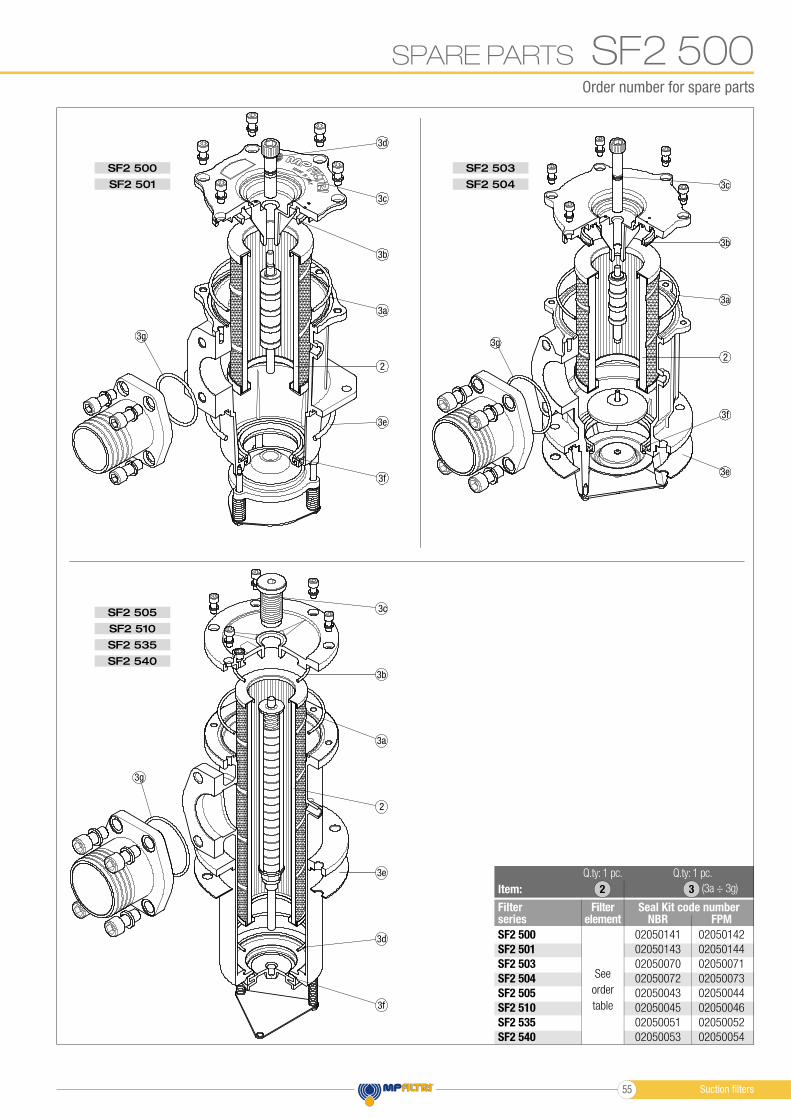
SF2 500
SF2 505
SF2 535
SF2 503
SF2 501
SF2 510
SF2 540
SF2 504
Order number for spare parts
SPARE PARTS
Item:
Filter series
Seal Kit code numberFilterelement NBR FPM
SF2 500
SF2 501
SF2 503
SF2 504
SF2 505
SF2 510
SF2 535
SF2 540
02050141
02050143
02050070
02050072
02050043
02050045
02050051
02050053
02050142
02050144
02050071
02050073
02050044
02050046
02050052
02050054
See
order
table
2
Q.ty: 1 pc.Q.ty: 1 pc.
(3a ÷ 3g)3
SF2 500
Suction fi lters55

![Ventilterminal MPA−L...Pneumatik MPA−L Ventilterminal Typ: MPA−L−MPM−VI MPA−L−FB−VI Beskrivning 556 358 sv 1008NH [722 283] Ventilterminal MPA−L. ... betyder att](https://img.pdfslide.net/doc/110x75/60912199dc0d2a008521a11b/ventilterminal-mpaal-pneumatik-mpaal-ventilterminal-typ-mpaalampmavi.jpg)

![Ventilinsel MPA-S - festo.com · PDF fileBeschreibung Pneumatik Ventilinselmit MPA-S Pneumatik Typ: MPA-FB MPA-CPI MPA-MPM-und MPA-ASI- 534240 1309f [8028623] Ventilinsel MPA-S](https://img.pdfslide.net/doc/110x75/5a79d19f7f8b9ab83f8b7435/ventilinsel-mpa-s-festocom-pneumatik-ventilinselmit-mpa-s-pneumatik-typ-mpa-fb.jpg)


![Valve terminal MPA-S - Festo USA · Pneumatic components description Valveterminalwith MPA-Spneumatics Type: MPA-FB MPA-CPI MPA-MPM-…and MPA-ASI-… 534241 1309f [8028624] Valve](https://img.pdfslide.net/doc/110x75/5c5bd85409d3f236368c6efe/valve-terminal-mpa-s-festo-usa-pneumatic-components-description-valveterminalwith.jpg)