Embed Size (px)
Citation preview

SU G IYAMA CH AIN CO ., LTD .
1
Since being founded in 1946 as a bicycle chain manufacturer, Sugiyama Chain has
concentrated its efforts on the manufacturing of high quality roller chain. With decades
of experience and continuous research in the roller chain field, we offer a complete line
of roller chain. Our chain is recognized throughout the world for its quality and
innovation. Sugiyama Chain obtained ISO 9001certification in December 2000 further
enhancing its quality assurance. Our mission is to provide the highest quality roller chain
with strength, durability, and reliability to our customer's satisfaction. We will continue
to perfect our chain under our strict quality control system. Most of the items in this
catalog are available from SY's distributors all over the world, or are in stock at Service
Centers.
Certificate Number : JQA-QM5873
Organization :
SUGIYAMA CHAIN CO.,LTD.
Scope of Registration :
DESIGN, DEVELOPMENT AND MANUFACTURE OF PRESION POWER
TRANSMISSION ROLLER CHAIN, LEAF CHAIN AND CONVEYOR CHAIN.

DIES AND OTHERSImproved, sophisticated dies are studied and developed in our factory shop.
MODERNIZED HEAT TREATMENT EQUIPMENTOur heat treatment equipments have been updated for severe control on heated parts. Also, extreme attention is given to the quality control of the heat treated parts.
ADVANCED FULLY AUTOMATICASSEMBLY MACHINEOur newly designed advanced autmatic assembly machines provide great-er uniformity and closer tolerance of the products.
QC DEPARTMENTYour ordered chains are carefully and closely inspected at each produc-tion process by our QC-oriented specialists.
AUTOMATIC STRAGE AND HANDLING SYSTEMHandling of many different parts and semi-finished products are effectively controlled for production.
COLD FORGING MACHINESMain frame for SBR Solid Bushing and SBR Solid Roller are made with these machines.
FATIGUE TEST MACHINEVery important for the quality evaluation for further improvement of the chain life.
2
SY's advanced research and development

SY's new products guide
3
Maintenanc e F ree R oller C hainsee page 56
S elf - L ube C hainsee page 48
A qua - P roof R oller C hainsee page 40
S S S s eries S tainles s S teel C hainsee page 36
Double C apac ity C hainsee page 32
S ilver - S B Rsee page 4
New C onnec ting L inksee page 4
patent pending
S olid B us hing and R ollersee page 4~5
patent pending
patent pending
patent pending

SY 80
S ilver
S BR
conventional
chains
0.1
100 200 300 Hours
0.2
0.3
0.4
(%)
E longation
Wear res is tanc e tes t
R
B S S T A NDA R D R OL L E R C HA INSA NS I S T A NDA R D R OL L E R C HA INSS T R A IG HT S IDE B A R C HA INSHE A V Y -S E R IE S R OL L E R C HA INSOIL -F IE L D C HA INSS UP E R R OL L E R C HA INSDOUB L E C A P A C IT Y C HA INSS -S E R IE S R OL L E R C HA INSDOUB L E P IT C H R OL L E R C HA INSHOL L OW-P IN C HA INS
THE ULTIMATE ROLLER CHAIN LONG LIFE SERIES
S B RS ilver S B R
R OL L E R C HA IN
®
4
NE W R OLLE R C HAIN has up to 25%Higher Working LoadsWith big 5 point for R oller C hain
① S olid B ushing and R oller② High Allowable Load③ New C onnecting Link④ Long Life⑤ E xcellent appearance
High Allowable LoadClose to Super Chain BySpecial Pin(25% higher for #60 to #160)
Excellent appearance bySilver ColorPlate & Roller
New Connecting LinkConnecting Link have the same strength as chain.
Solid Bushing & RollerLong Lifeby Bushing More than 2 time (by our test)
SY Solid Bushing assures perfect straight ID.surface after assembly.

5
R
Bushing ID becomes barrel-shape a result of press fit and makes uneven contact be-tween pin and bushing.
SY solid bushing assures perfect straight ID surface after assembly.
S ilver S B R C hainC onventional C hain
Curled Bushing Curler Roller Solid Bushing Solid Roller
Roundness inside bushing Excellent roundness inside bushing
Wear aress causing elongation bybarrel-shaped curled bushing.
Optimal bearing surface duc to perfecily cylindrical parts.
Before Assembly After Assembly Before Assembly After Assembly
SPECIMEN
MAGN FILTER40
3020
10
8 6
4 2
20
1510
5
40302010
8 6
4 2
20
1510
5
4030
2010
8 6
4 2
20
1510
5
40 30 20 10
8 6
4 2
20
1510
5
C HA
RT
No.
99
05
18
SPECIMEN
MAGN FILTER
4030
2010
8 6
4 2
20
1510
5
40302010
8 6
4 2
20
1510
5
4030
2010
8 6
4 2
20
1510
5
40 30 20 10
8 6
4 2
20
1510
5
C HA
RT
No.
99
11
16
X200 X200
SPECIMEN
MAGN FILTER
4030
2010
8 6
4 2
20
1510
5
40302010
8 6
4 2
20
1510
5
4030
2010
8 6
4 2
20
1510
5
40 30 20 10
8 6
4 2
20
1510
5
C HA
RT
No.
99
07
19
X200

SY Chain Products CONTENTS
SY Chain Products ContentsInformation (How to order)
BS Standard Roller ChainsEcological BS Style Roller ChainsANSI Standard Roller Chains
BS Straight Sidebar ChainsANSI Straight Sidebar Chains
HEAVY SERIES ROLLER CHAINS (H Series)
Standard Series (E Series)Heavy Series (HE Series)
Standard SeriesHeavy Series
Double Capacity ChainsS-Series Roller Chains
Drive SeriesConveyor Series(Standard Roller Type)(Carrier Roller Type)
Stainless Steel Chains (BS & ANSI)SS Double Pitch Roller ChainsSelection of Stainless Steel ChainAqua-Proof Roller Chains (BS & ANSI)Technical Information (Result of corrosion resistance test)NP BS Roller ChainsNP ANSI Roller ChainsNP Double Pitch Roller Chains
SB Standard ChainsSB Double Pitch Chains
Standard Hollow Pin ChainsDouble Pitch Hollow Pin ChainsStainless Hollow Pin ChainsDouble Pitch Stainless Hollow Pin Chains
…………
………………………………
……………………
…………
……………………
……………………
……………………
…………………………………………
…………………………………………
…………………………………
……………………
…………………………………………
8
10
15
16
22
23
24
26
28
30
30
32
33
34
35
35
35
36
37
38
40
41
42
43
44
45
45
46
46
47
47
STANDARD ROLLER CHAINSROLLER CHAINS
STRAIGHT SIDEBAR CHAINS
HEAVY SERIES ROLLER CHAINS
OIL-FIELD CHAINS
SUPER ROLLER CHAINS
SUPER LOAD CHAINS
DOUBLE PITCH ROLLER CHAINS
RUSTLESS CHAINS
SIDE BOW CHAINS
HOLLOW PIN CHAINS
6

SY Chain Products CO N TEN TS
SY Chain Products Contents
7
InformationSL AN SI Standard Roller ChainsSL D ouble Pitch Roller ChainsSLR BS Standard Roller Chains (TS Series)SLR AN SI Standard Roller Chains (TS Series)SLR AN SI Standard Roller Chains (CS Series)SLR D ouble Pitch Roller ChainsH ollow Pin Chains (SL Type)D ouble Pitch H ollow Pin Chains (SL Type)
InformationMaintenance Free Roller Chains
AL SeriesBL SeriesLL SeriesSelection of Leaf Chain
InformationBS Standard Attachment ChainsAN SI Standard Attachment ChainsD ouble Pitch Attachment ChainsSide Roller ChainsSpecial AA-1 Attachment ChainsTop Roller ChainsBook Binding Chain
81X Series3939 Attachment Chain
Trouble Shooting H intsSelection of Roller ChainRoller Chain quick Selection ChartSelection of Stainless Steel ChainSelection of Leaf ChainInstallation and ArrangementLubricationW ARN IN GCAU TIO NSTD H orsepower RatingSuper H orsepower Ratingindex
………………………………………………………………………………………………
……………………
…………………………………………
……………………………………………………………………………………
……………………
………………………………………………………………………………………………………………………………
48
49
50
51
52
53
54
55
55
56
57
58
59
60
61
62
64
66
68
70
70
71
71
72
73
74
76
77
38
61
78
79
80
81
82
86
87
L E A F C HA INS
A T T A C HME NT C HA INS
T E C HNIC A L INF OR MA T ION
E NG INE E R ING C HA INS
S E L F L UB E C HA INS (S interd S teel B us hing)
ME INT E NA NC E F R E E C HA INS
MA INT E NA NC E F R E E R OL L E R C HA INS
RO
LL
ER
CH
AIN
SD
OU
BL
E
PIT
CH
RO
LL
ER
C
HA
INS
RU
ST
LE
SS
CH
AIN
SS
IDE
B
OW
CH
AIN
SH
OL
LO
W
PIN
CH
AIN
SM
AIN
TE
NA
NC
EF
RE
E
CH
AIN
SL
EA
FC
HA
INS
AT
TA
CH
ME
NT
CH
AIN
SE
NG
INE
ER
ING
CH
AIN
ST
EC
HN
ICA
LIN
FO
RM
AT
ION

RO LLER CH AIN S
STAN D ARD RO LLER CH AIN S
8
C HA IN P A R T S
C HA IN C ONNE C T ION P A R T S
R oller Link(T ype R /L)
P in LinkR iveted
(T ype R )
P in Link C ottered (T ype C )
S pring C lip(T ype S p C L)
"S " P in(T ype S )
C ottered(T ype C )
T hrough"S " P in (T ype T S )
R oll P in
Offset(T ype O/L)
R UN B E T T E R WIT H S Y S P E C IF Y Y OUR R E QUIR E ME NT S
S T ANDAR D P AC K ING
HOW T O OR DE R Chain number, type:riveted or cottered, length and quantity are the necessary information for us to fill in your order. At the very least, the chain pitch, roller di-ameter and roller link inside width should be given if the chain number is unknown.
SY roller chains are packed for convenient handling and storing. Each 10feet length is packed in a carton.50feet length and more are wound on reel.
specifically as possible when ordering a cut length of chain.
NOME NC L A T UR E
Plain chain consists of "SY chain No" and "Type of pin link". At-tachment chain has one space between "Type of pin link" and
"Space of attachment".
S Y 120-2(R ) 2L A-2
S Y chain No
T ype of pin link.
s trand
S pace of att.(L=P itch)
T ype of att.
RO
LL
ER
CH
AIN
S

RO LLER CH AIN S
9
R oller chain with connecting link (C /L) Ordinarily even number of pitches includes a C/L on one end.
R oller chain endlessUsually chains are furnished unendless. If an endless chain as-sembly is required, specify whether it is to be riveted endless or cotter-connected.
R oller chain with offset link (O/L)When an odd number of pitches is required,a C/L and an O/L are usually used.
R oller chain with connecting links (C /L's )on both ends .For odd pitches(not endless),2C/L's are incorporated on request.
R IV E T E D
C OT T E R E D
S ING LE AND MULT IP LE
C HA IN C ONS T R UC T ION
Riveted chain is assembled by staking the pin heads on both sides of the chain
Cottered chain is assembled by staking the pin heads on one side of the chain and drilling a hole in the other end to ac-commodate a cotter pin. This type of chain is easily assem-bled and disassembled in the field.
On multiple-strand types, all center plates are slip fitted(clear-ance-fitted) unless otherwise specified.
RO
LL
ER
CH
AIN
S

RO LLER CH AIN S
10
RO
LL
ER
CH
AIN
S
H
P
L RW
L R
W
TP
RDL 1
L C
L 2
L C
L 2
L 1 D R
T 1T 2
T 2
T 12T
T 2
TP
T 3
H
P
L RW
L R
W
TP
RDL 1
L C
L 2
L C
L 2
L 1 D R
T 1T 2
T 2
T 12T
T 2
TP
T 3
BS Standard Roller ChainsSY BS standard roller chains are standardized in accordance with ISO 606 B and fully inter-changeable with chains manufactured according to BS 228 and D IN 8187.Supplied, in rivet type, to European countries as well as replacement on machinery employing BS standard chains.
S YC hain
No.(B S )
Pitc h
0 6 B
-2
-3
P W R
9.525 5.72 6.35 3.28 12.6
22.9
33.2
13.4
23.7
33.7
6.3 7.1 8.2 1.61.251.0 10.24 8.92
16.9
24.9
1.7
2.9
4,2
0.41
0.78
1.18
R oller
Width Dia.
D
Dia.
Dimensions - mm
Pin Plate
Length Height Thic knessTrans .Pitc h
MinimumUltimateS trength
MaximumAllowable
Load
AverageC hain
Weight
LR LC L1 L2 T1 T2 T3H TP kN kN kg/m
0 6 B
36 40 42
76 77
S tandard Pac king
320P
526P
06B
Item S ee P age
R ust Less
Drive C hain S elec tion
C urled bushing is used.
1 Unit (10')
1 Unit (5m)

RO LLER CH AIN S
11
RO
LL
ER
CH
AIN
S
※R efer to page 80. “S elec tion of offset link”
S YC hain
No.(B S )
Pitc h
1 0 B
-2
-3
P W R
15.875 9.65 10.16 5.08 19.0
35.6
52.4
20.7
37.3
54.4
9.5 11.2 14.7 1.65 16.59 22.2
44.5
66.7
4.90
8.33
12.2
0.89
1.79
2.66
R oller
Width Dia.
D
Dia.
Dimensions - mm
Pin Plate
Length Height Thic knessTrans .Pitc h
MinimumUltimateS trength
MaximumAllowable
Load
AverageC hain
Weight
LR LC L1 L2 T1 T2H TP kN kN kg/m
1 0 B
S YC hain
No.(B S )
Pitc h
0 8 B
-2
-3
P W R
12.70 7.75 8.51 4.45 16.7
30.6
44.5
18.0
31.9
45.8
8.4 9.6 11.8 1.5 13.92 17.8
31.1
44.5
3.14
5.35
7.85
0.61
1.26
1.88
R oller
Width Dia.
D
Dia.
Dimensions - mm
Pin Plate
Length Height Thic knessTrans .Pitc h
MinimumUltimateS trength
MaximumAllowable
Load
AverageC hain
Weight
LR LC L1 L2 T1 T2H TP kN kN kg/m
0 8 B
64 65
36 40 42
51
76 77
S tandard Pac king
192P
316P
10B
240P
394P
08B
Item S ee P age
Attac hment C hain
R ust Less
S LR S elf-Lube C hain
Drive C hain S elec tion
1 Unit (10')
1 Unit (5m)
H
P
L RW
L R
W
TP
RDL 1
L C
L 2
L C
L 2
L 1 D R
T 1T 2
T 2
T 12T
T 2
TP
H
P
L RW
L R
W
TP
RDL 1
L C
L 2
L C
L 2
L 1 D R
T 1T 2
T 2
T 12T
T 2
TP

RO LLER CH AIN S
12
RO
LL
ER
CH
AIN
S
※R efer to page 80. “S elec tion of offset link”
S YC hain
No.(B S )
Pitc h
1 6 B
-2
-3
P W R
25.40 17.02 15.88 8.26 35.1
67.2
99.2
38.2
70.1
102.5
17.6 20.6 21.0 3.2 4.0 31.88 60
106
160
12.6
21.4
31.5
2.59
5.13
7.68
R oller
Width Dia.
D
Dia.
Dimensions - mm
Pin Plate
Length Height Thic knessTrans .Pitc h
MinimumUltimateS trength
MaximumAllowable
Load
AverageC hain
Weight
LR LC L1 L2 T1 T2H TP kN kN kg/m
1 6 B
S YC hain
No.(B S )
Pitc h
1 2 B
-2
-3
P W R
19.05 11.68 12.07 5.72 22.0
41.6
61.1
23.6
43.1
62.7
11.0 12.6 16.1 1.8 19.46 28.9
57.8
86.7
7.06
12.0
17.6
1.14
2.28
3.36
R oller
Width Dia.
D
Dia.
Dimensions - mm
Pin Plate
Length Height Thic knessTrans .Pitc h
MinimumUltimateS trength
MaximumAllowable
Load
AverageC hain
Weight
LR LC L1 L2 T1 T2H TP kN kN kg/m
1 2 B
64 65
36 40 42
51
56 76
76 77
S tandard Pac king
120P
198P
16B
160P
262P
12B
Item S ee P age
Attac hment C hain
R ust Less
S LR S elf-Lube C hain
MF Maintenanc e Free
Drive C hain S elec tion
1 Unit (10')
1 Unit (5m)
H
P
L RW
L R
W
TP
RDL 1
L C
L 2
L C
L 2
L 1 D R
T 1T 2
T 2
T 12T
T 2
TP
H
P
L RW
L R
W
TP
RDL 1
L C
L 2
L C
L 2
L 1 D R
T 1T 2
T 2
T 12T
T 2
TP

RO LLER CH AIN S
13
RO
LL
ER
CH
AIN
S
※R efer to page 80. “S elec tion of offset link”
S YC hain
No.(B S )
Pitc h
2 4 B
-2
-3
P W R
38.10 25.40 25.40 14.63 53.4
101.8
150.2
58.1
106.5
154.9
26.7 31.4 33.4 4.9 5.9 48.36 160
280
425
27.5
46.8
68.8
7.29
14.53
21.76
R oller
Width Dia.
D
Dia.
Dimensions - mm
Pin Plate
Length Height Thic knessTrans .Pitc h
MinimumUltimateS trength
MaximumAllowable
Load
AverageC hain
Weight
LR LC L1 L2 T1 T2H TP kN kN kg/m
2 4 B
S YC hain
No.(B S )
Pitc h
2 0 B
-2
-3
P W R
31.75 19.56 19.05 10.16 40.2
76.8
113.3
44.0
80.6
117.2
20.1 23.9 26.4 3.5 4.5 36.45 95
170
250
19.6
33.3
49.0
3.76
7.26
10.86
R oller
Width Dia.
D
Dia.
Dimensions - mm
Pin Plate
Length Height Thic knessTrans .Pitc h
MinimumUltimateS trength
MaximumAllowable
Load
AverageC hain
Weight
LR LC L1 L2 T1 T2H TP kN kN kg/m
2 0 B
64 65
36 40 42
51
56 76
76 77
S tandard Pac king
80P
132P
24B
96P
158P
20B
Item S ee P age
Attac hment C hain
R ust Less
S LR S elf-Lube C hain
MF Maintenanc e Free
Drive C hain S elec tion
1 Unit (10')
1 Unit (5m)
H
P
L RW
L R
W
TP
RDL 1
L C
L 2
L C
L 2
L 1 D R
T 1T 2
T 2
T 12T
T 2
TP
H
P
L RW
L R
W
TP
RDL 1
L C
L 2
L C
L 2
L 1 D R
T 1T 2
T 2
T 12T
T 2
TP

RO LLER CH AIN S
14
RO
LL
ER
CH
AIN
S
※R efer to page 80. “S elec tion of offset link”
S YC hain
No.(B S )
Pitc h
3 2 B
-2
-3
P W R
50.80 31.00 29.21 17.81 65.0
123.4
182.0
71.1
129.7
188.3
32.5 38.6 42.2 6.3 6.9 58.55 250
450
670
39.2
66.6
98.0
9.92
19.76
29.61
R oller
Width Dia.
D
Dia.
Dimensions - mm
Pin Plate
Length Height Thic knessTrans .Pitc h
MinimumUltimateS trength
MaximumAllowable
Load
AverageC hain
Weight
LR LC L1 L2 T1 T2H TP kN kN kg/m
3 2 B
S YC hain
No.(B S )
Pitc h
2 8 B
-2
-3
P W R
44.45 31.00 27.94 15.88 65.1
124.7
184.2
70.5
130.0
189.6
32.6 37.9 37.0 6.3 7.4 59.56 200
360
530
34.3
58.3
85.8
9.26
18.45
27.65
R oller
Width Dia.
D
Dia.
Dimensions - mm
Pin Plate
Length Height Thic knessTrans .Pitc h
MinimumUltimateS trength
MaximumAllowable
Load
AverageC hain
Weight
LR LC L1 L2 T1 T2H TP kN kN kg/m
2 8 B
36 40 42
51
56 76
76 77
S tandard Pac king
60P
100P
32B
68P
114P
28B
Item S ee P age
R ust Less
S LR S elf-Lube C hain
MF Maintenanc e Free
Drive C hain S elec tion
1 Unit (10')
1 Unit (5m)
H
P
L RW
L R
W
TP
RDL 1
L C
L 2
L C
L 2
L 1 D R
T 1T 2
T 2
T 12T
T 2
TP
H
P
L RW
L R
W
TP
RDL 1
L C
L 2
L C
L 2
L 1 D R
T 1T 2
T 2
T 12T
T 2
TP

RO LLER CH AIN S
S YC hain
No.
Pitc h
E C 1 6 B
E C 2 0 B
E C 2 4 B
E C 2 8 B
E C 3 2 B
E C 4 0 B
E C 4 8 B
P W R
25.40
31.75
38.10
44.45
50.80
63.50
76.20
17.1
19.6
25.4
31.0
31.6
38.1
47.5
15.88
19.05
25.40
27.94
28.58
39.37
47.63
7.93
9.53
11.10
12.70
14.28
19.83
23.78
35.8
41.6
51.8
61.8
66.6
82.0
100.0
38.5
45.2
55.7
66.1
71.0
90.5
107.7
17.9
20.8
25.9
30.9
33.3
41.0
50.0
20.6
24.4
29.8
35.2
37.7
49.5
57.7
23.4
29.3
35.1
40.9
46.7
59.6
70.3
3.2
4.0
4.8
5.6
6.4
8.0
9.5
78.5
118.0
167.0
216.0
275.0
451.0
677.0
18.4
28.3
38.0
50.3
66.3
82.3
112.8
2.52
3.91
5.76
7.41
9.79
16.9
23.6
R oller
Width Dia.
D
Dia.
Dimensions - mm
Pin Plate
Length Height Thic k.
AverageUltimateS trength
MaximumAllowable
Load
AverageC hain
Weight
LR LC L1 L2 H T kN kN kg/m
15
RO
LL
ER
CH
AIN
S
Ecological BS Style Roller ChainsQ uality is higher than BS standard chainPrice is lower than BS standard roller chainIt can be used BS sprocket.The pin diameter is different . .It is not possible connect with BS standard roller chain.
H
P
T
L RW
T
L C
L 2
L 1 D R
H
P
T
L RW
T
L C
L 2
L 1 D R
H
P
T
L RW
T
L C
L 2
L 1 D R
H
P
T
L RW
T
L C
L 2
L 1 D R

RO LLER CH AIN S
AN SI Standard Roller Chains
16
S YC hain
No.(ANS I)
Pitc h
S Y 4 0
S Y 4 0 -2
S Y 4 0 -3
S Y 4 0 -4
S Y 4 0 -5
S Y 4 0 -6
P W R
12.70 7.95 7.92 3.96 16.5
30.8
45.0
60.0
74.6
89.0
17.9
32.2
46.6
60.8
75.6
89.9
8.3
15.4
22.5
30.0
37.3
44.5
9.6
16.8
24.1
30.8
38.3
45.4
11.7 1.5 -
14.4
19.1
38.2
57.3
76.4
95.5
115.0
4.17
6.17
9.08
12.0
14.2
16.7
0.60
1.22
1.85
2.46
3.14
3.31
R oller
Width Dia.
D
Dia.
Dimensions - mm
Pin Plate
Length Height Thic k.
Trans .Pitc h
AverageUltimateS trength
MaximumAllowable
Load※
AverageC hain
Weight
LR LC L1 L2 H T TP kN kN kg/m
S YC hain
No.(ANS I)
Pitc h
S Y 3 5
S Y 3 5 -2
S Y 3 5 -3
S Y 3 5 -4
S Y 3 5 -5
S Y 3 5 -6
P W R
9.525 4.78 5.08 3.58 12.0
22.1
32.2
42.3
52.4
62.5
12.9
23.0
33.1
43.2
53.2
63.5
6.0
11.1
16.1
21.2
26.2
31.3
6.9
11.9
17.0
22.0
27.0
32.2
9.0 1.25 -
10.1
10.8
21.6
32.4
43.2
54.0
64.8
2.48
3.67
5.40
7.13
8.42
9.94
0.34
0.63
0.92
1.22
1.56
1.89
B ushing
Width Dia.
D
Dia.
Dimensions - mm
Pin Plate
Length Height Thic k.
Trans .Pitc h
AverageUltimateS trength
MaximumAllowable
Load※
AverageC hain
Weight
LR LC L1 L2 H T TP kN kN kg/m
3 5
4 0
66 67
36 40 43
49
52 53
76 77
82
S tandard Pac king
1 Unit(10')
On a R eel
320P
250'
240P
200'
S Y 35
Item S ee P age
S Y 40
Attac hment C hain
R ust Less
S L S elf-Lube C hain
S LR S elf-Lube C hain
Drive C hain S elec tion
Horsepower R ating
(B U S H E D C H A I N )
※R efer to page 80. “S elec tion of offset link”
RO
LL
ER
CH
AIN
S
H
P
T
L RW
T
L R
T
W
T
TP
RD
L 1
L C
L 2
L C
L 2
L 1 D R
2Pitch Offset
H
P
T
L RW
T
L R
T
W
T
TP
RD
L 1
L C
L 2
L C
L 2
L 1 D R
2Pitch Offset

RO LLER CH AIN S
S YC hain
No.(ANS I)
Pitc h
S Y 6 0
S Y 6 0 -2
S Y 6 0 -3
S Y 6 0 -4
S Y 6 0 -5
S Y 6 0 -6
S Y 6 0 -8
S Y 6 0 -1 0
P W R
19.05 12.70 11.91 5.95 25.5
48.2
71.2
94.4
117.0
140.0
185.0
230.8
26.9
49.7
72.6
95.4
118.2
140.9
186.6
232.2
12.8
24.0
35.2
47.2
58.5
70.1
92.5
115.4
14.1
25.7
37.4
48.2
59.7
70.8
94.1
116.8
17.5 2.4 -
22.8
43.1
86.2
129
172
216
259
345
431
10.7
14.7
21.6
28.5
33.7
39.7
53.5
64.7
1.46
2.95
4.43
5.92
7.41
8.90
13.36
16.34
R oller
Width Dia.
D
Dia.
Dimensions - mm
Pin Plate
Length Height Thic k.
Trans .Pitc h
AverageUltimateS trength
MaximumAllowable
Load※
AverageC hain
Weight
LR LC L1 L2 H T TP kN kN kg/m
S YC hain
No.(ANS I)
Pitc h
S Y 5 0
S Y 5 0 -2
S Y 5 0 -3
S Y 5 0 -4
S Y 5 0 -5
S Y 5 0 -6
P W R
15.875 9.53 10.16 5.08 20.4
38.4
56.7
75.0
93.2
111.4
22.0
40.0
58.2
75.7
94.1
112.5
10.2
19.2
28.4
37.5
46.6
55.7
11.8
20.8
29.8
38.2
47.5
56.8
14.6 2.0 -
18.1
31.9
63.8
95.7
128.
160.
191.
7.22
10.7
15.7
20.7
24.5
28.9
0.98
2.00
3.07
3.97
5.02
6.01
R ollre
Width Dia.
D
Dia.
Dimensions - mm
Pin Plate
Length Height Thic k.
Trans .Pitc h
AverageUltimateS trength
MaximumAllowable
Load※
AverageC hain
Weight
LR LC L1 L2 H T TP kN kN kg/m
5 0
6 0
※R efer to page 80. “S elec tion of offset link”
17
60 67
36 40 43
49
52 53
76 77
82 83
S tandard Pac king
1 Unit(10')
On a R eel
192P
100'
160P
100'
S Y 50
Item S ee P age
S Y 60
Attac hment C hain
R ust Less
S L S elf-Lube C hain
S LR S elf-Lube C hain
Drive C hain S elec tion
Horsepower R ating
RO
LL
ER
CH
AIN
S
H
P
T
L RW
T
L R
T
W
T
TP
RD
L 1
L C
L 2
L C
L 2
L 1 D R
2Pitch Offset
H
P
T
L RW
T
L R
T
W
T
TP
RD
L 1
L C
L 2
L C
L 2
L 1 D R
2Pitch Offset

RO LLER CH AIN S
S YC hain
No.(ANS I)
Pitc h
S Y 1 0 0
S Y 1 0 0 -2
S Y 1 0 0 -3
S Y 1 0 0 -4
S Y 1 0 0 -5
S Y 1 0 0 -6
S Y 1 0 0 -8
S Y 1 0 0 -1 0
P W R
31.75 19.05 19.05 9.53 39.4
75.1
110.9
147.4
183.0
218.8
290.4
362.0
43.0
78.8
114.6
150.8
186.6
222.4
294.1
365.7
19.7
37.6
55.5
73.7
91.5
109.4
145.2
181.0
23.3
41.2
59.1
77.1
95.1
113.0
148.9
184.7
29.3 4.0 -
35.8
118
236
354
472
590
708
944
1180
28.3
38.4
56.5
74.6
88.1
104
140
170
3.91
7.74
11.58
15.40
19.26
23.10
30.81
38.54
R oller
Width Dia.
D
Dia.
Dimensions - mm
Pin Plate
Length Height Thic k.
Trans .Pitc h
AverageUltimateS trength
MaximumAllowable
Load※
AverageC hain
Weight
LR LC L1 L2 H T TP kN kN kg/m
S YC hain
No.(ANS I)
Pitc h
S Y 8 0
S Y 8 0 -2
S Y 8 0 -3
S Y 8 0 -4
S Y 8 0 -5
S Y 8 0 -6
S Y 8 0 -8
S Y 8 0 -1 0
P W R
25.40 15.88 15.88 7.93 32.8
61.6
90.9
120.4
149.8
179.1
237.6
296.2
35.5
64.5
94.1
123.5
152.8
182.1
240.6
299.2
16.4
30.8
45.5
60.2
74.9
89.6
118.8
148.1
19.1
33.7
48.6
63.3
77.9
92.5
121.8
151.1
23.4 3.2 -
29.3
78.5
157
236
314
393
471
628
785
18.4
25.0
36.8
48.5
57.3
67.6
91.1
110
2.52
5.10
7.68
10.25
12.84
15.42
20.58
25.81
R oller
Width Dia.
D
Dia.
Dimensions - mm
Pin Plate
Length Height Thic k.
Trans .Pitc h
AverageUltimateS trength
MaximumAllowable
Load※
AverageC hain
Weight
LR LC L1 L2 H T TP kN kN kg/m
8 0
10 0
※R efer to page 80. “S elec tion of offset link”
18
66 67
36 40 43
49
52 53
57
76 77
83
S tandard Pac king
1 Unit(10') 120P 96P
S Y 80
Item S ee P age
S Y 100
Attac hment C hain
R ust Less
S L S elf-Lube C hain
S LR S elf-Lube C hain
MF Maintenanc e Free
Drive C hain S elec tion
Horsepower R ating
RO
LL
ER
CH
AIN
S
H
P
T
L RW
T
L R
T
W
T
TP
RD
L 1
L C
L 2
L C
L 2
L 1 D R
2Pitch Offset
H
P
T
L RW
T
L R
T
W
T
TP
RD
L 1
L C
L 2
L C
L 2
L 1 D R
2Pitch Offset
H
P
T
L RW
T
L R
T
W
T
TP
RD
L 1
L C
L 2
L C
L 2
L 1 D R
2Pitch Offset
H
P
T
L RW
T
L R
T
W
T
TP
RD
L 1
L C
L 2
L C
L 2
L 1 D R
2Pitch Offset
H
P
T
L RW
T
L R
T
W
T
TP
RD
L 1
L C
L 2
L C
L 2
L 1 D R
2Pitch Offset
H
P
T
L RW
T
L R
T
W
T
TP
RD
L 1
L C
L 2
L C
L 2
L 1 D R
2Pitch Offset
H
P
T
L RW
T
L R
T
W
T
TP
RD
L 1
L C
L 2
L C
L 2
L 1 D R
2Pitch Offset
H
P
T
L RW
T
L R
T
W
T
TP
RD
L 1
L C
L 2
L C
L 2
L 1 D R
2Pitch Offset

RO LLER CH AIN S
S YC hain
No.(ANS I)
Pitc h
S Y 1 4 0
S Y 1 4 0 -2
S Y 1 4 0 -3
S Y 1 4 0 -4
S Y 1 4 0 -5
S Y 1 4 0 -6
S Y 1 4 0 -8
S Y 1 4 0 -1 0
S Y 1 2 0
S Y 1 2 0 -2
S Y 1 2 0 -3
S Y 1 2 0 -4
S Y 1 2 0 -5
S Y 1 2 0 -6
S Y 1 2 0 -8
S Y 1 2 0 -1 0
P W R
44.45 25.40 25.4 12.70 54.0
102.9
151.7
201.2
250.1
299.0
396.5
494.3
58.3
107.2
156.3
205.5
254.4
303.3
401.1
498.9
27.0
51.5
75.9
100.6
125.1
149.5
198.3
247.2
31.3
55.7
80.4
104.9
129.3
153.8
202.8
251.7
40.9 5.6 -
48.9
216
432
648
864
1080
1296
1728
2160
50.3
68.3
101
133
157
185
249
302
7.41
14.63
21.91
29.17
36.45
43.72
58.28
72.82
R oller
Width Dia.
D
Dia.
Dimensions - mm
Pin Plate
Length Height Thic k.
Trans .Pitc h
AverageUltimateS trength
MaximumAllowable
Load※
AverageC hain
Weight
LR LC L1 L2 H T TP kN kN kg/m
S YC hain
No.(ANS I)
Pitc h
P W R
38.10 25.40 22.23 11.10 49.5
94.9
140.3
186.1
231.5
276.9
367.5
458.3
53.4
98.8
144.2
190.0
235.4
280.8
371.7
462.5
24.8
47.5
70.2
93.1
115.8
138.5
183.8
229.2
28.6
51.3
74.0
96.9
119.6
142.3
187.9
233.3
35.1 4.8 -
45.4
167
334
501
668
835
1002
1336
1670
38.0
51.7
76.0
100
119
140
188
228
5.76
11.49
17.20
22.92
28.65
34.36
45.81
57.38
R oller
Width Dia.
D
Dia.
Dimensions - mm
Pin Plate
Length Height Thic k.
Trans .Pitc h
AverageUltimateS trength
MaximumAllowable
Load※
AverageC hain
Weight
LR LC L1 L2 H T TP kN kN kg/m
12 0
14 0
66 67
36 40
49
57
76 77
84
S tandard Pac king
1 Unit(10') 80P 68P
S Y 120
Item S ee P age
S Y 140
Attac hment C hain
R ust Less
S L S elf-Lube C hain
MF Maintenanc e Free
Drive C hain S elec tion
Horsepower R atings
※R efer to page 80. “S elec tion of offset link”
19
RO
LL
ER
CH
AIN
S
H
P
T
L RW
T
L R
T
W
T
TP
RD
L 1
L C
L 2
L C
L 2
L 1 D R
2Pitch Offset
H
P
T
L RW
T
L R
T
W
T
TP
RD
L 1
L C
L 2
L C
L 2
L 1 D R
2Pitch Offset
H
P
T
L RW
T
L R
T
W
T
TP
RD
L 1
L C
L 2
L C
L 2
L 1 D R
2Pitch Offset
H
P
T
L RW
T
L R
T
W
T
TP
RD
L 1
L C
L 2
L C
L 2
L 1 D R
2Pitch Offset
H
P
T
L RW
T
L R
T
W
T
TP
RD
L 1
L C
L 2
L C
L 2
L 1 D R
2Pitch Offset
H
P
T
L RW
T
L R
T
W
T
TP
RD
L 1
L C
L 2
L C
L 2
L 1 D R
2Pitch Offset
H
P
T
L RW
T
L R
T
W
T
TP
RD
L 1
L C
L 2
L C
L 2
L 1 D R
2Pitch Offset
H
P
T
L RW
T
L R
T
W
T
TP
RD
L 1
L C
L 2
L C
L 2
L 1 D R
2Pitch Offset
RO LLER CH AIN S
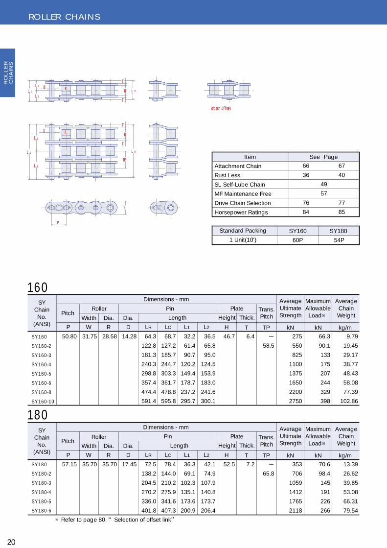
20
S YC hain
No.(ANS I)
Pitc h
S Y 1 8 0
S Y 1 8 0 -2
S Y 1 8 0 -3
S Y 1 8 0 -4
S Y 1 8 0 -5
S Y 1 8 0 -6
S Y 1 6 0
S Y 1 6 0 -2
S Y 1 6 0 -3
S Y 1 6 0 -4
S Y 1 6 0 -5
S Y 1 6 0 -6
S Y 1 6 0 -8
S Y 1 6 0 -1 0
P W R
57.15 35.70 35.70 17.45 72.5
138.2
204.5
270.2
336.0
401.8
78.4
144.0
210.2
275.9
341.6
407.3
36.3
69.1
102.3
135.1
173.6
200.9
42.1
74.9
107.9
140.8
173.7
206.4
52.5 7.2 -
65.8
353
706
1059
1412
1765
2118
70.6
98.4
145
191
226
266
13.39
26.62
39.85
53.08
66.31
79.54
R oller
Width Dia.
D
Dia.
Dimensions - mm
Pin Plate
Length Height Thic k.
Trans .Pitc h
AverageUltimateS trength
MaximumAllowable
Load※
AverageC hain
Weight
LR LC L1 L2 H T TP kN kN kg/m
S YC hain
No.(ANS I)
Pitc h
P W R
50.80 31.75 28.58 14.28 64.3
122.8
181.3
240.3
298.8
357.4
474.4
591.4
68.7
127.2
185.7
244.7
303.3
361.7
478.8
595.8
32.2
61.4
90.7
120.2
149.4
178.7
237.2
295.7
36.5
65.8
95.0
124.5
153.9
183.0
241.6
300.1
46.7 6.4 -
58.5
275
550
825
1100
1375
1650
2200
2750
66.3
90.1
133
175
207
244
329
398
9.79
19.45
29.17
38.77
48.43
58.08
77.39
102.86
R oller
Width Dia.
D
Dia.
Dimensions - mm
Pin Plate
Length Height Thic k.
Trans .Pitc h
AverageUltimateS trength
MaximumAllowable
Load※
AverageC hain
Weight
LR LC L1 L2 H T TP kN kN kg/m
16 0
18 0
※R efer to page 80. “S elec tion of offset link”
66 67
36 40
49
57
76 77
84 85
S tandard Pac king
1 Unit(10') 60P 54P
S Y 160
Item S ee P age
S Y 180
Attac hment C hain
R ust Less
S L S elf-Lube C hain
MF Maintenanc e Free
Drive C hain S elec tion
Horsepower R atings
RO
LL
ER
CH
AIN
S
H
P
T
L RW
T
L R
T
W
T
TP
RD
L 1
L C
L 2
L C
L 2
L 1 D R
2Pitch Offset
H
P
T
L RW
T
L R
T
W
T
TP
RD
L 1
L C
L 2
L C
L 2
L 1 D R
2Pitch Offset
H
P
T
L RW
T
L R
T
W
T
TP
RD
L 1
L C
L 2
L C
L 2
L 1 D R
2Pitch Offset
H
P
T
L RW
T
L R
T
W
T
TP
RD
L 1
L C
L 2
L C
L 2
L 1 D R
2Pitch Offset
H
P
T
L RW
T
L R
T
W
T
TP
RD
L 1
L C
L 2
L C
L 2
L 1 D R
2Pitch Offset
H
P
T
L RW
T
L R
T
W
T
TP
RD
L 1
L C
L 2
L C
L 2
L 1 D R
2Pitch Offset
H
P
T
L RW
T
L R
T
W
T
TP
RD
L 1
L C
L 2
L C
L 2
L 1 D R
2Pitch Offset
H
P
T
L RW
T
L R
T
W
T
TP
RD
L 1
L C
L 2
L C
L 2
L 1 D R
2Pitch Offset

RO LLER CH AIN S
21
S YC hain
No.(ANS I)
Pitc h
S Y 2 4 0
S Y 2 4 0 -2
S Y 2 4 0 -3
S Y 2 4 0 -4
S Y 2 4 0 -5
S Y 2 4 0 -6
P W R
76.20 47.63 47.63 23.78 96.4
184.2
272.0
359.8
447.6
535.5
104.1
191.8
279.6
367.4
455.2
543.0
48.2
92.1
136.0
179.9
223.8
267.8
55.9
99.7
143.6
187.5
231.4
275.2
70.3 9.5 -
87.8
677
1354
2031
2708
3385
4062
112.8
167
245
324
383
451
23.64
47.13
70.61
94.09
117.56
141.06
R oller
Width Dia.
D
Dia.
Dimensions - mm
Pin Plate
Length Height Thic k.
Trans .Pitc h
AverageUltimateS trength
MaximumAllowable
Load※
AverageC hain
Weight
LR LC L1 L2 H T TP kN kN kg/m
S YC hain
No.(ANS I)
Pitc h
S Y 2 0 0
S Y 2 0 0 -2
S Y 2 0 0 -3
S Y 2 0 0 -4
S Y 2 0 0 -5
S Y 2 0 0 -6
P W R
63.50 38.10 39.67 19.83 78.5
150.2
221.7
293.3
365.5
437.1
87.0
158.7
230.2
302.4
374.0
445.6
39.3
75.1
110.9
146.7
182.8
218.6
47.7
83.6
119.3
155.7
191.2
227.0
59.8 8.0 -
71.6
451
902
1353
1804
2255
2706
82.3
122
179
236
279
329
16.93
33.73
50.53
67.34
84.14
100.94
R oller
Width Dia.
D
Dia.
Dimensions - mm
Pin Plate
Length Height Thic k.
Trans .Pitc h
AverageUltimateS trength
MaximumAllowable
Load※
AverageC hain
Weight
LR LC L1 L2 H T TP kN kN kg/m
2 0 0
2 4 0
※R efer to page 80. “S elec tion of offset link”
40
57
76 77
85
S tandard Pac king
1 Unit(10') 48P 40P
S Y 200
Item S ee P age
S Y 240
R ust Less
MF Maintenanc e Free
Drive C hain S elec tion
Horsepower R atings
RO
LL
ER
CH
AIN
S
H
P
T
L RW
T
L R
T
W
T
TP
RD
L 1
L C
L 2
L C
L 2
L 1 D R
2Pitch Offset
H
P
T
L RW
T
L R
T
W
T
TP
RD
L 1
L C
L 2
L C
L 2
L 1 D R
2Pitch Offset

BS Straight Sidebar Chains
S YC hain
No.Pitc h
0 6 B -F
0 8 B -F
1 0 B -F
1 2 B -F
1 6 B -F
2 0 B -F
2 4 B -F
2 8 B -F
3 2 B -F
P W R
9.525
12.70
15.875
19.05
25.40
31.75
38.10
44.45
50.80
5.72
7.75
9.65
11.68
17.02
19.56
25.40
30.99
30.99
6.35
8.51
10.16
12.07
15.88
19.05
25.40
27.94
29.21
3.28
4.45
5.08
5.72
8.26
10.16
14.63
15.88
17.81
12.6
16.7
19.0
22.0
35.1
40.2
53.4
65.1
65.0
13.4
18.0
20.7
23.6
38.2
44.0
58.1
70.5
71.1
6.3
8.4
9.5
11.0
17.6
20.1
26.7
32.6
32.5
7.1
9.6
11.2
12.6
20.5
23.9
31.4
37.9
38.6
8.2
11.8
14.7
16.1
20.3
26.0
33.4
36.6
41.7
1.0 8.92
17.8
22.3
28.9
60.8
95.1
161.0
201.0
250.0
8.92
17.8
22.3
28.9
60.8
95.1
161.0
201.0
250.0
1.77
3.14
4.90
7.06
12.6
19.6
27.5
34.3
39.2
0.48
0.68
0.99
1.27
2.9
4.21
8.16
10.37
11.11
R oller
Width Dia.
D
Dia.
Dimensions - mm
Pin Plate
Length Height Thic kness
Trans .Pitc h
MinimumUltimateS trength
MaximumAllowable
Load
AverageC hain
Weight
LR LC L1 L2 H T1 T2 TP kN kN kg/m
1.5
1.65
1.8
3.2
3.5
4.8
6.3
6.3
4.0
4.5
5.9
7.4
6.9
1.25
SY BS straight sidebar chains are identical with BS standard chains except for the straight side plates. Provided with higher fatigue resistance than the standard chains. Sprockets for BS standard chains may be used for these chains. For identification, a suffix of F is added to the standard chain numbers as listed below.
RO LLER CH AIN S
Typeof
C onnLink
S pc I
C
22
RO
LL
ER
CH
AIN
S
T
L RW
T
L C
L 2
L 1 D R
P
H
T
L RW
T
L C
L 2
L 1 D R
P
H
T 12
2T 1

RO LLER CH AIN S
AN SI Straight Sidebar Chains
S YC hain
No.
Pitc h
S Y 3 5 F
S Y 4 0 F
S Y 5 0 F
S Y 6 0 F
S Y 8 0 F
S Y 1 0 0 F
S Y 1 2 0 F
S Y 1 4 0 F
S Y 1 6 0 F
S Y 2 0 0 F
S Y 2 4 0 F
P W R
9.525
12.70
15.875
19.05
25.40
31.75
38.10
44.45
50.80
63.50
76.20
4.78
7.95
9.53
12.70
15.88
19.05
25.40
25.40
31.75
38.1
47.63
5.08
7.92
10.16
11.91
15.88
19.05
22.23
25.40
28.58
39.67
47.63
3.58
3.96
5.08
5.95
7.93
9.53
11.1
12.7
14.28
19.83
23.78
12.0
16.5
20.4
25.5
32.8
39.4
49.5
54.0
64.3
78.5
96.4
12.9
17.7
21.9
26.9
35.0
43.0
53.4
58.3
68.7
87.0
104.1
6.0
8.3
10.2
12.8
16.4
19.7
24.8
27.0
32.2
39.3
48.2
6.9
9.4
11.7
14.1
18.6
23.3
28.6
31.3
36.5
47.7
55.9
9.0
11.7
14.6
17.5
23.4
29.3
35.1
40.9
46.7
59.8
70.3
1.25
1.5
2.0
2.4
3.2
4.0
4.8
5.6
6.4
8.0
9.5
10.8
19.1
31.9
43.1
78.5
118
167
216
275
451
677
2.23
4.17
7.22
10.7
18.4
28.3
38.0
50.3
66.3
82.3
112.8
0.38
0.67
1.1
1.63
2.82
4.37
6.45
8.29
10.96
18.96
26.47
R oller
Width Dia.
D
Dia.
Dimensions - mm
Pin Plate
Length Height Thic k.
AverageUltimateS trength
MaximumAllowable
Load
AverageC hain
Weight
LR LC L1 L2 H T kN kN kg/m
SY AN SI straight sidebar chains are identical with AN SI standard chains except for the straight side plates. Provided with higher fatigue resistance than the standard chains.Sprockets for AN SI standard chains may be used for these chains. For identification, a suffix of F is added to the standard chain numbers as listed below.
Typeof
C onnLink
S pc I
C
23
RO
LL
ER
CH
AIN
S
T
L RW
T
L C
L 2
L 1 D R
P
H
T
L RW
T
L C
L 2
L 1 D R
P
H

RO LLER CH AIN S
H eavy Series Roller Chains (H Series)
24
S I N G L E S T R A N D S
SY H -series roller chains are provided with greater shock and wear resistance and high breaking strength for general purpose applications. The side plate thickness is equal to the next larger AN SI roller chains and through-hardened high-tensile structural steel pins realize strong power transmis-sion in limited equipment space, showing excellent shock absorption and fatigue strength and high ultimate strength of as much as 110-120 percent.Single roller chains of this series run on standard single roller chain sprockets.
S YC hain
No.
Pitc h
S Y 6 0 H
S Y 8 0 H
S Y 1 0 0 H
S Y 1 2 0 H
S Y 1 4 0 H
S Y 1 6 0 H
S Y 1 8 0 H
S Y 2 0 0 H
S Y 2 4 0 H
P W R
19.05
25.40
31.75
38.10
44.45
50.80
57.15
63.50
76.20
12.70
15.88
19.05
25.40
25.40
31.75
35.70
38.10
47.63
11.91
15.88
19.05
22.23
25.40
28.58
35.70
39.67
47.63
5.95
7.93
9.53
11.10
12.70
14.28
17.45
19.83
23.78
28.8
35.7
42.4
52.8
57.2
67.9
75.6
84.8
109.8
30.8
38.7
45.9
57.2
61.8
73.0
81.5
93.4
118.2
14.4
17.9
21.2
26.4
28.6
34.0
37.8
42.4
54.9
16.4
20.8
24.7
30.8
33.2
39.0
43.7
51.0
63.3
17.5
23.4
29.3
35.1
40.9
46.7
52.5
59.8
70.3
3.2
4.0
4.8
5.6
6.4
7.2
8.0
9.5
12.7
54.9
90.2
137
186
241
306
373
520
726
10.7
18.4
28.3
38.0
50.3
66.3
70.6
82.3
112.8
1.80
2.81
4.14
5.83
8.41
10.86
15.18
17.85
32.29
R oller
Width Dia.
D
Dia.
Dimensions - mm
Pin Plate
Length Height Thic k.
AverageUltimateS trength
MaximumAllowable
Load
AverageC hain
Weight
LR LC L1 L2 H T kN kN kg/m
Typeof
C onnLink
S
C
RO
LL
ER
CH
AIN
S
※R efer to page 80. “S elec tion of offset link”
P
H
T
L RW
T
L R
T
W
T
RD
L C
L C
L 2
L 1 D R
P
H
T
L RW
T
L R
T
W
T
RD
L C
L C
L 2
L 1 D R
TP
TP

RO LLER CH AIN S
25
S YC hain
No.
Pitc h
S Y 6 0 H -2
S Y 6 0 H -3
S Y 6 0 H -4
S Y 8 0 H -2
S Y 8 0 H -3
S Y 8 0 H -4
S Y 8 0 H -5
S Y 8 0 H -6
S Y 8 0 H -8
S Y 1 0 0 H -2
S Y 1 0 0 H -3
S Y 1 0 0 H -4
S Y 1 0 0 H -5
S Y 1 0 0 H -6
S Y 1 0 0 H -8
S Y 1 0 0 H -1 0
S Y 1 2 0 H -2
S Y 1 2 0 H -3
S Y 1 2 0 H -4
S Y 1 2 0 H -5
S Y 1 2 0 H -6
S Y 1 2 0 H -8
S Y 1 2 0 H -1 0
S Y 1 4 0 H -2
S Y 1 4 0 H -3
S Y 1 4 0 H -4
S Y 1 4 0 H -5
S Y 1 4 0 H -6
S Y 1 4 0 H -8
S Y 1 6 0 H -2
S Y 1 6 0 H -3
S Y 1 6 0 H -4
S Y 1 6 0 H -6
S Y 1 8 0 H -2
S Y 1 8 0 H -3
S Y 1 8 0 H -4
S Y 2 0 0 H -2
S Y 2 0 0 H -3
S Y 2 0 0 H -4
S Y 2 4 0 H -2
S Y 2 4 0 H -3
S Y 2 4 0 H -4
P W R
19.05
25.40
31.75
38.10
44.45
50.8
57.15
63.50
76.20
12.70
15.88
19.05
25.40
25.40
31.75
35.70
38.10
47.63
11.91
15.88
19.05
22.23
25.40
28.58
35.70
39.67
47.63
5.95
7.93
9.53
11.10
12.70
14.28
17.45
19.84
23.78
54.9
80.6
107.1
68.4
101.0
133.6
166.2
198.8
264.0
81.6
120.7
159.4
198.5
238.2
316.4
394.6
102.0
150.6
199.2
247.8
297.6
395.4
493.2
109.4
161.8
214.0
266.2
318.4
422.8
129.8
191.8
253.7
377.5
144.2
212.8
281.4
163.1
241.4
319.8
211.0
312.2
413.4
57.0
83.1
109.3
71.3
104.0
136.7
169.3
201.9
267.1
85.0
124.4
163.2
202.3
241.8
320.0
398.2
106.1
154.6
203.2
252.6
301.9
399.7
497.5
114.0
166.4
218.7
270.9
323.1
427.5
134.9
196.8
258.8
382.6
149.8
218.7
287.4
172.0
250.3
328.4
219.4
320.6
421.8
27.4
40.3
53.6
34.2
50.5
66.8
83.1
99.4
132.0
40.8
60.4
79.7
99.3
119.1
158.2
197.3
51.0
75.3
99.6
123.9
148.8
197.7
246.6
54.7
80.9
107.0
133.1
159.2
211.4
64.9
95.9
126.9
188.8
72.1
106.4
140.7
81.6
120.7
159.9
105.5
156.1
206.7
29.6
42.8
55.7
37.1
53.5
69.9
86.2
102.5
135.1
44.2
64.0
83.5
103.0
122.7
161.8
200.9
55.1
79.3
103.6
128.7
153.1
202.0
250.9
59.3
85.5
111.7
137.8
163.9
216.1
70.0
100.9
131.9
193.8
77.7
112.3
146.7
90.4
129.6
168.7
113.9
164.5
215.1
17.5
23.4
29.3
35.1
40.9
46.7
52.5
59.8
70.3
3.2
4.0
4.8
5.6
6.4
7.2
8.0
9.5
12.7
26.1
32.6
39.1
48.9
52.2
61.9
68.6
78.3
101.2
110
165
220
180
271
361
451
541
722
274
414
548
685
822
1096
1370
372
558
744
930
1116
1488
1860
482
723
964
1205
1446
1928
612
918
1224
1836
746
1119
1492
1040
1560
2080
1452
2178
2904
15.2
22.3
29.4
25.8
38.0
50.2
59.3
69.9
94.2
39.1
57.5
75.9
89.7
106
143
173
53.4
78.5
104
123
144
195
236
70.0
103
136
161
190
255
93.3
137
181
253
102
149
197
127
186
246
173
255
336
3.59
5.39
7.18
5.54
8.26
10.98
13.71
16.43
21.88
8.20
12.26
16.33
20.39
24.45
32.58
40.70
11.56
17.29
23.02
28.75
34.48
45.94
57.40
16.59
24.77
32.96
41.15
49.33
65.78
21.21
31.54
41.89
62.58
31.06
44.94
59.83
35.20
62.53
69.94
62.06
91.82
121.58
R oller
Width Dia.
D
Dia.
Dimensions - mm
Pin Plate
Length Height Thic k.
Trans .Pitc h
AverageUltimateS trength
MaximumAllowable
Load
AverageC hain
Weight
LR LC L1 L2 H T TP kN kN kg/m
M U L T I P L E S T R A N D S
RO
LL
ER
CH
AIN
S

RO LLER CH AIN S
O il-Field Chains (E Series)
26
S YC hain
No.
Pitc h
S Y 8 0 E
S Y 8 0 E -2
S Y 8 0 E -3
S Y 8 0 E -4
S Y 8 0 E -5
S Y 8 0 E -6
S Y 8 0 E -8
S Y 1 0 0 E
S Y 1 0 0 E -2
S Y 1 0 0 E -3
S Y 1 0 0 E -4
S Y 1 0 0 E -5
S Y 1 0 0 E -6
S Y 1 0 0 E -8
S Y 1 0 0 E -1 0
S Y 1 2 0 E
S Y 1 2 0 E -2
S Y 1 2 0 E -3
S Y 1 2 0 E -4
S Y 1 2 0 E -5
S Y 1 2 0 E -6
S Y 1 2 0 E -8
S Y 1 2 0 E -1 0
P W R
25.4
31.75
38.10
15.88
19.05
25.40
15.88
19.05
22.23
7.93
9.53
11.10
32.8
61.6
90.9
120.4
149.8
179.1
237.6
39.4
75.1
110.9
147.4
183.0
218.8
290.4
362.0
49.5
94.9
140.3
186.1
231.5
276.9
367.5
458.3
35.5
64.5
94.1
123.5
152.8
182.1
240.6
43.0
78.8
114.6
150.8
186.6
222.4
294.1
365.7
53.4
98.8
144.2
190.0
235.4
280.8
371.7
462.5
16.4
30.8
45.5
60.2
74.9
89.6
118.8
19.7
37.6
55.5
73.7
91.5
109.4
145.2
181.0
24.8
47.5
70.2
93.1
115.8
138.5
183.8
229.2
19.1
33.7
48.6
63.3
77.9
92.5
121.8
23.3
41.2
59.1
77.1
95.1
113.0
148.9
184.7
28.6
51.3
74.0
96.9
119.6
142.3
187.9
233.3
23.4
29.3
35.1
3.2
4.0
4.8
-
29.3
-
35.8
-
45.4
79.4
159
238
318
397
476
635
119
238
357
476
595
714
952
1190
174
348
522
696
870
1044
1392
1740
18.4
26.7
39.3
51.8
61.2
72.2
97.3
28.3
40.8
60.0
79.2
93.6
110
149
180
38.0
54.2
79.8
105
124
147
198
239
2.52
5.10
7.68
10.25
12.84
15.42
20.58
3.91
7.74
11.58
15.40
19.26
23.10
30.81
38.54
5.76
11.49
17.20
22.92
28.65
34.36
45.81
57.38
R oller
Width Dia.
D
Dia.
Dimensions - mm
Pin Plate
Length Height Thic k.
Trans .Pitc h
AverageUltimateS trength
MaximumAllowable
Load
AverageC hain
Weight
LR LC L1 L2 H T TP kN kN kg/m
SY O il-field chains are manufactured in ac-cordance with AN SI, API standards, and of-ficially approved by The American Petrole-um Institute for high quality , reliability and long trouble-free service life. U sed in oil-field drilling and producing operations such as hoisting, pumping and drawworks.SY E & H E-series roller chains are manufac-tured in the same standards as O il-field chains.
E T Y P E
RO
LL
ER
CH
AIN
S
※R efer to page 80. “S elec tion of offset link”
H
P
T
L RW
T
L R
T
W
T
RD
L C
L C
L 2
L 1 D R
H
P
T
L RW
T
L R
T
W
T
RD
L C
L C
L 2
L 1 D R
H
P
H
P
H
P
T
L RW
T
L R
T
W
T
RD
L C
L C
L 2
L 1 D R
H
P
T
L RW
T
L R
T
W
T
RD
L C
L C
L 2
L 1 D R
H
P
H
P
TP
TP
RO LLER CH AIN S
27
S YC hain
No.
Pitc h
S Y 1 4 0 E
S Y 1 4 0 E -2
S Y 1 4 0 E -3
S Y 1 4 0 E -4
S Y 1 4 0 E -5
S Y 1 4 0 E -6
S Y 1 4 0 E -8
S Y 1 6 0 E
S Y 1 6 0 E -2
S Y 1 6 0 E -3
S Y 1 6 0 E -4
S Y 1 6 0 E -6
S Y 1 8 0 E
S Y 1 8 0 E -2
S Y 1 8 0 E -3
S Y 1 8 0 E -4
S Y 2 0 0 E
S Y 2 0 0 E -2
S Y 2 0 0 E -3
S Y 2 0 0 E -4
S Y 2 4 0 E
S Y 2 4 0 E -2
S Y 2 4 0 E -3
S Y 2 4 0 E -4
P W R
44.45
50.80
57.15
63.50
76.20
25.40
31.75
35.70
38.10
47.63
25.40
28.58
35.70
39.67
47.63
12.70
14.28
17.45
19.83
23.78
54.0
102.9
151.7
201.2
250.1
299.0
396.5
64.3
122.8
181.3
240.3
298.8
72.5
138.2
204.5
270.2
78.5
150.2
221.7
293.3
96.4
184.2
272.0
359.8
58.3
107.2
156.3
205.5
254.4
303.3
401.1
68.7
127.2
185.7
244.7
303.3
78.4
144.0
210.2
275.9
87.0
158.7
230.2
302.4
104.1
191.8
279.6
367.4
27.0
51.5
75.9
100.6
125.1
149.5
198.3
32.2
61.4
90.7
120.2
149.4
36.3
69.1
102.3
135.1
39.3
75.1
110.9
146.7
48.2
92.1
136.0
179.9
31.3
55.7
80.4
104.9
129.3
153.8
202.8
36.5
65.8
95.0
124.5
153.9
42.1
74.9
107.9
140.8
47.7
83.6
119.3
155.7
55.9
99.7
143.6
187.5
40.9
46.7
52.5
59.8
70.3
5.6
6.4
7.2
8.0
9.5
-
48.9
-
58.5
-
65.8
-
71.6
-
87.8
227
454
681
908
1135
1362
1816
294
588
882
1176
1764
363
726
1089
1452
470
940
1410
1880
677
1354
2031
2708
50.3
73.2
108
142
168
198
267
66.3
95.0
140
184
257
70.6
102
150
197
82.3
130
191
252
112.8
179
263
347
7.41
14.63
21.91
29.17
36.45
43.72
58.28
9.79
19.45
29.17
38.77
58.08
13.39
26.62
39.85
53.08
16.93
33.73
50.53
67.34
23.64
47.13
70.61
94.09
R oller
Width Dia.
D
Dia.
Dimensions - mm
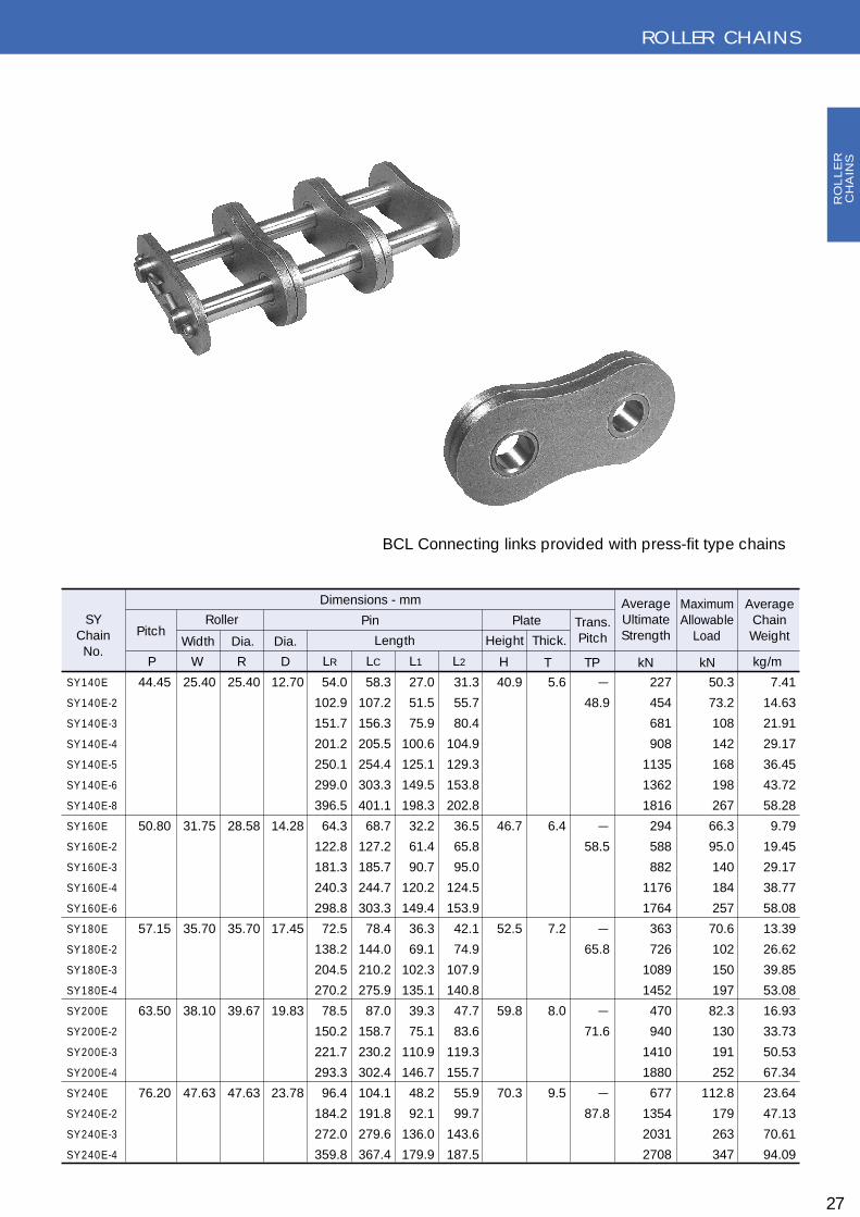
B C L C onnec ting links provided with press-fit type c hains
Pin Plate
Length Height Thic k.
Trans .Pitc h
AverageUltimateS trength
MaximumAllowable
Load
AverageC hain
Weight
LR LC L1 L2 H T TP kN kN kg/m
RO
LL
ER
CH
AIN
S

RO LLER CH AIN S
O IL-FIELD CH AIN S(H E SERIES)
28
S YC hain
No.
Pitc h
S Y 8 0 H E
S Y 8 0 H E -2
S Y 8 0 H E -3
S Y 8 0 H E -4
S Y 8 0 H E -5
S Y 8 0 H E -6
S Y 8 0 H E -8
S Y 1 0 0 H E
S Y 1 0 0 H E -2
S Y 1 0 0 H E -3
S Y 1 0 0 H E -4
S Y 1 0 0 H E -5
S Y 1 0 0 H E -6
S Y 1 0 0 H E -8
S Y 1 0 0 H E -1 0
S Y 1 2 0 H E
S Y 1 2 0 H E -2
S Y 1 2 0 H E -3
S Y 1 2 0 H E -4
S Y 1 2 0 H E -5
S Y 1 2 0 H E -6
S Y 1 2 0 H E -8
S Y 1 2 0 H E -1 0
P W R
25.4
31.75
38.10
15.88
19.05
25.40
15.88
19.05
22.23
7.93
9.53
11.10
35.5
68.4
101.0
133.6
166.2
199.0
264.0
42.2
81.6
120.7
159.0
198.5
238.2
316.4
394.6
52.6
102.0
150.6
199.2
247.8
297.6
395.4
493.2
38.8
71.3
104.0
136.7
169.3
201.9
267.1
45.7
85.0
124.4
163.5
202.3
241.8
320.0
398.2
57.0
106.1
154.6
203.7
252.6
301.5
399.7
497.5
17.8
34.2
50.5
66.8
83.1
99.4
132.0
21.1
40.8
60.4
79.7
99.3
119.1
158.2
197.3
26.3
51.0
75.3
99.6
123.9
148.8
197.7
246.6
21.1
37.1
53.5
69.9
86.2
102.5
135.1
24.6
44.2
64.0
83.5
103.0
122.7
161.8
200.9
30.7
55.1
79.3
104.1
128.7
152.7
202.0
250.9
23.4
29.3
35.1
4.0
4.8
5.6
-
32.6
-
39.1
-
48.9
93.2
186
280
373
466
559
746
142
284
426
568
710
852
1136
1420
191
382
573
764
955
1146
1528
1910
18.4
28.4
41.8
55.1
65.1
76.8
104
28.3
45.1
66.3
87.5
103
122
164
199
38.0
58.3
85.8
113
134
158
213
257
2.80
5.54
8.26
10.98
13.71
16.43
21.88
4.14
8.20
12.26
16.33
20.39
24.45
32.58
40.70
5.83
11.56
17.29
23.02
28.75
34.48
45.94
57.40
R oller
Width Dia.
D
Dia.
Dimensions - mm
Pin Plate
Length Height Thic k.
Trans .Pitc h
AverageUltimateS trength
MaximumAllowable
Load
AverageC hain
Weight
LR LC L1 L2 H T TP kN kN kg/m
H E T Y P E
SY H eavy series roller chains are designed with thicker side plates to insure greater capacity for absorbing shock loads without fatigue failure of side plates. Also manufactured to close tolerances in accordance with AN SI specifications and are mainly used for applications where space and design limitations prohibit the use of a large size roller chain, and yet greater load carrying capacities are needed in oil-field drilling operations.
H
P
T
L RW
T
L R
T
W
T
RD
L C
L C
L 2
L 1 D R
H
P
T
L RW
T
L R
T
W
T
RD
L C
L C
L 2
L 1 D R
H
P
H
P
H
P
T
L RW
T
L R
T
W
T
RD
L C
L C
L 2
L 1 D R
H
P
T
L RW
T
L R
T
W
T
RD
L C
L C
L 2
L 1 D R
H
P
H
P
TP
TP
RO
LL
ER
CH
AIN
S
※R efer to page 80. “S elec tion of offset link”

RO LLER CH AIN S
29
S YC hain
No.
Pitc h
S Y 1 4 0 H E
S Y 1 4 0 H E -2
S Y 1 4 0 H E -3
S Y 1 4 0 H E -4
S Y 1 4 0 H E -5
S Y 1 4 0 H E -6
S Y 1 4 0 H E -8
S Y 1 6 0 H E
S Y 1 6 0 H E -2
S Y 1 6 0 H E -3
S Y 1 6 0 H E -4
S Y 1 6 0 H E -6
S Y 1 8 0 H E
S Y 1 8 0 H E -2
S Y 1 8 0 H E -3
S Y 1 8 0 H E -4
S Y 2 0 0 H E
S Y 2 0 0 H E -2
S Y 2 0 0 H E -3
S Y 2 0 0 H E -4
S Y 2 4 0 H E
S Y 2 4 0 H E -2
S Y 2 4 0 H E -3
S Y 2 4 0 H E -4
P W R
44.45
50.80
57.15
63.50
76.20
25.40
31.75
35.70
38.10
47.63
25.40
28.58
35.70
39.67
47.63
12.70
14.28
17.45
19.83
23.78
57.0
109.4
161.8
214.0
266.2
318.4
422.8
67.7
129.8
191.8
253.7
377.5
75.7
144.2
212.8
281.4
84.9
163.1
241.4
319.8
110.2
211.6
312.6
414.0
61.6
114.0
166.4
218.7
270.9
323.1
427.5
72.9
134.9
196.8
258.8
382.6
81.3
149.8
218.7
287.4
93.2
172.0
250.3
328.6
117.7
218.9
320.1
421.3
28.5
54.7
80.9
107.0
133.1
159.2
211.4
33.9
64.9
95.9
126.9
188.8
37.9
72.1
106.4
140.7
42.5
81.6
120.7
159.9
55.6
105.8
156.3
207.0
33.1
59.3
85.5
111.7
137.8
163.9
216.1
39.1
70.0
100.9
131.9
193.8
43.5
77.7
112.3
146.7
50.8
90.4
129.6
168.7
62.0
113.1
163.8
214.3
40.9
46.7
52.5
59.8
70.3
6.4
7.2
8.0
9.5
12.7
52.2
61.9
68.6
78.3
101.2
252
504
756
1008
1260
1512
2016
319
638
957
1276
1914
441
882
1323
1764
559
1118
1677
2236
883
1766
2649
3532
50.3
76.7
113
149
176
207
280
66.3
100.
147
194
270
70.6
121
179
236
82.3
138
204
269
112.8
192
283
373
8.41
16.59
24.77
32.96
41.15
49.33
65.78
10.86
21.21
31.54
41.89
62.58
15.18
30.06
44.94
59.83
17.85
35.20
52.53
69.94
32.29
62.06
91.82
121.58
R oller
Width Dia.
D
Dia.
Dimensions - mm
Pin Plate
Length Height Thic k.
Trans .Pitc h
AverageUltimateS trength
MaximumAllowable
Load
AverageC hain
Weight
LR LC L1 L2 H T TP kN kN kg/m
RO
LL
ER
CH
AIN
S

RO LLER CH AIN S
SU PER RO LLER CH AIN S
30
S YC hain
No.(ANS I)
Pitc h
S U P E R 8 0
S U P E R 1 0 0
S U P E R 1 2 0
S U P E R 1 4 0
S U P E R 1 6 0
S U P E R 2 0 0
S U P E R 2 4 0
S U P E R 8 0 H
S U P E R 1 0 0 H
S U P E R 1 2 0 H
S U P E R 1 4 0 H
S U P E R 1 6 0 H
P W R
25.40
31.75
38.10
44.45
50.80
63.50
76.20
25.40
31.75
38.10
44.45
50.80
15.88
19.05
25.40
25.40
31.75
38.10
47.63
15.88
19.05
25.40
25.40
31.75
15.88
19.05
22.23
25.40
28.58
39.67
47.63
15.88
19.05
22.23
25.40
28.58
7.93
9.53
11.10
12.70
14.28
19.83
23.78
7.93
9.53
11.10
12.70
14.28
32.6
39.8
49.7
54.0
64.4
78.6
96.4
35.9
42.6
52.8
57.2
67.9
35.5
43.2
53.7
58.3
69.0
86.2
103.4
38.9
46.2
57.3
61.9
72.8
16.3
19.9
24.9
27.0
32.2
39.3
48.2
18.0
21.3
26.4
28.6
34.0
19.2
23.3
28.8
31.3
36.8
46.9
55.2
20.9
24.9
30.9
33.3
38.8
24.1
30.1
36.2
42.2
48.2
60.3
72.4
24.1
30.1
36.2
42.2
48.2
3.2
4.0
4.8
5.6
6.4
8.0
9.5
4.0
4.8
5.6
6.4
7.1
84.3
127
186
245
314
490
726
98.1
145
196
255
324
18.6
30.4
39.2
53.9
70.6
94.1
132
20.6
32.4
42.2
56.9
73.5
2.81
4.26
6.30
8.04
10.8
17.6
25.6
3.33
4.88
6.94
8.87
11.7
R oller
Width Dia.
D
Dia.
Dimensions - mm
Pin Plate
Length Height Thic k.
AverageUltimateS trength
Note: 1. Offset links are not available. 2. R iveted type c hain will be provided unless otherwise spec ified. C ottered type c hain will be provided upon request. 3. Press-fitted type c onnec ting links will be supplied.
MaximumAllowable
Load
AverageC hain
Weight
LR LC L1 L2 H T kN kN kg/m
S I N G L E S T R A N D S
SY Super standard series roller chains are developed to offer you longer service life , thus leading to labor-savings. Thorough consideration to fitting portions and the useof high-grade special alloy steel components ensure the chain's greater resistance of fatigue and shock. O perative on standard roller chain sprockets.SY super heavy series roller chains provided with link plates of next larger chain size promise you higher performance and superior quality.
T
L RW
T
L C
L 2
L 1 D R
P
H
T
L RW
T
L C
L 2
L 1 D R
P
H
RO
LL
ER
CH
AIN
S

RO LLER CH AIN S
31
S YC hain
No.Pitc h
S U P E R 8 0 -2
S U P E R 8 0 -3
S U P E R 8 0 -4
S U P E R 1 0 0 -2
S U P E R 1 0 0 -3
S U P E R 1 0 0 -4
S U P E R 1 2 0 -2
S U P E R 1 2 0 -3
S U P E R 1 2 0 -4
S U P E R 1 4 0 -2
S U P E R 1 4 0 -3
S U P E R 1 4 0 -4
S U P E R 1 6 0 -2
S U P E R 1 6 0 -3
S U P E R 1 6 0 -4
S U P E R 2 0 0 -2
S U P E R 2 0 0 -3
S U P E R 2 0 0 -4
S U P E R 2 4 0 -2
S U P E R 2 4 0 -3
S U P E R 2 4 0 -4
S U P E R 8 0 H -2
S U P E R 8 0 H -3
S U P E R 1 0 0 H -2
S U P E R 1 0 0 H -3
S U P E R 1 2 0 H -2
S U P E R 1 2 0 H -3
S U P E R 1 4 0 H -2
S U P R R 1 4 0 H -3
S U P E R 1 6 0 H -2
S U P E R 1 6 0 H -3
P W R
25.40
31.75
38.10
44.45
50.80
63.50
76.20
25.40
31.75
38.10
44.45
50.80
15.88
19.05
25.40
25.40
31.75
38.10
47.63
15.88
19.05
25.40
25.40
31.75
15.88
19.05
22.23
25.40
28.58
39.67
47.63
15.88
19.05
22.23
25.40
28.58
7.93
9.53
11.10
12.70
14.28
19.83
23.78
7.93
9.53
11.10
12.70
14.28
62.0
91.3
120.6
75.4
111.2
147.0
95.4
140.8
186.2
103.3
152.2
201.1
123.2
181.7
240.2
150.6
222.2
293.8
184.2
272.0
359.8
68.6
101.2
81.6
120.7
102.0
150.9
109.6
161.8
223.7
285.6
64.9
94.2
123.5
79.0
114.8
150.6
99.4
144.8
190.2
107.6
156.5
205.4
127.8
186.3
244.8
158.2
229.8
301.4
191.2
279.0
366.8
399.4
432.0
85.4
124.5
173.4
222.3
274.5
326.7
388.6
450.5
31.0
45.7
60.3
37.7
55.6
73.5
47.7
70.4
93.1
51.7
76.1
100.6
61.6
90.9
120.1
75.3
111.1
146.9
92.1
136.0
179.9
34.3
50.6
40.8
60.4
51.0
75.5
54.8
80.9
111.9
142.8
33.9
48.5
63.2
41.3
59.2
77.1
51.7
74.4
97.1
55.9
80.4
104.8
66.2
95.4
124.7
82.9
118.7
154.5
99.1
143.0
186.9
365.1
381.4
44.6
64.1
122.4
79.6
219.7
245.8
276.8
100.7
24.1
30.1
36.2
42.2
48.2
60.3
72.4
24.1
30.1
36.2
42.2
48.2
3.2
4.0
4.8
5.6
6.4
8.0
9.5
4.0
4.8
5.6
6.4
7.1
29.3
35.8
45.4
48.9
58.5
71.6
87.8
32.6
39.1
48.9
52.2
61.9
169
253
337
254
381
508
372
558
744
490
735
980
628
942
1256
980
1470
1960
1452
2178
2904
196.2
294.3
290
435
392
588
510
765
648
972
31.6
46.5
61.4
51.7
76.0
100
66.6
98.0
129
91.6
135
178
120
177
233
160
235
311
224
330
436
35.02
51.5
55.08
81.0
71.74
105.5
96.73
142.25
124.95
183.75
5.63
8.41
11.18
8.38
12.57
16.77
12.44
18.65
24.85
15.92
23.84
30.72
21.44
32.10
42.84
34.91
52.44
69.74
50.88
76.12
101.40
6.67
9.96
9.6
14.4
13.71
20.55
17.56
26.3
23.15
34.67
R oller
Width Dia.
D
Dia.
Dimensions - mm
Pin Plate
Length Height Thic k.
Trans .Pitc h
AverageUltimateS trength
MaximumAllowable
Load
AverageC hain
Weight
LR LC L1 L2 H T TP kN kN kg/m
M U L T I P L E S T R A N D S
RO
LL
ER
CH
AIN
S
P
H
L R
T
W
T
TP
RD
L 1
L C
L 2
P
H
L R
T
W
T
TP
RD
L 1
L C
L 2

RO LLER CH AIN S
32
D ouble Capacity ChainsD ouble Capacity Chain is a single strand chain that offers the same ultimate tensile strength as a double strand chain with a saving of 50%.D ouble Capacity Chain consists of twice the amount of side plates as single strand chain.
S YC hain
No.Pitc h
Pitc h
1 6 B D C ・T C ・F C
2 0 B D C ・T C ・F C
2 4 B D C ・T C ・F C
2 8 B D C ・T C ・F C
3 2 B D C ・T C ・F C
8 0 D C ・T C ・F C
1 0 0 D C ・T C ・F C
1 2 0 D C ・T C ・F C
1 4 0 D C ・T C ・F C
1 6 0 D C ・T C ・F C
1 8 0 D C ・T C ・F C
2 0 0 D C ・T C ・F C
2 4 0 D C ・T C ・F C
P W R
25.40
31.75
38.10
44.45
50.80
25.40
31.75
38.10
44.45
50.80
57.15
63.50
76.20
17.02
19.56
25.40
31.00
31.00
15.88
19.05
25.40
25.40
31.75
35.70
38.10
47.63
15.88
19.05
25.40
27.94
29.21
15.88
19.05
22.23
25.40
28.58
35.70
39.67
47.63
8.26
10.16
14.63
15.88
17.81
7.93
9.53
11.10
12.70
14.28
17.45
19.83
23.78
50.0
56.0
75.4
93.0
92.4
45.6
55.8
69.0
76.4
90.0
101.6
111.2
135.6
53.2
60.4
80.5
98.8
98.5
48.7
59.5
73.3
81.1
95.1
107.7
120.0
143.2
31.9
36.5
48.4
59.6
58.6
29.3
35.8
45.4
48.9
58.5
65.8
71.6
87.8
44.7
50.5
68.0
84.8
83.8
42.1
51.8
64.2
71.3
84.1
94.6
103.6
125.8
137
212
359
447
549
157
235
343
451
559
726
932
1353
205
318
538
670
823
235
352
514
676
838
1089
1398
2029
274
424
718
894
1098
314
470
686
902
1118
1452
1864
2706
19.5
30.2
51.2
63.8
78.4
22.4
33.5
49.0
64.4
79.8
103.0
133.0
193.0
R oller
Width Dia.
D
Dia.
Dimensions - mm
Pin Transverse
Length
AverageUltimateS trength
LR 1 LC 1 TP1 TP2 DC DCTC
(kN)
FC
MaximumAllowableLoad(kN)
DC(×2) TC(×3)
FC(×4)
RO
LL
ER
CH
AIN
S
W
P
L R1L C1
D
R W
P
L R1L C1
D
R
W
L R2L C2
D
R
TP 1
W
L R3L C3TP 2
D
R
W
L R2L C2
D
R
TP 1
W
L R3L C3TP 2
D
R

RO LLER CH AIN S
33
D O U B L E P I T C H T Y P E
S YC hain
No.Pitc h
2 0 4 0 D C
2 0 5 0 D C
2 0 6 0 H D C
2 0 8 0 H D C
2 1 0 0 H D C
2 1 2 0 H D C
2 1 6 0 H D C
P W R
25.40
31.75
38.10
50.80
63.50
76.20
101.60
7.95
9.53
12.70
15.88
19.05
25.40
31.75
7.92
10.16
11.91
15.88
19.05
22.23
28.58
3.96
5.08
5.95
7.93
9.53
11.10
14.28
23.0
28.8
42.2
52.0
62.0
77.8
97.4
24.7
30.5
44.2
55.1
65.6
82.1
102.6
11.5
14.4
21.1
26.0
31.0
38.9
48.7
13.2
16.1
23.1
29.1
34.6
43.2
53.9
11.4
15.0
17.0
22.6
28.6
34.9
47.6
1.5
2.0
3.2
4.0
4.8
5.6
7.2
38.2
63.8
109.8
180.4
274.0
372.0
612.0
4.02
6.72
11.56
18.99
28.84
39.16
64.42
0.50
0.85
1.46
2.50
3.81
5.50
9.27
R oller
Width Dia.
D
Dia.
Dimensions - mm
Pin Plate
Length Height Thic k.
AverageUltimateS trength
MaximumAllowable
Load
AverageC hain
Weight
LR LC L1 L2 H T kN kN kg/m
S YC hain
No.Pitc h
S Y 2 5 1 S
S Y 2 6 4 S
P W R
50.80
63.50
31.75
38.10
28.58
39.67
15.88
22.22
67.9
85.8
73.2
94.5
34.0
42.9
39.2
51.6
46.7
59.8
7.2
9.5
333
556
58.8
81.4
11.31
19.27
R oller
Width Dia.
D
Dia.
Dimensions - mm
Pin Plate
Length Height Thic k.
AverageUltimateS trength
MaximuAllowable
Load
AverageC hain
Weight
LR LC L1 L2 H T kN kN kg/m
S-SERIES RO LLER CH AIN SS-series roller chains are designed for high breaking strength and maximum endurance in pursuit of greater chain rigidity. Combination of plates one size thicker than standard's and thick, tough pins ensures accurate operations and long performance life under harsh, heavy loads. Single strand roller chains of this series run on standard single roller chain sprockets.
T
L RW
T
H
P
L C
L 1D
2L
R
T
L RW
T
H
P
L C
L 1D
2L
R
H
P
T
L RW
T
L C
L 2
L 1 D R
H
P
T
L RW
T
L C
L 2
L 1 D RR
OL
LE
RC
HA
INS

D O U BLE PITCH RO LLEER CH AIN S
D O U BLE PITCH RO LLEER CH AIN S(D RIV E SERIES)
34
D R I V E S E R I E S
S YC hain
No.(ANS I)
Pitc h
A 2 0 4 0
A 2 0 5 0
A 2 0 6 0
A 2 0 8 0
P W R
25.40
31.75
38.10
50.80
7.95
9.53
12.70
15.88
7.92
10.16
11.91
15.88
3.96
5.08
5.95
7.93
16.5
20.4
25.5
32.8
17.9
22.0
26.9
35.2
8.3
10.2
12.8
16.4
9.6
11.8
14.1
18.8
11.4
15.0
17.0
22.6
1.5
2.0
2.4
3.2
16.7
27.5
40.2
68.2
2.65
4.31
6.23
10.7
0.43
0.73
1.03
1.71
R oller
Width Dia.
D
Dia.
Dimensions - mm
Pin Plate
Length Height Thic k.
AverageUltimateS trength
MaximumAllowable
Load
AverageC hain
Weight
LR LC L1 L2 H T kN kN kg/m
D R
T
W
T
H
P
L R
D R
T
W
T
H
P
L RL C
L 1
L 2
DO
UB
LE
P
ITC
HR
OL
LE
R
CH
AIN
S

D O U BLE PITCH RO LLEER CH AIN S
D O U BLE PITCH RO LLER CH AIN S(CO N V EYO R SERIES)
35
C A R R I E R R O L L E R T Y P E
Pitc h
C 2 0 4 2
C 2 0 5 2
C 2 0 6 2 H
C 2 0 8 2 H
C 2 1 0 2 H
C 2 1 2 2 H
C 2 1 6 2 H
P W R
25.40
31.75
38.10
50.80
63.50
76.20
101.60
7.95
9.53
12.70
15.88
19.05
25.40
31.75
15.88
19.05
22.23
28.58
39.67
44.45
57.15
3.96
5.08
5.95
7.93
9.53
11.10
14.28
16.5
20.4
28.7
35.5
42.2
52.6
67.7
18.5
22.0
31.0
38.8
45.7
57.0
72.9
8.2
10.2
14.4
17.8
21.1
26.3
33.9
10.3
11.8
16.6
21.0
24.6
30.7
39.0
11.4
15.0
17.0
22.6
28.6
34.9
47.6
1.5
2.0
3.2
4.0
4.8
5.6
7.2
0.82
1.26
2.08
3.36
5.64
7.87
12.77
R oller
Width Dia.
D
Dia.
Dimensions - mm
Pin Plate
Length Height Thic k.
AverageUltimateS trength
MaximumAllowable
Load
AverageC hain
Weight
LR LC L1 L2 H T kN kN kg/m
S T A N D A R D R O L L E R T Y P E
S YC hain
No.(ANS I)
S YC hain
No.(ANS I)
Pitc h
C 2 0 4 0
C 2 0 5 0
C 2 0 6 0 H
C 2 0 8 0 H
C 2 1 0 0 H
C 2 1 2 0 H
C 2 1 6 0 H
P W R
25.40
31.75
38.10
50.80
63.50
76.20
101.60
7.95
9.53
12.70
15.88
19.05
25.40
31.75
7.92
10.16
11.91
15.88
19.05
22.23
28.58
3.96
5.08
5.95
7.93
9.53
11.10
14.28
16.5
20.4
28.7
35.5
42.2
52.6
67.7
18.5
22.0
31.0
38.8
45.7
57.0
72.9
8.2
10.2
14.4
17.8
21.1
26.3
33.9
10.3
11.8
16.6
21.0
24.6
30.7
39.0
11.4
15.0
17.0
22.6
28.6
34.9
47.6
1.5
2.0
3.2
4.0
4.8
5.6
7.2
0.48
0.82
1.38
2.32
3.46
4.92
8.02
R oller
Width Dia.
D
Dia.
Dimensions - mm
Pin Plate
Length Height Thic k.
AverageUltimateS trength
MaximumAllowable
Load
AverageC hain
Weight
LR LC L1 L2 H T kN kN kg/m
T
P
RD
D R
P
1
W
T
L R
H
L R
T
W
T
H
T
P
RD
D R
P
1
W
T
L R
H
L R
T
W
T
H
L C
L 1
L 2
L C
L 1
L 2
DO
UB
LE
P
ITC
HR
OL
LE
R
CH
AIN
S
16.9
27.5
40.2
68.6
107.9
151.0
257.9
3.63
6.28
8.63
14.7
22.6
30.4
53.0
16.9
27.5
40.2
68.6
107.9
151.0
257.9
3.63
6.28
8.63
14.7
22.6
30.4
53.0

P W R D LR LC L1 L2 H T1 / T2 kN kN kg/m
S YC hain
No.
Pitc h
P W R
R oller
Width Dia.
D
Dia.
Dimensions - mm
Pin Plate
Length Height Thic k.
MinimumUltimateS trength
MaximumAllowable
Load
AverageC hain
Weight
LR LC L1 L2 H T kN kN kg/m
RU
ST
LE
SS
CH
AIN
S
36
RU STLESS CH AIN S
Stainless Steel ChainsSS series stainless steel roller chains provide excellent corrosion protection against low or high temperature, acid, alkali, moisture, scale, oil and magnetism.SS series stainless steel roller chains are manufactured in accordance with the dimensions AN SI standards.IN TRO D U CTIO N O F SY N EW H IG H PO W ER N EW SSS SERIES PRO D U CTSSSS series stainless steel roller chains with solid rollers.Anti-magnetic of solid roller has superior permeability than the common curled roller.H igh Power N ew SSS Chain use a specially treated pin and roller.Extremely long life is engaged by this surface treatment.SSS series chain life is more than 2 times longer than that of normal SS series Chain.50% H igher Allowable Loads
0 6 B -S S
0 8 B -S S
1 0 B -S S
1 2 B -S S
1 6 B -S S
9.525
12.70
15.875
19.05
25.40
5.72
7.75
9.65
11.68
17.02
6.35
8.51
10.16
12.07
15.88
3.28
4.45
5.08
5.72
8.26
12.6
16.7
19.0
22.0
35.1
13.4
17.8
20.6
23.6
38.2
6.3
8.4
9.5
11.0
17.6
7.1
9.4
11.1
12.6
20.6
8.2
11.8
14.7
16.1
20.3
1.0/1.25
1.5
1.65
1.8
3.2/4.0
0.27
0.52
0.68
0.88
2.06
6.18
10.3
15.7
18.1
42.2
0.43
0.61
0.89
1.14
2.59
B S A N D A N S I S T A I N L E S S S T E E L C H A I N
S Y 3 5 -S S
S Y 4 0 -S S
S Y 5 0 -S S
S Y 6 0 -S S
S Y 8 0 -S S
S Y 1 0 0 -S S
※S Y 1 2 0 -S S
※S Y 1 4 0 -S S
※S Y 1 6 0 -S S
9.525
12.70
15.875
19.05
25.40
31.75
38.10
44.45
50.80
4.78
7.95
9.53
12.70
15.88
19.05
25.40
25.40
31.75
▲5.08
7.92
10.16
11.91
15.88
19.05
22.23
25.40
28.58
3.58
3.96
5.08
5.95
7.93
9.53
11.10
12.70
14.28
12.2
16.9
20.8
26.0
32.8
40.0
50.4
54.0
64.3
13.7
18.5
22.3
27.9
35.5
43.3
54.2
58.3
68.7
6.1
8.5
10.4
13.0
16.4
20.0
25.2
27.0
32.2
7.6
10.0
11.9
14.9
19.1
23.3
29.0
31.3
36.5
9.0
11.7
14.6
17.5
23.4
29.3
35.1
40.9
46.7
1.25
1.5
2.0
2.4
3.2
4.0
4.8
5.6
6.4
5.68
11.1
17.6
24.5
42.3
51.0
68.6
88.2
109.8
0.26
0.44
0.68
1.03
1.77
2.55
3.92
4.66
6.37
0.34
0.60
0.98
1.46
2.52
3.91
5.76
7.41
9.79
▲C hain is rollerless R shows bushing dia.※304 S tainless s teel.
T
L RW
T
L C
L 2
L 1 D R
P
H
T
L RW
T
L C
L 2
L 1 D R
P
H

RU STLESS CH AIN S
37
S YC hain
No.
Pitc h
A 2 0 4 0 -S S
A 2 0 5 0 -S S
A 2 0 6 0 -S S
A 2 0 8 0 -S S
C 2 0 4 0 -S S
C 2 0 5 0 -S S
C 2 0 6 0 H -S S
C 2 0 8 0 H -S S
※C 2 1 0 0 H -S S
※C 2 1 2 0 H -S S
※C 2 1 6 0 H -S S
C 2 0 4 2 -S S
C 2 0 5 2 -S S
C 2 0 6 2 H -S S
C 2 0 8 2 H -S S
※C 2 1 0 2 H -S S
※C 2 1 2 2 H -S S
※C 2 1 6 2 H -S S
P W R
25.40
31.75
38.10
50.80
25.40
31.75
38.10
50.80
63.50
76.20
101.60
25.40
31.75
38.10
50.80
63.50
76.20
101.60
7.95
9.53
12.70
15.88
7.95
9.53
12.70
15.88
19.05
25.40
31.75
7.95
9.53
12.70
15.88
19.05
25.40
31.75
7.92
10.16
11.91
15.88
7.92
10.16
11.91
15.88
19.05
22.23
28.58
15.88
19.05
22.23
28.58
39.67
44.45
57.15
3.96
5.08
5.95
7.93
3.96
5.08
5.95
7.93
9.53
11.10
14.28
3.96
5.08
5.95
7.93
9.53
11.10
14.28
16.9
20.8
26.0
32.8
16.9
20.8
28.8
35.7
42.4
52.8
67.9
16.9
20.8
28.8
35.7
42.4
52.8
67.9
18.5
22.3
27.9
35.5
18.5
22.3
30.9
38.8
46.0
57.2
73.1
18.5
22.3
30.9
38.8
46.0
57.2
73.1
8.5
10.4
13.0
16.4
8.5
10.4
14.4
17.9
21.2
26.4
34.0
8.5
10.4
14.4
17.9
21.2
26.4
34.0
10.0
11.9
14.9
19.1
10.0
11.9
16.5
20.9
24.8
30.8
39.1
10.0
11.9
16.5
20.9
24.8
30.8
39.1
11.4
15.0
17.0
22.6
11.4
15.0
17.0
22.6
28.6
34.9
47.6
11.4
15.0
17.0
22.6
28.6
34.9
47.6
1.5
2.0
2.4
3.2
1.5
2.0
3.2
4.0
4.8
5.6
7.2
1.5
2.0
3.2
4.0
4.8
5.6
7.2
12.4
20.3
27.4
47.1
12.4
20.3
27.4
47.1
56.9
76.5
123
12.4
20.3
27.4
47.1
56.9
76.5
123
0.44
0.68
1.03
1.77
0.44
0.68
1.03
1.77
2.55
3.92
6.37
0.44
0.68
1.03
1.77
2.55
3.92
6.37
0.43
0.73
1.03
1.71
0.48
0.82
1.38
2.32
3.46
4.92
8.02
0.82
1.26
2.08
3.36
5.64
7.87
12.77
R oller
Width Dia.
D
Dia.
Dimensions - mm
Pin Plate
Length Height Thic k.
AverageUltimateS trength
MaximumAllowable
Load
AverageC hain
Weight
LR LC L1 L2 H T kN kN kg/m
D O U B L E P I T C H S T A I N L E S S S T E E L C H A I N
※304 S tainless s teel
D R
T
W
T
H
P
L R
T
T
W
H
P
RDL R
T
W
T
H
L R
D R
P
L C
L
L
L C
L 2
L 1
L C
L 2
L 1
D R
T
W
T
H
P
L R
T
T
W
H
P
RDL R
T
W
T
H
L R
D R
P
L C
L 1
L 2
L C
L 1
L 2
L C
L 1
L 2
RU
ST
LE
SS
CH
AIN
S

RU
ST
LE
SS
CH
AIN
S
38
RU STLESS CH AIN S
Selection of Stainless Steel Chain
S e r v ic e F a c t o r ( f1 )(f1)C ondition
S mooth
S ome Impac t
Large Impac t
1.0
1.2
1.5
S e r v ic e F a c t o r ( f2 )(f2)C hain S peed (m/s )
0 - 15
15 - 30
30 - 50
50 - 70
1.0
1.2
1.4
1.6
S e r v ic e F a c t o r ( f4 )(f4)C orros ion R ating
1
2
3
4
1.00
1.23
1.44
×
S e r v ic e F a c t o r ( f5 )(f5)L ubric ation
Lubric ate
dry
1.00
1.44
S e r v ic e F a c t o r ( f3 )316S S 600304S ST emperature (°C )
-40 to-20
-20 - 400
400 - 500
500 - 600
600 - 700
700 - 800
1.0
1.0
1.2
1.5
1.8
2.0
×:Not R ec ommended
×
1.0
1.8
×
×
×
1.0
1.0
1.2
1.5
1.8
×
Chain selection should be made based on the bearing pressure as shown below
Max. Allowable Load :
Max. Allowable Load ≧ f1×f2 × f3× f4 × f5 ×[ Calculated Chain Tension ]
PIN D IA.
R ating:
◎E xc ellent
◯G ood
△Fair
×Not R ec ommended
BU SH IN GLEN G TH
mm
P
kN
Mpamm
× ×
1000=
×:Not R ec ommended
S ee next page
S S S E R IE S S S S S E R IE S
NE W C hain
600 S E R IE S
P late
P in
B us hing
R oller
S hap of roller
B earing Pressure (P)
Non-Magnetize
C orros ion R es istanc e
Heat R es istanc e
Wear R es istanc e
S tress C orros in
C rac king R es istanc e
S US 304
S US 304
S US 304
S US 304
S olid
9.8
◯
◯
◯
△
×
#35 - #120
- C 2100H
S US 316
S US 316
S US 316
S US 316
S olid
9.8
◎
◎
◎
△
◎
#35 - #120
- C 2080H
S US 304
S US 304
S US 304
S US 304
S olid
14.7
◯
◯
◯
◯
×
#35 - #160
- C 2100H
S US 304
600
S US 304
600
S olid
14.7
△
△
◯
◎
×
#40 - #100
- C 2100H
Material
C hain Number

RU STLESS CH AIN S
39
STAIN LESS CH AIN CO RRO SIO N RESISTAN CE G U ID E
Agent
A c idic a c id 2 0°C
B o i l in g
A c idic V a po r s
A c e t o n e
A lc o h o l
A lu m in u m C h lo r ide
A lu m in u m S u lfa t e 2 0°C
B o i l in g
A m m o n ia
A m m o n iu m C h lo r ide 2 0°C
B o i l in g
A m m o n iu m N it r a t e
B a k in g S o da
B a r iu m C a r bo n a t e
B a r iu m C h lo r ide 2 0°C
H o t
B e e r
B e e t J u ic e
B e n z in e
B le a c h in g P o w de r
B lo o d(m e a t ju ic e s )
B o r ic A c id
C a lc iu m C h lo r ide (A lk a l in e )
C a lc iu m C h lo r ide
C a lc iu m S u lfa t e
C a r bo l ic A c id
C a r bo n T e t r a c h lo r ide
C a u s t ic L im e , P o t a s s iu m
C h lo r in e g a s D r y
M o is t
C h lo r in a t e d w a t e r
C h r o m ic A c id 2 0°C
B o i l in g
C it r ic A c id 2 0°C
B o i l in g
F e r r ic C h lo r ide
F o r m ic A c id
F r u it ju ic e s
F u e l O i l
F u e l o i l w it h s u l fu r ic
G a s o l in e
G lu e
G lu e a c id i f ie d
G ly c e r in
G r a pe ju ic e s
G y ps u m (C a lc iu m S u lfa t e )
H y dr o c h lo r ic a c id 2 %
H y dr o g e n P e r o x ide 3 0 %
H y dr o g e n S u l f ide D r y
M o is t
I o din e D r y
M o is t
K e t c h u p
L a c t ic a c id 2 0°C
6 5°C
L a r d
12411413113111131114112411214431414432141131114214141141
11211211111111111111111211112311111211131111114114131111
12311312112111121112112311113421313321131121114114141131
304
S tainless S teel
600 316
C O R R O S I O N R A T I N G
Agent
L in s e e d O i l
L y e 2 0°C
B o i l in g
M a g n e s iu m C h lo r ide 2 0°C
H o t
M a l ic a c id
M a r s h g a s
M a y o n n a is e
M e r c u r y
M ilk
M in e w a t e r (a c id)
M o la s s e s
N ic k e l C h lo r ide
N ic k e l S u l fa t e
N it r ic A c id 2 0°C
C o n c e n t r a t e d B o i l in g
F u m in g
O le ic A c id
O i ls M in e r a l
V e g e t a ble
R e f in e d
C r u de
O x a l ic A c id
P a r a ff in
P h e n o l (C a r bo l ic a c id)
P h o s ph o r ic A c id bo i l in g
P o t a s h
P o t a s s iu m C h lo r ide
P o t a s s iu m C y a n ide
P o t a s s iu m N it r a t e
P o t a s s iu m S u lfa t e
P o t a s s iu m S u lf ide
S a lt 2 0°C
6 5°C
S e a W a t e r
S e w a g e (s u l fu r ic a c id)
S o diu m A c e t a t e
S o diu m C h lo r ide 2 0°C
B o i l in g
S o diu m C y a n ide
S o diu m F lu o r ide
S o diu m H y dr o x ide
S o diu m P e r o x ide
S o diu m S u lfa t e
S o diu m S u lf ide
S o diu m S u lf i t e
S o a p
S u l fu r ic A c id 2 0°C
B o i l in g
F u m in g
V a po r
V in e g a r (A c e t ic A c id)
W h is k e y
W o o d P u lp
Z in c C h lo r ide 2 0°C
B o i l in g
11334113111131144311131114131111233311313111311344311114
11112111111111122111111113111111111111111111111121111112
11223112111121133211121114121111122211212111211243211113
304
S tainless S teel
600 316
RU
ST
LE
SS
CH
AIN
S

AQ U A-PRO O F RO LLER CH AIN S
40
1000
72~96
120~240
120~240
(hours)C HA INS Hour for R us t developed
S pec ial surfac e treated
G lossy c hromating
C olored c hromating
Molten zinc plating
Excellent corrosion resistance without plating same strength and working load values as standard chain N o hydrogen embrittlement by surface treatment.
S alt spray test
F eature
O utdoor serviceSea water applications Stacking crane, Car parking
Applications #40~#240Attachment chain is available.
Applicable C hains
Linkplate:for anticorrosionO ther parts:for anticorrosion and to reduce friction
P urpose of S pecial surface treatment
For the food products industry where the chain may be exposed to direct food contact, stainless steel chain is recommended.
C aution
SY40AP~SY240APAttachment chain is available.For identification, a suffix is added to the chain numbers.
Applicable C hains
R esults of corros ion res is tant tests
No rust
48
600~840
(hours)C HA INS Hour for R us t developed
Nic kel plated
S pec ial surfac e treated
Made of S US 304
S alt spray test
stainless s teelabove 840 No rust
B S S T A NDA R D R OL L E R C HA INS
A NS I S T A NDA R D R OL L E R C HA INS
HE A V Y -S E R IE S R OL L E R C HA INS
S -S E R IE S R OL L E R C HA INS
S UP E R R OL L E R C HA INS
OIL -F IE L D C HA INS
R OL L E R L E S S C HA INS
S T R A IG HT S IDE B A R C HA INS
DOUB L E P IT C H R OL L E R C HA INS etc .
TH E U LTIMATE RO LLER CH AIN LONG LIFE SERIES
SBRAQUA-PROOF
ROLLER CHAIN
¨
RU STLESS CH AIN S
RU
ST
LE
SS
CH
AIN
S

S T ANDAR D Open air,splashed watermorning&evening
Open air,splashed watermorning&evening
Indoors ,splashed 5%salty watermorning&evening
3days after
15days after
15days after
NP
NP
S T AINLE S S S T E E L AP
RU STLESS CH AIN S
AN TICO RRO SIV E TEST
41
S T ANDAR D AP
AP
S T AINLE S S S T E E L
S T ANDAR D NP S T AINLE S S S T E E LR
US
TL
ES
SC
HA
INS

RU
ST
LE
SS
CH
AIN
S
N P B S S T A N D A R D
S YC hain
No.Pitc h
0 6 B -N P
0 8 B -N P
1 0 B -N P
1 2 B -N P
1 6 B -N P
2 0 B -N P
0 6 B -N P -2
0 8 B -N P -2
1 0 B -N P -2
1 2 B -N P -2
1 6 B -N P -2
2 0 B -N P -2
P
8.92
17.8
22.2
28.9
60
95
16.9
31.1
44.5
57.8
106
170
1.77
3.14
4.90
7.06
12.6
19.6
3.00
5.35
8.33
12.0
21.4
33.3
0.43
0.61
0.89
1.14
2.59
3.76
0.81
1.26
1.79
2.28
5.13
7.26
R oller
Width Dia. Dia. Length Height Thic kness
Dimensions - mm
Pin Plate Trans .Pitc h
MinimumUltimateS trength
MaximumAllowable
Load
AverageC hain
Weight
kN kN kg/m
42
RU STLESS CH AIN S
N ickel-Plated BS ChainsIdeal for outdoor operations and in situations where machinery and equipment must be run in a lightly corrosive atmosphere or where good chain appearance may be desired.For identification, a suffix N P is added to the chain numbers.
9.525
12.70
15.875
19.05
25.40
31.75
9.525
12.70
15.875
19.05
25.40
31.75
W
5.72
7.75
9.65
11.68
17.02
19.56
5.72
7.75
9.65
11.68
17.02
19.56
R
6.35
8.51
10.16
12.07
15.88
19.05
6.35
8.51
10.16
12.07
15.88
19.05
D
3.28
4.45
5.08
5.72
8.26
10.16
3.28
4.45
5.08
5.72
8.26
10.16
LR
12.6
16.7
19.0
22.0
35.1
40.2
22.9
30.6
35.6
41.6
67.2
76.8
LC
13.4
18.0
20.7
23.6
38.2
44.0
23.7
31.9
37.3
43.1
70.1
80.6
L1
6.3
8.4
9.5
11.0
17.6
20.1
11.5
15.3
17.8
20.8
33.6
38.4
L2
7.1
9.6
11.2
12.6
20.5
23.9
12.2
16.6
19.5
22.3
36.5
42.2
H
8.2
11.8
14.7
16.1
20.6
26.4
8.2
11.8
14.7
16.1
20.6
26.4
T1
1.0
1.5
1.65
1.8
3.2
3.5
1.0
1.5
1.65
1.8
3.2
3.5
T2
1.25
1.5
1.65
1.8
4.0
4.5
1.25
1.5
1.65
1.8
4.0
4.5
TP
10.24
13.92
16.59
19.46
31.88
36.45
10.24
13.92
16.59
19.46
31.88
36.45
※R efer to page 80. “S elec tion of offset link”
P
H
T
L RW
T
L R
T
W
T
RD
L C
L C
L 2
L 1 D R
P
H
T
L RW
T
L R
T
W
T
RD
L C
L C
L 2
L 1 D R
TPTP
TPTP

RU
ST
LE
SS
CH
AIN
S
N P A N S I S T A N D A R D
S YC hain
No.Pitc h
S Y 3 5 N P
S Y 4 0 N P
S Y 5 0 N P
S Y 6 0 N P
S Y 8 0 N P
S Y 1 0 0 N P
S Y 3 5 N P -2
S Y 4 0 N P -2
S Y 5 0 N P -2
S Y 6 0 N P -2
S Y 8 0 N P -2
S Y 1 0 0 N P -2
P W R
9.525
12.70
15.875
19.05
25.40
31.75
9.525
12.70
15.875
19.05
25.40
31.75
4.78
7.95
9.53
12.70
15.88
19.05
4.78
7.95
9.53
12.70
15.88
19.05
*5.08
7.92
10.16
11.91
15.88
19.05
*5.08
7.92
10.16
11.91
15.88
19.05
3.58
3.96
5.08
5.95
7.93
9.53
3.58
3.96
5.08
5.95
7.93
9.53
12.0
16.5
20.4
25.5
32.8
39.4
22.1
30.8
38.4
48.2
61.6
75.1
12.9
17.7
21.9
26.9
35.5
43.0
23.0
32.2
40.0
49.7
64.5
78.8
6.0
8.3
10.2
12.8
16.4
19.7
11.1
15.4
19.2
24.0
30.8
37.6
6.9
9.4
11.7
14.1
19.1
23.3
11.9
16.8
20.8
25.7
33.7
41.2
9.0
11.7
14.6
17.5
23.4
29.3
9.0
11.7
14.6
17.5
23.4
29.3
1.25
1.5
2.0
2.4
3.2
4.0
1.25
1.5
2.0
2.4
3.2
4.0
10.1
14.4
18.1
22.8
29.3
35.8
10.8
19.1
31.9
43.1
78.5
118
21.6
38.2
63.8
86.2
157
236
1.86
3.04
5.39
7.26
12.7
19.1
3.16
5.17
9.06
12.3
21.6
32.5
0.34
0.60
0.98
1.46
2.52
3.91
1.63
1.22
2.00
2.95
5.10
7.74
R oller
Width Dia.
D
Dia.
Dimensions - mm
Pin Plate
Length Height Thic k.
Trans .Pitc h
AverageUltimateS trength
MaximumAllowable
Load
AverageC hain
Weight
LR LC L1 L2 H T TP kN kN kg/m
*C hain is rollerless ;R shows bushing dia.
43
RU STLESS CH AIN S
N ickel-Plated AN SI ChainsIdeal for outdoor operations and in situations where machinery and equipment must be run in a lightly corrosive atmosphere or where good chain appearance may be desired.For identification, a suffix N P is added to the chain numbers.
※R efer to page 80. “S elec tion of offset link”
P
H
T
L RW
T
L R
T
W
T
RD
L C
L C
L 2
L 1 D R
P
H
T
L RW
T
L R
T
W
T
RD
L C
L C
L 2
L 1 D R
TPTP
TPTP

RU
ST
LE
SS
CH
AIN
S
S YC hain
No.Pitc h
A 2 0 4 0 -N P
A 2 0 5 0 -N P
A 2 0 6 0 -N P
A 2 0 8 0 -N P
C 2 0 4 0 -N P
C 2 0 5 0 -N P
C 2 0 6 0 H -N P
C 2 0 8 0 H -N P
C 2 1 0 0 H -N P
C 2 0 4 2 -N P
C 2 0 5 2 -N P
C 2 0 6 2 H -N P
C 2 0 8 2 H -N P
C 2 1 0 2 H -N P
P W R
25.40
31.75
38.10
50.80
25.40
31.75
38.10
50.80
63.50
25.40
31.75
38.10
50.80
63.50
7.95
9.53
12.70
15.88
7.95
9.53
12.70
15.88
19.05
7.95
9.53
12.70
15.88
19.05
7.92
10.16
11.91
15.88
7.92
10.16
11.91
15.88
19.05
15.88
19.05
22.23
28.58
39.67
3.96
5.08
5.95
7.93
3.96
5.08
5.95
7.93
9.53
3.96
5.08
5.95
7.93
9.53
16.4
20.3
25.4
32.4
16.4
20.3
28.7
35.5
42.2
16.4
20.3
28.7
35.5
42.2
18.5
22.0
27.5
35.5
18.5
22.0
31.0
38.8
45.7
18.5
22.0
31.0
38.8
45.7
8.2
10.2
12.7
16.4
8.2
10.2
14.4
17.8
21.1
8.2
10.2
14.4
17.8
21.1
10.3
11.8
14.8
19.1
10.3
11.8
16.6
21.0
24.6
10.3
11.8
16.6
21.0
24.6
11.4
15.0
17.0
22.6
11.4
15.0
17.0
22.6
28.6
11.4
15.9
17.0
22.6
28.6
1.5
2.0
2.4
3.2
1.5
2.0
3.2
4.0
4.8
1.5
2.0
3.2
4.0
4.8
16.9
27.5
40.2
68.6
16.9
27.5
40.2
68.6
107.9
16.9
27.5
40.2
68.6
107.9
2.65
4.31
6.23
10.7
2.65
4.31
8.29
15.2
23.0
2.65
4.31
8.29
15.2
23.0
0.43
0.73
1.03
1.71
0.48
0.82
1.38
2.32
3.46
0.82
1.26
2.08
3.36
5.64
R oller
Width Dia.
D
Dia.
Dimensions - mm
Pin Plate
Length Height Thic k.
AverageUltimateS trength
MaximumAllowable
Load
AverageC hain
Weight
LR LC L1 L2 H T kN kN kg/m
N P D O U B L E P I T C H
44
RU STLESS CH AIN S
N ickel-Plated D ouble Pitch Chains
D R
T
W
T
H
P
L R
T
T
W
H
P
RDL R
T
W
T
H
L R
D R
P
L C
L
L
L C
L 2
L 1
L C
L 2
L 1
D R
T
W
T
H
P
L R
T
T
W
H
P
RDL R
T
W
T
H
L R
D R
P
L C
L 1
L 2
L C
L 1
L 2
L C
L 1
L 2

SID
E
BO
WC
HA
INS
Side Bow D ouble Pitch ChainsSY D ouble pitch side bow chains are manufactured to the same high standards as our regular side bow chains but are better suited when shaft centers are relatively long. Available in standard roller or carrier roller type.
◯S tainless s teel, nic kel plated, and with attac hments are supplied on request.
S B S T A N D A R D
S YC hain
No.Pitc h
S Y 4 0 -S B
S Y 5 0 -S B
S Y 6 0 -S B
S Y 8 0 -S B
P W R
12.70
15.875
19.05
25.40
7.95
9.53
12.70
15.88
7.92
10.16
11.91
15.88
3.96
5.08
5.95
7.93
16.9
21.1
26.3
33.4
18.9
23.1
28.1
36.4
8.5
10.6
13.2
16.7
10.4
12.5
14.9
19.7
11.7
14.6
17.5
23.4
1.5
2.0
2.4
3.2
350
400
500
600
14.9
22.1
29.4
57.9
1.77
3.14
4.22
7.65
0.63
1.03
1.46
2.42
R oller
Width Dia.
D
Out Dia.
Dimensions - mm
Pin
Length Height Thic k.
Plate Min.C urveR adius
AverageUltimateS trength
MaximumAllowable
Load
AverageC hain
Weight
LR LC L1 L2 H T r kN kN kg/m
S YC hain
No.Pitc h
C 2 0 4 0 -S B
C 2 0 5 0 -S B
C 2 0 6 0 -S B
C 2 0 4 2 -S B
C 2 0 5 2 -S B
C 2 0 6 2 -S B
P W R
25.40
31.75
38.10
25.40
31.75
38.10
7.95
9.53
12.70
7.95
9.53
12.70
7.92
10.16
11.91
15.88
19.05
22.23
3.96
5.08
5.95
3.96
5.08
5.95
16.9
21.1
26.3
16.9
21.1
26.3
18.9
23.1
28.1
18.9
23.1
28.1
8.5
10.6
13.2
8.5
10.6
13.2
10.4
12.5
14.9
10.4
12.5
14.9
11.4
15.0
17.0
11.4
15.0
17.0
1.5
2.0
2.4
1.5
2.0
2.4
700
800
1000
700
800
1000
14.9
22.1
29.4
14.9
22.1
29.4
1.77
3.14
4.22
1.77
3.14
4.22
0.48
0.82
1.20
0.82
1.26
2.01
R oller
Width Dia.
D
Out Dia.
Dimensions - mm
Pin
Length Height Thic k.
Plate Min.C urveR adius
AverageUltimateS trength
MaximumAllowable
Load
AverageC hain
Weight
LR LC L1 L2 H T r kN kN kg/m
S B D O U B L E P I T C H
45
SID E BO W CH AIN S
Side Bow ChainsSY Side Bow chains provide extra clearance between pins, bushings, and link plates to allow freedom of operation around a curve or twist. The basic dimensions and quality are the same as those of AN SI standard roller chains. Side bow chain is widely used for live roll conveyors, and with attachments to convey material around curves. For identification, the suffix SB is added the number.
r
1L
2L
L
P
DR
T
W
T
RL
H
r
1L
2L
L
P
DR
T
W
T
RL
H
CL
L 1
2L
P
DR
r
T
W
T
L R
H
CL
L 1
2L
P
DR
r
T
W
T
L R
H

H O LLO W PIN CH AIN S
H O LLO W PIN CH AIN SSY H ollow pin chains are identical to AN SI roller chains, and run on standard AN SI sprockets. The unique hollow pin feature provides unlimited conveyor versatility, allowing easy insertion of cross rods or attachments to pre-assembled chain at desired spacing. For identification, the suffix H P is added to the chain numbers.
46
D O U BLE PITCH H O LLO W PIN CH AIN SSY H ollow pin chains with oil less parts are quality chains functioning rationally, combining both advantages of hollow pin chains and self-lube chains. Available on the same sprockets as double-pitch roller chains.
HP standard are rollerless ;R given above shows bushing dia.
H P S T A N D A R D
S YC hain
No.Pitc h
S Y 4 0 -H P
S Y 5 0 -H P
S Y 6 0 -H P
S Y 8 0 -H P
P W R
12.70
15.875
19.05
25.40
7.95
9.53
12.70
15.88
7.92
10.16
11.91
15.88
5.63
7.09
8.29
11.34
4.03
5.13
6.04
8.08
16.7
20.1
26.0
32.4
17.6
21.3
27.2
34.3
8.4
10.1
13.0
16.2
9.2
11.2
14.2
18.1
12.0
15.0
18.1
24.1
1.5
2.0
2.4
3.2
12.7
19.6
28.4
51.0
1.77
3.14
4.22
7.65
0.58
0.97
1.46
2.47
R oller
Width Dia.
D d
Outs ide Ins ide
Dimensions - mm
Hollow Pin
Length Height Thic k.
PlateAverageUltimateS trength
MaximumAllowable
Load
AverageC hain
Weight
LR LC L1 L2 H T kN kN kg/m
S Y C hains C 2040-HP thru C 2080-HP are rollerless ; R given above shows bushing dia.
H P D O U B L E P I T C H
S YC hain
No.Pitc h
C 2 0 4 0 -H P
C 2 0 5 0 -H P
C 2 0 6 0 -H P
C 2 0 8 0 -H P
C 2 0 4 2 -H P
C 2 0 5 2 -H P
C 2 0 6 2 -H P
C 2 0 8 2 -H P
C 2 0 8 2 H -H P
P W R
25.40
31.75
38.10
50.80
25.40
31.75
38.10
50.80
50.80
7.95
9.53
12.70
15.88
7.95
9.53
12.70
15.88
15.88
7.92
10.16
11.91
15.88
15.88
19.05
22.23
28.58
28.58
5.63
7.09
8.29
11.34
5.63
7.09
8.29
11.34
11.34
4.03
5.13
6.04
8.08
4.03
5.13
6.04
8.08
8.08
16.7
20.1
26.0
32.4
16.7
20.1
26.0
32.4
35.8
17.6
21.3
27.2
34.3
17.6
21.3
27.2
34.3
37.7
8.4
10.1
13.0
16.2
8.4
10.1
13.0
16.2
17.9
9.2
11.2
14.2
18.1
9.2
11.2
14.2
18.1
19.8
12.0
15.0
18.1
24.1
12.0
15.0
18.1
24.1
24.1
1.5
2.0
2.4
3.2
1.5
2.0
2.4
3.2
4.0
12.7
19.6
28.4
51.0
12.7
19.6
28.4
51.0
58.0
1.77
3.14
4.22
7.65
1.77
3.14
4.22
7.65
7.65
0.46
0.76
1.12
1.98
0.81
1.25
1.79
3.17
3.22
R oller
Width Dia.
D d
Outs ide Ins ide
Dimensions - mm
Hollow Pin
Length Height Thic k.
PlateAverageUltimateS trength
MaximumAllowable
Load
AverageC hain
Weight
LR LC L1 L2 H T kN kN kg/m
L 2
L 1
D RW
T
T
H
P
L C L R
d
L 2
L 1
D RW
T
T
H
P
L C L R
d
T
W
T
H
L 1
2L
D R
P
L C L R
d
T
W
T
H
L 1
2L
D R
P
L C L R
d
HO
LL
OW
P
INC
HA
INS

HO
LL
OW
P
INC
HA
INS
Stainless H ollow Pin Chains
HP standard are rollerless ; R given above shows bushing dia.
H O LLO W PIN CH AIN S
47
D ouble Pitch Stainless H ollow Pin Chains
S YC hain
No.Pitc h
4 0 H P -S S
5 0 H P -S S
6 0 H P -S S
8 0 H P -S S
P W R
12.70
15.875
19.05
25.40
7.95
9.53
12.70
15.88
7.92
10.16
11.91
15.88
5.63
7.09
8.29
11.34
4.03
5.13
6.04
8.08
16.7
20.1
26.0
32.4
17.6
21.3
27.2
34.3
8.4
10.1
13.0
16.2
9.2
11.2
14.2
18.1
12.0
15.0
18.1
24.1
1.5
2.0
2.4
3.2
7.65
11.8
17.1
31.0
0.44
0.69
1.03
1.77
0.58
0.97
1.46
2.47
R oller
Width Dia.
D d
Outs ide Ins ide
Dimensions - mm
Pin
Length Height Thic k.
PlateAverageUltimateS trength
MaximumAllowable
Load
AverageC hain
Weight
LR LC L1 L2 H T kN kN kg/m
H P -S S S T A N D A R D
S YC hain
No.Pitc h
C 2 0 4 0 H P -S S
C 2 0 5 0 H P -S S
C 2 0 6 0 H P -S S
C 2 0 8 0 H P -S S
C 2 0 4 2 H P -S S
C 2 0 5 2 H P -S S
C 2 0 6 2 H P -S S
C 2 0 8 2 H P -S S
C 2 0 8 2 H -H P -S S
P W R
25.40
31.75
38.10
50.80
25.40
31.75
38.10
50.80
50.80
7.95
9.53
12.70
15.88
7.95
9.53
12.70
15.88
15.88
7.92
10.16
11.91
15.88
15.88
19.05
22.23
28.58
28.58
5.63
7.09
8.29
11.34
5.63
7.09
8.29
11.34
11.34
4.03
5.13
6.04
8.08
4.03
5.13
6.04
8.08
8.08
16.7
20.1
26.0
32.4
16.7
20.1
26.0
32.4
35.8
17.6
21.3
27.2
34.3
17.6
21.3
27.2
34.3
37.7
8.4
10.1
13.0
16.2
8.4
10.1
13.0
16.2
17.9
9.2
11.2
14.2
18.1
9.2
11.2
14.2
18.1
19.8
12.0
15.0
18.1
24.1
12.0
15.0
18.1
24.1
24.1
1.5
2.0
2.4
3.2
1.5
2.0
2.4
3.2
4.0
7.65
11.8
17.1
31.0
7.65
11.8
17.1
31.0
31.0
0.44
0.69
1.03
1.77
0.44
0.69
1.03
1.77
1.77
0.46
0.76
1.12
1.98
0.81
1.25
1.79
3.17
3.22
R oller
Width Dia.
D d
Outs ide Ins ide
Dimensions - mm
Pin
Length Height Thic k.
PlateAverageUltimateS trength
MaximumAllowable
Load
AverageC hain
Weight
LR LC L1 L2 H T kN kN kg/m
H P -S S D O U B L E P I T C H
S Y C hains C 2040-HP thru C 2080-HP are rollerless ; R given above shows bushing dia.
L 2
L 1
D RW
T
T
H
P
L C L R
d
L 2
L 1
D RW
T
T
H
P
L C L R
d
T
W
T
H
L 1
2L
D R
P
L C L R
d
T
W
T
H
L 1
2L
D R
P
L C L R
d

MA
INT
EN
AN
CE
FR
EE
C
HA
INS
O il-impregnated sintered steel bushing roller chain is self-lubricating. N o additional lubrication is necessary. SL type self-lube chain is made with a one-piece sintered bushing, i.e. bushed chain. The extra solid volume of the bushing offers longer life capacity, compared to SLR type chain. The SLR is a self-lube chain with rollers to reduce friction and to smooth the action of the chain over the sprockets. These are two types of SLR chain: one, with an inner link plate thickness that is of the next larger size chain to maintain the same strength of standard roller chain; and another with the same thickness of the standard link plate that provides approximately 80% of the maximum al-lowable load of standard roller chain.
(Chain size)
(Sprocket)(O ther applicable chains)(O perating temperature)(Range of speed)
(Selection and Caution)1) In dusty environments, dusts absorb the lubrication of sintered steel bushings resulting in pre-
mature wear.2) U sed in water, the chain wears quickly.3) W hen lubrication depletes in the sintered steel bushing, the chain wears abruptly.4) W hen ambient temperature is over 80℃, lubrication seeps out quickly.5) The sintered bushings are heat-treated, and allow standard chain selection.6) D ue to the use of sintered steel bushing, an application associated with shock load is not appro-
priate.
#40 - #120SL#40 - #120SLR and 08B - 32B SLRStandard sizeH ollow Pin Chain, Attachment Chain- 10℃ to + 60℃From slow speed 25m/min to high speed 75m/min
SL Standard Chain SLR Standard Chain
48
MAIN TEN AN CE FREE CH AIN S
Sintered Steel BushingSelf-Lube Chains

MA
INT
EN
AN
CE
FR
EE
C
HA
INS
S YC hain
No.Pitc h
S Y 4 0 -S L -2
S Y 5 0 -S L -2
S Y 6 0 -S L -2
S Y 8 0 -S L -2
S Y 1 0 0 -S L -2
S Y 1 2 0 -S L -2
S Y 1 4 0 -S L -2
S Y 1 6 0 -S L -2
P W R
12.70
15.875
19.05
25.40
31.75
38.10
44.45
50.80
7.7
9.4
12.5
15.8
19.0
25.4
25.4
31.8
7.92
10.16
11.91
15.88
19.05
22.23
25.40
28.58
3.96
5.08
5.95
7.93
9.53
11.10
12.70
14.28
30.8
38.4
48.2
61.6
75.1
94.9
102.9
122.8
32.2
40.0
49.7
64.5
78.8
98.8
107.2
127.2
15.4
19.2
24.0
30.8
37.6
47.5
51.5
61.4
16.8
20.8
25.7
33.7
41.2
51.3
55.7
65.6
12.0
15.1
18.2
24.1
30.2
36.2
42.2
48.3
1.5
2.0
2.4
3.2
4.0
4.8
5.6
6.4
14.4
18.1
22.8
29.3
35.8
45.4
48.9
58.5
25.4
39.2
56.8
102.0
164.8
236.0
324.0
422.0
5.0
8.3
11.6
20.0
30.0
43.3
58.3
75.0
1.3
2.1
3.0
5.2
7.9
11.5
14.7
19.5
R oller
Width Dia.
D
Dia.
Dimensions - mm
Pin Plate
Length Height Thic k.
Trans .Pitc h
AverageUltimateS trength
MaximumAllowable
Load
AverageC hain
Weight
LR LC L1 L2 H T TP kN kN kg/m
49
MAIN TEN AN CE FREE CH AIN S
Sintered Steel BushingSL AN SI Standard Roller Chains
M U L T I P L E S T R A N D S
S YC hain
No.Pitc h
S Y 4 0 -S L
S Y 5 0 -S L
S Y 6 0 -S L
S Y 8 0 -S L
S Y 1 0 0 -S L
S Y 1 2 0 -S L
S Y 1 4 0 -S L
S Y 1 6 0 -S L
P W R
12.70
15.875
19.05
25.40
31.75
38.10
44.45
50.80
7.7
9.4
12.5
15.8
19.0
25.4
25.4
31.8
7.92
10.16
11.91
15.88
19.05
22.23
25.40
28.58
3.96
5.08
5.95
7.93
9.53
11.10
12.70
14.28
16.5
20.4
25.5
32.8
39.4
49.5
54.0
64.3
17.9
22.0
26.9
35.5
43.0
53.4
58.3
68.7
8.3
10.2
12.8
16.4
19.7
24.8
27.0
32.2
9.6
11.8
14.1
18.6
23.3
28.6
31.3
36.5
12.0
15.1
18.2
24.1
30.2
36.2
42.2
48.3
1.5
2.0
2.4
3.2
4.0
4.8
5.6
6.4
―
―
―
―
―
―
―
―
12.7
19.6
28.4
51.0
82.4
118.0
162.0
211.0
2.94
4.90
6.86
11.8
17.7
25.5
34.3
44.1
0.63
1.03
1.46
2.60
3.79
5.58
7.59
9.82
R oller
Width Dia.
D
Dia.
Dimensions - mm
Pin Plate
Length Height Thic k.
Trans .Pitc h
AverageUltimateS trength
MaximumAllowable
Load
AverageC hain
Weight
LR LC L1 L2 H T TP kN kN kg/m
S I N G L E S T R A N D S
W
T
T
L R
L 2
L CR
T
W
T L R
RD
L C TP
H
P
L 1
DL 1
L 2
W
T
T
L R
L 2
L CR
T
W
T L R
RD
L C TP
H
P
L 1
DL 1
L 2

MA
INT
EN
AN
CE
FR
EE
C
HA
INS
S YC hain
No.Pitc h
C 2 0 4 0 -S L
C 2 0 5 0 -S L
C 2 0 6 0 -S L
C 2 0 8 0 -S L
P W R
25.40
31.75
38.10
50.80
7.95
9.53
12.70
15.88
7.92
10.16
11.91
15.88
3.96
5.08
5.95
7.93
16.5
20.4
25.5
32.8
17.9
22.0
26.9
35.0
8.3
10.2
12.8
16.4
9.6
11.8
14.1
18.6
12.0
15.0
18.1
24.1
1.5
2.0
2.4
3.2
12.7
19.6
28.4
51.0
2.94
4.90
6.86
11.8
0.48
0.82
1.20
1.99
R oller
Width Dia.
D
Dia.
Dimensions - mm
Pin Plate
Length Height Thic k.
AverageUltimateS trength
MaximumAllowable
Load
AverageC hain
Weight
LR LC L1 L2 H T kN kN kg/m
C O N V E Y O R S E R I E S (S T A N D A R D R O L L E R T Y P E )
S YC hain
No.Pitc h
C 2 0 4 2 -S L
C 2 0 5 2 -S L
C 2 0 6 2 -S L
C 2 0 8 2 -S L
P W R
25.40
31.75
38.10
50.80
7.95
9.53
12.70
15.88
15.88
19.05
22.23
28.58
3.96
5.08
5.95
7.93
16.5
20.4
25.5
32.8
17.9
22.0
26.9
35.0
8.3
10.2
12.8
16.4
9.6
11.8
14.1
18.6
12.0
15.0
18.1
24.1
1.5
2.0
2.4
3.2
12.7
19.6
28.4
51.0
2.94
4.90
6.86
11.8
0.82
1.26
1.78
3.03
R oller
Width Dia.
D
Dia.
Dimensions - mm
Pin Plate
Length Height Thic k.
AverageUltimateS trength
MaximumAllowable
Load
AverageC hain
Weight
LR LC L1 L2 H T kN kN kg/m
C O N V E Y O R S E R I E S (C A R R I E R R O L L E R T Y P E )
50
MAIN TEN AN CE FREE CH AIN S
Sintered Steel BushingSL D ouble Pitch Roller Chains
W
P
T
T
L R
L 1
L 2
L CRD
H
W
T
T
L R
L 1
L 2
L CRD
P
H
W
P
T
T
L R
L 1
L 2
L CRD
H
W
T
T
L R
L 1
L 2
L CRD
P
H
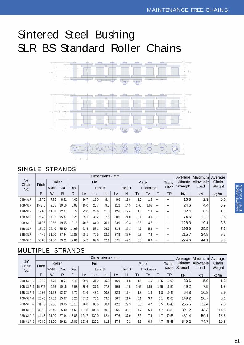
MA
INT
EN
AN
CE
FR
EE
C
HA
INS
51
Sintered Steel BushingSLR BS Standard Roller Chains
MAIN TEN AN CE FREE CH AIN S
S I N G L E S T R A N D S
S YC hain
No.Pitc h
0 8 B -S L R
1 0 B -S L R
1 2 B -S L R
1 6 B -S L R
2 0 B -S L R
2 4 B -S L R
2 8 B -S L R
3 2 B -S L R
P
16.8
24.6
32.4
74.6
128.3
195.6
215.7
274.6
2.9
4.4
6.3
12.2
19.1
25.5
34.8
44.1
0.6
0.9
1.1
2.6
3.8
7.3
9.3
9.9
R oller
Width Dia. Dia. Length Height Thic kness
Dimensions - mm
Pin Plate Trans .Pitc h
AverageUltimateS trength
MaximumAllowable
Load
AverageC hain
Weight
kN kN kg/m
12.70
15.875
19.05
25.40
31.75
38.10
44.45
50.80
W
7.75
9.65
11.68
17.02
19.56
25.40
31.00
31.00
R
8.51
10.16
12.07
15:87
19.05
25.40
27.94
29.21
D
4.45
5.08
5.72
8.26
10.16
14.63
15.88
17.81
LR
16.7
19.0
22.0
35.1
40.2
53.4
65.1
64.2
LC
18.0
20.7
23.6
38.2
44.0
58.1
70.5
69.6
L1
8.4
9.5
11.0
17.6
20.1
26.7
32.6
32.1
L2
9.6
11.2
12.6
20.5
23.9
31.4
37.9
37.5
H
11.8
14.5
17.4
21.0
29.3
35.1
37.0
42.2
T1
1.5
1.65
1.8
3.1
3.5
4.7
6.3
6.3
1.5
1.65
1.8
3.9
4.7
5.9
7.4
6.9
―
―
―
―
―
―
―
―
T2 T3 TP
―
―
―
―
―
―
―
―
M U L T I P L E S T R A N D S
S YC hain
No.Pitc h
0 8 B -S L R -2
1 0 B -S L R -2
1 2 B -S L R -2
1 6 B -S L R -2
2 0 B -S L R -2
2 4 B -S L R -2
2 8 B -S L R -2
3 2 B -S L R -2
P
33.6
49.2
64.8
149.2
256.6
391.2
431.4
549.2
5.0
7.5
10.8
20.7
32.4
43.3
59.1
74.7
1.3
1.8
2.9
5.1
7.3
14.5
18.5
19.8
R oller
Width Dia. Dia. Length Height Thic kness
Dimensions - mm
Pin Plate Trans .Pitc h
AverageUltimateS trength
MaximumAllowable
Load
AverageC hain
Weight
kN kN kg/m
12.70
15.875
19.05
25.40
31.75
38.10
44.45
50.80
W
7.75
9.65
11.68
17.02
19.56
25.40
31.00
31.00
R
8.51
10.16
12.07
15.87
19.05
25.40
27.94
29.21
D
4.45
5.08
5.72
8.26
10.16
14.63
15.88
17.81
LR
30.6
35.6
41.6
67.2
76.8
101.8
124.7
123.6
LC
31.9
37.3
43.1
70.1
80.6
106.5
130.0
129.2
L1
15.3
17.8
20.8
33.6
38.4
50.9
62.4
61.8
L2
16.6
19.5
22.3
36.5
42.2
55.6
67.6
67.4
H
11.8
14.5
17.4
21.0
29.3
35.1
37.0
42.2
T1
1.5
1.65
1.8
3.1
3.5
4.7
6.3
6.3
1.5
1.65
1.8
3.9
4.7
5.9
7.4
6.9
1.25
1.65
1.8
3.1
3.5
4.7
4.7
4.7
T2 T3 TP
13.92
16.59
19.46
31.88
36.45
48.36
59.56
58.55
H
P
W
T 2
T 2
L RR
L 1
L 2
L C
D
T 1
T 1
T 2
W
T 2L RL C
T 1
T 1
T 3
T 3
RD
TP
L 1
L 2
H
P
W
T 2
T 2
L RR
L 1
L 2
L C
D
T 1
T 1
T 2
W
T 2L RL C
T 1
T 1
T 3
T 3
RD
TP
L 1
L 2

MA
INT
EN
AN
CE
FR
EE
C
HA
INS
52
MAIN TEN AN CE FREE CH AIN S
Sintered Steel BushingSLR AN SI Standard Roller Chains (T.S)
M L T I P L E S T R A N D S
S YC hain
No.Pitc h
S Y 4 0 -S L R -2
S Y 5 0 -S L R -2
S Y 6 0 -S L R -2
S Y 8 0 -S L R -2
S Y 1 0 0 -S L R -2
S Y 1 2 0 -S L R -2
P
1.3
2.0
3.3
5.1
8.2
11.7
R oller
Width Dia. Dia. Length Height Thic kness
Dimensions - mm
Pin Plate Trans .Pitc h
AverageC hain
Weight
kg/m
6.17
10.7
14.7
25.0
38.4
51.7
MaximumAllowable
Load
kN
3.82
63.8
86.2
157
236
334
AverageUltimateS trength
kN
12.70
15.875
19.05
25.40
31.75
38.10
W
7.95
9.53
12.70
15.88
19.05
25.40
R
7.92
10.16
11.91
15.88
19.08
22.23
D
3.96
5.08
5.95
7.93
9.53
11.10
LR
33.1
40.5
52.3
65.2
78.6
99.1
LC
34.6
42.2
53.9
68.5
82.4
103.2
L1
16.6
20.3
26.2
32.6
39.3
49.6
L2
18
21.9
27.7
35.9
43.1
53.6
H
11.7
14.6
17.5
23.4
29.3
35.1
T1
1.5
2.0
2.4
3.2
4.0
4.8
T2
2.0
2.4
3.2
4.0
4.8
5.6
TP
15.6
19.2
24.9
31.1
37.6
48.0
S I N G L E S T R A N D S
S YC hain
No.Pitc h
S Y 4 0 -S L R
S Y 5 0 -S L R
S Y 6 0 -S L R
S Y 8 0 -S L R
S Y 1 0 0 -S L R
S Y 1 2 0 -S L R
P
0.7
1.1
1.7
2.7
4.3
6.0
R oller
Width Dia. Dia. Length Height Thic kness
Dimensions - mm
Pin Plate Trans .Pitc h
AverageC hain
Weight
kg/m
3.63
6.28
8.63
14.7
22.6
30.4
MaximumAllowable
Load
kN
19.1
31.9
43.1
78.5
118
167
AverageUltimateS trength
kN
12.70
15.875
19.05
25.40
31.75
38.10
W
7.95
9.53
12.70
15.88
19.05
25.40
R
7.92
10.16
11.91
15.88
19.08
22.23
D
3.96
5.08
5.95
7.93
9.53
11.10
LR
17.5
21.3
27.4
34.1
41.0
51.1
LC
19.0
23.0
29.0
37.4
44.8
55.2
L1
8.8
10.7
13.7
17.1
20.5
25.6
L2
10.2
12.3
15.3
20.3
24.3
29.6
H
11.7
14.6
17.5
23.4
29.3
35.1
T1
1.5
2.0
2.4
3.2
4.0
4.8
T2
2.0
2.4
3.2
4.0
4.8
5.6
TP
―
―
―
―
―
―
W
T 2
T 2
L R
T 1
L 1
L 2
L C
T 1
RD
T 2
W
T 2 L R
RD
L C
T 1
T 1
TP
H
P
L 1
L 2
W
T 2
T 2
L R
T 1
L 1
L 2
L C
T 1
RD
T 2
W
T 2 L R
RD
L C
T 1
T 1
TP
H
P
L 1
L 2

MA
INT
EN
AN
CE
FR
EE
C
HA
INS
S YC hain
No.Pitc h
S Y 4 0 -S L R -2
S Y 5 0 -S L R -2
S Y 6 0 -S L R -2
S Y 8 0 -S L R -2
S Y 1 0 0 -S L R -2
S Y 1 2 0 -S L R -2
P W R
12.70
15.875
19.05
25.40
31.75
38.10
7.95
9.53
12.70
15.88
19.05
25.40
7.92
10.16
11.91
15.88
19.08
22.23
3.96
5.08
5.95
7.93
9.53
11.10
31.1
39.1
49.3
62.2
75.4
95.4
32.7
40.7
50.9
65.5
79.1
99.6
15.6
19.6
24.7
31.1
37.7
47.7
17.1
21.1
26.2
34.4
41.4
51.9
11.7
14.6
17.5
23.4
29.3
35.1
1.5
2.0
2.4
3.2
4.0
4.8
14.4
18.1
22.8
29.3
35.8
45.4
31.4
51.0
54.6
127
200
314
6.3
10.6
15.1
25.7
39.3
53.2
1.1
1.9
2.8
4.9
7.6
11.1
R oller
Width Dia.
D
Dia.
Dimensions - mm
Pin Plate
Length Height Thic k.
Trans .Pitc h
AverageUltimateS trength
MaximumAllowable
Load
AverageC hain
Weight
LR LC L1 L2 H T TP kN kN kg/m
53
MAIN TEN AN CE FREE CH AIN S
Sintered Steel BushingSLR AN SI Standard Roller Chains (C.S)
M U L T I P L E S T R A N D S
S YC hain
No.Pitc h
S Y 4 0 -S L R
S Y 5 0 -S L R
S Y 6 0 -S L R
S Y 8 0 -S L R
S Y 1 0 0 -S L R
S Y 1 2 0 -S L R
P W R
12.70
15.875
19.05
25.40
31.75
38.10
7.95
9.53
12.70
15.88
19.05
25.40
7.92
10.16
11.91
15.88
19.08
22.23
3.96
5.08
5.95
7.93
9.53
11.10
16.5
20.5
25.9
33.0
39.8
49.8
18.1
22.3
27.5
35.9
43.1
53.2
8.3
10.3
13.0
16.5
19.9
24.9
9.8
12.0
14.5
19.4
23.2
28.3
11.7
14.6
17.5
23.4
29.3
35.1
1.5
2.0
2.4
3.2
4.0
4.8
―
―
―
―
―
―
15.7
25.5
37.3
63.7
100
157
3.62
6.27
8.63
14.7
22.5
30.4
0.6
1.0
1.5
2.5
3.9
5.8
R oller
Width Dia.
D
Dia.
Dimensions - mm
Pin Plate
Length Height Thic k.
Trans .Pitc h
AverageUltimateS trength
MaximumAllowable
Load
AverageC hain
Weight
LR LC L1 L2 H T TP kN kN kg/m
S I N G L E S T R A N D S
W
T
T
L R
L 1
L 2
L CR
D
T
W
T L R
R
L C TP
H
P
L 1
L 2
D
W
T
T
L R
L 1
L 2
L CR
D
T
W
T L R
R
L C TP
H
P
L 1
L 2
D

MA
INT
EN
AN
CE
FR
EE
C
HA
INS
S YC hain
No.Pitc h
C 2 0 4 0 -S L R
C 2 0 5 0 -S L R
C 2 0 6 0 H -S L R
C 2 0 8 0 H -S L R
C 2 1 0 0 H -S L R
P W R
25.40
31.75
38.10
50.80
63.50
7.95
9.53
12.70
15.88
19.05
7.92
10.16
11.91
15.88
19.05
3.96
5.08
5.95
7.93
9.53
16.5
20.5
29.1
35.8
42.7
18.5
22.5
31.5
39.0
46.6
8.3
10.3
14.6
17.9
21.4
10.2
12.2
16.9
21.1
25.2
11.5
15.1
17.2
22.8
28.8
1.5
2.0
3.2
4.0
4.8
15.7
25.5
37.3
63.7
100
2.65
4.31
6.28
10.7
17.1
0.5
0.8
1.4
2.4
3.5
R oller
Width Dia.
D
Dia.
Dimensions - mm
Pin Plate
Length Height Thic k.
AverageUltimateS trength
MaximumAllowable
Load
AverageC hain
Weight
LR LC L1 L2 H T kN kN kg/m
C O N V E Y O R S E R I E S (S T A N D A R D R O L L E R T Y P E )
S YC hain
No.Pitc h
C 2 0 4 2 -S L R
C 2 0 5 2 -S L R
C 2 0 6 2 H -S L R
C 2 0 8 2 H -S L R
C 2 1 0 2 H -S L R
P W R
25.40
31.75
38.10
50.80
63.50
7.95
9.53
12.70
15.88
19.05
7.92
10.16
11.91
15.88
19.05
3.96
5.08
5.95
7.93
9.53
16.5
20.5
29.1
35.8
42.7
18.5
22.5
31.5
39.0
46.6
8.3
10.3
14.6
17.9
21.4
10.2
12.2
16.9
21.1
25.2
11.5
15.1
17.2
22.8
28.8
1.5
2.0
3.2
4.0
4.8
31.4
51.0
74.6
127
200
4.50
7.30
10.6
18.1
29.0
1.0
1.6
2.8
4.6
6.9
R oller
Width Dia.
D
Dia.
Dimensions - mm
Pin Plate
Length Height Thic k.
AverageUltimateS trength
MaximumAllowable
Load
AverageC hain
Weight
LR LC L1 L2 H T kN kN kg/m
C O N V E Y O R S E R I E S (C A R R I E R R O L L E R T Y P E )
54
MAIN TEN AN CE FREE CH AIN S
Sintered Steel BushingSLR D ouble Pitch Roller Chains
W
P
T
T
L R
L 1
L 2
L CRD
H
W
T
T
L R
L 1
L 2
L CRD
P
H
W
P
T
T
L R
L 1
L 2
L CRD
H
W
T
T
L R
L 1
L 2
L CRD
P
H

MA
INT
EN
AN
CE
FR
EE
C
HA
INS
MAIN TEN AN CE FREE CH AIN S
Sintered Steel BushingH B-type H ollow Pin Chains
55
Sintered Steel BushingH R-type H ollow Pin Chains
S YC hain
No.Pitc h
H R 2 0 4 2 -S L
H R 2 0 5 2 -S L
H R 2 0 6 2 -S L
H R 2 0 8 2 -S L
P W R
25.40
31.75
38.10
50.80
7.95
9.53
12.70
15.88
15.88
19.05
22.23
28.58
5.63
7.09
8.29
11.34
4.03
5.13
6.04
8.08
16.7
20.1
26.0
32.4
17.6
21.5
27.2
34.3
8.4
10.1
13.0
16.2
9.2
11.2
14.2
18.1
12.0
15.0
18.1
24.1
1.5
2.0
2.4
3.2
12.7
19.6
28.4
51.0
1.77
3.14
4.22
7.65
0.8
1.3
1.8
3.2
R oller
Width Dia.
D d
Outs ide Ins ide
Dimensions - mm
Pin
Length Height Thic k.
PlateAverageUltimateS trength
MaximumAllowable
Load
AverageC hain
Weight
LR LC L1 L2 H T kN kN kg/m
H R -T Y P E H O L L O W P I N C H A I N S
S YC hain
No.Pitc h
H B 4 0 -S L
H B 5 0 -S L
H B 6 0 -S L
H B 8 0 -S L
H B 2 0 4 0 -S L
H B 2 0 5 0 -S L
H B 2 0 6 0 -S L
H B 2 0 8 0 -S L
P W R
12.70
15.875
19.05
25.40
25.40
31.75
38.10
50.80
7.95
9.53
12.70
15.88
7.95
9.53
12.70
15.88
7.92
10.16
11.91
15.88
7.92
10.16
11.91
15.88
5.63
7.09
8.29
11.34
5.63
7.09
8.29
11.34
4.03
5.13
6.04
8.08
4.03
5.13
6.04
8.08
16.7
20.1
26.0
32.4
16.7
20.1
26.0
32.4
17.6
21.5
27.2
34.3
17.6
21.5
27.2
34.3
8.4
10.1
13.0
16.2
8.4
10.1
13.0
16.2
9.2
11.2
14.2
18.1
9.2
11.2
14.2
18.1
12.0
15.0
18.1
24.1
12.0
15.0
18.1
24.1
1.5
2.0
2.4
3.2
1.5
2.0
2.4
3.2
12.7
19.6
28.4
51.0
12.7
19.6
28.4
51.0
1.77
3.14
4.22
7.65
1.77
3.14
4.22
7.65
0.6
1.0
1.5
2.5
0.5
0.8
1.1
2.0
R oller
Width Dia.
D d
Outs ide Ins ide
Dimensions - mm
Pin
Length Height Thic k.
PlateAverageUltimateS trength
MaximumAllowable
Load
AverageC hain
Weight
LR LC L1 L2 H T kN kN kg/m
H P -S S D O U B L E P I T C H
L 2
L 1
D RW
T
T
H
P
L C L R
d
L 2
L 1
D RW
T
T
H
P
L C L R
d
T
W
T
H
L 1
2L
D R
P
L RL C
d
T
W
T
H
L 1
2L
D R
P
L RL C
d
T
W
T
H
L 1
2L
D R
P
L RL C
d
T
W
T
H
L 1
2L
D R
P
L RL C
d

MA
INT
EN
AN
CE
FR
EE
C
HA
INS
The chain is designed to hold high quality lubricant between the pin and bushing with seals. Ex-panded applications are now possible from low to high speed, light to heavy load, and where lu-brication is not possible. This chain can drive for many hours without lubrication.Sales schedule will be in spring of 2004.
(Chain size)(Sprocket)(O ther applicable chains)(O perating temperature)(Range of speed)
(Selection and Caution)1) Standard Sprocket is used. N ote, however, the overall width of chain is slightly wider.
Take this into consideration for designing.2) W hen connecting the chain, make sure that all four (4) seals are installed.3) Lubricate connecting link with ample lubrication before assembly.4) W hen a lubrication leak is found (even at one location), replace that link immediately.5) The maximum chain elongation limit is 1.5% of the chain length.6) For use of chain in ambient temperature over 80℃, special lubrication for higher
temperature is available upon request.7) The covering plate of connecting link is a press-fit type with extra interferences.8) An offset link is not available.
#80 - #240 and 16B - 48BStandard sizeAttachment chains- 10℃ to + 60℃ (Special order up to max. 150℃)From slow speed 25m/min to high speed 150m/min
56
MAIN TEN AN CE FREE CH AIN S
Maintenance Free Roller Chains

MA
INT
EN
AN
CE
FR
EE
C
HA
INS
57
Maintenance Free Roller Chains
S YC hain
No.Pitc h
M F 1 6 A
M F 1 6 B
M F 2 0 A B
M F 2 4 A
M F 2 4 B
M F 2 8 A
M F 2 8 B
M F 3 2 A B
M F 4 0 A B
M F 4 8 A B
P W R
25.40
25.40
31.75
38.10
38.10
44.45
44.45
50.80
63.50
76.20
15.9
17.1
19.6
25.4
25.4
25.4
31.0
31.6
38.1
47.5
15.88
15.88
19.05
22.23
25.40
25.40
27.94
28.58
39.37
47.63
34.8
35.8
41.6
51.8
51.8
56.2
61.8
66.6
82.0
100.0
37.5
38.5
45.2
55.7
55.7
60.5
66.1
71.0
90.5
107.7
17.4
17.9
20.8
25.9
25.9
28.1
30.9
33.3
41.0
50.0
23.4
23.4
29.3
35.1
35.1
40.9
40.9
46.7
59.6
70.3
20.1
20.6
24.4
29.8
29.8
32.4
35.2
37.7
49.5
57.7
3.2
3.2
4.0
4.8
4.8
5.6
5.6
6.4
8.0
9.5
78.5
78.5
118
164
167
216
216
275
451
677
18.4
18.4
28.3
38.0
38.0
50.3
50.3
66.3
82.3
112.8
2.6
2.7
3.9
5.8
7.3
7.5
9.3
9.8
16.9
23.6
R oller
Width Dia.
LR
Dimensions - mm
Plate
Length Height Thic k
AverageUltimateS trength
MaximumAllowable
Load
AverageC hain
Weight
LC L1 L2 TH kN kN kg/m
MAIN TEN AN CE FREE CH AIN S
W
T
T
L 1
L 2
L C
R
H
P
L RW
T
T
L 1
L 2
L C
R
H
P
L R

LE
AF
CH
AIN
S
S YC hain
No.Lac ing
A L 4 2 2
A L 4 4 4
A L 4 6 6
A L 5 2 2
A L 5 4 4
A L 5 6 6
A L 6 2 2
A L 6 4 4
A L 6 6 6
A L 8 2 2
A L 8 4 4
A L 8 6 6
A L 1 0 2 2
A L 1 0 4 4
A L 1 0 6 6
A L 1 2 2 2
A L 1 2 4 4
A L 1 2 6 6
A L 1 4 2 2
A L 1 4 4 4
A L 1 4 6 6
A L 1 6 2 2
A L 1 6 4 4
A L 1 6 6 6
P D
2×2
4×4
6×6
2×2
4×4
6×6
2×2
4×4
6×6
2×2
4×4
6×6
2×2
4×4
6×6
2×2
4×4
6×6
2×2
4×4
6×6
2×2
4×4
6×6
12.70
15.875
19.05
25.40
31.75
38.10
44.45
50.80
3.96
5.08
5.95
7.93
9.53
11.10
12.70
14.28
8.4
14.6
21.2
10.5
19.0
27.6
12.4
22.2
32.6
16.6
29.4
43.0
19.6
36.2
53.5
24.0
43.7
63.4
27.8
51.2
73.6
31.8
58.4
84.8
10.3
12.7
15.2
20.2
24.5
29.2
34.2
40.3
1.5
2.0
2.4
3.2
4.0
4.8
5.6
6.4
4.03
5.15
6.04
8.00
9.59
11.22
12.82
14.47
18.6
37.3
55.9
30.4
60.8
94.1
43.1
86.3
129
72.6
145
218
108
216
324
152
304
456
205
410
615
269
539
809
1.86
3.43
3.92
3.04
5.30
6.28
4.41
7.45
8.73
7.35
13.2
15.4
11.6
20.6
24.0
16.5
29.1
34.2
22.1
38.9
46.1
28.3
49.9
58.8
0.36
0.70
1.04
0.58
1.16
1.73
0.81
1.68
2.46
1.42
2.88
4.23
2.46
4.81
7.24
3.35
6.58
9.82
4.99
9.56
14.13
6.35
12.62
18.87
Pitc h Dia.
Dimensions - mm
Pin Plate HoleDiaLength Height Thic kness
AverageUltimateS trength
MaximumAllowable
Load
AverageWeight
L H T S kN kN kg/m
Leaf ChainsSY Leaf chains are well suited for any application requiring flexible, high strength linkage for reciprocating motion or lift at relatively low speed. For their low cost and long life, widely used for lift trucks, masts and other lifting as construction and mining machines and excellent as balance and counterweights of machine tools and so forth.C O N ST R U C T I O N A N D L A C I N G CO MBIN ATIO N SBuilt of interlaced plates held together by riveted pins. The chain nomenclature indicates the lacing combinations.AL SERIES (LIG H T D U TY)Consisting of link plates of the same contour and thickness as the pin link plates of AN SI roller chains in same pitch. Mainly used for relatively constant, low, medium load with less shock.BL SERIES (H EAV Y D U TY)Consisting of link plates with next large size pitch chain of AN SI roller chains. Chiefly used for medium load with greater shock.LL SERIES (ISO 606)Consisting of link plates of the same contour and thickness as the pin link plates of BS roller chains
58
LEAF CH AIN S
2X2 2X3 3X4 4X4 4X6 6X6
T
H
D
P
S
2X2 2X3 3X4 4X4 4X6 6X6
T
H
D
P
S
L

LE
AF
CH
AIN
S
S YC hain
No.Lac ing
B L 4 2 2
B L 4 2 3
B L 4 3 4
B L 4 4 4
B L 4 4 6
B L 4 6 6
B L 5 2 2
B L 5 2 3
B L 5 3 4
B L 5 4 4
B L 5 4 6
B L 5 6 6
B L 6 2 2
B L 6 2 3
B L 6 3 4
B L 6 4 4
B L 6 4 6
B L 6 6 6
B L 8 2 2
B L 8 2 3
B L 8 3 4
B L 8 4 4
B L 8 4 6
B L 8 6 6
B L 1 0 2 2
B L 1 0 2 3
B L 1 0 3 4
B L 1 0 4 4
B L 1 0 4 6
B L 1 0 6 6
B L 1 2 2 2
B L 1 2 2 3
B L 1 2 3 4
B L 1 2 4 4
B L 1 2 4 6
B L 1 2 6 6
B L 1 4 2 2
B L 1 4 2 3
B L 1 4 3 4
B L 1 4 4 4
B L 1 4 4 6
B L 1 4 6 6
B L 1 6 2 2
B L 1 6 2 3
B L 1 6 3 4
B L 1 6 4 4
B L 1 6 4 6
B L 1 6 6 6
P D
2×2
2×3
3×4
4×4
4×6
6×6
2×2
2×3
3×4
4×4
4×6
6×6
2×2
2×3
3×4
4×4
4×6
6×6
2×2
2×3
3×4
4×4
4×6
6×6
2×2
2×3
3×4
4×4
4×6
6×6
2×2
2×3
3×4
4×4
4×6
6×6
2×2
2×3
3×4
4×4
4×6
6×6
2×2
2×3
3×4
4×4
4×6
6×6
12.70
15.875
19.05
25.40
31.75
38.10
44.45
50.80
5.08
5.95
7.93
9.53
11.10
12.70
14.28
17.45
10.5
12.5
16.8
19.0
23.0
27.5
12.4
15.0
20.0
22.2
27.6
32.4
16.6
19.5
26.2
29.2
36.5
43.0
19.6
23.8
32.5
36.2
45.0
53.5
24.0
28.6
38.7
43.7
53.4
63.4
27.8
34.2
45.5
51.2
62.6
73.6
31.8
38.8
51.7
58.4
71.2
84.8
35.8
43.7
58.9
65.9
80.2
96.2
11.7
14.6
17.5
24.1
29.3
35.1
40.9
46.7
2.0
2.4
3.2
4.0
4.8
5.6
6.4
7.2
5.15
6.04
8.00
9.59
11.20
12.82
14.39
17.62
27.5
27.5
40.7
54.4
54.4
82.5
42.7
42.7
64.0
85.3
85.3
127
70.6
70.6
106
141
141
212
114
114
172
228
228
342
157
157
245
314
314
471
207
207
332
414
414
621
270
270
405
539
539
810
392
392
618
785
785
1176
4.51
4.51
5.30
5.98
5.98
9.81
6.86
6.86
8.33
9.41
9.41
15.7
9.81
9.81
12.3
13.7
13.7
24.5
17.0
17.0
20.6
23.5
23.5
40.2
26.0
26.0
31.4
36.3
36.3
58.8
36.8
36.8
44.1
50.5
50.5
73.1
49.0
49.0
58.8
67.7
67.7
95.1
58.8
58.8
70.6
80.4
80.4
137.3
0.64
0.79
1.07
1.22
1.58
1.89
1.01
1.19
1.61
1.80
2.26
2.65
1.53
1.89
2.68
3.04
4.15
4.58
2.57
3.17
4.37
4.95
6.23
7.44
3.73
4.64
6.50
7.41
9.21
11.07
4.77
6.46
9.05
10.27
11.86
14.40
7.87
8.90
11.61
12.87
17.86
22.33
9.77
12.08
16.85
18.85
23.94
28.54
Pitc h Dia.
Dimensions - mm
Pin Plate HoleDiaLength Height Thic kness
AverageUltimateS trength
MaximumAllowable
Load
AverageWeight
L H T S kN kN kg/m
59
LEAF CH AIN S

LE
AF
CH
AIN
S
S YC hain
No.Lac ing
L L 0 8 2 2
L L 0 8 4 4
L L 0 8 6 6
L L 1 0 2 2
L L 1 0 4 4
L L 1 0 6 6
L L 1 2 2 2
L L 1 2 4 4
L L 1 2 6 6
L L 1 6 2 2
L L 1 6 4 4
L L 1 6 6 6
L L 2 0 2 2
L L 2 0 4 4
L L 2 0 6 6
L L 2 4 2 2
L L 2 4 4 4
L L 2 4 6 6
L L 2 8 2 2
L L 2 8 4 4
L L 2 8 6 6
L L 3 2 2 2
L L 3 2 4 4
L L 3 2 6 6
P D
2×2
4×4
6×6
2×2
4×4
6×6
2×2
4×4
6×6
2×2
4×4
6×6
2×2
4×4
6×6
2×2
4×4
6×6
2×2
4×4
6×6
2×2
4×4
6×6
12.70
15.875
19.05
25.40
31.75
38.10
44.45
50.80
4.45
5.08
5.72
8.28
10.19
14.63
15.90
17.81
7.6
13.0
18.4
9.3
16.1
22.9
10.7
18.5
26.3
50.1
30.2
43.2
20.1
35.1
50.1
28.4
49.4
70.4
34.0
60.0
86.0
35.0
61.0
87.0
10.9
13.7
16.1
21.0
26.4
33.4
37.0
42.2
1.25
1.65
1.80
3.20
3.50
4.90
6.3
6.3
4.46
5.09
5.73
8.30
10.21
14.65
15.92
17.83
17.8
31.1
44.5
22.2
44.5
66.7
28.9
57.8
86.7
58.0
116
174
95.0
190
285
170
340
510
200
400
600
260
520
780
0.31
0.60
0.89
0.48
0.94
1.40
0.63
1.22
1.82
1.48
2.90
4.31
2.17
4.24
6.30
4.02
7.79
11.55
5.42
10.56
15.71
5.92
11.50
17.06
Pitc h Dia.
Dimensions - mm
Pin Plate HoleDiaLength Height Thic kness
MinimumUltimateS trength
AverageC hain
Weight
L H T S kN kg/m
60
LEAF CH AIN S
Leaf Chains
2X2 2X3 3X4 4X4 4X6 6X6
T
H
D
P
S
2X2 2X3 3X4 4X4 4X6 6X6
T
H
D
P
S
L

LE
AF
CH
AIN
S
SELECTIO N O F LEAF CH AIN
D IMEN SIO N O F AN CH O R CLEV IS
C ONDIT ION OF US E
fS : S E R V IC E F A C T OR
C A L C UL A T ION OF T E NS IL E S T R E NG T H
DE T E R MINA T ION OF C HA IN S IZE
DE S IG N E ND C L E V IS
Chain speed [m/min.]N umber of working cycles in a day Max. chain load [kN ]
PD≦PB
PB[kN ]Tensile strength of chain chosen
PD=T・fS・fF
PD[kN ]Calculated tensile strength T[kN ]= Max. chain load
Lacing G =2(T max.+ 4C L + 0.008P )G =3(T max.+ 5C L + 0.008P )A=K +GK =3(T max.+ C L)G =K -(T max.+ 0.004P )A=K +GK =4(T max.+ C L)G =K -2(T max.+ 0.004P )A=K +GK =5(T max.+ C L)G =K -2(T max.+ 0.004P )A=K +GK =4(T max.+ C L)G =K -2(T max.- 0.004P )
P = chain pitch T max.= maximum link plate thickness R = end of radius =0.5P t = minimum thickness of outs ide flange= T max U= minimum depth of s lot for clearance= 0.5P C L= clearance = 0.038 for 15.875 pitch and smaller 0.051 for 19.05 pitch or larger
2×22×33×4
4×46×6 4×6
8×8
fF : S A F E T Y F A C T OR
T ype ofload
T ype ofload
C hainspeed
max.30m/min
No. of reciprocating
max./day
S moothload
S mooth starts & stopsand s low and gentle loadvariations .
F requent s tarts & stopsload variations and reverse motions .
S udden starts & stops , load variations and reverse motions .
S moothshocks
Heavyshocks
E xample of use
G E NE R AL C LE V IS P R OP OR T IONS
S uitableC hain s ize
fS
fF
1.0
1.3
1.5
AL seriesLL series
B L series
AL seriesLL seriesB L series
AL LL
B L
10100
912
91000
61
LEAF CH AIN S
12.5
K
R
U
At
G

ATTACH MEN T CH AIN S
STAN D ARD ATTACH MEN T
A-1attachment
AT
TA
CH
ME
NT
CH
AIN
S
62
K-1attachment
SA-1attachment SA-2
attachment
SK-1attachment
SK-2attachment
G K-1attachment
D -1attachment
D -3attachment
W A-2attachment
W SA-2attachment
D -1attachment
D -3attachment
A-2attachment
K-2attachment

ATTACH MEN T CH AIN S
SPECIAL ATTACH MEN T
63
AT
TA
CH
ME
NT
CH
AIN
S

AT
TA
CH
ME
NT
CH
AIN
S
S YC hain
No. Pitc h
0 8 B
1 0 B
1 2 B
1 6 B
2 0 B
P(B S )
0.61
0.89
1.14
2.59
3.76
R oller
Width Dia. Dia. Length Height Thic kness
Dimensions - mm
Pin Plate Trans .Pitc h
AverageC hain
Weight
kg/m
3.14
4.90
7.06
12.6
19.6
MaximumAllowable
Load
kN
17.8
22.3
28.9
60.8
95.1
MinimumUltimateS trength
kN
12.70
15.88
19.05
25.40
31.75
W
7.75
9.65
11.68
17.02
19.56
R
8.51
10.16
12.07
15.88
19.05
D
4.45
5.08
5.72
8.26
10.16
LR
16.7
19.0
22.0
35.1
40.2
LC
18.0
20.7
23.6
38.2
44.0
L1
8.4
9.5
11.0
17.6
20.1
L2
9.6
11.2
12.6
20.6
23.9
H
11.8
14.7
16.1
21.0
26.4
T1
1.5
1.65
1.8
3.2
3.5
T2
1.5
1.65
1.8
4.0
4.7
TP
13.92
16.59
19.46
31.88
36.45
64
ATTACH MEN T CH AIN S
BS Standard Attachment Chains
WSK attachment
L 1
L 2
D R
T
W
T
P
M d
CX
N
WSA attachment
L 1
L 2
D R
T
W
T
P
M d
CX
N
WA attachment WK attachment
L 1 D
L 2
R
T
W
T
JK
Md
D RL 1
2L
P
HS
T
W
T
N
P
HS
MdN
D-3 attachment
L 4
D
L 2
R
T
W
T
P
H
L 3
D-1 attachment
L 4
D
L 2
R
T
W
T
P
H
L 3D P PD
SK-1 attachment
T
W
T
XC
dM
Z
P
D RL
L 2
1
SA-1 attachment
L 1
L 2
D R
T
W
T
P
M d
CX
Z
A-1 attachment K-1 attachment
L 1 D
L 2
R
d M
T
W
T
JK
P
SH
Md
D RL 1
2L
P
HS
T
W
T
WSK attachment
L 1
L 2
D R
T
W
T
P
M d
CX
N
WSA attachment
L 1
L 2
D R
T
W
T
P
M d
CX
N
WA attachment WK attachment
L 1 D
L 2
R
T
W
T
JK
2K2J
Md
D RL 1
2L
P
HS
T
W
T
N
P
HS
MdN
D-3 attachment
L 4
D
L 2
R
T
W
T
P
H
L 3
D-1 attachment
L 4
D
L 2
R
T
W
T
P
H
L 3D P PD
SK-1 attachment
T
W
T
XC
dM
Z
P
D RL
L 2
1
SA-1 attachment
L 1
L 2
D R
T
W
T
P
M d
CX
Z
A-1 attachment K-1 attachment
L 1 D
L 2
R
d M
T
W
T
JK
P
SH
2K2J
Md
D RL 1
2L
P
HS
T
W
T
ZZ ZZ

AT
TA
CH
ME
NT
CH
AIN
S
A -1 , K -1 A T T A C H M E N T
S YC hain
No.
0 8 B
1 0 B
1 2 B
1 6 B
2 0 B
11.014.018.024.030.0
8.510.512.217.021.0
13.815.817.629.034.5
20.924.227.341.949.3
27.631.635.258.069.0
41.848.454.683.898.6
2.03.24.52025
4.06.49.04050
M Sd
C ommon Dimensions Original Dimensions
A-1 K -1 A-1 K -1
2K
Additional Weight
g/pcJ K 2J
W A -2 , W K -2 , W S A -2 , W S K -2 A T T A C H M E N T
S YC hain
No.
0 8 B
1 0 B
1 2 B
1 6 B
2 0 B
24.530.635.246.458.2
4.35.36.48.4
10.5
12.715.919.125.431.8
8.510.512.217.021.0
13.815.817.629.034.5
20.924.227.341.949.3
27.631.635.258.069.0
41.848.454.683.898.6
13.716.518.527.433.0
20.824.928.140.047.5
M N d
C ommon Dimensions Original Dimensions
WA WK WS A, WS KS
2K C XJ K 2J
S A -1 , S K -1 A T T A C H M E N T
S YC hain
No.
0 8 B
1 0 B
1 2 B
1 6 B
2 0 B
11.014.018.024.030.0
4.35.36.48.4
10.5
4.35.36.48.4
10.5
13.716.518.527.433.0
20.824.928.140.047.5
5.97.48.1
10.313.2
2.03.24.52025
4.06.49.04050
M C d
C ommon Dimensions
S A-1 S K -1X
Additional Weight
g/pcZ
D -1 , D -3 A T T A C H M E N T
S YC hain
No.
0 8 B
1 0 B
1 2 B
1 6 B
2 0 B
4.455.085.728.28
10.16
14.817.620.733.338.3
21.825.930.549.356.6
11.814.716.120.626.4
1.82.84.1
14.024.3
3.65.68.2
28.048.6
Dp L4 L3
C ommon Dimensions
D-1 D-3H
Additional Weight
g/pc
65
ATTACH MEN T CH AIN S

ATTACH MEN T CH AIN S
AN SI Standard Attachment Chains
66
B A S I C S P E C S F O R A S S E M B L I N G A T T A C H M E N T
S YC hain
No.(ANS I)
S Y 3 5
S Y 4 0
S Y 5 0
S Y 6 0
S Y 8 0
S Y 1 0 0
S Y 1 2 0
S Y 1 4 0
S Y 1 6 0
P RW
9.525
12.70
15.875
19.05
25.40
31.75
38.10
44.45
50.80
4.78
7.95
9.53
12.70
15.88
19.05
25.40
25.40
31.75
*5.08
7.92
10.16
11.91
15.88
19.05
22.23
25.4
28.58
3.58
3.96
5.08
5.95
7.93
9.53
11.10
12.70
14.28
5.9
8.2
10.3
12.7
16.2
19.6
24.7
26.9
32.1
6.8
9.1
11.6
13.9
18.8
23.2
28.5
31.2
36.4
9.0
11.7
14.6
17.5
23.4
29.3
35.1
40.9
46.7
1.25
1.5
2.0
2.4
3.2
4.0
4.8
5.6
6.4
10.8
19.1
31.9
43.1
78.5
118
167
216
275
0.34
0.60
0.98
1.46
2.52
3.91
5.76
7.41
9.79
Pitc h Dia. Width
Dimensions - mm
PinR oller Plate
Dia. Length Height Thic k.
AverageUltimateS trength
Average C hainWeight
D L1 L2 H T kN kg/m
WSK attachment
L 1
L 2
D R
T
W
T
P
M d
CX
N
WSA attachment
L 1
L 2
D R
T
W
T
P
M d
CX
N
WA attachment WK attachment
L 1 D
L 2
R
T
W
T
JK
Md
D RL 1
2L
P
HS
T
W
T
N
P
HS
MdN
D-3 attachment
L 4
D
L 2
R
T
W
T
P
H
L 3
D-1 attachment
L 4
D
L 2
R
T
W
T
P
H
L 3D P PD
SK-1 attachment
T
W
T
XC
dM
Z
P
D RL
L 2
1
SA-1 attachment
L 1
L 2
D R
T
W
T
P
M d
CX
Z
A-1 attachment K-1 attachment
L 1 D
L 2
R
d M
T
W
T
JK
P
SH
Md
D RL 1
2L
P
HS
T
W
T
WSK attachment
L 1
L 2
D R
T
W
T
P
M d
CX
N
WSA attachment
L 1
L 2
D R
T
W
T
P
M d
CX
N
WA attachment WK attachment
L 1 D
L 2
R
T
W
T
JK
2K2J
Md
D RL 1
2L
P
HS
T
W
T
N
P
HS
MdN
D-3 attachment
L 4
D
L 2
R
T
W
T
P
H
L 3
D-1 attachment
L 4
D
L 2
R
T
W
T
P
H
L 3D P PD
SK-1 attachment
T
W
T
XC
dM
Z
P
D RL
L 2
1
SA-1 attachment
L 1
L 2
D R
T
W
T
P
M d
CX
Z
A-1 attachment K-1 attachment
L 1 D
L 2
R
d M
T
W
T
JK
P
SH
2K2J
Md
D RL 1
2L
P
HS
T
W
T
ZZ ZZ
AT
TA
CH
ME
NT
CH
AIN
S

ATTACH MEN T CH AIN S
67
A -1 , K -1 A T T A C H M E N T
S YC hain
No.
S Y 3 5
S Y 4 0
S Y 5 0
S Y 6 0
S Y 8 0
S Y 1 0 0
S Y 1 2 0
S Y 1 4 0
S Y 1 6 0
7.99.5
12.715.919.125.428.634.738.1
6.47.9
10.311.915.919.823.028.631.8
4.55.87.38.7
11.714.617.520.423.3
9.512.715.919.125.431.838.144.550.8
14.317.323.328.135.944.354.763.271.9
19.125.431.838.150.863.676.289.0
101.6
28.634.646.656.271.888.6
109.4126.4143.8
0.91.2
46.51327476588
1.82.4
813265494
130176
M S d
C ommon Dimensions Original Dimensions
A-1 K -1 A-1 K -1Z
2K
Additional Weight
g/pcJ K 2J
W A -1 , W A -2 , W K -1 , W K -2 , W S A -1 , W S A -2 , W S K -1 , W S K -2 A T T A C H M E N T
S YC hain
No.
S Y 4 0
S Y 5 0
S Y 6 0
S Y 8 0
S Y 1 0 0
24.330.437.048.661.0
3.65.25.26.88.8
12.715.919.125.431.8
7.910.311.915.919.8
12.715.919.125.431.8
17.323.328.135.944.3
25.431.838.150.863.6
34.646.656.271.888.6
12.715.918.324.631.8
17.323.127.134.543.0
M N d
C ommon Dimensions Original Dimensions
WA WK WS A, WS KS
2K C XJ K 2J
S A -1 , S K -1 A T T A C H M E N T
S YC hain
No.
S Y 3 5
S Y 4 0
S Y 5 0
S Y 6 0
S Y 8 0
S Y 1 0 0
S Y 1 2 0
S Y 1 4 0
S Y 1 6 0
7.99.5
12.715.919.125.428.634.738.1
3.43.65.25.26.88.8
10.512.014.0
3.43.65.25.26.88.8
10.512.014.0
9.512.715.918.324.631.836.644.450.8
14.518.523.026.734.543.051.463.169.5
4.55.87.38.7
11.714.617.520.423.3
0.91.2
46.51327476588
1.82.4
813265494
130176
M C d
C ommon Dimensions
S A-1 S K -1X
Additional Weight
g/pcZ
D -1 , D -3 A T T A C H M E N T
S YC hain
No.
S Y 3 5
S Y 4 0
S Y 5 0
S Y 6 0
S Y 8 0
S Y 1 0 0
S Y 1 2 0
S Y 1 4 0
S Y 1 6 0
3.583.965.085.957.939.53
11.1012.7014.28
9.59.5
11.914.319.123.828.633.338.1
14.716.821.025.933.941.951.457.567.4
911.714.617.523.429.335.140.946.7
0.81237
12203045
1.6246
1424406090
Dp L4 L3
C ommon Dimensions
D-1 D-3H
Additional Weight
g/pc
AT
TA
CH
ME
NT
CH
AIN
S

ATTACH MEN T CH AIN S
D O U BLE PITCH ATTACH MEN T CH AIN S
68
B A S I C S P E C S F O R A S S E M B L I N G A T T A C H M E N T
S YC hain
No.(ANS I)
C 2 0 4 0
C 2 0 4 2
C 2 0 5 0
C 2 0 5 2
C 2 0 6 0 H
C 2 0 6 2 H
C 2 0 8 0 H
C 2 0 8 2 H
C 2 1 0 0 H
C 2 1 0 2 H
C 2 1 2 0 H
C 2 1 2 2 H
C 2 1 6 0 H
C 2 1 6 2 H
P RW
25.40
31.75
38.10
50.80
63.50
76.20
101.60
7.95
9.53
12.70
15.88
19.05
25.40
31.75
7.92
15.88
10.16
19.05
11.91
22.23
15.88
28.58
19.05
39.67
22.23
44.45
28.58
57.15
3.96
5.08
5.95
7.93
9.53
11.10
14.28
8.2
10.3
14.4
17.8
21.1
26.3
28.5
9.1
11.6
16.7
21.1
24.6
30.7
33.1
11.4
15.0
17.0
22.6
28.6
34.9
47.6
1.5
2.0
3.2
4.0
4.8
5.6
7.2
19.1
31.9
54.9
90.2
137
186
306
0.48
0.82
0.82
1.26
1.38
2.08
2.32
3.36
3.46
5.64
4.92
7.87
8.02
12.77
Pitc h Dia. Width
Dimensions - mm
PinR oller Plate
Dia. Length Height Thic k.
AverageUltimateS trength
Average C hainWeight
D L1 L2 H T kN kg/m
K
Md
J
P
T
S
ZZZ
M d
P
T
S
ZZZ
N
A-1 attachment A-2 attachment
T
W
T
2L
L 1
H
R RDJ
T
W
TK
L 2
D R RL 1
H
Md
2J
P
T
S
ZZZ
M d
P
T
S
ZZZ
N
K-1 attachment K-2 attachment
L 1
L 2
D R R
T
W
T
H
2J
T
W
TL
L
H
RR
2
1
Md
P
CX
M d
P
X
N1
1
2
2C
T T
SA-1 attachment SA-2 attachment
T
T
WRL 1 D
L 2
H
T
T
W
H
L
L 2
1 D R
Md
P
CX
M d
P
X
N1
1
2
2C
T T
SK-1 attachment SK-2 attachment
T
T
WRL 1 D
L 2
H
T
T
W
L 2
DL 1
H
R
d
P
GK-1 attachment
W
T
T
L 2
L 1 D R
H
P
D-1 attachment
L 3
L 4
D P
P
D-3 attachment
D P
W
T
T
L 2
D R
H
L 3
L 4
L 2
D R
T
W
T
H
K
Md
J
P
T
S
ZZZ
M d
P
T
S
ZZZ
N
A-1 attachment A-2 attachment
T
W
T
2L
L 1
H
R RDJ
T
W
TK
L 2
D R RL 1
H
K
Md
2J
P
T
S
ZZZ
M d
P
T
S
ZZZ
N
K-1 attachment K-2 attachment
L 1
L 2
D R R
T
W
T
H
2J
T
W
TL
L
H
RR
2
1
Md
P
CX
M d
P
X
N1
1
2
2C
T T
SA-1 attachment SA-2 attachment
T
T
WRL 1 D
L 2
H
T
T
W
H
L
L 2
1 D R
Md
P
CX
M d
P
X
N1
1
2
2C
T T
SK-1 attachment SK-2 attachment
T
T
WRL 1 D
L 2
H
T
T
W
L 2
DL 1
H
R
d
P
GK-1 attachment
W
T
T
L 2
L 1 D R
H
P
D-1 attachment
L 3
L 4
D P
P
D-3 attachment
D P
W
T
T
L 2
D R
H
L 3
L 4
L 2
D R
T
W
T
H
K
K
K
ZZ ZZ
AT
TA
CH
ME
NT
CH
AIN
S
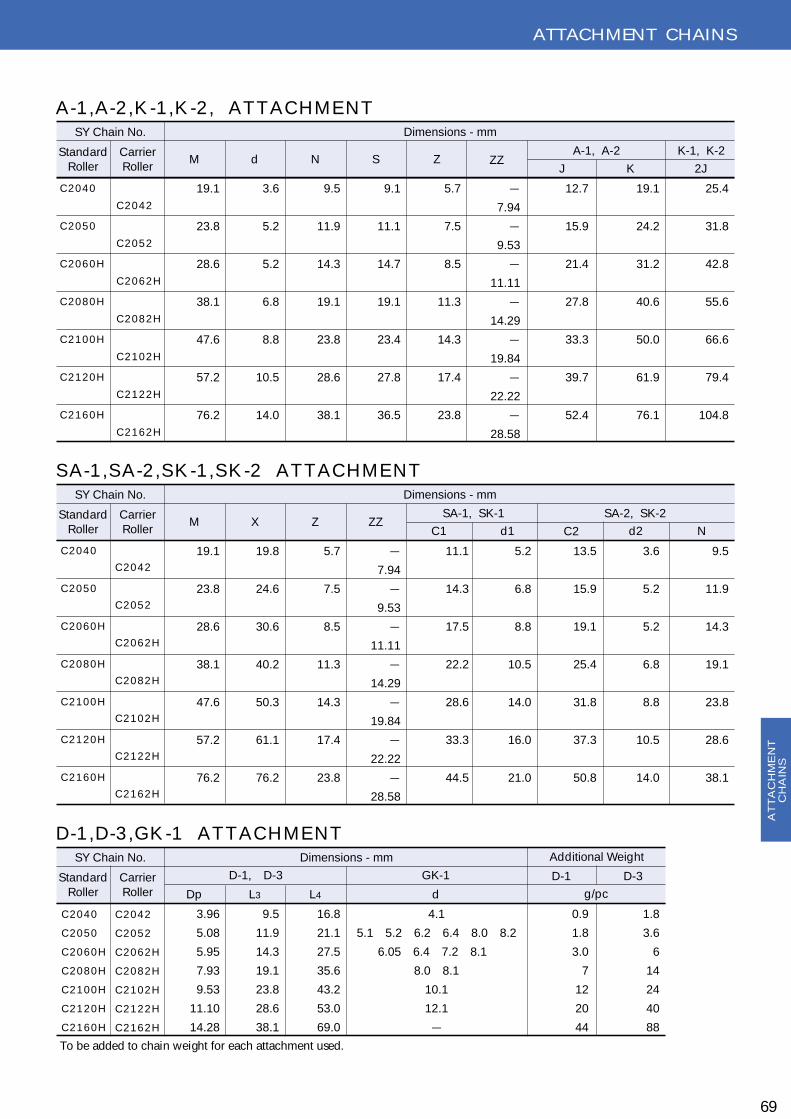
ATTACH MEN T CH AIN S
69
C 2 0 4 0
C 2 0 5 0
C 2 0 6 0 H
C 2 0 8 0 H
C 2 1 0 0 H
C 2 1 2 0 H
C 2 1 6 0 H
M N Sd
C 2 0 4 2
C 2 0 5 2
C 2 0 6 2 H
C 2 0 8 2 H
C 2 1 0 2 H
C 2 1 2 2 H
C 2 1 6 2 H
C 2 0 4 2
C 2 0 5 2
C 2 0 6 2 H
C 2 0 8 2 H
C 2 1 0 2 H
C 2 1 2 2 H
C 2 1 6 2 H
C 2 0 4 2
C 2 0 5 2
C 2 0 6 2 H
C 2 0 8 2 H
C 2 1 0 2 H
C 2 1 2 2 H
C 2 1 6 2 H
19.1
23.8
28.6
38.1
47.6
57.2
76.2
3.6
5.2
5.2
6.8
8.8
10.5
14.0
9.5
11.9
14.3
19.1
23.8
28.6
38.1
9.1
11.1
14.7
19.1
23.4
27.8
36.5
5.7
7.5
8.5
11.3
14.3
17.4
23.8
-
7.94
-
9.53
-
11.11
-
14.29
-
19.84
-
22.22
-
28.58
12.7
15.9
21.4
27.8
33.3
39.7
52.4
19.1
24.2
31.2
40.6
50.0
61.9
76.1
25.4
31.8
42.8
55.6
66.6
79.4
104.8
S tandardR oller
C arrierR oller
Dimensions - mmS Y C hain No.
A-1, A-2 K -1, K -2Z ZZ
J K 2J
A -1 , A -2 , K -1 , K -2 , A T T A C H M E N T
C 2 0 4 0
C 2 0 5 0
C 2 0 6 0 H
C 2 0 8 0 H
C 2 1 0 0 H
C 2 1 2 0 H
C 2 1 6 0 H
M Z ZZX
19.1
23.8
28.6
38.1
47.6
57.2
76.2
19.8
24.6
30.6
40.2
50.3
61.1
76.2
5.7
7.5
8.5
11.3
14.3
17.4
23.8
-
7.94
-
9.53
-
11.11
-
14.29
-
19.84
-
22.22
-
28.58
11.1
14.3
17.5
22.2
28.6
33.3
44.5
5.2
6.8
8.8
10.5
14.0
16.0
21.0
13.5
15.9
19.1
25.4
31.8
37.3
50.8
3.6
5.2
5.2
6.8
8.8
10.5
14.0
9.5
11.9
14.3
19.1
23.8
28.6
38.1
S tandardR oller
C arrierR oller
Dimensions - mmS Y C hain No.
S A-1, S K -1 S A-2, S K -2
C 2C 1 d1 d2 N
S A -1 , S A -2 , S K -1 , S K -2 A T T A C H M E N T
C 2 0 4 0
C 2 0 5 0
C 2 0 6 0 H
C 2 0 8 0 H
C 2 1 0 0 H
C 2 1 2 0 H
C 2 1 6 0 H
Dp
D-1, D-3 G K -1
L4 dL3
3.96
5.08
5.95
7.93
9.53
11.10
14.28
9.5
11.9
14.3
19.1
23.8
28.6
38.1
16.8
21.1
27.5
35.6
43.2
53.0
69.0
4.1
5.1 5.2 6.2 6.4 8.0 8.2
6.05 6.4 7.2 8.1
8.0 8.1
10.1
12.1
-
0.9
1.8
3.0
7
12
20
44
1.8
3.6
6
14
24
40
88
S tandardR oller
C arrierR oller
Dimensions - mmS Y C hain No.
D-1 D-3
Additional Weight
g/pc
D -1 , D -3 , G K -1 A T T A C H M E N T
To be added to chain weight for each attachment used.
AT
TA
CH
ME
NT
CH
AIN
S

ATTACH MEN T CH AIN S
SID E RO LLER CH AIN S
70
Average weight shows c hains with plastic s ide rollers every sec ond pitc hes on both s ides .
S YC hain
No.Pitc h
S Y -4 0
S Y -5 0
S Y -6 0
S Y -8 0
S Y -1 0 0
C 2 0 4 0
C 2 0 5 0
C 2 0 6 0 H
C 2 0 8 0 H
C 2 1 0 0 H
C 2 0 4 2
C 2 0 5 2
C 2 0 6 2 H
P
12.70
15.875
19.05
25.40
31.75
25.40
31.75
38.10
50.80
63.50
25.40
31.75
38.10
15.88
19.05
22.23
28.58
39.67
15.88
19.05
22.23
28.58
39.67
23.00
27.00
30.00
7.6
9.2
12.5
15.6
18.5
7.6
9.2
12.5
15.6
18.5
7.6
9.2
12.5
17.3
21.4
27.9
34.8
41.9
17.3
21.4
29.5
36.5
43.4
17.3
21.4
29.5
19.1
23.1
30.0
37.8
45.5
19.1
23.1
31.6
39.5
47.0
19.1
23.1
31.6
8.2
10.3
12.7
16.2
19.6
8.2
10.3
14.4
17.8
21.1
8.2
10.3
14.4
10.3
11.6
14.9
18.8
23.2
10.3
11.6
16.7
21.1
24.6
10.3
11.6
16.7
0.86
1.40
1.93
3.30
3.57
0.61
1.01
1.65
2.74
4.15
1.20
1.65
2.60
S ide roller C hain Pin
Dia. Width
Dimensions - mm
Pin-Length
AverageC hain
Weight
R S E S I1 I2 kg/m
R iveted S ide C otter S ide
L1 L2
SPECIAL AA-1 ATTACH MEN T CH AIN S
S YC hain
No. Pitc h
0 8 B
1 0 B
P M N
12.70
15.875
23.5
29.4
12.9
12.9
15.3
16.2
16.0
16.0
5.15
5.15
1.5
1.65
1.5
1.5
J S d
Dimensions - mm
Thic kness
Plate
T1 T2
T 2
P
T 1
T 1J
N
S
M
T 1
dT 2
P
T 1
T 1J
N
S
M
T 1
d
L C
L 1
L 2
I 1
I 2
E S
P
L 1
L 2
I 1
I 2
L CR S
AT
TA
CH
ME
NT
CH
AIN
S

ATTACH MEN T CH AIN S
TO P RO LLER CH AIN S
71
S YC hain
No.Pitc h
S Y -4 0
S Y -5 0
S Y -6 0
S Y -8 0
S Y -1 0 0
C 2 0 4 0
C 2 0 5 0
C 2 0 6 0 H
C 2 0 8 0 H
C 2 1 0 0 H
C 2 0 4 2
C 2 0 5 2
C 2 0 6 2 H
C 2 0 8 2 H
C 2 1 0 2 H
S Y -4 0
S Y -5 0
S Y -6 0
S Y -8 0
S Y -1 0 0
P W R
12.70
15.875
19.05
25.40
31.75
25.40
31.75
38.10
50.80
63.50
25.40
31.75
38.10
50.80
63.50
7.95
9.53
12.70
15.88
19.05
7.95
9.53
12.70
15.88
19.05
7.95
9.53
12.70
15.88
19.05
7.92
10.16
11.91
15.88
19.05
7.92
10.16
11.91
15.88
19.05
15.88
19.05
22.23
28.58
39.67
3.96
5.08
5.95
7.93
9.53
3.96
5.08
5.95
7.93
9.53
3.96
5.08
5.95
7.93
9.53
8.2
10.3
12.7
16.2
19.6
8.2
10.3
14.4
17.8
21.1
8.2
10.3
14.4
17.8
21.1
9.1
11.6
13.9
18.8
23.2
10.3
11.6
16.7
21.1
24.6
10.3
11.6
16.7
21.1
24.6
11.7
14.6
17.5
23.4
29.3
11.4
15.0
17.0
22.6
28.6
11.4
15.0
17.0
22.6
28.6
1.5
2.0
2.4
3.2
4.0
1.5
2.0
3.2
4.0
4.8
1.5
2.0
3.2
4.0
4.8
19.1
31.9
43.1
78.5
118
19.1
31.9
54.9
90.2
137
19.1
31.9
54.9
90.2
137
1.10
1.61
2.80
4.60
7.60
1.29
1.99
3.50
5.30
8.60
1.61
2.50
4.30
6.50
10.70
R oller
Width Dia. Dia.
D
Dia.
Dimensions - mm
T op R oller Dia. Only E very Link
Pin Plate
Length Height Thic kness
AverageUltimateS trength
AverageC hain
Weight
L1 L2 H T kN kg/m
12.7
15.9
18.3
24.6
31.8
15.0
19.0
23.0
29.0
35.4
15.0
19.0
23.0
29.0
35.4
15.88
19.05
22.23
28.58
39.67
15.88
19.05
22.23
28.58
39.67
15.88
19.05
22.23
28.58
39.67
11.00
15.00
18.00
24.00
30.00
Top-R oller
Pos ition
C R t
BO O K BIN D IN G CH AIN
S YC hain
No. Pitc h
4 0 B in din g C h a in
P X K
12.70 34.4 24.8 21.8 19.1 1.8
N
Dimensions - mmAverageUltimateS trength
AverageC hain
Weight
kN kg/m
P
K
X
N
P
K
X
N
LD R
P
HH
W
T
T
L 2
C
L C
D R
P
HH
W
T
T
R t
C
LL 1
LL 2
AT
TA
CH
ME
NT
CH
AIN
S
Average weight shows c hains with top rollers spac ed every sec ond. In c ase of large roller c hain, the sproc ket bec omes spec ial type of small out s ide diameter. (If c annot be use the sproc ket of double pitc h c hain.)

EN G IN EERIN G CH AIN S
81X SERIES
72
8 1 X R O O F T O P C H A I N
S YC hain
No.Pitc h
8 1 X R o o f
T o p C h a in
P W R
66.27 27.0 23.0 11.1 24.0 28.4 28.6 3.9 110 5.5
R oller
Width Dia. Dia.
D
R oofHeight
Dimensions - mm
Pin Plate
Length Height Thic k
AverageUltimateS trength
Approx.Weight
L1 L2 H T kN kg/m
63.5 31.8
R oofWidth
M HH
8 1 X . 8 1 X H . 8 1 X H -S
S YC hain
No.Pitc h
8 1 X
8 1 X H
8 1 X H -S
P W R
66.27
66.27
66.27
27.0
27.0
27.0
23.0
23.0
23.0
11.1
11.1
11.1
24.0
30.2
32.0
28.4
34.1
36.3
28.6
32.1
32.1
3.9
5.5
8.0
110
187
187
3.9
5.8
6.8
R oller
Width Dia. Dia.
D
Dimensions - mm
Pin Plate
Length Height Thic kness
AverageUltimateS trength
Approx.Weight
L1 L2 H T1 kN kg/m
3.9
8.0
8.0
T2
8 1 X P U S H E R
S YC hain
No.Pitc h
8 1 X P u s h e r
P W R
66.27 27.0 23.0 11.1 24.0 28.4 28.6 3.9 110
R oller
Width Dia. Dia.
D
Dimensions - mm
Pin Plate
Length Height Thic kness
AverageUltimateS trength
L1 L2 H T kN
65.1
A
L 1
L 2
D R
T
W
T
H
P
L 1
L 2
D R
T
W
T
H
P
A
T 1
T 1
2
2
L 1
L 2
D R
T
W
T
H
P
L 1
L 2
D R
T
W
T
H
P
A
T 1
T 1
2
2
L C
L 1
L 2
D
M
P
T
W
T
R
HH
H
L C
L 1
L 2
D
M
P
T
W
T
R
HH
H
PLAIN PUS HE R
R OOF TOP
EN
GIN
EE
RIN
GC
HA
INS

EN G IN EERIN G CH AIN S
73
3 9 3 9 G -4 A T T A C H M E N T
3 9 3 9 G -2 A T T A C H M E N T
S YC hain
No.Pitc h
3 9 3 9
P W R
203.20 27.0 23.0 11.1 24.0 28.4 28.6
38.1
38.1
38.1
110
R oller
Width Dia. Dia.
D
Dimensions - mm
Pin Plate G -4
Length Height Pitc h
AverageUltimateS trength
L1 L2 H
3.9
Thic k
T
7.2
Hole
dP1 kN
76.2
92.1
101.6
P2
S YC hain
No.Pitc h
3 9 3 9
P W R
203.20 27.0 23.0 11.1 24.0 28.4 28.6
38.1
76.2
92.1
101.6
110
R oller
Width Dia. Dia.
D
Dimensions - mm
Pin Plate G -2
Length Height Pitc h
AverageUltimateS trength
L1 L2 H
3.9
Thic k
T
7.2
Hole
dP1 kN
3939 ATTACH MEN T CH AIN
L 1
L 2
D RW
H
P
T
T
L 1
L 2
D RW
H
P
T
T
P 1
P 1
P 2
d
d
L 1
L 2
D RW
H
P
T
T
L 1
L 2
D RW
H
P
T
T
P 1
P 1
P 2
d
d
G-2
G-4
EN
GIN
EE
RIN
GC
HA
INS

TECH N ICAL IN FO RMATIO N
74
Trouble Shooting H intsThe below chart shows the most common chain failures and causes, but not necessarily the only ones.
Problem Poss ible C auses of Problem
・Overload・Inadequate lubric ation
・Properly lubric ation・R eplac e c hain when elongation exc eeds func tional limits
・Overload・Inadequate lubric ation
・R eplac e c hain as soon as poss ible
・Too little or too muc h s lac k・C hain obstruc tion・Loose c hain guard or bearing
・Adjust c enters or take-up・Inspec t & remove obstruc tion・Tighten bolts and c hec k bearings
・E xc ess ive c hain s lac k・C enter distanc e too long・stiff links
・Adjust c hain tens ioner・Install idler・Lubric ate or replac e c hain
・E xc ess ive load・Misalignment・Inadequate lubric ation・C orros in
・E xc ess ive c hain wear・E xc ess ive c hain s lac k・Inadequate lubric ation・S proc ket tooth wear
・R eplac e c hain with one of suitable strength・Inspec t alignment・C lean and establish c orrec t lubric ation・R eplac e with c orros ion res is tant c hain
・R eplac e c hain・Install tens ioner if nec essary・R eplac e sproc ket
・Misalignment ・R ealign sproc kets and shafts・R eplac e c hain and sproc kets if nec essary
S uggested R emedy
Pin or B ushing G alling
Turned Pins
E xc ess ive Noise
C hain Vibration
Wear on ins ide of linkplate and one s ide ofsproc ket teeth
C hain stiffens
C hain C limbs S proc kets
TE
CH
NIC
AL
INF
OR
MA
TIO
N
・E xtreme overload ・Inspec t the drive to determine the c ause of high load・R edes ign drive us ing a higher c apa- c ity c hain
Frac tured Plate

TECH N ICAL IN FO RMATIO N
75
Problem Poss ible C auses of Problem
・E xtreme overload ・Inspec t the drive to determine the c ause of high load・R edes ign drive us ing a higher c apa- c ity c hain
・Inspec t the drive to determine the c ause of high load・R edes ign drive us ing a higher c apa- c ity c hain
S uggested R emedy
B roken Pins
・Loading is greater than pins dynamic c apac ity
・Loading is greater than c hain's dynamic c apac ity
・S tress c orros ion c rac king
・Overload ・One-pitc h offsetlinks are not rec ommended・R edes ign drive us ing a higher c apa- c ity c hain
・Inspec t the drive to determine the c ause of high load・R edes ign drive us ing a higher c apa- c ity c hain
B roken Pins(c enter)
B roken Offset Link Pins
Fatigue Failure
C rac king
B roken R ollers
Worn Plates
・Protec t the c hain from c orros ion・Install anti-c orros ive c hains
・Foreign material between c hain and sproc ket tooth・Fatigue failure
・B ottom of plates worn due to rubbing on guides .
・R edes ign c hain speed and load・S hield drive from foreign matter
・C hain should be replac ed when wear bec ames over 5% of the plates height
TE
CH
NIC
AL
INF
OR
MA
TIO
N

TECH N ICAL IN FO RMATIO N
SELECTIO N O F RO LLER CH AIN
A T MOS P HE R IC C ONS IDE R A T ION
76
It is important to select the most suitable roller chains and sprockets for the job by careful study of power transmission re-quirements. The following basic factors should be considered when se-lecting roller chains for transmis-sion needs through there may be other factors.
The input power ratings appear-ing on the pages of 80 to 84, have been worked out under the following conditions.1) To be driven in normal atmos-
phere of -10 F゚ to 60 C゚free from ill effect of abrasive dust, corrosive gas, high hu-midity etc.
2) Sprockets should be aligned and mounted on parallel hori-zontal shafts.
3) Recommended method of lu-brication and recommended kind of lubricant should be used.
4) Should be driven at even load or small load variations.
Power rating of multiple strand chain is not simply calculable by multiplying the power rating of one strand by the number of strand because of uneven load distribution onto each strand. So, multiple strand factor should be used for expected service life. A service life of 15,000 hrs, can be expected when chain length is 100 pitches and the above conditions are met.
The following factors must be taken into consideration in selecting proper chain drive, depending on chain speed-normal or low speed. Also correction factors should be used, fully grasping the conditions of use.
a) D riven machine b) Type of load: smooth light or heavy shockc) Source of powerd) kW to be transmitted [kW 0:kW ]
e) RPM and diameter of high speed shaft[n1:rpm]f) RPM and diameter of low speed shaft[n2:rpm]g) Center distance of shaft [m]h) Chain-driving speed [S:m/min]
To obtain corrected power kW 1 multiply kW 0 by correct-ed factor f1 applied according to condition of use
S=Less than 50m/min.D ivided into two cases depend-ing on chain driving conditions1) For low speed drive with few
stops and starts, make the chain selection in a way to sat-isfy the following formula:T×f1×f3≦Max.allowable chain load.
2) For low speed drive with fre- quent stops and starts.
T×f1×f3×f4≦ Ave. ultimate strength. Select the chain by substituting the values of chain speed and max working load into formulas (1)& (2), after chain selected ten-tatively in the general way. N 1[-]=N umber of teeth on small sprocket. N 2[-]=N umber of teeth on large sprocket. P [mm]=Chain pitch S [m/min]=Chain speed =N 1・P・n1/1000 T [kN ]=Max. working load. =60×kW 0 / S
f2 : M U L T I -S T R A N D F A C T O R
P OINT IN S E L E C T ION R OL L E R C HA IN A ND S P R OC K E T
S E L E C T ION P R OC E DUR E A C C OR DING T O C HA IN S P E E D
IN CASE O F LO W SPEEDIN CASE O F N O RMAL SPEED
Number ofroller c hain strands f2
2 1.73 2.54 3.35 3.96 4.68 6.2
10 7.5
S=50~250m/min
D etermine low speed sprocket teeth N 2 from speed ratio R
See if each sprocket shaft diam-eter and mounting space satisfy specifications of machinery
O btain corrected pow-er kW 1 of single strand by referring to multiple strand factor f2
Economical sprockets for general in-dustrial use are recommended except when special sprockets are made due to unavoidable circumstances.
Makespecial sprocket
To obtain chain and high-speed sprocket teeth N 1 use roller chain quick selection chart and power rating chart according to RPM of high speed shaft and corrected power kW 1
kW 1=kW 0・f1
=kW 0・f1・f2
N 1
*Check
R=n1/n2
N 2=R・N 1
O K
Finally determined
TE
CH
NIC
AL
INF
OR
MA
TIO
N

TECH N ICAL IN FO RMATIO N
77
S YC hain
No.
Max.Allowable
Load
3 5
4 0
5 0
6 0
8 0
1 0 0
1 2 0
1 4 0
1 6 0
1 8 0
2 0 0
2 4 0
2.16
3.63
6.28
8.63
14.7
22.6
30.4
40.2
53.0
57.9
71.6
98.1
10.8
19.1
31.9
43.1
78.5
118
167
216
275
353
451
677
47.1
79.4
119
174
227
294
84.3
127
186
245
314
412
490
726
54.9
60.2
137
186
241
306
373
520
726
53.9
93.2
142
191
252
319
98.1
145
196
255
324
Ave.UltimateS trength
E ac h S eriesS Y S tandard(ANS I)
Ave.Ultimate S trength(kN)
E U H HE HU
C O N C I S E S E L E C T I O N D A T A
Driven LoadC ondition
Motor orTurbine
U n ifo r m S m o o t h
M o de r a t eS h o c k
H e a v yS h o c k
1.0
1.2
1.4
1.2
1.4
1.7
1.0
1.3
1.5
f1 : S E R V I C E F A C T O RInterval C ombustion E ngine
HydraulicDrive
C hain S peed
1 5 m /m in .
1 5~3 0
3 0~5 0
1.0
1.2
1.4
f3 : S P E E D C O E F F I C I E N T
f3 C hain S peed
2 5 m /m in .
2 5~5 0
7≦
8≦
f4 : S A F E T Y F A C T O R
f4
Mec hanic alDrive
Roller Chain Q uick Selection Chart
TE
CH
NIC
AL
INF
OR
MA
TIO
N
R E C OMME NDE D R ANG E S OF C HAIN C APAC ITIE S
R PM OF S MALL S PR OC K E T
0.5
0.5
0.5
0.10.05
10 50 100 500 1000
0.1
0.5
1
5
10
50
100
0.0510 50 100 500 1000
0.1
0.5
1
5
10
50
100
1
1
1
5
5
510
10
10
50
100
500
4 3 2 1500
100
100
50
50
SY
3 2 B-2
5
SY
2 8 B-2
5
SY
2 4 B-2
5
SY
2 0 B-2
5S
Y1 6 B
-25
SY
1 2 B-2
5
SY
1 0 B-2
5S
Y0 8 B
-25
SY
0 6 B-2
5
S Y2 0 0 -2
4
S Y1 8 0 -2
4
S Y1 6 0 -2
4
S Y1 4 0 -2
4
S Y1 2 0 -2
4
S Y1 0 0 -2
4
S Y1 0 0 -1
7
S Y8 0 -2
4
S Y8 0 -1
7
S Y6 0 -2
8
S Y6 0 -2
0
S Y5 0 -2
4
S Y5 0 -1
7
S Y4 0 -2
4
S Y4 0 -1
7
S Y3 5 -2
4
S Y3 5 -1
3
S Y2 5 -3
0
S Y2 5 -2
0
S Y2 4 0 -2
4
R PM OF S MALL S PR OC K E T
DE
SIG
N H
OR
SE
PO
WE
R(kw)
R E C OMME NDE D R ANG E S OF C HAIN C APAC ITIE SNUMB E R OF C HAIN S TR ANDS

TECH N ICAL IN FO RMATIO N
78
INS T A L L A T ION A NDA R R A NG E ME NT
C E NT E R DIS T A NC E A NDC HA IN L A P
To design excellent chain drives, chains and sprockets should be properly arranged and installed.
Chain lap on the small sprocket
must be at least 120 degrees.
T E NS ION A ND S L A C K
Proper amount of chain ten-sion should be maintained. Inad-equate tension will step up wear, while excessive sag will result in pulsating impact, stranding and breakage. Adequate slack is 4 % of the span for normal drives. In the following cases, the slack should be about 2 % of the span. 1) V ertical position or near to
vertical position.2) Center distance exceeding 1
meter.3) H eavy load application with
frequent starts and stops.4) Application with sudden re-
verse motions.
Sprockets can be spaced at any distance as long as their teeth do not touch. O ptimum distance is 30 to 50 times of pitch of the chain used except when there is a pulsating load. In case of pulsating drive, distance of less than 20 chain pitches is adequate.
A. G enerally roller chain slack is on
the lower side.
B. W hen the center distance is short
chain slack is adjusted by ex-
panding it.
C. W hen the center distance is long,
chain slack is adjusted by instal-
ling a tightner.
D . W hen chain slacks on the upper
side, adjust it by a tightner.
DR IV E P OS IT IONSHorizontal
Horizontal arrangements
E. Inclined operation should be
within 60 ,゚ possible.
F. Too much slack will cause chain
to ride up on the lower sprocket
or come off. It should be adjusted
by a tightner.
Inclined arrangements :
G , H
Excessive chain sag should be auto-
matically adjusted by a tightner. It is
mandatory when the driving
shaft(small sprocket) is placed on
the bottom side.
V ertical arrangements :
Inclined and V ertical
Center Distance
Lap
Center Distance
Lap
AD
AD
shaft adjusted
B
C
shaft adjusted
B
C
up to 60゚degreseE up to 60゚degreesE
F
E
F
E
G HG H
Over 60゚degrees
TE
CH
NIC
AL
INF
OR
MA
TIO
N

TECH N ICAL IN FO RMATIO N
79
Method AmountT y pe
A
B
C
S YC hain
No.
~S Y 5 0
S Y 6 0~S Y 8 0
S Y 1 0 0
S Y 1 2 0~
-10
|
0
0
|
40
40
|
50
50
|
60
-10
|
0
0
|
40
40
|
50
50
|
60
S AE 10
20
20
30
S AE 20
30
30
40
S AE 30
40
40
50
S AE 50
50
50
50
S AE 10
10
20
20
S AE 20
20
30
30
S AE 30
30
40
40
S AE 40
40
50
50
Lubric ation Type TYPE A・B TYPE C
L UB R IC A T ION
Proper lubrication of roller chains is a very important factor in getting their best possible per-formance and longer lifetime. N o matter how well a transmis-sion system is designed, if it is not properly lubricated, its serv-ice life will be shortened.Abrasion between the pin and bushing causes roller chains to stretch. Therefore, these parts should be well lubricated.The gap between the pin-link plate and roller-link plate on the slack side of the chain should be filled with lubricant.The oil forms a film which mini- mizes wear of the pin and bush-ing thus increasing the chain service life. It also reduces noises and cools down the chain running at high speed.
P OINT S OF L UB R IC A T ION
1) Fill and change oil periodi-cally.
2) G enerally, heavy oil and grease are not suitable as a lubricant.
3) Avoid mix of oil with another kind or other maker's.4) Adequate lubrication quantity is also essential for a chain's
longer service life.
●Periodic ally to keep c hain joints from drying
●Usually 4-20 drops of oil per mi-nute.
●E xc ess oil should be reserved in a s imple c ase.
●E ffec tive at medium and low speeds .
●To be dipped 6~12 mm.
●E ffec tive at rather high speeds .●To be dipped 12~25mm at
about 200m/min. c irc umferential speed of s linger disc .
●C ase should be c leaned to re-move impurities .
●E ffec tive for heavy load, high power and high speed.
●Ab 4 ltr/min. s hould be filled without oil s hortage or heating up.
●C los ed c irc ulating lubric ation s ys tem needs a c lean tank or c ase.
Lubrication by slinger discFor large speed ratio
Manual lubric ation
OIL
B R US H
Dripping lubric ation
OIL B ATH
Oil bath lubric ation
OIL LE VE L
Lubric ation by s linger discFor large speed ratio
OIL LE VE L
Lubric ation by s linger discFor small speed ratio
OIL LE VE L
Forc ed lubric ation
OIL B ATH
Temperature[ C゚]
TE
CH
NIC
AL
INF
OR
MA
TIO
N

W A R N I N GW A R N I N G
If misselected, misinstalled and missafe-guard Chain will break and serious injury or property damage can result.Please read an instruction manual carefully before installation.
R oller C hain A pplic ation InformationPlease select the chain (compare with Techni-cal D ata)when you use.If the chain abused through improper installa-tion , operating or maintenance procedures, failure can lead to personal injury or property damage.
Ultimate T ens ile S trengthU ltimate tensile strength is the one time pull required to break the chain therefore these are not the allowable working load.Safety factor must be considered when select-ing roller chain.A roller chain should never be loaded above 50% of U ltimate strength for even one cycle. W hen to use a multiple-strand roller chain, please consider the multiple-strand factor.
G uarding The chain can break in normal service due to the effects of wear ,fatigue or unexpected over-loads. Therefore a roller chain drive should have adequate guarding to prevent personal in-jury or property damage.
C onnec ting L ink W hen a slip-fit connecting link coverside for ease of assembly is used, a chain's working ca-pacity is reduced as much as 20% on some models. SU G IYAMA CH AIN offered N ew Con-necting Links with slip-fit coverside as strong as the base chain Recommend this N ew Con-necting Link to use.
Offs et L ink O ne-pitch offset links are very handy, pin andoffset linkplates have to be slip-fitted.It's allowable working load is approxi-mately 30% les s .Therefore one-pitch offset links are not recom-mended especially frequent, impact load mand high speed driving.The two-pitch offset link is combination of a roller link and an offset link connected with a riveted pin.So two-pitch offset link can be used in high speed or heavy duty applications.
C otter P in, S pring C lipKeep angle 90゜approx. to spread out prongs of cotter pin.D o not reuse the cotter and do not use the commercial cotters on the market.Be sure to insert spring clip properly into and seat in the groove on the end of Pin after instal-lation of Connecting Link cover plate onto pins, and do not spring one leg of the clip over the pin end to avoid breakdown of the leg.D o not spread out clip's legs too much to pre-vent falling spring clip off and unexpected ac-cident.Install spring clips with solid end pointing in the direction of chain travel.
R us t C orros ion If a chain is corroded, its capacity is reduced. If corrosion is severe, the link plates may crack even though the chain is not under load. In view this, carbon steel chain should not be exposed to corrosive conditions, acid fumes, salt spray sea water .Chain corrosion from normal atmospheric conditions may be minimized by proper lubri-cation.
80
!
TECH N ICAL IN FO RMATIO NT
EC
HN
ICA
LIN
FO
RM
AT
ION

Maintenanc e C hec k L is t
81
S proc ket Mis alignmentW ear on the sides of sprocket teeth generally indicates im-proper installation of sprockets and/or shafts. If shafts are out of parallel or not in the same plane, non-symmetrical wear will appear on sprockets or chain rollers.After proper alignment is made retighten set screws in sprock-et hubs.
C hain wear and E longationN ormal wear will cause some increase in chain length. H ow-ever,if a sudden increase in elongation elongation occurs , look for severe wear on the tips of sprocket teeth. This may be cased by any of the following : excessive loading or shock loading , displacement and/or wear in bearings,displacement of take-up ,or under-designed drives.Excessive elongation may be an indication that chain and/or sprockets should be replaced.Before replacing chain or sprockets ,recalculateinitial drive de-sign. Check chain tension if there is too much accumulated slack in the drive.
B roken C hain P artsG enerally caused by an overloaded drive ; extreme misalignment ; excessive elongation causing chain to jump sprocket teeth; heavy shock; improper drive design geometry; foreign objects.Recalculate initial drive design and make necessary correc-tion .Inspect sprockets and shafts for proper alignment or looseness.
L ink P late WearW ear on inside of the link plates and on one side of sprocket teeth may be caused by a misalignment misalignment of sprockets.Realign sprockets and shafts. Inspect chain carefully ,readjust chain properly or replace.
R emoving C hain Turn the drive until a connecting link is fully engaged with one of the sprockets so as to relieve the tension on the con-necting pin.The connecting link may then be removed.
E xc es s ive Nois eCan be caused by broken links and chain rollers,extreme mis-alignment, elongation, chain jumping sprocket teeth , loose sprockets, broken teeth ,accumulation of dirt packed into the chain or sprockets teeth, interference by foreign objects, con-tacting a fixed objectCheck for worn broken or missing parts. Check alignment of shafts and/or sprockets.
L ubric ationO n slow speed drives, where manual lubrication is used, if drip lubrication is used check for adequate oil flow and prop-er application to the chain. W ith bath or pump lubrication, check oil level and add oil if needed. Check oil for contaminationand change oil if needed.If pump lubrication is used, check each orifice to be sure if it is clear and is directing oil onto the chain properly.
R ec ommended R eplac ementMeasure the chain wear elongation and if elongation exceeds functional limits or is greater than 3% (0.36 inch in one foot) replace the entire chain. D o not connect a new section of chain to a worn chain be-cause it may run roughly and damage the drive. D o not con-tinue to run a chain worn beyond 3% elongation because the chain will not engage the sprock-ets properly and it may damage the sprockets.
C utting R iveted C hain The two pins of a pin link must be driven out of the link plate. Strike the pins alternately to avoid distortion of the roller link plates as well as the plates of the adjacent links.Chain cutting tools can also be used. Follow their instruction carefully.
Ins erting New L inksInsert only on new roller chain. Pitch variance between a new link and an old link,especially one which is elongated due to wear, will cause shock when the new link engages he sprock-ets.
Ins talling New C hainChain and/or related parts should be visually inspected for damage, which could have occurred during shipping prior to installation.N ever install new chain on worn sprockets as this will perma-nently damage chain. W ith new chain and sprockets installed
, check for proper and sprockets installed, check for proper tension and alignment.
1) Always lock out machinery power switch before attempting removal , installation, or any servic- ing of chain2) W ear eye and face protection when grinding, driving, or disassembling pins.3) Always wear gloves ,protective clothing and safety shoes with steel toe when working with chains.4) Make absolutely sure that chain is properly supported to prevent uncontrolled movement of chain and parts.5) Chain pressers and breaking tools are recommended to be in good working order and to be used according to instructions.6)Avoid plating or welding assembled chains or components.7) N ever repair damaged chains by replacing only the component parts.8) D amaged chain may be yielded and therefore should not be reworked.
Inspect on regularly scheduled basis for worn ,damaged or broken parts ,possible interfer-ence by other systems components, and prop-er lubrication.N ormal maintenance procedures can prevent most of the conditions described below. Carefully inspect roller chain drives on the same schedule as associated equipment.
CAU TIO NCAU TIO N
TECH N ICAL IN FO RMATIO N
TE
CH
NIC
AL
INF
OR
MA
TIO
N

82
TECH N ICAL IN FO RMATIO N
MA XIMUM K IL L OWA T T R A T ING OF 35
MA XIMUM K IL L OWA T T R A T ING OF 50
50No. ofTeethS malllS pkt.
No. ofTeethS malllS pkt.
No. ofTeethS malllS pkt.
Maximum R .P.M.-S mall S proc ket
Maximum R .P.M.-S mall S proc ket
Lubric ation S ystem
Lubric ation S ystem
Maximum R .P.M.-S mall S proc ket
Lubric ation S ystem
100
A
A B
A B
B
300 500 700 900 1200 1500 1800 2100 2500 3000 3500 4000 4500 5000 5500 6000
91 01 11 21 31 41 51 61 71 81 92 02 12 22 32 42 52 62 83 03 23 54 04 5
6500 7000
10 25 50 100 200 300 400 500 700 900 1000 1200 1400 1600 1800 2100 2400
91 01 11 21 31 41 51 61 71 81 92 02 12 22 32 42 52 62 83 03 23 54 04 5
2700 3000 3500
10 25 50 100 200 300 400 500 700 900 1000 1200 1400 1600 1800 2100 2400
91 01 11 21 31 41 51 61 71 81 92 02 12 22 32 42 52 62 83 03 23 54 04 5
2700 3000 3500
0.08 0.16 0.42 0.67 0.91 1.14 1.47 1.80 2.12 2.43 2.13 1.62 1.29 1.05 0.88 0.75 0.65 0.57 0.51 0.460.09 0.18 0.47 0.75 1.01 1.27 1.65 2.01 2.37 2.73 2.50 1.90 1.51 1.23 1.03 0.88 0.77 0.67 0.60 0.530.10 0.20 0.52 0.83 1.12 1.41 1.83 2.23 2.63 3.02 2.88 2.19 1.74 1.42 1.19 1.02 0.88 0.77 0.69 0.610.11 0.21 0.58 0.91 1.24 1.55 2.01 2.45 2.89 3.32 3.28 2.50 1.98 1.62 1.36 1.16 1.01 0.88 0.78 0.700.13 0.23 0.63 0.99 1.35 1.69 2.19 2.67 3.15 3.62 3.70 2.82 2.23 1.83 1.53 1.31 1.13 1.00 0.88 0.790.14 0.25 0.68 1.08 1.46 1.83 2.37 2.90 3.41 3.92 4.14 3.15 2.50 2.04 1.71 1.46 1.27 1.11 0.99 0.880.15 0.27 0.73 1.16 1.57 1.97 2.55 3.12 3.68 4.23 4.59 3.49 2.77 2.27 1.90 1.62 1.41 1.23 1.09 0.980.16 0.29 0.79 1.25 1.69 2.11 2.74 3.35 3.94 4.53 5.05 3.84 3.05 2.50 2.09 1.79 1.55 1.36 1.21 1.080.17 0.31 0.84 1.33 1.80 2.26 2.92 3.57 4.21 4.84 5.54 4.21 3.34 2.73 2.29 1.96 1.70 1.49 1.32 1.180.18 0.33 0.89 1.41 1.91 2.40 3.11 3.80 4.48 5.14 6.02 4.59 3.64 2.98 2.50 2.13 1.85 1.62 1.44 1.290.19 0.35 0.95 1.50 2.03 2.54 3.30 4.03 4.75 5.45 6.38 4.98 3.95 3.23 2.71 2.31 2.00 1.76 1.56 1.400.20 0.37 1.00 1.58 2.14 2.69 3.48 4.26 5.02 5.76 6.74 5.37 4.26 3.49 2.92 2.50 2.16 1.90 1.68 1.510.21 0.39 1.05 1.67 2.26 2.83 3.67 4.49 5.29 6.08 7.11 5.78 4.59 3.75 3.15 2.69 2.33 2.04 1.81 1.620.22 0.41 1.11 1.76 2.38 2.98 3.86 4.72 5.56 6.39 7.48 6.20 4.92 4.03 3.37 2.88 2.50 2.19 1.94 1.740.23 0.43 1.16 1.84 2.49 3.13 4.05 4.95 5.84 6.70 7.84 6.63 5.26 4.30 3.61 3.08 2.67 2.34 2.08 1.860.24 0.45 1.22 1.93 2.61 3.27 4.24 5.19 6.11 7.02 8.21 7.06 5.61 4.59 3.84 3.28 2.85 2.50 2.21 1.980.25 0.47 1.27 2.02 2.73 3.42 4.43 5.42 6.39 7.34 8.58 7.51 5.96 4.88 4.09 3.49 3.03 2.65 2.35 2.110.26 0.49 1.33 2.10 2.85 3.57 4.63 5.65 6.66 7.65 8.95 7.96 6.32 5.17 4.34 3.70 3.21 2.82 2.50 2.230.29 0.54 1.44 2.28 3.08 3.87 5.01 6.12 7.22 8.29 9.70 8.90 7.06 5.78 4.84 4.14 3.59 3.15 2.79 2.500.31 0.58 1.55 2.45 3.32 4.17 5.40 6.60 7.78 8.93 10.45 9.87 7.83 6.41 5.37 4.59 3.98 3.49 3.10 2.770.33 0.62 1.66 2.63 3.56 4.47 5.79 7.07 8.34 9.58 11.20 10.87 8.63 7.06 5.92 5.05 4.38 3.84 3.41 3.050.37 0.68 1.83 2.90 3.93 4.92 6.38 7.79 9.18 10.55 12.34 12.44 9.87 8.08 6.77 5.78 5.01 4.40 3.90 3.490.42 0.79 2.12 3.35 4.53 5.68 7.36 9.00 10.61 12.19 14.26 15.20 12.06 9.87 8.27 7.06 6.12 5.37 4.77 4.260.48 0.89 2.40 3.80 5.15 6.46 8.36 10.22 12.05 13.84 16.19 18.13 14.39 11.78 9.87 8.43 7.31 6.41 5.69 5.09
MA XIMUM K IL L OWA T T R A T ING OF 40
0.05 0.11 0.20 0.37 0.69 1.00 1.30 1.58 2.14 2.69 2.95 3.48 3.75 3.07 2.58 2.04 1.67 1.40 1.20 0.950.05 0.12 0.22 0.42 0.78 1.12 1.45 1.77 2.40 3.01 3.31 3.90 4.40 3.60 3.02 2.39 1.96 1.64 1.40 1.110.06 0.13 0.25 0.46 0.86 1.24 1.61 1.97 2.66 3.34 3.67 4.32 4.97 4.15 3.48 2.76 2.26 1.89 1.62 1.280.06 0.15 0.27 0.51 0.95 1.36 1.77 2.16 2.92 3.67 4.03 4.75 5.46 4.73 3.96 3.15 2.58 2.16 1.84 1.460.07 0.16 0.30 0.55 1.03 1.49 1.93 2.35 3.19 4.00 4.39 5.18 5.95 5.33 4.47 3.55 2.90 2.43 2.08 1.650.08 0.17 0.32 0.60 1.12 1.61 2.09 2.55 3.45 4.33 4.76 5.61 6.44 5.96 5.00 3.96 3.25 2.72 2.32 1.840.08 0.19 0.35 0.65 1.20 1.74 2.25 2.75 3.72 4.66 5.13 6.04 6.94 6.61 5.54 4.40 3.60 3.02 2.58 2.040.09 0.20 0.37 0.69 1.29 1.86 2.41 2.95 3.99 5.00 5.50 6.48 7.44 7.28 6.10 4.84 3.96 3.32 2.84 2.250.09 0.21 0.40 0.74 1.38 1.99 2.57 3.15 4.26 5.34 5.87 6.92 7.95 7.98 6.69 5.31 4.34 3.64 3.11 2.470.10 0.23 0.42 0.79 1.47 2.11 2.74 3.35 4.53 5.68 6.25 7.36 8.45 8.69 7.28 5.78 4.73 3.96 3.39 2.690.10 0.24 0.45 0.83 1.56 2.24 2.90 3.55 4.80 6.02 6.62 7.80 8.96 9.43 7.90 6.27 5.13 4.30 3.67 2.910.11 0.25 0.47 0.88 1.64 2.37 3.07 3.75 5.08 6.36 7.00 8.25 9.47 10.18 8.53 6.77 5.54 4.64 3.96 3.150.12 0.27 0.50 0.93 1.73 2.50 3.23 3.95 5.35 6.71 7.38 8.69 9.99 10.95 9.18 7.28 5.96 5.00 4.27 3.390.12 0.28 0.52 0.98 1.82 2.62 3.40 4.16 5.63 7.05 7.76 9.14 10.50 11.74 9.84 7.81 6.39 5.36 4.57 3.630.13 0.29 0.55 1.02 1.91 2.75 3.57 4.36 5.90 7.40 8.14 9.59 11.02 12.42 10.52 8.35 6.83 5.73 4.89 3.880.14 0.31 0.57 1.07 2.00 2.88 3.74 4.57 6.18 7.75 8.52 10.04 11.53 13.01 11.21 8.90 7.28 6.10 5.21 4.140.14 0.32 0.60 1.12 2.09 3.01 3.90 4.77 6.46 8.10 8.90 10.49 12.05 13.59 11.92 9.46 7.74 6.49 5.54 4.400.15 0.34 0.63 1.17 2.18 3.14 4.07 4.98 6.74 8.45 9.29 10.95 12.58 14.18 12.64 10.03 8.21 6.88 5.88 4.660.16 0.36 0.68 1.27 2.36 3.41 4.41 5.39 7.30 9.15 10.06 11.86 13.62 15.36 14.13 11.21 9.18 7.69 6.57 5.210.17 0.39 0.73 1.37 2.55 3.67 4.75 5.81 7.87 9.86 10.84 12.78 14.68 16.55 15.67 12.44 10.18 8.53 7.28 5.780.18 0.42 0.78 1.46 2.73 3.93 5.10 6.23 8.43 10.57 11.63 13.70 15.74 17.75 17.27 13.70 11.21 9.40 8.02 6.370.20 0.46 0.86 1.61 3.01 4.33 5.61 6.86 9.29 11.65 12.81 15.09 17.34 19.55 19.75 15.67 12.83 10.75 9.18 7.280.23 0.53 1.00 1.86 3.48 5.01 6.49 7.93 10.73 13.46 14.79 17.43 20.03 22.58 24.13 19.15 15.67 13.13 11.21 8.900.27 0.61 1.13 2.12 3.95 5.69 7.37 9.00 12.19 15.28 16.80 19.80 22.74 25.65 28.51 22.85 18.70 15.67 13.38 10.62
0.09 0.21 0.39 0.72 1.35 1.95 2.52 3.08 4.17 5.23 5.75 5.66 4.49 3.67 3.08 2.44 2.00 1.68 1.43 1.140.10 0.23 0.43 0.81 1.51 2.18 2.82 3.45 4.67 5.86 6.44 6.62 5.26 4.30 3.61 2.86 2.34 1.96 1.68 1.330.11 0.26 0.48 0.90 1.68 2.42 3.13 3.83 5.18 6.49 7.14 7.64 6.06 4.96 4.16 3.30 2.70 2.26 1.93 1.530.12 0.28 0.53 0.99 1.84 2.65 3.44 4.20 5.69 7.13 7.84 8.71 6.91 5.66 4.74 3.76 3.08 2.58 2.20 1.750.14 0.31 0.58 1.08 2.01 2.89 3.75 4.58 6.20 7.78 8.55 9.82 7.79 6.38 5.34 4.24 3.47 2.91 2.48 1.970.15 0.33 0.62 1.17 2.18 3.13 4.06 4.96 6.72 8.43 9.26 10.92 8.71 7.13 5.97 4.74 3.88 3.25 2.78 2.200.16 0.36 0.67 1.26 2.34 3.38 4.38 5.35 7.24 9.08 9.98 11.76 9.66 7.90 6.62 5.26 4.30 3.61 3.08 2.440.17 0.39 0.72 1.35 2.51 3.62 4.69 5.73 7.76 9.73 10.70 12.61 10.64 8.71 7.30 5.79 4.74 3.97 3.39 2.690.18 0.41 0.77 1.44 2.68 3.87 5.01 6.12 8.29 10.39 11.43 13.46 11.65 9.54 7.99 6.34 5.19 4.35 3.71 2.950.19 0.44 0.82 1.53 2.85 4.11 5.33 6.51 8.82 11.05 12.15 14.32 12.69 10.39 8.71 6.91 5.66 4.74 4.05 3.210.20 0.47 0.87 1.62 3.03 4.36 5.65 6.90 9.35 11.72 12.88 15.18 13.77 11.27 9.44 7.49 6.13 5.14 4.39 3.480.22 0.49 0.92 1.71 3.20 4.61 5.97 7.30 9.88 12.39 13.62 16.05 14.87 12.17 10.20 8.09 6.62 5.55 4.74 3.760.23 0.52 0.97 1.81 3.37 4.86 6.29 7.69 10.41 13.06 14.35 16.91 16.00 13.09 10.97 8.71 7.13 5.97 5.10 4.050.24 0.55 1.02 1.90 3.55 5.11 6.62 8.09 10.95 13.73 15.09 17.79 17.15 14.04 11.77 9.34 7.64 6.40 5.47 4.340.25 0.57 1.07 1.99 3.72 5.36 6.94 8.49 11.49 14.40 15.84 18.66 18.34 15.01 12.58 9.98 8.17 6.85 5.85 4.640.26 0.60 1.12 2.09 3.90 5.61 7.27 8.89 12.03 15.08 16.58 19.54 19.54 16.00 13.41 10.64 8.71 7.30 6.23 4.940.27 0.63 1.17 2.18 4.07 5.86 7.60 9.29 12.57 15.76 17.33 20.42 20.78 17.01 14.25 11.31 9.26 7.76 6.62 5.260.29 0.65 1.22 2.28 4.25 6.12 7.93 9.69 13.11 16.44 18.08 21.30 22.04 18.04 15.12 12.00 9.82 8.23 7.03 5.580.31 0.71 1.32 2.47 4.60 6.63 8.59 10.49 14.21 17.81 19.58 23.08 24.63 20.16 16.89 13.41 10.97 9.20 7.85 6.230.33 0.76 1.42 2.66 4.96 7.14 9.25 11.31 15.31 19.19 21.10 24.86 27.31 22.36 18.74 14.87 12.17 10.20 8.71 6.910.36 0.82 1.53 2.85 5.31 7.66 9.92 12.12 16.41 20.58 22.62 26.66 30.09 24.63 20.64 16.38 13.41 11.23 9.59 7.610.39 0.90 1.68 3.14 5.85 8.43 10.93 13.35 18.08 22.67 24.92 29.37 33.74 28.17 23.61 18.74 15.33 12.85 10.97 8.710.46 1.04 1.94 3.62 6.76 9.74 12.62 15.43 20.88 26.18 28.79 33.92 38.97 34.42 28.85 22.89 18.74 15.70 13.41 10.640.52 1.18 2.21 4.12 7.68 11.06 14.33 17.52 23.72 29.73 32.69 38.52 44.25 41.07 34.42 27.31 22.36 18.74 16.00 12.69
TE
CH
NIC
AL
INF
OR
MA
TIO
N

83
TECH N ICAL IN FO RMATIO N
0.17 0.39 0.72 1.35 1.95 2.52 3.63 4.71 5.75 6.78 7.79 8.78 9.77 8.60 7.46 6.54 5.19 4.25 3.56 3.040.19 0.44 0.81 1.51 2.18 2.83 4.07 5.27 6.45 7.60 8.73 9.84 10.94 10.07 8.73 7.66 6.08 4.98 4.17 3.560.21 0.48 0.90 1.68 2.42 3.13 4.51 5.85 7.15 8.42 9.68 10.91 12.13 11.62 10.07 8.84 7.02 5.74 4.81 4.110.23 0.53 0.99 1.84 2.66 3.44 4.96 6.42 7.85 9.25 10.63 11.99 13.33 13.24 11.48 10.07 7.99 6.54 5.48 4.680.25 0.58 1.08 2.01 2.90 3.75 5.41 7.00 8.56 10.09 11.59 13.07 14.53 14.93 12.94 11.36 9.01 7.38 6.18 5.280.27 0.63 1.17 2.18 3.14 4.07 5.86 7.59 9.27 10.93 12.55 14.16 15.74 16.69 14.47 12.70 10.07 8.25 6.91 5.900.30 0.67 1.26 2.35 3.38 4.38 6.31 8.17 9.99 11.77 13.52 15.25 16.96 18.51 16.04 14.08 11.17 9.15 7.66 6.540.32 0.72 1.35 2.52 3.62 4.70 6.76 8.76 10.71 12.62 14.50 16.35 18.18 19.99 17.67 15.51 12.31 10.07 8.44 7.210.34 0.77 1.44 2.69 3.87 5.01 7.22 9.36 11.44 13.48 15.48 17.46 19.41 21.34 19.36 16.99 13.48 11.03 9.25 7.900.36 0.82 1.53 2.86 4.12 5.33 7.68 9.95 12.17 14.33 16.47 18.57 20.65 22.70 21.09 18.51 14.69 12.02 10.07 8.600.38 0.87 1.62 3.03 4.36 5.65 8.14 10.55 12.90 15.20 17.46 19.69 21.89 24.07 22.87 20.07 15.93 13.04 10.93 9.330.40 0.92 1.72 3.20 4.61 5.98 8.61 11.15 13.63 16.06 18.45 20.81 23.14 25.44 24.70 21.68 17.20 14.08 11.80 10.070.42 0.97 1.81 3.38 4.86 6.30 9.07 11.75 14.37 16.93 19.45 21.94 24.39 26.81 26.58 23.32 18.51 15.15 12.70 10.840.45 1.02 1.90 3.55 5.11 6.62 9.54 12.36 15.11 17.80 20.45 23.07 25.64 28.20 28.50 25.01 19.85 16.24 13.61 11.620.47 1.07 2.00 3.72 5.36 6.95 10.01 12.97 15.85 18.68 21.46 24.20 26.91 29.58 30.46 26.73 21.21 17.36 14.55 12.420.49 1.12 2.09 3.90 5.62 7.28 10.48 13.58 16.60 19.56 22.47 25.34 28.17 30.97 32.47 28.50 22.61 18.51 15.51 13.240.51 1.17 2.18 4.08 5.87 7.60 10.95 14.19 17.35 20.44 23.48 26.48 29.44 32.37 34.52 30.30 24.04 19.68 16.49 14.080.54 1.22 2.28 4.25 6.12 7.93 11.43 14.80 18.10 21.32 24.50 27.63 30.72 33.77 36.61 32.13 25.50 20.87 17.49 14.930.58 1.32 2.47 4.61 6.63 8.59 12.38 16.04 19.60 23.10 26.54 29.93 33.27 36.58 39.86 35.91 28.50 23.32 19.55 16.690.62 1.42 2.66 4.96 7.15 9.26 13.34 17.28 21.12 24.89 28.59 32.24 35.85 39.41 42.94 39.82 31.60 25.87 21.68 18.510.67 1.53 2.85 5.32 7.66 9.93 14.30 18.53 22.65 26.68 30.66 34.57 38.44 42.26 46.04 43.87 34.82 28.50 23.88 20.390.74 1.68 3.14 5.86 8.44 10.94 15.75 20.41 24.95 29.40 33.77 38.08 42.34 46.55 50.72 50.18 39.82 32.60 27.32 23.320.85 1.94 3.63 6.77 9.75 12.63 18.20 23.57 28.82 33.96 39.01 43.99 48.91 53.78 58.59 61.31 48.66 39.82 33.37 28.500.97 2.21 4.12 7.69 11.07 14.35 20.67 26.77 32.73 38.56 44.30 49.96 55.55 61.07 66.54 71.96 58.06 47.52 39.82 34.00
MA XIMUM K IL L OWA T T R A T ING OF 60
MA XIMUM K IL L OWA T T R A T ING OF 80
MA XIMUM K IL L OWA T T R A T ING OF 100
1600 1800 200010 25 50 100 150 200 300 400 500 600 700 800 900 1000 1100 1200 1400
91 01 11 21 31 41 51 61 71 81 92 02 12 22 32 42 52 62 83 03 23 54 04 5
No. ofTeethS malllS pkt.
No. ofTeethS malllS pkt.
No. ofTeethS malllS pkt.
Maximum R .P.M.-S mall S proc ket
Lubric ation S ystem
Maximum R .P.M.-S mall S proc ket
Lubric ation S ystem
Maximum R .P.M.-S mall S proc ket
Lubric ation S ystem
A
A
B
B
A B C
10 25 50 100 150 200 300 400 500 600 700 800 900 1000 1100 1200 1400 1600
91 01 11 21 31 41 51 61 71 81 92 02 12 22 32 42 52 62 83 03 23 54 04 5
1800 2000
10 25 50 100 150 200 300 400 500 600 700 800 900 1000 1100 1200 1300 1400
91 01 11 21 31 41 51 61 71 81 92 02 12 22 32 42 52 62 83 03 23 54 04 5
1600 1800
0.40 0.91 1.69 3.16 4.55 5.89 8.48 10.99 13.44 15.83 18.19 15.13 12.68 10.83 9.39 8.24 6.54 5.35 4.48 3.830.45 1.02 1.90 3.54 5.09 6.60 9.51 12.32 15.06 17.74 20.38 17.72 14.85 12.68 10.99 9.65 7.66 6.27 5.25 4.480.49 1.13 2.10 3.92 5.65 7.32 10.54 13.65 16.69 19.66 22.59 20.45 17.14 14.63 12.68 11.13 8.83 7.23 6.06 5.170.54 1.24 2.31 4.31 6.20 8.04 11.58 15.00 18.33 21.60 24.82 23.30 19.53 16.67 14.45 12.68 10.06 8.24 6.90 5.890.59 1.35 2.52 4.70 6.76 8.76 12.62 16.35 19.99 23.55 27.06 26.27 22.02 18.80 16.29 14.30 11.35 9.29 7.78 6.650.64 1.46 2.73 5.09 7.33 9.49 13.67 17.71 21.65 25.51 29.31 29.36 24.60 21.01 18.21 15.98 12.68 10.38 8.70 7.430.69 1.57 2.94 5.48 7.89 10.23 14.73 19.08 23.33 27.49 31.58 32.56 27.29 23.30 20.19 17.72 14.06 11.51 9.65 8.240.74 1.69 3.15 5.88 8.46 10.96 15.79 20.46 25.01 29.47 33.86 35.87 30.06 25.67 22.25 19.53 15.49 12.68 10.63 9.070.79 1.80 3.36 6.27 9.04 11.71 16.86 21.85 26.70 31.47 36.15 39.28 32.92 28.11 24.37 21.38 16.97 13.89 11.64 9.940.84 1.92 3.58 6.67 9.61 12.45 17.94 23.24 28.40 33.47 38.45 42.80 35.87 30.63 26.55 23.30 18.49 15.13 12.68 10.830.89 2.03 3.79 7.07 10.19 13.20 19.01 24.63 30.11 35.48 40.76 45.97 38.90 33.21 28.79 25.27 20.05 16.41 13.75 11.740.94 2.15 4.01 7.48 10.77 13.95 20.10 26.04 31.83 37.50 43.08 48.59 42.01 35.87 31.09 27.29 21.65 17.72 14.85 12.680.99 2.26 4.22 7.88 11.35 14.71 21.18 27.45 33.55 39.53 45.42 51.21 45.20 38.59 33.45 29.36 23.30 19.07 15.98 13.641.04 2.38 4.44 8.29 11.94 15.47 22.28 28.86 35.28 41.57 47.76 48.47 41.38 35.87 31.48 24.98 20.45 17.14 14.631.09 2.50 4.66 8.70 12.52 16.23 23.37 30.28 37.01 43.61 50.10 56.50 51.81 44.24 38.34 33.65 26.70 21.86 18.32 15.641.15 2.61 4.88 9.10 13.11 16.99 24.47 31.70 38.75 45.66 52.46 59.16 55.23 47.15 40.87 35.87 28.47 23.30 19.53 16.671.20 2.73 5.10 9.51 13.70 17.76 25.57 33.13 40.50 47.72 61.83 58.71 50.13 43.45 38.14 30.26 24.77 20.76 17.721.25 2.85 5.32 9.93 14.30 18.52 26.68 34.57 42.25 49.79 57.20 64.50 62.27 53.17 46.08 40.45 32.10 26.27 22.02 18.801.35 3.09 5.76 10.75 15.49 20.07 28.90 37.45 45.77 53.94 61.96 69.88 69.59 59.42 51.50 45.20 35.87 29.36 24.60 21.011.46 3.33 6.21 11.59 16.69 21.62 31.14 40.34 49.32 58.11 66.76 75.28 77.18 65.90 57.12 50.13 39.78 32.56 27.29 23.301.56 3.57 6.66 12.42 17.89 23.18 33.39 43.25 52.88 62.30 71.58 80.72 85.03 72.60 62.93 55.23 43.82 35.87 30.06 25.671.72 3.93 7.33 13.68 19.71 25.54 36.78 47.65 58.25 68.64 78.85 88.92 97.26 83.04 71.98 63.17 50.13 41.03 34.39 29.361.99 4.54 8.47 15.81 22.77 29.50 42.49 55.04 67.28 79.28 91.08 102.71 114.20 101.5 87.94 77.18 61.25 50.13 42.01 35.872.26 5.16 9.62 17.95 25.86 33.50 48.25 62.51 76.41 90.04 103.44 116.65 129.7 121.1 104.9 92.09 73.08 59.82 50.13 42.80
0.76 1.74 3.24 6.05 8.71 11.28 16.25 21.05 25.73 27.85 22.10 18.09 15.16 12.94 11.22 9.85 8.73 7.81 6.40 5.360.85 1.95 3.63 6.77 9.76 12.64 18.21 23.59 28.84 32.62 25.89 21.19 17.76 15.16 13.14 11.53 10.23 9.15 7.49 6.280.95 2.16 4.02 7.51 10.82 14.01 20.18 26.15 31.96 37.63 29.86 24.44 20.49 17.49 15.16 13.31 11.80 10.56 8.64 7.241.04 2.37 4.42 8.25 11.88 15.39 22.17 28.72 35.11 41.37 34.03 27.85 23.34 19.93 17.27 15.16 13.45 12.03 9.85 8.251.13 2.58 4.82 8.99 12.95 16.78 24.17 31.32 38.28 45.11 38.37 31.40 26.32 22.47 19.48 17.09 15.16 13.57 11.10 9.311.23 2.80 5.22 9.74 14.03 18.18 26.19 33.93 41.47 48.87 42.88 35.10 29.41 25.11 21.77 19.10 16.94 15.16 12.41 10.401.32 3.01 5.62 10.50 15.12 19.59 28.21 36.55 44.68 52.65 47.56 38.92 32.62 27.85 24.14 21.19 18.79 16.81 13.76 11.531.42 3.23 6.03 11.25 16.21 21.00 30.25 39.19 47.91 56.45 52.39 42.88 35.94 30.68 26.60 23.34 20.70 18.52 15.16 12.711.51 3.45 6.44 12.02 17.31 22.42 32.30 41.84 51.15 60.27 57.38 46.96 39.36 33.60 29.13 25.56 22.67 20.29 16.60 13.911.61 3.67 6.85 12.78 18.41 23.85 34.35 44.51 54.40 64.11 62.51 51.17 42.88 36.61 31.73 27.85 24.70 22.10 18.09 15.161.71 3.89 7.26 13.55 19.52 25.28 36.42 47.18 57.68 67.96 67.80 55.49 46.50 39.71 34.42 30.20 26.79 23.97 19.62 16.441.80 4.11 7.67 14.32 20.63 26.72 38.49 49.87 60.96 71.83 73.22 59.93 50.22 42.88 37.17 32.62 28.93 25.89 21.19 17.761.90 4.34 8.09 15.10 21.74 28.17 40.58 52.57 64.26 75.72 78.78 64.48 54.04 46.14 39.99 35.10 31.13 27.85 22.80 19.102.00 4.56 8.51 15.87 22.86 29.62 42.67 55.28 67.57 79.62 84.47 69.14 57.94 49.47 42.88 37.63 33.38 29.86 24.44 20.492.10 4.78 8.93 16.65 23.99 31.08 44.77 57.99 70.89 83.54 90.29 73.90 61.94 52.88 45.84 40.23 35.68 31.92 26.13 21.902.20 5.01 9.34 17.44 25.12 32.54 46.87 60.72 74.23 87.46 96.25 78.78 66.02 56.37 48.86 42.88 38.03 34.03 27.85 23.342.29 5.23 9.77 18.22 26.25 34.01 48.98 63.46 77.57 91.41 102.32 83.75 70.19 59.93 51.94 45.59 40.43 36.18 29.61 24.822.39 5.46 10.19 19.01 27.39 35.48 51.10 66.21 80.93 95.36 108.52 88.83 74.44 63.56 55.09 48.35 42.88 38.37 31.40 26.322.59 5.91 11.04 20.60 29.67 38.44 55.36 71.72 87.67 103.31 118.68 99.27 83.19 71.03 61.57 54.04 47.92 42.88 35.10 29.412.79 6.37 11.89 22.19 31.96 41.41 59.64 77.27 94.46 111.30 127.9 110.1 92.26 78.78 68.28 59.93 53.15 47.56 38.92 32.623.00 6.83 12.75 23.79 34.27 44.40 63.95 82.85 101.28 119.33 137.1 121.3 101.6 86.78 75.22 66.02 58.55 52.39 42.88 35.943.30 7.53 14.05 26.21 37.75 48.91 70.45 91.27 111.57 131.5 151.0 138.7 116.3 99.27 86.05 75.52 66.97 59.93 49.05 41.113.81 8.69 16.22 30.28 43.61 56.50 81.38 105.43 128.9 151.9 174.5 169.5 142.1 121.3 105.1 92.26 81.83 73.22 59.93 50.224.33 9.87 18.43 34.38 49.52 64.16 92.42 119.73 146.4 172.5 198.1 202.3 169.5 144.7 125.4 110.1 97.64 87.37 71.51 59.93
TE
CH
NIC
AL
INF
OR
MA
TIO
N

84
TECH N ICAL IN FO RMATIO N
TE
CH
NIC
AL
INF
OR
MA
TIO
N
MA XIMUM K IL L OWA T T R A T ING OF 120
MA XIMUM K IL L OWA T T R A T ING OF 140
MA XIMUM K IL L OWA T T R A T ING OF 160
No. ofTeethS malllS pkt.
No. ofTeethS malllS pkt.
No. ofTeethS malllS pkt.
Maximum R .P.M.-S mall S proc ket
Lubric ation S ystem
Maximum R .P.M.-S mall S proc ket
Lubric ation S ystem
Maximum R .P.M.-S mall S proc ket
Lubric ation S ystem
A
A
A B C
B C
B C
10 25 50 100 150 200 300 400 500 600 700 800 900 1000 1100 1200 1300 1400
91 01 11 21 31 41 51 61 71 81 92 02 12 22 32 42 52 62 83 03 23 54 04 5
10 25 50 100 150 200 250 300 350 400 450 500 550 600 700 800 900 1000
91 01 11 21 31 41 51 61 71 81 92 02 12 22 32 42 52 62 83 03 23 54 04 5
10 25 50 100 150 200 250 300 350 400 450 500 550 600 650 700 750 800
91011121314151617181920212223242526283032354045
1.29 2.93 5.47 10.21 14.71 19.05 27.44 35.55 42.36 32.23 25.57 20.93 17.54 14.98 12.98 11.39 10.10 9.04 8.15 7.401.44 3.29 6.13 11.44 16.48 21.35 30.75 39.83 48.69 37.74 29.95 24.51 20.54 17.54 15.20 13.34 11.83 10.59 9.55 8.671.60 3.64 6.79 12.68 18.26 23.66 34.08 44.15 53.97 43.54 34.55 28.28 23.70 20.24 17.54 15.39 13.65 12.22 11.02 10.001.75 4.00 7.46 13.93 20.06 25.99 37.44 48.50 59.29 49.61 39.37 32.23 27.01 23.06 19.99 17.54 15.56 13.92 12.55 11.391.91 4.36 8.14 15.19 21.87 28.34 40.82 52.88 64.64 55.94 44.39 36.34 30.45 26.00 22.54 19.78 17.54 15.70 14.15 12.852.07 4.72 8.82 16.45 23.70 30.70 44.22 57.29 70.03 62.52 49.61 40.61 34.03 29.06 25.19 22.10 19.60 17.54 15.82 14.362.23 5.09 9.50 17.72 25.53 33.08 47.64 61.72 75.45 69.34 55.02 45.04 37.74 32.23 27.93 24.51 21.74 19.45 17.54 15.922.39 5.46 10.18 19.00 27.37 35.46 51.08 66.18 80.90 76.39 60.62 49.61 41.58 35.50 30.77 27.01 23.95 21.43 19.32 17.542.55 5.83 10.87 20.29 29.23 37.86 54.54 70.65 86.37 83.66 66.39 54.34 45.54 38.88 33.70 29.58 26.23 23.47 21.16 19.212.72 6.20 11.57 21.58 31.09 40.27 58.01 75.15 91.87 91.15 72.33 59.20 49.61 42.36 36.72 32.23 28.58 25.57 23.06 20.932.88 6.57 12.26 22.88 32.96 42.70 61.50 79.67 97.39 98.85 78.44 64.20 53.81 45.94 39.82 34.95 30.99 27.73 25.01 22.703.04 6.94 12.96 24.18 34.83 45.13 65.00 84.21 102.94 106.75 84.71 69.34 58.11 49.61 43.00 37.74 33.47 29.95 27.01 24.513.21 7.32 13.66 25.49 36.72 47.57 68.52 88.77 108.51 114.86 91.15 74.60 62.52 53.38 46.27 40.61 36.01 32.23 29.06 26.383.37 7.70 14.36 26.81 38.61 50.02 72.05 93.34 114.10 123.16 97.73 79.99 67.04 57.24 49.61 43.54 38.62 34.55 31.16 28.283.54 8.08 15.07 28.12 40.51 52.48 75.59 97.93 119.71 131.65 104.47 85.51 71.66 61.19 53.04 46.55 41.28 36.94 33.31 30.233.71 8.46 15.78 29.45 42.41 54.95 79.15 102.54 125.34 140.33 111.36 91.15 76.39 65.22 56.53 49.61 44.00 39.37 35.50 32.233.87 8.84 16.49 30.77 44.33 57.43 82.72 107.16 130.99 149.19 118.39 96.90 81.21 69.34 60.10 52.75 46.78 41.86 37.74 34.264.04 9.22 17.20 32.11 46.24 59.91 86.29 111.80 136.66 158.23 125.57 102.77 86.13 73.54 63.74 55.94 49.61 44.39 40.03 36.344.38 9.99 18.64 34.78 50.10 64.90 93.49 121.11 148.05 174.45 140.33 114.86 96.26 82.19 71.24 62.52 55.45 49.61 44.74 40.614.72 10.76 20.08 37.47 53.97 69.92 100.72 130.48 159.50 187.94 155.63 127.38 106.75 91.15 79.00 69.34 61.49 55.02 49.61 45.045.06 11.54 21.53 40.18 57.87 74.97 107.99 139.90 171.02 201.51 171.45 140.33 117.60 100.41 87.04 76.39 67.74 60.62 54.66 49.615.57 12.71 23.72 44.26 63.75 82.59 118.96 154.12 188.40 221.99 196.12 160.52 134.52 114.86 99.56 87.38 77.49 69.34 62.52 56.756.44 14.68 27.40 51.12 73.64 95.40 137.42 178.03 217.62 256.43 239.61 196.12 164.36 140.33 121.64 106.75 94.68 84.71 76.39 69.347.31 16.67 31.11 58.06 83.63 108.34 156.06 202.17 247.14 291.21 285.91 234.02 196.12 167.45 145.14 127.38 112.97 101.09 91.15 82.74
1500 1600
1.99 4.54 8.46 15.80 22.75 29.48 36.03 42.46 48.78 55.00 56.13 47.92 41.54 36.45 28.93 23.68 19.84 16.94 14.69 12.892.23 5.08 9.48 17.70 25.49 33.03 40.37 47.57 54.65 61.63 65.74 56.13 48.65 42.70 33.88 27.73 23.24 19.84 17.20 15.102.47 5.63 10.51 19.62 28.26 36.61 44.75 52.73 60.58 68.32 75.84 64.75 56.13 49.26 39.09 31.99 26.81 22.89 19.84 17.422.71 6.19 11.55 21.55 31.04 40.22 49.16 57.93 66.55 75.05 83.44 73.78 63.95 56.13 44.54 36.45 30.55 26.08 22.61 19.842.96 6.75 12.59 23.50 33.85 43.85 53.60 63.16 72.56 81.82 90.97 83.19 72.11 63.29 50.22 41.11 34.45 29.41 25.49 22.373.20 7.31 13.64 25.46 36.67 47.50 58.07 68.42 78.60 88.64 98.55 92.97 80.59 70.73 56.13 45.94 38.50 32.87 28.49 25.013.45 7.88 14.70 27.42 39.50 51.18 62.56 73.71 84.68 95.50 106.18 103.11 89.37 78.44 62.25 50.95 42.70 36.45 31.60 27.733.70 8.44 15.76 29.40 42.35 54.87 67.07 79.04 90.80 102.39 113.84 113.59 98.46 86.41 68.57 56.13 47.04 40.16 34.81 30.553.95 9.02 16.82 31.39 45.22 58.58 71.61 84.38 96.94 109.32 121.54 124.40 107.83 94.64 75.10 61.47 51.51 43.98 38.12 33.464.20 9.59 17.89 33.39 48.10 62.31 76.17 89.76 103.11 116.28 129.28 135.54 117.49 103.11 81.82 66.97 56.13 47.92 41.54 36.454.46 10.17 18.97 35.40 50.99 66.06 80.75 95.15 109.31 123.27 137.06 146.99 127.41 111.82 88.74 72.63 60.87 51.97 45.05 39.534.71 10.75 20.05 37.42 53.90 69.82 85.35 100.57 115.54 130.29 144.87 158.75 137.60 120.76 95.83 78.44 65.74 56.13 48.65 42.704.97 11.33 21.14 39.44 56.81 73.60 89.97 106.01 121.79 137.34 152.70 167.89 148.05 129.93 103.11 84.39 70.73 60.39 52.34 45.945.22 11.91 22.23 41.47 59.74 77.39 94.61 111.48 128.07 144.42 160.57 176.54 158.75 139.32 110.56 90.49 75.84 64.75 56.13 49.265.48 12.50 23.32 43.51 62.68 81.20 99.26 116.96 134.37 151.52 168.47 185.23 169.69 148.93 118.19 96.73 81.07 69.22 60.00 52.655.74 13.08 24.42 45.56 65.63 85.02 103.93 122.46 140.69 158.65 176.39 193.94 180.88 158.75 125.98 103.11 86.41 73.78 63.95 56.135.99 13.67 25.52 47.61 68.58 88.85 108.61 127.98 147.03 165.80 184.34 202.68 192.30 168.77 133.93 109.62 91.87 78.44 67.99 59.676.25 14.27 26.62 49.67 71.55 92.70 113.31 133.52 153.39 172.98 192.32 211.45 203.95 179.00 142.05 116.26 97.43 83.19 72.11 63.296.77 15.45 28.84 53.81 77.51 100.42 122.75 144.64 166.17 187.39 208.34 229.07 227.94 200.05 158.75 129.93 108.89 92.97 80.59 70.737.30 16.65 31.07 57.98 83.51 108.19 132.25 155.83 179.02 201.89 224.46 246.79 252.79 221.86 176.06 144.10 120.76 103.11 89.37 78.447.83 17.85 33.31 62.16 89.54 116.00 141.80 167.08 191.95 216.46 240.67 264.60 278.48 244.41 193.95 158.75 133.04 113.59 98.46 86.418.62 19.67 36.70 68.48 98.64 127.79 156.21 184.06 211.45 238.46 265.12 291.49 317.60 279.57 221.86 181.59 152.18 129.93 112.62 98.849.96 22.72 42.39 79.10 113.94 147.61 180.44 212.62 244.26 275.45 306.25 336.71 366.87 341.57 271.06 221.86 185.93 158.75 137.60 120.76
11.31 25.80 48.14 89.83 129.39 167.63 204.92 241.46 277.39 312.81 347.79 382.39 416.64 407.58 323.44 264.73 221.86 189.42 164.19 144.10
1100 1200
2.89 6.58 12.28 22.92 33.01 42.76 52.27 61.60 70.76 74.52 62.45 53.32 46.22 40.56 35.98 32.19 29.03 26.35 24.06 22.083.23 7.37 13.76 25.68 36.99 47.92 58.57 69.02 79.29 87.28 73.15 62.45 54.13 47.51 42.13 37.70 34.00 30.86 28.18 25.863.58 8.17 15.25 28.46 41.00 53.11 64.93 76.50 87.89 99.11 84.39 72.05 62.45 54.81 48.61 43.50 39.22 35.60 32.51 29.843.94 8.98 16.76 31.27 45.04 58.35 71.32 84.04 96.55 108.88 96.15 82.10 71.16 62.45 55.39 49.56 44.69 40.56 37.04 34.004.29 9.79 18.27 34.09 49.10 63.61 77.76 91.63 105.27 118.71 108.4 92.57 80.24 70.42 62.45 55.88 50.39 45.74 41.76 38.334.65 10.61 19.79 36.93 53.19 68.91 84.24 99.26 114.04 128.6 121.2 103.5 89.67 78.70 69.80 62.45 56.31 51.12 46.67 42.845.01 11.43 21.32 39.79 57.31 74.25 90.76 106.94 122.86 138.5 134.4 114.7 99.45 87.28 77.41 69.26 62.45 56.69 51.76 47.515.37 12.25 22.86 42.66 61.45 79.61 97.31 114.66 131.7 148.5 148.0 126.4 109.6 96.15 85.27 76.30 68.80 62.45 57.02 52.345.73 13.08 24.41 45.55 65.60 84.99 103.90 122.42 140.6 158.6 162.1 138.4 120.0 105.3 93.39 83.57 75.35 68.40 62.45 57.326.10 13.91 25.96 48.45 69.78 90.40 110.51 130.2 149.6 168.7 176.6 150.8 130.7 114.7 101.8 91.05 82.10 74.52 68.04 62.456.47 14.75 27.52 51.36 73.98 95.84 117.16 138.0 158.6 178.8 191.6 163.6 141.8 124.4 110.3 98.74 89.03 80.82 73.79 67.736.83 15.59 29.09 54.28 78.19 101.30 123.83 145.9 167.6 189.0 206.9 176.6 153.1 134.4 119.2 106.6 96.15 87.28 79.69 73.157.20 16.43 30.66 57.22 82.42 106.78 130.5 153.8 176.7 199.3 221.5 190.1 164.7 144.6 128.2 114.7 103.5 93.91 85.75 78.707.57 17.28 32.24 60.17 86.67 112.28 137.3 161.7 185.8 209.5 233.0 203.8 176.6 155.0 137.5 123.0 110.9 100.7 91.94 84.397.95 18.13 33.83 63.13 90.93 117.80 144.0 169.7 194.9 219.8 244.4 217.8 188.8 165.7 147.0 131.5 118.6 107.6 98.28 90.218.32 18.98 35.42 66.10 95.21 123.34 150.8 177.7 204.1 230.2 255.9 232.2 201.3 176.6 156.7 140.2 126.4 114.7 104.8 96.158.70 19.84 37.02 69.08 99.50 128.9 157.6 185.7 213.3 240.5 267.4 246.9 214.0 187.8 166.6 149.0 134.4 122.0 111.4 102.29.07 20.70 38.62 72.07 103.80 134.5 164.4 193.7 222.5 251.0 279.0 261.8 226.9 199.2 176.6 158.1 142.5 129.4 118.1 108.49.83 22.42 41.84 78.07 112.45 145.7 178.1 209.8 241.1 271.9 302.3 292.6 253.6 222.6 197.4 176.6 159.3 144.6 132.0 121.2
10.59 24.15 45.07 84.11 121.15 157.0 191.9 226.1 259.7 292.9 325.6 324.5 281.3 246.9 218.9 195.9 176.6 160.3 146.4 134.411.35 25.90 48.33 90.18 129.9 168.3 205.7 242.4 278.5 314.0 349.2 357.5 309.9 272.0 241.2 215.8 194.6 176.6 161.3 148.012.51 28.53 53.24 99.35 143.1 185.4 226.6 267.0 306.8 345.9 384.6 408.9 354.5 311.1 275.9 246.9 222.6 202.1 184.5 169.314.45 32.96 61.50 114.76 165.3 214.1 261.8 308.5 354.4 399.6 444.3 488.5 433.1 380.1 337.1 301.6 272.0 246.9 225.4 206.916.41 37.43 69.84 130.3 187.7 243.2 297.3 350.3 402.4 453.8 504.6 554.8 516.8 453.5 402.2 359.9 324.5 294.6 269.0 246.9
850 900

85
TECH N ICAL IN FO RMATIO N
TE
CH
NIC
AL
INF
OR
MA
TIO
N
MA XIMUM K IL L OWA T T R A T ING OF 180
MA XIMUM K IL L OWA T T R A T ING OF 200
MA XIMUM K IL L OWA T T R A T ING OF 240
No. ofTeethS malllS pkt.
No. ofTeethS malllS pkt.
No. ofTeethS malllS pkt.
Maximum R .P.M.-S mall S proc ket
Lubric ation S ystem
Maximum R .P.M.-S mall S proc ket
Lubric ation S ystem
Maximum R .P.M.-S mall S proc ket
Lubric ation S ystem
A
A
A B
B C
B C
10 25 50 100 150 200 250 300 350 400 450 500 550 600 650 700 750 800
91 01 11 21 31 41 51 61 71 81 92 02 12 22 32 42 52 62 83 03 23 54 04 5
10 15 20 30 40 50 70 100 150 200 250 300 350 400 450 500 550 600
9
1 01 11 21 31 41 51 61 71 81 92 02 12 22 32 42 52 6
5 10 15 20 25 30 40 50 60 80 100 125 150 175 200 250 300 350
91 01 11 21 31 41 51 61 71 81 92 02 12 22 32 42 52 6
3.89 8.87 16.55 30.88 44.48 57.63 70.45 83.01 95.37 81.89 68.62 58.59 50.79 44.57 39.53 35.37 31.89 28.95 26.43 24.264.36 9.94 18.54 34.61 49.85 64.58 78.94 93.02 106.86 95.91 80.37 68.62 59.48 52.20 46.30 41.43 37.35 33.91 30.96 28.424.83 11.02 20.56 38.36 55.25 71.58 87.50 103.10 118.44 110.6 92.73 79.17 68.62 60.23 53.41 47.79 43.10 39.12 35.72 32.785.30 12.10 22.58 42.14 60.69 78.63 96.12 113.26 130.1 126.1 105.7 90.21 78.19 68.62 60.86 54.46 49.10 44.57 40.70 37.355.78 13.19 24.62 45.94 66.17 85.73 104.80 123.5 141.9 142.2 119.1 101.7 88.17 77.38 68.62 61.40 55.37 50.26 45.89 42.126.27 14.29 26.67 49.77 71.69 92.87 113.53 133.8 153.7 158.9 133.1 113.7 98.53 86.48 76.69 68.62 61.88 56.17 51.29 47.076.75 15.40 28.73 53.62 77.23 100.06 122.3 144.1 165.6 176.2 147.7 126.1 109.3 95.91 85.06 76.11 68.62 62.29 56.88 52.207.24 16.51 30.81 57.49 82.81 107.28 131.1 154.5 177.5 194.1 162.7 138.9 120.4 105.7 93.70 83.84 75.60 68.62 62.66 57.517.73 17.63 32.89 61.38 88.41 114.54 140.0 165.0 189.5 212.6 178.2 152.1 131.8 115.7 102.6 91.82 82.80 75.16 68.62 62.998.22 18.75 34.99 65.29 94.04 121.83 148.9 175.5 201.6 227.4 194.1 165.7 143.6 126.1 111.8 100.0 90.21 81.89 74.77 68.628.71 19.88 37.09 69.22 99.70 129.2 157.9 186.0 213.7 241.0 210.5 179.7 155.8 136.7 121.3 108.5 97.83 88.80 81.08 74.429.21 21.01 39.20 73.16 105.38 136.5 166.9 196.6 225.9 254.7 227.3 194.1 168.2 147.7 131.0 117.2 105.7 95.91 87.57 80.379.71 22.15 41.33 77.12 111.08 143.9 175.9 207.3 238.1 268.5 244.6 208.8 181.0 158.9 140.9 126.1 113.7 103.2 94.22 86.48
10.21 23.29 43.45 81.09 116.80 151.3 185.0 218.0 250.4 282.4 262.3 223.9 194.1 170.3 151.1 135.2 121.9 110.6 101.0 92.7310.71 24.43 45.59 85.08 122.5 158.8 194.1 228.7 262.7 296.3 280.4 239.4 207.5 182.1 161.5 144.5 130.3 118.3 108.0 99.1211.21 25.58 47.74 89.08 128.3 166.2 203.2 239.4 275.1 310.2 298.8 255.2 221.2 194.1 172.1 154.0 138.9 126.1 115.1 105.711.72 26.73 49.89 93.09 134.1 173.7 212.4 250.2 287.5 324.2 317.7 271.3 235.1 206.4 183.0 163.8 147.7 134.0 122.4 112.312.23 27.89 52.05 97.12 139.9 181.2 221.5 261.1 299.9 338.2 337.0 287.7 249.4 218.9 194.1 173.7 156.6 142.2 129.8 119.113.25 30.22 56.38 105.22 151.6 196.3 240.0 282.8 324.9 366.4 376.6 321.5 278.7 244.6 216.9 194.1 175.0 158.9 145.1 133.114.27 32.55 60.75 113.35 163.3 211.5 258.6 304.7 350.0 394.7 417.6 356.6 309.1 271.3 240.6 215.3 194.1 176.2 160.9 147.715.30 34.90 65.13 121.54 175.1 226.8 277.2 326.7 375.3 423.2 460.1 392.8 340.5 298.8 265.0 237.1 213.8 194.1 177.2 162.716.86 38.45 71.75 133.9 192.9 249.8 305.4 359.9 413.4 466.2 518.4 449.3 389.5 341.8 303.2 271.3 244.6 222.0 202.7 186.119.47 44.41 82.88 154.7 222.8 288.6 352.8 415.7 477.6 538.6 598.8 549.0 475.9 417.6 370.4 331.4 298.8 271.3 247.7 227.322.11 50.44 94.12 175.6 253.0 327.8 400.6 472.1 542.3 611.6 680.0 655.1 567.8 498.3 442.0 395.5 356.6 323.7 295.5 271.3
850 900
4.87 7.01 9.08 13.08 16.94 20.71 28.04 38.65 55.67 72.13 88.17 103.89 108.8 89.09 74.66 63.75 55.25 48.49 43.015.45 7.85 10.17 14.66 18.99 23.21 31.42 43.31 62.38 80.82 98.79 116.4 127.5 104.3 87.44 74.66 64.71 56.80 50.376.04 8.71 11.28 16.24 21.04 25.73 34.82 48.01 69.15 89.58 109.51 129.0 147.1 120.4 100.9 86.13 74.66 65.52 58.116.64 9.56 12.39 17.84 23.12 28.26 38.26 52.74 75.96 98.41 120.3 141.7 162.8 137.2 114.9 98.14 85.07 74.667.24 10.43 13.51 19.46 25.21 30.81 41.71 57.50 82.82 107.29 131.2 154.5 177.5 154.7 129.6 110.7 95.92 84.187.84 11.30 14.63 21.08 27.31 33.38 45.18 62.29 89.72 116.2 142.1 167.4 192.3 172.8 144.8 123.7 107.2 94.088.45 12.17 15.76 22.71 29.42 35.96 48.68 67.11 96.66 125.2 153.1 180.4 207.2 191.7 160.6 137.2 118.9 104.39.06 13.05 16.90 24.35 31.54 38.56 52.19 71.95 103.64 134.3 164.1 193.4 222.2 211.2 177.0 151.1 131.0 114.99.67 13.93 18.05 25.99 33.68 41.17 55.73 76.82 110.65 143.4 175.2 206.5 237.2 231.3 193.8 165.5 143.4 125.9
10.29 14.82 19.20 27.65 35.82 43.79 59.27 81.71 117.7 152.5 186.4 219.6 252.3 252.0 211.2 180.3 156.3 137.210.91 15.71 20.35 29.31 37.97 46.42 62.84 86.62 124.8 161.6 197.6 232.8 267.5 273.3 229.0 195.5 169.5 148.711.53 16.60 21.51 30.98 40.14 49.07 66.42 91.56 131.9 170.9 208.9 246.1 282.7 295.1 247.3 211.2 183.012.15 17.50 22.67 32.66 42.31 51.72 70.01 96.51 139.0 180.1 220.2 259.4 298.0 317.5 266.1 227.2 196.912.78 18.40 23.84 34.34 44.49 54.38 73.62 101.49 146.2 189.4 231.5 272.8 313.4 340.5 285.3 243.6 211.213.40 19.31 25.01 36.03 46.68 57.06 77.24 106.48 153.4 198.7 242.9 286.2 328.8 363.9 305.0 260.4 225.714.04 20.22 26.19 37.72 48.87 59.74 80.87 111.48 160.6 208.0 254.3 299.7 344.3 387.9 325.1 277.6 240.614.67 21.13 27.37 39.42 51.08 62.44 84.52 116.5 167.8 217.4 265.8 313.2 359.8 405.7 345.6 295.1 255.815.30 22.04 28.56 41.13 53.29 65.14 88.18 121.6 175.1 226.8 277.3 326.7 375.3 423.3 366.6 313.0 271.3
650
4.20 7.84 11.29 14.62 17.88 21.07 27.29 33.36 39.31 50.93 62.25 76.10 89.67 103.01 116.2 142.0 158.7 125.9 103.1 86.384.71 8.78 12.65 16.39 20.03 23.60 30.58 37.38 44.05 57.06 69.75 85.27 100.47 115.4 130.2 159.1 185.9 147.5 120.7 101.25.22 9.73 14.02 18.16 22.20 26.16 33.89 41.43 48.82 63.2 77.32 94.51 111.37 127.9 144.3 176.4 207.8 170.2 139.3 116.75.73 10.69 15.40 19.95 24.39 28.74 37.23 45.52 53.63 69.48 84.94 103.83 122.3 140.5 158.5 193.7 228.3 193.9 158.76.25 11.66 16.79 21.76 26.59 31.34 40.60 49.63 58.47 75.76 92.60 113.20 133.4 153.2 172.8 211.2 248.9 218.6 178.96.77 12.63 18.19 23.57 28.81 33.95 43.98 53.76 63.35 82.07 100.32 122.6 144.5 166.0 187.2 228.8 269.7 244.3 200.07.29 13.61 19.60 25.39 31.04 36.57 47.38 57.92 68.25 88.42 108.08 132.1 155.7 178.8 201.7 246.5 290.5 271.0 221.87.82 14.59 21.01 27.22 33.28 39.21 50.80 62.10 73.17 94.80 115.9 141.7 166.9 191.8 216.2 264.3 311.5 298.5 244.38.35 15.58 22.44 29.07 35.53 41.87 54.24 66.30 78.13 101.21 123.7 151.2 178.2 204.7 230.9 282.2 332.6 326.9 267.68.88 16.57 23.86 30.92 37.79 44.53 57.69 70.52 83.10 107.66 131.6 160.9 189.6 217.8 245.6 300.2 353.7 356.2 291.59.41 17.56 25.30 32.78 40.07 47.21 61.16 74.77 88.10 114.13 139.5 170.5 201.0 230.9 260.3 318.3 375.0 386.3 316.29.95 18.56 26.74 34.64 42.35 49.90 64.65 79.02 93.12 120.6 147.5 180.3 212.4 244.0 275.2 336.4 396.4 417.2 341.5
10.49 19.57 28.19 36.52 44.64 52.60 68.14 83.30 98.15 127.2 155.4 190.0 223.9 257.2 290.1 354.6 417.8 448.9 367.411.03 20.58 29.64 38.40 46.94 55.31 71.65 87.59 103.21 133.7 163.5 199.8 235.4 270.5 305.0 372.9 439.3 481.3 393.911.57 21.59 31.10 40.29 49.25 58.03 75.18 91.90 108.29 140.3 171.5 209.6 247.0 283.8 320.0 391.2 460.9 514.5 421.112.11 22.60 32.56 42.18 51.56 60.76 78.71 96.22 113.38 146.9 179.6 219.5 258.6 297.1 335.1 409.612.66 23.62 34.03 44.08 53.89 63.50 82.26 100.56 118.5 153.5 187.7 229.4 270.3 310.5 350.2 428.113.21 24.65 35.50 45.99 56.22 66.25 85.82 104.91 123.6 160.2 195.8 239.3 282.0 324.0 365.3 446.6
400 450

86
TECH N ICAL IN FO RMATIO N
TE
CH
NIC
AL
INF
OR
MA
TIO
N
10 25 50 75 100 150 200 250 300 350 400 450 500
10 15 25 40 50 80 100 150 200 250 300 350 400
1 3 4.7 6.8 10.8 16.5 20.2 30.8 37.7 54.2 70.3 85.9 101.2 116.3 131.1
1 4 5.1 7.4 11.7 17.9 21.9 33.4 40.8 58.8 76.1 93.1 109.7 126.0 142.1
1 5 5.5 8.0 12.6 19.3 23.6 36.0 44.0 63.3 82.0 100.3 118.1 135.7 153.0
1 6 5.9 8.5 13.5 20.7 25.3 38.5 47.1 67.9 87.9 107.5 126.7 145.5 164.1
1 7 6.3 9.1 14.4 22.1 27.0 41.2 50.3 72.5 93.9 114.8 135.2 155.4 175.2
1 8 6.7 9.7 15.4 23.5 28.7 43.8 53.5 77.1 99.9 122.1 143.8 165.3 186.4
1 9 7.1 10.3 16.3 24.9 30.4 46.4 56.7 81.7 105.9 129.4 152.5 175.2 197.6
2 0 7.5 10.9 17.2 26.3 32.1 49.1 60.0 86.4 111.9 136.8 161.2 185.2 208.8
2 1 8.0 11.5 18.2 27.7 33.9 51.7 63.2 91.0 118.0 144.2 169.9 195.2 220.1
2 2 8.4 12.1 19.1 29.1 35.6 54.4 66.5 95.7 124.0 151.6 178.7 205.2 231.5
2 4 9.2 13.2 21.0 32.0 39.1 59.7 73.0 105.2 136.3 166.6 196.3 225.5 254.3
2 6 10.0 14.4 22.9 34.9 42.7 65.1 79.6 114.7 148.6 181.6 214.0 245.8 277.2
3 0 11.7 16.8 26.7 40.7 49.8 76.0 92.9 133.8 173.4 211.9 249.7 286.9 323.5
3 2 12.5 18.1 28.6 43.7 53.4 81.5 99.6 143.5 185.9 227.2 267.8 307.6 346.9
3 5 13.8 19.9 31.5 48.1 58.8 89.8 109.7 158.1 204.8 250.3 295.0 338.9 382.2
4 0 16.0 23.0 36.4 55.6 67.9 103.7 126.8 182.6 236.6 289.2 340.7 391.4 441.4
5 10 15 20 30 40 50 60 80 100 150 200 250
13 5.4 10.1 14.6 18.9 27.2 35.3 43.2 50.8 65.9 80.5 116.0 150.3 183.7
14 5.9 11.0 15.8 20.5 29.5 38.2 46.7 55.1 71.4 87.2 125.7 162.8 199.0
15 6.3 11.8 17.0 22.1 31.8 41.2 50.4 59.3 76.9 94.0 135.4 175.4 214.4
16 6.8 12.7 18.3 23.7 34.1 44.2 54.0 63.6 82.4 100.8 145.1 188.0 229.9
17 7.3 13.5 19.5 25.3 36.4 47.2 57.7 67.9 88.0 107.6 155.0 200.8 245.4
18 7.7 14.4 20.8 26.9 38.7 50.2 61.3 72.3 93.6 114.4 164.8 213.5 261.0
19 8.2 15.3 22.0 28.5 41.1 53.2 65.0 76.6 99.2 121.3 174.7 226.4 276.7
20 8.7 16.1 23.3 30.1 43.4 56.2 68.7 81.0 104.9 128.2 184.7 239.3 292.5
21 9.1 17.0 24.5 31.8 45.7 59.3 72.4 85.4 110.6 135.2 194.7 252.2 308.3
22 9.6 17.9 25.8 33.4 48.1 62.3 76.2 89.7 116.3 142.1 204.7 265.2 324.2
24 10.5 19.7 28.3 36.7 52.8 68.4 83.7 98.6 127.7 156.1 224.9 291.4 356.2
26 11.5 21.4 30.9 40.0 57.6 74.6 91.2 107.5 139.3 170.2 245.2 317.7 388.3
30 13.4 25.0 36.0 46.7 67.2 87.1 106.5 125.5 162.5 198.7 286.2 370.8 453.2
32 14.4 26.8 38.6 50.0 72.1 93.4 114.2 134.5 174.3 213.0 306.8 397.5 485.9
35 15.8 29.5 42.6 55.1 79.4 102.9 125.8 148.2 192.0 234.7 338.0 437.9 535.3
40 18.3 34.1 49.2 63.7 91.7 118.8 145.3 171.2 221.8 271.1 390.5 505.9 618.4
MA XIMUM K IL L OWA T T R A T ING OF S UP E R 80S UP E R R OL L E R C HA IN
No. ofTeethS malllS pkt.
Maximum R .P.M.-S mall S proc ket
Lubric ation S ystem
A B C
10 25 50 100 150 200 250 300 350 400 500 600 700
1 3 0.9 2.1 3.9 7.2 10.4 13.4 16.4 19.3 22.2 25.1 30.6 36.1 32.1
1 4 1.0 2.2 4.2 7.8 11.2 14.5 17.8 21.0 24.1 27.1 33.2 39.1 35.9
1 5 1.1 2.4 4.5 8.4 12.1 15.7 19.2 22.6 25.9 29.2 35.7 42.1 39.8
1 6 1.1 2.6 4.8 9.0 13.0 16.8 20.5 24.2 27.8 31.4 38.3 45.2 51.9
1 7 1.2 2.8 5.2 9.6 13.8 17.9 21.9 25.8 29.7 33.5 40.9 48.2 55.4
1 8 1.3 2.9 5.5 10.2 14.7 19.1 23.3 27.5 31.6 35.6 43.5 51.3 58.9
1 9 1.4 3.1 5.8 10.8 15.6 20.2 24.7 29.1 33.5 37.7 46.1 54.4 62.5
2 0 1.4 3.3 6.1 11.5 16.5 21.4 26.1 30.8 35.4 39.9 48.8 57.5 66.0
2 1 1.5 3.5 6.5 12.1 17.4 22.5 27.5 32.5 37.3 42.1 51.4 60.6 69.6
2 2 1.6 3.6 6.8 12.7 18.3 23.7 29.0 34.1 39.2 44.2 54.1 63.7 73.2
2 4 1.8 4.0 7.5 14.0 20.1 26.0 31.8 37.5 43.1 48.6 59.4 70.0 80.4
2 6 1.9 4.4 8.2 15.2 21.9 28.4 34.7 40.9 47.0 53.0 64.7 76.3 87.6
3 0 2.2 5.1 9.5 17.8 25.6 33.1 40.5 47.7 54.8 61.8 75.6 89.0 102.3
3 2 2.4 5.5 10.2 19.0 27.4 35.5 43.4 51.2 58.8 66.3 81.0 95.5 109.7
3 5 2.6 6.0 11.2 21.0 30.2 39.1 47.8 56.4 64.7 73.0 89.3 105.2 120.8
4 0 3.0 7.0 13.0 24.2 34.9 45.2 55.2 65.1 74.8 84.3 103.1 121.5 139.6
MA XIMUM K IL L OWA T T R A T ING OF S UP E R 120No. ofTeethS malllS pkt.
Maximum R .P.M.-S mall S proc ket
Lubric ation S ystem
A B C
MA XIMUM K IL L OWA T T R A T ING OF S UP E R 100No. ofTeethS malllS pkt.
Maximum R .P.M.-S mall S proc ket
Lubric ation S ystem
A B C
10 25 50 100 150 200 250 300 350 400 450 500 600
1 3 1.5 3.5 6.5 12.1 17.5 22.7 27.7 32.7 37.5 42.3 47.0 51.7 48.4
1 4 1.7 3.8 7.1 13.2 19.0 24.6 30.0 35.4 40.6 45.8 51.0 56.0 54.0
1 5 1.8 4.1 7.6 14.2 20.4 26.5 32.3 38.1 43.8 49.4 54.9 60.4 59.9
1 6 1.9 4.4 8.1 15.2 21.9 28.4 34.7 40.9 46.9 52.9 58.9 64.7 76.3
1 7 2.0 4.7 8.7 16.2 23.4 30.3 37.0 43.6 50.1 56.5 62.8 69.1 81.4
1 8 2.2 5.0 9.3 17.3 24.9 32.2 39.4 46.4 53.3 60.1 66.8 73.5 86.6
1 9 2.3 5.3 9.8 18.3 26.4 34.2 41.8 49.2 56.5 63.7 70.9 77.9 91.8
2 0 2.4 5.6 10.4 19.3 27.9 36.1 44.1 52.0 59.7 67.4 74.9 82.4 97.0
2 1 2.6 5.9 10.9 20.4 29.4 38.1 46.5 54.8 63.0 71.0 79.0 86.8 102.3
2 2 2.7 6.2 11.5 21.4 30.9 40.0 48.9 57.6 66.2 74.7 83.0 91.3 107.6
2 4 3.0 6.8 12.6 23.6 33.9 44.0 53.7 63.3 72.7 82.0 91.2 100.3 118.2
2 6 3.2 7.4 13.8 25.7 37.0 47.9 58.6 69.0 79.3 89.4 99.4 109.3 128.8
3 0 3.8 8.6 16.1 30.0 43.2 55.9 68.4 80.6 92.6 104.4 116.1 127.6 150.4
3 2 4.0 9.2 17.2 32.1 46.3 60.0 73.3 86.4 99.2 111.9 124.4 136.8 161.2
3 5 4.5 10.2 19.0 35.4 51.0 66.1 80.8 95.2 109.3 123.3 137.1 150.7 177.6
4 0 5.1 11.7 21.9 40.9 58.9 76.3 93.3 109.9 126.3 142.4 158.3 174.1 205.1
1 3 2.4 5.4 10.1 14.5 18.8 27.1 35.1 42.9 50.5 58.0 65.5 72.8 80.0
1 4 2.6 5.8 10.9 15.7 20.4 29.3 38.0 46.5 54.7 62.9 70.9 78.8 86.7
1 5 2.8 6.3 11.8 16.9 21.9 31.6 40.9 50.0 59.0 67.7 76.4 84.9 93.4
1 6 3.0 6.8 12.6 18.2 23.5 33.9 43.9 53.7 63.2 72.6 81.9 91.1 100.1
1 7 3.2 7.2 13.5 19.4 25.1 36.2 46.9 57.3 67.5 77.6 87.5 97.2 106.9
1 8 3.4 7.7 14.3 20.6 26.7 38.5 49.9 60.9 71.8 82.5 93.0 103.4 113.7
1 9 3.6 8.1 15.2 21.9 28.3 40.8 52.8 64.6 76.1 87.5 98.6 109.6 120.6
2 0 3.8 8.6 16.0 23.1 29.9 43.1 55.9 68.3 80.5 92.4 104.2 115.9 127.4
2 1 4.0 9.1 16.9 24.4 31.6 45.4 58.9 72.0 84.8 97.4 109.9 122.2 134.3
2 2 4.2 9.5 17.8 25.6 33.2 47.8 61.9 75.7 89.2 102.5 115.5 128.5 141.2
2 4 4.6 10.5 19.5 28.1 36.4 52.5 68.0 83.1 98.0 112.5 126.9 141.1 155.2
2 6 5.0 11.4 21.3 30.7 39.7 57.2 74.2 90.7 106.8 122.7 138.4 153.9 169.2
3 0 5.8 13.3 24.9 35.8 46.4 66.8 86.6 105.8 124.7 143.2 161.5 179.6 197.4
3 2 6.3 14.3 26.6 38.4 49.7 71.6 92.8 113.4 133.7 153.6 173.2 192.5 211.7
3 5 6.9 15.7 29.4 42.3 54.8 78.9 102.2 125.0 147.2 169.2 190.8 212.1 233.2
4 0 8.0 18.2 33.9 48.8 63.3 91.2 118.1 144.4 170.1 195.4 220.4 245.0 269.4
MA XIMUM K IL L OWA T T R A T ING OF S UP E R 140No. ofTeethS malllS pkt.
Maximum R .P.M.-S mall S proc ket
Lubric ation S ystem
A B C
MA XIMUM K IL L OWA T T R A T ING OF S UP E R 160No. ofTeethS malllS pkt.
Maximum R .P.M.-S mall S proc ket
Lubric ation S ystem
A B C
10 25 50 100 150 200 250 300 350 400 450 500 550
1 3 3.4 7.8 14.6 27.3 39.3 50.9 62.2 73.3 84.2 95.0 97.4 83.2 72.1
1 4 3.7 8.5 15.8 29.5 42.6 55.1 67.4 79.4 91.2 102.9 108.9 93.0 80.6
1 5 4.0 9.1 17.1 31.8 45.8 59.4 72.6 85.6 98.3 110.8 120.8 103.1 89.4
1 6 4.3 9.8 18.3 34.1 49.2 63.7 77.8 91.7 105.4 118.8 132.1 113.6 98.5
1 7 4.6 10.5 19.5 36.4 52.5 68.0 83.1 97.9 112.5 126.9 141.1 124.4 107.8
1 8 4.9 11.1 20.8 38.8 55.8 72.3 88.4 104.2 119.7 135.0 150.1 135.5 117.5
1 9 5.2 11.8 22.0 41.1 59.2 76.7 93.7 110.4 126.9 143.1 159.1 147.0 127.4
2 0 5.5 12.5 23.3 43.4 62.6 81.0 99.1 116.7 134.1 151.2 168.1 158.7 137.6
2 1 5.8 13.1 24.5 45.8 65.9 85.4 104.4 123.0 141.4 159.4 177.2 170.8 148.0
2 2 6.1 13.8 25.8 48.1 69.3 89.8 109.8 129.4 148.6 167.6 186.4 183.1 158.7
2 4 6.7 15.2 28.3 52.9 76.2 98.7 120.6 142.1 163.3 184.1 204.7 208.7 180.9
2 6 7.3 16.6 30.9 57.7 83.0 107.6 131.5 155.0 178.0 200.8 223.2 235.3 204.0
3 0 8.5 19.3 36.1 67.3 96.9 125.6 153.5 180.9 207.8 234.3 260.5 286.4 252.8
3 2 9.1 20.7 38.7 72.1 103.9 134.6 164.6 193.9 222.8 251.2 279.3 307.1 278.5
3 5 10.0 22.8 42.6 79.5 114.5 148.3 181.3 213.6 245.4 276.8 307.7 338.3 318.5
4 0 11.6 26.4 49.2 91.8 132.2 171.3 209.4 246.8 283.5 319.7 355.4 390.8 425.8
MA XIMUM K IL L OWA T T R A T ING OF S UP E R 200No. ofTeethS malllS pkt.
Maximum R .P.M.-S mall S proc ket
Lubric ation S ystem
A B C

TECH N ICAL IN FO RMATIO N
87
10
22
36
42
11
22
36
42
51
11
22
36
42
51
12
22
36
42
51
57
12
57
22
36
32
42
51
15
57
13
22
32
42
51
15
57
13
57
22
32
51
15
57
14
57
22
32
51
15
57
14
22
32
51
15
16
23
43
36
16
23
46
47
C hain No. Page Type of C hain
0 6 B
0 8 B
1 0 B
1 2 B
1 6 A
1 6 B
2 0 A B
2 0 B
2 4 A
2 4 B
2 8 A
2 8 B
3 2 A B
3 2 B
3 5
4 0
-F
-S S
-NP
-F
-S S
-NP
-S LR
-F
-S S
-NP
-S LR
-F
-S S
-NP
-S LR
-MF
-MF
-F
-S S
-DC
-NP
-S LR
-E C O
-MF
-F
-DC
-NP
-S LR
-E C O
-MF
-MF
-F
-DC
-S LR
-E C O
-MF
-MF
-F
-DC
-S LR
-E C O
-MF
-F
-DC
-S LR
-E C O
-F
-NP
-S S
-F
-HP
-HP S S
B S
S traight
S tainless
Nickel P lated
B S
S traight
S tainless
Nickel P lated
S elf-Lube
B S
S traight
S tainless
Nickel P lated
S elf-Lube
B S
S traight
S tainless
Nickel P lated
S elf-Lube
Maintenance F ree
B S
Maintenance F ree
S traight
S tainless
Double cap.
Nickel P lated
S elf-Lube
E conomical S tyle
Maintenance F ree
B S
S traight
Double cap.
Nickel P lated
S elf-Lube
E conomical S tyle
Maintenance F ree
B S
Maintenance F ree
S traight
Double cap.
S elf-Lube
E conomical S tyle
Maintenance F ree
B S
Maintenance F ree
S traight
Double cap.
S elf-Lube
E conomical S tyle
Maintenance F ree
B S
S traight
Double cap.
S elf-Lube
E conomical S tyle
R ollerless
S traight
Nickel P lated
S tainless
R oller C hain
S traight
Hollow-P in
Hollow-P in
43
45
49
52
36
49
57
15
15
17
23
46
47
43
45
49
52
36
57
49
17
26
23
24
46
47
43
45
49
52
36
49
18
26
23
24
28
46
47
43
45
49
52
36
32
30
30
49
72
72
72
18
26
23
24
28
43
49
52
36
32
30
30
C hain No. Page Type of C hain
4 0
H B 4 0
4 0 A B
4 0 B
4 8 B
5 0
4 8 A B
H B 5 0
6 0
H B 6 0
8 0
H B 8 0
8 1 X
1 0 0
-NP
-S B
-S L
-S LR
-S S
-S L
-MF
-E C O
-E C O
-F
-HP
-HP S S
-NP
-S B
-S L
-S LR
-S S
-MF
-S L
-E
-F
-H
-HP
-HP S S
-NP
-S B
-S L
-S LR
-S S
-S L
-E
-F
-H
-HE
-HP
-HP S S
-NP
-S B
-S L
-S LR
-S S
-DC
-S UP E R
-S UP E R -H
-S L
-H
-HS
-E
-F
-H
-HE
-NP
-S L
-S LR
-S S
-DC
-S UP E R
-S UP E R -H
Nickel P lated
S ide B ow
S elf-Lube
〃
S tainless
Oilless Hollow
Maintenance F ree
E conomical S tyle
E conomical S tyle
R oller C hain
S traight
Hollow-P in
Hollow-P in
Nickel P lated
S ide B ow
S elf-Lube
〃
S tainless
Maintenance F ree
Oilless Hollow
R oller C hain
Heavy Duty
S traight
Heavy Duty
Hollow-P in
Hollow-P in
Nickel P lated
S ide B ow
S elf-Lube
〃
S tainless
Oilless Hollow
R oller C hain
Heavy Duty
S traight
Heavy Duty
〃
Hollow-P in
Hollow-P in
Nickel P lated
S ide B ow
S elf-Lube
〃
S tainless
Double cap.
Heavy Duty
〃
Oilless Hollow
E ngineering
〃
〃
R oller C hain
Heavy Duty
S traight
Heavy Duty
〃
Nickel P lated
S elf-Lube
〃
S tainless
Double cap.
Heavy Duty
Heavy Duty
19
26
23
24
28
49
36
32
30
30
19
27
23
24
29
49
36
32
30
30
20
27
23
24
29
49
36
32
30
30
20
27
24
32
21
27
23
24
29
32
30
21
27
23
24
29
32
30
33
33
58
59
59
59
58
59
59
58
59
58
59
59
59
C hain No. Page Type of C hain
1 2 0
1 2 0
1 4 0
1 6 0
1 8 0
2 0 0
2 4 0
2 5 1 S
2 6 4 S
A L 4 2 2
B L 4 2 2
B L 4 2 3
B L 4 3 4
A L 4 4 4
B L 4 4 4
B L 4 4 6
A L 4 6 6
B L 4 6 6
A L 5 2 2
B L 5 2 2
B L 5 2 3
B L 5 3 4
-E
-F
-H
-HE
-S L
-S S
-DC
-S UP E R
-S UP E R -H
-E
-F
-H
-HE
-S L
-S S
-DC
-S UP E R
-S UP E R -H
-E
-F
-H
-HE
-S L
-S S
-DC
-S UP E R
-S UP E R -H
-E
-H
-DC
-E
-F
-H
-HE
-DC
-S UP E R
-E
-F
-H
-HE
-DC
-S UP E R
R oller C hain
Heavy Duty
S traight
Heavy Duty
〃
S elf-Lube
S tainless
Double cap.
Heavy Duty
〃
R oller C hain
Heavy Duty
S traight
Heavy Duty
〃
〃
S tainless
Double cap.
Heavy Duty
〃
R oller C hain
Heavy Duty
S traight
Heavy Duty
〃
〃
S tainless
Double cap.
Heavy Duty
〃
R oller C hain
Heavy Duty
〃
Double cap.
R oller C hain
Heavy Duty
S traight
Heavy Duty
〃
Double cap.
Heavy Duty
R oller C hain
Heavy Duty
S traight
Heavy Duty
〃
Double cap.
Heavy Duty
〃
〃
Leaf C hain
〃
〃
〃
〃
〃
〃
〃
〃
〃
〃
〃
〃
TE
CH
NIC
AL
INF
OR
MA
TIO
N

TECH N ICAL IN FO RMATIO N
88
58
59
59
58
59
58
59
59
59
58
59
59
58
59
58
59
60
59
59
58
59
60
59
58
59
60
58
59
60
59
59
58
59
60
59
58
59
60
58
59
60
59
59
58
59
60
59
58
59
60
58
59
59
59
58
59
59
58
58
59
60
59
59
C hain No. Page Type of C hain
A L 5 4 4
B L 5 4 4
B L 5 4 6
A L 5 6 6
B L 5 6 6
A L 6 2 2
B L 6 2 2
B L 6 2 3
B L 6 3 4
A L 6 4 4
B L 6 4 4
B L 6 4 6
A L 6 6 6
B L 6 6 6
A L 8 2 2
B L 8 2 2
L L 0 8 2 2
B L 8 2 3
B L 8 3 4
A L 8 4 4
B L 8 4 4
L L 0 8 4 4
B L 8 4 6
A L 8 6 6
B L 8 6 6
L L 0 8 6 6
A L 1 0 2 2
B L 1 0 2 2
L L 1 0 2 2
B L 1 0 2 3
B L 1 0 3 4
A L 1 0 4 4
B L 1 0 4 4
L L 1 0 4 4
B L 1 0 4 6
A L 1 0 6 6
B L 1 0 6 6
L L 1 0 6 6
A L 1 2 2 2
B L 1 2 2 2
L L 1 2 2 2
B L 1 2 2 3
B L 1 2 3 4
A L 1 2 4 4
B L 1 2 4 4
L L 1 2 4 4
B L 1 2 4 6
A L 1 2 6 6
B L 1 2 6 6
L L 1 2 6 6
A L 1 4 2 2
B L 1 4 2 2
B L 1 4 2 3
B L 1 4 3 4
A L 1 4 4 4
B L 1 4 4 4
B L 1 4 4 6
A L 1 4 6 6
A L 1 6 2 2
B L 1 6 2 2
L L 1 6 2 2
B L 1 6 2 3
B L 1 6 3 4
Leaf C hain
〃
〃
〃
〃
〃
〃
〃
〃
〃
〃
〃
〃
〃
〃
〃
〃
〃
〃
〃
〃
〃
〃
〃
〃
〃
〃
〃
〃
〃
〃
〃
〃
〃
〃
〃
〃
〃
〃
〃
〃
〃
〃
〃
〃
〃
〃
〃
〃
〃
〃
〃
〃
〃
〃
〃
〃
〃
〃
〃
〃
〃
〃
58
59
60
59
58
59
60
59
60
59
59
34
44
50
37
35
46
47
44
45
50
54
37
33
55
35
46
47
44
45
50
37
55
60
34
44
50
37
35
46
47
44
45
50
54
37
33
55
35
46
47
44
45
50
37
34
44
50
37
46
47
45
50
C hain No. Page Type of C hain
A L 1 6 4 4
B L 1 6 4 4
L L 1 6 4 4
B L 1 6 4 6
A L 1 6 6 6
B L 1 6 6 6
L L 1 6 6 6
B L 2 0 2 2
L L 2 0 2 2
B L 2 0 2 3
B L 2 0 3 4
A 2 0 4 0
C 2 0 4 0
H B 2 0 4 0
C 2 0 4 2
H R 2 0 4 2
L L 2 0 4 4
A 2 0 5 0
C 2 0 5 0
H B 2 0 5 0
C 2 0 5 2
A 2 0 6 0
C 2 0 6 0
C 2 0 6 0
-NP
-S L
-S S
-HP
-HP S S
-NP
-S B
-S L
-S LR
-S S
-DC
-S L
-HP
-HP S S
-NP
-S B
-S L
-S S
-S L
-NP
-S L
-S S
-HP
-HP S S
-NP
-S B
-S L
-S LR
-S S
-DC
-S L
-HP
-HP S S
-NP
-S B
-S L
-S S
-NP
-S L
-S S
-HP
-HP S S
-S B
-S L
Leaf C hain
〃
〃
〃
〃
〃
〃
〃
〃
〃
〃
Double P itch
Nickel P lated
S elf-Lube
S tainless
Double P itch
Hollow-P in
Hollow-P in
Nickel P lated
S ide B ow
S elf-Lube
〃
S tainless
Double C ap.
Oilless Hollow
Double P itch
Hollow-P in
Hollow-P in
Nickel P lated
S ide B ow
S elf-Lube
S tainless
Oilless Hollow
Leaf C hain
Double P itch
Nickel P lated
S elf-Lube
S tainless
Double P itch
Hollow-P in
Hollow-P in
Nickel P lated
S ide B ow
S elf-Lube
〃
S tainless
Double C ap.
Oilless Hollow
Double P itch
Hollow-P in
Hollow-P in
Nickel P lated
S ide B ow
S elf-Lube
S tainless
Double P itch
Nickel P lated
S elf-Lube
S tainless
Hollow-P in
Hollow-P in
S ide B ow
S elf-Lube
55
35
44
54
37
33
46
47
45
50
55
35
44
37
60
34
44
37
46
47
50
55
35
44
54
37
33
46
47
50
55
35
44
37
35
44
54
37
33
35
44
37
35
37
33
35
37
35
37
33
35
37
60
60
60
60
60
60
60
60
60
C hain No. Page Type of C hain
H B 2 0 6 0
C 2 0 6 0 H
C 2 0 6 2
H R 2 0 6 2
C 2 0 6 2 H
L L 2 0 6 6
A 2 0 8 0
C 2 0 8 0
H B 2 0 8 0
C 2 0 8 0 H
C 2 0 8 2
H R 2 0 8 2
C 2 0 8 2 H
C 2 1 0 0 H
C 2 1 0 0 H
C 2 1 0 2 H
C 2 1 2 0 H
C 2 1 2 2 H
C 2 1 6 0 H
C 2 1 6 2 H
L L 2 4 2 2
L L 2 4 4 4
L L 2 4 6 6
L L 2 8 2 2
L L 2 8 4 4
L L 2 8 6 6
L L 3 2 2 2
L L 3 2 4 4
L L 3 2 6 6
-S L
-NP
-S LR
-S S
-DC
-HP
-HP S S
-S B
-S L
-S L
-NP
-S S
-NP
-S S
-HP
-HP S S
-S L
-S L
-NP
-S LR
-S S
-DC
-HP
-HP S S
-S L
-S L
-NP
-S S
-NP
-S LR
-S S
-DC
-NP
-S S
-S S
-DC
-S S
-S S
-DC
-S S
Oilless Hollow
Double P itch
Nickel P lated
S elf-Lube
S tainless
Double C ap.
Hollow-P in
Hollow-P in
S ide B ow
S elf-Lube
Oilless Hollow
Double P itch
Nickel P lated
S tainless
〃
Double P itch
Nickel P lated
S tainless
Hollow P in
Hollow-P in
S elf-Lube
Oilless Hollow
Double P itch
Nickel P lated
S elf-Lube
S tainless
Double C ap.
Hollow P in
Hollow-P in
S elf-Lube
Oilless Hollow
Double P itch
Nickel P lated
S tainless
Double P itch
Nickel P lated
S elf-Lube
S tainless
Double C ap.
Double P itch
Nickel P lated
S tainless
Double P itch
S tainless
Double C ap.
Double P itch
S tainless
Double P itch
S tainless
Double C ap.
Double P itch
S tainless
Leaf C hain
〃
〃
〃
〃
〃
〃
〃
〃
TE
CH
NIC
AL
INF
OR
MA
TIO
N


![Toward Robust Recommendation Systems for Scholarly Papers and Mobile … › ~sugiyama › papers › Talk-Indian… · [Sugiyama and Kan, JCDL’10] References Citation (cit) papers](https://img.pdfslide.net/doc/110x75/5f1f299fd1909c50552b2e90/toward-robust-recommendation-systems-for-scholarly-papers-and-mobile-a-sugiyama.jpg)