Embed Size (px)
Citation preview
Summer 2017The Impact of Autonomous Vehicles on Transport PlanningArea Wide Construction Logistics Plans The Growth of Business Improvement Districts in the CapitalComplex Vehicle Ramp DesignShared Surfaces in LondonRotherhithe Bridge
›
››
›››
IN THIS ISSUE:
The impact of autonomous vehicles on transport planning This article outlines some of the impacts that the development of driverless cars may have on new developments and public space.
Area Wide Construction Logistics PlansA piece considering how Construction Logistics Plans can reduce the negative effects of construction work on local communities, residents, businesses and the environment.
The growth of Business Improvement Districts in the Capital Considering how Business Improvement Districts can provide benefits to both business and residents.
Complex Vehicle Ramp Design How bespoke vehicle ramp design can help minimise changes to the layout of developments and the surrounding landscape
Shared servicing and public realm How central London locations are considering the use of space both as an amenity and for delivery and servicing purposes.
Rotherhithe Bridge Our work to develop a detailed picture of the impact of the proposed new bridge between Rotherhithe and Canary Wharf on commuting times and congestion.
Welcome to the Summer 2017 edition of Momentum’s Connect; where we offer views on contemporary challenges facing our industry and share our future thinking on the development of cities.
This edition of Connect is particularly special to us as it marks the launch of our new brand identity. Our refreshed brand reflects the creative, progressive and people-centred way Momentum works to meet the challenges of a rapidly changing world; working to create the places, connections and transport hubs needed to meet the ever-growing demands of the urban environment.
The industry has never been under greater pressure in its planning and design of the built environment, as more people need to be accommodated in our cities, whilst rightly demanding better service, comfort, convenience and standards of sustainability.
Our new brand reflects our progressive, people-centred approach to consultancy, where our integrated team of planners, analysts, and engineers are working collaboratively with clients and design teams to create transport strategies and solutions that inform, integrate with and are integral to, every aspect of the built environment today and for the future.
The way the world moves. By Design.
We hope that you enjoy this edition of Connect. Please get in touch if you would like to know more about what we do.
THE IMPACT OF AUTONOMOUS VEHICLES ON TRANSPORT PLANNING
Dave [email protected]
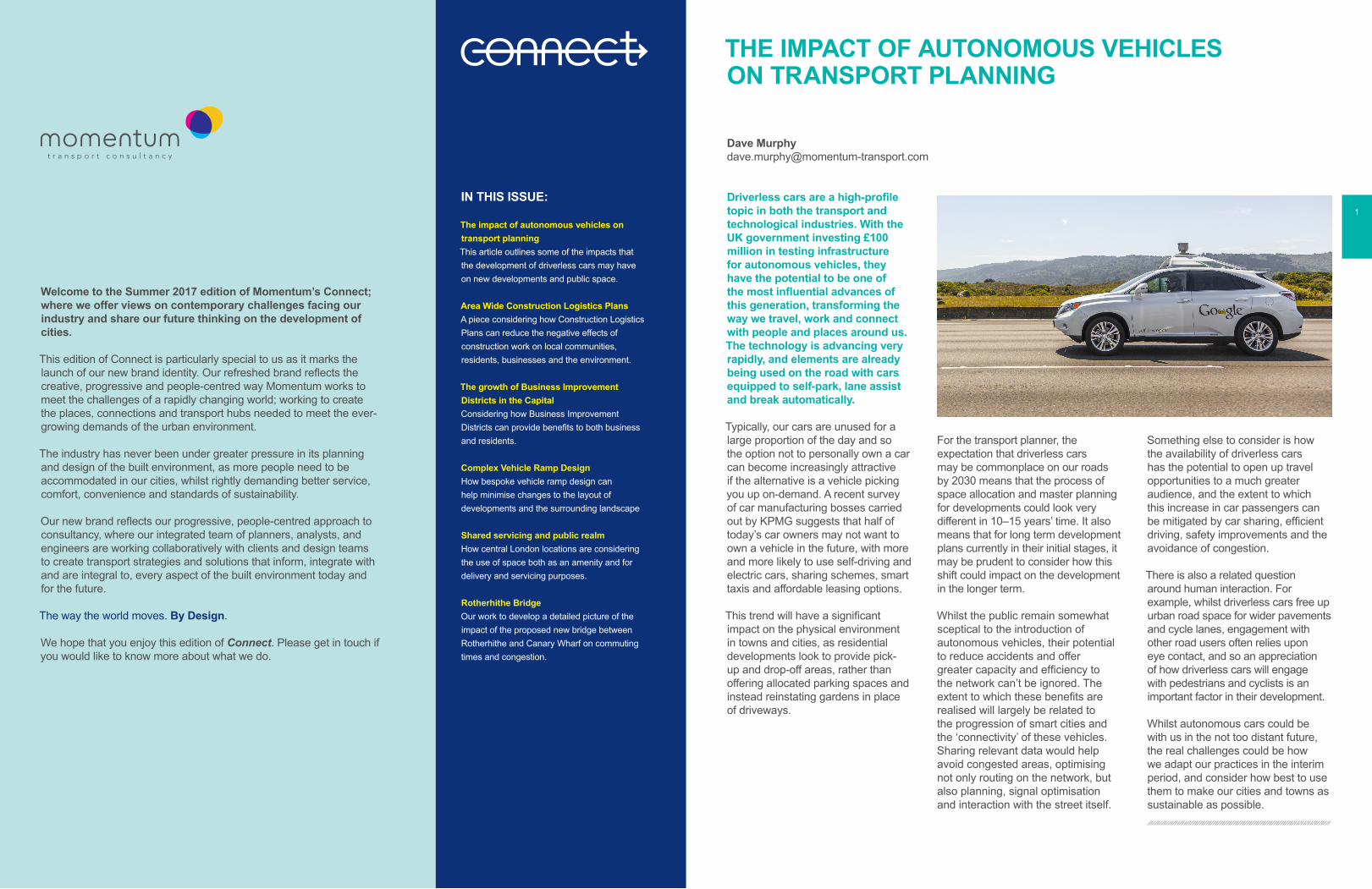
Driverless cars are a high-profile topic in both the transport and technological industries. With the UK government investing £100 million in testing infrastructure for autonomous vehicles, they have the potential to be one of the most influential advances of this generation, transforming the way we travel, work and connect with people and places around us. The technology is advancing very rapidly, and elements are already being used on the road with cars equipped to self-park, lane assist and break automatically.
Typically, our cars are unused for a large proportion of the day and so the option not to personally own a car can become increasingly attractive if the alternative is a vehicle picking you up on-demand. A recent survey of car manufacturing bosses carried out by KPMG suggests that half of today’s car owners may not want to own a vehicle in the future, with more and more likely to use self-driving and electric cars, sharing schemes, smart taxis and affordable leasing options.
This trend will have a significant impact on the physical environment in towns and cities, as residential developments look to provide pick-up and drop-off areas, rather than offering allocated parking spaces and instead reinstating gardens in place of driveways.
For the transport planner, the expectation that driverless cars may be commonplace on our roads by 2030 means that the process of space allocation and master planning for developments could look very different in 10–15 years’ time. It also means that for long term development plans currently in their initial stages, it may be prudent to consider how this shift could impact on the development in the longer term.
Whilst the public remain somewhat sceptical to the introduction of autonomous vehicles, their potential to reduce accidents and offer greater capacity and efficiency to the network can’t be ignored. The extent to which these benefits are realised will largely be related to the progression of smart cities and the ‘connectivity’ of these vehicles. Sharing relevant data would help avoid congested areas, optimising not only routing on the network, but also planning, signal optimisation and interaction with the street itself.
Something else to consider is how the availability of driverless cars has the potential to open up travel opportunities to a much greater audience, and the extent to which this increase in car passengers can be mitigated by car sharing, efficient driving, safety improvements and the avoidance of congestion.
There is also a related question around human interaction. For example, whilst driverless cars free up urban road space for wider pavements and cycle lanes, engagement with other road users often relies upon eye contact, and so an appreciation of how driverless cars will engage with pedestrians and cyclists is an important factor in their development.
Whilst autonomous cars could be with us in the not too distant future, the real challenges could be how we adapt our practices in the interim period, and consider how best to use them to make our cities and towns as sustainable as possible.
1

AREA WIDE CONSTRUCTION LOGISTICS PLANS
Roderick [email protected]
Construction Logistics Plans (CLPs) have long been a prerequisite of planning applications for new developments. CLPs signify the commitment of developers at the planning stage, and through their subsequent development, can help to mitigate the transport impacts of construction work on local communities, residents, businesses and the environment, whilst providing reassurance to the planning authority that disruption at and around a site will be minimised and mitigated.
Croydon Town Centre is undergoing a transformation with substantial demolition, refurbishment and new construction projects planned between 2017 and 2021. Whereas mitigation measures employed at individual sites may be proportionate and scaled, mitigating the cumulative impacts of multiple construction projects in a single local authority area, programmed over a sustained period of time, represents a significantly greater challenge. The London Borough of Croydon has implemented a town centre construction logistics plan in order to manage and mitigate any potential impacts. Momentum has been attending the Croydon Town Centre Construction Logistics Plan Forum meetings to monitor the development of the CLP and determine future developer opportunities and requirements.
The Croydon Town Centre Construction Logistics Plan is an area wide plan involving the local authority, Transport for London, developers, utilities companies and local businesses. The CLP encourages collaborative working practices amongst all stakeholders, in order to implement a co-ordinated long-term construction transport strategy. Developers signing up to an area wide plan are requested to provide construction activity data for their specific site, which includes updated construction programmes, volumes of construction vehicle movements and origin and destination data and planned on-street works. This information enables the local authority to forecast and monitor construction traffic flows on a month-by-month basis, consider routeing options and monitor construction activity on the local road network. Through our work supporting Land Securities with its Nova proposals at Victoria, Momentum has also been heavily involved in TfL-led regular Victoria area construction planning meetings, which very closely mirrored the arrangements in Croydon
The aim of the approach in Croydon is to reduce the congestion, pollution and noise impacts of the construction works on local residents, businesses and the wider environment. For this project, three key areas of focus were identified as:
Strategic loading and holding opportunities; for example, holding sites located outside the centralised area allow contractors to stop temporarily, offering better management of vehicle movements and a reduction in final journey times to site, and ultimately offering better on-site management;
› Co-ordinated utilities planning; utilities planning offers an opportunity for developers and service providers to co-ordinate gas, water, sewage and electricity supplies under one time period, reducing disruption on the local road network, and avoiding repetitive works on the public highway;
› Enhanced safety and environment procedures; information relating to site activities such as the use of crushed concrete, plant registration, early doors agreements, use of considerate contractors, innovative training practices such as elite marshalling and the employment of cycle and walking champions can significantly improve the environment around a construction site or a wider area as a result of multiple or adjacent construction projects.
The process hinges on developer communication, contractor integration and the sharing of information. This approach may represent the beginning of a cultural change in the way construction logistics is planned and construction projects are managed and delivered by developers and contractors.
Momentum welcome this shift towards a collaborative approach to construction logistics planning, as a mechanism that both benefits the local environment and wider community, whilst also potentially saving costs by encouraging more efficient working practices and reducing deliveries.
›
›
›
3

CONSIDERING THE GROWTH OF BUSINESS IMPROVEMENT DISTRICTS (BIDS) IN THE CAPITAL
A Business Improvement District (BID) is a defined area in which an additional levy is charged on all business rate payers, which allows local stakeholders to develop projects that will benefit businesses and the local area and help to promote a sense of “place”. As business-led and business funded bodies, BIDs can provide benefits such as business cost reductions through reduced crime or joint procurement, as well as more generally facilitating improved community engagement and a better balance between the needs of residents and the needs of business.
The first BID was established in Toronto in the 1960’s, in the Bloor West Village Business Improvement Area. The concept became increasingly popular in the UK following the Town Centre Movement (TCM), which relied on voluntary business contributions as a mechanism for securing a sustainable income for local areas. In England, BIDs were introduced through legislation in 2003 and by February 2017 there were 270 BIDs in the UK.
Responding to the growing population and associated business activity in the Capital, there are currently more than 50 BIDs across London, helping to accommodate shrinking public budgets and to allow for better relationships between government and entities like Transport for London (TfL). The Cheapside BID was the first in the City of London, and proved how popular such an approach can be with 84% of local businesses voting to pay the additional contribution.
The New West End Company is one of the largest BIDs in Europe, bringing together the commercial interests of property owners such as Land Securities and Frogmore, and over 600 retailers and West End businesses to collectively contribute over £700,000 annually. All of these stakeholders work closely with the Mayor of London, Transport for London, Westminster City Council, the Metropolitan Police and local neighbours to manage and develop this crucial retail area in London’s West End.
However, concerns have been raised that BIDs are becoming a local council’s default option, particularly on large scale new development, which can lead to existing businesses being priced out of an area through increases in general costs like rents and the business rate precept for major projects, as well as the higher BID contributions.
An alternative approach to BIDs is Treasury Invested Funding (TIF - not to be confused with ‘Transport Innovation Fund’, which was replaced by Urban Challenge Fund in 2010) which began in the United States in the 1950s. TIF looks to capture the future incremental tax revenue over a period of 20-plus years, providing funding for public or private projects and infrastructure by borrowing against the predicted future increase in these property-tax revenues. The UK Government is currently looking at this approach for future public sector development and transport projects in London, and considering how public sector land identified for development and transport can be “packaged up” and sold to developers who
would then be exempt from the Community Infrastructure Levy and S106 payments. An example can be found in the Land Value Capture report published recently, which explored how Transport for London could fund projects without relying on Government grant, with the GLA retaining a higher share of locally raised business rates with a view to moving towards 100% retention. Following recommendations from the second London Finance Commission, the Government has also agreed to look at the possibility of giving London more power to use business rates.
Momentum is currently taking an active part in the Hatton Garden BID, working with local stakeholders to improve the public realm for both Hatton Garden and Leather Lane Market and revitalise the area as a world-renowned business and visitor destination, improving the overall visitor experience, and enhancing Hatton Garden’s iconic status as the jewellery quarter in the Capital.
Map of London BIDs 2016, courtesy of Greater London Authority
5
01
01
1100x750 DeepCapping Beam.
95.5
95.4
95.3
95.2
95.1
95.0
94.9
94.8
94.7
94.6
94.5
94.4
94.3
94.2
94.1
95.5
95.4
95.3
95.2
95.1
95.0
94.2
94.1
94.0
1:12
13:1
1:50
1:11
1:44
1:11 1:39
1:11
1:12
1:11
RS
LS
VE
VE
VE CCTV
S 1.0 G 0.05 H 4.0
KIDDERPORE AVENUE
94.9
94.8
94.7
94.6
94.5
94.4
94.294.3
94.4
94.5
94.6
94.7
94.7
1:8.9
1:9.
8
1:11
.9
1:25
.0
1:9.7
1:13.6
1:12.7
1:7.5
1:30.5
1:11.9
1:40.7
1:10.6
9.24: 19. 24: 1
1:30.5
5.14:1
NOTES
Remarks
Job No
Scale at A3
Drawing No Issue
Drawing Title
Job Title
Client
Rev Date By Chkd Appd
AM000076 M000076-PR-102
1:100
KIDDERPORE AVENUE
CONTOUR PLAN OPTION 2
UPPER BASEMENT RAMP
MOUNT ANVIL
A 22/02/16 First Issue DHG DHGYS
1. Do not scale from this drawing, work tofigured dimensions only.
2. Dimensions are in metres unless statedotherwise.
3. All dimensions are to be checked on siteand the Engineer notified immediately ofany discrepancies prior to commencing theworks.
4. This drawing is based on topographicalsurvey information provided by MurphySurveys (Oct 2015), drawing number1330-01-09.
5. Column details are based on Tully De'athsketches provided on 10th February 2017.
6. Top of kerb levels have not provided in thetopographical survey, a value of 100mmhas been assumed for existing kerbupstands.
7. Items shown in grey are existing or outsidethe scope of this design package.
8. This ramp details supersedes all previousoptions.
Existing highway boundary (LondonBorough of Camden)
Basement Layout (Level B1)
Proposed contours (25mm intervals)
Proposed gradient
Existing contours (25mm intervals)
Existing gradient
Assumed position of structural columns
KEY
DRAFT FORCOMMENT
4.10
4.20
4.30
4.104.104.10
4.204.204.20
4.304.30
1:50
1:50
COMPLEX VEHICLE RAMP DESIGN
Philip [email protected]
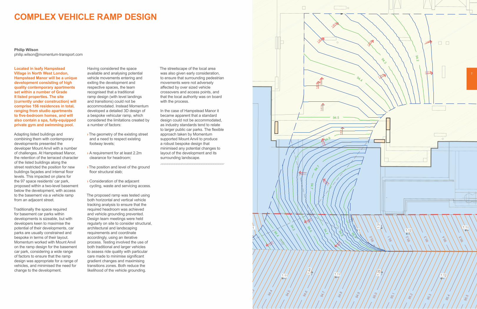
Located in leafy Hampstead Village in North West London, Hampstead Manor will be a unique development consisting of high quality contemporary apartments set within a number of Grade II listed properties. The site (currently under construction) will comprise 156 residences in total, ranging from studio apartments to five-bedroom homes, and will also contain a spa, fully-equipped private gym and swimming pool.
Adapting listed buildings and combining them with contemporary developments presented the developer Mount Anvil with a number of challenges. At Hampstead Manor, the retention of the terraced character of the listed buildings along the street restricted the position for new buildings façades and internal floor levels. This impacted on plans for the 97 space residents’ car park, proposed within a two-level basement below the development, with access to the basement via a vehicle ramp from an adjacent street.
Traditionally the space required for basement car parks within developments is sizeable, but with developers keen to maximise the potential of their developments, car parks are usually constrained and bespoke in terms of their layout. Momentum worked with Mount Anvil on the ramp design for the basement car park, considering a wide range of factors to ensure that the ramp design was appropriate for a range of vehicles, and minimised the need for change to the development.
Having considered the space available and analysing potential vehicle movements entering and exiting the development and respective spaces, the team recognised that a traditional ramp design (with level landings and transitions) could not be accommodated. Instead Momentum developed a detailed 3D design of a bespoke vehicular ramp, which considered the limitations created by a number of factors:
The geometry of the existing street and a need to respect existing footway levels;
A requirement for at least 2.2m clearance for headroom;
The position and level of the ground floor structural slab;
Consideration of the adjacent cycling, waste and servicing access.
The proposed ramp was tested using both horizontal and vertical vehicle tracking analysis to ensure that the required headroom was achieved and vehicle grounding prevented. Design team meetings were held regularly on site to consider structural, architectural and landscaping requirements and coordinate accordingly, using an iterative process. Testing involved the use of both traditional and larger vehicles to assess ride quality with particular care made to minimise significant gradient changes and maximising transitions zones. Both reduce the likelihood of the vehicle grounding.
The streetscape of the local area was also given early consideration, to ensure that surrounding pedestrian movements were not adversely affected by over sized vehicle crossovers and access points, and that the local authority was on board with the process.
In the case of Hampstead Manor it became apparent that a standard design could not be accommodated, as industry standards tend to relate to larger public car parks. The flexible approach taken by Momentum supported Mount Anvil to produce a robust bespoke design that minimised any potential changes to layout of the development and its surrounding landscape.
›
›
›
›
7
7

DR@HL
SVP@HLSVP@HL
SVP@HL SVP@HL
SVP@HLSVP@HL SVP@HL
S/S@HL
27
26
25
24
23
22
21
20
19
18
17
16
15
14
13
12
11
10
526
SSL +93,880FFL +94,130
FFL=SSL +94,130Floor Gully
Floor Gully
01
01
13
RS
LS
VE
VE
VE
VE
VE CCTV
S 1.0 G 0.05 H 4.0
Soil
Ticket Machine
Pavement
Pavement
Gravel
101.58
102.22
102.77
9991.15
KIDDERPORE AVENUE
NOTES
Remarks
Job No
Scale at A3
Drawing No Issue
Drawing Title
Job Title
Client
Rev Date By Chkd Appd
AM000076 M000076-PR-107
1:250
KIDDERPORE AVENUE
VEHICLE TRACKINGOPTION 2
UPPER BASEMENT RAMP
MOUNT ANVIL
A 22/02/16 First Issue DHG DHGPW
1. Do not scale from this drawing, work tofigured dimensions only.
2. Dimensions are in metres unless statedotherwise.
3. All dimensions are to be checked on siteand the Engineer notified immediately ofany discrepancies prior to commencing theworks.
4. This drawing is based on topographicalsurvey information provided by MurphySurveys (Oct 2015), drawing number1330-01-09.
5. Column details are based on Tully De'athsketches provided on 10th February 2017.
6. Items shown in grey are existing or outsidethe scope of this design package.
7. This ramp details supersedes all previousoptions.
8. Refer to M000076-PR-105 & 106 forrespective vertical vehicle tracking profiles.
Existing highway boundary (LondonBorough of Camden)
Vehicle trajectory channel line
KEY
DRAFT FORCOMMENT
PROPOSED DEVELOPMENTPROPOSED DEVELOPMENT
PROPOSED DEVELOPMENTPROPOSED DEVELOPMENT
ROLLS ROYCE PHANTOM ON ENTRY FROM THE WESTExtent of vehicle chassis
Forward gear
VEHICLE TRACK KEY
ROLLS ROYCE PHANTOM ON ENTRY FROM THE EAST
ROLLS ROYCE PHANTOM EXITING TO THE WEST ROLLS ROYCE PHANTOM EXITING TO THE EAST
DR@HL
SVP@HLSVP@HL
SVP@HL SVP@HL
SVP@HLSVP@HL SVP@HL
S/S@HL
27
26
25
24
23
22
21
20
19
18
17
16
15
14
13
12
11
10
526
SSL +93,880FFL +94,130
FFL=SSL +94,130Floor Gully
Floor Gully
01
01
13
RS
LS
VE
VE
VE
VE
VE CCTV
S 1.0 G 0.05 H 4.0
Soil
Ticket Machine
Pavement
Pavement
Gravel
101.58
102.22
102.77
9991.15
KIDDERPORE AVENUE
NOTES
Remarks
Job No
Scale at A3
Drawing No Issue
Drawing Title
Job Title
Client
Rev Date By Chkd Appd
AM000076 M000076-PR-107
1:250
KIDDERPORE AVENUE
VEHICLE TRACKINGOPTION 2
UPPER BASEMENT RAMP
MOUNT ANVIL
A 22/02/16 First Issue DHG DHGPW
1. Do not scale from this drawing, work tofigured dimensions only.
2. Dimensions are in metres unless statedotherwise.
3. All dimensions are to be checked on siteand the Engineer notified immediately ofany discrepancies prior to commencing theworks.
4. This drawing is based on topographicalsurvey information provided by MurphySurveys (Oct 2015), drawing number1330-01-09.
5. Column details are based on Tully De'athsketches provided on 10th February 2017.
6. Items shown in grey are existing or outsidethe scope of this design package.
7. This ramp details supersedes all previousoptions.
8. Refer to M000076-PR-105 & 106 forrespective vertical vehicle tracking profiles.
Existing highway boundary (LondonBorough of Camden)
Vehicle trajectory channel line
KEY
DRAFT FORCOMMENT
PROPOSED DEVELOPMENTPROPOSED DEVELOPMENT
PROPOSED DEVELOPMENTPROPOSED DEVELOPMENT
ROLLS ROYCE PHANTOM ON ENTRY FROM THE WESTExtent of vehicle chassis
Forward gear
VEHICLE TRACK KEY
ROLLS ROYCE PHANTOM ON ENTRY FROM THE EAST
ROLLS ROYCE PHANTOM EXITING TO THE WEST ROLLS ROYCE PHANTOM EXITING TO THE EAST
9

SHARED SURFACES IN LONDON
Amelie [email protected]
To respond to increased spatial constraints in the capital and the drive for an improved public realm for pedestrians, a number of central London locations are considering how space can be used both as an amenity and for delivery and servicing purposes. The design and configuration of shared surfaces needs to consider public space as attractive and comfortable areas for people to enjoy, alongside functional space that provides an important facility for retail and commercial uses.
An example of where the concept of shared space is operating successfully is Borough Market in Southwark, where deliveries are timed to be undertaken in the first part of the day to allow the space to be used solely as public realm later in the day when the majority of visitors and users are expected. Similar approaches have been adopted in Carnaby Street and Covent Garden Market in the West End.
Momentum has worked with Land Securities to develop its proposals at 133 Park Street and 105 Sumner Street in London Borough of Southwark, which received resolution to grant consent in March 2017. The proposals included a shared surface area of public realm, which will also accommodate servicing vehicles at off-peak times. The senior team at Momentum also previously worked with Land Securities to develop a similar shared surface arrangement at the Zig Zag building and Kings Gate in Victoria, which is now complete.
At the Zig Zag building, the delivery and servicing access route is enhanced through the removal of raised kerbs to provide a high quality, attractive shared pedestrian route, which offers an alternative to the busy footway along Victoria Street. For Park Street/Sumner Street, we proposed a shared surface in the central courtyard of the site. The space will be open for large delivery and servicing vehicle movements outside of peak pedestrian hours, allowing the courtyard to be dedicated to the enjoyment of office users and the general public in the morning and evening period as well as during lunchtime.
Such innovative approaches to the use of urban space are of interest to developers as space for on-site delivery and servicing is constrained; particularly in the majority of Inner London boroughs where this has become a planning policy requirement. In many London boroughs it has become vital that new developments manage delivery and servicing activity off-street (where they are able to do so) to mitigate the impact on often already heavily used road networks.
In parallel, new developments are encouraged to promote sustainable modes of transport by providing public realm space and pedestrian connections to transport nodes and major destinations. In a context where urban space is valuable and limited, the possibility to maximise the external space of a new development to accommodate both operational logistics and pedestrian amenities has become an interesting opportunity.
At Momentum, we are considering shared surface strategies across a wide range of projects and making recommendations to clients where appropriate. Of particular interest are projects where site constraints have been identified and there is potential to improve a scheme with the addition of public realm. Working with clients on this type of development, we are able to apply flexible approaches to delivery and servicing timings, highway design and materials, and the size of vehicles, all of which improve the overall development whilst securing a successful planning consent.
11

ROTHERHITHE BRIDGE
There are 32 bridges across the Thames to the west of Tower Bridge in London but only one to the east, resulting in a significant lack of connection across the river. Responding to this connectivity gap, Rotherhithe Bridge began as a proposed concept design produced by reForm Architects and engineers Elliott Wood.
An initial study, commissioned by cycling charity Sustrans, had looked at the feasibility of building a pedestrian and cycle bridge over the River Thames between Canary Wharf and Rotherhithe. The findings highlighted that by developing Rotherhithe Bridge from Durand’s Wharf (in Rotherhithe) to the Impounding Lock (in Canary Wharf), and as a result connecting Rotherhithe to the Jubilee Line, the DLR and Crossrail, commuting times and congestion on other parts of the transport network could be significantly reduced. The study also showed that linking the London Borough of Southwark to Canary Wharf had the potential to deliver important economic benefits for both areas, predicting that by 2020 there could be approximately 2.1 million bicycle and more than 1 million pedestrian journeys each year across the bridge.
Working with reForm and Elliott Wood, Momentum carried out a comprehensive review of the findings from the initial feasibility study, with the purpose of producing a more detailed picture of the impact of the proposed new bridge on commuting times and congestion in the area. Using 2011 Census data and the corresponding population weighted centroids, and extending the length of the “potentially cyclable” trips to represent a more realistic cycling catchment, we were able to predict that bicycle journeys each year (noted in the initial study) could be increased by up to 25%, with more than 2.5 million cycle trips being made per annum across the new Rotherhithe Bridge from 2020 onwards. Further work was also undertaken to analyse non-commuter travel such as to education, leisure and retail destinations. In addition, there are a number of major development sites proposed in the locality, at Wood Wharf, North Quay and Canada Water. Considering these in the context of the new bridge, it became evident that the level of usage by both cyclists and pedestrians was likely to increase even further, with flows becoming more balanced compared with the current land-use predictions of the morning journeys (mainly from the south residential areas to the employment in the north) and the reverse in the evening.
This revised package of analysis enabled Momentum to develop a comprehensive model of usage, which indicated that the new bridge could form a hugely important element of London’s sustainable transport network.
The Mayor has now supported the acceleration for the provision of the new pedestrian and cycling bridge linking Rotherhithe and Canary Wharf. The new Rotherhithe Bridge will enable people living and working to the south of the river to link to Cycle Superhighway 3, as well as linking the north of the river more effectively to the Thames Path and the planned cycle routes throughout Southwark.
With a requirement from the Port of London Authority for a clear span of 184m it will be the longest opening bascule bridge in the world. A competitive procurement process is now underway and subject to funding, availability of land and relevant approvals, the new bridge could be open by as soon as 2020.
13

image credit: …
As one of London’s leading transport consultancies we specialise in:
London development planning and engineering
Global sports stadia and major events
International stations and transport interchanges
›
›
›
Clerkenwell House23 Hatton WallLONDON, EC1N 8JJ
t +44 (0)20 7242 0228e [email protected] momentum-transport.com
@Momentum_TP_Ltd


![Autonomous vehicles[1]](https://img.pdfslide.net/doc/110x75/54bf07bb4a7959cb478b4592/autonomous-vehicles1.jpg)