Embed Size (px)
Citation preview
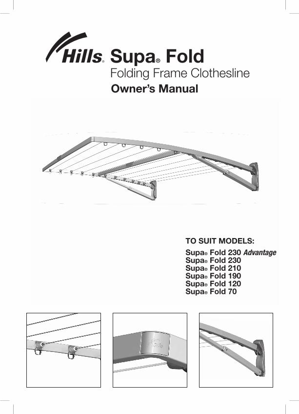
Supa® Fold Folding Frame Clothesline Owner’s Manual
TO SUIT MODELS:Supa® Fold 230 Advantage Supa® Fold 230 Supa® Fold 210 Supa® Fold 190 Supa® Fold 120 Supa® Fold 70

CongratulationsCongratulations on the purchase of your Supa® Fold Folding Frame Clothesline, which will bring you many years of trouble free and efficient drying.
It is important that you read this Owner’s Manual thoroughly before installation and use. In this way you will benefit from all the design features and enjoy safe use of the product.
Thank you for choosing Hills.
Warning• Do not allow children or pets to swing on
the Clothesline or items of laundry.
• Ensure when raising and lowering your Clothesline that bystanders (in particular children) are standing well clear.
• Do not use for any purpose other than to hang and dry washing.
• Do not use your Clothesline if parts are worn or damaged.
• Do not allow the frame to lower in an uncontrolled manner as damage or injury may result.
• Patents and Registered Designs apply to this product.
For any assistance in Australia call Hills Consumer Advice on 1300 300 564 (cost of a local call) during normal business hours or visit www.hills.com.au
For any assistance in New Zealand call 09 262 3052 during normal business hours.
Consumer AdvicePlease retain this Owner’s Manual. Record the following information from the carton for future reference.
Product Number: FD
Date of purchase:
Name and location of store:
Supa® Fold 230 Advantage/ Supa® Fold 230
Part name Qty.
Mount Bracket Assembly - LH 1
Mount Bracket Assembly - RH 1
Arm Outer Assembly - LH 1
Arm Outer Assembly - RH 1
Arm Inner Assembly - LH 1
Arm Inner Assembly - RH 1
Spreader Bar Outer 1
Spreader Bar Inner 1
Corners 4
Line Assemblies 11
Packing Blocks 2
Hex Key - 6mm 1
Hex Key - 5mm 1
Supa® Fold 230 Accessory Bag: 1
Cover Caps 22
Large Bayonet Caps 4
Small Bayonet Caps 4
Owner’s Manual 1
Unpacking the Supa® FoldFolding Frame Clothesline1. Open the front face of the carton (all carton materials can be recycled). 2. Unclip the plastic Packing Blocks that secure the clothesline within the carton. Note: the lid on one of these Packing Blocks holds the Hex keys used for assembly. You can remove and hang the lid to keep your Hex keys in a safe place! 3. Check all components are in the carton (refer to tables below for your model).
Introduction

3
Pack Contents
Supa® Fold 210
Part name Qty.
Mount Bracket Assembly - LH 1
Mount Bracket Assembly - RH 1
Arm Assembly - LH 1
Arm Assembly - RH 1
Spreader Bar 1
Corners 2
Line Assemblies 10
Packing Blocks 2
Hex Key - 6mm 1
Hex Key - 5mm 1
Supa® Fold 210 Accessory Bag: 1
Cover Caps 20
Large Bayonet Caps 2
Small Bayonet Caps 2
Owner’s Manual 1
Supa® Fold 190
Part name Qty.
Mount Bracket Assembly - LH 1
Mount Bracket Assembly - RH 1
Arm Assembly - LH 1
Arm Assembly - RH 1
Spreader Bar 2
Corners 2
Line Assemblies 6
Packing blocks 2
Hex Key - 6mm 1
Hex Key - 5mm 1
Supa® Fold Accessory Bag: 1
Cover Caps 12
Large Bayonet Caps 2
Small Bayonet Caps 2
Spreader Accessory Bag: 1
Spreader Handle 1
Spreader Joiner 1
Hex Key - 4mm 1
M6 x 16.0 Bolt 2
Owner’s Manual 1
Supa® Fold 120 / Supa® Fold 70
Part name Qty.
Mount Bracket Assembly - LH 1
Mount Bracket Assembly - RH 1
Arm Assembly - LH 1
Arm Assembly - RH 1
Spreader Bar 1
Corners 2
Line Assemblies 6
Packing Blocks 2
Hex Key - 6mm 1
Hex Key - 5mm 1
Supa® Fold Accessory Bag: 1
Cover Caps 12
Large Bayonet Caps 2
Small Bayonet Caps 2
Owner’s Manual 1

4
Installation
Select a suitable location1. Select a suitable location for either wall
or post mounted installation. If wall mounted - ensure area is free from pipes and other obstructions. If post mounted - you will need to purchase the Hills Ground Mount Kit to suit your Supa® Fold Clothesline.
2. Ensure you have left sufficient space surrounding the Clothesline (Fig. 1). We recommend 0.5m each side and 1m in front, as well as sufficient space to clear the eaves of the house (refer to pg.7)
Product Dimensions
Product Width (mm)
Depth (mm)
Supa® Fold 230 Advantage 2270 1500
Supa® Fold 230 2270 1500
Supa® Fold 210 2270 1500
Supa® Fold 190 3420 780
Supa® Fold 120 2270 780
Supa® Fold 70 1270 780
Fig. 1
1.0m
0.5m
Depth
Wid
th
Ensure area isfree from pipes or obstructions

5
Installation
Fig. 2a
Slide Outer Cover upwards.
Slide Outer Cover away from bracket to remove.
Right Hand Mount Bracket Assembly shown.
This Assembly is used in models Supa® Fold 210,190, 120 and 70.
Inner Cover
Outer Cover
Step 2
Fig. 2b
Slide Outer Cover upwards.
Slide Outer Cover away from bracket to remove.
Right Hand Mount Bracket Assembly shown.
This Assembly is used in models Supa® Fold 230 Advantage and 230.
Outer Cover
Inner Cover
Remove Outer Covers from Remove the plastic Outer Cover mouldings. Removing the Outer Cover moulding allows access to the mount holes in the mount brackets (Fig. 2a and 2b).
Note: The Inner Cover mouldings are secured using screws and do not need to be removed.
Step 1
Step 2
Step 1
Mounting Brackets

6
Fixing to a wallMark position of Mount Bracket hole centres on the wall. Refer to Fig.3 to install your brackets.
Suggested method
• Ensure the selected area is free from pipes and other obstructions.
• Mount one bracket assembly first and use this to align the other bracket.
• Hold brackets against wall and use them to mark the hole centres.
• Ensure brackets are vertical and align horizontally, (a spirit level and a straight edge will help) (Fig. 3).
• Ensure there is a minimum 400mm clearance from the top of the brackets to any overhead obstructions including eaves, gutters etc. to allow for upward movement of frame (Fig. 4).
Note: If you are replacing an existing Hills Folding Frame product, the mount hole centres may be the same. Therefore your new Supa® Fold Folding Frame Clothesline may be able to utilise the existing fasteners provided they are suitable and in good condition.
‘Mount Hole Centres’
Product Centres(mm)
Supa® Fold 230 Advantage 2200
Supa® Fold 230 2200
Supa® Fold 210 2200
Supa® Fold 190 3350
Supa® Fold 120 2200
Supa® Fold 70 1200
Mount Hole Centres
Spirit LevelStraight
Edge
Wall Bracket
Rec
omm
end
ed M
ount
ing
Hei
ght
Use
rs H
ead
Hei
ght
Plu
s 50
mm
Fig. 3
Installation

7
Ground Level
50mm
User’s Head Height
Fig. 4
• User’s Head Height = Top of Bracket• Recommended Clearance = User’s Head Height + 50mm
Top of Bracket
Min
imum
400
mm
cle
aran
ce
abov
e b
rack
et
Installation

1. Drill holes in wall.
Installation method
A. Masonry fasteners are included with this product. Note: these fasteners are designed only for installation in sound masonry walls. If these fasteners are not suitable for your wall or you have any doubt, consult your local hardware store for advice.
B. If you are using these masonry fasteners, drill a 10mm hole using a masonry drill (Fig.5).
C. Clear holes of dust and debris.
8
2. Secure Mount Brackets
Locate mount bracket assembly over holes in wall, insert masonry fasteners and secure as per diagram below (Fig.6).
10 Masonry Drill 4 Holes
Fig. 6
Fig. 5
Fig. 7
Masonry Fastener (supplied)
3. Ensure threads do not protrude more than 4-5mm or interference with Outer Covers may occur (Fig 7).
Wall
4-5mm
WallBracket
Installation
9
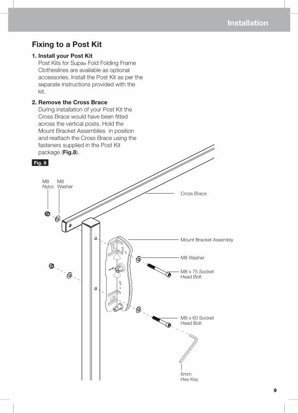
Fixing to a Post Kit1. Install your Post Kit Post Kits for Supa® Fold Folding Frame Clotheslines are available as optional accessories. Install the Post Kit as per the separate instructions provided with the kit.
2. Remove the Cross Brace During installation of your Post Kit the Cross Brace would have been fitted across the vertical posts. Hold the Mount Bracket Assemblies in position and reattach the Cross Brace using the fasteners supplied in the Post Kit package (Fig.8).
9
Installation
Fig. 8
Mount Bracket Assembly
M8 Washer
M8 x 75 Socket Head Bolt
M8 x 60 Socket Head Bolt
M8 Washer
M8 Nyloc
Cross Brace
6mm Hex Key

10
Assembly
1. Fit Arms to Mount Brackets (Fig.9) A. Fit arm assembly to Mount Bracket Assembly, ensuring Arm and Strut Ends engage with the Pivots. Ensure Line Tie- Offs are facing inwards.
B. Secure arms using Bayonet Caps Note: the larger Bayonet Cap is used to secure the Arm End and the smaller Bayonet Cap is used to secure the Strut End.
C. Lock Bayonet Caps using 6mm Hex Key supplied, by turning clockwise until a slight ‘click’ is felt or heard.
D. Repeat for the other side.
E. If assembling Supa® Fold 230 Models repeat the process for the shorter, Inner Arm assemblies.
Fig. 9
Large Bayonet Cap
Arm End
Pivots Dotted line indicates Inner Arm for Supa Fold 230 models
6mm Hex Key
Strut End
Strut
Line Tie-Offs facing inwards
Arm
Small Bayonet Cap

1111
Assembly
2. Assemble the Spreader Bar (Supa® Fold 190 only) The Spreader Bar is pre-assembled in all models except the Supa® Fold 190, which requires the following assembly.
A. Assemble the Spreader Bars using the Spreader Joiner and Spreader Handle (supplied in Spreader accessory bag).
B. Insert Spreader Joiner into one Spreader Bar, align mount holes and loosely secure Spreader Handle using M6 x 16.0 low profile socket bolt (Fig.10).
Spreader Bar
SpreaderHandle
M6 x 16.0
SpreaderBar
Fig. 11
4mm Hex Key
4mm Hex Key
SpreaderJoiner
C. Assemble second Spreader Bar (Fig.11) and secure using M6 x 16.0 low profile socket bolt.
D. Tighten both bolts using 4mm Hex Key supplied in the Spreader Accessory Bag.
Fig. 10

12
3. Assemble Corners into Spreader Bar A. Insert Corners into both ends of Spreader Bar, ensure the orientation of the corners and handle match.
B. To secure the Corners, remove the Corner Caps.
C. Tighten M6 socket head bolt using 5mm Hex Key.
D. If assembling the Supa® Fold 230 models, repeat for the Inner Spreader Bar.
E. Do not re-assemble Corner Caps yet.
Insert screwdriver into slotand gently lever open.
Corner Cap
5mm Hex Key
M6 Socket Head Bolt
SpreaderBar
Assembly

13
4. Assemble Spreader Bar to Arms A. Raise both Arms to the ‘horizontal’ position (refer to Operation section, page 17).
B. Insert the Corners into Arm Ends.
C. Ensure the Handle moulding is the correct way-up (Fig.12).
D. Secure both Corners by tightening M6 socket head bolt using 5mm hex key (Fig.13).
E. If assembling the Supa® Fold 230 models, repeat for the Inner Spreader Bar.
F. Snap on all Corner Caps (Fig.14).
Fig. 12
Fig. 13 Fig. 14
Handle must bethis way up
Corner Cap
CornerArmCornerArm
M6 Socket Head Bolt
5mm Hex Key
Spreader Bar
Assembly
Spreader Bar

5. Re-Attach Outer Cover Mouldings A. Locate the pins on Outer Cover mouldings with the keyed slots in the Mount Bracket and slide down to secure.
Fig. 15
14
Assembly
Slide down to attach.
Locate and Engage pins.
Right Hand Mount Bracket Assembly shown.
Step 2
Step 1

15
To Attach Line Segments
15
Line Assembly
Step 1
Your individual line segments are supplied partially sub-assembled like this.
Step 4
Attach this end of the Line assembly to a Tie-Off on the Right Hand Arm. Bayonet fit the Cover Cap by rotating clockwise until ‘click’ is felt. Repeat for all lines.
Step 2
Add one Cover Cap to each line segment in the orientation as shown.
Step 3
Ensure the Cover Cap, Line, Spring and Retainer are assembled like this.
Step 6
Insert the line down through the front slot of the Tensioner as shown, pull through line until desired tension is reached. (DO NOT OVER TENSION, as you can distort the Frame).
Fit the second Cover Cap onto the other end of the line, (ensure correct orientation)
Step 6Step 5

16
Line Assembly
To Attach Line Segments (Continued)
Step 7
Loop the line around the rear groove of the Tensioner and pull tight to prevent line slipping.
Step 10
Trim off any excess line flush with end of Cover Cap as shown.
We reccommend trimming excess line after a few loads of washing have been hung to allow ‘pre-stretch’ of line to occur.
Step 8
Feed the line up and back through the front slot of the Tensioner and pull tight.
Step 9
Feed end of line through the Cover Cap and Bayonet fit by rotating clockwise until a slight ‘click’ is felt.
Note: A short video showing the attachment of line segments is available for viewing on the Hills website: www.hills.com.au
Line Re-Tensioning
To re-tension lines if required A. Remove Cover Cap on the Left Hand arm, by rotating anti-clockwise.
B. Untie the existing line.
C. Repeat Steps 6 to 10 as described above (DO NOT OVER TENSION, as you can distort the frame).
Step 9
1717
Operation
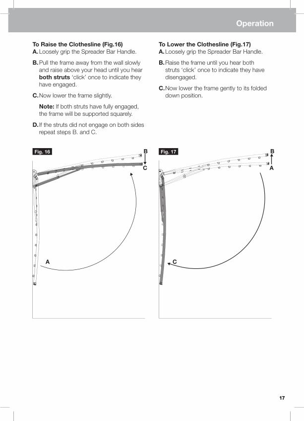
To Raise the Clothesline (Fig.16) A. Loosely grip the Spreader Bar Handle.
B. Pull the frame away from the wall slowly and raise above your head until you hear both struts ‘click’ once to indicate they have engaged.
C. Now lower the frame slightly.
Note: If both struts have fully engaged, the frame will be supported squarely.
D. If the struts did not engage on both sides repeat steps B. and C.
To Lower the Clothesline (Fig.17) A. Loosely grip the Spreader Bar Handle.
B. Raise the frame until you hear both struts ‘click’ once to indicate they have disengaged.
C. Now lower the frame gently to its folded down position.
B
C
Fig. 16 Fig. 17
A
B
A
C

Hills Handy HintsPlace smaller items of clothing on the lines nearest to the wall or posts and work your way outwards for larger items.
When hanging thick or bulky items, you may remove one piece of line to give yourself greater space between lines or lay the item over more than one line.
When you do not expect to fill the capacity of your clothesline, hang your clothes on the outer lines, as this will allow clothes to dry more easily.
Care and MaintenanceRegularly inspect all components and check for wear and tear or damage. Ensure fasteners are secure. If there is any damage, parts should be replaced with original Hills spares. The Clothesline should be repaired before using again.
Your Clothesline should be periodically wiped clean with a damp cloth and mild detergent.
Your Clothesline should be easy to operate, but if left for a period of time it may become more difficult. It is recommended that the clothesline is raised and lowered regularly.
We do not recommend the use of oil or ‘WD’ type lubricants on any part of the Clothesline.
Wipe away any dirt and dust from the telescopic struts with a damp cloth once a month. More regularly in dusty conditions.
To maintain appearance and durability of coating on metal components we recommend a twice yearly application of a reputable brand of car polish or wax.
18
Handy Hints

19
Hills GuaranteeHills Industries Limited undertakes that if any part of its manufacture has failed to operate correctly due to faulty workmanship or defective material, it will repair or replace the part free of cost for a period of TEN (10) years from date of purchase of the article, given fair wear and tear. The PVC line is guaranteed for a period of ONE (1) year. Evidence of unfair usage or incorrect adjustment by the owner will void this promise.
Hills Industries Limited will not be responsible for any costs in connection with freight or postage, or for expenditure necessary to dismantle the article, replace the part in position and re assemble the article.
This guarantee is in addition to any rights or remedies conferred on the consumer by Trades Practices Act or state laws.
As a proudly Australian company we are committed to provide you complete customer satisfaction. If you have questions about this product or find there are missing or damaged parts please call Hills direct on 1300 300 819 (cost of a local call) for assistance during normal business hours.
Hills Industries Limited do not recommend the application of a ‘canopy’ on any of their outdoor dryer range.
Unless any addition or attachment to this product has Hills specific approval or is sold as a Hills Supa® Fold product the warranty on this product is waived. The product is designed to perform a specific task under established test loads and unauthorised attachments may produce stresses for which the design is not appropriate.
Designs, specifications and colours are subject to change without notice.
Hills Industries Limited A.B.N. 35 007 573 417
Issue June 2007 PD1223b
19
Guarantee
For any assistance in Australia call Hills Consumer Advice on 1300 300 564 (cost of a local call) during normal business hours or visit www.hills.com.au
For any assistance in New Zealand call 09 262 3052 during normal business hours.
Made in China

Hills Industries Limited A.B.N. 35 007 573 417