Embed Size (px)
DESCRIPTION
Super8 Sond Inc. - Sound Recorder I
Citation preview
, --.', , , -!
,
I '
1:=1
SuperB Sound
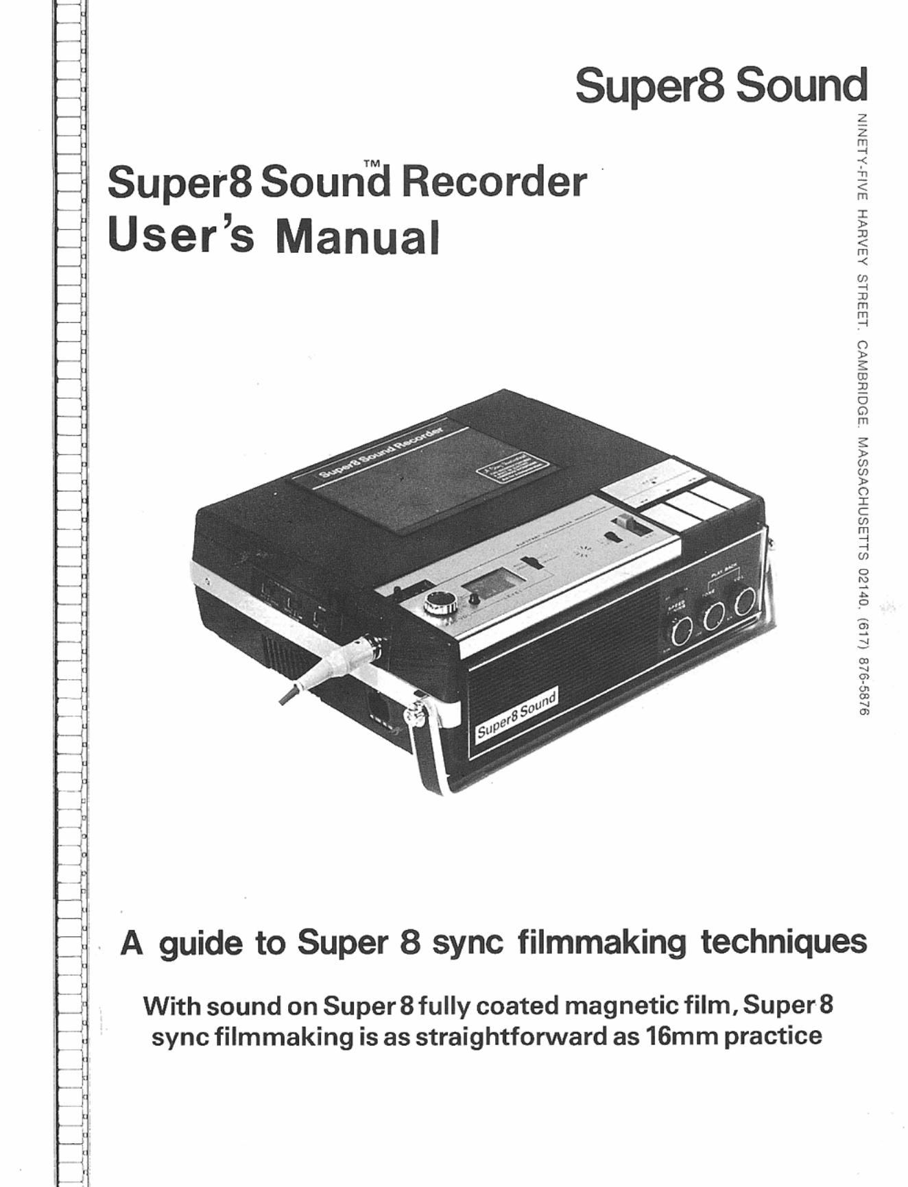
Super8 Soun'(J Recorder · User's Manual
z z ~ < • • < m z > • < m < ~ ~ • m ~
<
~ n z c ~
~ ~ ~
2 -• o
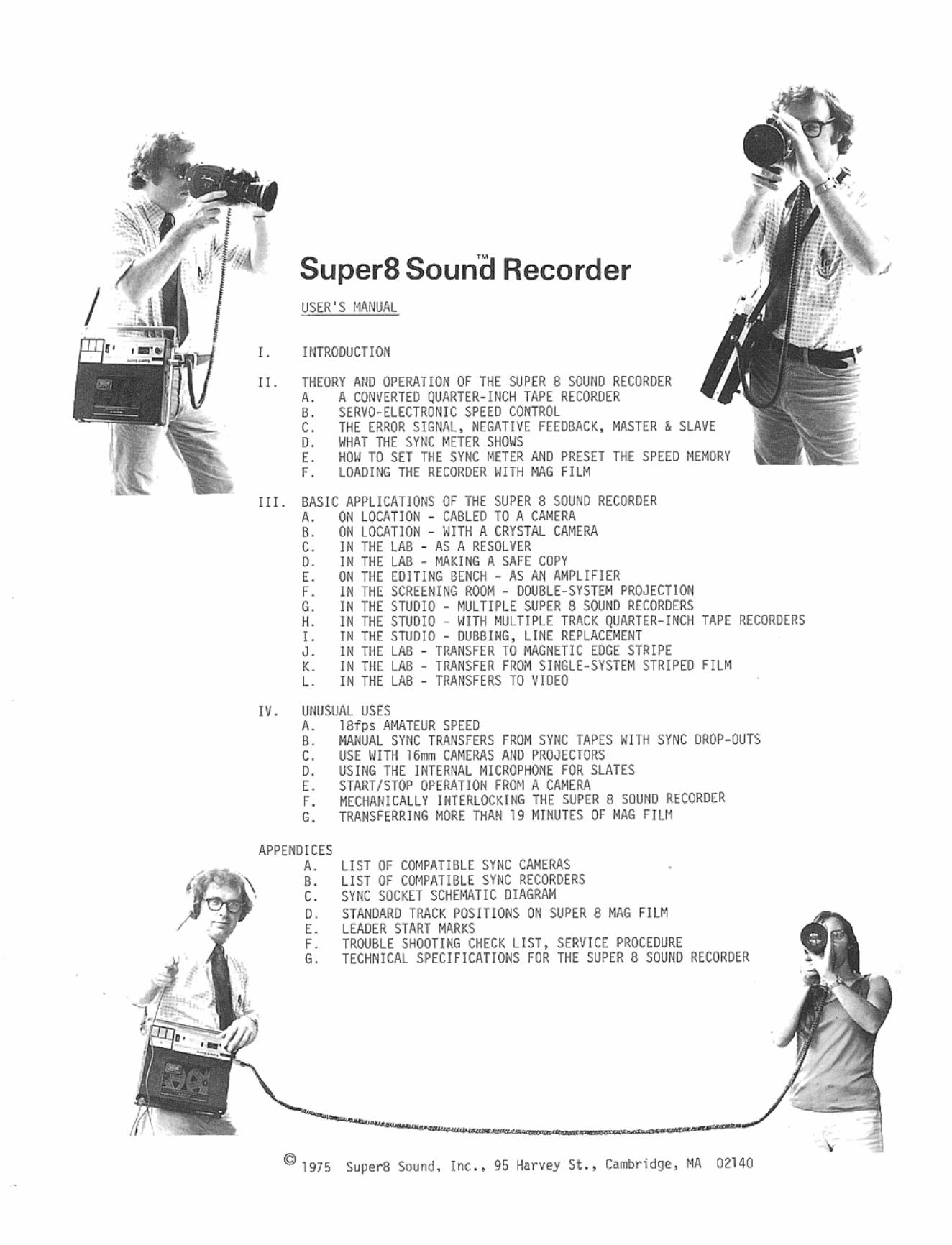
A guide to Super 8 sync filmmaking techniques
With sound on SuperS fully coated magnetic film, Super S sync filmmaking is as straightforward as 16mm practice
SuperS Soun'a Recorder / USER'S I1ANUAL
f. HHRODUCTlOIi
II. THEORY AIIO OPERATION OF THE SUPER 8 sourm RECORDER A. A CONVERTED QUARTER-INCH TAPE RE CORDER B. SERVO-ELECTRONIC SPEED CONTROL C. THE ER ROR SIGNAL, NEGATIH FEEDBACK, MASTER & SLAVE O. WHAT THE SnlC METER SffOWS E. HOW TO SET THE SYNC METER AND PRESET THE SPEED MEMORY F. LOADING THE RECOR DE R WITH MAG FILM
Il l. BASIC APPLICATIONS OF THE SUPER 8 SOUND RECORDER A. O~ LOCATI ON - CABLED TO A CAMERA 8. ON LOCATION - WITH A CRYSTAL CAMERA C. IN THE LAB - AS A RES(}LVER O. IN THE LAB - MAKING A SAFE COPY E. ON THE EDIT ING BENCH - AS AN AMPLI FIER F. I N THE SCREENING ROOM - OOOBLE- SYSTEM PROJECTION G. I N THE STUDIO - MUL TlPLE SUPER B SOUND RECORDERS H. IN THE STUDIO - WITH MULTI PLE TRACK TAPE RECORDERS !. I N THE STUDIO -J. IN THE LAB K. IN THE LAB FILM L. IN THE LAB -
IV . UNUSUAL US ES A. 18fps AMATEUR SPEED B. MANUAL SYNC TRANSfERS FROM SYNC TAPES WITH SYNC DROP-OUTS C. USE WITH 16rrrn CAMERAS AND PROJECTORS O. USING THE INTERNAL MI CROPfiONE FOR SLATES E. START/STOP OPERATION FROM A CAMERA F. MECHANICALLY INTERLOCKING THE SUPER 8 soutm RECORDER G. TRANSFERRING MORE TlWt 19 MINUTES OF MAG FlUl
APPENDICES A. B. c. D. E. F. G.
LIST OF COMPATIBLE SYNC CAMERAS LIST OF CIJ'1PATIBLE SYN C RECORDERS SYNC SOCKET SCHEMATIC DIAGRAM
ON SUPER 8 MAG FILM
" CATI.ONSLIST. SERVICE PROCEDU RE - 1 fOR THE SUPER 8 SOUND RECORDER
01975 SuperB Sound , Inc ., 95 Har vey St., Cambridge, MA 02140
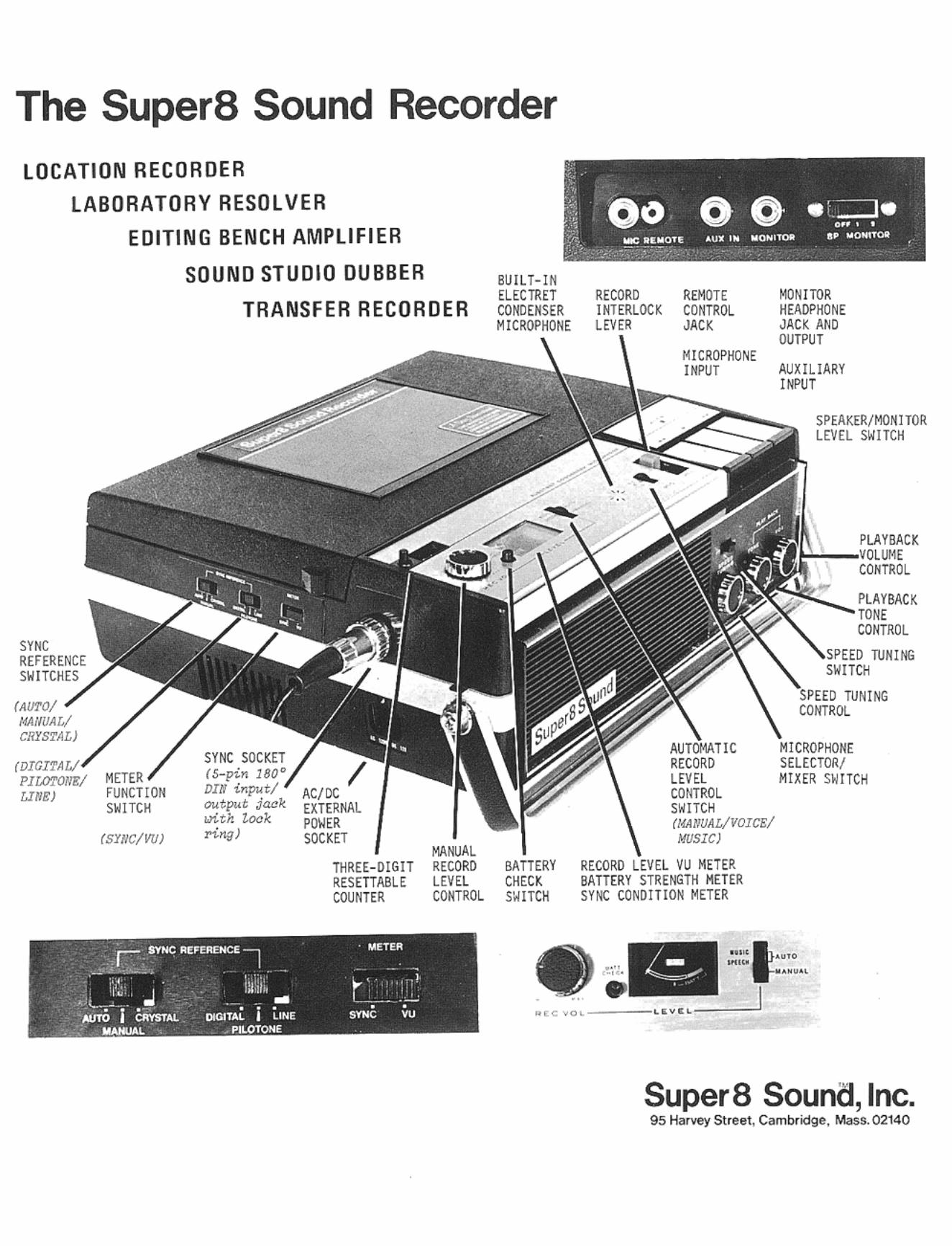
The Super8 Sound Recorder LOCATION RECORDER
LABORATORY RESOL VER
SYNC REFERENCE SWITCHES
(AUTO/ MAI/UALI CRYSTAL)
EDITING BENCH AMPLIF IER
SOUND STUDIO DUBBER
TRANSFER RECORDER
PlLOTONK/ METER LINE) fUNCTION
SWITCH
(SYNC/'IU)
AC/IX EXTERNAl. POWER SOCKET
BU I LT· lN ElECTRET COMlEHSER MICROPHONE
RECORD II(TERLOC~ LEVER
.... , ., ..
•
MICROPHONE INPUT AUXILIARY
METER .. " ~:i~: 'HER mIT METER
I,,"'
SPEAKER/MONITOR LEVEL SWITCH
M1CROPflOHE SELECTOtl I MIXER Sw ITCH
.. '~t'"'· .," ."."'
SuperB Sound, Inc. 9S Harvey Street, Cllmbriclge. Mass.02140
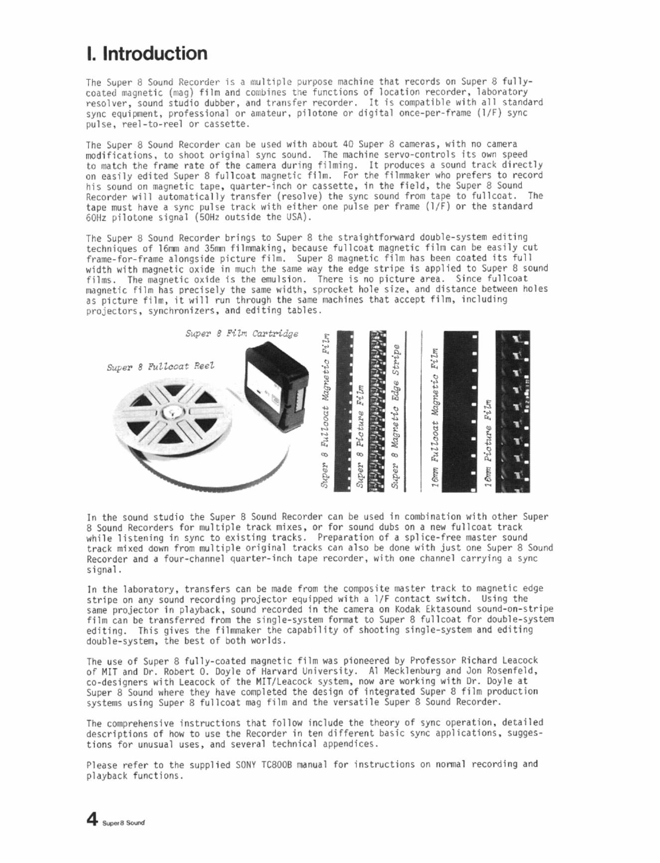
I. Introduction The Suj)l'r 8 Sound ReCOrder is a .. Itiple purpose IIoIch inl' t hat rKords on Super 8 full ycoated 1Iol9~etlc. (II1II9) HIli ~nd coclolnes tile functions of 10'6tlon rI!'Cord@r. labor~tory resolver , sound s t udio (luober, and t ... nsfer recorder. It is cOIIP<Itlble with all st4nd~rd sync equipo:aent. profession.l or luteur , pilotone or digital once-per -fr4l!le (l1F) sync pulse . reel-to-~el or cassette.
The Super 8 Sound Recorder "" be used w1th about 40 Super 8 cameras , with no camen modific4tions, to shoot ort glna l sync sound. The IMchi ne se rvo-cont rols its own speed to mil t ch t he frame rate of the carroe ra during f ilming. It produces a so un d track directly on eUil y e<lited Super 6 fullcou IIIIIgnetlc flh •. For t he fl1nmaker wr.o prefers t o record his sound on ma gneti c tape. quarter-Ind or cassette. In the f ield , ttle Super 8 Sound Recorder will ~u tomatieally transfer ( resolve) the sync sound froon tlpe to ful1coat. The hpe n.lst have a sync pu l st t. ra c~ .. Hh eHher one pulse pe r f ral\t (1/F) or the standard Wlz pilotone si9nal (~z outside t he USA).
The Super 8 Sound RKorder brings to Super 8 the straightfol"olard double-syHeIIl editing techniques of 16nII and 35m fil_Ung . bt<:allse fullcoa t IIIlgnetic filn can be usily cut fra:llt-for-fra~ alongside pietul't fil •. Super 8 -.JgM' tlc filII lias been cOHed its fu ll width with ~gnetic o~ide in "",eh the sail!! .. ay the edge s tr ipe Is applied to Super 8 sound tll.s. Tile ... gnetle o~ide is the tml1s10n. There is no pic ture arn. Since fullcoat IIIoJgnetic til. has prKisely the UIIIe width, sprocket hole s ize, and dhunce betwen holes IS pi cture f ilII, it will run throu9h the saml! ,;oa th!ne; that accep t f il l'!l, ifICluding projlllCtors . synchronizers . and editing tables.
, < t ~ • • } i • • J! ! ~ ~ ~
1 < • • • 1 • • •
In the sound s tudio the Super B Sound Recorder can b.e used in combinHlon with other Super 8 Sound Recorde r s for IUl t/ ple track mh es . or for sound dubS on a new full coat track wh il e lhtening In sync t o exi sting trach. Prep~ration of a splice-free raaste r souM t rack .hed down from Blltiph Or191nal t r~ch can also be done .. Ith j~H one Super 8 Sound RKordcr and ~ four-ch.nnel qu~ rter- Inch t.pe recorder, .. lth one ch~Me l carrying a sync s ignal .
In t ile laboratory . t rans fer s can be made troll the cOlllPOsite .. ster trick to .. gne t ic edge stripe on any sound ncord ing projector equipped .. ith a l/F conuct switch. Using the s_ projector In phyb.Jock. sound recorded In the caraera on I:odlk Ektnound sound-on-s tri pe '11. can be tranSferred frOil t ile slngh!-sys t eoa forw t to Super 8 (ullcNt for double -systen editi ng . Th is gives the fillJllilker tile capabili ty of shooting s ingle-sys t tll'l and editing double -system. t he bes t of both worlds.
The use of Super 8 ful ly-coa ted fI'IIgnetlC fl1m was pioneered by Professor Richard Leacock of MIT and Dr. Robert D. [loyle of Harvard Uni versity. Al Mecklen tlurg and Jon Rosenfeld, CO-designers with Leacock of the MIT/Leacod sys tem. no .. ~re work ing with Dr. Doyle at Super 8 Sou nd .. here t hey have c~1eted t he design of integrated Super 8 film production systeals using Super 8 fullcon .. g f i l II and the versatile Super B Sound Recorder .
The cOllPrehensive inst ruct ions tllat follow include the theory of sfl'Ic operation . deta il ed desc r iptions of how to use the Rt(:order i n ten differen t buic syoe applicati ons . Slll1ge5-tiDns for unusllal uses, .1Id several technical appendices.
Pluse refer to t he supplied SONY TC800B r../Inual for instructions on no ..... 1 rt<:ordl ng and playback func t ionL
4 __ _
II. Theory and Operation of the SuperB Sound Recorder
II . A A CO~~ERTED QUARTER- INCH RECORD(R
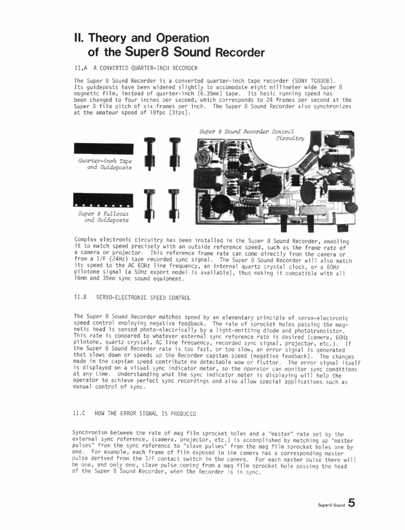
The Syper 8 Soynd Recorder j S ~ converted Quarter- Inch u~e record~r (SONY. TC8IXlB). Its 9uidePO~ts have been widened s1igllt ly to accom<iHe t Ight lIill11!11! te r w,de Super 8 magnetic fl1 _, Instead of quar te r . Inch (6 .35Il10) t.lpe. Its basic runnin9 speed .... s been changed to four inches per st(:ond, which corresponds to 24 frames per second at. the Super 8 til . pitch of si:t fr_s per loch. The Sul'4! r 8 Sound Recorder .150 synchronIzes at the aOll/lle",r speed of 18fps (3Ips).
Quart.r_inoh Tap. WId Ouuu~u
• • • • • • • • Sl<p.or 8 1'l4Hcoot
ar.d Ouid<lp"u"
SI<~r 8 ,s.,~nd fI.'cor<UJr eolltl'O! ~ .. itr!l
toqJ l l'~ e l ectronic circuit r y lias been installed in the Super 8 Sound Recorder. enabling it to ~tch speed predsely wlth.t" outside ",ference sp.eed, such as the f T11IIe rate of a call1l!r,, or proje<::tor . Thts reference fr.tllle rate can cone di rectly fron the c.lIIt ra or fT'Olll a l/r (24Hz) tape recorded sync s ign. l. Tht' s.u!ler 8 Sound Recorder "Ill .lso -atch its speed to the At 60Hz line frequency, an In t er nal quartz crysta l clock, or. 60Hz pl1otone signal (a 50Hz e~pOrt model Is avaihble). thus ~k ln9 it cOO1pati ble .... lth all 16m and 3511111 sync sound equ i pment.
iJ. B S€RVO- ELECTRON 1C SPEED CONTROL
The Super 8 Sound Recorder -atthes speed by an eleor-elll. ry prinCiple of servo-"lectronic s~d control e.lPloying negHIyf' feedback. The ralf' o f wrockf't holes passing the IIIlg · net i c hUd IS sensed pho t O-f' l eclr1cally by a 11ght-em'ttlng diode and pho t otr.nslstor. This Nh! is compared t o .... ha t ever uternal 5Y",; reference rate is desl r e<l (c.mera . 60Hz pi 1 otone, quartz crystal, AC I i ne frequency , recorded sync s i9na I, proJector, etc . ) . If the Super 8 Sound Recorde r rue Is too fast, or t oo slo ... an error signal 1$ generated that s lows dOrm or speeds up the Recorder capstan speed (nega t ive fe edback). The changes "",de In the capstan speed contr ibute no detectabl~ we. or flutte r . Thf' error s i gnal itself is disph.yed on a visu~ 1 sync In.diCUor IE t er , so tilt operator can .cnitor sync condit ions at any tiOll!. lJn.de rs tandlng .ha t the sync irldicator meter is displaying will help the operator to achi eve perfect sync re<ordlngs and aho dl1011 special awllutlons such a s Nnual cont rol of sync.
I I.C HO'~ THE ERRO R SIGNAL IS PRODUCED
Synchronis. be t.een the rate of IIII.g fi 111 sprocket holes and ~ "..aster " rate set by thf' e~ter ... l sync re fer ence. (".ra. projector, etc.) is accompJishe<l by ~tching uo "lIIIste r pulses" from the ~yn( referencf' to ·slave pulses· fT'Olll the illig fll. spratket holn one by one. For exa~l e, edeh frame of flll11 e.pose<l In the e'Gera nas a correspon.ding ... ster pulse derived froa t he IfF conun swacll In t he cult ra. For each m4ster pUlse t hel'i! .111 be one, 'lid only one, slave PIIlse coming fron a IIIg fll. sprocket hole pusln9 the head of t ne Super 8 Souna Recorder ... hf'n th~ Rt'torder Is tn sync.
_._5
Theory
UQN" OR "MASTERn PU LSES - E.G" lIF SWITCH SIGNAL FROM CAMERA
-1--\-~\~-\-~\~-\--\--I:--l~-
"OFF" OR "SLAVE" PULSES FROM MAGNETIC FILM SPROCKET HOLES
fI fI fI fI /\ /\ /\ FLIP/FLOP
aNn ,
I I U U ~ I n n OFF tEXTRA "ONu
PULSE
[1d rn ~ ~ [1d SYNC METER METER SWI NGS
RAPIDLY ACROSS .6.T THIS POINT
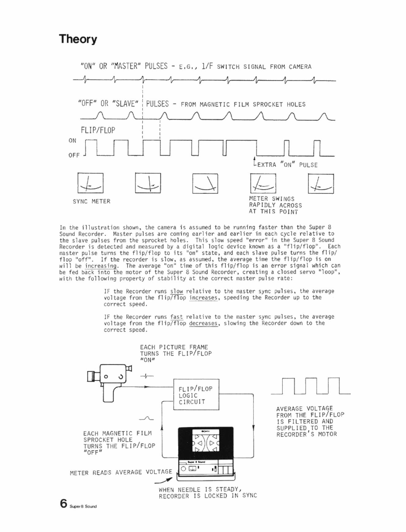
In the i1 1 ustr~tion shown. the Cdmera is assumed to be ru nni ng faster than the Super 8 Sound Recorder. Master pulses are coming ear l ie r and earlier in each cycle relative to the s lave pulses from the sprocket holes. This s low speed "error" in the Super 8 Sound Recorder is detected and measured by a digita l 10g1c device known as a "flip/flop". EaCh master pulse turns t he flip/flop to its "on" state , and each sl ave pulse turns the flip/ flop "off" . If the recorder is slow, as assume<!, the nerage time the flip/flop is on will be increasing. The d~erage "on" t ime of this fli p/flop is an error SigMl which can be fed back 1nto the mo tor of the Super 8 Sound Recorder, creating a closed servo " l oop", with the following property of stability at t he correct master pulse rate:
If the Reco rder runs slow relative to the master sync pulses. the average voltage from the flip/flop inc reases, speeding t he Recorder up to the correct speed.
IF the Reco rder runs fast relative to the master sync pulses, the average voltage from the flip/flop decreases, slowi ng t he Recorder down to the correct speed.
EACH PIC TURE FRAME TURNS THE FLIP/FLOP NON "
I
FLIP/FLOP LOGIC CIRCUIT
-
-
EACH MAGNETIC FILM SPROCKET HOLE TURNS THE FLIP/FLOP "OFF"
AVE RAGE VOLTAGE FROM THE FLIP/F LOP IS FILTERED AND SUPPLIED TO THE RECORDER'S MOTOR
METER READS AVERAGE VOLTAGE
6 _e_
..../ WHEN NEEDLE IS STEADY , RECORDER IS LOCKED IN SYNC
back '"';, ~pr>ea r s, feedback
1 tile negat i ve
of t he error 1
servo if any Sound
Theory
d~'"" ' error r un slow
Negative feedback and the principle of servo-control are thus able to replace the brute force synchronhm achieved by mechanical sprocket drives, and without the flutter that results as sprocket teeth POP in and out of sprocket ho l es. A Cl)dlparison with 160m ful1-coat magnetic film recorders will reyeal hCIW much simpler ilnd more elegant are the 50-called "electronic sprockets" of the Super 8 Sound Recorder,
II .D \.IHAT THE SYNC METER SHOWS
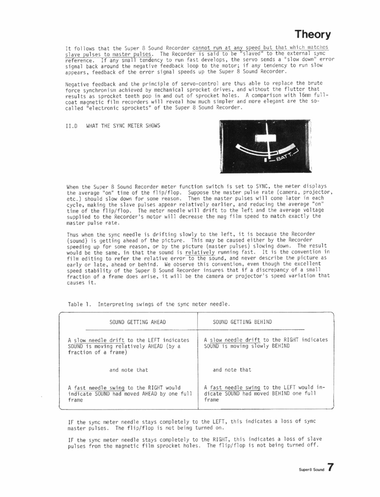
When the Super S Sound Recorder .. eter function switch is set to SYNC, the meter displays the average "on" t ime of the f lip/flop. Sup.,ose the master pulse rate (camera, projector, etc.) should slow down for some reason, Then the master pulses .... 111 corne later in edch cycle, making the slave pulses appear relatively earlier, and reducing the dve rage "on" time of the flip/flop. The meter needle .... ill drift to the left and the average voltage supplied to t he Recorder's motor "ill decrease the III<Ig fl1R1 speed to natch exactly the maste r pulse rate .
Thus when the sync needle is drifting slowly to the left, it is because the Recorder (sound) is getting ahead of t he picture. This may be caused either by the Recorder speeding up for some reason, or by the picture (master pulses) slowing down. The result would be the same, in that the sound is relatively runoing fast. It is the convention in fi lm editing to re fer the re l athe error to the sound. and never describe the picture as early or late. ahead or behind . We observe this convention , even though the e~'el1ent speed stability of the Super 8 Sound Recorder insures that if a discrepancy of a small frac t ion of a frame does arise. it ,,111 be the camera or projector 's speed variation that causes it.
Table 1. Interpreting s .... i ngs of the sync meter needle.
SOUND GETTING ~EAD
and note that
LEFT indicates AHEAD (by a
.... ould one full
SOUND GETTING BEHIND
A slow needle drift to the RIGHT indicates SOUND is moving slowly BEHIND
and note that
t he un would inBEHIND one full
If the sync meter needle stays cOOlpletely to the LEfT. this indicates a loss of sync master pulses. The flip/flop is not being turned on.
If the sync meter needle stays conpletely to the RIGHT, this indicates a loss of slave pu l ses f rom the ~a9netic f ilm sprocket holes. The flip/flop is not being turned off.
_sSouno 7
Theory
I1.E HOW TO SH THE SYNC METER AND PRESET TIlE SPEED MEMORY
the sync meter, set the switche~ to AUTOMATIC and dn ~ppropriate SYNC you sUrt first with the LINE reference, make svre the Recorder is plugged
there \;il1 be no sync signal. Set the METER rUllCTION switch to SYNC, mdg fnm is in the Recorder and start the Recorder. Usually the
n sync, with the ~ter needle steady sOOIeWhere in its range. If the Recorder speed s too high Or too low, the meter needle will drift to one side, then swing rapidly across its full range, then drift back to the same side, etc. Each swing represents one frame gained or lost.
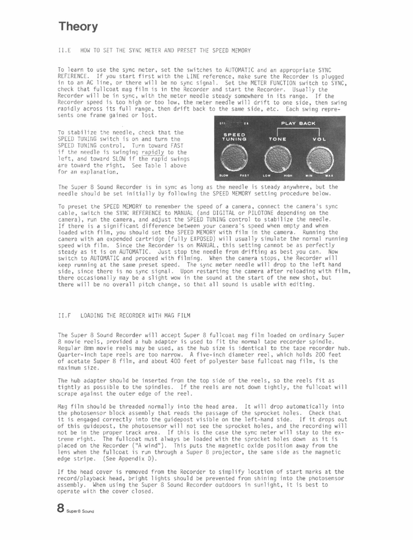
To stab1l1ze the needle, check that the SPEED TU:WIG switch j 5 on and turn the SPEED TU:HNG control. Turn toward fAST if the needle is swinging r:apidly to the left, and to ... ard SLOW 1f the rJpid 5 ... i"gs are tOl,ard the right. See hble 1 ~bove for ~n expla"Hion.
The Super S Sound Recorder i s in ,ym; ~s long as the needle is Heady anywhere, but the needle Should be set Initially by follo ... lng tMe SPEED MEMORV setting procedure belo ....
To preset the SPEED MEf>(JRV to remember the speed of a camera. connect the camera's sync cable. s ... ltch the SVIK REFERENCE to MANUAL (and DIGITAL or I'ILOTONE depending on the camera), run the camera, and adjust the SPEED TUNING control to stabtlize the needle. If there i, d significant difference bet ... een your camera's speed ... hen etnpty and ... hen loaded ... ith film, you should set the SPEED MEMORY ... ith film in the camera. Running the camera ... ith an expended cartridge (fully EXPOSED) ... ill usually Simulate the nonnal running speed ... ith film. Since the Recorder is on MANUAL, this setting cannot be as perfectly steady as it is on AUTOMATIC. Just stop the needle from drifting as best you can. No" Switch to AUTOMATlC and proceed "Hh filming. When the camera stops, the Re.:order .. ill keep running at the Sdwoa preset speed. The syne meter needle .,ill drop to the left hand side, since there is no sync signal. Upon restarting the cawoara after reloading "ith film, there occasionally may be a slight wo" in the sound at the start of the new shot, but there "ill be no overall pitch change, so that all sound is usable "ith editing.
I1.F LOADING THE RECORDER WITH MAG FILM
The Super 8 Sound Recorder will accept Super 8 fulleoaL milg film loaded on ordinary Super 8 Mvie reels, provided a hub adapter is used to fit the normal tape recorder spindle. Regular &rrn movie reels may be used, as the hub size is identical to the tape recorder hub, Quarter-inch tape reeh are too narro". A five-inch diameter reel, \;hich holds 200 feet of acetate Super 8 fllm. and about 400 feet of polyester base fullcoat mil9 fllm, is the ma~imum size.
The hub adapter should be inserted from the top side of the reels. so the reels fit as tightly as possible to the spindles. If the reels are not do"n tIghtly. the fulleoat "ill scrape against the outer edge of the reel,
Mag film should be threaded nonnally into the head area. It will drop automatically into the photosensor block assembly that reads the passage of the sprocket holes. Check that 1t is engaged correctly into the guidepost visible on the left-hand side. If it drops out of this guidepost, the photosensor "ill not see the sprocket holes, and the recording "ill not be i n the proper track area. If this is the case the sync meter \;ill stay to the extretne right. The fulleoat !IlJst al"ays be loaded "ith the sprocket holes do"n as it is placed on the Recorder ("A wind"). Tllis puts the n:agnetic o~jde position a"ay from the lens "hen the fullcOdt is run through a Super 8 projector, the same ~ide as the magnetic edge stripe. (See Appendi~ 0).
It the head cover is fer:JQved from the Recorder to s1mplify 10cHion of start marks H the record/pldyback head, bright lights should be prevented from shining into the photosensor assembly, IOhen using the Super 8 Sound Recorder outdoors in sunlight, it is best to operate ... ith the cover closed.
III. Basic Applications of the SuperB Sound Recorder
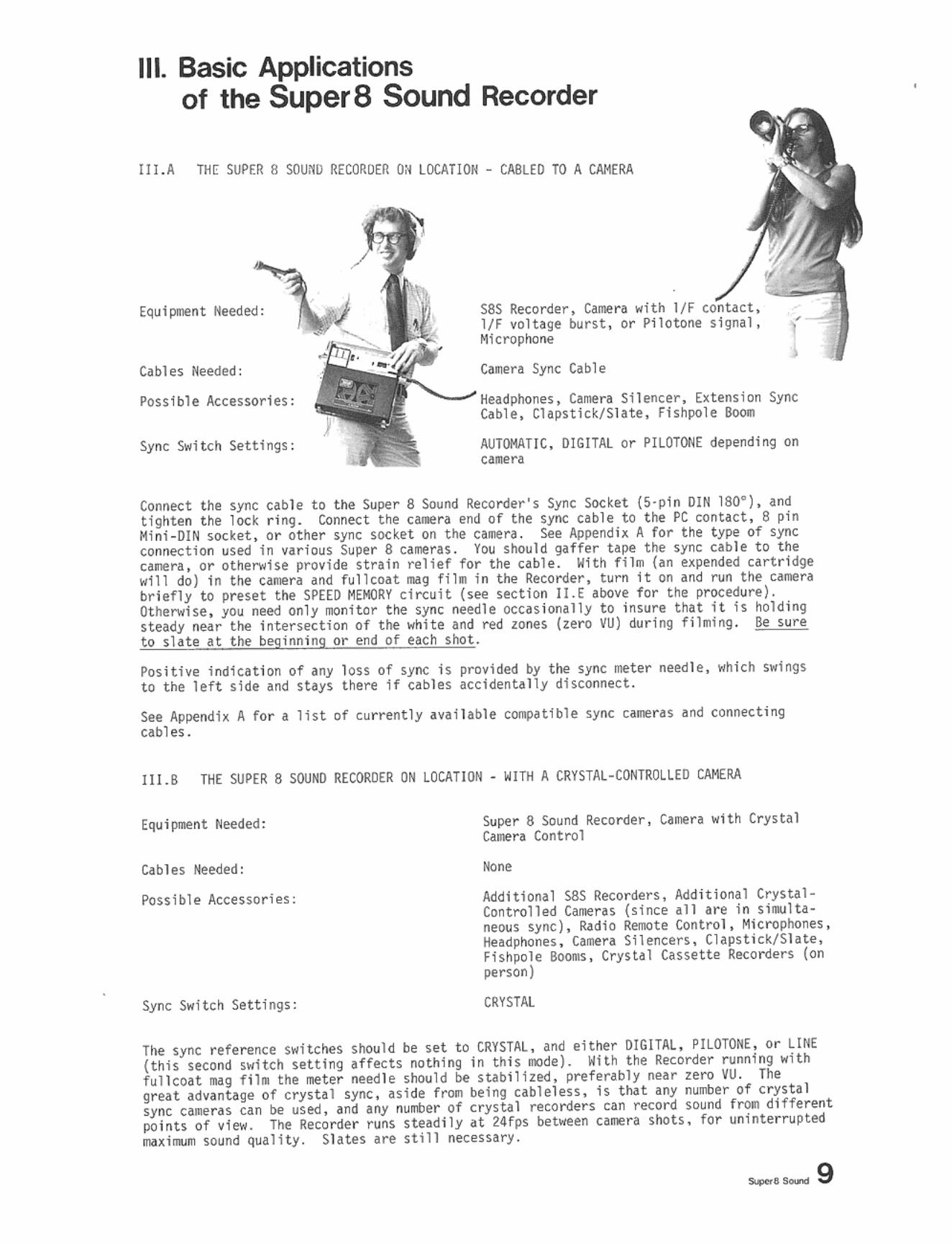
II l. A THE SUPER 8 SOU:fD RECORDER O~ LOCATIOH - CA8LED TO A CAMERA
Cables Needed:
POssi ble Accessories:
Sync Switch Settings:
S8S Recorder, Camere with l /F Iff voltage burst, or Piloto"e Microphone
Caller! Sync IAble • "-~ HeadPhones, Carnera Silencer, Extension Sync
Cable, Clapstid/Slate, Fishpo1e l\ooII
AUTOMATIC. DIGITAL or PllOTON£ depending on ca.era
Connect the sync cable t o the Super 8 SOund Recorder's Sync Socket (S·pin DI N 180' ), and tfgllten the loc~ ri ng . Con!leCt t he C&llera end o f the sync cable to tile PC contact . 8 pin Hinl-DIN socket, or other sync socket on the call1e ra, See Appendix A for the type of sync connection used In nrious Super 8 carlerf,S. You should ~ffer tape the sync cabl e t o t he canera , or otherwise provide strain relief for t he cabl e. With ftlm (an H pem;$ed cartridge w111 do) in the ,amer~ ~nd fullcoat n1119 fil .. in the Recorder, turn 1t on and run t he camer~ briefly to preset the SPEED MEMORY circuit (see section 1l.E aoove for the procedure) . Other.rise, you need only IIOnitor tile sync needle occnlonally to insure t hat i t Is holding steady neu the intersection of tile white and red ~ones (zero VU) ckJ r lng filili ng. Be s ure to slate at the beginn ing or end of each shot.
Pos itive i ndica tion of any loss of sync is provided by the sync mete r need l e, which swings to the left side and stays t here if cables accidentally disconnect.
see Appendh A for a 11$t of currently available cOllpHlble sync ca.ner as and conne.;ting cabl es.
11 1.B THE SUPER 8 SOUNO RECOROER ON lOCATION - WITH A CRYSTAL-CONTROLLED CAMERA
Cables Needed;
Possible Accessories ;
Sync Switch Set t ings ;
Super 8 Sound Recorder, CaD!ra "Ith Crys t al Caine ra Control
None
Additional s.aS Re.;o rde r s, Additional CrysUIControlled C~ras (since all are in si~ltaneaus sync), Radio Renote Control, Microphones, Headphones , Camera Silencers, Clapst ick/Sl ate, Fishpole 8o01llS , Crystal Casse t t e Recorders (on person)
CRYSTAl.
The sync reference switches Should be set to CRYSTAL, and either DIGITAl, PILOTONE, Or LINE (this second switch ~etting , ffects nothing in thi s fJ(lde). With the Recorder runni ng with full coat r.ag fi lII the meter need le should be stabi l ized, pref erably near zero VU. The gr ut advantage of crystal sync , as ide fl"OJl being cablel ess , is t hat any nurrtler of crystal sync ca.e rn can be used . and any numer of c rys t a l recorders can record sound fTOll different po ints of view. The Recorde r TUns stead i ly at 24fps between caD!ra shoh, fo r uninter rupted Ilui .... sound quality. Sl ates are still necessary.
Basic Applications II!.C THE S8SR IN TH E LAB - AS A RESOLVER FROM SYNC TA PE
Eq~ipment Needed:
Cables Needed:
Possib l e Accessories :
Sync Switch Settings:
_.-
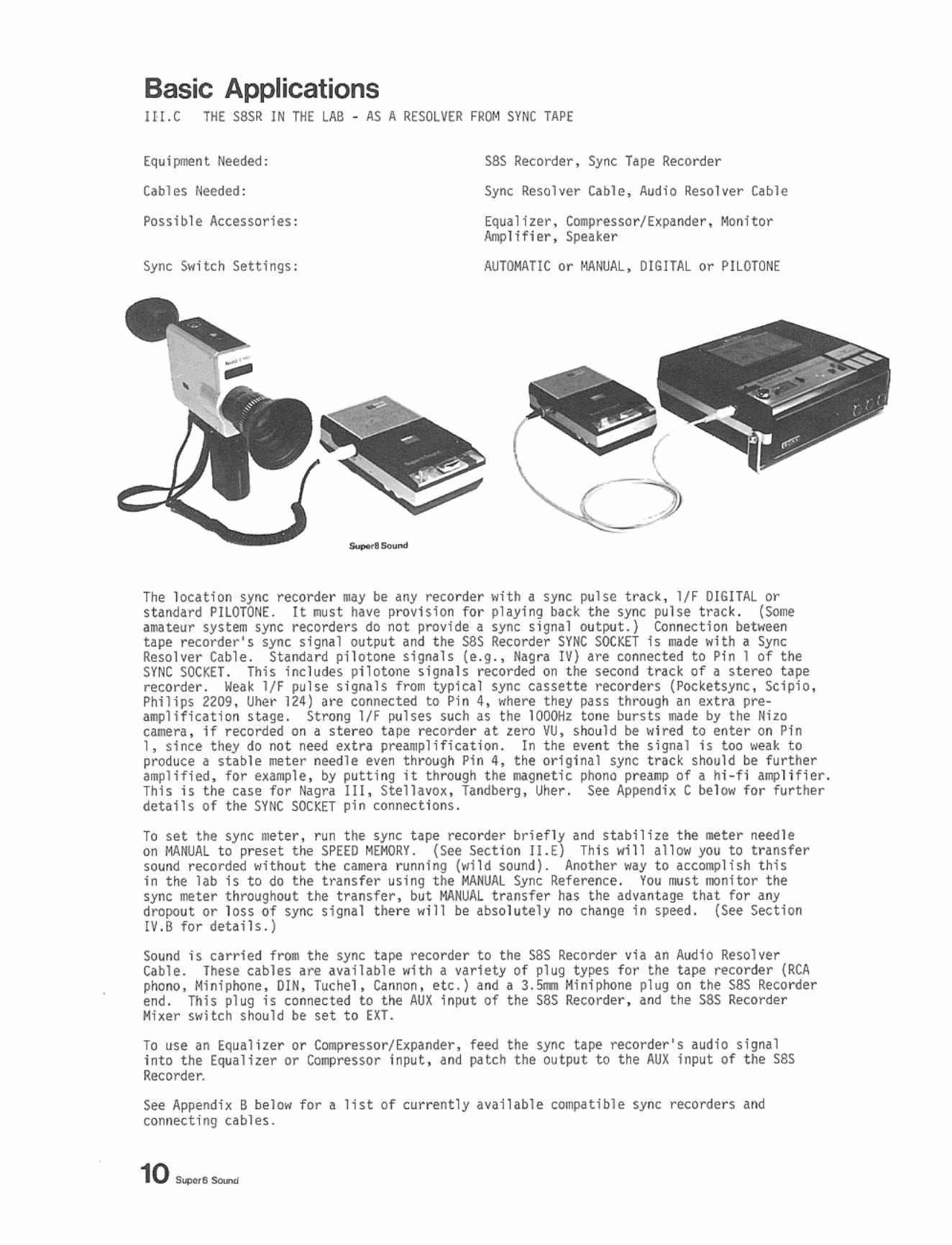
S8S Recorder, Sync Tape Recorder
Sync Resolver Cable, Audio Resolver Cable
Equa 1 i zer, Compresso r/ Expander , Mon; tor Amplifier , Speaker
AUTOMATIC or MANUA L, DIG ITAL or PI LOTONE
The location sync recorder may be any recorder with a sync pulse track, If F OIGITAL or standard PiLOTONE. It must have provision for pl ayi ng back the sync pulse trac k. (Some
j;;.:::':;:;i;:,::sync recorders do not provide a sync signal output.) Connection between sync signal output and t he sas Recorder SYNC SOCKET is mde with a Sync Standard piloton€' signals (e.g ., Nag ra IV) are connected to Pi n 1 of the
incl~des pi l otone ~igna1s recorded on t he ~econd trad of a ~tereo t~pe ~".~. l/F pu l se ~ i 9na l s from typ1cal sync cassette recorders (Poc ketsync , Scipio,
2209 , Uher 124) are connected to Pin 4, where they pass thraugh an extra pre-on stage. Strang l/f pulses such as the 1000Hz tone bursts m de by the Nilo
1f recorded on a stereo t ape recorder at zero VU, should be wired to enter on Pi n t hey do not need extra preamplifintion. In the event the signal is too weak to
; ! ;"i; :st ~ble needle even through Pin 4, the original sync track should be further for by putt ing it t hrough t he lliIgnetic phono preamp of a hi-fi aOllI1fier.
ill , Stellavox, Tandberg , Uher. See Appendix C below for furt her d; •• , . pin connections.
To set t he sync me t er, run t he sync tape reco rder briefly and stabilize the nteter needle on MANUAL to preset the SPEED MEMORY. {See Section lI.E} This will allow you to transfe r sound recorded without t he camera running (wild sound ) . Another way to accomplish this in the lab 1s to do the transfer using the MANUAL Sync Reference. You must monitor t he sync meter throughout the tranSfer, but MANUAL transfer has the advantage that fo r any dropout or loss of sync s l gnal there will be absolutely no change in speed. (See Sect ion IV.B for details . )
Sound is carried from the sync ta~ recorder to the S8S Recorder via an Aud10 Resolve r Cable, These cables are available wHh a varlety of pl ug ty~s for the tape recorder (RCA phono, I'.ini phone, OIN, Tuc hel, Cannon. etc.) and a 3.m Miniphone pl ug on the S8S Recorder end. This pl ug is connected to the AUX input of t he S8S Recorder, and t he S8S Recorder Mixer switch should be set t o EXT.
TO use an £qualizer or Compressor/Expander, feed the sync tape recorder 's audio signal into the Equalizer or Compressor input, and patch t he output to the AU X lnput of the S8S Recorder.
See Appendi x B below for a list of currently avai lable com]1<ltibl e sync recorders and connecti ng cables.
Basic Applications 111.0 THE S8SR IN THE LAB - MAKING A SAFE COpy OF ORIGIML SYNC SOUND
Equipment Needed:
Cables Needed:
Possible Accessories:
Sync Switch Settings:
S8SR, Stereo or 4-channel recorder or a second S8SR QI. a Pilotone Recurner
Sync Resolver Cable, Audio Cable
Equal i zer
AUTil'IATlC, LINE
The Sync Resolver Cable RCRCA will carry a IV 60Hz pi l otone sync S8S Recorder SYNC SOCKET to the sync signal input of "
Pin J of the or to a Front) is
to zero VU . chosen sync channel of a stereo or 4-channel recorder. rec()I111Iended as the sync trac k. The sync channel The SBS Recorder will sync to this recorded fer the sound back to fullcoat. The Audio
of the S8S Recorder (Mini phone plug), and'::::;::;;;i;:i;;;i tt.e tape recorder . Choose an intermediate cont rol, and do not change it during the l evel.
A safe copy ntay be made direc t ly onto fullcoat mg film with two SSS Recorders. Sync them both on AUTOOTlC, LINE, afld connect the r~ONITOR out~t of the original recorder to the AUX input of the copy recorder, using a Miniphone-to-Hiniphone cable.
III.E THE saSR ON THE EDITING BENCH AS A SI)JAWK BOX
Equi~nt Needed :
Cables Needed:
Possible Accessories :
Sync Switch Settings:
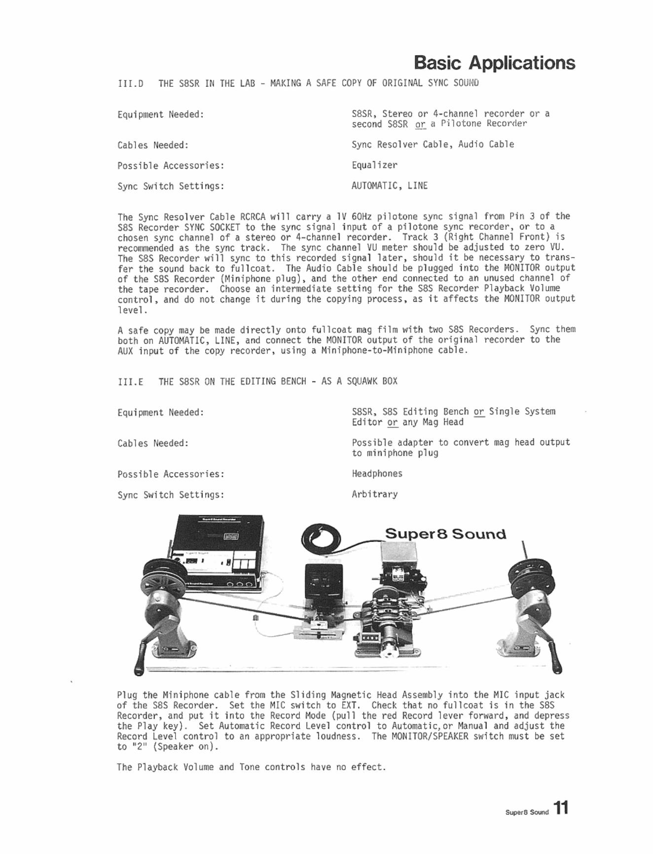
S8SR, sas Editing Bench or Single System Edi tor or any Mag Head -
Possible adapter to con~ert mag head output to mini phone plug
Headphones
Arbitrary
Sound
Plug the Hiniphone cable from the Sliding Magnetic Head. Assembly into the Mle input jack of the SSS Recorder . Set the Mle switch to EXT . Check that no fullcoat is in the S8S Recorder, and put it into the Record Mode (pull t he red Record lever forward, and depress the Play key). Set Aut~tic Record Level control to AutOfllatic,or Manual and adjust the Record Level control to an appropriate loudness . The MONITOR/SPEAKER switc h must be set to "2 " (Speaker on).
The Playback ~ol u me and Tone controls have no effect .
~"Soo..-.d 11
Basic Applications Ill. r IN THE SCREEHltIG R()OH DOUB LE-SYSTEM PROJECTION
Equlpftmt Heeded:
Cables Needed:
Possible Accessor ies:
Sync Switch Setti ngs :
SSSR. Super 8 Sour>d Sync Projector with 1/F Contact Switch, PhotoSUrt or CDfJII"(In Star t BQx
None
htenslon Speaker , Allp l H l er. n.lng Leaders
AUTOWITlC, ~IGITAL
After rushes are synced up on t he Super 8 Sound Editing Bench. they ~y be prtljec t ed In sync. You should prepare sound and picture strands "Hh appropr iate leaders. At a .. inlmu. you need a set Of leader start .... rh (See Appen(lh. E). For double - systl!lll projection with" C~n Start, you shou ld /\ave your picture leader IIiIrked with a crossed fraDe , and a punched ho l e if possible. You r fulleoat mag fl1l1 leader should have a corresponding c ross (no punched hole) on the frame which is "straight acros s" in editorial sync .
for double-systelll projection wltll t ile Super 8 Sound PhotoStart, your picture leader should be Super 8 IIf.gnetic fi l., which 15 "bh.cker" th~n bl~ck leader. PunCh a hole (or sc rape away t he eGU1slon) at the start IIf.rk , and put a cross In the f ra-e at t he sane point as a visual guide. H.l.rk the !lag filn as before with a cross at the corresponding editorial sync frame . You need not worry about "prOjection sync' and the 18 f rame advance wHh regnet ic fil m M t he Super 8 Sound Reco r der.
Your proj ector .... s t be outfitted with a l/F contac t switch and a cable for connection to the sas Recorder Sync Socht. The Super 8 Sound Projector Modification Kit (PKIT) Is ava lhble for this jlUrpose, or you fWy send your projec t or t o Super 8 Sound for n;Jodlflcatlon.
Set up pnljector and S8S Recorder , with t he projector's sync cabl e connected to t he sas Recorder. With Mg filn in the recorder, and picture fll" in a warmed-up projector , turn t he.. both on and set the SPHd Tuning to sL!lbilize tile sync lleter needle . (Section Il.£)
Position the mag fil. star t frarae exact ly at the playback head of the S8S Recorder. Plug the Pho toStart Into the sas Recorder Rerote socket, or plug the S8S Recorder into the Connon Start Box, and t urn tile Box off.
If I,Isi ng a cc.non Start BoK" :,:; ~::~: the picture f iln sta'''i"f,;',i.~me (cross ~nd punched hole) uact ly in the gate of ~~ This can be done into t he lens If tllere is no s t i1\ plCtll re t he prtljector, or lens dnd direc t ly which f rame i If there is no t he projector with t he the
and reposition 'i::;;::": and "hllp on" . Comon Start SDK In sync .
" you throw start and
If ~s i ng tile SSS PhotoStart, press t he sas Recorder phy button , hold t he PhotoStart In front of t ile l ens , dnd turn the projector to "forward " and " I ~np on", When the punched f rame start IM rk passes the ga t e, t he f lash will energize the Pho t oStart , wh ich wil l start the S8S Recorde r through the Remote socket.
In either cue, I_diately check the sync lle te r needle for s t ability and then proceed with the screening.
It Is best if tile f i rst i Nges and sound are from rJa tched projection leaders (e.g . SMPTE Universal Leader and a "beep tone" on corresponding nIIIg filill is the profess ional way, but II bri ef shot of II clapst i ck will dol so that exact sync can be confinne<! at tile OlItset of the screening.
If for some reason sync Is 51 ightly off, some experimentation with llarking the best position on the Super 8 Sound Recorder for the mag fil m start will serle to calibrate tile system exac tly , taking Int o account slight differences between projectors and S8S Recorders , and prOvide reHable and repe.1table sync starts.
Basic Applications
III.G TIlE SlISH IN THE SOUND STUDIO MULTIPLE SUPER 8 SOUMO RECORDERS
Equipment Heeded:
Cables Heeded:
Poss ible Accessories:
Sync Switch Settings:
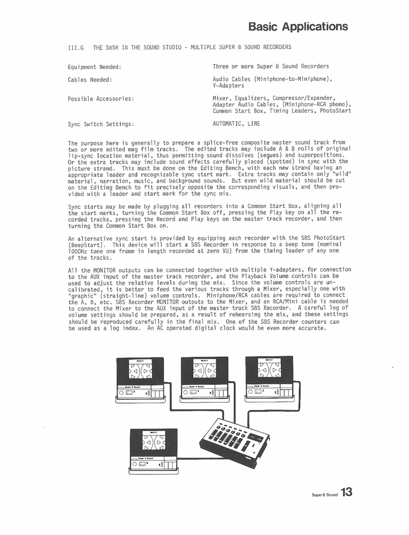
Three or -ore Super 8 Sound Recorders
Audio C~ble s (Htntphone- t o-Hiniphone). V-Adapters
Mixer, Equa l i zers . Compressor/Expander, Adapter Audio C~b l es. (Min i phone- RCA phono), Corooon Start Bo x, Tilling Lnders, PhotoStart
AUTOMATIC. LINE
The pllrpose hen! is generally to pN!pare a sp l ice-free coraposite master sound track f l'Oll two or IOOTt edited mg ( 1111 t rICks. The edited tracks IIa:f Inc luo:le A & 8 rolls of original l1p-syoc locat ion IIIo/Iterill, thus j)t!nlltting sound dlssolves (se9ues) and SUpeT1Xlslt1ons. Or the extra tracks l1li)' illClude sound effects carefully placed (spotted) in sync with the pictuN! strand. This .. st bl done 011 the Editing Bench, with uch _ stra nd lining an appropriate leader and recognizable sync start IIolrk. Extra traCks lI'IIIy contain only ·wlld" ~terial, Mrratlon, music •• rod background soun.ds . But even wlld ..aterlal should be cut on the Editing Bend to f i t precisely opposite the corresponding visuals, and then provided with a leader and sta rt IliJrk for t he sync rRix.
Sync starts lIldy be III/Ide by plugging all recorders into I Cornnon SUrt Box , aligning all t he start marks, turn i ng tM COlll1lOn Star t Box off , pressing the Play key on all the recorded tracks, preSSing the Record and Play keys on t he JIIIster track recorder, and then tu rn ing the C(lfI1IOn Surt Box on.
An al ternative sync Hart is provided by equipping each re<:order with the sas Pho toStart (BeepStar t ) . Th i s device will start a sas Recorder in respOnse to a beep tone (n~inal lOOOKz tone one frllle in length recorded at zero VU) fTOll the tI.lng leader Of anyone of the tracks.
All the HOHITOR outputs can be tOl"lllected t O<)ether >l i th .... 1tlple V-adapters, fo r connection to the AUX input of the IIIJster t ract recorder, and the Playback Volume controls can be used to adjust the relative levels during the .. h. Since the volune controh are uncall brated, it is hetter to feed the various tracks through a Mher, especlall)' one with "graphic· (straight-line) volul!I! controls. Minipllone/RCA cables are required to conne<:t the A, S, etc . sas Recorder i'(lNlTOR outputs to the Mixer, and an RCA/Mlnl cable is needed t o connect the Mixer to the AU X Input of the master t rack SSS Recorder. A careful log of vo l ume setti ngs shoul d be prepared . as a result of rehearsing t he ml~, and these settings Shoul d he reproduced care fully In the fina l mix. One of the S8S Recorder counters can be used as a log In.de~. An AC operated digital clock would he even nore accurate.
Basic Applications III.H THE saSR IH THE SOUND STUDIO· WITH A f OUR-CIlANHEt TAPE RECORDER
Equipment Needed;
Cables Needed:
Possible Accessories:
Sync Switch Settings:
S8SR, Moultitrack hpe Recor<ler .. It II Independent Ch<lnnel Controls (e.g. SONV TCSS4-4S, TC188, TEAt 2340 , 3340). PhotoSLlIrl
Sync Resolver Cable (RCRCA), Aud io Resolver Cables (RCA t o Hinl)
[qua 1 izers, eo.pressor/E~~nder. Hj~er
AUTOMATIC, LI ME (for initial transfer of first sync tnck to four-c ha nnel)
AUTOHATlC, PILOTOME (for,lI other transfers)
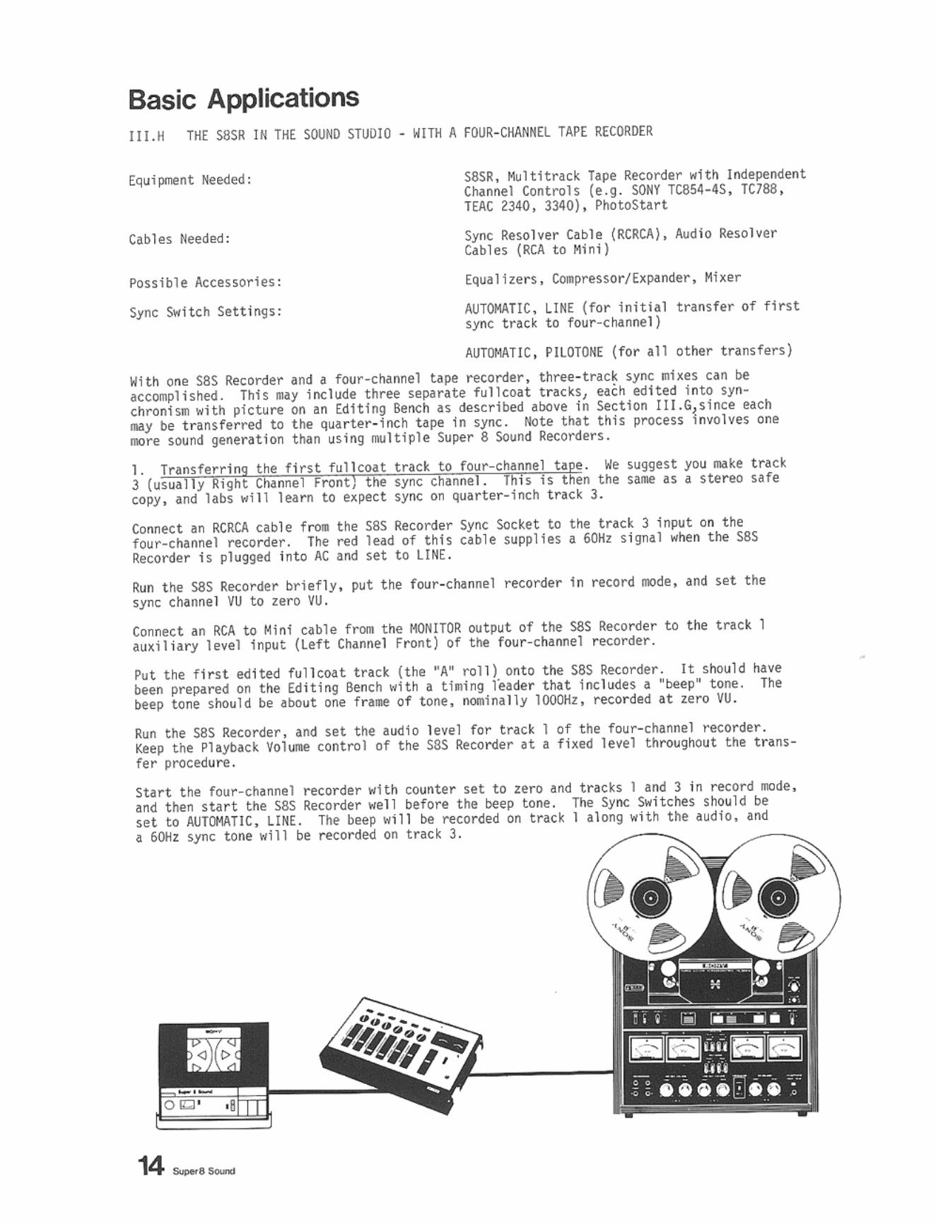
With one sas Recorder and a four-channel tape recorder, three- track sync .. hes can be accompliShed. This Ny include t hree sepnate full toat trac ks, each edited in to syochroniSIl with picture on an Ed1ting Bench as described at>ove in Section IIJ.G,s;nce each lIiIy be t ransfe r red to tile qua r ter- inch tape In sync. Note that this process l nvolvn one oore ~ound generation than u~tng JIlIlttple Super 8 SOund Recorders.
lie suggest you make t rad the same as a stereo safe
trac~ 3.
Connect an RCRCA cable fro. the S8S Recorder Sync SOcket to the track 3 input on the four-chAnnel recorder. The red lead of thl~ cable supplies a 60Hz s i gnal .. hen t ile S8S Recorder is plugged into AC and ~et to LI NE.
Run tile SSS Recorder briefly. put the four -channel recorder in record lIIOde. and SH the sync chlnnel VU to zero vu.
Connect an RCA t o Mini cable fNllJl the I1ONlTOR output of t he sas Recorder to the track 1 au ~iliary level Input (Left Channel Front) of t he four-channel recorder.
Put the f irst edited fullco.!t tract (t he ~A' roll) on to been pre~red on tile Editing Bench .. ith a ll .. lng ruder beep tone should be about one fraill1 of t one, nomina l ly
S8S Recorder. It should hAve Inc llH1es a "beep' tone. The
recorded at zero VU.
Run t he sas Recorder, and set the audio level for tract I of t he four-channel recorder. Ki!ep the Playback Voh_ control of the sas Recorder at a fixed level throughout the t ransfer procedure.
Start the four -channel recorder .. ith counter set to zero and tr~c~s I and 3 in record mde. and t he~ start the S8S Recorder .. el l before t he beep tone. The Sync Switches should be set to AUTCllATlC, LIHE. The beep "ill be reco rded on track 1 al ong .. H h the audio, Ind a 6()1l sync tone .. ill be recorded on trac~ 3.
' .. • roil . . ,. ',
14 __ _
Basic Applications 2a. Transferring the next two ful1coat tracks to four-ch~nnel tape.
Before transferring t he next two tracks , you shou l d check the accuracy of t he whQle set up, including your particular four-channel recorder , your S8S Recorder, and your PhotoStart . To dO t his, you must let the S8S Recorder match its speed to the recorded pi l atone sync signal on track 3 . Connect the bhd lead of the RCRCA cable to the t racK 3 output of the four-channe l recorder. This sends the previously recorded pilotone bac k to the sync input of the S8S Recorder. Change the Sync $\fitch Settings of the S8S Recorde r to AUTOMATIC, PILOTONE. Run both four-channel and sas Recorder briefly to confirm that the track 3 playback level is providing a reasonable sync signal to the S8S Recorder, and t he sync I1Ieter needle is steady.
Now rewind the "A" roll of sound to t he beep-tone start I!Idrk, and align the start Ilark with the pl ayback head. Insert t he PhotoStart in the Remote soc ke t of the S8S Recorder , and connect the "Beep" input of the PhotoStart to the track 1 outpu t of the four-cha nnel recorder . Rewind t he four-channel recorder to just before counter number zero, start the fou r -channel recorder in Playback mode with the volume on track 1 at nonnal level, and depress the Play key of the S8S Recorder (it WQn't run until the beep tone). The beep tone will start the S8S 'Recorder, and the origina l and duplicated sound shoul d play back in precise sync . If there is even a slight difference, repeat the procedure, but with the start m..l.rk offset from the record/playback head as needed to achieve perfect sync. This calibrates the setup for t ransfer of additional track~. You probably need to perform this procedure only onece . From then on, just a lways a li gn start m..l.rks at the recalibrated position you establ i shed, and Photo(Beep)Starh will always be in sync .
You are now ready to transfer a second ("B" roll) fullcoat track, say to track 2 . The setup 15 identical to the chec k procedure above, except now the S8S Recorde r MONITOR output should be patched i nto the four-channe l recorder's track 2 input, and track 2 (Left Channel Rear) of the four-channel recorder should be in record mode. Re peat the Photo(BeepjStart procedure, with the beep tone from track 1 aga i n starting t he S8S Recorder.
A third track can also be transferred ("C" roll). Just patch the MONITOR output into track 4 and engage track 4 i n record mode,
[luring both these transfer s the S8S Recorder is in perfect sync with the original sound because it is servo-controlling its own speed t o IIIdtch the or i ginal sync (track 3).
2b. Dubbing new material onto t he ext ra tracks.
Tr ackS 2 and 4 could of course have been used to lay in new wild IIIiIterial (nar rat i on, music) that did not need to be prechely located rela t ive to the picture . The f ou rchannel reco rder can easily be rolled back again and again to add new sounds precisely opposite origi na l sounds . In this way , unusable lip-sync or i ginal l ines m..l.y be precisely replaced by new lines recorded in the studiO. To achieve perfec t synchronislll with the original , the four -channel recorder Should have "Synchro-track" Or "Simul-sync" capabil i ty, whiCh lleans t he record heads and playbdck heads are "straight across" or "in line". An alternative to "Synchro-track" is to operate t he tape recorder at IS i ps so t he l ag between reco rd head and playback head is unnoticeable .
3. TranSfer (Mix down) back to a composite master fulltoat trad .
The sync wiring setup and Sync Switch Settings are iden tiCdl to section 2a. above . The S8S Recorder is still syncing up to the track 3 or ig inal pilotone. However, now t he output of trac ks 1, 2 , and 4 should be COillbi ned through a Mixer and fed to the AlJX i nput of t he S8S Reco r der . Put a f res h roll of f ullcoat in t he S8S Recorder. Rewind the fo ur cManoel recorder with all channels i n Play mode to j ust before counter number zero . Depre~s the Record and Play keys of the S8S Reco rder . Start the fo ur-channel recorder. The pi lotone signal from track 3 will hold t he fresh fu11co at in perfect sync with the ori gina l edited tracks, and the t hree audio channelS can be ",ixed down to one final sound track.
The beep tone will be transferred to the m..l.ster track. Ta~e the master track to the editing bench and locate t his short beep se9lllent. />lark it with an appropriate crossed frame and punch a start mark hole at the projector sync posltion 18 frames beh ind (c loser to t he tail of the fullcoat) the beep. Thi s pu t s the sound at the standard 18 frame advance position (See Section llI. F) relative to a visual start mark for align ing t he IJIag filll m..l.ster trad in t he S8S [}auble-Band Projector . A pr i nting and protective leader should also be added to the master track (See Ap pendix E) .
Basic Applications I[ L I TIlE SSSR 1M THE SOU ~D STlJ010 SYlt< DUSB1NG AND Ulli REPlACEM(IH
Equipment Neede<J:
Cabl es Needed:
Poss ibl e Accessories;
SyllC Switd Settln~s:
Two or n:> re saSR' $
None
Mi crophone, Mixer. Equ~liler. C~resso rl Expander, Connon Star t BoA or Pho t o(8eep)· Stlrt, Headphones. Stereophone Y-Ad~pter
AUTOMATIC, UNE
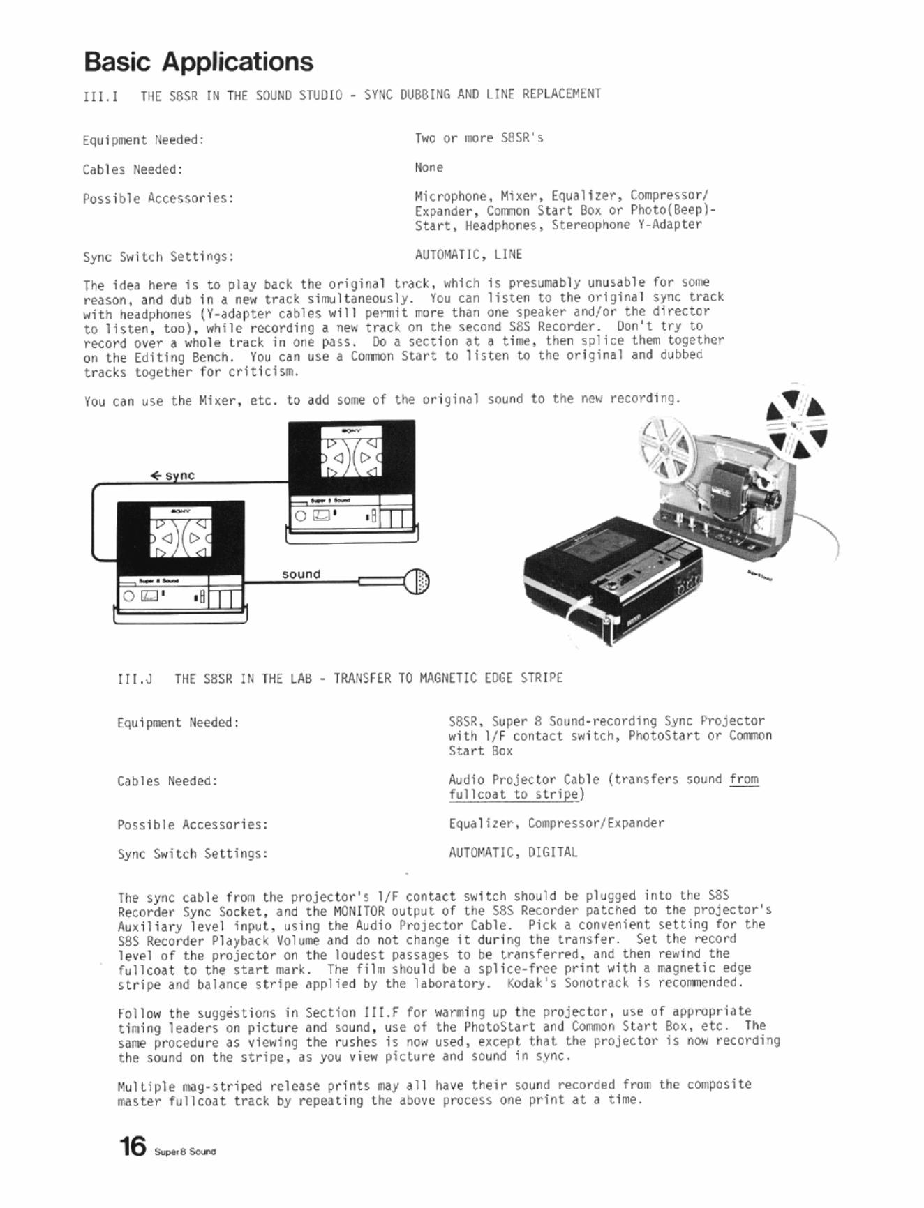
T~ Idea here Is to pia.)' !».ck the origin.l trac~, which t~ preSun/lbly unusable for screason, and dub In a new track sj~lUneollsly . You can listen to the orjgin~l sync track l<1th he~dpho"es (Y-adapUr cables 101 111 permit mo re than one speaker and/or the director to lhten, too), I<Ihlle recording a new trdC~ on the second S8S Recorder. tIon't try to rKord over a whole track in ont pass . Do a section at a tllllt, t hen spllee them together on the Editing Bench. You nn use a COIInJn Start to listen to the ort .. !nal and dubbed tracks toqether for trlt! ch •.
You can u~e tile Mher, etc. to add s~ of the or igiMI sound to tIM! new recording.
!! I. J THE SSSR IN THE tAS - TRANsr(R TO KAGNET!C EDGE STR IPE
[qulc-e<lt Heeded:
C~bles Needed;
Possible Accessori es:
Sync Switch Sellings:
S8SR. Super 8 SOund-recording Sync Projector with IJ F conU ct switth. PhotoStart or ComIOn Start Sex
Audio Projector Cab le (tnnSfers ~ound from fullcoat to stripe)
Equalizer . Comprelsor/ E~pander
AUTorATIC , DIG ITAL
The sync ubiI' frOll lhe projec lor 'S l/F contact switch Should be plugged in lo the SSS Recorder Sync SOcket, and the MONITOR outpu t of the S8S Recorder patched to the projec t or's Auxiliary level inpyt. u5ing the Au dio Projec tor Cable. Pi ck. conveni ent setting for U1e S8S Recorder Playbac k Vo l ume and do not c hange It during t he transfer . Set t he record level of the projector on the loudest PHSlges to be trans ferred . ~nd then re ... lnd the fullcoat to the sU rt .ark. The film should be a splice-free pr int with a 1M9netiC edge stripe and balance s tripe applied by tile laboratory. Kodak's Sonotrad i s recOlll1ll:!nd e.:l .
roll ow the suggestions in Sec t ion II!.F for W4n11i ng ul) t ile I)rojec tor , use of ' wropria te tin ing leadel"S on picture and sound . use of the PhotoSta rt and ton.In Start SOl. et,. The sant' procedure as vi41Wing the ruslles is no ... used. e~,ep t thH the projector is now recordi ng the sound on the stripe, as you Vi41W pic ture dnd sound in sync.
Multiple 11i19-stril)ed release I)rints 1liiy ~11 hdVC their ~oun d recorded fr"Olll the compOsi te IIiIster fulleoat tra,k by repeating the above process one print at d time.
16 ~e_
Basic Applications
III. .. TI;[ saSR III THE LAB - TRANSfERS FRI)! SiNGlE-SYSTEM ORIGlliAl FI LM
Equl~ot Needed:
C~blM Needed:
Possible Accessories:
Sync Switch Settings:
saSR, Super 8 SOl.lnd Sync Pl"{ljector with If f canuet switch
•
Audio Resoh@r Cable (tr~nsfers sound fTOII1 stri!)e to fu11eoat)
Equa 1 i zer, Compressor/Expander, Hum Fi1 t er
AUT~T I C, DIGITAL
The purpose ller" ls to resohe ( t nos t er) t he sOtlnd froll stngle-systeM .... gnetlc striped tn. to fullcoat..ag ril. for double-syste- editing. The pl"Oct<:lure is sl.llar to transfers to str1pe (sec tion III.J) and is also an extension of viewing tilt rushes in sync (Section '".F). The sync ubiI'! frc. till> projector Is still connected to the sas Retol'der Sync SOcket, but oow an Audio Resolver Cable qoes fl"Olll the Prtljec tor 's audio output {tilt spu~er output on len tllM!nsive projeuors, t he a~IHter output (Ion bfotter Nthines). through a filte r or equalizer to the AUl input of the SSS Recor<ler.
RecoNl level on the SSS RecoNler should be set for t he loudest passages to be transfer~d. An equa l izer with 4 sharp 60H! cutoff or a hURl filte r shQl,jld be used. since many Super S sound projector s have a conSiderable 60Hz hum C(lmponent in thetr playbac k cin;uits. 5ync starts are unnecessary if a chpstick has been used. If not, prepa re the fi lm and sound with ttming l eaders to simpllfy later syncing up.
lI!.L THE SSSR IN THE LAB TAANSFERS TO VIDEO
Cables Heeded:
Possible Accnsories:
Sync Swt t ch Settt ngs;
SSSR. TPleelne Projeetor and COlor Video '-ra or I:oda~ Yldeoplayer VP- l with l/F sylM; Ql,jtpul. Vtdeo Recorder or Broadcast Equipment
Audio Cable (usually Mini to RC A). Appropriate Vide<! Cables (VP- l to Video Recorde r . usually SNC)
Eq ualt zer, Compressor/Expander. Video Image Enhanter
AUTOMATIC. lINE (AUTOMATIC. DIGITAL i f IfF sync output)
Oouble- syste. transfers to video provide the hi ghest pOutble sound quality since they bypass the sound-on- stripe SUI,Je.
The ClMftOn Start or PhotoStart procedures have Deen covered tn Sect ton III.F ,nd III.J. Instead of transferring sound to the projector, the Audio '-'ble sl\otlld be connetted frathe MONITOR output of tht SSS Recorder. through an Equaltzer. etc. and into the Audio input of the Video Recorder.
The Ttledne P roj~tor (e.g .• the Kodak TVM100A) han AC sy~chrono ~ s devict . It is therefore capable of high quality double-syst@Ol transfers directly to telcy1sion broadcast cameras. with the composite master ITIIIg film t r~c k on the SSS RecoNle r in AC sync provi ding ~ync \ound .
The Kodak Videophyer Vp·l can be ~sed fo r t ranSfers to video UPt recorders , from half.tnch to two-1nch quad. provtded H is equipped with I l/F sync outP~t (.val1able t TOll Super 8 SOund). Special versions of the Kod.)k Videopl ayer equipped with txternal sta t ion sync wtll be av~ilable for direct t ransfers to television broadClst. for double-sys t etll sound they ftl,jst aho h,ve the I /F sync outPlolt. SilKe the PhotoStart unflOt be used with the Videopl.yer. a short ~P tO1M' segment should be spliced in to the leader for synchroroous surts of the Super 8 Sound Recorder.
IV. Unusual Uses for the Super 8 Sound Recorder
IV.A IUps AMATEUR SPEED
The SUf'I!r 8 Sound R~on:ler can be set to 18fps operation by a djustln~ the Speed Selector Sw Uch. The runni n9 Speed is IlOW 3 tnches per second , and f ide lity is sonewh.H poorer. though superior t o IlIOst Super 8 projectors.
Al 18fps t he SiS Recorder .,1 11 not synchronize to the L1 N{, to CRYSTAL , or to PILOTONf s i gnals . The only setti ngs of the Sync s..ltc~s which dre operative are AUTCflATlC or MANUAL. and OJ(:'lTAL . The principal applications are with C411lt r aS (Sec tion III,A). proj ectors (Secti ons III.F, I1I. J , and !lI.K), and as a ruolYer for sync tapes made on cassette sync reco rders (Scipio, Phl1ips 2209). t ven Bell to H<)W"ell Fl1mosound-8 tapes IM~ be re solved if they are played back on a Sei ple or Philips 2209 . Single- SJlHem EktHound 18fps fil ms may a ho be resolved to full coat for editing (Section I1l.K).
IY.B M.\NlJAL SYNC TRANSfERS
When the S8S Retorder 5y", Switch h set to AUTOMATIC, t he servo·cont rol ci rcuitry descri~ i n Section Il.e aoov! is active and the SSS Recorder's ~peed is determined by the MIIster pulse rate. When the Sy nc Switch h se t to MANUAL, the Recorder' s speed h free. 1M ad· justable by the Speed Tuning kno b. The Sync Meter continues to display sync condition. ~r.litting the user to l1a intain sync by cont inu~l\y adJustin9 the Speed Tuning.
IIhen!ver the 5ync si9nal source i5 errHi c , no isy, or t\as unacceptable breaks in cont inuity , sy", NY be IIIIlnt.lned manually by holding tile sync lifter nee<tle steady anywhere in its range. Tills is acco.pl1shed by very slow and SAlll c ha nges in tile Speed Tuning ~nob pos H ion. lIhen t ne sync s ignal drops out, till! needle wil l drop t o the left hand side o f i ts ran-ge. i)"ri ng th is tillt, dO oot change Speed Tuni ng at all. Once tile sync slgn.ll reappears , thoe needle will jU'llJl ~ck to a new position. Don't attempt to ..ave It to the old posit ion. Just watch it to see if it is drifting. If it 15, s tabiliz~ It wherever it can ~ brought to a stop.
Iv.e US E WITH 16m CAAEAAS, PRf)J(CTORS
S<!veral o f ou r customers have used the S8S Retorder with I. c. O!ras , .. st with pllotone 9'flerators . but SOllIe with a IfF cont"t s.itch inshlled.
Two edltin9 op t ion~ are available. H~ve your l~b prepa re ~ reduct ion work~ri n t of the 16no ori ginal UJ Super 8 fOT editing on a S8S (diting Bench. or have your lab transfer the $ound to 16!lln fulleoal mag fl1m for editin9 on a 16r.m bench or Uble. Simply set the S8S Reco rder to AUTOMATIC, LINE for the t ransfer.
To synchronize an ~d ited Super 8 fulltoat t rack with a 16m ~rojector, siqJly inHall • IfF conuc t switch in tl>e 161m projector (use a Super 8 Sound ProjetUJr J1o.dlflcHlon I: l t).
IV .O USING THE BU ILT·]N l'1!eI/OPHQtf( AS A SLATI NG DEVICE
lIith the cal:l@Ta aimed a t t he t op surface of the S8S Recorder, strHe the silver aT" around the electret condenser .dcrophone with an easily seen object such .s • pencil or pen. The foIi"ophone Selector Switch .... st be ut to foIl X or INTERNAL for thh purpose. The camera opera tor should be able to see the striking objec t clearl y (an inde~ f inger will do i n a pinch) , . nd the sound person should strike the obj ect down and he~ it there. Don' t poll it bac~ up or let i t bounce. 1111 s WOuld confu se t hl"9S u the Editi ng Bench.
Rese t tile Mi crophone Selector t o UTERHAL, aM tile camera operator can swi ng arOUM t o f11 . the sync sce"e. Thls process need not be It all no isy in doc..-entlry Si tua tions.
To indica te t.ke nllrllbi!r s , a slate Should be used (or the sound person can tIold up v.rlovs fi ngers) and the take number can be spoken soft ly into the built·in microphone.
18 _._
IV.E STARTfSTOP OPERAT ION FROM A CAKERA
To ~on tr ol the start/stop of the recorder f roo the camera, an ext ra cable or a car:Jera sync cable with two extra leads is a~aihble {optional extra}. Many Super 8 cameras Mve tape recorder sun/stop jacks Interconnectf!<.i to the c,wlera trig9tr, and this cable can generally be fitt~ with t he appropriate (amer') cOllnection.
CAUTION: Some cameras have their npe recorder SUrt/stop jac~ 9rounde<j to the ca!ll@ra sync socket, and this requires a special cable to avoid a shor t drcuH In the S8S Recorder. The S8S Reco rder sync SOCket is grounded, and the ~(HOTE j ack on the S8S Recorder Is at 12 volts above ground. The ROO1E functions by inte.-cepting t he 12V power supply. If a connection h IIIde fl""Oll the REMOTE jack to the S~NC SOCl([ T, a fuse II/Iy be blown in the S8S Recorder, and unfortulllotely It is very difficult to replace. An IJllproperly .wde start/Hop cable mIIy therefore cause a sJ\ort (I.-cuit between the IlV at the Rn~l1E jack, and tne SYNC SOCl([T. Please only use cables II/Ide by Super 8 Sound.
~te that since 58S RlKorder and cameras gener~lly do not stop dnd star t at the same rates, sync is not gua ra nteed 'rOIl shot to Shot when USing ~ st.rt/stop t~b l e. If you n~d ShOtto -shot sync, f1l_ with a Beaulieu SOO8S or ot her single-system sound ca.er~, and transfer to fullclU.t using the Super 8 Sound Recorder (See Section !ILK above).
IV .F I1ECWHCALlY 1NTERLOCWtG THE SUPER 8 SOOkD RECORDER {wi t h AC synchronous editing tables and other equlpoent)
The Super 8 Sound Recorder can be ~sed for a high- f1delity mechanically- Interlocked mix with pi cture ~y lIIOuntlng two or thret. S8S RlKorders alongside a r.lUltiple-str,nd editing table such as t he Super 8 Research Associates POH-Production Console or the Mt:)! Editing Table. A six-plate table allOO1s two sound strandS {~nd an eight-pla te three sound strands} to be I)iud to another SSS Rec(lrder rurning in.l.e synchronhlll with the editing table.
W1th tne SilS RlKorders locdted u the left side of the table, pull out one o.f the sound stra ndS from the table's supply ree l and thr ead It through a S8S Recorder. Th read the fullcoat ~round an er:lPty supply reel (Ill the S8S Recorder to a~(lid a sha rp bend In the fu llcoat path . Repe~t this procedure with the other sound strands . Each fullcOilt strand sl"""ld al$o be t hr Nded In sync through the editing bench sprockets. leave a few inches of slack between the sas Recorder caps tan and the editing table sprockets. The S8S Recorder "Ill au tomatically ta~e uP the slac~ and establhh the corr ect tension in the fullcon if you folio .. the procl'<.lure below .
S .. itch th~ S8S RlKo rders to AUTOMAlI C, LINE. Plug the S8S Recorders into a COII'.ON STAAT outlet {on the editing table if avalhble}. 1bI c~m start the rec(lnlers ar.d edi t ing uble. Tu .... the SPErO TU!Hr;G controls on the S8S Recorder~ to SLOW , and they will lose franes .. lth respect to the At line sync untIl the shck dislppurs. At t his point the tdbl~ .. nl pull th~ fullco~t along In AC sync , and t he SYNC METER needle .. 111 stabilize . Adjusting t he SPEED CONTROL at this point "ill ch.!nge the SYNC METER needle position and afhct the tenSion in the fullcOH. Y(lU can set it at a desirable lev ~1.
If you stop the editing uble, the S8S Reco rders will all stop , producing I SIIall amunt of slack ag~In. Upon restart ing. the slaCk .. 111 diuwear and the variouS strands will all be back In sync ,
IV.G TRANSFERRING MORE THAll 19 "INurES Of MAli FIU1
Once you h~ye edited I Illig fil_ trac~ thU is 20 _Inutes or longer, you IlIUst do sync transfers in separate se<)flents short enough to fit on a S· reel. An alternHi ve suggested by the SutJl,!r 8 Work shop In Cambridge is to use another tape recurder with la rge r ree l capacity for t he u~e-up and supply reels, "lt~ t he S8S R~corder's capstan drive and sync pho t osensor assembly providing the basle sync control.
•
Appendices
APPENU !X A. LIST OF COMPAT!6bE SYNC CAMERAS
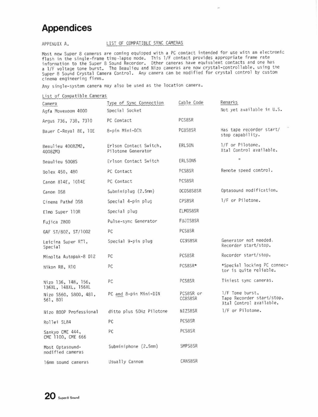
Host new Super 8 Clllltrl$ are COOling equipped with . PC cont.lct in tend~ for use witil an electronic flas n in tile singl e ·fraM t ille-l apse lIOde . Tilts IfF contac t provi des .ppropri,)te fnlle rHe i nforma tion to tile Super 8 Sound Rfiorder . Othe r ca:neru have pquivalent conucts an.s one l>in a 1/f Yoltage tone OOrst. The Seau li et.l and Hila ,_ra s I re now crys tal -controll abl e, using toe 5uper 8 Sound Crystal C..e ra Control. AfIY calilf'ra can be mQdi f ied for c rysta l control by custon ci nema engi neering flnns .
Aroy stngle- sys ten camera may also be used as t he locati on canera .
List of CO!!!pci t ible (anern
Call1e r a Type of Syrw; Conne< t lon
Agf. Hovexoo. 4000
Argus 736 . n8 . 731 0
Bauer ( -Royal 8E , IDE
Beaulieu 4008lM2. 4008"'3
Beaulieu 5008S
Bole. 4W , 480
Onon 814( , I014E
Onon osa
Elro Super IIOR
f uj ic' Z800
GAf ST/SOl. 5T/l002
lei cl na Super RTl , Speci al
"i nolt. "u topa~-8 012
!tikon 118 . RIO
Mizo 136 , 148 , 156 , 136Xl , 148Xl , 156XL
Ni l O 5560 , saoo , 481, 561. SOl
Rol let SUl4
San~yo CH( 44~ ,
CH( 1100 . DME 666
Most Optaso"rldr.ldlfiecl c.arre ras
16rrln sourld c ... eras
20 s-,_
Sj)«ial Socket
PC Contac t
S_pin Mi ni -D IN
Erhon Con tact Switch, Pilotone GenerHor
Erl son Contact Switch
PC Con tact
PC Conu ct
Sulxnlnipl ug (2 ,Snn )
Speci al 4-pin plu9
Specia l pl ug
Pulse- sync Generator
PC
Spec ial 9-pi n pl ug
PC
PC and S_pt n !>llnt - oIt!
ditto plus SOliz Pllotone
PC
PC
IJsua Ily Cannon
""ble Code
PCS8SR
PC8SSSR
EIIlSO!l
ERl SON5
PCSSSR
PCsaSR
OCOSSS8SR
CPSeSR
EV'.oSSSR
f UJISSSR
PCsaSR
CC9seSR
PCS8SR
PCS8SR or ccaseS!!
NIZS8SR
PCS8SR
PCS8SR
SMPS8SR
CAtlS8SR
llot yet ava il able I n IJ . S.
Has u pe recorder startl s top c.pability .
I f f or Pilotonc . Hal Control available .
•
R~te speed contNlI .
Optasound ~d i f iCltion .
IfF or Pilotone.
Generator not needed . Recorder st ar t /stop .
Recorder start/stop .
' Spec lal locki ng PC connec to r h "utte rella ~le .
Tiniest sync cameras .
IfF Tont' burst , h pe Recorder s tar t/s top . H . I Con tro l ayllll~le .
I fF or Pilotone .
APPE NOiX 8. LIST Of CO~PATIBLE SYNC RECORDERS
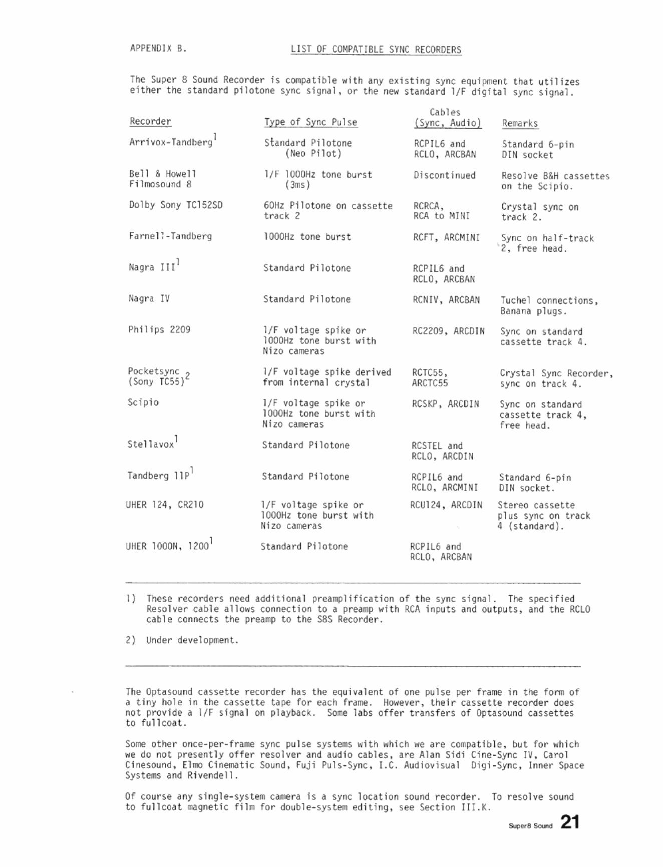
The Super 8 Sound Recorder h cOOIpatible "ith any existing sync equipment that ytili zes either the standaN! pilotone sync s!gn~l, or t he new s t andard IfF digital sync sigMI .
Recorder
Arrivax-Tandberg l
Bel l & HO"oIell Fi lmasound 8
Do l by Sony TCI52S0
Phil! ps 2209
Pocketsync 2 (Sony TC55)
Sc i pio
Stel1avo~1
Tandberg ll pl
UHER 124, CR210
UI1( R lOOON , 12001
Type of Sync Pulse
standard Pilotone (Neo Pilot)
IfF 1000Hz t one burst (J:"IIs)
60Hz Pi I otone on cassette track 2
1000Hz tone burst
Sta ndard Pi lotone
Standard Pi l otone
IfF vol tage spiKe or 1000Hz tone burst "Ith Nizo cameras
IfF yoltage spike derived from internal crystal
I/F voltage spi ke or 1000Hz tone burst "i th Nizo cameras
StandaN! Pilotone
Standard Pl1otone
IfF vo l tage spike or 1000Hz tone burst "ith Nizo cameras
Standard Pilotone
Cables (Sym;, Audio)
RCPIl6 and RCLO , ARCBAN
Oi scant inued
RCRCA, RCA to MJlII
RCFT, ARCMINI
RCPIL6 and RCLO, ARCBAN
RCNIV , ARCBAN
Rema r ks
Standard 6- pin OIN soc ~et
Resol ve 8&H cassettes on the Scipio .
Crystal sync on track 2.
Sync on half- tr aC k 2 , free head.
luchel connections, Banana pl ugs.
RC2209. ARCOIN Sync on standnd cassette track 4 .
RCTC55, ARCTC55
RCSKP, MeD IN
RCSTEL and RCLO, ARCOtN
RCPIL6 and RCLO, ARCMtNI
RCUl24, ARCOtN
RCPIL6 and RCLO, ARCBA N
Crystal Sync Recorder, sync on track 4 .
Sync on standa rd cassette track 4, free head.
Standard 6-pin OIN SOcket.
St ereo cassette plus sync on t rack 4 (standard) .
I } These recorders need additional preamplification of the sync signa l. The specified Resolver c~ble allo"s connection to a preamp "Hh RCA inputs and ou t Pyts, and t he RCLO cab l e connec ts t he preamp to t he S8S Recorder .
2) Unde r devel oprr.ent.
The Optasound cassette recorder has the equivalent of one pulse per frame in t he f orm of a tiny hole in the cassette tape for each f rame. Ho"eve r, their cassette recorde r does no t provide a IfF signal on pl ayback . Sorne labS offer transfe r s of Optasoynd cassettes to fullcoat .
Some other once-per- frame sync pul se systems "ith " hich we are compatible, but for whi ch " e do not presently offer resolver and aud io cables, are Al an Si di Ci ne-Sync IV, Ca rol Ci nesound, El mo Cinematic Sound, Fuji Puls-Sync, I.C . Audiovisya l Oig i-Sync, Inner Space Sys tems and Rivende I I .
Of course any si ngle-system came ra is a sync location sound recorder. To resolve sound to fu ll coat rmgnetic f i lm fOr doubl e -sys t em editing, see Section tll.k. _1_ 21
Appendices
APP[NDIX C. SYNC SOCkET SCHEMATIC DIAGRAM
LO'~ LEVEL SYNC INPUT -___ _
HIGH LEVEL SYI/e !NPl/T----
GRWHD
o 0' J
9 ? ______ SERVO· CONTROL S I G~lAl OIJTPlJT
o PILOTOtlE SYNC QHPUr J '-...... ('IOtIen r eeor der swit(;ht<l to LINE
-.............. ~nd plugged IntG At:. OII t let}
'-_/ l/f SWITCH IN PUT (when recorder switche<l t o DIG ITAL)
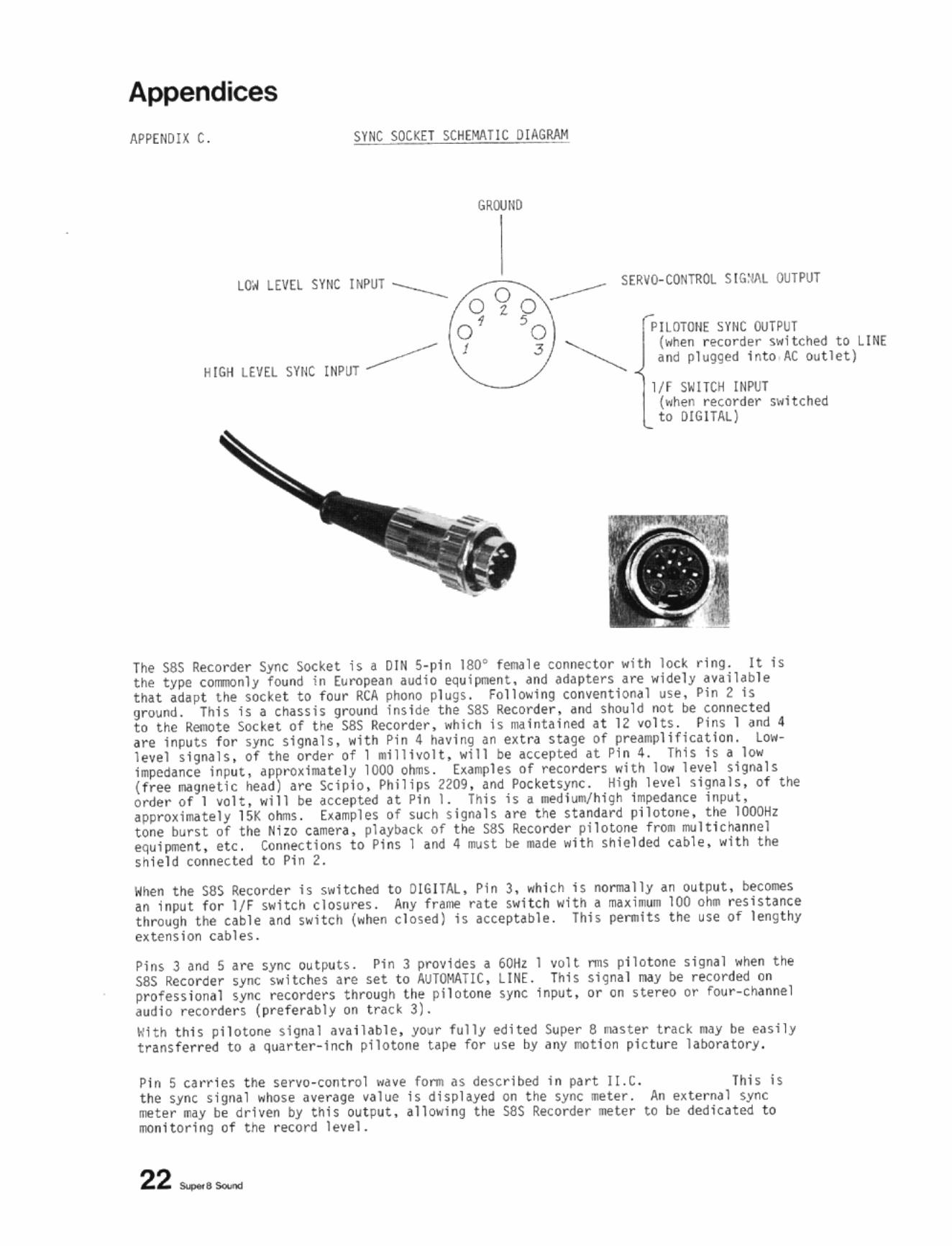
The sas Recorder Sync Socket is a DIN S·p1 " 180· fe.llll le connec tor with lock ring. It is the type cOlTlOOnl~ found in European audio equipl':lf'n t , and adapters are widely avall ab le thH adapt the Socket to four RCA phono plugs. Fol100..\ng con~entlonal use, Pin 2 Is 'Jround. Thh 1$ a chassis gl'{Jijnd Ins ide the sas Recorde r . 6nd Should not be connKted to the Remote SOcket of the s.as Recorder, _hich Is maintained 4t 12 'I1) l t5. Pins 1 ,00 4 <lre Inputs for sync signa ls, with Pin 4 having an e~tra sUS!! of preMlpllfication. lowlevel signa ls. of th orde~ of 1 .illivol t, will be .ccepted at Pin 4. This is') low Impedance inpuL appro~lmately 1000 ohms. h~TIlples of recorder s with low level signals (free magnet ic head) are Sci pio , Philips 2209 , and Pocketsync . High level slgMls, of t he order of 1 volt , will be accepte4 at Pin 1. This is a IledIurn/higl1 Im~dance i!lpul, .pp!"l)~ ioaately 15K olns . v.mples of such signa ls are the s tandard pilotone , tile 1000Hz tone burst of the Hi zo clmera, pl <lYb.tck of the S8S Recorder pilotone fM:* ftllt lclwinnel equ lpg.ent, etc. Connections to Pins I llid 4 Illst he .ade with shlel de4 cable. with the shie ld connected to Pin 2.
When the S8S Reco rder is switc hed to DIGITAL, Pin 3, "hl ch is normally an output. becCMneS an inpu t for If f switch closures. Any frame rate switch with a maxin.n 100 ohM reSista nce through t he uble and switch (when closed) h acceptable. This pe.-.lh the use of lengthy extension c ables.
Pins J and 5 are sync out~ts. Pi n 3 prOvides a 60tlz I volt 1111$ pl1otone signal .. hen the S8S Recorder sync swHches are set to AUTOMATIC, LINE. This signal may be recorded on professional sync recorders thrllugh th" pllotone sync Input, or on stereo or four-Channel audio recorden ( prefer~bly on track 3).
With thi s pllotone signal av~ l l ~ble . YOllr fully !'dit!'d So.Iper 8 nIIster t rack !My be e~ 5 ; ly transferr ed to a quar ter- InCh pilotone Upe fo r use by any IIDtion picture laboratory.
Pin 5 carr1es t he 5ervo·CO!l t rol wave fol"'Jl as de~crlbed in part II.C. This is the sync signl1 .. hose ave rage ~alue Is displayed on the sync ....,ter. An e~terna1 sync _ter .... y be driven by this output •• 1Iowing the S8S Recorder litte r to be de<licHed to monitoring of tne record level.
APPENOIX O. STANMRO TRAC K POSITIONS ON SUPER 8 FULLCOAT I'.AG FILM
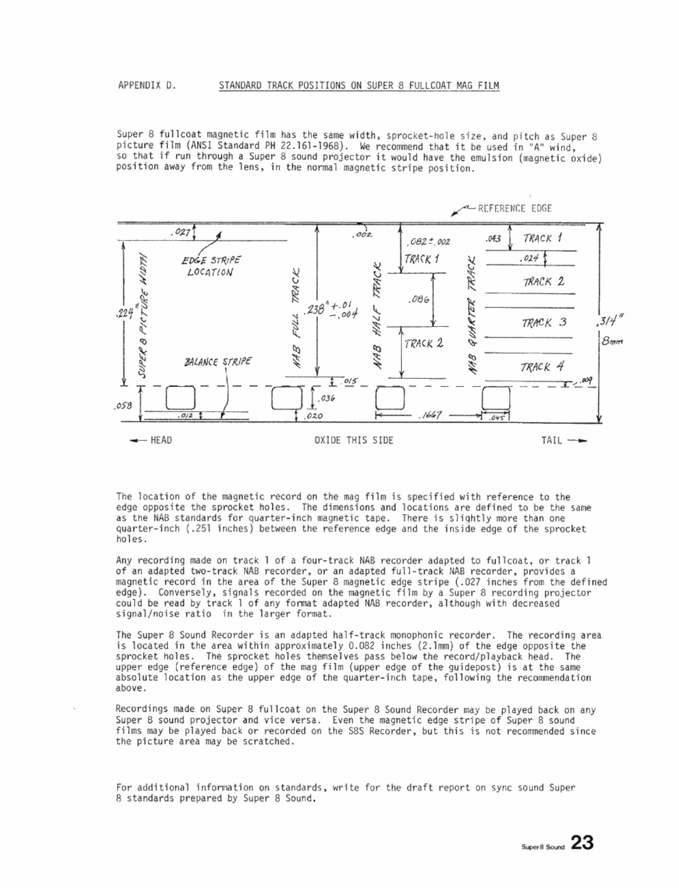
Super S fullcoat ma,gne t ic film has the same width, sprocket- hole size, and pitch as S~per 8 picture film {ANSI Standard PH 22 .161-196S}. We recol!lllend that it be used in "An wind so t hat if run throu9h a Super 8 sound projector it .. ould have t he emulsion (.:aglleti c ~xide) position away from the lens, in t he normal magnetic stripe position .
. c.z';'f I • COl. .... fR~CK ( 082:! c:tI11
EZTR.II'C
.
~ Tf(ArK f ~ . 011
• LOCIlTIOI.j " ~-~ " v
~ ~IICK 1
~ ~ .'" ~ .JZ1(~ .238'+.011 ,
" -. ()() , T!{ACK 3 ,
~ ;: ~ , • 11?1\C.t: 2 '" ~
, ~ MLAJJa sr,;fe , ~ • ~ ~ 7/(IICK 4
'j
'" ~ _ ~ ~ -:..;.16¥ - - - - - - - - - - - -o ~ HEAO OXIDE THIS SlOE TAIL -
The location of t he III/Ignetic record on t he mag film is specified wi th reference to the edge opposite the sprocket holes. The dimensions and locations are de f ined to be the sane as the NAB standards for q~arter -i nch magnetic upe. There is sliqhtly mo re than one qua r te r-i nch (.251 Inches} between t he reference edge and the inside edge of the sproc ke t holes.
Any recording made on t rack 1 of a four - track NAB recorde r adapted to fullcOdt, or trdCk I
.'
of an adapted two-t rack IiAB recorder, or an adapted full-t rack NAB recorder , provides a III/Ignetic record i n the dru of the Super 8 magnet ic e<1ge stripe (.027 inches from the defined edge). Conversely, signals retarded on the III/Ignetic fjllll by a Super 8 recording projector cou l d be read by t rack 1 of any fOf'll\llt adapted NAB recorder, although .. ith decreased si gnal/noise ratio in the larger 'o'"""'t .
The Super 8 Sound Recorder is an ~dapted ha l f-track monopoonic reco rder. The recor ding area is located in the a rea within appro~illl/ltely 0.082 inc hes (2.1rl1ll} of the edge opposite the sprocket holes. The sprocket holes themselves pass below the recor<1/playback head . The upper edge (refe rence edge) of the mag film (upper edge of the gu i depost) is at the same absolute l ocation as the upper edge of the quarter-inch tape, following the recorrmendation above .
Recordings made on Super 8 fullcoat on the Super 8 Sound Recorde r Oldy be played back on any Super S sound projector and vice versa. Even the magnetic edge s tri pe of Super 8 sound films may be played bac k or recorded on the S8S Recorder, bu t this is no t recolflJlended since t he picture area may be scratched.
For additional lnfOlTliltlon on s t andards. write for the draft report on sync sound Super f\ standards prepared by Super S Sound .
, , ,
F.~·' · ,~-~, U.·.,,·
Appendices
APPENDIX E. LEADERS AND LEADER START KARKS
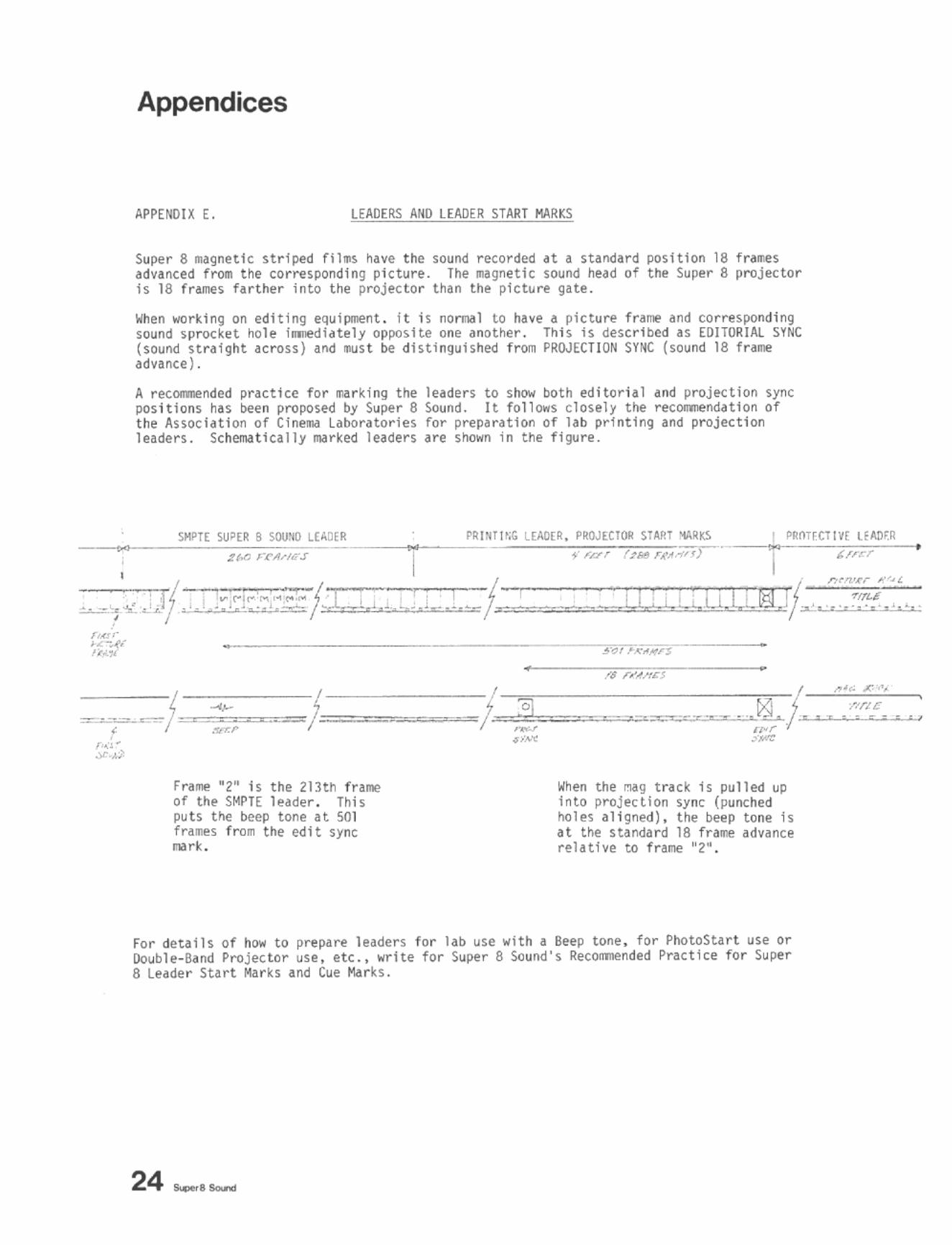
Super 8 magnetic striped fillll~ have the sound recorded at a standard position 18 frarr.es advanced from the corresponding picture. The magnetic sound head of the Super 8 projector is 18 frames farther into the projector than the picture gate.
When working on editing equipment. it is nOrm/ll to have a picture frame and corresfIOnding sound sprocket hole ilmlediately opposite one another. This Is described as EOITORIAL S¥NC (sound straight acrass) and must be distinguished from PROJECTION SYNC (sound 18 f r ame advance) .
A reconmended pNctice fo r rna rki"g the leaders to show bo t h editorial and projection sync positions has been proposed by Super 8 Sound. It fol 10 .. 5 closely the recOImJendatlon of the Association of ClnelM laboratories for prep~ration Of lab printing and projection leaders. Schemat ically IMrked leaders are shown in the figure.
___ "., c""""""""'~'"' ",""~",,._. I ~~"or
• : . ,
,
~ ! '0] ~
~-,- ~f;;::;;~-:;:::, .=:j{~== . . ., ",,' .;r ~)
Frame "2" 1s the 213th frame of the SMPTE leader . This puts the beep tone at 501 frames from the edit sync n/lrko
~,,,,,,,
IoIhen the mag trac~ is pulled UP into projection sync (punched holes aligned), the beep tone is at the standard 18 frame advance relathe to frame "2",
For deUils of how to prepa~ leaders for lab use with a Beep tone. for PhotoStart use or [louble-Band Projector use, etc., write for Super 8 Sound's Reconmended Practice for Super 8 Leader Start Marks and Cue Marks .
•
APPEtiDU F. TROUBLE-SHOOTING CHEC K LIST I SER~ICE PROCEDURE
If you are If you a~ you ha~e
and leave dear up numbe r ,
below.
I
TROUBLE-SHOOTING CHART (WITHOUT TAKING THE saSR APART)
IF NO SYNC
Needle sw;n9S back and forth rapidly, cannot be stabilized with SPEED TUNING control
Needle IS not affe cted by SPEED TUNl~G con t rol
Needle will approxl"",te ly stabi lize , but does not remain steady
Needle Hays t;';;,. signals from "
side (No photosensor holes)
Needle ~Uys to left side (no sync reference) -on LINE
-on CRYSTAL
-on DI(;ITAL OR PI LOTO~E
IF INTERMITTENT SYNC
On OI(;ITAL - while RESOLVIN(; fr~ casse t te tape original
On DIGITAL - \;ith camera
On LI NE
On CRYSTAL
STEPS TO CHECK
Check whether SPEED SELECTOR SWITCH on wrong speed, o r Sync Switch In wrong mode (if DIGITAL . try PILIHONE. and vice versa).
Check that SPEED TUNING switch is ON .
Sync Switch on MANUAL. t r y AUTOfoIA TIC.
CMck that JIIIIgnetlc film Is threaded pro~rly (sprocket i'Ioles down, o ~i de t"",ani head) - and that sprocket holes ~re passing through photosensor assemb ly.
Check that AC cor d is plugged in fin1l ly - Neon light should ~ppe~r in center of meter.
Try stoppi ng ~nd star ting machine.
Check that sync cables are tight. Check for faulty cable.
Cassette sync track may hHe dropouts. S\;itch to MANUAL for transferri ng those se.:tions with poo r sync track.
Check cable - especially PC contact. It is best to t ighten PC connector occa$ion~l1y with pliers 6nd bend t he center pin slightly to\;ard the outer ring. Al ways gaffer tape the cable during filming.
Ched ti ghtness of AC line cord in socket.
Check that III(Ig fil m is threaded proper l y into guideposts.
s..-e_ 25
Appendices APPENDIX G.
SYNC SECTION
Sync Circuit ElKtron1cs
Crystal Speed Accuracy
Sync (1 rcui t Inputs
Sync Circuit Outputs
Sync Functi(N1 Switches .1Id Controls
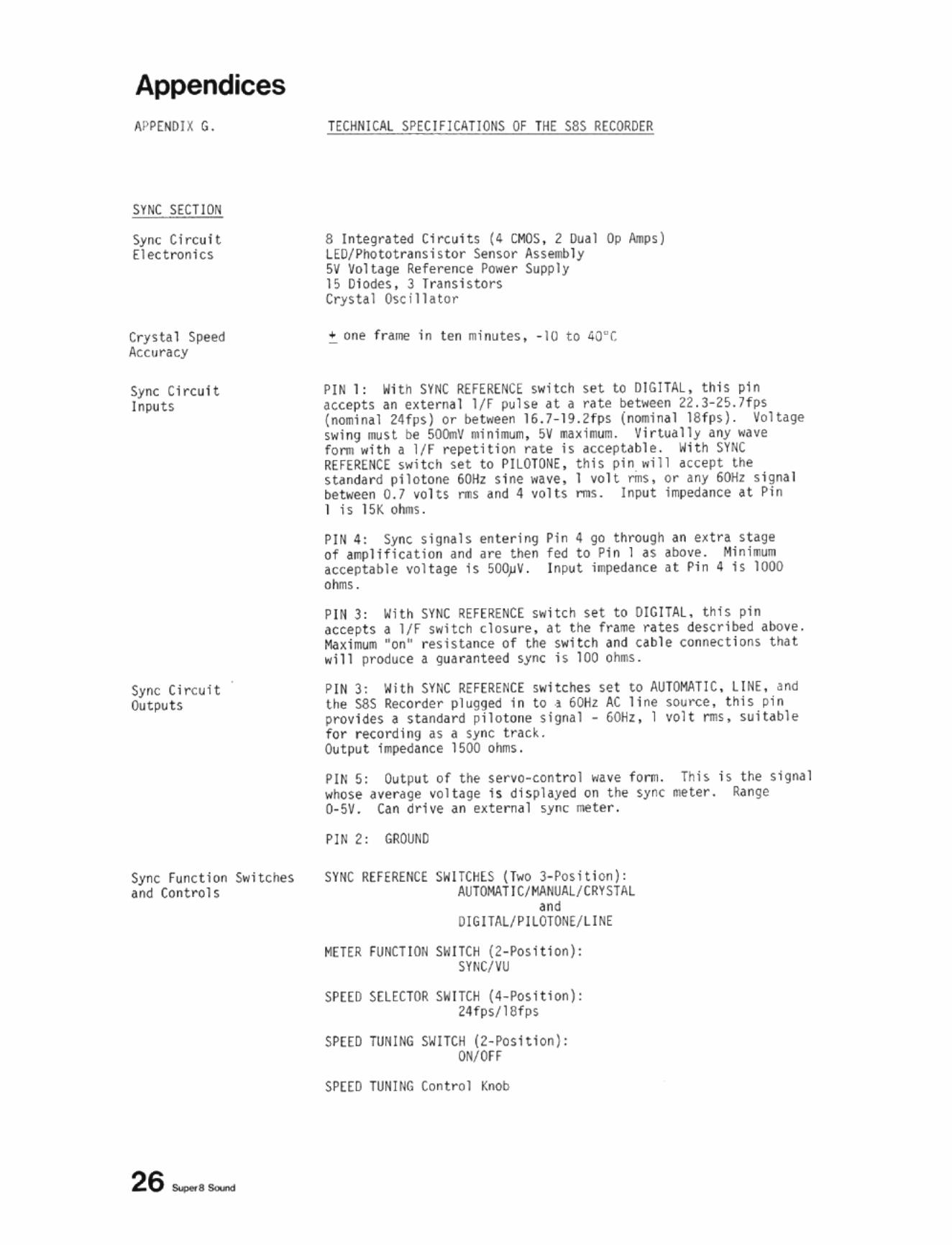
TECHN1U,L SPECIFICATIONS OF THE sas RECORDER
8 Integrated Circuits (4 CMOS , 2 Dual Op Allps) LEOfPhototransistor Sensor Assembly sv Voltage RefererH;e Power Supply IS 0l Gdes. 3 Transistors CrystaIOscf11ator
.. one frame in ten minutes, -10 to 40"[
PIN 1: Witn SYNC REFERENCE switch set to DIGITAL , this pin accepts an uter ... 1 Iff pulse n" ratl! between 22.3-25.11115 (lIOIIinal 24fp5) or b@ tween 16.7-19.2rps (nc.inal 18tps). Volta9l! swing .ust be S(lQnV .Inl_. SV .uilDUl:!. Vi rtually any wave for. with" IfF repetition rHe Is acceptable. With SYNC REFERENCE switch set to PILOTI)NE, this pin "i ll accept the shndard pllotone 60Hz sine wave. 1 volt ms, or any 60Hz signa l between 0.7 volts rIIS and 4 volts rms. Input impedance at Pin I is 15K oh.u.
PIN 4 : Syn~ signals enteriog of aqllificat ion and are then acceptable volt,ge Is 500j.1V. ohms.
Pin 4 go through an e~tra st.ge fed to Pin I as above. Min in. InpUt i~ance a t Pin 4 Is 1000
PIN 3: With SYNC REFERENCE switch set to OIGITAL. this pin accepts a I/F switch closure, at the tra'J\e ntes described above . MIIxi~1II ·on" resistance of the switch and cable conntctlons tha t will produce a guaranteed sync is 100 ohms .
PIN 3: With SY~C REFERENCE swit~hes se t to AUl(lI"lATlC, LINE. and the sas Recorder plugg!!d i n to ,I 60t!z AC line SlHIl"Ce, tllis pin provides I standard pilotolle sh}n,1 • 6Otiz, 1 vplt I'IIS. suit<lble for rfl:ording n a sync track . Output i.pe1Iance 1500 otJns.
PIN 5: Output of tile se rvo·control wave tonn. whose average volhge is disphyed on t he sync 0-5V. Can drtve an external sync I1II!te r.
PIN 2: GROUhD
SYNC REH R£NCE SWITCHES (Two l - Posltton): AUlOKATI C/I'IANUAL/CRYSTAl
'"' OIGITAlf PllOTONt/ lIN(
METER FUNCTION SW ITCH (2-Posi t ton): SY~C/VU
SPEED SELECTOR SWITCH (4-PosHion): 24fps/lBfps
SPEED TUNING SIiITCH (Z- PosHlon): ON/OH
SPEED lUMINa Con trOl Knob
Thh is the signal meter. Ra nge
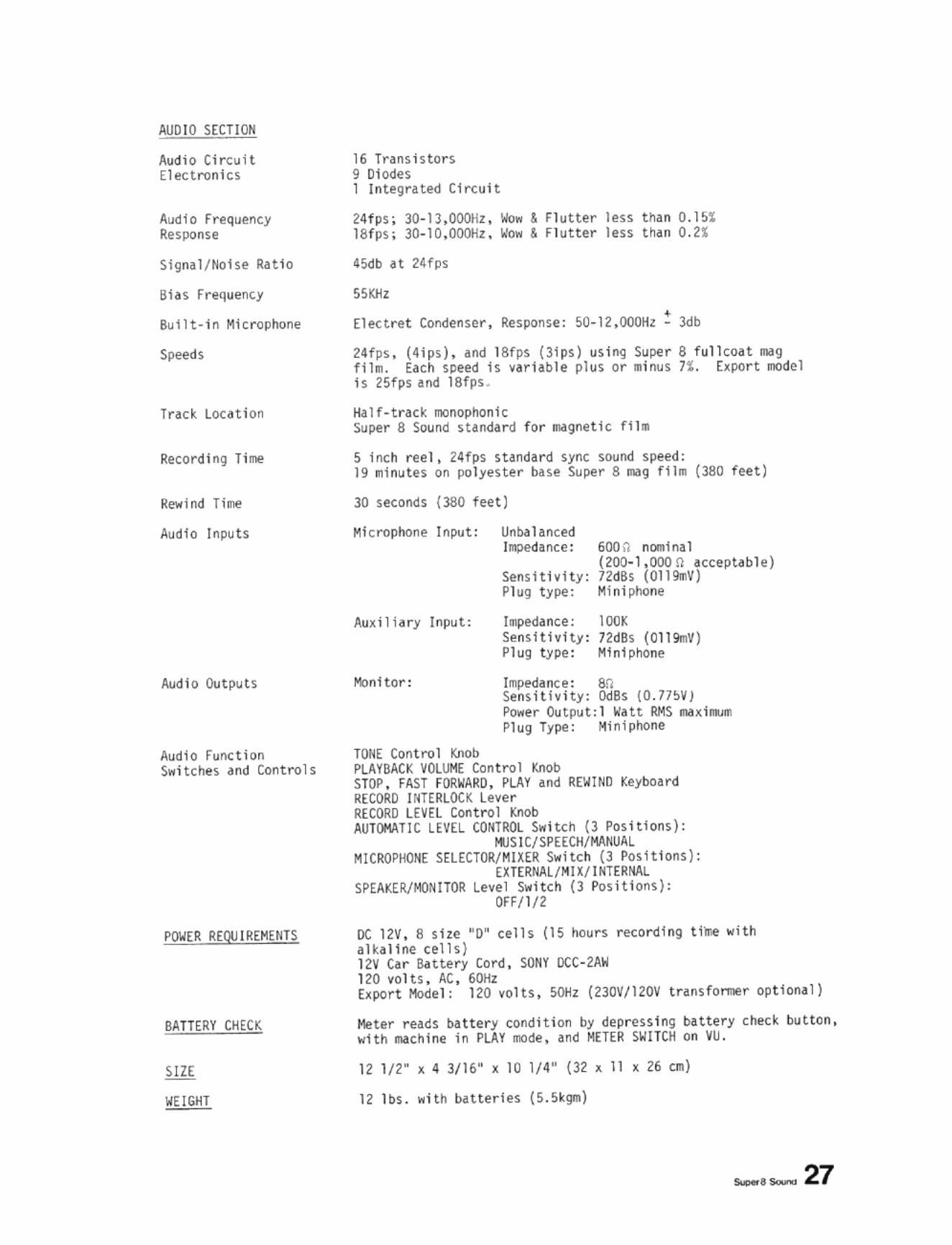
AUDIO SECTION
AudiO Ci r cu it Electn;miC5
Audio Frequency Response
Signal / Hoi se Rat i o
Bi as Frequenty
Built-In Mi c ro ~hone
Speeds
Track LOutlon
Recording Ti llie
Rewind Tlme
Audio Inputs
Audio Outpu t s
AudiO F",lI(tion Switches and COnt rols
POWER REQU IREMENTS
BATTER Y CHECK
SIZE
WEIGHT
16 Transistors 9 Olodes I Integrated Circuit
24fps; 18fps ;
45db at 24f~s
55KHz
Wow '" Flutter less t han O.ISS WoI! '" f l utte r Ins t han 0.21
Elect r e t • Condenser, Response: SO-12 ,OOOHz - 3db
24fps, (4Ips). and ISfps (lIps) using Super S full coat Ng tilln. Each speed is varhble plus or . i nus 71 . [~por t InOdel Is 2Sfps aM 18f ps .
Half·trac~ InOnophonlc SuPfr S Sound s tandard for Ngnetlc f U ll
5 Inch ree l, 24fps standar d sync souM speed: 19 R11nutes on polyester base Super S mag film ClllO feet)
30 seconds (3l!0 feet)
Microphone InP<lt:
Aux ilh ry Input:
Itlnltor:
WHRLOCK RECORD LEVEL AUTOMAT IC LEVEL
MICROPHONE
SPEAKER/MONI TOR
Unbalanced la.ped a II( e :
Sensitivity: Pl ug type:
hlpe<lance: Senslth1ty: Plug Gpe:
600 " nOllllnal (200-1 ,000 0 acceptable) 72dBs (Oll9r.V) Mini~ne
H'" 12dBs (Ol19rnV) Miniphone
ImpNIall(e: an Sensi t iv ity: OdBs (O .n!>v) Power Output:l lIatt RMS ll,ul_ Plug Type: Mlni phone
""b PLAY and R(IoIIND Keyboa r d
thinS):
oc 12V , S she "D" cells (1S ~un recording ti'l!e with alka l ine tells) 12V Ca r B.ttery Cord , SONY OCC ·2AW 120 ~olt $ , AC, 60Hz Export Hodel: 120 ~olts, 50Hz (23DV1l20V transrO l'l'lle r optiona l l
Meter reads battery condition by depr essing b-I.ttery check button, with INthlne In PLAY IIOde , .nd M(lER SW IT ClI on VU.
12 I n" ~ 4 3/16" x 10 1/4" (32 ). 11 ~ 26 til)
12 lbS ... lth biltterles (5.5k9ll'l
,..,_ 27
,. SuperS Souna Recorder o
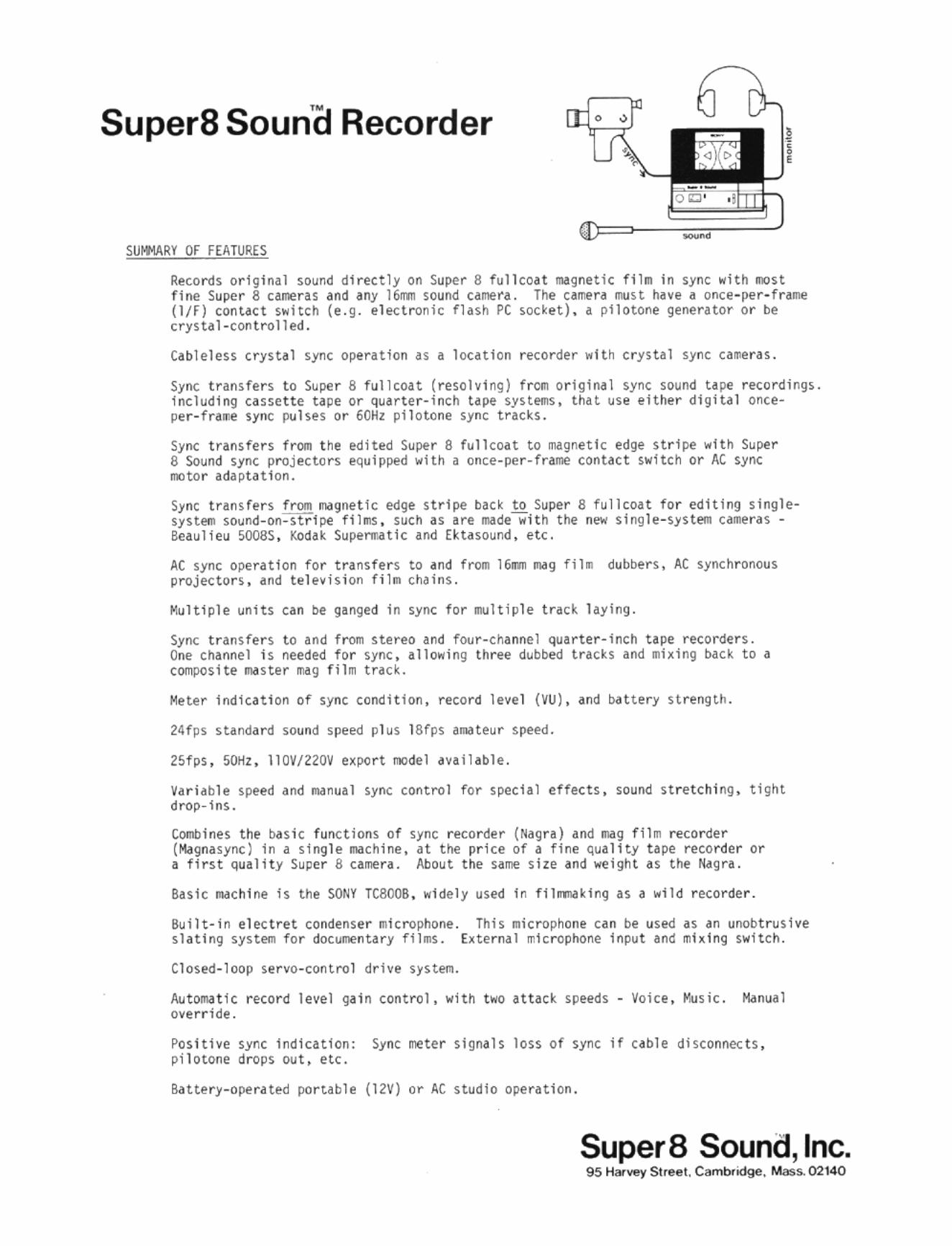
SUMMARY OF FEATURES
Reco rds original sound direct ly on Super 8 fullroat mag netic fil m in sync with IIlOst fine Super 8 cameras and any 16nT!l sound camefa . The camera must have a once- per- frame (IfF) contact switch (e .g . electronic flash PC socket), a pl1otone generator or be crystal-controlled.
Cableless crystal sync operation as a 10ntloo recorder with c rystal sync cameras .
Sync transfe rs to Super 8 fu llroat (resolving) fr(lm orlgiMl sync sound a pe recordings. including cassette tape or quarter-inch tape SyHe1IIs, tl1at use either digital onceper -fra .. e sync pulses or 60Hz pilotone sync trac~s.
Sync traf)sfers frOt'll the 8 Sound sync projectors moto r adaptation.
edited Super 8 fullco.J.t to magnetic edge stripe with Super equipped with a once-per-frame contac t switch or AC sync
Sync .",",~,:,~ system Beaulieu
baCK to Super S fullcoa t for edit ing singleas are madewith the new single- system came ras -
;"P,~;;,. i~ and Ektasound, etc.
AC sync operation for transfers to and from 16m mag fil m dubbers, AC synchronous projectors, and te1e~ision film chai ns .
"'.ulti ple units can be ganged in sync for multiple track laying .
Sync t ransfers t o and from stereo and four-channel Quar ter- inch Upe recorders. One Channel is needed fo r sync, allowing three dubbed tracks and mixing back to a comPQsite maste r rr.ag film trad .
Meter i ndicati on of sync condition, record level (VU), and bat tery strength.
24fps standard sound speed plus 18fps amateur speed.
25f ps, 501lz, 11 OV/2Z0V e~PQrt model an il ab le .
Va r iable speed dnd manual sync con t rol for spech l effects, sound stret ching, tight drop-ins.
C(Ml1bines the basic functions of s~nc recorder (Nagra) dnd mag fl1m recorder (Magnasync ) in a single machine, at the price of a fine quality tape recorder or a first quality Super S camera . About t he same she and weight a s the Nagra .
Basic mac hi ne is the SONY TCSOOB . widely used In filrrrnaking as a wil d recorde r.
Built-in electret condenser microphone . This microphone c.J.n be used as an unobt ruslve slating syste<Tl for documenUry f1]ms. External mIc rophone input an~ mixing switch .
Closed-loop servo-control dr ive s~ste!ll.
Automatle record level gai n control, wi t h t wo Ht~ck speeds - Voice, "'usic. H<lnual override.
Posjtive sync 1ndication: Sync meter signals loss of sync if cable disconnects, pilotone dro ps ou t , etc.
Battery-operated portable (12V) or AC studio opera ti on.
SuperB Sound, Inc. 95 H"' .... V Street. Cambriclge. Mass.02140