Embed Size (px)
Citation preview
8/11/2019 Supersonic Jet
http://slidepdf.com/reader/full/supersonic-jet 1/6
187
AN EXPERIMENTAL AND NUMERICAL STUDY OF A SUPERSONIC-JETSHOCK-WAVE STRUCTURE
V.I. Zapryagaev 1, A.N. Kudryavtsev 1, A.V. Lokotko 1,A.V. Solotchin 1, A.A. Pavlov 1, and A. Hadjadj 2
1Institute of Theoretical and Applied Mechanics, Siberian Branch,630090 Novosibirsk, Russia
2LMFN-CORIA, UMR CNRS 6614, INSA de Rouen,St. Etienne du Rouvray, France
The investigation of the shock-wave structure and numerical characteristics of supersonic- jet shear layer is of great importance due to numerous applications of supersonic jets inaerospace engineering. In the present work, a detailed study of a supersonic non-isobaric jetaimed at validation and further development of numerical algorithms for jet flow prediction has
been carried out. The difficulties in numerical simulation of supersonic non-isobaric jets stemfrom the necessity of accurate resolution of various flow scales and from the occurrence ofmultiple shock waves and subsonic pockets interacting with each other.
Although the literature [1, 2] contains many data on the structure of supersonic under-expanded jet flows, accurate verification of numerical predictions requires detailedmeasurements of the jet structure to be performed at a precise control over supersonic nozzlegeometry and jet flow parameters.
The experiments were performed in the jet facility of the Institute of Theoretical andApplied Mechanics (Novosibirsk) operating on cold air (specific heat ratio γ=1.4, stagnationtemperature To=287 K). The jet was exhausted into quiescent air with the ambient pressurePh=1.008 bar and ambient temperature Th=294 K.
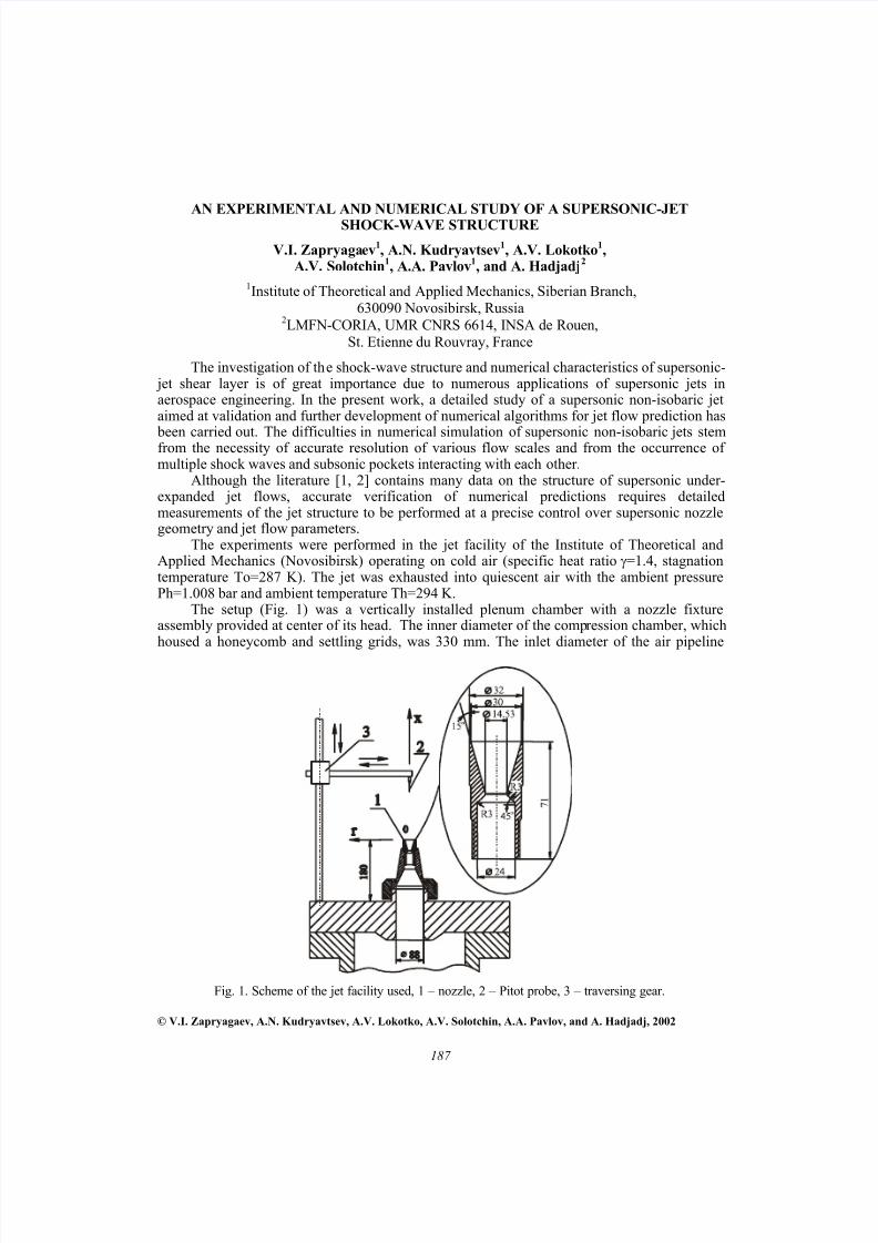
The setup (Fig. 1) was a vertically installed plenum chamber with a nozzle fixtureassembly provided at center of its head. The inner diameter of the compression chamber, whichhoused a honeycomb and settling grids, was 330 mm. The inlet diameter of the air pipeline
© V.I. Zapryagaev, A.N. Kudryavtsev, A.V. Lokotko, A.V. Solotchin, A.A. Pavlov, and A. Hadjadj, 2002
Fig. 1. Scheme of the jet facility used, 1 – nozzle, 2 – Pitot probe, 3 – traversing gear.
8/11/2019 Supersonic Jet
http://slidepdf.com/reader/full/supersonic-jet 2/6
Report Documentation Page
Report Date 23 Aug 2002
Report Type N/A
Dates Covered (from... to) -
Title and Subtitle An Experimental and Numerical Study of A Supersonic-JetShock-Wave Structure
Contract Number
Grant Number
Program Element Number
Author(s) Project Number
Task Number
Work Unit Number
Performing Organization Name(s) and Address(es) Institute of Theoretical and Applied Mechanics Institutskaya 4/1Novosibirsk 530090 Russia
Performing Organization Report Number
Sponsoring/Monitoring Agency Name(s) and Address(es) EOARD PSC 802 Box 14 FPO 09499-0014
Sponsor/Monitor’s Acronym(s)
Sponsor/Monitor’s Report Number(s)
Distribution/Availability Statement Approved for public release, distribution unlimited
Supplementary Notes See also ADM001433, Conference held International Conference on Methods of Aerophysical Research (11th) Held inNovosibirsk, Russia on 1-7 Jul 2002
Abstract
Subject Terms
Report Classification unclassified
Classification of this page unclassified
Classification of Abstract unclassified
Limitation of Abstract UU
Number of Pages 5
8/11/2019 Supersonic Jet
http://slidepdf.com/reader/full/supersonic-jet 3/6
188
through which the air was supplied to the nozle was 88 mm. The setup was equipped with atraversing gear that allowed us to scan the flow with a Pitot probe both in streamwise and radialdirections (in the interval of respective cylindrical coordinates 0< x < 720 mm and 0< r <50mm, respectively.
As a test case, a supersonic jet was selected issuing from a conical nozzle with a 15 o- half-angle at a design Mach number 3.005. The nozzle exit radius was R a=15 mm, critical diameterDcr=14.53 mm, and outer nozzle diameter 32 mm.
For the over expanded flow regime, the pressure ratios were n = P a/Ph = 0.6 and N pr = P o/Ph = 21.8 (here P a is the pressure at the nozzle exit and P o is the stagnation pressure).The distributions of the Pitot pressure along the jet axis P t(x) and the radial directions P t(r) invarious jet cross-sections were measured. The Pitot pressure was measured by Siemens pressuresensors KPY45A intended to measure pressure in the pressure range 0 to10 bars, whereas the
pressure in the plenum chamber was measured with the Siemens pressure sensors KPY68AK (0to 160 bars). The experiments were conducted using an automated data acquisition system built
around a personal computer and a 12-bit ADC.Optical visualization of the flow structure in the initial region of the jet at various plenum-
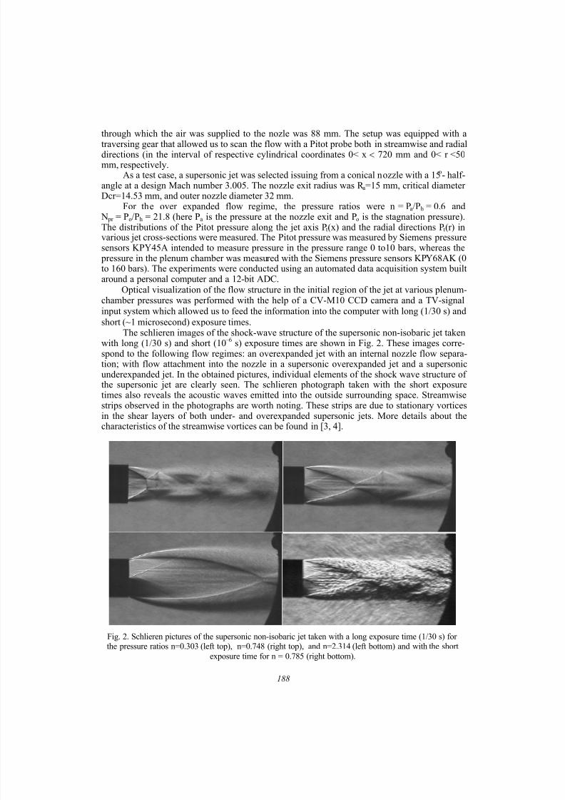
chamber pressures was performed with the help of a CV-M10 CCD camera and a TV-signalinput system which allowed us to feed the information into the computer with long (1/30 s) andshort (~1 microsecond) exposure times.
The schlieren images of the shock-wave structure of the supersonic non-isobaric jet takenwith long (1/30 s) and short (10 –6 s) exposure times are shown in Fig. 2. These images corre-spond to the following flow regimes: an overexpanded jet with an internal nozzle flow separa-tion; with flow attachment into the nozzle in a supersonic overexpanded jet and a supersonicunderexpanded jet. In the obtained pictures, individual elements of the shock wave structure ofthe supersonic jet are clearly seen. The schlieren photograph taken with the short exposuretimes also reveals the acoustic waves emitted into the outside surrounding space. Streamwisestrips observed in the photographs are worth noting. These strips are due to stationary vortices
in the shear layers of both under- and overexpanded supersonic jets. More details about thecharacteristics of the streamwise vortices can be found in [3, 4].
Fig. 2. Schlieren pictures of the supersonic non-isobaric jet taken with a long exposure time (1/30 s) forthe pressure ratios n=0.303 (left top), n=0.748 (right top), and n=2.314 (left bottom) and with the short
exposure time for n = 0.785 (right bottom).
8/11/2019 Supersonic Jet
http://slidepdf.com/reader/full/supersonic-jet 4/6
189
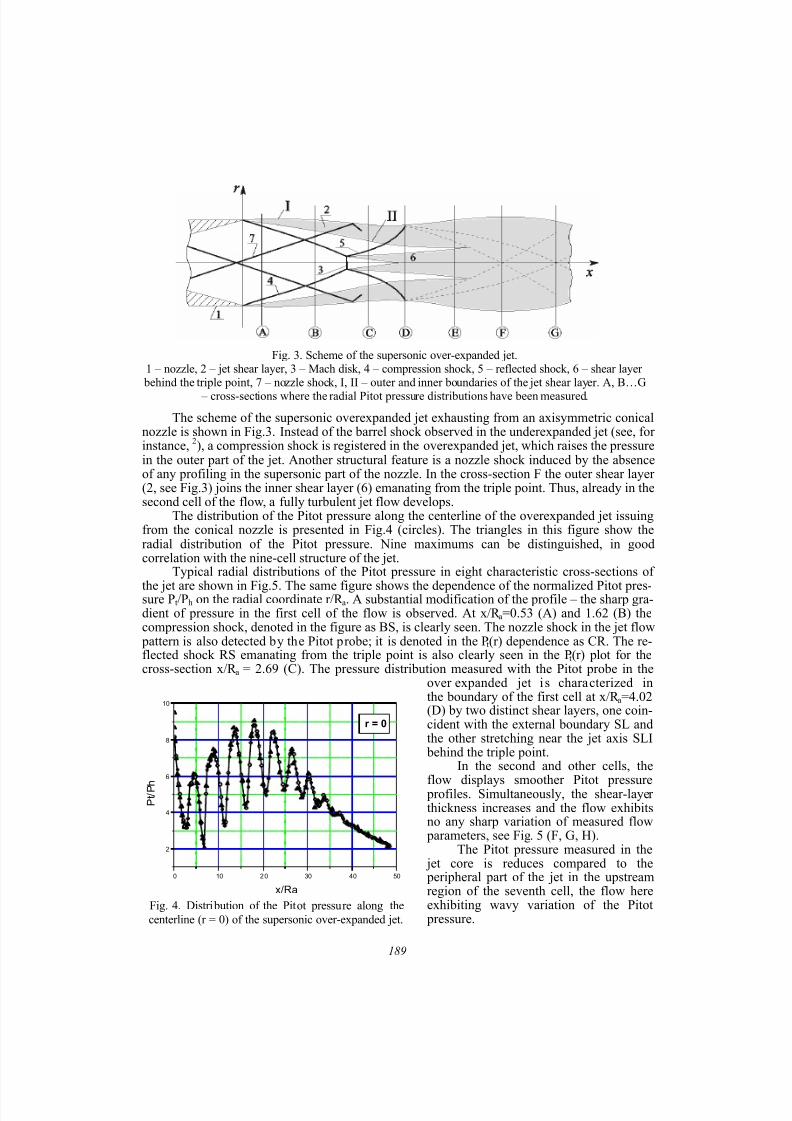
The scheme of the supersonic overexpanded jet exhausting from an axisymmetric conicalnozzle is shown in Fig.3. Instead of the barrel shock observed in the underexpanded jet (see, forinstance, 2), a compression shock is registered in the overexpanded jet, which raises the pressurein the outer part of the jet. Another structural feature is a nozzle shock induced by the absenceof any profiling in the supersonic part of the nozzle. In the cross-section F the outer shear layer(2, see Fig.3) joins the inner shear layer (6) emanating from the triple point. Thus, already in thesecond cell of the flow, a fully turbulent jet flow develops.
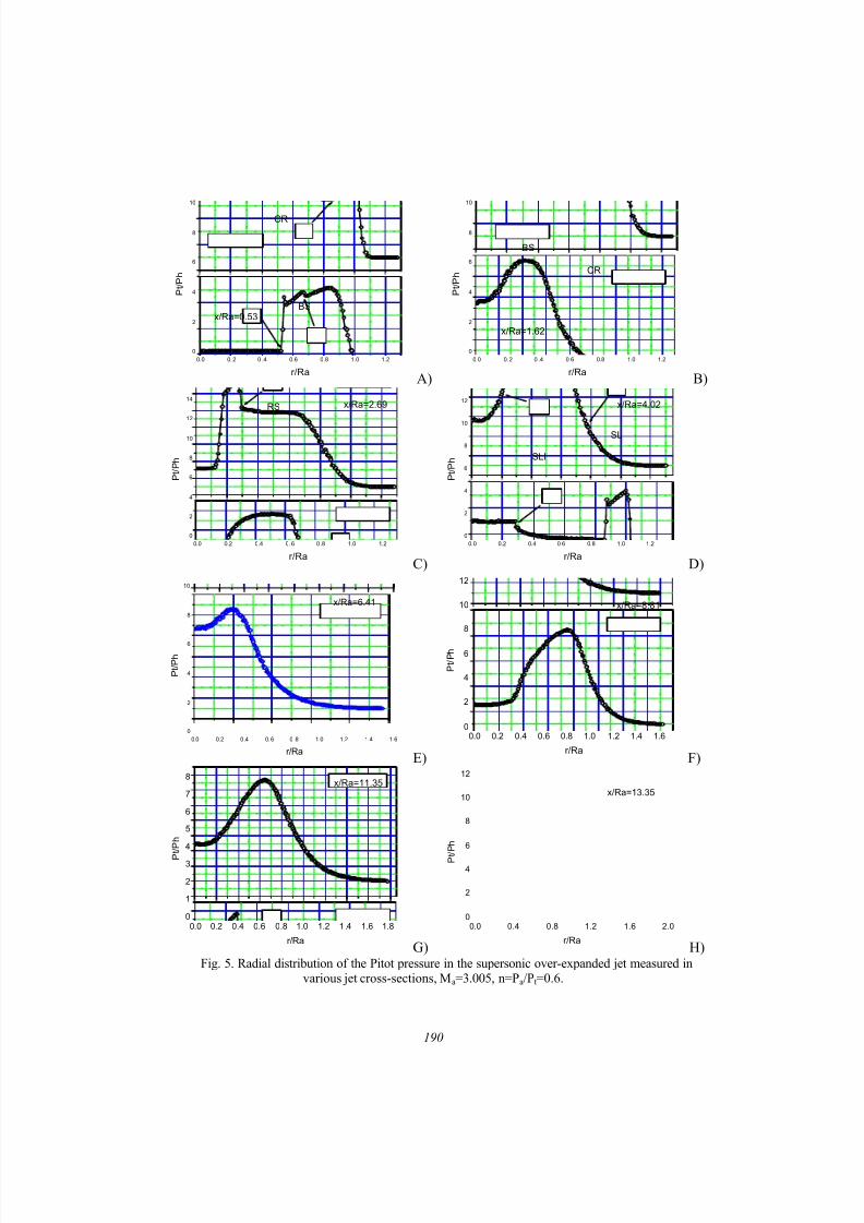
The distribution of the Pitot pressure along the centerline of the overexpanded jet issuingfrom the conical nozzle is presented in Fig.4 (circles). The triangles in this figure show theradial distribution of the Pitot pressure. Nine maximums can be distinguished, in goodcorrelation with the nine-cell structure of the jet.
Typical radial distributions of the Pitot pressure in eight characteristic cross-sections of
the jet are shown in Fig.5. The same figure shows the dependence of the normalized Pitot pres-sure P t/Ph on the radial coordinate r/R a. A substantial modification of the profile – the sharp gra-dient of pressure in the first cell of the flow is observed. At x/R a=0.53 (A) and 1.62 (B) thecompression shock, denoted in the figure as BS, is clearly seen. The nozzle shock in the jet flow
pattern is also detected by the Pitot probe; it is denoted in the P t(r) dependence as CR. The re-flected shock RS emanating from the triple point is also clearly seen in the P t(r) plot for thecross-section x/R a = 2.69 (C). The pressure distribution measured with the Pitot probe in the
over expanded jet i s characterized inthe boundary of the first cell at x/R a=4.02(D) by two distinct shear layers, one coin-cident with the external boundary SL andthe other stretching near the jet axis SLI
behind the triple point.In the second and other cells, the
flow displays smoother Pitot pressure profiles. Simultaneously, the shear-layerthickness increases and the flow exhibitsno any sharp variation of measured flow
parameters, see Fig. 5 (F, G, H).The Pitot pressure measured in the
jet core is reduces compared to the peripheral part of the jet in the upstreamregion of the seventh cell, the flow hereexhibiting wavy variation of the Pitot
pressure.
Fig. 3. Scheme of the supersonic over-expanded jet.1 – nozzle, 2 – jet shear layer, 3 – Mach disk, 4 – compression shock, 5 – reflected shock, 6 – shear layer
behind the triple point, 7 – nozzle shock, I, II – outer and inner boundaries of the jet shear layer. A, B…G – cross-sections where the radial Pitot pressure distributions have been measured.
Fig. 4. Distribution of the Pitot pressure along thecenterline (r = 0) of the supersonic over-expanded jet.
0 10 2 0 30 40 50
2
4
6
8
10
r = 0
P t / P h
x/Ra
8/11/2019 Supersonic Jet
http://slidepdf.com/reader/full/supersonic-jet 5/6
190
0.0 0. 2 0 .4 0.6 0.8 1.0 1 .2
0
2
4
6
8
10
BS
CR
x/Ra=0.53
P t / P h
r/RaA)
0.0 0. 2 0 .4 0.6 0.8 1.0 1.2
0
2
4
6
8
10
CR
BS
x/Ra=1.62
P t / P h
r/RaB)
0.0 0.2 0.4 0. 6 0 .8 1.0 1.2
0
2
4
6
8
10
12
14
RS x/Ra=2.69
P t / P h
r/RaC)
0.0 0.2 0.4 0.6 0.8 1.0 1.2
0
2
4
6
8
10
12
SLI
SL
x/Ra=4.02
P t / P h
r/RaD)
0.0 0.2 0.4 0. 6 0 .8 1.0 1.2 1.4 1.6
0
2
4
6
8
10
x/Ra=6.41
P t / P h
r/RaE)
0.0 0.2 0.4 0.6 0.8 1.0 1.2 1.4 1.60
2
4
6
8
10
12
x/Ra=8.81
P t / P h
r/RaF)
0.0 0.2 0.4 0.6 0.8 1.0 1.2 1 .4 1.6 1.80
1
2
3
4
5
6
7
8x/Ra=11.35
P
t / P h
r/RaG)
0.0 0.4 0.8 1.2 1.6 2.00
2
4
6
8
10
12
x/Ra=13.35
P t / P h
r/RaH)
Fig. 5. Radial distribution of the Pitot pressure in the supersonic over-expanded jet measured invarious jet cross-sections, M a=3.005, n=P a/P t=0.6.
8/11/2019 Supersonic Jet
http://slidepdf.com/reader/full/supersonic-jet 6/6
191
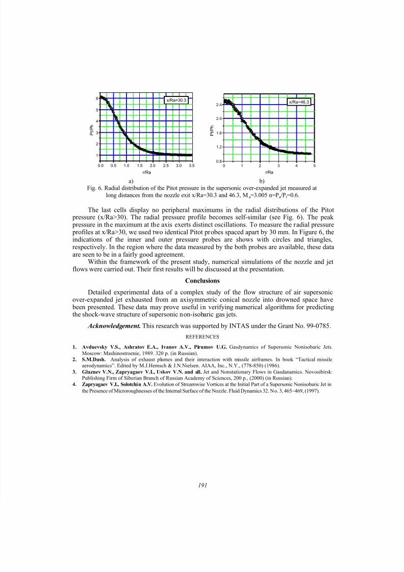
The last cells display no peripheral maximums in the radial distributions of the Pitot pressure (x/Ra>30). The radial pressure profile becomes self-similar (see Fig. 6). The peak pressure in the maximum at the axis exerts distinct oscillations. To measure the radial pressure profiles at x/Ra>30, we used two identical Pitot probes spaced apart by 30 mm. In Figure 6, theindications of the inner and outer pressure probes are shows with circles and triangles,respectively. In the region where the data measured by the both probes are available, these dataare seen to be in a fairly good agreement.
Within the framework of the present study, numerical simulations of the nozzle and jetflows were carried out. Their first results will be discussed at the presentation.
Conclusions
Detailed experimental data of a complex study of the flow structure of air supersonic
over-expanded jet exhausted from an axisymmetric conical nozzle into drowned space have been presented. These data may prove useful in verifying numerical algorithms for predictingthe shock-wave structure of supersonic non-isobaric gas jets.
Acknowledgement. This research was supported by INTAS under the Grant No. 99-0785.
REFERENCES
1. Avduevsky V.S., Ashratov E.A., Ivanov A.V., Pirumov U.G. Gasdynamics of Supersonic Nonisobaric Jets.Moscow: Mashinostroenie, 1989. 320 p. (in Russian).
2. S.M.Dash. Analysis of exhaust plumes and their interaction with missile airframes. In book “Tactical missileaerodynamics”. Edited by M.J.Hemsch & J.N.Nielsen. AIAA, Inc., N.Y., (778-850) (1986).
3. Glaznev V.N., Zapryagaev V.I., Uskov V.N. and all. Jet and Nonstationary Flows in Gasdanamics. Novosibirsk:Publishing Firm of Siberian Branch of Russian Academy of Sciences, 200 p., (2000) (in Russian).
4. Zapryagaev V.I., Solotchin A.V. Evolution of Streamwise Vortices at the Initial Part of a Supersonic Nonisobaric Jet inthe Presence of Microroughnesses of the Internal Surface of the Nozzle. Fluid Dynamics 32. No. 3, 465 −469, (1997).
0.0 0.5 1.0 1.5 2.0 2.5 3.0 3.5
1
2
3
4
5
6x/Ra=30.3
P t / P h
r/Ra
0 1 2 3 4 50.8
1.2
1.6
2.0
2.4 x/Ra=46.3
P t / P h
r/Ra
a) b)Fig. 6. Radial distribution of the Pitot pressure in the supersonic over-expanded jet measured at
long distances from the nozzle exit x/Ra=30.3 and 46.3, M a=3.005 n=P a/P t=0.6.