Embed Size (px)
Citation preview
SuperSpeed InterChip
Link Test Specification
Revision 0.6
Date: March 20, 2014
Revision: 0.6
Revision History
Revision Issue Date Comments
0.1 5/7/2012 Started doc, added asserts, some definitions and timers.
Added link tests – need to go through and change for M-
PHY
3/20/2014
SSIC Link Tests Specification [Rev 0.6]
0.2 5/16/2012 Cleaned up asserts, added timers from SSIC 1.0 RC
spec.
0.3 11/29/2012 Changed TDs to reflect SSIC M-PHY states
0.4 1/10/2013 Asserts mapped to TDs
0.45 10/9/2013 Update asserts to Sept SSIC Spec revision
0.6 3/20/14 Asserts and TDs done
Intellectual Property Disclaimer
THIS DOCUMENT IS PROVIDED “AS IS” WITH NO WARRANTIES WHATSOEVER INCLUDING ANY WARRANTY OF MERCHANTABILITY, FITNESS FOR ANY PARTICULAR PURPOSE, OR ANY WARRANTY OTHERWISE ARISING OUT OF ANY PROPOSAL, SPECIFICATION, OR SAMPLE.
A COPYRIGHT LICENSE IS HEREBY GRANTED TO REPRODUCE AND DISTRIBUTE THIS DOCUMENT FOR INTERNAL USE ONLY. NO OTHER LICENSE, EXPRESS OR IMPLIED, BY ESTOPPEL OR OTHERWISE, TO ANY OTHER INTELLECTUAL PROPERTY RIGHTS IS GRANTED OR INTENDED HEREBY.
INTEL CORPORATION AND THE AUTHORS OF THIS DOCUMENT DISCLAIM ALL LIABILITY, INCLUDING LIABILITY FOR INFRINGEMENT OF PROPRIETARY RIGHTS, RELATING TO IMPLEMENTATION OF INFORMATION IN THIS DOCUMENT. INTEL CORPORATION AND THE AUTHORS OF THIS DOCUMENT ALSO DO NOT WARRANT OR REPRESENT THAT SUCH IMPLEMENTATION(S) WILL NOT INFRINGE SUCH RIGHTS.
ALL SUGGESTIONS OR FEEDBACK RELATED TO THIS DOCUMENT BECOME THE PROPERTY OF INTEL CORPORATION UPON SUBMISSION.
INTEL CORPORATION MAY MAKE CHANGES TO THIS DOCUMENT, SPECIFICATIONS, PRODUCT DESCRIPTIONS, AND PLANS AT ANY TIME, WITHOUT NOTICE.
Notice: Implementations developed using the information provided in this document may infringe the patent rights of various parties including the parties involved in the development of this document. No license, express or implied, by estoppel or otherwise, to any intellectual property rights (including without limitation rights under any party’s patents) are granted herein.
This document is an intermediate draft for comment only and is subject to change without notice. Readers should not design products based solely on these documents but should use the USB IF specifications available through the USB IF. The specifications available through the USB IF have the final authority in any and all cases where a conflict or difference between this specification and the specifications seem to occur.
3/20/2014
SSIC Link Tests Specification [Rev 0.6]
All product and specification names are trademarks, registered trademarks, or service marks of their respective owners.
Copyright © 2012 Intel. All rights reserved.
.
Significant Contributors:
Please send comments via electronic mail to: [email protected] or [email protected] or
SSIC Link Tests Specification [Rev 0.6] 2
1 SSIC TESTING REQUIREMENTS ................................................................................................................. 4
2 TERMS AND ABBREVIATIONS .................................................................................................................... 5
3 TEST ASSERTIONS....................................................................................................................................... 5
4 PHY PROFILES ............................................................................................................................................ 17
5 TIMERS AND DEFINITIONS ........................................................................................................................ 18
6 SSIC LINK TEST DESCRIPTIONS .............................................................................................................. 20
6.1 Link Initialization Sequence .............................................................................................................. 20
TD 3.1 Link Initialization Sequence ......................................................................................................... 20
6.2 Physical Layer ..................................................................................................................................... 21
TD 3.2 Skip Test ....................................................................................................................................... 21
TD 3.3 Elasticity Buffer Test .................................................................................................................... 22
6.3 Link Layer ........................................................................................................................................... 22
TD 3.4 Link Bring-up Test ....................................................................................................................... 22
TD 3.5 Link Commands Framings Robustness Test................................................................................. 24
TD 3.6 Link Commands CRC-5 Robustness Test .................................................................................... 25
TD 3.7 Invalid Link Commands Test ....................................................................................................... 25
TD 3.8 Header Packet Framing Robustness Test ...................................................................................... 26
TD 3.9 Data Payload Packet Framing Robustness Test ............................................................................ 26
TD 3.10 RX Header Packet Retransmission Test ................................................................................... 27
TD 3.11 TX Header Packet Retransmission Test ................................................................................... 29
TD 3.12 PENDING_HP_TIMER Deadline Test .................................................................................... 29
TD 3.13 CREDIT_HP_TIMER Deadline Test ....................................................................................... 30
TD 3.14 PENDING_HP_TIMER Timeout Test ..................................................................................... 30
TD 3.15 CREDIT_HP_TIMER Timeout Test ........................................................................................ 31
TD 3.16 Wrong Header Sequence Test ................................................................................................... 31
TD 3.17 Wrong LGOOD_N Sequence Test ........................................................................................... 32
TD 3.18 Wrong LCRD_X Sequence Test ............................................................................................... 32
TD 3.19 Link Command Missing Test (Upstream Port Only) ................................................................ 33
TD 3.20 tPortConfiguration Time Timeout Test .................................................................................... 33
TD 3.21 Low Power initiation for U1 test (Downstream Port Only) ...................................................... 34
TD 3.22 Low Power initiation for U2 test (Downstream Port Only) ...................................................... 35
TD 3.23 PM_LC_TIMER Deadline Test (Downstream Port Only) ....................................................... 36
TD 3.24 PM_LC_TIMER Timeout Test (Downstream Port Only) ........................................................ 36
TD 3.25 PM_ENTRY_TIMER Timeout Test (Upstream Port Only) ..................................................... 37
TD 3.26 Accepted Power Management Transaction for U1 Test (Upstream Port Only) ........................ 37
TD 3.27 Accepted Power Management Transaction for U2 Test (Upstream Port Only) ........................ 38
TD 3.28 Accepted Power Management Transaction for U3 Test (Upstream Port Only) ........................ 39
3/20/2014
3 SSIC Link Tests Specification [Rev 0.6]
TD 3.29 Transition to U0 from Recovery Test ....................................................................................... 39
TD 3.30 Hot Reset Detection in Polling Test (Upstream Port Only) ...................................................... 41
TD 3.31 Hot Reset Detection in U0 Test (Upstream Port Only)............................................................. 41
TD 3.32 Hot Reset Initiation in U0 Test (Downstream Port Only)......................................................... 42
TD 3.33 Recovery on three consecutive failed RX Header Packets Test ............................................... 43
TD 3.34 Hot Reset Failure Test (Downstream Port Only) ...................................................................... 44
TD 3.35 Exit U3 by Reset Test (Downstream Port Only)....................................................................... 45
TD 3.36 Exit U3 Test (Host Downstream Port Only) ............................................................................. 46
TD 3.37 Packet Pending Test (Upstream Port Only) .............................................................................. 46
SSIC Link Tests Specification [Rev 0.6] 4
1 SSIC Testing Requirements
In order to receive a logo, SSIC compliant devices must pass the following:
Interoperability Tests
Framework Tests [Chapter 9 Tests]
Link Tests
Electrical Tests
This test spec covers Link Tests.
To run Link Tests the product under test must provide SMA connectors.
3/20/2014
5 SSIC Link Tests Specification [Rev 0.6]
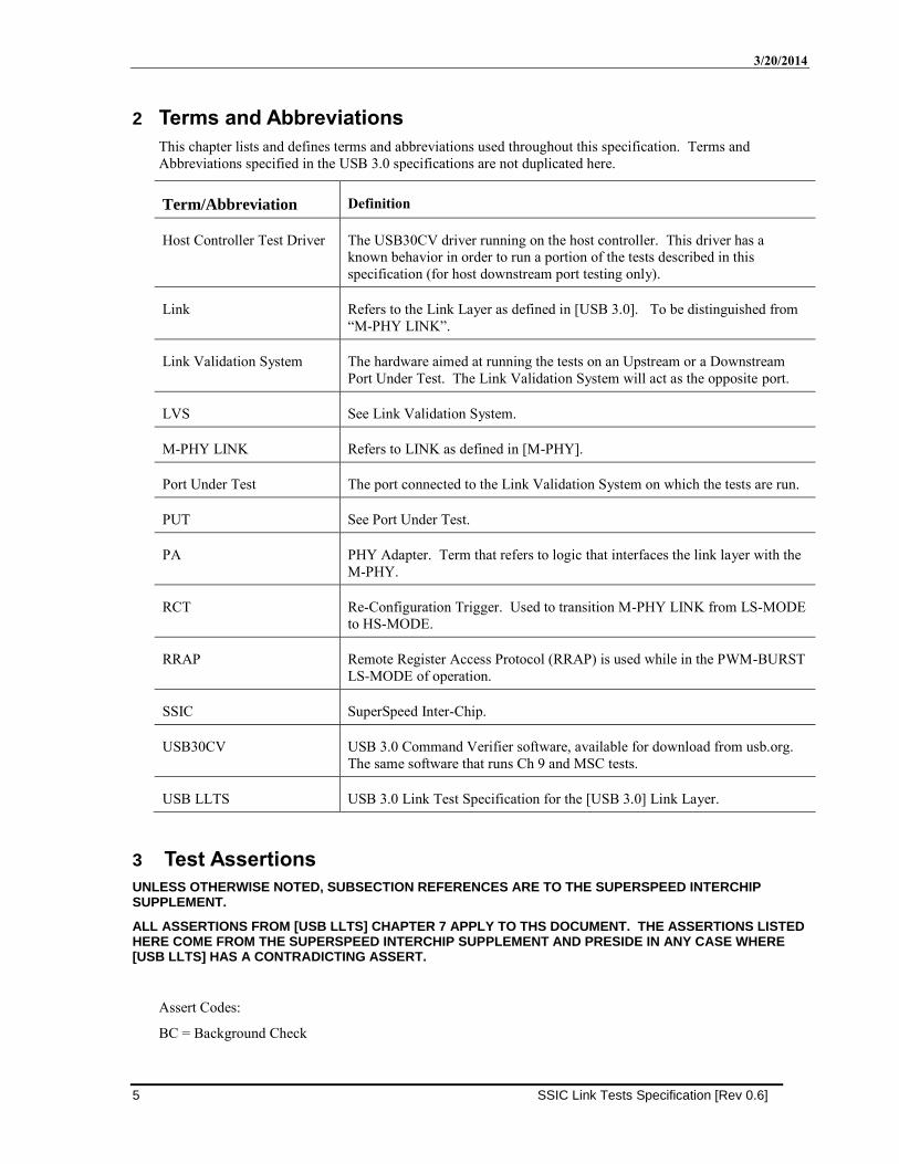
2 Terms and Abbreviations
This chapter lists and defines terms and abbreviations used throughout this specification. Terms and
Abbreviations specified in the USB 3.0 specifications are not duplicated here.
Term/Abbreviation Definition
Host Controller Test Driver The USB30CV driver running on the host controller. This driver has a
known behavior in order to run a portion of the tests described in this
specification (for host downstream port testing only).
Link Refers to the Link Layer as defined in [USB 3.0]. To be distinguished from
“M-PHY LINK”.
Link Validation System The hardware aimed at running the tests on an Upstream or a Downstream
Port Under Test. The Link Validation System will act as the opposite port.
LVS See Link Validation System.
M-PHY LINK Refers to LINK as defined in [M-PHY].
Port Under Test The port connected to the Link Validation System on which the tests are run.
PUT See Port Under Test.
PA PHY Adapter. Term that refers to logic that interfaces the link layer with the
M-PHY.
RCT Re-Configuration Trigger. Used to transition M-PHY LINK from LS-MODE
to HS-MODE.
RRAP Remote Register Access Protocol (RRAP) is used while in the PWM-BURST
LS-MODE of operation.
SSIC SuperSpeed Inter-Chip.
USB30CV USB 3.0 Command Verifier software, available for download from usb.org.
The same software that runs Ch 9 and MSC tests.
USB LLTS USB 3.0 Link Test Specification for the [USB 3.0] Link Layer.
3 Test Assertions
UNLESS OTHERWISE NOTED, SUBSECTION REFERENCES ARE TO THE SUPERSPEED INTERCHIP SUPPLEMENT.
ALL ASSERTIONS FROM [USB LLTS] CHAPTER 7 APPLY TO THS DOCUMENT. THE ASSERTIONS LISTED HERE COME FROM THE SUPERSPEED INTERCHIP SUPPLEMENT AND PRESIDE IN ANY CASE WHERE [USB LLTS] HAS A CONTRADICTING ASSERT.
Assert Codes:
BC = Background Check
SSIC Link Tests Specification [Rev 0.6] 6
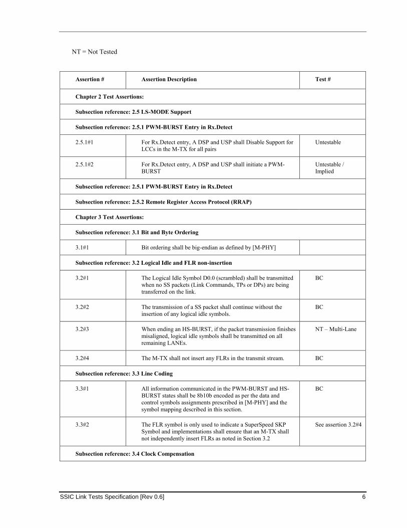
NT = Not Tested
Assertion # Assertion Description Test #
Chapter 2 Test Assertions:
Subsection reference: 2.5 LS-MODE Support
Subsection reference: 2.5.1 PWM-BURST Entry in Rx.Detect
2.5.1#1 For Rx.Detect entry, A DSP and USP shall Disable Support for
LCCs in the M-TX for all pairs
Untestable
2.5.1#2 For Rx.Detect entry, A DSP and USP shall initiate a PWM-
BURST
Untestable /
Implied
Subsection reference: 2.5.1 PWM-BURST Entry in Rx.Detect
Subsection reference: 2.5.2 Remote Register Access Protocol (RRAP)
Chapter 3 Test Assertions:
Subsection reference: 3.1 Bit and Byte Ordering
3.1#1 Bit ordering shall be big-endian as defined by [M-PHY]
Subsection reference: 3.2 Logical Idle and FLR non-insertion
3.2#1 The Logical Idle Symbol D0.0 (scrambled) shall be transmitted
when no SS packets (Link Commands, TPs or DPs) are being
transferred on the link.
BC
3.2#2 The transmission of a SS packet shall continue without the
insertion of any logical idle symbols.
BC
3.2#3 When ending an HS-BURST, if the packet transmission finishes
misaligned, logical idle symbols shall be transmitted on all
remaining LANEs.
NT – Multi-Lane
3.2#4 The M-TX shall not insert any FLRs in the transmit stream. BC
Subsection reference: 3.3 Line Coding
3.3#1 All information communicated in the PWM-BURST and HS-
BURST states shall be 8b10b encoded as per the data and
control symbols assignments prescribed in [M-PHY] and the
symbol mapping described in this section.
BC
3.3#2 The FLR symbol is only used to indicate a SuperSpeed SKP
Symbol and implementations shall ensure that an M-TX shall
not independently insert FLRs as noted in Section 3.2
See assertion 3.2#4
Subsection reference: 3.4 Clock Compensation
3/20/2014
7 SSIC Link Tests Specification [Rev 0.6]
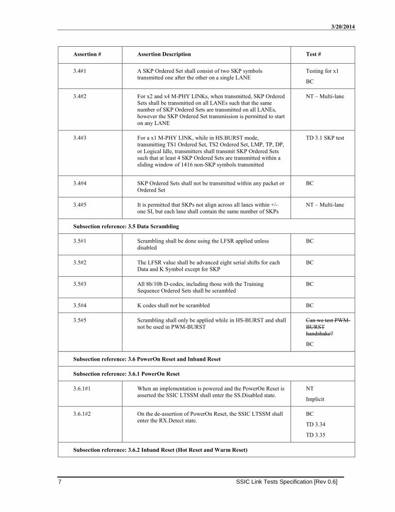
Assertion # Assertion Description Test #
3.4#1 A SKP Ordered Set shall consist of two SKP symbols
transmitted one after the other on a single LANE
Testing for x1
BC
3.4#2 For x2 and x4 M-PHY LINKs, when transmitted, SKP Ordered
Sets shall be transmitted on all LANEs such that the same
number of SKP Ordered Sets are transmitted on all LANEs,
however the SKP Ordered Set transmission is permitted to start
on any LANE
NT – Multi-lane
3.4#3 For a x1 M-PHY LINK, while in HS.BURST mode,
transmitting TS1 Ordered Set, TS2 Ordered Set, LMP, TP, DP,
or Logical Idle, transmitters shall transmit SKP Ordered Sets
such that at least 4 SKP Ordered Sets are transmitted within a
sliding window of 1416 non-SKP symbols transmitted
TD 3.1 SKP test
3.4#4 SKP Ordered Sets shall not be transmitted within any packet or
Ordered Set
BC
3.4#5 It is permitted that SKPs not align across all lanes within +/-
one SI, but each lane shall contain the same number of SKPs
NT – Multi-lane
Subsection reference: 3.5 Data Scrambling
3.5#1 Scrambling shall be done using the LFSR applied unless
disabled
BC
3.5#2 The LFSR value shall be advanced eight serial shifts for each
Data and K Symbol except for SKP
BC
3.5#3 All 8b/10b D-codes, including those with the Training
Sequence Ordered Sets shall be scrambled
BC
3.5#4 K codes shall not be scrambled BC
3.5#5 Scrambling shall only be applied while in HS-BURST and shall
not be used in PWM-BURST
Can we test PWM-
BURST
handshake?
BC
Subsection reference: 3.6 PowerOn Reset and Inband Reset
Subsection reference: 3.6.1 PowerOn Reset
3.6.1#1 When an implementation is powered and the PowerOn Reset is
asserted the SSIC LTSSM shall enter the SS.Disabled state.
NT
Implicit
3.6.1#2 On the de-assertion of PowerOn Reset, the SSIC LTSSM shall
enter the RX.Detect state.
BC
TD 3.34
TD 3.35
Subsection reference: 3.6.2 Inband Reset (Hot Reset and Warm Reset)
SSIC Link Tests Specification [Rev 0.6] 8
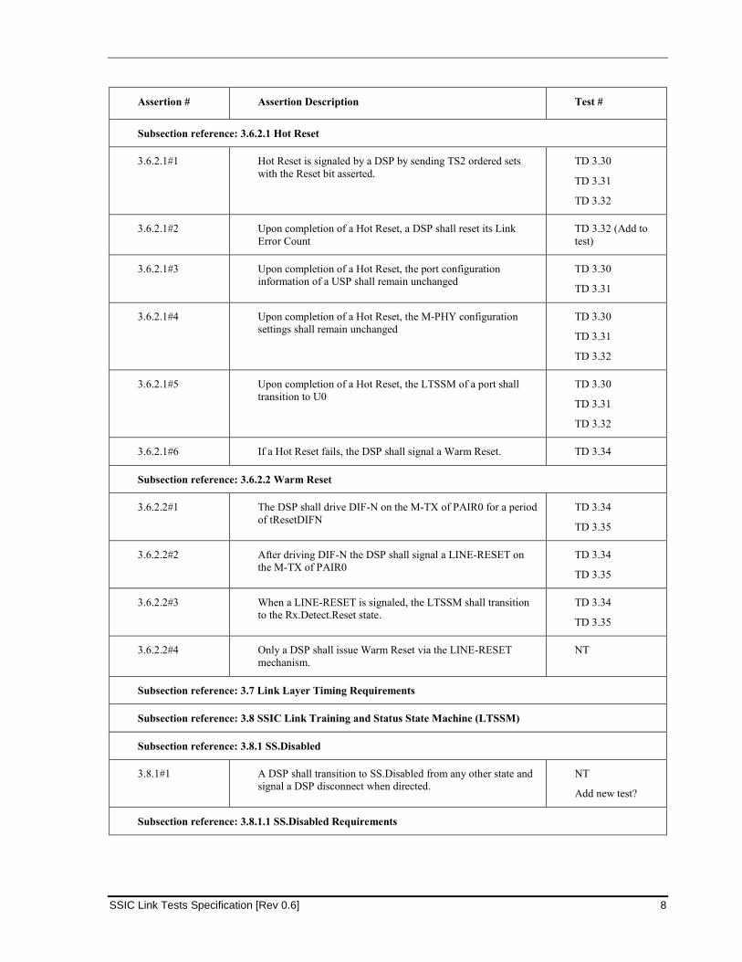
Assertion # Assertion Description Test #
Subsection reference: 3.6.2.1 Hot Reset
3.6.2.1#1 Hot Reset is signaled by a DSP by sending TS2 ordered sets
with the Reset bit asserted.
TD 3.30
TD 3.31
TD 3.32
3.6.2.1#2 Upon completion of a Hot Reset, a DSP shall reset its Link
Error Count
TD 3.32 (Add to
test)
3.6.2.1#3 Upon completion of a Hot Reset, the port configuration
information of a USP shall remain unchanged
TD 3.30
TD 3.31
3.6.2.1#4 Upon completion of a Hot Reset, the M-PHY configuration
settings shall remain unchanged
TD 3.30
TD 3.31
TD 3.32
3.6.2.1#5 Upon completion of a Hot Reset, the LTSSM of a port shall
transition to U0
TD 3.30
TD 3.31
TD 3.32
3.6.2.1#6 If a Hot Reset fails, the DSP shall signal a Warm Reset. TD 3.34
Subsection reference: 3.6.2.2 Warm Reset
3.6.2.2#1 The DSP shall drive DIF-N on the M-TX of PAIR0 for a period
of tResetDIFN
TD 3.34
TD 3.35
3.6.2.2#2 After driving DIF-N the DSP shall signal a LINE-RESET on
the M-TX of PAIR0
TD 3.34
TD 3.35
3.6.2.2#3 When a LINE-RESET is signaled, the LTSSM shall transition
to the Rx.Detect.Reset state.
TD 3.34
TD 3.35
3.6.2.2#4 Only a DSP shall issue Warm Reset via the LINE-RESET
mechanism.
NT
Subsection reference: 3.7 Link Layer Timing Requirements
Subsection reference: 3.8 SSIC Link Training and Status State Machine (LTSSM)
Subsection reference: 3.8.1 SS.Disabled
3.8.1#1 A DSP shall transition to SS.Disabled from any other state and
signal a DSP disconnect when directed.
NT
Add new test?
Subsection reference: 3.8.1.1 SS.Disabled Requirements
3/20/2014
9 SSIC Link Tests Specification [Rev 0.6]
Assertion # Assertion Description Test #
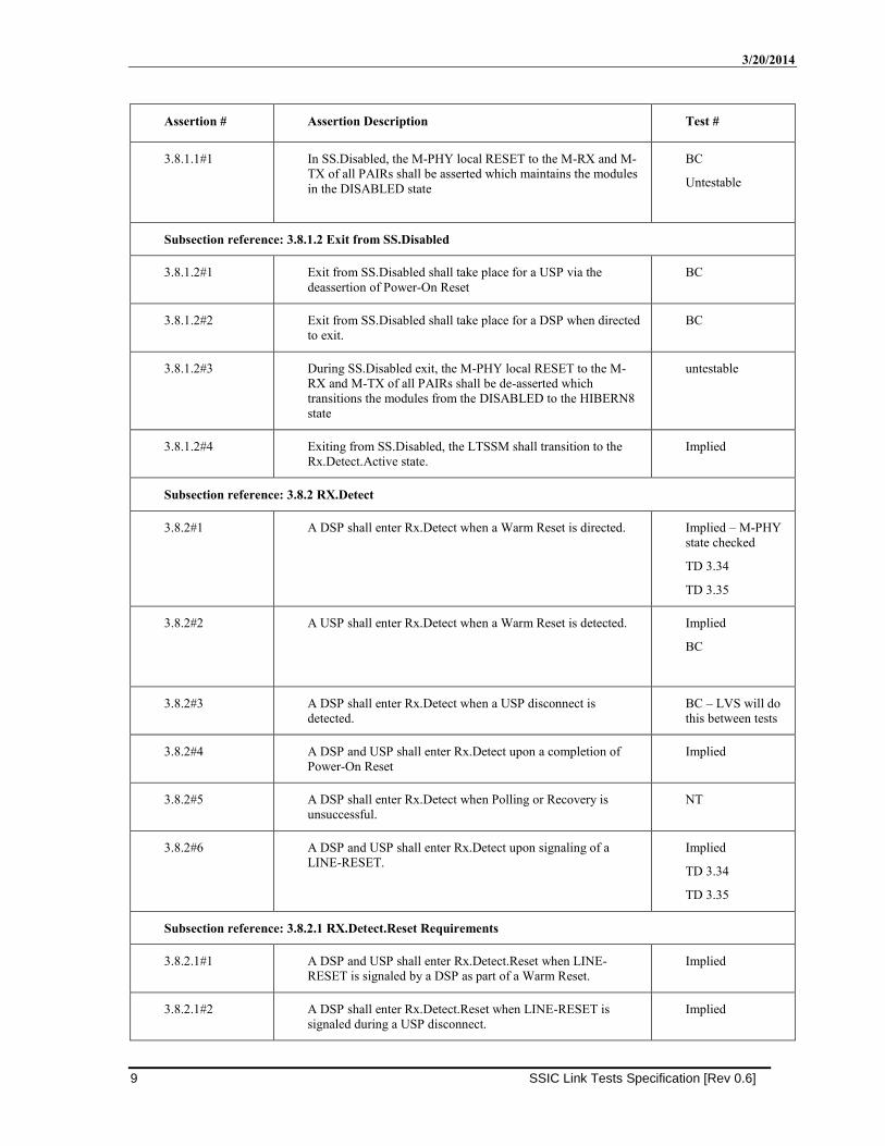
3.8.1.1#1 In SS.Disabled, the M-PHY local RESET to the M-RX and M-
TX of all PAIRs shall be asserted which maintains the modules
in the DISABLED state
BC
Untestable
Subsection reference: 3.8.1.2 Exit from SS.Disabled
3.8.1.2#1 Exit from SS.Disabled shall take place for a USP via the
deassertion of Power-On Reset
BC
3.8.1.2#2 Exit from SS.Disabled shall take place for a DSP when directed
to exit.
BC
3.8.1.2#3 During SS.Disabled exit, the M-PHY local RESET to the M-
RX and M-TX of all PAIRs shall be de-asserted which
transitions the modules from the DISABLED to the HIBERN8
state
untestable
3.8.1.2#4 Exiting from SS.Disabled, the LTSSM shall transition to the
Rx.Detect.Active state.
Implied
Subsection reference: 3.8.2 RX.Detect
3.8.2#1 A DSP shall enter Rx.Detect when a Warm Reset is directed. Implied – M-PHY
state checked
TD 3.34
TD 3.35
3.8.2#2 A USP shall enter Rx.Detect when a Warm Reset is detected. Implied
BC
3.8.2#3 A DSP shall enter Rx.Detect when a USP disconnect is
detected.
BC – LVS will do
this between tests
3.8.2#4 A DSP and USP shall enter Rx.Detect upon a completion of
Power-On Reset
Implied
3.8.2#5 A DSP shall enter Rx.Detect when Polling or Recovery is
unsuccessful.
NT
3.8.2#6 A DSP and USP shall enter Rx.Detect upon signaling of a
LINE-RESET.
Implied
TD 3.34
TD 3.35
Subsection reference: 3.8.2.1 RX.Detect.Reset Requirements
3.8.2.1#1 A DSP and USP shall enter Rx.Detect.Reset when LINE-
RESET is signaled by a DSP as part of a Warm Reset.
Implied
3.8.2.1#2 A DSP shall enter Rx.Detect.Reset when LINE-RESET is
signaled during a USP disconnect.
Implied
SSIC Link Tests Specification [Rev 0.6] 10
Assertion # Assertion Description Test #
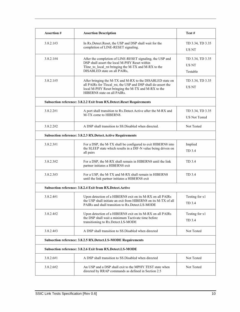
3.8.2.1#3 In Rx.Detect.Reset, the USP and DSP shall wait for the
completion of LINE-RESET signaling.
TD 3.34, TD 3.35
US NT
3.8.2.1#4 After the completion of LINE-RESET signaling, the USP and
DSP shall assert the local M-PHY Reset within
Tline_to_local_rst bringing the M-TX and M-RX to the
DISABLED state on all PAIRs,
TD 3.34, TD 3.35
US NT
Testable
3.8.2.1#5 After bringing the M-TX and M-RX to the DISABLED state on
all PAIRs for Tlocal_rst, the USP and DSP shall de-assert the
local M-PHY Reset bringing the M-TX and M-RX to the
HIBERN8 state on all PAIRs.
TD 3.34, TD 3.35
US NT
Subsection reference: 3.8.2.2 Exit from RX.Detect.Reset Requirements
3.8.2.2#1 A port shall transition to Rx.Detect.Active after the M-RX and
M-TX come to HIBERN8.
TD 3.34, TD 3.35
US Not Tested
3.8.2.2#2 A DSP shall transition to SS.Disabled when directed. Not Tested
Subsection reference: 3.8.2.3 RX.Detect.Active Requirements
3.8.2.3#1 For a DSP, the M-TX shall be configured to exit HIBERN8 into
the SLEEP state which results in a DIF-N value being driven on
all pairs
Implied
TD 3.4
3.8.2.3#2 For a DSP, the M-RX shall remain in HIBERN8 until the link
partner initiates a HIBERN8 exit
TD 3.4
3.8.2.3#3 For a USP, the M-TX and M-RX shall remain in HIBERN8
until the link partner initiates a HIBERN8 exit
TD 3.4
Subsection reference: 3.8.2.4 Exit from RX.Detect.Active
3.8.2.4#1 Upon detection of a HIBERN8 exit on its M-RX on all PAIRs
the USP shall initiate an exit from HIBERN8 on its M-TX of all
PAIRs and shall transition to Rx.Detect.LS-MODE
Testing for x1
TD 3.4
3.8.2.4#2 Upon detection of a HIBERN8 exit on its M-RX on all PAIRs
the DSP shall wait a minimum Tactivate time before
transitioning to Rx.Detect.LS-MODE
Testing for x1
TD 3.4
3.8.2.4#3 A DSP shall transition to SS.Disabled when directed Not Tested
Subsection reference: 3.8.2.5 RX.Detect.LS-MODE Requirements
Subsection reference: 3.8.2.6 Exit from RX.Detect.LS-MODE
3.8.2.6#1 A DSP shall transition to SS.Disabled when directed Not Tested
3.8.2.6#2 An USP and a DSP shall exit to the MPHY.TEST state when
directed by RRAP commands as defined in Section 2.5
Not Tested

3/20/2014
11 SSIC Link Tests Specification [Rev 0.6]
Assertion # Assertion Description Test #
3.8.2.6#3 An USP and a DSP shall execute a RCT to exit this sub-state
and enter Polling when directed to do so using the RRAP as
defined in Section 2.5.3
TD 3.4
3.8.2.6#4 After executing an RCT, the M-TX shall wait for a period equal
to the RX_Min_ActivateTime_Capability defined in Section
2.2.3 prior to exiting this sub-state into the Polling state.
TD 3.4
Subsection reference: 3.8.3 Polling
Subsection reference: 3.8.3.1 Polling.STALL Requirements
3.8.3.1#1 The M-TX and M-RX are in the STALL state. Implied
3.8.3.1#2 Exit from this sub-state should be completed within
tPollingSTALLResidency
TD 3.4
Subsection reference: 3.8.3.1 Polling.STALL Requirements
Subsection reference: 3.8.3.2 Exit from Polling.STALL
3.8.3.2#1 The M-TX shall be transitioned to enter HS-BURST as per [M-
PHY].
Implicit
3.8.3.2#2 After the M-TX enters HS-BURST, a timer shall be started and
set to expire after tRetrain.
Untestable
3.8.3.2#3 After setting the tRetrain timer, the LTSSM shall transition to
Polling.Active
Implied
Subsection reference: 3.8.3.3 Polling.Active/Configuration/Idle Requirements
3.8.3.3#1 If the tRetrain timer expires, M-TX shall be cycled from HS-
BURST to STALL and then back to HS-BURST, and the
tRetrain timer shall then be restarted
Incomplete Test
TD 3.4
3.8.3.3#2 The M-TX and M-RX shall remain in the HS-BURST state for
the remaining Polling sub-states except as required based on
tRetrain timer expiration
TD 3.4
3.8.3.3#3 An equivalent of Polling.RxEq as defined in [USB 3.0] for
receiver equalizer training is not required and shall be bypassed
BC
3.8.3.3#4 The Disabling Scrambling bit and the Loopback bit in the link
configuration field of the TS2 Ordered Set shall be ignored
NT
3.8.3.3#5 Upon successful completion of the Polling sub-states the
LTSSM shall transition to U0
TD 3.4
Subsection reference: 3.8.4 U0
3.8.4#1 The M-TX and M-RX of a PORT may independently transition
between the HS-BURST and STALL states.
Implied
SSIC Link Tests Specification [Rev 0.6] 12
Assertion # Assertion Description Test #
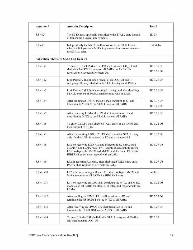
3.8.4#2 The M-TX may optionally transition to the STALL state instead
of transmitting logical idle symbols.
TD 3.4
3.8.4#3 Independently the M-RX shall transition to the STALL state
when the link partner’s M-TX implementation chooses to enter
the STALL state.
Untestable
Subsection reference: 3.8.4.1 Exit from U0
3.8.4.1#1 To enter U1, Link Partner 1 (LP1) shall initiate LGO_U1 and
shall disabled STALL entry on all PAIRs until a LXU is
received or it successfully enters U1.
TD 3.37 US
TD 3.21 DS
3.8.4.1#2 Link Partner 2 (LP2), upon receipt of an LGO_U1 and if
accepting U1 entry, shall disable STALL entry on all PAIRs.
TD 3.26 US
3.8.4.1#3 Link Partner 2 (LP2), if accepting U1 entry, and after disabling
STALL entry on all PAIRs, shall respond with an LAU.
TD 3.26 US
3.8.4.1#4 After sending an LPMA, the LP1 shall transition to U1 and
transition its M-TX to the STALL state on all PAIRs
TD 3.37 US
TD 3.21 DS
3.8.4.1#5 After receiving LPMA, the LP2 shall transition to U1 and
transition its M-TX to the STALL state on all PAIRs
TD 3.26 US
3.8.4.1#6 To enter U2, LP1 shall disable STALL entry on all PAIRs and
then transmit LGO_U2
TD 3.22 DS
3.8.4.1#7 After transmitting LGO_U2, LP1 shall re-enable STALL entry
only if either LXU is received or U2 entry is successful
TD 3.22 DS
3.8.4.1#8 LP2, on receiving LGO_U2, and if accepting U2 entry, shall
disable STALL entry on all PAIRs (until it successfully enters
U2), configure the M-TX and M-RX modules on all PAIRs for
HIBERN8 entry, then respond with an LAU.
TD 3.27 US
3.8.4.1#9 LP2, if accepting U2 entry, after disabling STALL entry on all
PAIRs, shall respond to LP1 with an LAU.
TD 3.27 US
3.8.4.1#10 LP2, after responding with an LAU, shall configure M-TX and
M-RX modules on all PAIRs for HIBERN8 entry
Implied
3.8.4.1#11 LP1, on receiving an LAU shall configure the M-TX and M-RX
modules on all PAIRs for HIBERN8 entry, and respond with an
LPMA
TD 3.22 DS
3.8.4.1#12 After sending an LPMA, LP1 shall transition to U2 and
terminate the HS-BURST on the M-TX of all PAIRs
TD 3.22 DS
3.8.4.1#13 After receiving an LPMA, LP2 shall transition to U2 and
terminate the HS-BURST on the M-TX of all PAIRs
TD 3.27 US
3.8.4.1#14 To enter U3, the DSP shall disable STALL entry on all PAIRs
and then transmit LGO_U3
TD 3.35
3/20/2014
13 SSIC Link Tests Specification [Rev 0.6]
Assertion # Assertion Description Test #
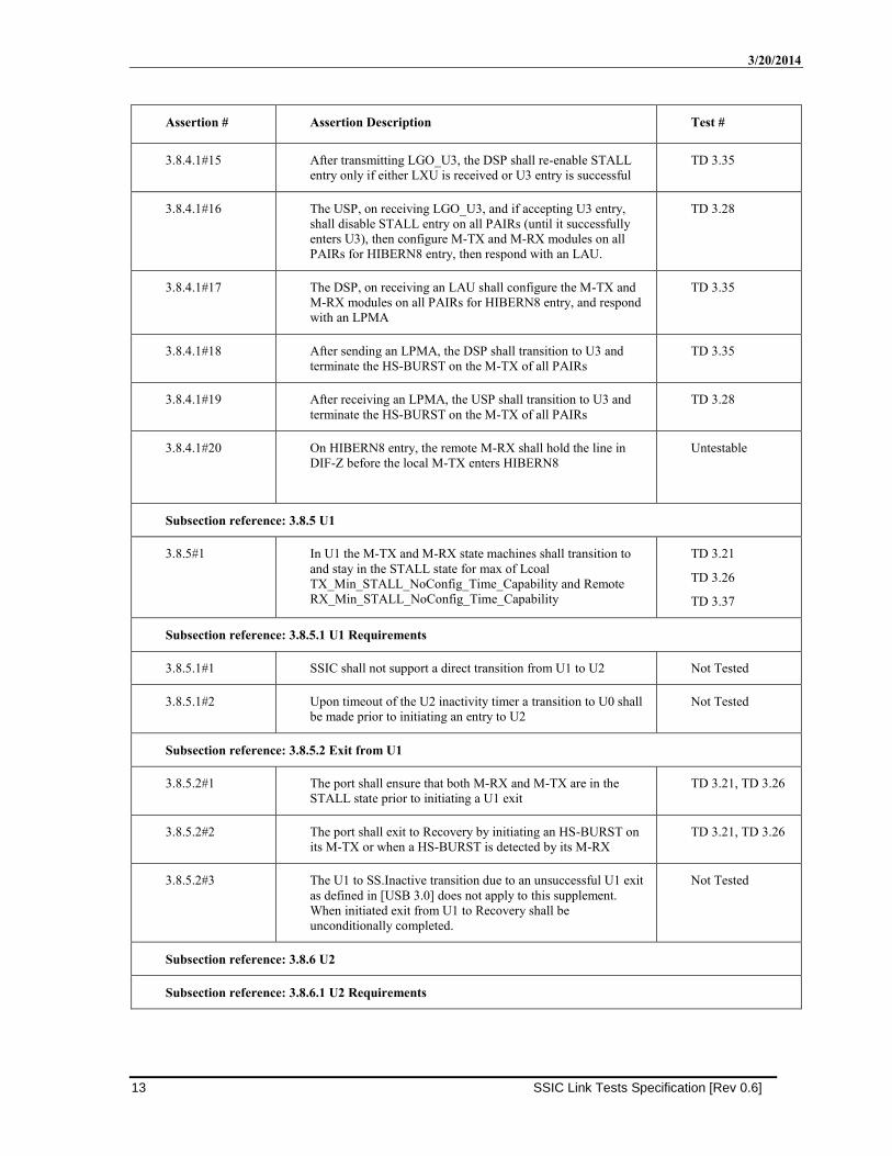
3.8.4.1#15 After transmitting LGO_U3, the DSP shall re-enable STALL
entry only if either LXU is received or U3 entry is successful
TD 3.35
3.8.4.1#16 The USP, on receiving LGO_U3, and if accepting U3 entry,
shall disable STALL entry on all PAIRs (until it successfully
enters U3), then configure M-TX and M-RX modules on all
PAIRs for HIBERN8 entry, then respond with an LAU.
TD 3.28
3.8.4.1#17 The DSP, on receiving an LAU shall configure the M-TX and
M-RX modules on all PAIRs for HIBERN8 entry, and respond
with an LPMA
TD 3.35
3.8.4.1#18 After sending an LPMA, the DSP shall transition to U3 and
terminate the HS-BURST on the M-TX of all PAIRs
TD 3.35
3.8.4.1#19 After receiving an LPMA, the USP shall transition to U3 and
terminate the HS-BURST on the M-TX of all PAIRs
TD 3.28
3.8.4.1#20 On HIBERN8 entry, the remote M-RX shall hold the line in
DIF-Z before the local M-TX enters HIBERN8
Untestable
Subsection reference: 3.8.5 U1
3.8.5#1 In U1 the M-TX and M-RX state machines shall transition to
and stay in the STALL state for max of Lcoal
TX_Min_STALL_NoConfig_Time_Capability and Remote
RX_Min_STALL_NoConfig_Time_Capability
TD 3.21
TD 3.26
TD 3.37
Subsection reference: 3.8.5.1 U1 Requirements
3.8.5.1#1 SSIC shall not support a direct transition from U1 to U2 Not Tested
3.8.5.1#2 Upon timeout of the U2 inactivity timer a transition to U0 shall
be made prior to initiating an entry to U2
Not Tested
Subsection reference: 3.8.5.2 Exit from U1
3.8.5.2#1 The port shall ensure that both M-RX and M-TX are in the
STALL state prior to initiating a U1 exit
TD 3.21, TD 3.26
3.8.5.2#2 The port shall exit to Recovery by initiating an HS-BURST on
its M-TX or when a HS-BURST is detected by its M-RX
TD 3.21, TD 3.26
3.8.5.2#3 The U1 to SS.Inactive transition due to an unsuccessful U1 exit
as defined in [USB 3.0] does not apply to this supplement.
When initiated exit from U1 to Recovery shall be
unconditionally completed.
Not Tested
Subsection reference: 3.8.6 U2
Subsection reference: 3.8.6.1 U2 Requirements
SSIC Link Tests Specification [Rev 0.6] 14
Assertion # Assertion Description Test #
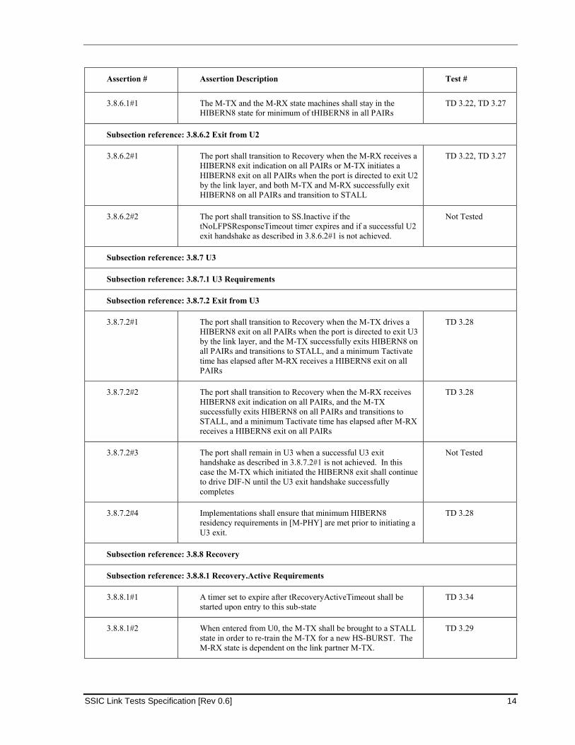
3.8.6.1#1 The M-TX and the M-RX state machines shall stay in the
HIBERN8 state for minimum of tHIBERN8 in all PAIRs
TD 3.22, TD 3.27
Subsection reference: 3.8.6.2 Exit from U2
3.8.6.2#1 The port shall transition to Recovery when the M-RX receives a
HIBERN8 exit indication on all PAIRs or M-TX initiates a
HIBERN8 exit on all PAIRs when the port is directed to exit U2
by the link layer, and both M-TX and M-RX successfully exit
HIBERN8 on all PAIRs and transition to STALL
TD 3.22, TD 3.27
3.8.6.2#2 The port shall transition to SS.Inactive if the
tNoLFPSResponseTimeout timer expires and if a successful U2
exit handshake as described in 3.8.6.2#1 is not achieved.
Not Tested
Subsection reference: 3.8.7 U3
Subsection reference: 3.8.7.1 U3 Requirements
Subsection reference: 3.8.7.2 Exit from U3
3.8.7.2#1 The port shall transition to Recovery when the M-TX drives a
HIBERN8 exit on all PAIRs when the port is directed to exit U3
by the link layer, and the M-TX successfully exits HIBERN8 on
all PAIRs and transitions to STALL, and a minimum Tactivate
time has elapsed after M-RX receives a HIBERN8 exit on all
PAIRs
TD 3.28
3.8.7.2#2 The port shall transition to Recovery when the M-RX receives
HIBERN8 exit indication on all PAIRs, and the M-TX
successfully exits HIBERN8 on all PAIRs and transitions to
STALL, and a minimum Tactivate time has elapsed after M-RX
receives a HIBERN8 exit on all PAIRs
TD 3.28
3.8.7.2#3 The port shall remain in U3 when a successful U3 exit
handshake as described in 3.8.7.2#1 is not achieved. In this
case the M-TX which initiated the HIBERN8 exit shall continue
to drive DIF-N until the U3 exit handshake successfully
completes
Not Tested
3.8.7.2#4 Implementations shall ensure that minimum HIBERN8
residency requirements in [M-PHY] are met prior to initiating a
U3 exit.
TD 3.28
Subsection reference: 3.8.8 Recovery
Subsection reference: 3.8.8.1 Recovery.Active Requirements
3.8.8.1#1 A timer set to expire after tRecoveryActiveTimeout shall be
started upon entry to this sub-state
TD 3.34
3.8.8.1#2 When entered from U0, the M-TX shall be brought to a STALL
state in order to re-train the M-TX for a new HS-BURST. The
M-RX state is dependent on the link partner M-TX.
TD 3.29
3/20/2014
15 SSIC Link Tests Specification [Rev 0.6]
Assertion # Assertion Description Test #
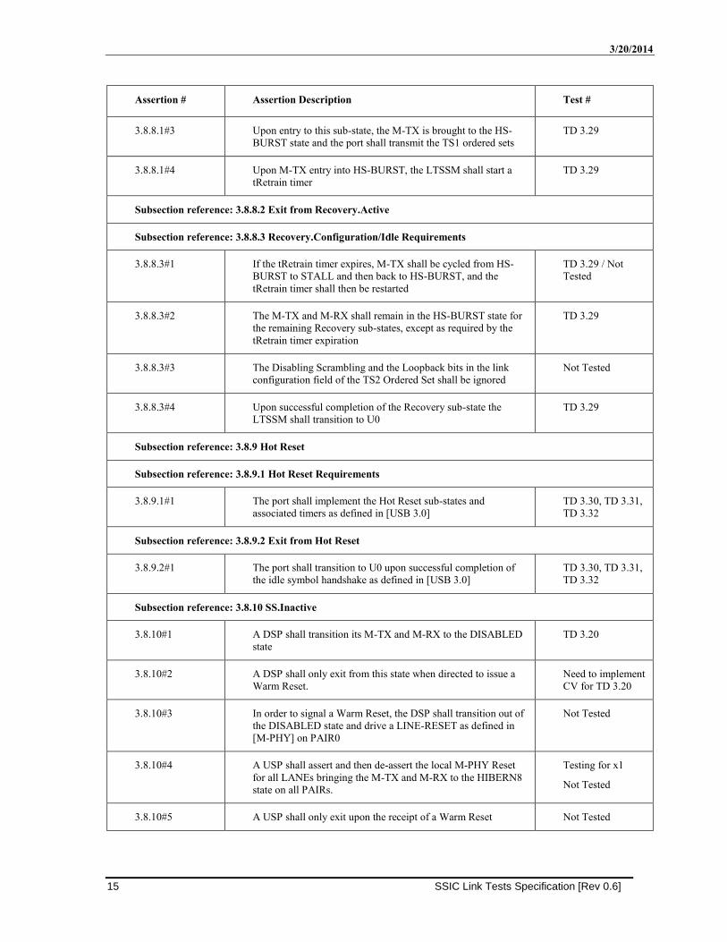
3.8.8.1#3 Upon entry to this sub-state, the M-TX is brought to the HS-
BURST state and the port shall transmit the TS1 ordered sets
TD 3.29
3.8.8.1#4 Upon M-TX entry into HS-BURST, the LTSSM shall start a
tRetrain timer
TD 3.29
Subsection reference: 3.8.8.2 Exit from Recovery.Active
Subsection reference: 3.8.8.3 Recovery.Configuration/Idle Requirements
3.8.8.3#1 If the tRetrain timer expires, M-TX shall be cycled from HS-
BURST to STALL and then back to HS-BURST, and the
tRetrain timer shall then be restarted
TD 3.29 / Not
Tested
3.8.8.3#2 The M-TX and M-RX shall remain in the HS-BURST state for
the remaining Recovery sub-states, except as required by the
tRetrain timer expiration
TD 3.29
3.8.8.3#3 The Disabling Scrambling and the Loopback bits in the link
configuration field of the TS2 Ordered Set shall be ignored
Not Tested
3.8.8.3#4 Upon successful completion of the Recovery sub-state the
LTSSM shall transition to U0
TD 3.29
Subsection reference: 3.8.9 Hot Reset
Subsection reference: 3.8.9.1 Hot Reset Requirements
3.8.9.1#1 The port shall implement the Hot Reset sub-states and
associated timers as defined in [USB 3.0]
TD 3.30, TD 3.31,
TD 3.32
Subsection reference: 3.8.9.2 Exit from Hot Reset
3.8.9.2#1 The port shall transition to U0 upon successful completion of
the idle symbol handshake as defined in [USB 3.0]
TD 3.30, TD 3.31,
TD 3.32
Subsection reference: 3.8.10 SS.Inactive
3.8.10#1 A DSP shall transition its M-TX and M-RX to the DISABLED
state
TD 3.20
3.8.10#2 A DSP shall only exit from this state when directed to issue a
Warm Reset.
Need to implement
CV for TD 3.20
3.8.10#3 In order to signal a Warm Reset, the DSP shall transition out of
the DISABLED state and drive a LINE-RESET as defined in
[M-PHY] on PAIR0
Not Tested
3.8.10#4 A USP shall assert and then de-assert the local M-PHY Reset
for all LANEs bringing the M-TX and M-RX to the HIBERN8
state on all PAIRs.
Testing for x1
Not Tested
3.8.10#5 A USP shall only exit upon the receipt of a Warm Reset Not Tested
SSIC Link Tests Specification [Rev 0.6] 16
Assertion # Assertion Description Test #
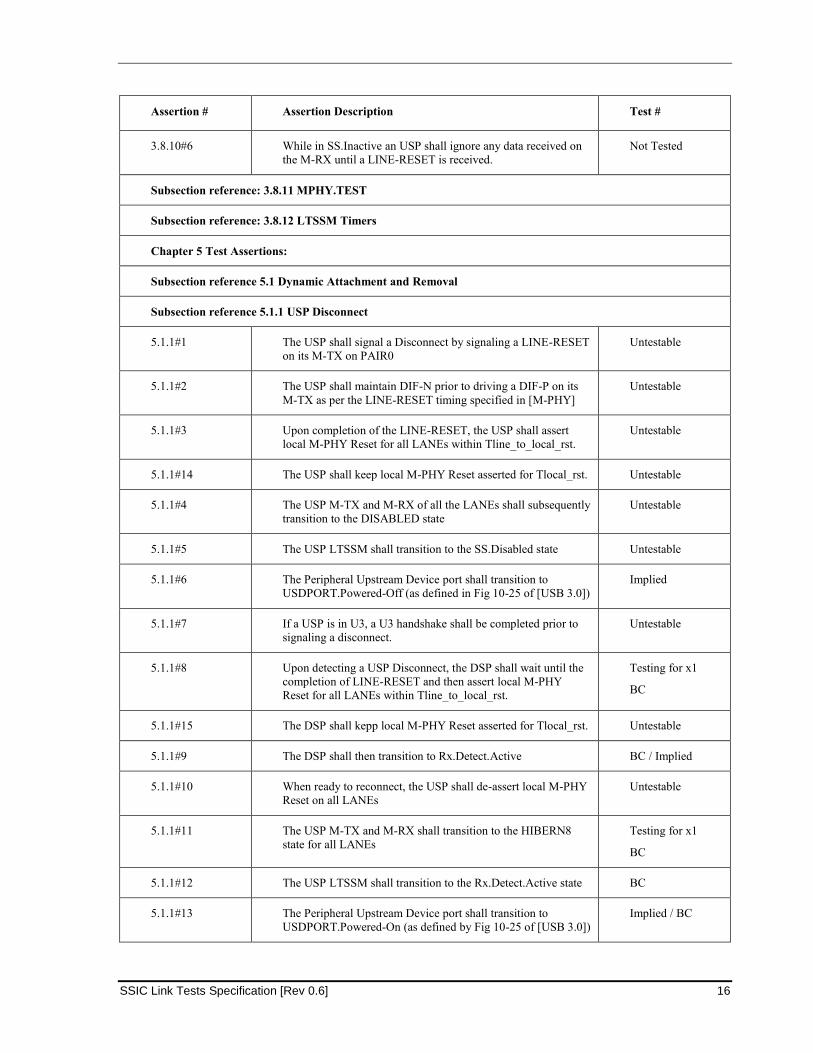
3.8.10#6 While in SS.Inactive an USP shall ignore any data received on
the M-RX until a LINE-RESET is received.
Not Tested
Subsection reference: 3.8.11 MPHY.TEST
Subsection reference: 3.8.12 LTSSM Timers
Chapter 5 Test Assertions:
Subsection reference 5.1 Dynamic Attachment and Removal
Subsection reference 5.1.1 USP Disconnect
5.1.1#1 The USP shall signal a Disconnect by signaling a LINE-RESET
on its M-TX on PAIR0
Untestable
5.1.1#2 The USP shall maintain DIF-N prior to driving a DIF-P on its
M-TX as per the LINE-RESET timing specified in [M-PHY]
Untestable
5.1.1#3 Upon completion of the LINE-RESET, the USP shall assert
local M-PHY Reset for all LANEs within Tline_to_local_rst.
Untestable
5.1.1#14 The USP shall keep local M-PHY Reset asserted for Tlocal_rst. Untestable
5.1.1#4 The USP M-TX and M-RX of all the LANEs shall subsequently
transition to the DISABLED state
Untestable
5.1.1#5 The USP LTSSM shall transition to the SS.Disabled state Untestable
5.1.1#6 The Peripheral Upstream Device port shall transition to
USDPORT.Powered-Off (as defined in Fig 10-25 of [USB 3.0])
Implied
5.1.1#7 If a USP is in U3, a U3 handshake shall be completed prior to
signaling a disconnect.
Untestable
5.1.1#8 Upon detecting a USP Disconnect, the DSP shall wait until the
completion of LINE-RESET and then assert local M-PHY
Reset for all LANEs within Tline_to_local_rst.
Testing for x1
BC
5.1.1#15 The DSP shall kepp local M-PHY Reset asserted for Tlocal_rst. Untestable
5.1.1#9 The DSP shall then transition to Rx.Detect.Active BC / Implied
5.1.1#10 When ready to reconnect, the USP shall de-assert local M-PHY
Reset on all LANEs
Untestable
5.1.1#11 The USP M-TX and M-RX shall transition to the HIBERN8
state for all LANEs
Testing for x1
BC
5.1.1#12 The USP LTSSM shall transition to the Rx.Detect.Active state BC
5.1.1#13 The Peripheral Upstream Device port shall transition to
USDPORT.Powered-On (as defined by Fig 10-25 of [USB 3.0])
Implied / BC
3/20/2014
17 SSIC Link Tests Specification [Rev 0.6]
Assertion # Assertion Description Test #
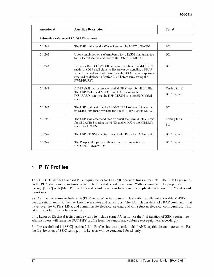
Subsection reference 5.1.2 DSP Disconnect
5.1.2#1 The DSP shall signal a Warm Reset on the M-TX of PAIR0 BC
5.1.2#2 Upon completion of a Warm Reset, the LTSSM shall transition
to Rx.Detect.Active and then to Rx.Detect.LS-MODE
BC
5.1.2#3 In the Rx.Detect.LS-MODE sub-state, while in PWM-BURST
mode, the DSP shall signal a disconnect by signaling a RRAP
write command and shall ensure a valid RRAP write response is
received as defined in Section 2.5.2 before terminating the
PWM-BURST
BC
5.1.2#4 A DSP shall then assert the local M-PHY reset for all LANEs.
The DSP M-TX and M-RX of all LANEs are in the
DISABLED state, and the DSP LTSSM is in the SS.Disabled
state
Testing for x1
BC / Implied
5.1.2#5 The USP shall wait for the PWM-BURST to be terminated on
its M-RX, and then terminate the PWM-BURST on its M-TX.
BC
5.1.2#6 The USP shall assert and then de-assert the local M-PHY Reset
for all LANEs bringing the M-TX and M-RX to the HIBERN8
state on all PAIRs
Testing for x1
BC
5.1.2#7 The USP LTSSM shall transition to the Rx.Detect.Active state BC / Implied
5.1.2#8 The Peripheral Upstream Device port shall transition to
USDPORT.Powered-On
BC / Implied
4 PHY Profiles
The [USB 3.0] defines standard PHY requirements for USB 3.0 receivers, transmitters, etc. The Link Layer relies
on the PHY states and transitions to facilitate Link states and transitions. With a change in PHY properties
through [SSIC] with [M-PHY] the Link states and transitions have a more complicated relation to PHY states and
transitions.
SSIC implementations include a PA (PHY Adapter) to transparently deal with the different allowable M-PHY
configurations and map them to Link Layer states and transitions. The PA includes defined RRAP commands that
travel over the M-PHY LINK and communicate electrical settings and will setup an electrical configuration. This
takes places before any link training.
Link Layer or Electrical testing may expand to include some PA tests. For the first iteration of SSIC testing, test
administrators will learn the DUT PHY profile from the vendor and calibrate test equipment accordingly.
Profiles are defined in [SSIC] section 2.2.1. Profiles indicate speed, multi-LANE capabilities and rate series. For
the first iteration of SSIC testing, l = 1, i.e. tests will be conducted for x1 only.
SSIC Link Tests Specification [Rev 0.6] 18
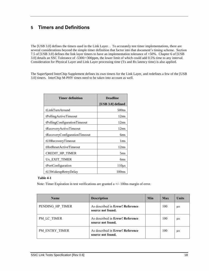
5 Timers and Definitions
The [USB 3.0] defines the timers used in the Link Layer. . To accurately test timer implementations, there are
several considerations beyond the simple timer definition that factor into that document’s timing scheme. Section
7.5 of [USB 3.0] defines the link layer timers to have an implementation tolerance of +50%. Chapter 6 of [USB
3.0] details an SSC Tolerance of -5300/+300ppm, the lower limit of which could add 0.5% time to any interval.
Consideration for Physical Layer and Link Layer processing time (Tx and Rx latency time) is also applied.
The SuperSpeed InterChip Supplement defines its own timers for the Link Layer, and redefines a few of the [USB
3.0] timers. InterChip M-PHY times need to be taken into account as well.
Timer definition Deadline
[USB 3.0] defined
tLinkTurnAround 500ns
tPollingActiveTimeout 12ms
tPollingConfigurationTimeout 12ms
tRecoveryActiveTimeout 12ms
tRecoveryConfigurationTimeout 6ms
tU0RecoveryTimeout 1ms
tHotResetActiveTimeout 12ms
CREDIT_HP_TIMER 5ms
Ux_EXIT_TIMER 6ms
tPortConfiguration 110μs
tU3WakeupRetryDelay 100ms
Table 4-1
Note: Timer Expiration in test verifications are granted a +/- 100ns margin of error.
Name Description Min Max Units
PENDING_HP_TIMER As described in Error! Reference
source not found.
100 µs
PM_LC_TIMER As described in Error! Reference
source not found.
100 µs
PM_ENTRY_TIMER As described in Error! Reference
source not found.
100 µs
3/20/2014
19 SSIC Link Tests Specification [Rev 0.6]
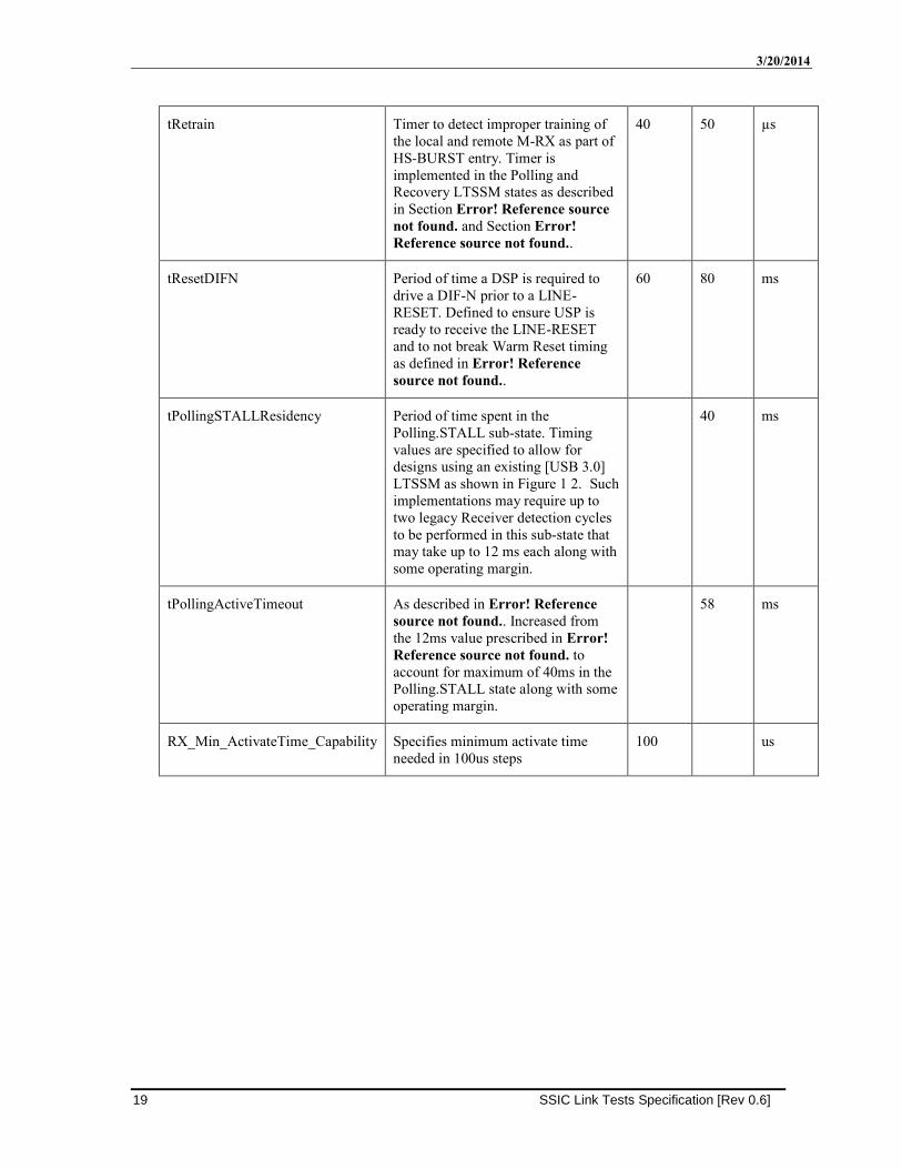
tRetrain Timer to detect improper training of
the local and remote M-RX as part of
HS-BURST entry. Timer is
implemented in the Polling and
Recovery LTSSM states as described
in Section Error! Reference source
not found. and Section Error!
Reference source not found..
40 50 µs
tResetDIFN Period of time a DSP is required to
drive a DIF-N prior to a LINE-
RESET. Defined to ensure USP is
ready to receive the LINE-RESET
and to not break Warm Reset timing
as defined in Error! Reference
source not found..
60 80 ms
tPollingSTALLResidency Period of time spent in the
Polling.STALL sub-state. Timing
values are specified to allow for
designs using an existing [USB 3.0]
LTSSM as shown in Figure 1 2. Such
implementations may require up to
two legacy Receiver detection cycles
to be performed in this sub-state that
may take up to 12 ms each along with
some operating margin.
40 ms
tPollingActiveTimeout As described in Error! Reference
source not found.. Increased from
the 12ms value prescribed in Error!
Reference source not found. to
account for maximum of 40ms in the
Polling.STALL state along with some
operating margin.
58 ms
RX_Min_ActivateTime_Capability Specifies minimum activate time
needed in 100us steps
100 us
SSIC Link Tests Specification [Rev 0.6] 20
6 SSIC Link Test Descriptions
6.1 Link Initialization Sequence
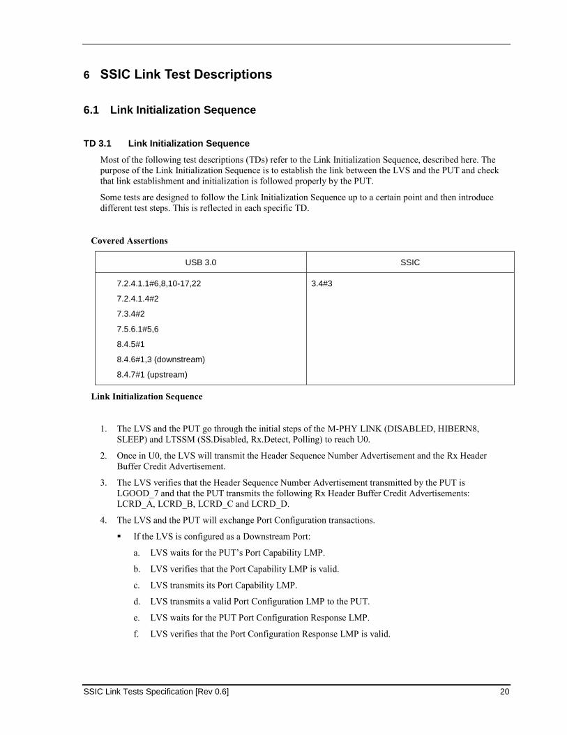
TD 3.1 Link Initialization Sequence
Most of the following test descriptions (TDs) refer to the Link Initialization Sequence, described here. The
purpose of the Link Initialization Sequence is to establish the link between the LVS and the PUT and check
that link establishment and initialization is followed properly by the PUT.
Some tests are designed to follow the Link Initialization Sequence up to a certain point and then introduce
different test steps. This is reflected in each specific TD.
Covered Assertions
USB 3.0 SSIC
7.2.4.1.1#6,8,10-17,22
7.2.4.1.4#2
7.3.4#2
7.5.6.1#5,6
8.4.5#1
8.4.6#1,3 (downstream)
8.4.7#1 (upstream)
3.4#3
Link Initialization Sequence
1. The LVS and the PUT go through the initial steps of the M-PHY LINK (DISABLED, HIBERN8,
SLEEP) and LTSSM (SS.Disabled, Rx.Detect, Polling) to reach U0.
2. Once in U0, the LVS will transmit the Header Sequence Number Advertisement and the Rx Header
Buffer Credit Advertisement.
3. The LVS verifies that the Header Sequence Number Advertisement transmitted by the PUT is
LGOOD_7 and that the PUT transmits the following Rx Header Buffer Credit Advertisements:
LCRD_A, LCRD_B, LCRD_C and LCRD_D.
4. The LVS and the PUT will exchange Port Configuration transactions.
If the LVS is configured as a Downstream Port:
a. LVS waits for the PUT’s Port Capability LMP.
b. LVS verifies that the Port Capability LMP is valid.
c. LVS transmits its Port Capability LMP.
d. LVS transmits a valid Port Configuration LMP to the PUT.
e. LVS waits for the PUT Port Configuration Response LMP.
f. LVS verifies that the Port Configuration Response LMP is valid.
3/20/2014
21 SSIC Link Tests Specification [Rev 0.6]
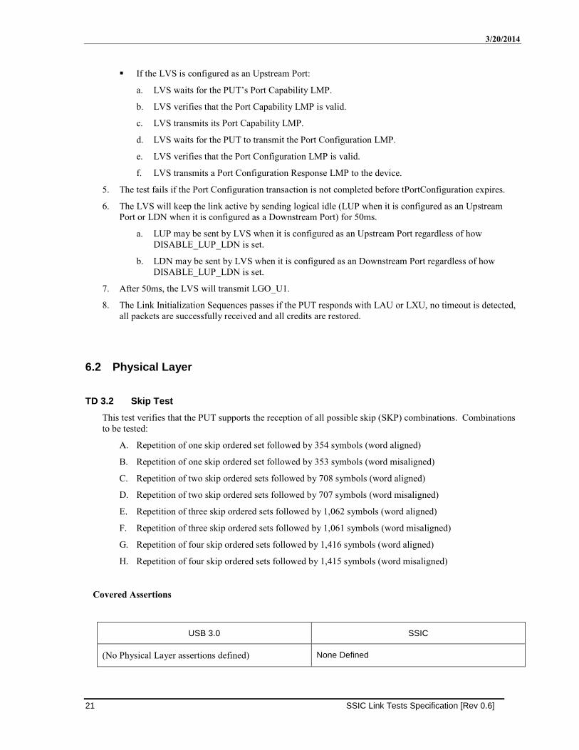
If the LVS is configured as an Upstream Port:
a. LVS waits for the PUT’s Port Capability LMP.
b. LVS verifies that the Port Capability LMP is valid.
c. LVS transmits its Port Capability LMP.
d. LVS waits for the PUT to transmit the Port Configuration LMP.
e. LVS verifies that the Port Configuration LMP is valid.
f. LVS transmits a Port Configuration Response LMP to the device.
5. The test fails if the Port Configuration transaction is not completed before tPortConfiguration expires.
6. The LVS will keep the link active by sending logical idle (LUP when it is configured as an Upstream
Port or LDN when it is configured as a Downstream Port) for 50ms.
a. LUP may be sent by LVS when it is configured as an Upstream Port regardless of how
DISABLE_LUP_LDN is set.
b. LDN may be sent by LVS when it is configured as an Downstream Port regardless of how
DISABLE_LUP_LDN is set.
7. After 50ms, the LVS will transmit LGO_U1.
8. The Link Initialization Sequences passes if the PUT responds with LAU or LXU, no timeout is detected,
all packets are successfully received and all credits are restored.
6.2 Physical Layer
TD 3.2 Skip Test
This test verifies that the PUT supports the reception of all possible skip (SKP) combinations. Combinations
to be tested:
A. Repetition of one skip ordered set followed by 354 symbols (word aligned)
B. Repetition of one skip ordered set followed by 353 symbols (word misaligned)
C. Repetition of two skip ordered sets followed by 708 symbols (word aligned)
D. Repetition of two skip ordered sets followed by 707 symbols (word misaligned)
E. Repetition of three skip ordered sets followed by 1,062 symbols (word aligned)
F. Repetition of three skip ordered sets followed by 1,061 symbols (word misaligned)
G. Repetition of four skip ordered sets followed by 1,416 symbols (word aligned)
H. Repetition of four skip ordered sets followed by 1,415 symbols (word misaligned)
Covered Assertions
USB 3.0 SSIC
(No Physical Layer assertions defined) None Defined
SSIC Link Tests Specification [Rev 0.6] 22
Overview of Test Steps
1. Do steps 1 to 4 of the Link Initialization Sequence.
2. The LVS will keep the link active by sending Link Pollings (LUP when it is configured as an Upstream
Port or LDN when it is configured as a Downstream Port) for 50ms. Skips will be generated according
to the first pattern described above.
3. Continue to Step 6 of the Link Initialization Sequence.
4. Repeat the steps with the other skip patterns listed above.
TD 3.3 Elasticity Buffer Test
This test verifies that the PUT’s elasticity buffer supports the required frequency range, from -300 to 300ppm.
Covered Assertions
USB 3.0 SSIC
(No Physical Layer assertions defined) None Defined
Overview of Test Steps
1. Configure the LVS with a clock of -300ppm.
2. Bring the link to U0 using the Link Initialization Sequence.
3. The test passes if the Link Initialization Sequence passes.
4. Repeat the above steps with a clock of +300ppm.
6.3 Link Layer
TD 3.4 Link Bring-up Test
This test verifies that the Link Verification System (LVS) and the Port under Test (PUT) can reach U0
successfully.
Covered Assertions
USB 3.0 SSIC
7.2.4.1.1#6,8,10-17,22
7.2.4.1.4#2
7.3.4#2
7.5.6.1#5,6
8.4.5#1
8.4.6#1,3 (downstream)
8.4.7#1 (upstream)
3.8.2.3#1,2,3
3.8.2.4#1,2
3.8.2.6#3,4
3.8.3.1#2
3.8.3.2#2
3.8.3.3#1,2,5
3.8.4#1,2
Overview of Test Steps
1. The LVS starts the link process.
3/20/2014
23 SSIC Link Tests Specification [Rev 0.6]
If the LVS is configured as a Downstream Port:
a. Power is asserted for the test.
b. The LVS moves from UNPOWERED to DISABLED to HIBERN8 to SLEEP in accordance
with [M-PHY].
c. The PUT should move from UNPOWERED to DISABLED when it receives a RESET and
to HIBERN8 when RESET is de-asserted.
i. Before PUT RESET, the LVS verifies that LINE voltages do not exceed the safe
operation voltage window, VPIN.
d. The PUT should move from SS.Disabled to Rx.Detect.Active when it detects DIF-N on its
M-RX signaling a far-end transition to SLEEP.
e. The LVS detects DIF-N on its M-RX, waits for Tactivate and transitions to Rx.Detect.LS-
MODE.
If the LVS is configured as an Upstream Port:
a. Power is asserted for the test.
b. The PUT should move from UNPOWERED to DISABLED when it receives the RESET
and upon de-assertion of RESET should move to HIBERN8 to SLEEP in accordance with
[M-PHY].
c. When RESET is de-asserted, the PUT should transition from SS.Disabled to
Rx.Detect.Active.
d. Upon detecting DIF-N on its M-RX, the LVS transitions to SLEEP and Rx.Detect.LS-
MODE
e. The PUT should move from Rx.Detect.Active to Rx.Detect.LS-MODE
2. The test fails if the PUT does not transition to Rx.Detect.LS-MODE.
3. The LVS executes an RCT (Re-Configuration Trigger).
4. The test fails if the PUT does not transition to Polling after RX_Min_ActivateTime_Capability.
5. The LVS fails if the PUT is not in the STALL state.
6. The LVS starts tRetrain timer. If the tRetrain timer expires during steps 8 – 13, transition LVS to
STALL and return to this step (7).
7. The LVS M-TX transitions from STALL to HS-BURST.
8. The LVS fails if the PUT does not transition to Polling.Active within tPollingSTALLResidency.
9. The LVS transmits TS1 ordered sets and waits to receive eight consecutive and identical TS1 or TS2
ordered sets from the PUT.
10. The test fails if any of the following occur:
a. The PUT does not transmit TS1 ordered sets.
b. The PUT transmits TS2s before the LVS sends eight consecutive and identical TS1s or TS2s.
c. The PUT interrupts a TS1 ordered set to transmit a SKP ordered set (between TS1 ordered sets is
OK).
d. The PUT transmits Idle Symbols or any other Packet.
e. The PUT continues to transmit TS1 ordered sets after tPollingActiveTimeout expires.
11. The LVS transmits TS2 ordered sets and readies to complete the Polling.Configuration handshake.
12. The test fails if any of the following occur:
SSIC Link Tests Specification [Rev 0.6] 24
a. The PUT does not transmit at least sixteen consecutiveTS2 ordered sets after receiving one TS2
ordered set.
b. The PUT sends Idle symbols before the LVS sends at least eight consecutive TS2 ordered sets.
c. The PUT interrupts transmission of a TS2 ordered set to transmit a SKP ordered set (between TS2
ordered sets is OK).
d. The PUT continues to transmit TS2 ordered sets after tPollingConfigurationTimeout expires.
e. The PUT transmits any other Packets.
13. The LVS transmits Idle symbols.
14. The test fails if any of the following occur:
a. The PUT does not transmit sixteen Idle Symbols after TS2 ordered sets.
b. The PUT transmits the Header Sequence Number Advertisement and the Rx Header Buffer Credit
Advertisement before the LVS transmits 8 Idle symbols.
c. The PUT enters recovery after Idle symbols have been exchanged.
d. Upon entering U0, the PUT does not transmit the Header Sequence Number Advertisement and the
Rx Header Buffer Credit Advertisement before their respective timeouts, PENDING_HP_TIMER
and CREDIT_HP_TIMER, expire.
15. The LVS and PUT continue the test with the Link Initialization Sequence starting at step two.
TD 3.5 Link Commands Framings Robustness Test
This test verifies that the PUT can tolerate link commands having one symbol error in the LCSTART
framing. Here are the combinations to be tested:
A. ERR SLC SLC EPF
B. SLC ERR SLC EPF
C. SLC SLC ERR EPF
D. SLC SLC SLC ERR
The Port Configuration transaction will be used for this purpose.
Covered Assertions
USB 3.0 SSIC
7.3.4#1,2 None Defined
Overview of Test Steps
1. Perform the Link Initialization Sequence, but transmit all LCRD_X with an error in the first LCSTART
symbol.
2. The test passes if the Link Initialization Sequence passes.
3. Repeat the above steps with an error in the second, third, and fourth LCSTART symbols as shown above.
3/20/2014
25 SSIC Link Tests Specification [Rev 0.6]
TD 3.6 Link Commands CRC-5 Robustness Test
This test verifies that the PUT will ignore link commands with a CRC-5 error, even if only one of the Link
Command Words has a CRC-5 error. The Port Configuration transaction will be used for this purpose.
The tested CRC-5 error robustness conditions are:
A. Incorrect CRC-5 in first Link Command Word
B. Incorrect CRC-5 in second Link Command Word
C. Both Link Command Words have an incorrect CRC-5.
Covered Assertions
USB 3.0 SSIC
7.3.4#2 None Defined
Overview of Test Steps
1. Perform the Link Initialization Sequence but transmit all LCRD_X with condition A above.
2. The test passes if the PUT enters recovery when CREDIT_HP_TIMER expires.
3. Repeat the above steps for each condition listed above. .
TD 3.7 Invalid Link Commands Test
This test verifies that the PUT will ignore Link Commands with link command information in the first LCW
not the same as link command information in the second LCW, and both pass the CRC5 check.
Covered Assertions
USB 3.0 SSIC
7.3.4#2 None Defined
Overview of Test Steps
1. Do steps 1 to 5 of the Link Initialization Sequence.
2. The LVS sends a link command with LGO_U1 in the first LCW and LGO_U2 in the second LCW, with
good CRC-5 calculations on both.
3. The test fails if the PUT responds with an LAU or LXU.
4. Continue to Step 6 of the Link Initialization Sequence.
SSIC Link Tests Specification [Rev 0.6] 26
TD 3.8 Header Packet Framing Robustness Test
This test verifies that the PUT does not invalidate header packets having one symbol error in the HPSTART
framing. The combinations to be tested:
A. ERR SHP SHP EPF
B. SHP ERR SHP EPF
C. SHP SHP ERR EPF
D. SHP SHP SHP ERR
The Port Configuration transaction will be used for this purpose.
Covered Assertions
USB 3.0 SSIC
7.2.4.1.4#1 None Defined
Overview of Test Steps
1. Perform the Link Initialization Sequence, but transmit all Header Packets with an error in the first
HPSTART symbol.
2. The test passes if the Link Initialization Sequence passes.
3. Repeat the above steps with an error in the second, third, and fourth HPSTART symbols, as shown above.
TD 3.9 Data Payload Packet Framing Robustness Test
This test verifies that the PUT does not invalidate data payload packets having a single character framing
error in DPPSTART and DPPEND. The combinations to be tested:
A. ERR SDP SDP EPF
B. SDP ERR SDP EPF
C. SDP SDP ERR EPF
D. SDP SDP SDP ERR
E. ERR END END EPF
F. END ERR END EPF
G. END END ERR EPF
H. END END END ERR
When the LVS is a Downstream Port, it will place framing errors on Setup DP Packets.
When the LVS is an Upstream Port, it will reply to the GetDeviceDescriptor request with a DPP containing
framing errors.
3/20/2014
27 SSIC Link Tests Specification [Rev 0.6]
Covered Assertions
USB 3.0 SSIC
7.2.4.1.6#1,2 None Defined
Overview of Test Steps
1. Perform the Link Initialization Sequence.
2. At this stage the Downstream Port is expected to issue a GetDeviceDescriptor request.
If the LVS is configured as an Upstream Port:
a. The LVS prompts the test operator to have the PUT send a GetDeviceDescriptor
request through USB30CV and then press “OK”.
b. The test fails if no GetDeviceDescriptor request is received and the test operator has
pressed “OK”.
c. When the LVS receives a GetDeviceDescriptor request, it closes the prompt. The LVS
will respond to the request with a DPP containing the Device Descriptor data which
includes the first framing error listed above.
If the LVS is configured as a Downstream Port, it will issue a GetDeviceDescriptor request, but
will send the SETUP DP with the first framing error listed above.
3. The test fails if the data exchange fails on the protocol level.
4. Continue to Step 6 of the Link Initialization Sequence.
5. Repeat for each condition listed above.
TD 3.10 RX Header Packet Retransmission Test
This test verifies that the PUT will send an LBAD if an invalid header packet is received, and that the
retransmission will be correctly handled.
The tested conditions invalidating a header packet are:
A. Incorrect CRC-16
B. Incorrect CRC-5
C. K28.0 Reserved K-symbol in HP data
D. K28.2 SDP symbol in HP data
E. K28.3 EDB symbol in HP data
F. K28.4 SUB symbol in HP data
G. K28.6 Reserved K-symbol in HP data
H. K28.7 Reserved K-symbol in HP data
I. K27.7 SHP symbol in HP data
J. K29.7 END symbol in HP data
K. K30.7 SLC symbol in HP data
L. K23.7 EPF symbol in HP data
SSIC Link Tests Specification [Rev 0.6] 28
Each of the conditions C – J are tested in the following positions, one case at a time:
1. Position 2: SHP SHP SHP EPF DX.X KX.X DX.X DX.X
2. Position 5: SHP SHP SHP EPF DX.X DX.X DX.X DX.X KX.X
Covered Assertions
USB 3.0 SSIC
7.2.4.1.4#3,4 None Defined
Overview of Test Steps
1. Do steps 1 to 3 of the Link Initialization Sequence.
2. The LVS and the PUT will exchange Port Configuration transactions, but the first packet sent by the
LVS will be invalid.
If the LVS is configured as a Downstream Port:
a. The LVS waits for the PUT’s Port Capability LMP.
b. LVS verifies that the Port Capability LMP is valid.
c. LVS transmits its Port Capability LMP with the first invalid condition listed above.
d. LVS verifies that the PUT replies with an LBAD.
e. LVS transmits a LRTY and then retransmits the packet.
f. LVS transmits the Port Configuration LMP.
g. LVS waits for the PUT’s Port Configuration Response LMP.
h. LVS verifies the PUT’s Port Configuration Response LMP.
If the LVS is configured as an Upstream Port:
a. LVS waits for the PUT’s Port Capability LMP.
b. LVS verifies that the Port Capability LMP is valid.
c. LVS transmits its Port Capability LMP with the first invalid condition listed above.
d. LVS verifies the PUT replies with an LBAD.
e. LVS transmits a LRTY and then retransmits the packet.
f. LVS waits for the PUT’s Port Configuration LMP.
g. LVS verifies the PUT’s Port Configuration LMP.
h. LVS transmits its Port Configuration Response LMP.
3. Continue to Step 6 of the Link Initialization Sequence.
4. Repeat the above steps for each of the invalid conditions listed above.
3/20/2014
29 SSIC Link Tests Specification [Rev 0.6]
TD 3.11 TX Header Packet Retransmission Test
This test verifies that the PUT will correctly retransmit a header packet on receipt of an LBAD.
Covered Assertions
USB 3.0 SSIC
7.2.4.1.3#1,2 None Defined
Overview of Test Steps
1. Do steps 1 to 3 of the Link Initialization Sequence.
2. The LVS and the PUT will exchange the Port Configuration transaction, but in this case the LVS will
respond to the first packet sent by the PUT with an LBAD.
If the LVS is configured as a Downstream Port:
a. LVS waits for the PUT’s Port Capability LMP.
b. LVS verifies that the Port Capability LMP is valid.
c. LVS responds to the PUT with an LBAD.
d. LVS waits for the PUT to transmit an LRTY.
e. LVS waits for the retransmitted packet.
f. LVS verifies that the retransmitted packet is the same as the first packet sent by the device.
g. LVS transmits its Port Capability LMP and Port Configuration LMP.
h. LVS waits for the PUT Port Configuration Response LMP.
i. LVS verifies the PUT’s Port Configuration Response LMP.
If the LVS is configured as an Upstream Port:
a. LVS waits for the PUT’s Port Capability LMP.
b. LVS verifies that the Port Capability LMP is valid.
c. LVS transmits its Port Capability LMP.
d. LVS responds to the PUT with an LBAD.
e. LVS waits for the PUT to transmit an LRTY.
f. LVS waits for the retransmitted packet.
g. LVS verifies that the retransmitted packet is the same as the first packet sent by the device.
h. LVS waits for the PUT’s Port Configuration LMP.
i. LVS verifies that the Port Configuration LMP is valid.
j. LVS transmits its Port Configuration Response LMP.
3. Continue to Step 6 of the Link Initialization Sequence.
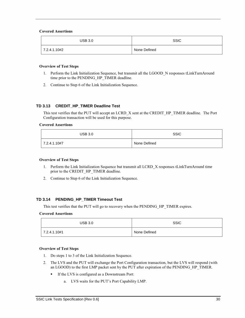
TD 3.12 PENDING_HP_TIMER Deadline Test
This test verifies that the PUT will accept an LGOOD_N sent at the PENDING_HP_TIMER deadline. The
Port Configuration transaction will be used for this purpose.
SSIC Link Tests Specification [Rev 0.6] 30
Covered Assertions
USB 3.0 SSIC
7.2.4.1.10#2 None Defined
Overview of Test Steps
1. Perform the Link Initialization Sequence, but transmit all the LGOOD_N responses tLinkTurnAround
time prior to the PENDING_HP_TIMER deadline.
2. Continue to Step 6 of the Link Initialization Sequence.
TD 3.13 CREDIT_HP_TIMER Deadline Test
This test verifies that the PUT will accept an LCRD_X sent at the CREDIT_HP_TIMER deadline. The Port
Configuration transaction will be used for this purpose.
Covered Assertions
USB 3.0 SSIC
7.2.4.1.10#7 None Defined
Overview of Test Steps
1. Perform the Link Initialization Sequence but transmit all LCRD_X responses tLinkTurnAround time
prior to the CREDIT_HP_TIMER deadline.
2. Continue to Step 6 of the Link Initialization Sequence.
TD 3.14 PENDING_HP_TIMER Timeout Test
This test verifies that the PUT will go to recovery when the PENDING_HP_TIMER expires.
Covered Assertions
USB 3.0 SSIC
7.2.4.1.10#1 None Defined
Overview of Test Steps
1. Do steps 1 to 3 of the Link Initialization Sequence.
2. The LVS and the PUT will exchange the Port Configuration transaction, but the LVS will respond (with
an LGOOD) to the first LMP packet sent by the PUT after expiration of the PENDING_HP_TIMER.
If the LVS is configured as a Downstream Port:
a. LVS waits for the PUT’s Port Capability LMP.
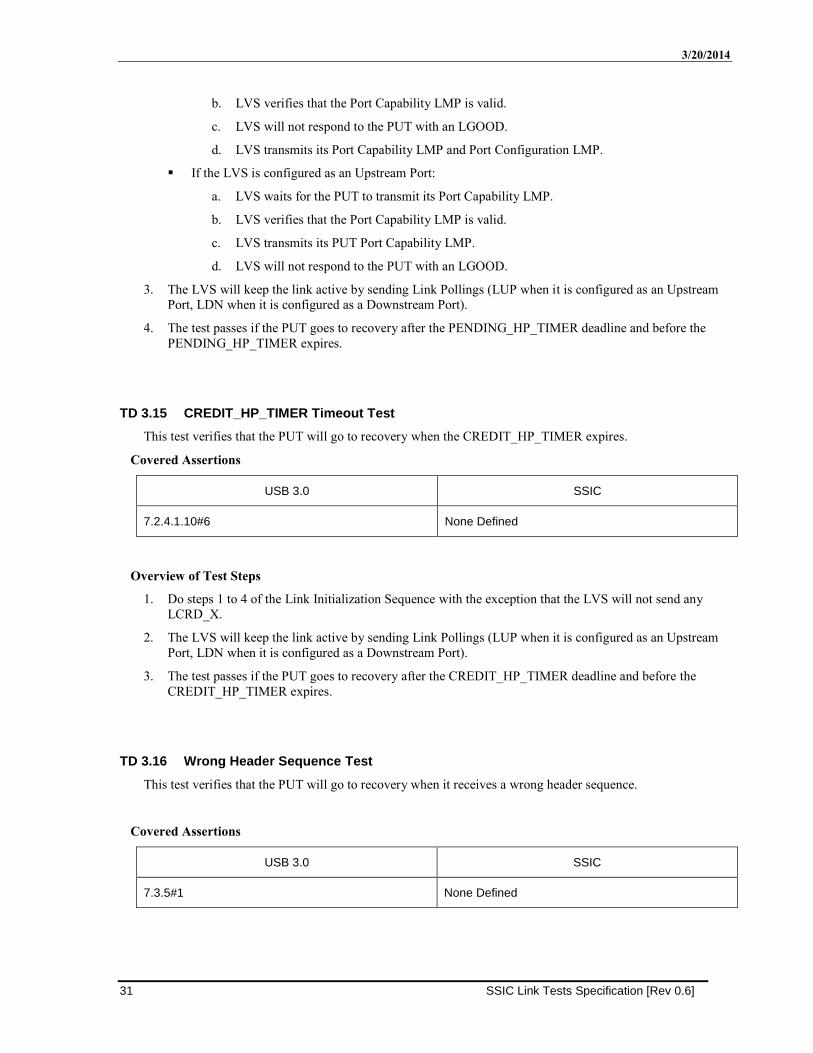
3/20/2014
31 SSIC Link Tests Specification [Rev 0.6]
b. LVS verifies that the Port Capability LMP is valid.
c. LVS will not respond to the PUT with an LGOOD.
d. LVS transmits its Port Capability LMP and Port Configuration LMP.
If the LVS is configured as an Upstream Port:
a. LVS waits for the PUT to transmit its Port Capability LMP.
b. LVS verifies that the Port Capability LMP is valid.
c. LVS transmits its PUT Port Capability LMP.
d. LVS will not respond to the PUT with an LGOOD.
3. The LVS will keep the link active by sending Link Pollings (LUP when it is configured as an Upstream
Port, LDN when it is configured as a Downstream Port).
4. The test passes if the PUT goes to recovery after the PENDING_HP_TIMER deadline and before the
PENDING_HP_TIMER expires.
TD 3.15 CREDIT_HP_TIMER Timeout Test
This test verifies that the PUT will go to recovery when the CREDIT_HP_TIMER expires.
Covered Assertions
USB 3.0 SSIC
7.2.4.1.10#6 None Defined
Overview of Test Steps
1. Do steps 1 to 4 of the Link Initialization Sequence with the exception that the LVS will not send any
LCRD_X.
2. The LVS will keep the link active by sending Link Pollings (LUP when it is configured as an Upstream
Port, LDN when it is configured as a Downstream Port).
3. The test passes if the PUT goes to recovery after the CREDIT_HP_TIMER deadline and before the
CREDIT_HP_TIMER expires.
TD 3.16 Wrong Header Sequence Test
This test verifies that the PUT will go to recovery when it receives a wrong header sequence.
Covered Assertions
USB 3.0 SSIC
7.3.5#1 None Defined
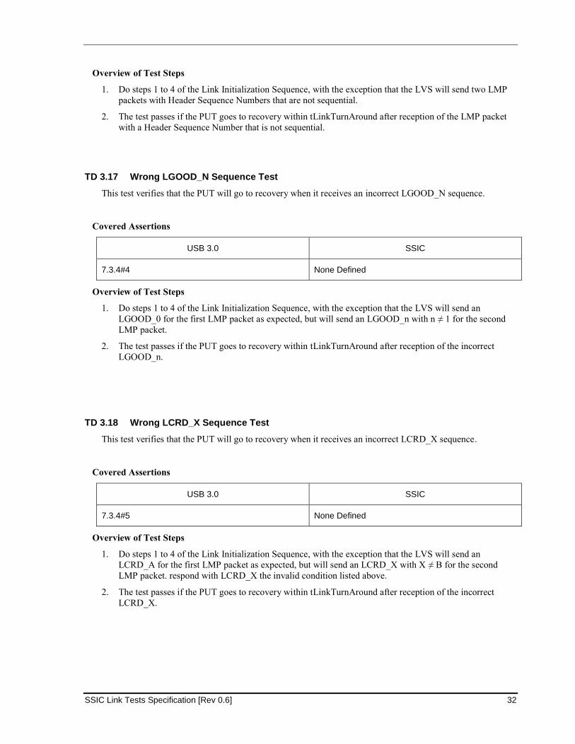
SSIC Link Tests Specification [Rev 0.6] 32
Overview of Test Steps
1. Do steps 1 to 4 of the Link Initialization Sequence, with the exception that the LVS will send two LMP
packets with Header Sequence Numbers that are not sequential.
2. The test passes if the PUT goes to recovery within tLinkTurnAround after reception of the LMP packet
with a Header Sequence Number that is not sequential.
TD 3.17 Wrong LGOOD_N Sequence Test
This test verifies that the PUT will go to recovery when it receives an incorrect LGOOD_N sequence.
Covered Assertions
USB 3.0 SSIC
7.3.4#4 None Defined
Overview of Test Steps
1. Do steps 1 to 4 of the Link Initialization Sequence, with the exception that the LVS will send an
LGOOD_0 for the first LMP packet as expected, but will send an LGOOD_n with n ≠ 1 for the second
LMP packet.
2. The test passes if the PUT goes to recovery within tLinkTurnAround after reception of the incorrect
LGOOD_n.
TD 3.18 Wrong LCRD_X Sequence Test
This test verifies that the PUT will go to recovery when it receives an incorrect LCRD_X sequence.
Covered Assertions
USB 3.0 SSIC
7.3.4#5 None Defined
Overview of Test Steps
1. Do steps 1 to 4 of the Link Initialization Sequence, with the exception that the LVS will send an
LCRD_A for the first LMP packet as expected, but will send an LCRD_X with X ≠ B for the second
LMP packet. respond with LCRD_X the invalid condition listed above.
2. The test passes if the PUT goes to recovery within tLinkTurnAround after reception of the incorrect
LCRD_X.
3/20/2014
33 SSIC Link Tests Specification [Rev 0.6]
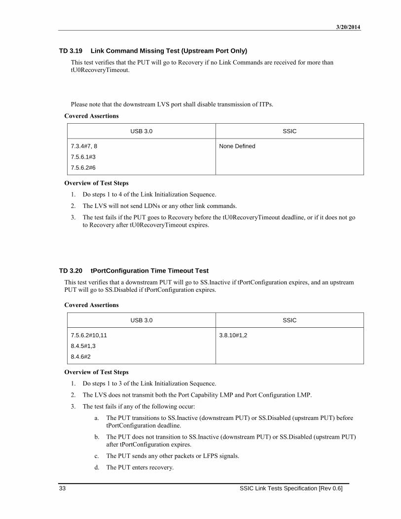
TD 3.19 Link Command Missing Test (Upstream Port Only)
This test verifies that the PUT will go to Recovery if no Link Commands are received for more than
tU0RecoveryTimeout.
Please note that the downstream LVS port shall disable transmission of ITPs.
Covered Assertions
USB 3.0 SSIC
7.3.4#7, 8
7.5.6.1#3
7.5.6.2#6
None Defined
Overview of Test Steps
1. Do steps 1 to 4 of the Link Initialization Sequence.
2. The LVS will not send LDNs or any other link commands.
3. The test fails if the PUT goes to Recovery before the tU0RecoveryTimeout deadline, or if it does not go
to Recovery after tU0RecoveryTimeout expires.
TD 3.20 tPortConfiguration Time Timeout Test
This test verifies that a downstream PUT will go to SS.Inactive if tPortConfiguration expires, and an upstream
PUT will go to SS.Disabled if tPortConfiguration expires.
Covered Assertions
USB 3.0 SSIC
7.5.6.2#10,11
8.4.5#1,3
8.4.6#2
3.8.10#1,2
Overview of Test Steps
1. Do steps 1 to 3 of the Link Initialization Sequence.
2. The LVS does not transmit both the Port Capability LMP and Port Configuration LMP.
3. The test fails if any of the following occur:
a. The PUT transitions to SS.Inactive (downstream PUT) or SS.Disabled (upstream PUT) before
tPortConfiguration deadline.
b. The PUT does not transition to SS.Inactive (downstream PUT) or SS.Disabled (upstream PUT)
after tPortConfiguration expires.
c. The PUT sends any other packets or LFPS signals.
d. The PUT enters recovery.
SSIC Link Tests Specification [Rev 0.6] 34
4. Do steps 1 to 3 of the Link Initialization Sequence.
5. The LVS waits for the Port Capability LMP from the PUT.
6. LVS verifies that the Port Capability LMP is valid.
7. The LVS transmits the Port Capability LMP, but does not transmit the Port Configuration LMP
(downstream LVS port) or Port Configuration Response LMP (upstream LVS port).
8. The test fails if any of the following occur:
a. The PUT does not transmit the Port Capability LMP.
b. The PUT transitions to SS.Inactive (downstream PUT) or SS.Disabled (upstream PUT) before
tPortConfiguration deadline.
c. The PUT does not transition to SS.Inactive (downstream PUT) or SS.Disabled (upstream PUT)
after tPortConfiguration expires.
d. The PUT sends any other packets.
e. The PUT enters recovery.
9. Do steps 1 to 3 of the Link Initialization Sequence
10. The LVS does not transmit the Port Capability LMP, but does send the Port Configuration LMP
(downstream LVS port) or Port Configuration Response LMP if a Port Configuration LMP is received
(upstream LVS port).
11. The test fails if any of the following occur:
a. The PUT does not transmit the Port Capability LMP.
b. The PUT transitions to SS.Inactive (downstream PUT) or SS.Disabled (upstream PUT) before
tPortConfiguration deadline.
c. The PUT does not transition to SS.Inactive (downstream PUT) or SS.Disabled (upstream PUT)
after tPortConfiguration expires.
d. The PUT sends any other packets.
e. The PUT enters recovery.
TD 3.21 Low Power initiation for U1 test (Downstream Port Only)
This test verifies that the PUT initiates U1 state.
Covered Assertions
USB 3.0 SSIC
7.2.4.2.2#1
7.2.4.2.3#1,3,4,5,7,8
7.2.4.2.7#2,3
7.5.7.1#2
7.5.7.2#6
3.8.4.1#1,4
3.8.5#1
3.8.5.2#1,2
7.4#1
Overview of Test Steps
1. Do steps 1 to 4 of the Link Initialization Sequence.
3/20/2014
35 SSIC Link Tests Specification [Rev 0.6]
2. The LVS application prompts the test operator to enable and configure the U1 and U2 inactivity timers
through USB30CV. CV will set the U1 Timeout field to 7Fh and the U2 Timeout field to 00h.
3. The LVS waits to receive an LGO_U1 from the PUT. The LVS transmits an LXU, when it receives the
LGO_U1.
4. The test fails if the PUT sends an LPMA, or if recovery is entered.
5. The LVS waits to receive an LGO_U1 from the PUT again.
6. The LVS transmits an LAU when it receives the LGO_U1.
7. The test fails if any of the following conditions occur:
a. The PUT does not transmit an LPMA before PM_ENTRY_TIMER deadline
b. The PUT enters recovery
c. The PUT does not transition to U1
8. The LVS verifies that both M-RX and M-TX are in STALL state.
9. The LVS initiates HS-BURST on its M-TX and waits to receive HS-BURST on its M-RX.
10. The test fails if the PUT does not enter U0 before Ux_EXIT_TIMER deadline.
11. The test passes if all packets are successful, recovery is entered once, no extra packets are received, and
the PUT returns to U0.
12. After the LVS completes this test case, clear the U1/U2 registers through the CV prompt.
TD 3.22 Low Power initiation for U2 test (Downstream Port Only)
This test verifies that the PUT initiates U2 state.
Covered Assertions
USB 3.0 SSIC
7.2.4.2.2#1,
7.2.4.2.3#1,3,4,5,7,8
7.2.4.2.7#2,3
7.5.8.1#2
7.5.8.2#5
3.8.4.1#6,7,11,12
3.8.6.1#1
3.8.6.2#1
Overview of Test Steps
1. Do steps 1 to 4 of the Link Initialization Sequence.
2. The LVS application prompts the test operator to enable and configure the U1 and U2 inactivity timers
through USB30CV. CV will set the U1 Timeout field to 00h and the U2 Timeout field to 7Fh.
3. The LVS waits to receive an LGO_U2 from the PUT.
4. The LVS transmits an LXU when it receives the LGO_U2.
5. The test fails if the PUT sends an LPMA, or if recovery is entered.
6. The LVS waits to receive an LGO_U2 from the PUT again.
7. The LVS transmits an LAU when it receives the LGO_U2.
8. The test fails if any of the following occur:

SSIC Link Tests Specification [Rev 0.6] 36
a. The PUT does not transmit an LPMA before PM_ENTRY_TIMER deadline.
b. The PUT enters recovery
c. The PUT does transition to U2.
9. The LVS verifies that both the M-TX and M-RX are in the HIBERN8 state and waits for
Rx/Tx_Hibern8Time_Capability + RX_MIN_ActivateTime_Capability (200us).
10. The LVS M-TX initiates a HIBERN8 exit and waits for both M-TX and M-RX to successfully transition
to STALL.
11. The test fails tNoLFPSResponseTimer timeout expires and step 10 has not been completed successfully.
12. The test passes if all packets are successful, recovery is entered once, no extra packets are received, and
the PUT returns to U0.
13. After the LVS completes this test case, clear the U1/U2 registers through the CV prompt.
TD 3.23 PM_LC_TIMER Deadline Test (Downstream Port Only)
This test verifies that the PUT accepts an LGO_U1 sent at the PM_LC_TIMER deadline.
Covered Assertions
USB 3.0 SSIC
7.2.4.2.1#1, 2 None Defined
Overview of Test Steps
1. Do steps 1 to 4 of the Link Initialization Sequence.
2. The LVS application prompts the test operator to enable and configure the U1 and U2 inactivity timers
through USB30CV. CV will set the U1 Timeout field to 7Fh and the U2 Timeout field to 00h.
3. The LVS waits to receive an LGO_U1 from the PUT.
4. The LVS transmits an LAU tLinkTurnAround before the PM_LC_TIMER deadline.
5. The test fails if the PUT does not transmit an LPMA after receiving the LAU.
6. After the LVS completes this test case, clear the U1/U2 registers through the CV prompt.
TD 3.24 PM_LC_TIMER Timeout Test (Downstream Port Only)
This test verifies that the PUT transitions to Recovery when the PM_LC_TIMER expires.
Covered Assertions
USB 3.0 SSIC
7.2.4.2.1#1
7.2.4.2.3#6
7.3.4#6
None Defined
3/20/2014
37 SSIC Link Tests Specification [Rev 0.6]
Overview of Test Steps
1. Do steps 1 to 3 of TD 3.21 .
2. The LVS does not transmit LAU when it receives the LGO_U1.
3. The test fails if the PUT does not transition to Recovery when the PM_LC_TIMER expires.
4. After the LVS completes this test case, clear the U1/U2 registers through the CV prompt.
TD 3.25 PM_ENTRY_TIMER Timeout Test (Upstream Port Only)
This test verifies that the PUT transitions to a low power state when the PM_ENTRY_TIMER expires.
Covered Assertions
USB 3.0 SSIC
7.2.4.2.1#3
7.2.4.2.3#8,10.12
None Defined
Overview of Test Steps
1. Do steps 1 to 4 of TD 3.26 .
2. The LVS does not transmit LPMA when it receives LAU.
3. The test fails if the PUT does not transition to U1 when the PM_ENTRY_TIMER expires, the PUT does
not transmit LAU, or if the PUT sends any packet.
TD 3.26 Accepted Power Management Transaction for U1 Test (Upstream Port Only)
This test verifies that the PUT transitions to U1 if it receives LGO_U1.
Covered Assertions
USB 3.0 SSIC
7.2.4.1.1#7,9
7.2.4.2.1#4
7.2.4.2.2#2,3
7.2.4.2.3#2,8,9
7.2.4.2.7#2,3
7.5.5.1#2
7.5.5.2#2
7.5.7.1#2
7.5.7.2#2
8.4.2#1
3.8.4.1#2,3,5
3.8.5#1
3.8.5.2#1,2
7.4#1
Overview of Test Steps
1. Do steps 1 to 4 of the Link Initialization Sequence.
SSIC Link Tests Specification [Rev 0.6] 38
2. The LVS transmits the Set Link Function LMP with the Force_LinkPM_Accept bit asserted.
3. The LVS transmits an LGO_U1 and waits to receive an LAU from the PUT.
4. The test fails if the PUT does not transmit an LAU before PM_LC_TIMER deadline, or recovery is
entered.
5. The LVS transmits an LPMA and then transition to U1.
6. The test fails if the PUT does not transition to U1 when the PM_ENTRY_TIMER expires, if recovery is
entered, or if the PUT sends any packet.
7. The LVS verifies that both M-RX and M-TX are in STALL state.
8. The LVS initiates HS-BURST on its M-TX and waits to receive HS-BURST on its M-RX.
9. The test fails if the PUT does not enter U0 before Ux_EXIT_TIMER deadline.
10. The test passes if all packets are successful, recovery is entered once, no extra packets are received, and
the PUT returns to U0.
TD 3.27 Accepted Power Management Transaction for U2 Test (Upstream Port Only)
This test verifies that the PUT transitions to U2 if it receives an LGO_U2.
Covered Assertions
USB 3.0 SSIC
7.2.4.1.1#7,9
7.2.4.2.1#4
7.2.4.2.2#2,3
7.2.4.2.3#2,8,9
7.2.4.2.7#2, 3
7.5.8.1#2
7.5.8.2#5
8.4.2#1
3.8.4.1#8,9,10,13
3.8.6.1#1
3.8.6.2#1
Overview of Test Steps
1. Do steps 1 to 4 of the Link Initialization Sequence.
2. The LVS transmits the Set Link Function LMP with the Force_LinkPM_Accept bit asserted.
3. The LVS transmits an LGO_U2 and waits to receive an LAU from the PUT.
4. The test fails if the PUT does not transmit an LAU before PM_LC_TIMER deadline, or if recovery is
entered.
5. The LVS transmits an LPMA and then transitions to U2.
6. The test fails if the PUT does not transition to U2 when the PM_ENTRY_TIMER expires, recovery is
entered, or if the PUT sends any packet.
7. The LVS verifies that both the M-TX and M-RX are in the HIBERN8 state and waits for
Rx/Tx_Hibern8Time_Capability + RX_MIN_ActivateTime_Capability (200us).
8. The LVS M-TX initiates a HIBERN8 exit and waits for both M-TX and M-RX to successfully transition
to STALL.
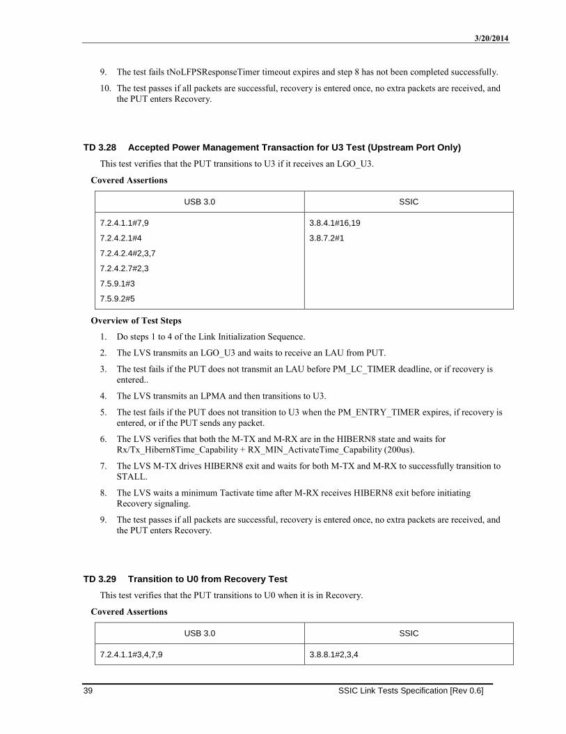
3/20/2014
39 SSIC Link Tests Specification [Rev 0.6]
9. The test fails tNoLFPSResponseTimer timeout expires and step 8 has not been completed successfully.
10. The test passes if all packets are successful, recovery is entered once, no extra packets are received, and
the PUT enters Recovery.
TD 3.28 Accepted Power Management Transaction for U3 Test (Upstream Port Only)
This test verifies that the PUT transitions to U3 if it receives an LGO_U3.
Covered Assertions
USB 3.0 SSIC
7.2.4.1.1#7,9
7.2.4.2.1#4
7.2.4.2.4#2,3,7
7.2.4.2.7#2,3
7.5.9.1#3
7.5.9.2#5
3.8.4.1#16,19
3.8.7.2#1
Overview of Test Steps
1. Do steps 1 to 4 of the Link Initialization Sequence.
2. The LVS transmits an LGO_U3 and waits to receive an LAU from PUT.
3. The test fails if the PUT does not transmit an LAU before PM_LC_TIMER deadline, or if recovery is
entered..
4. The LVS transmits an LPMA and then transitions to U3.
5. The test fails if the PUT does not transition to U3 when the PM_ENTRY_TIMER expires, if recovery is
entered, or if the PUT sends any packet.
6. The LVS verifies that both the M-TX and M-RX are in the HIBERN8 state and waits for
Rx/Tx_Hibern8Time_Capability + RX_MIN_ActivateTime_Capability (200us).
7. The LVS M-TX drives HIBERN8 exit and waits for both M-TX and M-RX to successfully transition to
STALL.
8. The LVS waits a minimum Tactivate time after M-RX receives HIBERN8 exit before initiating
Recovery signaling.
9. The test passes if all packets are successful, recovery is entered once, no extra packets are received, and
the PUT enters Recovery.
TD 3.29 Transition to U0 from Recovery Test
This test verifies that the PUT transitions to U0 when it is in Recovery.
Covered Assertions
USB 3.0 SSIC
7.2.4.1.1#3,4,7,9 3.8.8.1#2,3,4
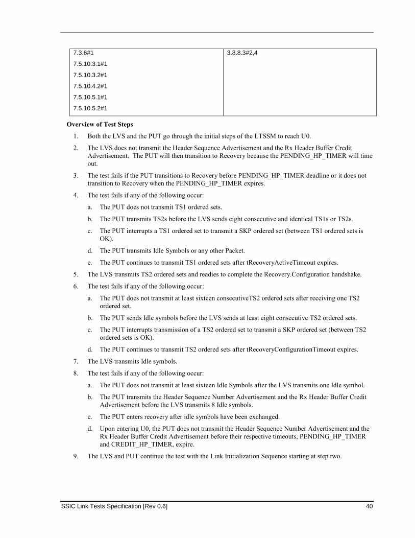
SSIC Link Tests Specification [Rev 0.6] 40
7.3.6#1
7.5.10.3.1#1
7.5.10.3.2#1
7.5.10.4.2#1
7.5.10.5.1#1
7.5.10.5.2#1
3.8.8.3#2,4
Overview of Test Steps
1. Both the LVS and the PUT go through the initial steps of the LTSSM to reach U0.
2. The LVS does not transmit the Header Sequence Advertisement and the Rx Header Buffer Credit
Advertisement. The PUT will then transition to Recovery because the PENDING_HP_TIMER will time
out.
3. The test fails if the PUT transitions to Recovery before PENDING_HP_TIMER deadline or it does not
transition to Recovery when the PENDING_HP_TIMER expires.
4. The test fails if any of the following occur:
a. The PUT does not transmit TS1 ordered sets.
b. The PUT transmits TS2s before the LVS sends eight consecutive and identical TS1s or TS2s.
c. The PUT interrupts a TS1 ordered set to transmit a SKP ordered set (between TS1 ordered sets is
OK).
d. The PUT transmits Idle Symbols or any other Packet.
e. The PUT continues to transmit TS1 ordered sets after tRecoveryActiveTimeout expires.
5. The LVS transmits TS2 ordered sets and readies to complete the Recovery.Configuration handshake.
6. The test fails if any of the following occur:
a. The PUT does not transmit at least sixteen consecutiveTS2 ordered sets after receiving one TS2
ordered set.
b. The PUT sends Idle symbols before the LVS sends at least eight consecutive TS2 ordered sets.
c. The PUT interrupts transmission of a TS2 ordered set to transmit a SKP ordered set (between TS2
ordered sets is OK).
d. The PUT continues to transmit TS2 ordered sets after tRecoveryConfigurationTimeout expires.
7. The LVS transmits Idle symbols.
8. The test fails if any of the following occur:
a. The PUT does not transmit at least sixteen Idle Symbols after the LVS transmits one Idle symbol.
b. The PUT transmits the Header Sequence Number Advertisement and the Rx Header Buffer Credit
Advertisement before the LVS transmits 8 Idle symbols.
c. The PUT enters recovery after idle symbols have been exchanged.
d. Upon entering U0, the PUT does not transmit the Header Sequence Number Advertisement and the
Rx Header Buffer Credit Advertisement before their respective timeouts, PENDING_HP_TIMER
and CREDIT_HP_TIMER, expire.
9. The LVS and PUT continue the test with the Link Initialization Sequence starting at step two.
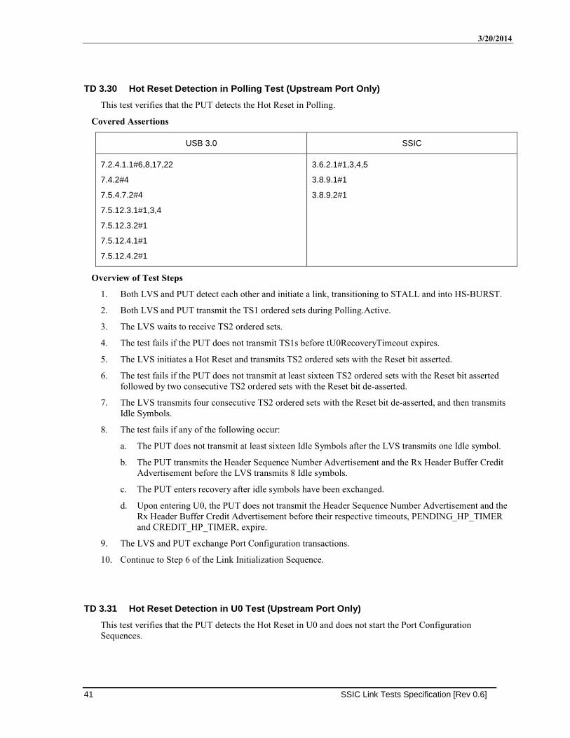
3/20/2014
41 SSIC Link Tests Specification [Rev 0.6]
TD 3.30 Hot Reset Detection in Polling Test (Upstream Port Only)
This test verifies that the PUT detects the Hot Reset in Polling.
Covered Assertions
USB 3.0 SSIC
7.2.4.1.1#6,8,17,22
7.4.2#4
7.5.4.7.2#4
7.5.12.3.1#1,3,4
7.5.12.3.2#1
7.5.12.4.1#1
7.5.12.4.2#1
3.6.2.1#1,3,4,5
3.8.9.1#1
3.8.9.2#1
Overview of Test Steps
1. Both LVS and PUT detect each other and initiate a link, transitioning to STALL and into HS-BURST.
2. Both LVS and PUT transmit the TS1 ordered sets during Polling.Active.
3. The LVS waits to receive TS2 ordered sets.
4. The test fails if the PUT does not transmit TS1s before tU0RecoveryTimeout expires.
5. The LVS initiates a Hot Reset and transmits TS2 ordered sets with the Reset bit asserted.
6. The test fails if the PUT does not transmit at least sixteen TS2 ordered sets with the Reset bit asserted
followed by two consecutive TS2 ordered sets with the Reset bit de-asserted.
7. The LVS transmits four consecutive TS2 ordered sets with the Reset bit de-asserted, and then transmits
Idle Symbols.
8. The test fails if any of the following occur:
a. The PUT does not transmit at least sixteen Idle Symbols after the LVS transmits one Idle symbol.
b. The PUT transmits the Header Sequence Number Advertisement and the Rx Header Buffer Credit
Advertisement before the LVS transmits 8 Idle symbols.
c. The PUT enters recovery after idle symbols have been exchanged.
d. Upon entering U0, the PUT does not transmit the Header Sequence Number Advertisement and the
Rx Header Buffer Credit Advertisement before their respective timeouts, PENDING_HP_TIMER
and CREDIT_HP_TIMER, expire.
9. The LVS and PUT exchange Port Configuration transactions.
10. Continue to Step 6 of the Link Initialization Sequence.
TD 3.31 Hot Reset Detection in U0 Test (Upstream Port Only)
This test verifies that the PUT detects the Hot Reset in U0 and does not start the Port Configuration
Sequences.
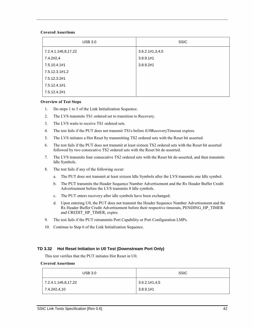
SSIC Link Tests Specification [Rev 0.6] 42
Covered Assertions
USB 3.0 SSIC
7.2.4.1.1#6,8,17,22
7.4.2#2,4
7.5.10.4.1#1
7.5.12.3.1#1,2
7.5.12.3.2#1
7.5.12.4.1#1
7.5.12.4.2#1
3.6.2.1#1,3,4,5
3.8.9.1#1
3.8.9.2#1
Overview of Test Steps
1. Do steps 1 to 5 of the Link Initialization Sequence.
2. The LVS transmits TS1 ordered set to transition to Recovery.
3. The LVS waits to receive TS1 ordered sets.
4. The test fails if the PUT does not transmit TS1s before tU0RecoveryTimeout expires.
5. The LVS initiates a Hot Reset by transmitting TS2 ordered sets with the Reset bit asserted.
6. The test fails if the PUT does not transmit at least sixteen TS2 ordered sets with the Reset bit asserted
followed by two consecutive TS2 ordered sets with the Reset bit de-asserted.
7. The LVS transmits four consecutive TS2 ordered sets with the Reset bit de-asserted, and then transmits
Idle Symbols.
8. The test fails if any of the following occur:
a. The PUT does not transmit at least sixteen Idle Symbols after the LVS transmits one Idle symbol.
b. The PUT transmits the Header Sequence Number Advertisement and the Rx Header Buffer Credit
Advertisement before the LVS transmits 8 Idle symbols.
c. The PUT enters recovery after idle symbols have been exchanged.
d. Upon entering U0, the PUT does not transmit the Header Sequence Number Advertisement and the
Rx Header Buffer Credit Advertisement before their respective timeouts, PENDING_HP_TIMER
and CREDIT_HP_TIMER, expire.
9. The test fails if the PUT retransmits Port Capability or Port Configuration LMPs.
10. Continue to Step 6 of the Link Initialization Sequence.
TD 3.32 Hot Reset Initiation in U0 Test (Downstream Port Only)
This test verifies that the PUT initiates Hot Reset in U0.
Covered Assertions
USB 3.0 SSIC
7.2.4.1.1#6,8,17,22
7.4.2#2,4,10
3.6.2.1#1,4,5
3.8.9.1#1
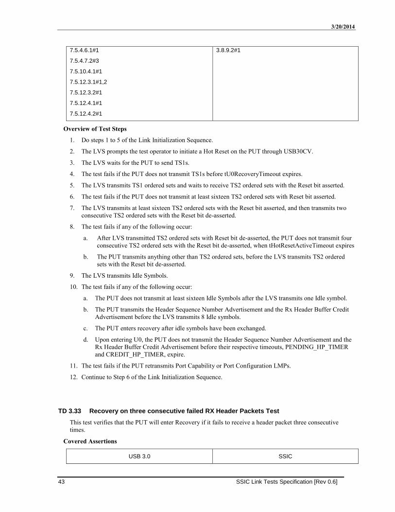
3/20/2014
43 SSIC Link Tests Specification [Rev 0.6]
7.5.4.6.1#1
7.5.4.7.2#3
7.5.10.4.1#1
7.5.12.3.1#1,2
7.5.12.3.2#1
7.5.12.4.1#1
7.5.12.4.2#1
3.8.9.2#1
Overview of Test Steps
1. Do steps 1 to 5 of the Link Initialization Sequence.
2. The LVS prompts the test operator to initiate a Hot Reset on the PUT through USB30CV.
3. The LVS waits for the PUT to send TS1s.
4. The test fails if the PUT does not transmit TS1s before tU0RecoveryTimeout expires.
5. The LVS transmits TS1 ordered sets and waits to receive TS2 ordered sets with the Reset bit asserted.
6. The test fails if the PUT does not transmit at least sixteen TS2 ordered sets with Reset bit asserted.
7. The LVS transmits at least sixteen TS2 ordered sets with the Reset bit asserted, and then transmits two
consecutive TS2 ordered sets with the Reset bit de-asserted.
8. The test fails if any of the following occur:
a. After LVS transmitted TS2 ordered sets with Reset bit de-asserted, the PUT does not transmit four
consecutive TS2 ordered sets with the Reset bit de-asserted, when tHotResetActiveTimeout expires
b. The PUT transmits anything other than TS2 ordered sets, before the LVS transmits TS2 ordered
sets with the Reset bit de-asserted.
9. The LVS transmits Idle Symbols.
10. The test fails if any of the following occur:
a. The PUT does not transmit at least sixteen Idle Symbols after the LVS transmits one Idle symbol.
b. The PUT transmits the Header Sequence Number Advertisement and the Rx Header Buffer Credit
Advertisement before the LVS transmits 8 Idle symbols.
c. The PUT enters recovery after idle symbols have been exchanged.
d. Upon entering U0, the PUT does not transmit the Header Sequence Number Advertisement and the
Rx Header Buffer Credit Advertisement before their respective timeouts, PENDING_HP_TIMER
and CREDIT_HP_TIMER, expire.
11. The test fails if the PUT retransmits Port Capability or Port Configuration LMPs.
12. Continue to Step 6 of the Link Initialization Sequence.
TD 3.33 Recovery on three consecutive failed RX Header Packets Test
This test verifies that the PUT will enter Recovery if it fails to receive a header packet three consecutive
times.
Covered Assertions
USB 3.0 SSIC
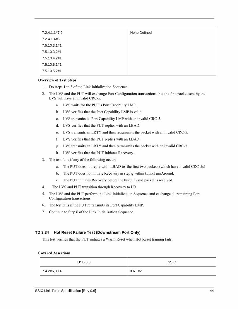
SSIC Link Tests Specification [Rev 0.6] 44
7.2.4.1.1#7,9
7.2.4.1.4#5
7.5.10.3.1#1
7.5.10.3.2#1
7.5.10.4.2#1
7.5.10.5.1#1
7.5.10.5.2#1
None Defined
Overview of Test Steps
1. Do steps 1 to 3 of the Link Initialization Sequence.
2. The LVS and the PUT will exchange Port Configuration transactions, but the first packet sent by the
LVS will have an invalid CRC-5.
a. LVS waits for the PUT’s Port Capability LMP.
b. LVS verifies that the Port Capability LMP is valid.
c. LVS transmits its Port Capability LMP with an invalid CRC-5.
d. LVS verifies that the PUT replies with an LBAD.
e. LVS transmits an LRTY and then retransmits the packet with an invalid CRC-5.
f. LVS verifies that the PUT replies with an LBAD.
g. LVS transmits an LRTY and then retransmits the packet with an invalid CRC-5.
h. LVS verifies that the PUT initiates Recovery.
3. The test fails if any of the following occur:
a. The PUT does not reply with LBAD to the first two packets (which have invalid CRC-5s)
b. The PUT does not initiate Recovery in step g within tLinkTurnAround.
c. The PUT initiates Recovery before the third invalid packet is received.
4. The LVS and PUT transition through Recovery to U0.
5. The LVS and the PUT perform the Link Initialization Sequence and exchange all remaining Port
Configuration transactions.
6. The test fails if the PUT retransmits its Port Capability LMP.
7. Continue to Step 6 of the Link Initialization Sequence.
TD 3.34 Hot Reset Failure Test (Downstream Port Only)
This test verifies that the PUT initiates a Warm Reset when Hot Reset training fails.
Covered Assertions
USB 3.0 SSIC
7.4.2#6,8,14 3.6.1#2
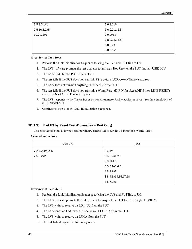
3/20/2014
45 SSIC Link Tests Specification [Rev 0.6]
7.5.3.3.1#1
7.5.10.3.2#5
10.3.1.6#6
3.6.2.1#6
3.6.2.2#1,2,3
3.8.2#1,6
3.8.2.1#3,4,5
3.8.2.2#1
3.8.8.1#1
Overview of Test Steps
1. Perform the Link Initialization Sequence to bring the LVS and PUT link to U0.
2. The LVS software prompts the test operator to initiate a Hot Reset on the PUT through USB30CV.
3. The LVS waits for the PUT to send TS1s.
4. The test fails if the PUT does not transmit TS1s before tU0RecoveryTimeout expires.
5. The LVS does not transmit anything in response to the PUT.
6. The test fails if the PUT does not transmit a Warm Reset (DIF-N for tResetDIFN then LINE-RESET)
after tHotResetActiveTimeout expires.
7. The LVS responds to the Warm Reset by transitioning to Rx.Detect.Reset to wait for the completion of
the LINE-RESET.
8. Continue to Step 1 of the Link Initialization Sequence.
TD 3.35 Exit U3 by Reset Test (Downstream Port Only)
This test verifies that a downstream port instructed to Reset during U3 initiates a Warm Reset.
Covered Assertions
USB 3.0 SSIC
7.2.4.2.4#1,4,5
7.5.9.2#2
3.6.1#2
3.6.2.2#1,2,3
3.8.2#1,6
3.8.2.1#3,4,5
3.8.2.2#1
3.8.4.1#14,15,17,18
3.8.7.2#1
Overview of Test Steps
1. Perform the Link Initialization Sequence to bring the LVS and PUT link to U0.
2. The LVS software prompts the test operator to Suspend the PUT to U3 through USB30CV.
3. The LVS waits to receive an LGO_U3 from the PUT.
4. The LVS sends an LAU when it receives an LGO_U3 from the PUT.
5. The LVS waits to receive an LPMA from the PUT.
6. The test fails if any of the following occur:
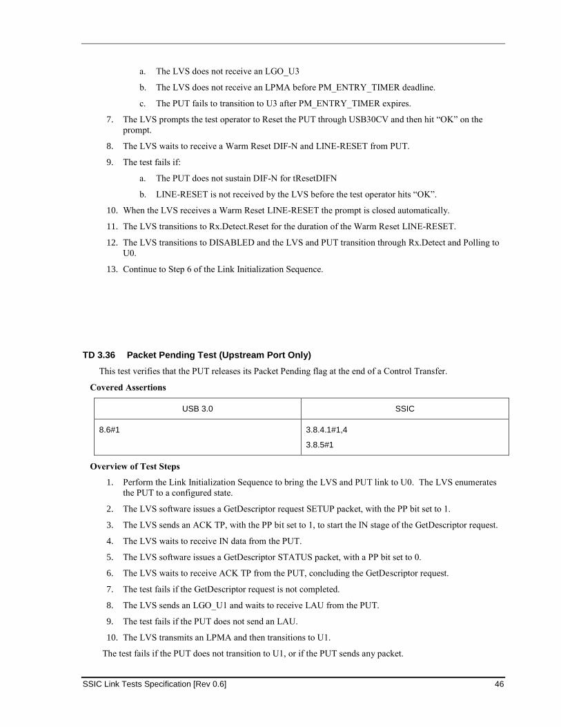
SSIC Link Tests Specification [Rev 0.6] 46
a. The LVS does not receive an LGO_U3
b. The LVS does not receive an LPMA before PM_ENTRY_TIMER deadline.
c. The PUT fails to transition to U3 after PM_ENTRY_TIMER expires.
7. The LVS prompts the test operator to Reset the PUT through USB30CV and then hit “OK” on the
prompt.
8. The LVS waits to receive a Warm Reset DIF-N and LINE-RESET from PUT.
9. The test fails if:
a. The PUT does not sustain DIF-N for tResetDIFN
b. LINE-RESET is not received by the LVS before the test operator hits “OK”.
10. When the LVS receives a Warm Reset LINE-RESET the prompt is closed automatically.
11. The LVS transitions to Rx.Detect.Reset for the duration of the Warm Reset LINE-RESET.
12. The LVS transitions to DISABLED and the LVS and PUT transition through Rx.Detect and Polling to
U0.
13. Continue to Step 6 of the Link Initialization Sequence.
TD 3.36 Packet Pending Test (Upstream Port Only)
This test verifies that the PUT releases its Packet Pending flag at the end of a Control Transfer.
Covered Assertions
USB 3.0 SSIC
8.6#1 3.8.4.1#1,4
3.8.5#1
Overview of Test Steps
1. Perform the Link Initialization Sequence to bring the LVS and PUT link to U0. The LVS enumerates
the PUT to a configured state.
2. The LVS software issues a GetDescriptor request SETUP packet, with the PP bit set to 1.
3. The LVS sends an ACK TP, with the PP bit set to 1, to start the IN stage of the GetDescriptor request.
4. The LVS waits to receive IN data from the PUT.
5. The LVS software issues a GetDescriptor STATUS packet, with a PP bit set to 0.
6. The LVS waits to receive ACK TP from the PUT, concluding the GetDescriptor request.
7. The test fails if the GetDescriptor request is not completed.
8. The LVS sends an LGO_U1 and waits to receive LAU from the PUT.
9. The test fails if the PUT does not send an LAU.
10. The LVS transmits an LPMA and then transitions to U1.
The test fails if the PUT does not transition to U1, or if the PUT sends any packet.
3/20/2014
47 SSIC Link Tests Specification [Rev 0.6]