Embed Size (px)
Citation preview
*Effective *11-14-19
Page 1
For future updates, please refer to the MDT website at http://www.mdt.mt.gov/. Once at the site, click on Doing Business tab, then Contracting and Bidding OR click on http://www.mdt.mt.gov/business/contracting/. The following Subsections have been revised since September 11, 2014. Current revisions are noted by an before the date on this index.
SUPPLEMENTAL SPECIFICATIONS TO MONTANA STANDARD SPECIFICATIONS FOR ROAD AND BRIDGE CONSTRUCTION
2014 EDITION
SUBSECTION TITLE PAGE DATE 101.02 Acronymns and Abbreviations 2 4-25-19 101.03 Definitions (Calendar Day) 6 11-16-17 101.03 Definitions (Completion Date) 6 11-16-17 101.03 Definitions (Contract) 6 *11-14-19 101.03 Definitions (Contract Time) 6 11-16-17 101.03 Definitions (Contractor or Prime Contractor) 7 *11-14-19 101.03 Definitions (Holidays) 8 11-16-17 101.03 Definitions (Major Item) 8 4-25-19 101.03 Definitions (Night or Nighttime) 8 4-25-19 101.03 Definitions (No Work Days) 9 11-16-17 101.03 Definitions (Winter Shutdown) 12 11-16-17 101.03 Definitions (Working Day) 13 11-16-17 102.01 Joint Venture Bids 15 *11-14-19 102.03 Contractor Registration 15 12-11-14 102.07(B) Bidding Requirements 17 9-20-18 102.08 Rejection Of Bid Proposals 18 1-18-18 102.10(B) Internet Bid Submission Via the Internet and Bid ExpressTM 19 9-20-18 102.11 Withdrawal Of Proposals 20 *11-14-19 103.02 Award of Contract 23 *11-14-19 103.09.2 Bid Documentation Inventory Affidavit and Escrow Agreement 24 10-9-14 103.09.5 Release of Bid Documents to the Department 25 8-6-15 103.10 Subcontractor Report 25 7-11-19 104.02.3 Significant Changes in the Character of Work 27 4-25-19 104.05.2 Failure to Properly Maintain Roadway or Structure 29 7-14-16 104.05.4 Maintenance for Traffic During Work Suspensions 30 7-14-16 104.06.1 Rights in and Use of Materials Found on the Project 30 9-20-18 105.02 Contractor Furnished Drawings And Submittals 35 *11*14*19 105.03.3 Quality Incentive Allowance 36 8-6-15 105.03.3(C) Ride Specification (Quality Incentive Allowance) 37 12-11-14 105.05 Cooperation by Contractor 40 9-20-18 105.16.1 Notice of Claim 47 7-14-16 105.16.2 Submission of Certified Claims 48 7-14-16 105.16.3 Decision on Claims 48 1-18-18 105.17.1 Final Walk-through Process 49 2-26-15 105.17.2 Final Acceptance 50 1-18-18 105.17.3 Final Estimate Process 51 4-25-19 106.02.3 Contractor Furnished Sources 55 4-25-19 106.02.5(A) General 56 10-9-14 106.05 Field Laboratory 57 8-6-15 106.09 Domestic Materials 58 *11-14-19 107.11.5 Noxious Weed Management 67 10-9-14 107.11.8 Protection of Aquatic Resources 69 7-14-16 107.13.1 Insurance on All Contracts 69 4-25-19 107.13.2 Insurance Involving Railroads 70 4-25-19 107.18 Contractor’s Responsibility for Utility Property and Services 74 *11-14-19 107.27 Diesel Fuel Used on the Project 75 5-25-17 108.01.1 Subcontracting 77 4-25-19 108.01.2 Contract Performance 77 4-25-19 108.01.3 Subcontractor Payments 78 7-11-19 108.03 Prosecution of Work 78 1-18-18 108.07 Determination of Compensation and Extension of Contract Time for
Excusable, Non-Compensable, and Compensable Delays 83 12-13-18
108.07.1 Completion Date Contracts 83 11-16-17 108.07.2 Calendar Day Contracts 84 11-16-17

*Effective *11-14-19
Page 2
SUPPLEMENTAL SPECIFICATIONS TO MONTANA STANDARD SPECIFICATIONS FOR ROAD AND BRIDGE CONSTRUCTION
2014 EDITION
SUBSECTION TITLE PAGE DATE 108.07.3 Working Day Contracts 84 4-25-19 108.07.5 Extensions 85 8-6-15 108.08 Failure to Complete on Time 86 *11-14-19 109.04.2(A) Labor 92 9-20-18 109.06 Partial Payments 94 4-16-15 109.07 Stockpiled Materials 95 8-6-15 109.10 Overpayments 97 8-6-15 201.03.1 General 99 10-9-14 203.03.1 Excavation 108 10-9-14 203.03.6 Topsoil - Salvaging and Placing 113 1-18-18 204.03.3 Master Blasting and Safety Plan 118 12-8-16 206.03.2(B) Structures 129 12-11-14 208.03.2 Water Pollution Control 133 4-16-15 208.03.3 Aquatic Resource Protection 135 4-16-15 208.05 Basis of Payment 137 4-16-15 208.05.1 Temporary Erosion and Sediment Control - Lump Sum 138 2-26-15 212.01 Description 149 4-16-15 212.03 Construction Requirements 149 4-16-15 212.04 Method of Measurement 149 4-16-15 212.05 Basis of Payment 149 4-16-15 301.02.4 Aggregate Treatment 151 1-18-18 301.02.5 Optional Recycled Material 151 7-11-19 301.03.1 Sampling, Testing, and Acceptance 151 4-25-19 301.03.4 Crushed Aggregate Course 153 5-25-17 301.03.5 Aggregate Surfacing Construction 153 7-14-16 302.02 Materials 159 4-25-19 304.02.4 Blending Material 163 4-25-19 304.02.5 Composition and Proportioning 163 7-11-19 304.03.5 Compaction 165 4-25-19 304.03.1 Cement Treated Pulverized Base 167 7-11-19 304.04.4 Cement Treated Pulverized Base 167 7-11-19 304.05 Basis of Payment 167 7-11-19 401.01 Description 169 5-25-17 401.02 Materials 169 5-25-17 401.02.1 Aggregate 169 7-11-19 401.02.5 Recycled Asphalt Pavement (RAP) 170 7-14-16 401.03 Construction Requirements 170 5-25-17 401.03.1 Mix Design 171 9-20-18 401.03.2 Hamburg Wheel Track Testing (Hamburg) 171 11-16-17 401.03.3 Test Procedures 172 4-25-19 401.03.4(A) Job Mix Formula 172 5-25-17 401.03.5 Acceptance Commercial Plant Mix Surfacing 172 10-9-14 401.03.6 Acceptance of Non-Commercial Plant Mix Surfacing (QA) 173 8-6-15 401.03.17 Tack Coat 178 8-6-15 401.03.18 Surface Conditions, Weather Limitations and Paving Dates 178 11-16-17 401.03.21 Compaction, Compaction Control Testing, and Density Acceptance
Testing 180 4-25-19
401.03.23(A) Ride Specification 181 *11-14-19 401.03.23(B) Surface Smoothness 183 7-14-16 401.03.24 Rumble Strips 184 11-16-17 402.03 Construction Requirements 187 10-9-14 402.03.5 Acceptance 188 7-14-16 402.04 Method of Measurment 192 10-9-14 403.02 Materials 193 8-6-15 403.03.4 Sealing 194 12-11-14 409.02.2 Bituminous Material 197 5-25-17 409.03.1 Sampling, Testing, and Acceptance 197 4-25-19 409.03.3 Seal Coat Limitations 198 2-26-15 409.03.10 Sweeping and Brooming 199 7-14-16 501 Portland Cement Concrete Pavement 209 *11-14-19

*Effective *11-14-19
Page 3
SUPPLEMENTAL SPECIFICATIONS TO MONTANA STANDARD SPECIFICATIONS FOR ROAD AND BRIDGE CONSTRUCTION
2014 EDITION
SUBSECTION TITLE PAGE DATE 551 Hydraulic Cement Concrete 225 *11-14-19 552.02 Materials 251 7-14-16 552.03.3 Forms 251 5-25-17 552.03.10 Removal of Forms and Falsework 255 5-25-17 552.03.18 Silane Sealer 280 *11-14-19 552.03.19 Bridge Deck Crack Sealing 262 1-18-18 553.02.2 Reinforcing Steel 267 7-14-16 553.03.1 Fabrication 268 10-9-14 553.03.11 Transfer of Prestress 274 12-11-14 554.01 Description 279 7-14-16 554.03 Construction Requirements 279 7-14-16 556.03.1 Pre-qualification for Steel Fabricatiors 287 10-9-14 556.03.5 Quality Control 290 1-18-18 556.03.8 Bolted Connections – High-Tensile-Strength Bolts 291 1-18-18 556.03.11 Assembling Steel 315 *11-14-19 558.02.3 Reinforcing Steel 299 7-14-16 558.03.1 Submittals 299 7-14-16 558.03.4 Shaft Excavation 300 7-14-16 558.03.7 Permanent Casing 300 7-14-16 558.03.8 Temporary Casing 301 7-14-16 558.03.10 Cleaning 301 7-14-16 558.03.11 Installation of Cross-hole Sonic Logging (CSL) Tubes 301 7-11-19 558.03.12 Reinforcing Steel 302 7-14-16 558.03.15(A) Cross-hole Sonic Logging 302 7-11-19 558.04.6 CSL Tubes and Testing 303 7-11-19 558.05 Basis of Payment 304 7-14-16 559.03.3 Pile Bearing Resistance 307 4-25-19 559.03.5 Service Pile 310 4-25-19 561.03.3 Procedures 313 10-9-14 561.04 Method of Measurment 314 7-14-16 562.02.1 Reinforcing Steel 315 7-14-16 562.03.3 Location and Inspection of Repair Areas 315 10-9-14 562.03.4 Concrete Removal 315 10-9-14 562.03.5 Reinforcing Steel 316 10-9-14 562.04 Method of Measurement 317 10-9-14 563.02.2 Aggregate 319 4-25-19 563.05 Basis of Payment 322 7-14-16 564.03 Construction Requirements 323 3-10-16 602.04.2 Relay Pipe Culverts 331 7-14-16 603.03.4(A) Backfilling 336 2-26-15 603.03.5 603.04.3
Restoration and Maintenance of Existing Pavement Granular Bedding, Bedding, and Foundation Material
336 337
2-26-15 12-8-16
604.02.3 Reinforcing Steel 339 7-14-16 605 Concrete Barrier Rail 341 *11-14-19 606 Guardrail and Concrete Barrier Rail 341 3-10-16 606.01 Description (Guardrail) 341 3-10-16 606.02 Materials (Guardrail) 341 3-10-16 606.03.1 General (Construction Requirements) 341 3-10-16 606.03.2 Installing Posts 342 12-11-14 606.03.3 Metal Beam Guardrail Erection 342 5-25-17 606.03.7 Concrete Barrier Rail 342 3-10-16 606.04.9 Concrete Barrier Rail 344 3-10-16 606.04.12 Concrete Barrier Rail Transition 344 3-10-16 606.04.13 Concrete Barrier Rail Terminal Section 344 3-10-16 606.04.16 Remove Concrete Barrier Rail 344 3-10-16 606.05 Basis of Payment 345 3-10-16 607.03.3(B) Top Rail or Cable 348 3-10-16 608.02 Materials 353 12-8-16 608.03.3 Detectable Warning Devices 353 4-16-15 608.04 Method of Measurement 353 4-16-15
*Effective *11-14-19
Page 4
SUPPLEMENTAL SPECIFICATIONS TO MONTANA STANDARD SPECIFICATIONS FOR ROAD AND BRIDGE CONSTRUCTION
2014 EDITION
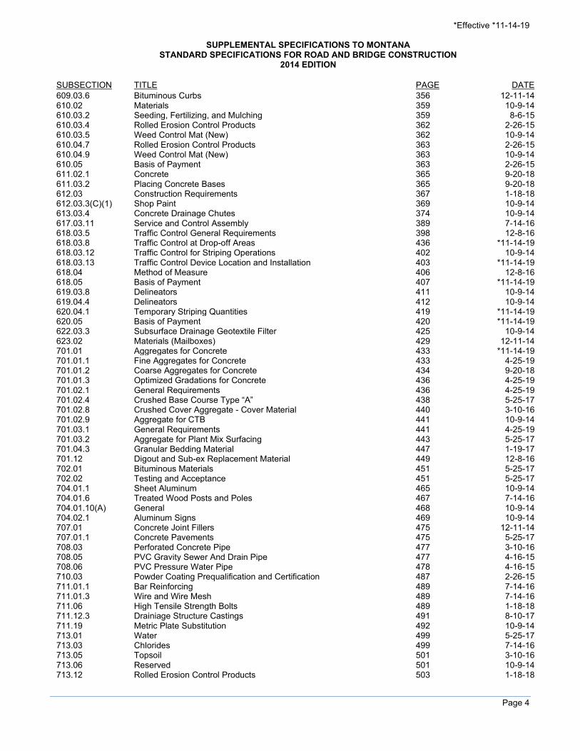
SUBSECTION TITLE PAGE DATE 609.03.6 Bituminous Curbs 356 12-11-14 610.02 Materials 359 10-9-14 610.03.2 Seeding, Fertilizing, and Mulching 359 8-6-15 610.03.4 Rolled Erosion Control Products 362 2-26-15 610.03.5 Weed Control Mat (New) 362 10-9-14 610.04.7 Rolled Erosion Control Products 363 2-26-15 610.04.9 Weed Control Mat (New) 363 10-9-14 610.05 Basis of Payment 363 2-26-15 611.02.1 Concrete 365 9-20-18 611.03.2 Placing Concrete Bases 365 9-20-18 612.03 Construction Requirements 367 1-18-18 612.03.3(C)(1) Shop Paint 369 10-9-14 613.03.4 Concrete Drainage Chutes 374 10-9-14 617.03.11 618.03.5
Service and Control Assembly Traffic Control General Requirements
389 398
7-14-16 12-8-16
618.03.8 Traffic Control at Drop-off Areas 436 *11-14-19 618.03.12 618.03.13 618.04
Traffic Control for Striping Operations Traffic Control Device Location and Installation Method of Measure
402 403 406
10-9-14 *11-14-19
12-8-16 618.05 Basis of Payment 407 *11-14-19 619.03.8 Delineators 411 10-9-14 619.04.4 Delineators 412 10-9-14 620.04.1 Temporary Striping Quantities 419 *11-14-19 620.05 Basis of Payment 420 *11-14-19 622.03.3 Subsurface Drainage Geotextile Filter 425 10-9-14 623.02 Materials (Mailboxes) 429 12-11-14 701.01 Aggregates for Concrete 433 *11-14-19 701.01.1 Fine Aggregates for Concrete 433 4-25-19 701.01.2 Coarse Aggregates for Concrete 434 9-20-18 701.01.3 Optimized Gradations for Concrete 436 4-25-19 701.02.1 General Requirements 436 4-25-19 701.02.4 Crushed Base Course Type “A” 438 5-25-17 701.02.8 Crushed Cover Aggregate - Cover Material 440 3-10-16 701.02.9 Aggregate for CTB 441 10-9-14 701.03.1 General Requirements 441 4-25-19 701.03.2 701.04.3
Aggregate for Plant Mix Surfacing Granular Bedding Material
443 447
5-25-17 1-19-17
701.12 Digout and Sub-ex Replacement Material 449 12-8-16 702.01 Bituminous Materials 451 5-25-17 702.02 Testing and Acceptance 451 5-25-17 704.01.1 Sheet Aluminum 465 10-9-14 704.01.6 Treated Wood Posts and Poles 467 7-14-16 704.01.10(A) General 468 10-9-14 704.02.1 Aluminum Signs 469 10-9-14 707.01 Concrete Joint Fillers 475 12-11-14 707.01.1 Concrete Pavements 475 5-25-17 708.03 Perforated Concrete Pipe 477 3-10-16 708.05 PVC Gravity Sewer And Drain Pipe 477 4-16-15 708.06 PVC Pressure Water Pipe 478 4-16-15 710.03 Powder Coating Prequalification and Certification 487 2-26-15 711.01.1 Bar Reinforcing 489 7-14-16 711.01.3 Wire and Wire Mesh 489 7-14-16 711.06 High Tensile Strength Bolts 489 1-18-18 711.12.3 Drainiage Structure Castings 491 8-10-17 711.19 Metric Plate Substitution 492 10-9-14 713.01 Water 499 5-25-17 713.03 Chlorides 499 7-14-16 713.05 Topsoil 501 3-10-16 713.06 Reserved 501 10-9-14 713.12 Rolled Erosion Control Products 503 1-18-18

*Effective *11-14-19
Page 5
SUPPLEMENTAL SPECIFICATIONS TO MONTANA STANDARD SPECIFICATIONS FOR ROAD AND BRIDGE CONSTRUCTION
2014 EDITION
SUBSECTION TITLE PAGE DATE 713.13 Compost 504 10-9-14 714.03 Temporary Waterborne Traffic Paint 507 7-14-16 714.04 Waterborne Traffic Paint 507 7-14-16 714.05 High Durability Waterborne Traffic Paint 508 7-14-16 714.06 Epoxy or Other Polymeric Traffic Paint 509 7-14-16 714.08 Reflective Glass Beads 512 4-16-15 717.01.3 Liquid Membrane-Forming Concrete Curing Compounds 519 9-20-18 717.01.4 Concrete Cure and Seal Compounds (New) 519 3-10-16 717.01.5 White Polyethylene Sheeting 519 *11-14-19 717.02.2(C) Deck Sealant Sand 519 10-9-14


2014 Supplemental Specifications Page 1
SUPPLEMENTAL SPECIFICATIONS The following are supplementary or amendatory to the 2014 Edition of the Standard Specifications for Road and Bridge Construction insofar as they apply to this contract. 101.02-ACRONYMS AND ABBREVIATIONS Page 2 2-26-15 Rescind and replace the following Acronym:
D/A ...............Dust to actual asphalt ratio Add the following Acronym:
DP ................Dust to effective asphalt ratio Rescind the following Acronym:
CAS ..............Construction Administration Services 101.03 DEFINITIONS (CALENDAR DAY) Page 6 11-16-17 Rescind and replace the following definition: CALENDAR DAY
Every day shown on the calendar, beginning and ending at midnight. 101.03 DEFINITIONS (COMPLETION DATE) Page 6 11-16-17 Rescind and replace the definition COMPLETION DATE the following: FIXED COMPLETION DATE
For Completion Date Contracts, the fixed calendar date that all work on the project is to be complete. 101.03 DEFINITIONS (CONRACT) Page 6 *11-14-19 Rescind the first paragraph and replace the following definition:
The written agreement between the Department and the Contractor detailing the obligations of the parties for the performance of the prescribed work. 101.03 DEFINITIONS (CONTRACTOR OR PRIME CONTRACTOR) Page 7 *11-14-19 Rescind and replace the following definition: CONTRACTOR OR PRIME CONTRACTOR
The individual or legal entity contracting with the Commission to perform the prescribed work. When used in the specifications, Prime Contractor has the same meaning as Contractor. 101.03 DEFINITIONS (HOLIDAYS) Page 8 11-16-17 Rescind and replace the following definition: HOLIDAYS
Legal Holidays as defined in Montana Code Annotated Section 1-1-216. 101.03 DEFINITIONS (MAJOR ITEM) Page 8 4-25-19

2014 Supplemental Specifications Page 2
Rescind and replace the following definition: MAJOR ITEM
Individual bid items having a bid value equal to or exceeding 10% of the total Contractor’s bid. 101.03 DEFINITIONS (NIGHT OR NIGHTTIME) Page 8 4-25-19 Add the following definition: NIGHT OR NIGHTTIME
Defined as the period of time beginning at sunset and ending at sunrise. Night work is that which occurs during this time. The FWP sunrise/sunset tables, available on the FWP website, are used for specific sunrise/sunset times. 101.03 DEFINITIONS (NO WORK DAYS) Page 9 11-16-17 Rescind and replace the following definition:
Days that work is prohibited under the contract. 101.03 DEFINITIONS (WINTER SHUTDOWN) Page 12 11-16-17 Rescind and replace the definition WINTER SHUTDOWN the following: WINTER PERIOD
All days from November 16th through April 15th, inclusive. 101.03 DEFINITIONS (WORKING DAY) Page 13 11-16-17 Rescind and replace the following definition: WORKING DAY
Any day that is charged against contract time in a Working Day contract. 102.03 JOINT VENTURE BIDS Page 15 *11-14-19 Rescind the second sentence of the first paragraph (that begins, “Designate the joint venture..) and replace with the following:
Designate the joint venture business name and specifically authorize a person to execute all bid packages and contracts with the Department on behalf of all individuals and legal entities of the joint venture. 102.03 CONTRACTOR REGISTRATION Page 15 12-11-14 Rescind the first paragraph (that begins, “Montana law…”) and replace with the following:
Montana law requires all contractors, except those exempted by MCA 39-9-211, to register with the Montana Department of Labor & Industry. 102.07(B) BIDDING REQUIREMENTS Page 17 9-20-18 Within the second paragraph, rescind the second sentence (that begins, “Written changes to…”) and replace with the following:
Written changes to the Schedule of Items, or a bidder’s non-submission of every page from the AASHTOWare Project BidsTM EBS file, (including all Schedule of Items pages and all DBE pages), automatically renders the bid non-responsive, and the bid will not be considered.
Within the third paragraph, rescind the third sentence (that begins, “Return a computer…”) and replace with the following:
Return an electronic storage device containing the complete project files for all projects bid with the bid package.
2014 Supplemental Specifications Page 3
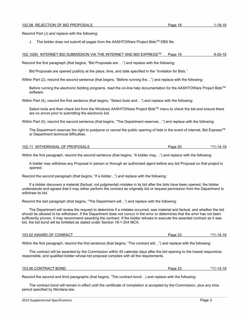
102.08 REJECTION OF BID PROPOSALS Page 18 1-18-18 Rescind Part (J) and replace with the following:
J. The bidder does not submit all pages from the AASHTOWare Project BidsTM EBS file. 102.10(B) INTERNET BID SUBMISSION VIA THE INTERNET AND BID EXPRESSTM Page 19 9-20-18 Rescind the first paragraph (that begins, “Bid Proposals are …”) and replace with the following:
Bid Proposals are opened publicly at the place, time, and date specified in the “Invitation for Bids.” Within Part (2), rescind the second sentence (that begins, “Before running the…”) and replace with the following:
Before running the electronic bidding programs, read the on-line help documentation for the AASHTOWare Project BidsTM software.
Within Part (4), rescind the first sentence (that begins, “Select tools and…”) and replace with the following:
Select tools and then check bid from the Windows AASHTOWare Project BidsTM menu to check the bid and ensure there are no errors prior to submitting the electronic bid.
Within Part (5), rescind the second sentence (that begins, “The Department reserves…”) and replace with the following:
The Department reserves the right to postpone or cancel the public opening of bids in the event of internet, Bid ExpressTM or Department technical difficulties.
102.11 WITHDRAWAL OF PROPOSALS Page 20 *11-14-19 Within the first paragraph, rescind the second sentence (that begins, “A bidder may…”) and replace with the following:
A bidder may withdraw any Proposal in person or through an authorized agent before any bid Proposal on that project is opened.
Rescind the second paragraph (that begins, “If a bidder...”) and replace with the following:
If a bidder discovers a material (factual, not judgmental) mistake in its bid after the bids have been opened, the bidder understands and agrees that it may either perform the contract as originally bid or request permission from the Department to withdraw its bid. Rescind the last paragraph (that begins, “The Department will...”) and replace with the following:
The Department will review the request to determine if a mistake occurred, was material and factual, and whether the bid should be allowed to be withdrawn. If the Department does not concur in the error or determines that the error has not been sufficiently proven, it may recommend awarding the contract. If the bidder refuses to execute the awarded contract as it was bid, the bid bond will be forfeited as stated under Section 18-1-204 MCA. 103.02 AWARD OF CONRACT Page 23 *11-14-19 Within the first paragraph, rescind the first sentence (that begins, “The contract will…”) and replace with the following:
The contract will be awarded by the Commission within 45 calendar days after the bid opening to the lowest responsive, responsible, and qualified bidder whose bid proposal complies with all the requirements. 103.06 CONTRACT BOND Page 23 *11-14-19 Rescind the second and third paragraphs (that begins, “The contract bond…) and replace with the following:
The contract bond will remain in effect until the certificate of completion is accepted by the Commission, plus any time period specified by Montana law.

2014 Supplemental Specifications Page 4
The statutory time for filing claims against the contract bond is 90 calendar days from the date of the Commission acceptance. See Sections 18-2-201 to 18-2-208 MCA. 103.08 FAILURE TO EXECUTE CONTRACT Page 24 *11-14-19 Rescind the last sentence (that begins, “If, due to…) and replace with the following:
If, due to circumstances entirely beyond the control of the bidder, the bidder is unable to file acceptable bonds and insurance policies within the time specified above, the Commission at its sole discretion may waive cancellation of the award and forfeiture of the proposal guaranty. 103.09.2 BID DOCUMENTATION INVENTORY AFFIDAVIT Page 24 10-9-14
AND ESCROW AGREEMENT Within the third (last) paragraph, rescind the web link (that begins, “http://www.…”) and replace with the following:
http://www.mdt.mt.gov/publications/forms.shtml#con 103.09.5 RELEASE OF BID DOCUMENTS TO THE DEPARTMENT Page 25 8-6-15 Rescind the second (last) paragraph (that begins, “Upon the Department’s.…”) and replace with the following:
Within three calendar days of the Escrow Agent’s notification that the Bid Documents will be released to the Department, the Contractor may request to the Department that the Contractor have a representative present during the opening of the bid documents. 103.10 SUBCONTRACTOR REPORT Page 25 7-11-19 Add the following Subsection: 103.10 SUBCONTRACTOR REPORT
No later than 6 calendar days after the date of bid-opening (the date of bid opening to count as the first full day), the apparent low bidder must submit to Construction Contracting Bureau, during its regular work hours, a fully completed Form MDT-CON-102-8 documenting all responding subcontractors, and the work quoted. Include the quoted amount for each subcontractor to be used. If no work is subcontracted, submit Form MDT-CON-102-8 and stipulate “none” within the “subcontractor name” field. If the 6th day is a holiday, turn the documentation in earlier. The DBE commitment information in Expedite must still be reported. The information provided on this form will only be used for reporting at the time of letting.
Form MDT-CON-102-8 is available at the following web page: https://www.mdt.mt.gov/publications/forms/const_forms.shtml.
The bid proposal may be considered non-responsive and rejected if the above form(s) are not submitted within the required time frame. 104.02.3 SIGNIFICANT CHANGES IN THE CHARACTER OF WORK Page 27 4-25-19 Rescind Subsection 104.02.3 and replace with the following: 104.02.3 Significant Changes in the Character of Work
A. Major Item. The Project Manager reserves the right to make, in writing, at any time during the work, such changes in quantities and such alterations in the work as are necessary to satisfactorily complete the project. Such changes in quantities and alterations do not invalidate the contract nor release the surety, and the Contractor agrees to perform the work as altered.
If the alterations or changes in quantities significantly change the character of the work under the contract, whether such alterations or changes are in themselves significant changes to the character of the work or by affecting other work cause such other work to become significantly different in character, an adjustment, excluding anticipated profit, will be made to the contract. The basis for the adjustment must be agreed upon prior to the performance of the work. If a basis cannot be agreed upon, then an adjustment will be made either for or against the Contractor in such amount as the Project Manager may determine to be fair and equitable.
If the alterations or changes in quantities do not significantly change the character of the work to be performed under the contract, the altered work will be paid for as provided elsewhere in the contract.
The term “significant change” applies only to the following circumstances: 1. When the character of the work as altered differs materially in kind or nature from that involved or included in the
original proposed construction; or,
2014 Supplemental Specifications Page 5
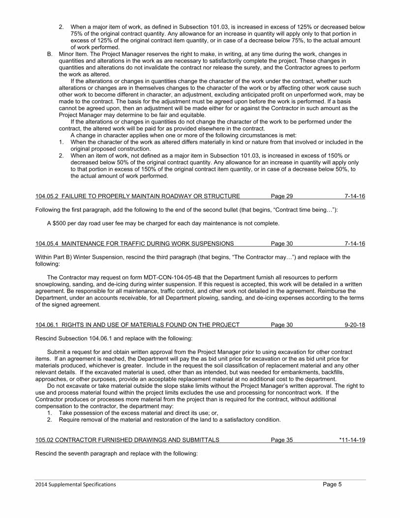
2. When a major item of work, as defined in Subsection 101.03, is increased in excess of 125% or decreased below 75% of the original contract quantity. Any allowance for an increase in quantity will apply only to that portion in excess of 125% of the original contract item quantity, or in case of a decrease below 75%, to the actual amount of work performed.
B. Minor Item. The Project Manager reserves the right to make, in writing, at any time during the work, changes in quantities and alterations in the work as are necessary to satisfactorily complete the project. These changes in quantities and alterations do not invalidate the contract nor release the surety, and the Contractor agrees to perform the work as altered.
If the alterations or changes in quantities change the character of the work under the contract, whether such alterations or changes are in themselves changes to the character of the work or by affecting other work cause such other work to become different in character, an adjustment, excluding anticipated profit on unperformed work, may be made to the contract. The basis for the adjustment must be agreed upon before the work is performed. If a basis cannot be agreed upon, then an adjustment will be made either for or against the Contractor in such amount as the Project Manager may determine to be fair and equitable.
If the alterations or changes in quantities do not change the character of the work to be performed under the contract, the altered work will be paid for as provided elsewhere in the contract.
A change in character applies when one or more of the following circumstances is met: 1. When the character of the work as altered differs materially in kind or nature from that involved or included in the
original proposed construction. 2. When an item of work, not defined as a major item in Subsection 101.03, is increased in excess of 150% or
decreased below 50% of the original contract quantity. Any allowance for an increase in quantity will apply only to that portion in excess of 150% of the original contract item quantity, or in case of a decrease below 50%, to the actual amount of work performed.
104.05.2 FAILURE TO PROPERLY MAINTAIN ROADWAY OR STRUCTURE Page 29 7-14-16 Following the first paragraph, add the following to the end of the second bullet (that begins, “Contract time being…”):
A $500 per day road user fee may be charged for each day maintenance is not complete. 104.05.4 MAINTENANCE FOR TRAFFIC DURING WORK SUSPENSIONS Page 30 7-14-16 Within Part B) Winter Suspension, rescind the third paragraph (that begins, “The Contractor may…”) and replace with the following:
The Contractor may request on form MDT-CON-104-05-4B that the Department furnish all resources to perform snowplowing, sanding, and de-icing during winter suspension. If this request is accepted, this work will be detailed in a written agreement. Be responsible for all maintenance, traffic control, and other work not detailed in the agreement. Reimburse the Department, under an accounts receivable, for all Department plowing, sanding, and de-icing expenses according to the terms of the signed agreement. 104.06.1 RIGHTS IN AND USE OF MATERIALS FOUND ON THE PROJECT Page 30 9-20-18 Rescind Subsection 104.06.1 and replace with the following:
Submit a request for and obtain written approval from the Project Manager prior to using excavation for other contract items. If an agreement is reached, the Department will pay the as bid unit price for excavation or the as bid unit price for materials produced, whichever is greater. Include in the request the soil classification of replacement material and any other relevant details. If the excavated material is used, other than as intended, but was needed for embankments, backfills, approaches, or other purposes, provide an acceptable replacement material at no additional cost to the department.
Do not excavate or take material outside the slope stake limits without the Project Manager’s written approval. The right to use and process material found within the project limits excludes the use and processing for noncontract work. If the Contractor produces or processes more material from the project than is required for the contract, without additional compensation to the contractor, the department may:
1. Take possession of the excess material and direct its use; or, 2. Require removal of the material and restoration of the land to a satisfactory condition.
105.02 CONTRACTOR FURNISHED DRAWINGS AND SUBMITTALS Page 35 *11-14-19 Rescind the seventh paragraph and replace with the following:

2014 Supplemental Specifications Page 6
Working drawings and falsework plans for facilities open to or above public travel ways, including waterways and adjacent banks open for public use, are to be signed by a professional engineer registered in the State of Montana before submittal to the Project Manager. 105.03.3 QUALITY INCENTIVE ALLOWANCE Page 36 8-6-15 Rescind the first paragraph (that begins, “Quality incentive allowances…”) and second paragraphs (that begins, “All quality incentive…”) and replace with the following:
The net incentive or disincentive amount will applied as a line item adjustment on the pay estimate following completion of the item of work. 105.03.3(C) RIDE SPECIFICATION (QUALITY INCENTIVE ALLOWANCE) Page 37 12-11-14 Within Subsection 105.03.3(C), rescind the second paragraph (that begins, “The incentive or disincentive…”) as well as the formulas and variables that follow and replace with the following:
Incentive or disincentive for surface smoothness will be calculated based on the ride category and the entire project length in each travel lane or measured section using the following equation. The calculated value will be applied as a line item adjustment to the plant mix item on the estimate. Calculate the pay adjustment as follows:
Pay adjustment = (Pay Factor -1) x L x Unit Cost Pay Factor = Calculate using appropriate project category formulas L = Measured lane length Unit Cost = Use appropriate value from Table 105-4
Rescind Table 105-4, Unit Cost, and replace with the following:
TABLE 105-4 UNIT COST
Category Description Unit Cost/lft.
I or III Typical section with 0.3 ft. or greater plant mix surfacing $6.425 I, II, or III Typical section with 0.2 to 0.29 ft. plant mix surfacing $4.283 I, II, or III Typical section with 0.19 ft. or less plant mix surfacing $3.213
Note: Isolation lifts are not considered part of the surfacing section when determining appropriate overlay depth. 105.05 COOPERATION BY CONTRACTOR Page 40 9-20-18 Rescind the first paragraph of Subsection 105.05 and replace with the following:
The Department will not furnish hard copies of contract documents. Ensure access to all plans and contract documents is available on the project at all times (whether paper or electronic). Electronic contract documents can be found at the following link, under the appropriate “Bid Packages” links: http://www.mdt.mt.gov/business/contracting/. 105.16.1 NOTICE OF CLAIM Page 47 7-14-16 Within the first paragraph, rescind the first sentence (that begins, “Submit a notice…”) and replace with the following:
Submit a notice of claim using the Department’s Notice of Claim Form MDT-CON-105_16_1A no later than the next business day of disagreements that are to be the subject of a claim for additional compensation, time extension, contract change, or other remedy.
105.16.2 SUBMISSION OF CERTIFIED CLAIMS Page 48 7-14-16 Within the first paragraph, rescind the first sentence (that begins, “If an agreeable…”) and replace with the following:
If an agreeable resolution is not reached within 14 calendar days of the written notice, the Contractor may submit a Certified Claim using the Certified Claim Form MDT-CON-105-16-2 to the Project Manager no more than 7 calendar days after receipt of the Project Manager’s response.

2014 Supplemental Specifications Page 7
105.16.3 DECISION ON CLAIMS Page 48 1-18-18 Rescind the first paragraph (that begins, “The Prime Contractor…”) and replace with the following:
The Prime Contractor must verify the claim data and certify the claim. Claims from a subcontractor or supplier will not be accepted. The DCE will provide a written decision no more than 30 calendar days after receipt of the Certified Claim for contracts that do not require Escrow of Bid Documents. The DCE will provide a written decision no more than 45 calendar days after receipt of Bid Documents for Contracts that require Escrow of Bid Documents. Where a series of claims are filed on contracts that require Escrow of Bid Documents, each claim will have a written decision from the DCE no more than 45 calendar days after the date of receipt of the individual claim. If additional time is required to research and evaluate the Claim, the DCE can extend the time period 14 calendar days by notifying the Contractor in writing.
105.17.1 FINAL WALK-THROUGH PROCESS Page 49 2-26-15 Within part 6, replace the form with the following:
MDT-CON-105_17_1D
Rescind and replace part 7 with the following:
7. The Project Manager will grant Conditional Final Acceptance within 30 calendar days of the receipt of the request for the final walk-through verification. If the punch-list items are fully resolved, no further action is required. If deficiencies still exist, payment will be deducted from the estimate as appropriate. The final acceptance will be granted when all contract-specific warranties have expired and all warranty issues have been resolved.
105.17.2 FINAL ACCEPTANCE Page 50 1-18-18 Within the first paragraph, rescind the first sentence (that begins, “When the Final Walk-through…”) and replace with the following:
When the Final Walk-through Process is complete (conditional final acceptance), all project-specific warranties have expired, and all warranty issues have been resolved, submit the Contractor’s Certificate of Work Complete using form MDT-CON-105_17_2. Rescind bullets 4 (that begins, “There are no pending…) and 5 (that begins, “There are no known…). Add the following bullet (9) following bullet (8)
9. All construction claims made on the contract have been submitted, and are closed or resolved as of this date. 105.17.3 FINAL ESTIMATE PROCESS Page 51 4-25-19 Rescind the second and third paragraphs and replace with the following:
When the final estimate is prepared and all required documentation (such as material certifications, labor dispute resolutions, etc.) has been received, the CES Bureau will send a copy of the final estimate to the Contractor for review. The Contractor has 10 calendar days to notify the Project Manager in writing if the final estimate is acceptable. If no response is received within that timeframe, concurrence will be assumed.
To dispute the final estimate, submit the items disputed and justification to the CES Bureau. Provide a copy to the Project Manager. The CES Bureau will provide a written decision on the disputed items. 106.02.3 CONTRACTOR FURNISHED SOURCES Page 55 4-25-19 Within Part (A), replace MT 214 with AASHTO M 145. Within Part (B), replace MT 209 with AASHTO T 96. 106.02.5(A) GENERAL Page 56 10-9-14 Within the first paragraph, rescind the second sentence (that begins, “Comply with the …”) and replace with the following:

2014 Supplemental Specifications Page 8
Comply with the pertinent statutes relating to open cut mining (Section 82-4 MCA); hard rock mining (Section 82-4-3
MCA); water quality (Section 75-5 MCA); stream bank preservation (Section 75-5 MCA); the Montana County Noxious Weed Management Act Section 7-22-21 MCA; and all other applicable federal, state, and local statutes, regulations and ordinances. 106.05 FIELD LABORATORY Page 57 8-6-15 Rescind Subsection 106.05 and replace with the following: 106.05 FIELD LABORATORY
The Department will furnish all field offices, laboratories and cure boxes. Furnish and install electrical power as directed:
• A continuous 200-ampere, 220 to 230 volt, single phase, 60-hertz power supply using a four wire connector; or • A 110 to 120 volt alternating current of sufficient capacity.
Have the source connected by a Montana licensed electrician. Furnish a potable water supply to operate all testing equipment for the offices and laboratories. Notify the Project Manager at least 2 business days prior to producing material to be tested in the field laboratory or cured
in the cure boxes. Do not begin production until the test trailer or cure box is fully operational. No additional payment will be made for providing power and water to the field offices, laboratories or cure boxes. Include
these costs in the other items on the project. 106.09 DOMESTIC MATERIALS Page 58 *11-14-19 Rescind Subsection 106.09 and replace with the following:
Furnish domestic steel or iron materials for permanent incorporation in the work. Domestic material is material produced by manufacturing processes, including coating of steel or iron, that have occurred entirely in the United States. Pig iron, and processed, pelletized and reduced iron ore may be manufactured outside the United States. In accordance with MT 601, furnish the appropriate manufacturer's documentation of the manufacturing processes, including coatings of covered materials, as performed in the United States. Submit a completed Form 406 for all Category 1 or Category 2 items.
Do not incorporate steel or iron materials into the project until all required documentation is submitted to the Department. Ensure that suppliers understand the contract requirements to supply the required documentation. Domestic steel and iron must meet the requirements of 23 CFR 635.410 and 23 USC Section 313. Submit documentation to the Department in a clear, organized, legible manner or it will be returned. Clarify which material certifications are for which items. The Department will review the submitted documentation one time at no cost to the contractor. If the Department determines that the submitted documentation is inadequate or fails to meet the contract requirements, the submitted documentation will be returned for clarification or correction. The cost for the Department’s re-review of the same submittal is the contractor’s responsibility, and may be deducted from contractor payments.
The Department will not accept items installed until all supporting documentation has been reviewed and is found to be in accordance with the contract requirements. Insufficient or unavailable documentation or documentation showing products to contain steel of foreign origin are grounds for removal and replacement at the contractor’s expense.
Material inspection of pre-cast products, prefabricated steel products, or prefabrication plants will take place at the point of manufacture. The District Materials Lab, Helena Materials Bureau, or Department representative will inspect the manufacturing of these items and verify that the fabricator is maintaining supporting documentation. All precast products containing steel and prefabricated steel products delivered to the project must be accompanied by signed documentation from the end product manufacturer (precast plant or prefabrication plant) which states that all steel used in the product has been melted/recycled and manufactured entirely in the United States and they have maintained supporting documentation. Original mill test reports from steel fabricators or suppliers are not required to be submitted to the Project Manager for precast and prefabricated steel products. Submit a Form 406 with signed documentation by the end product manufacturer or prefabrication plant that all steel incorporated has been melted/recycled and manufactured entirely in the United States. All supporting documentation (original mill test reports) must be maintained by the fabricator and made available to the Department as requested.
A minimal quantity of foreign manufactured steel and iron material may be used if the cost of the material, including delivery costs to the project, does not exceed one-tenth of 1% of the total contract amount or $2,500.00, whichever is greater. Submit a request to use a minimal quantity of foreign manufactured steel and iron a minimum of 5 business days before incorporation into the work. Include in the request the dollar amount of the steel for this request, and the cumulative dollar amount requested to date. Provide documentation, typically in the form of invoices, showing product and delivery cost. Failure to do so will require removal and replacement of all foreign steel and iron with domestic steel and iron. If the foreign steel and iron cannot be positively distinguished from any domestic material used, then all of the material must be removed and replaced with domestic steel and iron at the contractor’s expense.
107.11.5 NOXIOUS WEED MANAGEMENT Page 67 10-9-14
2014 Supplemental Specifications Page 9
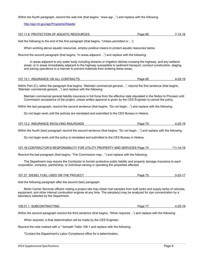
Within the fourth paragraph, rescind the web link (that begins, “www.agr…”) and replace with the following:
http://agr.mt.gov/agr/Programs/Weeds/ 107.11.8 PROTECTION OF AQUATIC RESOURCES Page 69 7-14-16 Add the following to the end of the first paragraph (that begins, “Unless permitted or…”):
When working above aquatic resources, employ positive means to protect aquatic resources below. Rescind the second paragraph (that begins, “In areas adjacent…”) and replace with the following:
In areas adjacent to any water body including streams or irrigation ditches crossing the highway, and any wetland areas; or in areas immediately adjacent to the highway susceptible to sediment transport, conduct construction, staging and paving operations in a manner to prevent materials from entering these areas.
107.13.1 INSURANCE ON ALL CONTRACTS Page 69 4-25-19 Within Part (C), within the paragraph that begins, “Maintain commercial general…”, rescind the first sentence (that begins, “Maintain commercial general…”) and replace with the following:
Maintain commercial general liability insurance in full force from the effective date stipulated in the Notice to Proceed until Commission acceptance of the project, unless written approval is given by the CES Engineer to cancel the policy.
Within the last paragraph, rescind the second sentence (that begins, “Do not begin…”) and replace with the following:
Do not begin work until the policies are reinstated and submitted to the CES Bureau in Helena. 107.13.2 INSURANCE INVOLVING RAILROADS Page 70 4-25-19 Within the fourth (last) paragraph rescind the second sentence (that begins, “Do not begin…”) and replace with the following:
Do not begin work until the policy is reinstated and submitted to the CES Bureau in Helena. 107.18 CONTRACTOR’S RESPONSIBILITY FOR UTILITY PROPERTY AND SERVICES Page 74 *11-14-19 Rescind the last paragraph (that begins, “The Commission may…”) and replace with the following:
The Department may require the Contractor to furnish protective public liability and property damage insurance to each
corporation, company, partnership, or individual owning or operating the properties affected. 107.27 DIESEL FUEL USED ON THE PROJECT Page 75 5-25-17 Add the following paragraph after the second (last) paragraph:
Motor Carrier Services officers visiting a project site may obtain fuel samples from bulk tanks and supply tanks of vehicles, equipment, and other internal combustion engines at any time. The sample(s) may be analyzed for dye concentration by a laboratory selected by the Department. 108.01.1 SUBCONTRACTING Page 77 4-25-19 Within the second paragraph rescind the third sentence (that begins, “When required…”) and replace with the following:
When required, a final determination will be made by the CES Engineer. Rescind the note marked with a * beneath Table 108-1 and replace with the following:
*Contact the Department’s Labor Compliance office for a determination.

2014 Supplemental Specifications Page 10
Add the following sentence to the third paragraph (that begins, “The same criteria…”:
Ensure all subcontracts are submitted through the Prime Contractor. 108.01.2 CONTRACT PERFORMANCE Page 77 4-25-19 Add the following paragraph after the first paragraph:
“Specialty Items” are defined as work that requires highly specialized knowledge, abilities, or equipment not ordinarily available in the type of contracting organizations qualified and expected to bid or propose on the contract as a whole. Within the second paragraph, rescind the second sentence (that begins, “When a portion…”) and replace with the following:
When a portion of an item is subcontracted, the percentage of the work subcontracted will be based on either the subcontract item unit price or on an estimated percentage of the contract item unit price, determined by the CES Engineer. Within the third paragraph, rescind the first sentence (that begins, “Do not allow…”) and replace with the following:
Do not allow a Subcontractor at any contract tier to start work until its subcontract is consented to by the CES Engineer. 108.01.3 SUBCONTRACTOR PAYMENTS Page 78 7-11-19 Rescind Subsection 108.01.3 and replace with the following: 108.01.3 Subcontractor Payments
Submit payment information for all subcontractors and suppliers to the Department within the timeframes shown. Identify any payments that have been withheld from subcontractors or suppliers.
• Prime contractors with first tier subcontractors or suppliers within 7 calendar days of payment from MDT. • First tier subcontractors with second tier subcontractors or suppliers within 7 calendar days of payment from prime
contractor. Submit payment information at the following link: https://app.mdt.mt.gov/spr//.
108.03 PROSECUTION OF WORK Page 78 12-8-16 Rescind Subsection 108.03 and replace with the following: 108.03 PROSECUTION OF WORK 108.03.1 General
Begin obtaining all air quality, water quality and storm water runoff permits, approval of reclamation plans, and archaeological and historical clearances immediately upon receipt of the notice of contract award letter from the Department. Furnish the completed applications to secure permits, approvals or clearances as they are submitted to the respective agency. Furnish approved permits, reclamation plans and clearances necessary to complete the work in conformance with all federal, state and contract requirements.
The Department will reimburse all reasonable costs incurred in securing the permits, approvals and clearances if the Department does not execute the contract for reasons outside its control.
A pre-construction conference will be held on a mutually agreed date between the Contractor, Department and other parties interested in the work before work within the project limits begins no later than 20 calendar days after the Notice to Proceed date. The Contractor’s superintendent in charge of the project must attend the conference. Encourage subcontractors to attend. No payments will be made on the contract until the pre-construction conference has been held.
Obtain written approval before starting night work. Provide work area flood lighting for night work and do not rely solely on equipment lights. Night work approval may be rescinded at any time.
Suspending and resuming work on all or a part of the contract will be by Subsection 105.01. Work may be suspended on working day contracts for unsuitable weather or for other conditions that are detrimental to
the work accuracy and quality. Prevent damage and repair damaged work that was not protected during the suspension at Contractor expense. No time extensions will be approved for work to correct non-protected work.
Store materials to protect against damage and without obstructing, endangering or impeding traffic. Do not allow water to pond on the roadway or within the construction limits, excluding environmental protective devices.
Open ditches and shoulder drains, and take other actions to protect the public and the work. The Department does not authorize project suspension by the Contractor and time will be charged during unauthorized
project suspensions. If the Contractor suspends the project, provide written notification of the suspension to the Project Manager 7 calendar days before the suspension. The Contractor is responsible for all maintenance required during unauthorized suspensions and for all work and materials required due to the suspension.
2014 Supplemental Specifications Page 11
108.03.2 Project Schedules
Furnish a WN that details the work and time (working days, calendar days or completion date) to complete the contract. The initial schedule must show that the work will be completed in the time frame specified in the contract.
A. ASC Schedules. For projects not subject to Subsection 108.03.2(B) requirements, submit a schedule in accordance with the Table of Contractor Submittals. No other work, except obtaining permits, may begin until the schedule requirements have been met. No payments will be made on the contract until the submitted schedule is reviewed.
The Contractor may use a CPM schedule as the ASC if it meets the requirements described in Subsection 108.03.2(A) herein and results in no additional cost to the Department. 1. Include in the ASC:
a. A bar chart chronologically sequenced and to time scale showing the following: 1) All work activities with a completion duration of 5 or more working days. (For this requirement, working days does not exclude the period from November 16th through April 15th.) 2) Any work activity that has an impact on completion of the project.
b. The relationship of each work activity listed in Subsection 108.03.2(A)(1)(a) to other work activities, permits, plans, submittals and approvals required to complete the project.
c. Work activity durations by working days or calendar days as appropriate. Indicate non-working periods exceeding 3 days on each activity bar.
2. Include in the WN: a. The proposed work process sequence describing the relationship of the work activities listed in Subsection
108.03.2(A)(1) required to complete the contract, including shop drawing submittals, permits (including estimated maximum waiting periods for all required permits), fabrication and delivery activities.
b. A detailed description and the progress time of each work activity listed in Subsection 108.03.2(A)(1) measured by working day or calendar day, as appropriate.
c. A detailed description of the ASC, including holidays, planned workdays per week, number of shifts per day, hours per shift, size of work crews and resources used.
d. Adjustments to activity durations and production rates to account for weather. Submit an updated ASC and WN every month in which work is performed, one week before the end of the
project’s monthly estimate cycle. The ASC and WN must show current progress and all revisions or modifications that reflect changes in the method or manner of the work, specification changes, extra work, changes in duration, changes in shifts, work crews or resources.
The Project Manager’s review and acceptance does not attest to the validity of the ASC or WN. B. CPM Scheduling. Develop, maintain and provide a detailed time-scaled computer generated progress schedule using
the critical path method that is compatible with Primavera P6 or other Primavera product which generates a .xer file type.
Submit a schedule in accordance with the Table of Contractor Submittals. No other work, except obtaining permits, may begin until the schedule requirements have been met. No payments will be made on the contract until the submitted schedule is reviewed.
Schedule all contract work including that of subcontractors, vendors and suppliers. The initial schedule must show that the work will be completed in the time frame specified in the contract.
The Project Manager’s review and acceptance of the CPM schedule does not attest to the validity of the Contractor’s assumptions, logic constraints, dependency relationships, resource allocations, labor and equipment or other schedule aspects. 1. Preparation and Submission of Schedule. Prepare an initial schedule and submit an electronic file compatible
with Primavera P6 or other Primavera product which generates a .xer file type. Once an accepted baseline schedule is submitted, furnish one ANSI D (24-inch by 36-inch) paper copy. Submit all items listed in Subsection 108.03.2(B)(3).
Attend a meeting scheduled by the Project Manager within 10 calendar days of the Project Manager’s receipt of the CPM schedule to review, correct or adjust the CPM schedule if required.
Make all schedule adjustments and corrections discussed at the meeting and re-submit the revised schedule within 15 calendar days after the meeting. Plan and execute the work to meet project milestones and completion dates.
2. Initial Schedule Requirements. Include the requirements listed in Subsection 108.03.2(B)(3) and the following: a. Early start sort; b. 60-day look ahead bar charts by early start; and c. Logic diagram having a maximum 100 activities for each ANSI D (24-inch by 36-inch) size sheet. Ensure
each sheet includes project number, page number, title, match data or diagram correlation and key to identify all components used in the diagram.
3. Schedule Requirements. Submit schedules that include: a. Activity identification numbers; b. Project milestones; c. Activity descriptions; d. Appropriate relationships; e. Activity durations of no more than 30 days: f. Procurement of permits;

2014 Supplemental Specifications Page 12
g. Material procurement separated into at least two activities, fabrication and delivery. Include time for delivering all submittals and Department review of working drawing submittals as separate items in the schedule logic for all items requiring submittal, review and approval;
h. Activities coded to reflect the party performing each activity (only one party performs each activity) including subcontractors and suppliers and the area/location of each activity;
j. Phasing (staging) details, if the work has phasing or is to be performed in phases; k. A WN which describes the following:
• Anticipated work in an orderly sequence of the construction phasing; • Work days per week, holidays, number of shifts per day, and hours per shift; • Activity relationships; • Anticipated problems; • Anticipated project completion dates, in a detailed description; and • Activity manpower, equipment, unit quantities and production rates.
WNs that are a listing of the work will not be accepted. Include a WN with each submission; l. Calendars, including no work days as defined in Subsection 101.03, or other Contractor non-work periods.
Use only project specific calendars. All activities must be identified by entry of their appropriate calendar; and
m. Adjustments to activity durations and production rates to account for weather. Use only contractual constraints in the schedule logic. Float is defined as the amount of time between when an activity “can start” and when it “must start”. Total float is
float shared with all other activities and is defined as the amount of time an activity can be delayed without affecting the overall time of project completion. Float is a shared commodity, not for the exclusive use or financial benefit of either party. Either party has the full use of float until it is depleted.
The critical path is defined as the longest continuous sequence of activities through the network schedule that establishes the minimum overall project duration. The submitted activity sequence and durations must generate a CPM schedule having a critical path with zero total float. Keep multiple critical paths and near-critical paths to a minimum. Describe multiple critical paths and near-critical paths with thorough and reasonable justification in the written narrative.
Show the sequence and interdependence of all activities required for the complete performance of all items of work under this contract, including acquiring all the environmental permits. Show all network “dummies” on the diagram.
The Department reserves the right to limit the number of activities on the schedule to between 50 and 1000 activities.
Describe the activities so that the work is identifiable and the progress on each activity is measurable. 4. Schedule Updates. Schedule and attend monthly project progress meetings to compare the schedule to the
actual finish dates of completed activities, the remaining duration of uncompleted activities and the proposed logic and/or time estimate revisions. Provide the status of activities at these meetings, and the schedule updates based on this information, once it has been verified.
Each month of the project, one week before the end of the project’s monthly estimate cycle, submit an electronic file using Primavera P6 or other Primavera product which generates a .xer file type and a .PDF file containing: a. Total float sort; b. The data date and current date line on the bar chart. c. A WN describing the critical path, logic revisions or modifications to the schedule, including, but not limited
to: changes in the method or manner of the work, changes in specifications, extra work, changes in duration, etc.; and
d. Any revised activity on node diagrams for the following: 1) Delay in the completion of any critical activity; 2) Actual prosecution of the work that is different than that represented on the CPM schedule; and 3) The addition, deletion, or revision of activities required by contract modification or logic revisions. Ensure monthly schedule updates reflect the previous month’s actual work. Correct errors listed by the
Project Manager within 3 business days of notification. The contract time will be adjusted only as specified in the contract. Furnish documentation to support requests for time extensions for milestone dates or the contract completion date.
C. Submittal Requirements. Ensure that the WN and project schedules submitted meet the above requirements and accurately reflect the work progress. If the work is not proceeding consistently with the Contractor’s most recently reviewed schedule or WN, the Project Manager may suspend work under Subsection 105.01(A) if the WN or project schedule does not accurately reflect the actual progress of the work; the suspension may continue until an accurate WN and project schedule is submitted.
Any delay in beginning or prosecuting work that is caused by the Contractor’s failure to provide an ASC or WN when, and as required, is the responsibility of the Contractor, and is not an excusable delay.
Prosecute the work with the resources required to complete the contract within the time shown in the Contractor’s updated schedule and WN.
Failure to submit an initial CPM or ASC schedule or schedule update to the Project Manager within 2 calendar days of its due date will result in a monthly deduction in accordance with Table 108.1A.
TABLE 108-1A

2014 Supplemental Specifications Page 13
PROJECT SCHEDULE DEDUCTIONS Original Contract Amount Monthly Deduction From More Than To and Including
$ 0 $ 1,000,000 $ 300 $ 1,000,000 $ 3,000,000 $ 700 $ 3,000,000 ― $ 1,000
C. Method of Measurement
CPM schedule is measured by the lump sum. Other scheduling requirements are not measured for payment. D. Basis of Payment
Payment for all costs associated with CPM scheduling is included in the lump sum contract unit price for CPM scheduling. Payment for all costs associated with other scheduling requirements is included in the payment for other items of work.
The Project Manager may withhold 10% of each monthly progress estimate for failure to submit an initial, updated, or revised WN and CPM or ASC schedule on time and in the manner required. Payment withheld for violation of the schedule requirements will be included in the next progress estimate following the Contractor’s submission of the required schedule.
Partial payments for CPM scheduling will be made based on the lump sum contract unit price as follows: 1. 50% when the initial schedule is finalized. 2. 75% when the overall project is 50% complete. 3. 100% when all updates have been submitted.
108.07 DETERMINATION OF COMPENSATION AND EXTENSION OF CONTRACT Page 83 12-13-18 TIME FOR EXCUSABLE, NON-COMPENSABLE, AND COMPENSABLE DELAYS Rescind Subsection 108.07 and replace with the following: 108.07 CONTRACT TIME AND DETERMINATION OF COMPENSATION AND EXTENSION OF CONTRACT TIME FOR EXCUSABLE, NON-COMPENSABLE, AND COMPENSABLE DELAYS
The contract provisions state the contract completion date or the allowable number of Calendar or Working Days allotted for completion of the contract work.
Do not resume work during an authorized suspension of work without approval from the Project Manager. Do not work on Sundays and Holidays without written approval from the Engineer. Travelway maintenance in accordance
with Subsection 104.05.2, stormwater BMP maintenance, and providing protection for the public are exempt work items and may be performed on No-Work Days without assessment of contract time. 108.07.1 COMPLETION DATE CONTRACTS Page 83 11-16-17 Rescind Subsection 108.07.1 and replace with the following:
Begin work on the effective date stated in the Notice to Proceed. Complete all work by the completion date specified in the contract.
The completion date will be extended for the following: A. Extensions of contract time added in accordance with Subsection 108.07.5; or B. Suspensions of work authorized after the contract is awarded (other than the winter period); or C. Delays in the award of the contract. The new completion date is determined by adding the Calendar Days granted under Subsection 108.07.5; the number of
Calendar Days during authorized suspensions (other than the winter period); or the number of Calendar Days the Award was delayed past the posted award date to the specified completion date, with equitable time adjustment for No-Work Days.
The actual completion date is the date the Project Manager approves the Contractor’s Certificate of Work Complete form in accordance with Subsection 105.17.2.
Contract time overruns for assessment of liquidated damages will be computed as the number of Calendar Days elapsing between the contract Completion Date and the actual completion date. 108.07.2 CALENDAR DAY CONTRACTS Page 84 11-16-17 Rescind Subsection 108.07.2 and replace with the following:
Begin work on the effective date stated in the Notice to Proceed. Complete all work within the number of Calendar Days specified in the contract.
Except during authorized suspensions, every day on the calendar is assessed against contract time, including No Work Days.

2014 Supplemental Specifications Page 14
Contract time assessment will cease when the Project Manager approves the Contractor’s Certificate of Work Complete form under Subsection 105.17.2.
Contract time overruns for assessment of liquidated damages will be computed as the number of Calendar Days the contract is not complete beyond the contract time specified. 108.07.3 WORKING DAY CONTRACTS Page 84 4-25-19 Rescind Subsection 108.07.3 and replace with the following:
Begin work on the effective date stated in the Notice to Proceed. Complete all work within the number of Working Days specified in the contract provisions.
Meet the requirements in Table 108-3: TABLE 108-3
HOLIDAY CONTRACT TIME ASSESSMENT Holiday: Stop Work by: Return to Work: Memorial Day 3:00pm on the Preceding Friday1 Tuesday Labor Day 3:00pm on the Preceding Friday1 Tuesday When July 4 Occurs On: Stop Work by: Return to Work2: Monday 3:00pm on the Preceding Friday1 Tuesday Tuesday The end of day on the Preceding Friday Wednesday Wednesday 3:00pm on the Preceding Tuesday1 Thursday Thursday 3:00pm on the Preceding Wednesday1 Monday Friday 3:00pm on the Preceding Thursday1 Monday Saturday 3:00pm on the Preceding Thursday1 Monday Sunday 3:00pm on the Preceding Friday1 Tuesday
Note 1: If all work operations are stopped before 12:00pm (noon), contract time will not be assessed on this day. Note 2: Contract time will not be assessed between the stop work by and return to work days.
Contract time assessment will cease when the Project Manager approves the Contractor’s Certificate of Work Complete
form in accordance with Subsection 105.17.2. All days except No-Work days are assessed against the contract time, except as follows: contract time will not be
assessed on: • Winter Period days that the Contractor does not work; • Winter Period days when the work has no impact to the traveling public; or, • On any Saturdays that the Contractor does not work. Traffic flowing unimpeded on approved detours is considered to have no impact on the traveling public. Contract time will
not be assessed for days having inclement weather or the aftermath of inclement weather that prevent the Contractor from working at least six hours in the day. Inclement weather will not be considered when assessing time if the contractor is not actively performing work or is not scheduled to work. Suspension of work is authorized for the Winter Period.
Chargeable and non-chargeable working days will be determined daily by the Project Manager. For any week that the Contractor has chargeable days, the Project Manager will furnish a weekly report on the following Monday showing the number of working days:
A. Charged for the preceding week; B. Previously charged; C. Specified for contract completion; D. Approved time extensions; and E. Remaining to complete the contract. Submit a written protest to the Project Manager within the timeframe shown on the weekly report for any alleged
discrepancies in the time assessed. Failure to file a protest is conclusive evidence that the time assessed is accepted as correct.
Contract time overruns for assessment of liquidated damages will be computed as the number of working days assessed beyond the contract time specified. 108.07.5 EXTENSIONS Page 85 8-6-15 Rescind the third paragraph (that begins, “The contract time…”) and replace with the following:
The contract time as awarded is based on the estimated quantities as defined in Subsection 102.05. No decrease in contract time will be made for an underrun in a contract item quantity. The contract time will be modified based on the quantity and difficulty of added or deleted work and how it impacts the critical activities of the Contractor’s operation as shown on the most current work schedule as required under Subsection 108.03 or as justified to the Project Manager.

2014 Supplemental Specifications Page 15
108.08 FAILURE TO COMPLETE ON TIME Page 86 4-25-19 Rescind Table 108-2 and replace with the following:
TABLE 108-1 SCHEDULE OF LIQUIDATED DAMAGES
ORIGINAL CONTRACT AMOUNT DAILY CHARGE From More Than To and Including Working Day or Calendar Day
$ 0 $ 100,000 $ 1,116 $ 100,000 $ 300,000 $ 1,430 $ 300,000 $ 700,000 $ 1,629 $ 700,000 $ 1,500,000 $ 1,898 $ 1,500,000 $ 3,000,000 $ 2,066 $ 3,000,000 $ 5,000,000 $ 2,501 $ 5,000,000 $ 10,000,000 $ 3,053 $ 10,000,000 — $ 3,850
Rescind the third paragraph (that begins, “If the Contractor …”) and replace with the following:
If the Contractor disputes the liquidated damages on the approved “Contractor’s Certificate of Work Complete” form, the CES Bureau will send a final notification in writing to the Contractor of the number of days to be assessed and the dollar amount of proposed liquidated damages. Submit any objections of the assessment to the CES Bureau in writing within 30 calendar days of receipt of the Department’s notification. Include with the objection the justification and all information to support an adjustment to the assessment. The Department will review the Contractor’s information and perform a final analysis.
Within the fourth paragraph, rescind the second sentence (that begins, “The CAS Bureau …”) and replace with the following:
The CES Bureau will submit the Contractor’s information and the Department’s recommendation to the Commission. Rescind the last paragraph (that begins, “The Commission will review …”) 109.04.2(A) LABOR Page 92 9-20-18 Rescind Part A. Labor and replace with the following:
A. Labor. The Contractor is paid the wage rates for all labor and foremen assigned exclusively to performing the extra work for the total hours worked on-site plus 80% of the total. The 80% surcharge may be increased if supporting documentation is submitted by a certified public accountant (CPA) showing that a higher percentage surcharge is needed to cover labor costs. This documentation may be audited to determine compliance of allowable surcharges. The wage rates used for the above computation will not include travel pay (unless included in the USDOL wage decision) or fringe benefits, whether or not paid directly to the employees. Payment as described above is full compensation for all labor related expenses incurred including but not limited to premiums for worker’s compensation insurance, public liability and property damage insurance, social security, unemployment compensation, health and welfare expenses, and other expenses imposed by federal or state laws or both. Submit evidence of the actual wage rates paid. Only labor on certified payrolls is eligible. The rate paid will be that which is listed on the certified payroll. 109.06 PARTIAL PAYMENTS Page 94 4-16-15 Rescind the second paragraph (that begins, “The Department reserves…”) and replace with the following:
The Department reserves the right to withhold all or part of any partial payments earned under the contract until all tax payments due or owed to the State of Montana are paid in full. 109.07 STOCKPILED MATERIALS Page 95 8-6-15 Add the following sentence at the end of the seventh paragraph (that begins, “Partial Payments…):
Submit stockpiled materials requests using the same unit of measure as the contract item.

2014 Supplemental Specifications Page 16
109.10 OVERPAYMENTS Page 97 8-6-15 Within part 1 rescind the forth sentence (that begins, “The interest rate…”) and replace with the following:
The interest rate charged will be the greater of 10% or the highest rate allowed by the law for the period in which the overpayment is not repaid. 201.03.1 GENERAL Page 99 10-9-14 Rescind the seventh paragraph (that begins, “Stake construction limits …”) and replace with the following:
Stake construction limits for cuts, fills, channel changes, ditches, fence lines, utility relocation, roadside development areas, selective thinning for sight distance, grubbing, and similar areas to establish clearing and grubbing limits in accordance with Subsection 105.08. 203.03.1 EXCAVATION Page 108 10-9-14 Rescind the second paragraph of Subsection (G) Digout, (that begins, “Provide special…”) and replace with the following:
Furnish replacement material for digouts in accordance with Subsection 701.12. Rescind the first and second paragraphs of Subsection (H) Sub Excavation, (that begins, “In areas of…”) and replace with the following:
Unless otherwise shown in the contract or directed by the Project Manager, in areas of sub excavation, excavate the full road width to a depth of 2 feet (600 mm) below the top of the subgrade soils or to a depth where the subgrade soils are firm and stable, whichever is shallower. Excavate parallel to the finish grade, day lighting to the left and right slopes. Slope the ends of the excavation no steeper than a 10H:1V. Dispose of the excavated material to the satisfaction of the Project Manager.
Furnish sub-ex replacement material in accordance with Subsection 701.12. 203.03.6 TOPSOIL - SALVAGING AND PLACING Page 113 1-18-18 Add the following to the end of the fifth paragraph:
Limit individual stockpile lengths to 500 feet (150 m) maximum. Place a break between stockpiles of at least 40 feet (12 m). 204.03.3 MASTER BLASTING AND SAFETY PLAN Page 118 12-8-16 Rescind the first sentence and replace with the following: Submit a Master Blasting and Safety Plan on form MDT-CON-204-03-03, along with any comments from the Blasting Consultant, to the Project Manager for review at least 10 business days before the start of test or production drilling operations or at any time the drilling and blasting methods, or explosive type or product are changed. Within Part A. Blasting Plan, replace the first sentence with: Blasting Plan. Include the following information, at a minimum, in the blasting portion of the plan: Within Part B. Safety Plan, rescind and replace the first paragraph with: Safety Plan. Include the following information, at a minimum, in the Safety portion of the plan: 206.03.2(B) STRUCTURES Page 129 12-11-14 Rescind Subsection 206.03.2(B) and replace with the following:
B. Structures. If a bridge is chosen as means for conveyance of the waterway, provide a minimum waterway opening of sufficient size to accommodate the 2-year flood event, spanning the active channels with 1-foot (305 mm) minimum freeboard. Construct all temporary bents in a manner that the current remains un-deflected. Provide adequate bulkheads at the approach fills to prevent fill materials from entering the waterway.
2014 Supplemental Specifications Page 17
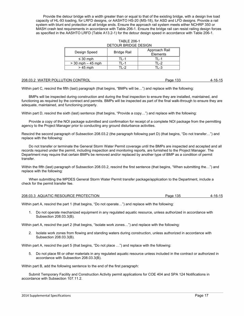
Provide the detour bridge with a width greater than or equal to that of the existing bridge, with a design live load capacity of HL-93 loading, for LRFD designs, or AASHTO HS-20 (MS-18), for ASD and LFD designs. Provide a rail system with blunt end protection at all bridge ends. Ensure the approach rail system meets either NCHRP 350 or MASH crash test requirements in accordance with Table 206-1. Ensure the bridge rail can resist railing design forces as specified in the AASHTO LRFD (Table A13.2-1) for the detour design speed in accordance with Table 206-1.
TABLE 206-1 DETOUR BRIDGE DESIGN
Design Speed Bridge Rail Approach Rail Elements
≤ 30 mph TL-1 TL-1 > 30 mph – 45 mph TL-1 TL-2
> 45 mph TL-2 TL-3 208.03.2 WATER POLLUTION CONTROL Page 133 4-16-15 Within part C, rescind the fifth (last) paragraph (that begins, “BMPs will be…”) and replace with the following:
BMPs will be inspected during construction and during the final inspection to ensure they are installed, maintained, and functioning as required by the contract and permits. BMPs will be inspected as part of the final walk-through to ensure they are adequate, maintained, and functioning properly. Within part D, rescind the sixth (last) sentence (that begins, “Provide a copy…”) and replace with the following:
Provide a copy of the NOI package submitted and confirmation for receipt of a complete NOI package from the permitting agency to the Project Manager prior to conducting any ground disturbance activities. Rescind the second paragraph of Subsection 208.03.2 (the paragraph following part D) (that begins, “Do not transfer…”) and replace with the following:
Do not transfer or terminate the General Storm Water Permit coverage until the BMPs are inspected and accepted and all records required under the permit, including inspection and monitoring reports, are furnished to the Project Manager. The Department may require that certain BMPs be removed and/or replaced by another type of BMP as a condition of permit transfer. Within the fifth (last) paragraph of Subsection 208.03.2, rescind the first sentence (that begins, “When submitting the…”) and replace with the following:
When submitting the MPDES General Storm Water Permit transfer package/application to the Department, include a check for the permit transfer fee. 208.03.3 AQUATIC RESOURCE PROTECTION Page 135 4-16-15 Within part A, rescind the part 1 (that begins, “Do not operate…”) and replace with the following:
1. Do not operate mechanized equipment in any regulated aquatic resource, unless authorized in accordance with Subsection 208.03.3(B).
Within part A, rescind the part 2 (that begins, “Isolate work zones…”) and replace with the following:
2. Isolate work zones from flowing and standing waters during construction, unless authorized in accordance with Subsection 208.03.3(B).
Within part A, rescind the part 5 (that begins, “Do not place …”) and replace with the following:
5. Do not place fill or other materials in any regulated aquatic resource unless included in the contract or authorized in accordance with Subsection 208.03.3(B).
Within part B, add the following sentence to the end of the first paragraph:
Submit Temporary Facility and Construction Activity permit applications for COE 404 and SPA 124 Notifications in accordance with Subsection 107.11.2.

2014 Supplemental Specifications Page 18
Rescind the fifth (last) paragraph of Subsection 208.03.3 (that begins, “Submit copies of…”) and replace with the following:
Submit copies of the plans and application packages, their modifications, or their revisions to the Project Manager. The Department will review each submittal of the plans and application packages, their modifications, or their revisions, and either request revisions or submit to applicable resource and regulatory agencies within 21 calendar days. Resource and regulatory agency review time does not begin until the Department submits the application to the applicable agencies. Do not begin work on temporary construction facilities or modifications to approved plans until receiving written notification from the Project Manager that all of the required approvals from the regulatory and resource agencies have been obtained and distributed. The Department will distribute COE 404 and SPA 124 approvals within 5 business days of receipt of all required approvals. 208.05 BASIS OF PAYMENT Page 137 4-16-15 Within the second paragraph, rescind the first sentence (that begins, “Failure to implement…”) and replace with the following:
Failure to provide erosion and sediment controls that prevent discharges to adjacent properties and/or aquatic resources, implement BMPs identified in the SWPPP, update the SWPPP as required by the Construction General Permit, or conduct BMP inspections and submit inspection reports renders the BMPs unacceptable. 208.05.1 TEMPORARY EROSION AND SEDIMENT CONTROL - LUMP SUM Page 138 2-26-15 Within Table 208-1, rescind the term “substantial work complete date” and replace with “Conditional final acceptance”. Within the third paragraph, rescind the third sentence (that begins “Payment for quantities..”) and replace with the following:
Payment for quantities required by an event or extra work, and approved by the Project Manager, will be measured and paid for in accordance with the Erosion Control Rate Schedule contained in the contract at a unit price of $1.00 per unit.
Rescind the fourth paragraph (that begins, “The installation of additional…”) and replace with the following”
The installation of additional BMPs requested by the Department at the final inspection will be measured and paid for in
accordance with the Erosion Control Rate Schedule. 212.01 DESCRIPTION Page 149 4-16-15 Rescind the first (only) paragraph (that begins, “Obliterate roadway…”) and replace with the following:
Obliterate roadway includes removal of the existing roadway and related items, rehabilitating the abandoned roadway area by scarifying and shaping, and re-vegetation. 212.03 CONSTRUCTION REQUIREMENTS Page 149 4-16-15 Within the third paragraph, rescind the third (last) sentence (that begins, “Spread the salvaged…”) and replace with the following:
Re-vegetate the disturbed areas in accordance with Section 610.. 212.04 METHOD OF MEASURMENT Page 149 4-16-15 Rescind the second and third paragraphs and replace with the following:
Re-vegetation is measured and paid for in accordance with Section 610. 212.05 BASIS OF PAYMENT Page 149 4-16-15 Remove the following pay items and units from the table:
Pay Item Pay Unit Seeding Acre (ha) Topsoil Cubic Yard (m3)

2014 Supplemental Specifications Page 19
301.02.4 AGGREGATE TREATMENT Page 151 1-18-18 Rescind the first paragraph (that begins, “Choose the material…) and replace with the following:
Choose the material that will be used to treat the aggregate, which may include MC-70, or calcium or magnesium chloride. 301.02.5 OPTIONAL RECYCLED MATERIAL Page 151 7-11-19 Add the following subsection: 301.02.5 Optional Recycled Material
RAP or Recycled Concrete Aggregate (RCA) may be blended with existing crushed aggregate course, additional aggregate course, or a combination of these. Ensure blended material meets the requirements of Subsections 701.02.1 and 701.02.4.
1. Pugmill recycled products with existing or virgin aggregates to produce a uniform mixture. 2. Blend no more than 40% RAP or 50% RCA by weight with existing or virgin aggregates. 3. Total recycled mixtures may not exceed 50% by weight of the blended base course. 4. Use weighing or metering devices to control the recycled material introduced into the mix within the specified limits.
301.03.1 SAMPLING, TESTING, AND ACCEPTANCE Page 151 4-25-19 Within Part(B), replace MT 217 with AASHTO T 335. 301.03.4 CRUSHED AGGREGATE COURSE Page 153 5-25-17 Within the third paragraph, rescind the first sentence (that begins, “Indicate the selected…”) and replace with the following:
Indicate the selected option and the grade of crushed base course (Type “A” grade 5, Type “A” grade 6, or Type “A” grade 7) before beginning aggregate production. 301.03.5 AGGREGATE SURFACING CONSTRUCTION Page 153 7-14-16 Within Part A, add the following Number 4:
4. Unstable or pumping material is unacceptable. Rework or remove and replace the material prior to placing additional lifts or materials.
Within Part H, Table 301-1 Surface Smoothness, replace the aggregate size (that specifies, “1-inch (25 mm) and less”) with the following:
Less than 1½-inch (40 mm) 302.02 MATERIALS Page 159 4-25-19 Add the following to the list of acceptable crushed aggregate courses:
Crushed Aggregate Course Type “A” Grade 7 701.02.4 304.02.4 BLENDING MATERIAL Page 163 4-25-19 Replace MT 208 with AASHTO T 89 and AASHTO T 90. 304.02.5 COMPOSITION AND PROPORTIONING Page 163 7-11-19 Within the first paragraph, rescind the first sentence (that begins, “Develop and submit…”) and replace with the following:
Develop and submit a proposed CTB or Cement Treated Pulverized Base mix design for approval.

2014 Supplemental Specifications Page 20
Within Part 2, replace MT 211 with AASHTO T 134. Within Part 7, replace MT 208 with AASHTO T 89 and AASHTO T 90. Rescind Part 8 and replace with the following:
8. Sand equivalent determined in accordance with AASHTO T 176 alternate method No. 2 using stock solution with formaldehyde.
304.03.5 COMPACTION Page 165 4-25-19 Replace MT 211 with AASHTO T 134. 304.03.14 CEMENT TREATED PULVERIZED BASE Page 167 7-11-19 Add the following subsection: 304.03.14 Cement Treated Pulverized Base
When required by the Contract, process the existing plant mix surfacing with the existing base course and/or add crushed aggregate course and cementitious material as needed to restore the roadway section to the grade and dimensions shown in the Contract.
A. Requirements. Use equipment capable of pulverizing and mixing road sections to the depths shown in the plans. The equipment must be able to utilize a water spray or injection system capable of uniformly mixing the water, pulverized material and cementitious material together. Meet the construction requirements of Section 304 with the following exceptions: 1. Begin production at the mix design targets for cementitious material and moisture content. Adjust cementitious
material and moisture content as directed by the Project Manager to get compressive strengths between 500 and 1500 psi (35 and 104 KPa) as tested in accordance with MT 216. Changes in the amount of cementitious material used must be approved by the Project Manager.
2. Immediately suspend operations due to detrimental weather conditions (e.g. wind and/or rain). 3. Spread cementitious material uniformly on top of the pulverized surface. The spreading operation cannot exceed
1000 feet (300 m) ahead of the pulverizing operation. 4. Perform mixing of cementitious material and pulverized base with pulverizing equipment. 5. Shape the compacted surface to the specified lines, grades, and cross sections meeting the requirements of
Subsection 105.08. 6. Do not perform any subsequent work on the completed roadway sections until accepted by the Project Manager.
Water must be introduced at the mixing stage. Water added after mixing and prior to compaction will not be allowed. Complete compaction within 2 hours after re-mixing is complete.
B. Sequencing. 1. Pulverize the road to the specified depth and width as shown in the plans. 2. Uniformly place cementitious material across the width of the roadway section on top of the pulverized base. 3. Re-mix the pulverized sections and cementitious material with the pulverizing equipment. 4. Compact the re-mixed and completed sections. 5. Shape completed sections to the specified grade. 6. Apply the curing seal and blotter.
304.04.4 CEMENT TREATED PULVERIZED BASE Page 167 7-11-19 Add the following subsection: 304.04.4 Cement Treated Pulverized Base
Cement Treated Pulverized Base is measured by the square yard (square meter) based on the designated width shown in the plans.
Crushed Aggregate Course is measured by the cubic yard (cubic meter) as a predetermined pay quantity as described elsewhere in this contract.
Portland cement is measured by the ton (metric ton) in accordance with Subsection 109.01. Fly ash, if included, is measured by the ton (metric ton) and the quantity added to the measured quantity of portland cement. 304.05 BASIS OF PAYMENT Page 167 7-11-19 Rescind Subsection 304.05 and replace with the following:
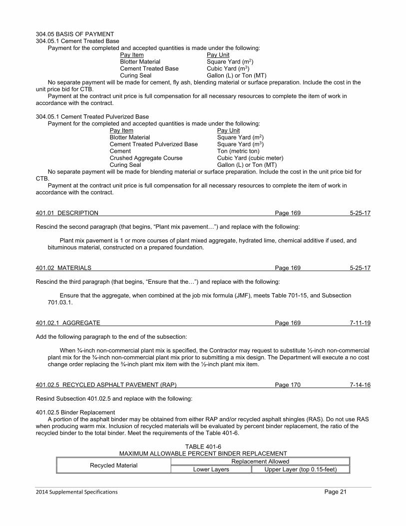
2014 Supplemental Specifications Page 21
304.05 BASIS OF PAYMENT 304.05.1 Cement Treated Base
Payment for the completed and accepted quantities is made under the following: Pay Item Pay Unit Blotter Material Square Yard (m2) Cement Treated Base Cubic Yard (m3) Curing Seal Gallon (L) or Ton (MT)
No separate payment will be made for cement, fly ash, blending material or surface preparation. Include the cost in the unit price bid for CTB.
Payment at the contract unit price is full compensation for all necessary resources to complete the item of work in accordance with the contract. 304.05.1 Cement Treated Pulverized Base
Payment for the completed and accepted quantities is made under the following: Pay Item Pay Unit Blotter Material Square Yard (m2) Cement Treated Pulverized Base Square Yard (m3) Cement Ton (metric ton) Crushed Aggregate Course Cubic Yard (cubic meter) Curing Seal Gallon (L) or Ton (MT)
No separate payment will be made for blending material or surface preparation. Include the cost in the unit price bid for CTB.
Payment at the contract unit price is full compensation for all necessary resources to complete the item of work in accordance with the contract. 401.01 DESCRIPTION Page 169 5-25-17 Rescind the second paragraph (that begins, “Plant mix pavement…”) and replace with the following:
Plant mix pavement is 1 or more courses of plant mixed aggregate, hydrated lime, chemical additive if used, and bituminous material, constructed on a prepared foundation.
401.02 MATERIALS Page 169 5-25-17 Rescind the third paragraph (that begins, “Ensure that the…”) and replace with the following:
Ensure that the aggregate, when combined at the job mix formula (JMF), meets Table 701-15, and Subsection 701.03.1.
401.02.1 AGGREGATE Page 169 7-11-19 Add the following paragraph to the end of the subsection:
When ¾-inch non-commercial plant mix is specified, the Contractor may request to substitute ½-inch non-commercial plant mix for the ¾-inch non-commercial plant mix prior to submitting a mix design. The Department will execute a no cost change order replacing the ¾-inch plant mix item with the ½-inch plant mix item.
401.02.5 RECYCLED ASPHALT PAVEMENT (RAP) Page 170 7-14-16 Resind Subsection 401.02.5 and replace with the following: 401.02.5 Binder Replacement
A portion of the asphalt binder may be obtained from either RAP and/or recycled asphalt shingles (RAS). Do not use RAS when producing warm mix. Inclusion of recycled materials will be evaluated by percent binder replacement, the ratio of the recycled binder to the total binder. Meet the requirements of the Table 401-6.
TABLE 401-6
MAXIMUM ALLOWABLE PERCENT BINDER REPLACEMENT
Recycled Material Replacement Allowed Lower Layers Upper Layer (top 0.15-feet)

2014 Supplemental Specifications Page 22
RAS (used alone) 15 15 RAP 35 25 RAP and RAS (combination)1 25 25 Note 1: When using RAS in combination with RAP, ensure the RAS does not exceed 3% by weight of the total aggregate blend.
If binder replacement is included in the job mix formula and the final mix, meet all of the plant mix requirements. Utilize separate stockpiles and feeds for each recycled component.
It is recommended that at least 2 separate RAP stockpiles be produced. Furnish RAS in accordance with AASHTO MP 23-145. The specific gravity of the RAS may be obtained in accordance
with AASHTO PP 78. If RAS is used, meet the requirements of Table 401-7:
TABLE 401-7 TABLE OF GRADATIONS - RAS
Percentage By Weight Passing Square Mesh Sieves
Sieve Size Percent Passing
⅜-inch (9.5 mm) 100 No. 4 (4.75 mm) 93
401.03 CONSTRUCTION REQUIREMENTS Page 170 5-25-17 Rescind the fourth paragraph (that begins, “For non-commercial mix …”) and replace with the following:
For non-commercial mix, set the initial job mix targets before producing more than 2000 tons (2000 MT) of plant mix surfacing. Plant mix produced prior to setting initial targets is defined as start-up mix. Furnish the Project Manager 1 copy of form CB30QA-VM (S) with the proposed job mix targets for VMA, VFA, VTM, and D/A. Once the job mix targets are set, Quality Assurance (QA) will be applied to all subsequent plant mix produced. No pay incentive will be applied to the plant mix until the targets are set. Produce start-up mix meeting the criteria listed in accordance with the Start-Up Job Mix Range in Table 701-18. A Hamburg wheel track test (Hamburg) will be performed in accordance with Subsection 401.03.2 when the produced mix does not meet all the criteria specified in accordance with the start-up job mix range in Table 701-18. Within the fifth paragraph, rescind the fourth sentence (that begins, “Submit to the…”) and replace with the following:
Submit to the Project Manager 1 signed copy of form CB30-QA-VM (S) with the revised job mix targets for VMA, VFA, VTM and D/A. 401.03.1 MIX DESIGN Page 171 9-20-18 Within the first paragraph, following the first sentence (that begins, “Submit to the…”) add the following sentences:
Use form MDT-MAT-009 as a mix design cover sheet. Ensure all fields are completed. The mix design and cover sheet may be submitted electronically. Mix designs submitted without the cover sheet or submitted with a cover sheet that doesn’t contain all the applicable information will be rejected. Within the first paragraph, rescind the eighth sentence (that begins, “For mix designs using…”) and replace with the following:
For mix designs using binder replacement, furnish the asphalt content and gradation of each recycled component and furnish the total asphalt content and Job Mix Formula gradation including the RAP/RAS. Rescind the second paragraph (that begins, “Furnish samples of…”) and third paragraph (that begins, “The Department has…”) and replace with the following:
Furnish samples of material from each stockpile. Ensure samples represent the stockpiles and mix design to be used on the project. Provide at least 800 pounds of aggregate, which can be appropriately proportioned to match the mix design. If the aggregate submitted cannot be appropriately proportioned to the submitted JMF, the mix design will be rejected and the mix design verification process will start over. A total weight of 600 pounds is allowed if the mix design includes Hamburg testing results. Furnish 5 gallons (19 L) of the specified asphalt binder or indicate consent to use binder of the same source and grade provided from the Department’s supply. Furnish 5 pounds of hydrated lime or indicate consent to use lime of the same source provided from the Department’s supply.
The Department has 30 calendar days from receipt of the mix design materials and signed mix design documents to review/verify the mix design. Mix design verification consists of:

2014 Supplemental Specifications Page 23
• Ensuring less than 13.0 mm of rut at 15,000 passes during Hamburg testing; • A review of the submitted mix design documents to ensure all applicable design and aggregate requirements
have been met; and, • Testing of the submitted aggregate for conformance with Subsection 701.03. Hamburg test results may be submitted with the mix design. Ensure Hamburg testing is done in accordance with MT
334. The Department reserves the right to verify any Hamburg results. Tensile strength ratio test results do not have to be submitted with the signed mix design documents but must be
received and reviewed before a mix design will be considered verified. Contract time will be extended for the actual contract time the Contractor’s paving start date was delayed, as verified by their most recent submitted schedule, and only for contract time assessed after the 30 day verification time frame. No additional compensation is allowed for these Department-caused delays. Contract time will not be extended if the delay occurs between November 1st and April 15th.
Rescind the fifth paragraph (that begins, “A change in…”) and sixth paragraph (that begins, “In lieu of…”) and replace with the following:
A change in the asphalt supplier or aggregate source(s) will not require a new mix design, provided no change in the established job mix targets is requested, and the aggregate and Hamburg requirements are met. If a change in the asphalt supplier or aggregate source is requested after mix design verification by the Department but before production begins, targets must be set before laydown operations begin and all mix will be considered production mix. During start up, establish job mix targets immediately if changing asphalt supplier or aggregate source prior to setting initial targets on non-commercial mix projects. For commercial mix, any mix produced after a change in supplier will be considered production mix and subject to full disincentives. Provide the apparent and bulk dry specific gravities and absorption for the aggregate, and the specific gravity for asphalt cement when there are changes in the source(s).
In lieu of developing a new mix design, a previous Department verified mix design may be requested for transfer. To be eligible for transfer, the transferred mix design must utilize the same material constituents, from the same sources, and in the same proportions as the original mix design. Any request for transfer must be made at least 10 business days in advance of paving. Mix design transfers will not be considered if the design traffic warrants different mix design criteria. Approval for transferring a mix design is at the discretion of the Department and may require Hamburg testing or aggregate consensus properties re-verification. Proposed transfers with variations to the original mix design such as asphalt supplier or other factors such as changes to the crushing operation which could create uncertainty in the performance of the mix design will be subject to re-verification testing. When submitting a request for a mix design transfer, furnish quantities from each stockpile to produce a 300-pound (136 kg) sample if the Department determines Hamburg testing re-verification is necessary. Submit form MDT-MAT-009 with any mix transfer request.
401.03.2 HAMBURG WHEEL TRACK TESTING (HAMBURG) Page 171 11-16-17 Rescind Subsection 401.03.2 and replace with the following: 401.03.2 Hamburg Wheel Track (Hamburg) Testing and Acceptance
A. Hamburg Testing. Furnish a sample of plant mix surfacing material for Hamburg acceptance after initial job mix targets have been established for non-commercial mix. Furnish additional samples as directed by the Project Manager. The Department may require Hamburg samples at any time. Hamburg samples may be run on the applicable gyratory pucks and/or in-place mix represented by the pucks. Hamburg test results for the initial target set will be furnished to the Contractor within 7 business days. Hamburg test results in all other cases will be furnished to the Contractor as soon as they are available.
If plant mix fails exceeds 13.0 mm of rut in 10,000 passes during production Hamburg testing, make adjustments to produce plant mix meeting the requirements specified in the contract. After a failing Hamburg no more than 300 tons (300 MT) of plant mix may be produced until passing Hamburg results are received.
When 2 consecutive Hamburg samples do not meet the requirements, suspend production and submit a revised mix design and samples for verification and Hamburg testing. The initial mix design requirements will be used for verification. Do not resume production until the revised mix design is verified and Hamburg mix design requirements are met.
Plant mix lots represented by samples that do not meet Hamburg specifications are not eligible for QA incentives including ride and density incentives.
Remove and replace any plant mix represented by a failing Hamburg test. Plant mix removal and replacement is at no cost to the Department.
B. Hamburg Acceptance. Plant mix removal and replacement is at no cost to the Department. 1) PG 70-XX. Plant mix exceeding 13.0 mm of rut depth within 10,000 passes during production Hamburg testing is
considered failing material. Remove and replace any plant mix represented by a failing Hamburg test. 2) All other PG Grades. The number of wheel passes reached when the rut depth reaches 13.0 mm will be used to
determine the pay factor. The pay factor for the material represented by each test is determined from the following tableTable 401-8:.

2014 Supplemental Specifications Page 24
TABLE 401-8 HAMBURG TESTING PAY FACTORS
PG 58-XX and 64-XX # of wheel passes Pay factor
x ≥ 10,000 PF = 1.0
10,000 > x ≥ 8,000 𝑃𝑃𝑃𝑃 = 1.00 −0.50(10000− 𝑥𝑥)
2000
x < 8,000 PF = 0, Remove and Replace 1 Note 1: In the areas listed below, material represented by Hamburg tests exceeding 13.0 mm of rut between 6,000 and 8,000 passes, may remain in place at a 0.5 pay factor: • Bicycle, pedestrian, or shared use (non-vehicular) paths • Roadway shoulders, only if the entire width of the paver pass occurred within the width of the
shoulder. • Lower layers below 0.25 feet from the finished surface of plant mix. Remove and replace plant mix exceeding 13.0 mm of rut in less than 6,000 passes.
The above exclusions do not apply if the entire thickness section of plant mix is not completed prior to winter
suspension. 401.03.3 TEST PROCEDURES Page 172 4-25-19 Replace MT 314 with AASHTO T 166. Add the following paragraph following the test procedures:
When material is tested in accordance with MT 332, if the height of gyratory specimens is out of tolerance, an evaluation will be conducted to determine if the specimen will be retained or discarded. The Department will check plant production information, test equipment, processes, calculations, etc. for issues. If a problem is noted in processes controlled by the Contractor, the test will be considered valid. If a problem is found with the testing or other Department process, or no issues with Contractor production are identified, the test will be redone on material from the same sample, if possible. If a non-correctable testing problem is found, the specimen will be discarded. 401.03.4(A) JOB MIX FORMULA Page 172 5-25-17 Within the first paragraph, rescind the first sentence (that begins, “Establish target asphalt…”) and replace with the following:
Establish target asphalt cement, warm mix additive content (if applicable), and aggregate gradation. 401.03.5 ACCEPTANCE COMMERCIAL PLANT MIX SURFACING Page 172 10-9-14 Rescind the second paragraph (that begins, “A $3.00/ton…”) and replace with the following:
For the first 1000 tons (1000 MT), a $3.00/ton maximum price reduction in the unit bid price for plant mix surfacing will be applied for any mix represented by a test not meeting the VMA, VFA, VTM, or D/A specified. A $3.00/ton price reduction ($9.00/ton maximum) in the unit bid price for plant mix surfacing will be applied to any subsequent mix for each test not meeting the VMA, VFA, VTM, or D/A specified. Price reductions will be assessed on the quantity of material represented by each failing sample. The quantity of material represented by each sample is the total tons of material produced divided by the total number of samples representing the material. 401.03.6 ACCEPTANCE OF NON-COMMERCIAL PLANT MIX SURFACING (QA) Page 173 8-6-15 Rescind the first paragraph of Subsection 401.03.6 (that begins, “The properties listed…”) and replace with the following:
For the start-up mix, a $3.00/ton price reduction ($9.00/ton maximum) in the unit bid price for plant mix surfacing will be applied for each test not meeting the VMA, VFA, VTM, or D/A specified. Price reductions will be assessed on the quantity of material represented by each failing sample. The quantity of material represented by each sample is the total tons of start-up mix produced divided by the total number of samples representing the material.
Once targets have been set, the properties listed in Table 701-18 for non-commercial plant mix are designated for acceptance on a lot-by-lot basis in accordance with Subsection 105.03.2. The pay factor in Table 401-1 is applied to plant mix surfacing lots for VMA, VFA, VTM and D/A. The asphalt content used for calculations is determined in accordance with MT

2014 Supplemental Specifications Page 25
319. The D/A is calculated in accordance with MT 319, and the gradation determined in accordance with MT 320 on the aggregate remaining after the ignition oven test. 401.03.17 TACK COAT Page 178 8-6-15 Rescind the second paragraph (that begins, “Apply tack coat on…”) and replace with the following:
Apply tack coat on aggregate treated surfaces, existing surfacing to be overlaid and between lifts when pavement is constructed in multiple lifts. 401.03.18 SURFACE CONDITIONS, WEATHER LIMITATIONS AND PAVING DATES Page 178 11-16-17 Within the second paragraph, rescind the first sentence (that begins, “Complete all sections…”) and replace with the following:
Complete all sections of plant mix surfacing, to be open to traffic during winter suspension, to the full plan width and thickness, excluding the seal and cover. 401.03.21 COMPACTION, COMPACTION CONTROL TESTING, Page 180 4-25-19
AND DENSITY ACCEPTANCE TESTING Rescind the fifth paragraph (that begins, “Provide core samples…”) and replace with the following:
Provide core samples of the compacted plant mix from the roadway. Core locations will be randomly selected based on the tons (MT) of mix placed. Core the locations selected after all rolling is complete and before the roadway is opened to traffic. The center of the core location will not be within 12 inches (305 mm) of unconfined longitudinal paving joints, 12 inches (305 mm) of a shoulder hinge point, or where the planned nominal thickness is less than 0.10-foot (30 mm). The center of the core locations for vertically confined longitudinal joints may be placed within 5 inches (125 mm) of the joint. The pavement density is determined from cores taken at randomly selected locations after all rolling is complete and before the roadway is open to traffic.
Within the seventh paragraph (that begins, “Take cores after…”) rescind the first sentence (that begins, “Take cores after…”). Replace MT 314 with AASHTO T 166. 401.03.23(A) RIDE SPECIFICATION Page 181 11-16-17 Rescind the first and second paragraphs and replace with the following:
A. Ride Specification. Construct all surfacing courses to provide completed plant mix pavements that meet surface smoothness and profile levels derived from the pre-pave IRI. Surface smoothness and surface profile will be analyzed from data collected by the Department using a Class I laser road profiler following Department procedures for profiler operations. The IRI will be measured in inches/mile, regardless of the unit of measure used on the contract. Projects with high pre-paving IRI value:
• Projects with an average pre-paving IRI value greater than or equal to 190 in/mi and 2 or more opportunities to improve the ride are considered a Category I project.
• Projects with an average pre-paving IRI value greater than or equal to 190 in/mi and one opportunity to improve the ride must have a post-paving IRI less than or equal to 50% of the pre-paving IRI. There is no pay adjustment factor based on smoothness; corrective action is required to produce a post-paving IRI less than or equal to 50% of the pre-paving IRI at Contractor expense.
Each opportunity to improve the ride is one of the following: • Placing a gravel base or surfacing course; • Placing plant mix base; • Placing cement treated base; • Placing pulverized plant mix surfacing; • Milling; • Hot or cold recycling (milling and laydown); or • Each full 0.10-foot (30 mm) increment for ⅜-inch (9.5 mm) aggregate mix, 0.12 foot (36 mm) increment for ½-
inch (12.5 mm) aggregate mix, and 0.15-foot (45 mm) increment for ¾-inch (19 mm) aggregate mix of new plant mix surfacing.
Target IRI values are determined by project category based on the opportunities for improving the ride, by the pre-paving IRI value, paving constraints or by a combination of these as follows:
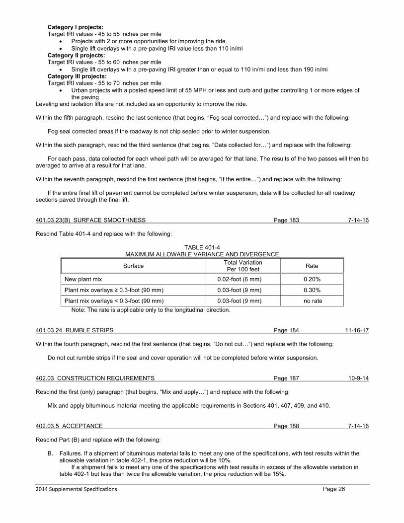
2014 Supplemental Specifications Page 26
Category I projects: Target IRI values - 45 to 55 inches per mile
• Projects with 2 or more opportunities for improving the ride. • Single lift overlays with a pre-paving IRI value less than 110 in/mi
Category II projects: Target IRI values - 55 to 60 inches per mile
• Single lift overlays with a pre-paving IRI greater than or equal to 110 in/mi and less than 190 in/mi Category III projects: Target IRI values - 55 to 70 inches per mile
• Urban projects with a posted speed limit of 55 MPH or less and curb and gutter controlling 1 or more edges of the paving
Leveling and isolation lifts are not included as an opportunity to improve the ride. Within the fifth paragraph, rescind the last sentence (that begins, “Fog seal corrected…”) and replace with the following:
Fog seal corrected areas if the roadway is not chip sealed prior to winter suspension. Within the sixth paragraph, rescind the third sentence (that begins, “Data collected for…”) and replace with the following:
For each pass, data collected for each wheel path will be averaged for that lane. The results of the two passes will then be averaged to arrive at a result for that lane. Within the seventh paragraph, rescind the first sentence (that begins, “If the entire…”) and replace with the following:
If the entire final lift of pavement cannot be completed before winter suspension, data will be collected for all roadway sections paved through the final lift. 401.03.23(B) SURFACE SMOOTHNESS Page 183 7-14-16 Rescind Table 401-4 and replace with the following:
TABLE 401-4 MAXIMUM ALLOWABLE VARIANCE AND DIVERGENCE
Surface Total Variation Per 100 feet Rate
New plant mix 0.02-foot (6 mm) 0.20%
Plant mix overlays ≥ 0.3-foot (90 mm) 0.03-foot (9 mm) 0.30%
Plant mix overlays < 0.3-foot (90 mm) 0.03-foot (9 mm) no rate Note: The rate is applicable only to the longitudinal direction.
401.03.24 RUMBLE STRIPS Page 184 11-16-17 Within the fourth paragraph, rescind the first sentence (that begins, “Do not cut…”) and replace with the following:
Do not cut rumble strips if the seal and cover operation will not be completed before winter suspension. 402.03 CONSTRUCTION REQUIREMENTS Page 187 10-9-14 Rescind the first (only) paragraph (that begins, “Mix and apply…”) and replace with the following:
Mix and apply bituminous material meeting the applicable requirements in Sections 401, 407, 409, and 410. 402.03.5 ACCEPTANCE Page 188 7-14-16 Rescind Part (B) and replace with the following:
B. Failures. If a shipment of bituminous material fails to meet any one of the specifications, with test results within the allowable variation in table 402-1, the price reduction will be 10%.
If a shipment fails to meet any one of the specifications with test results in excess of the allowable variation in table 402-1 but less than twice the allowable variation, the price reduction will be 15%.
2014 Supplemental Specifications Page 27
If a shipment fails to meet any one of the specifications with test results in excess of twice the allowable variation in table 402-1 but less than three times the allowable variation, the price reduction will be 25%.
If a shipment fails to meet any one of the specifications with test results in excess of three times the allowable variation in table 402-1, the Project Manager may reject the material and require its removal from the work, or the Project Manager may accept the material at a 50% price reduction.
The cost of the bituminous material for calculating price reductions is the material’s contract unit price. The price reduction percentage will be based on the unit price bid for bituminous material when it is paid as a separate item or the invoice price when it is part of a bid item.
If a shipment fails more than one of the specifications, the failure causing the largest percentage price reduction is assessed.
Within Table 402-1, Schedule of Tolerances, rescind the term “Allowable Variation” from within the heading and replace with “Variation”. 402.04 METHOD OF MEASURMENT Page 192 10-9-14 Within the sixth (last) paragraph, rescind the first sentence (that begins, “Use flow rate…”) and replace with the following:
Use flow rate meters in accordance with Subsection 401.03.12, to measure the material. 403.02 MATERIALS Page 193 8-6-15 Rescind Subsection 403.02(A) and replace with the following:
A. Crack Sealant. Use a sealant that is listed on the QPL and in accordance with Subsection 707.01. Rescind Subsection 403.02(B) and replace with the following:
B. Backer Rod. Furnish backer rod that is listed on the QPL. Furnish backer rod in accordance with ASTM D5249, Type 1. The backer rod used must be compatible with the crack sealant placement temperature and sized for cracks in accordance with Subsection 403.03.4.
403.03.4 SEALING Page 194 12-11-14 Within the first paragraph, rescind the third (last) sentence (that begins, “Do not rout further…”) and replace with the following:
Place sealant material within 24 hours of routing. 409.02.2 BITUMINOUS MATERIAL Page 197 5-25-17 Rescind the first (only sentence (that begins, “Furnish material in…” and replace with the following:
Furnish material in accordance with Section 702. 409.03.1 SAMPLING, TESTING, AND ACCEPTANCE Page 197 4-25-19 Replace MT 217 with AASHTO T 335. 409.03.3 SEAL COAT LIMITATIONS Page 198 2-26-15 Add the following to the end of the list:
7. Do not apply bituminous material within 72 hours of performing crack sealing. 409.03.10 SWEEPING AND BROOMING Page 199 7-14-16 Rescind the first paragraph (that begins, “Provide a roadway…”) and replace with the following:

2014 Supplemental Specifications Page 28
Provide a roadway free of loose cover material. In curb and gutter sections, remove and dispose of all loose cover material from the roadway and sidewalks. Do not allow material to enter any storm drain system or aquatic resource. In guardrail sections, do not allow loose cover material to accumulate beneath the rail.
Rescind Subsection 409.03.10(B) and replace with the following:
B. Final Sweeping and Brooming. Perform final sweeping and brooming operations to remove excess loose material no sooner than 5 calendar days before final pavement markings. Coordinate with the Project Manager to ensure Final Sweeping and Brooming is necessary. Provide traffic control in accordance with Section 618.
501 PORTLAND CEMENT CONCRETE PAVEMENT Page 209 *11-14-19 Rescind Section 501 and replace with the following:
SECTION 501 PORTLAND CEMENT
CONCRETE PAVEMENT
501.01 DESCRIPTION This work is the construction of PCCP on a prepared subgrade or base course.
501.02 MATERIALS 501.02.1 Concrete
Furnish concrete in accordance with Section 551 for Class Pave concrete. A. Cement. Furnish Type I, II, V, IS, IP, or IT portland cement listed on the QPL, in accordance with Subsection
551.02.1. B. Aggregate. Use optimized gradations unless otherwise specified. Furnish aggregate in accordance with Subsection
701.01.2 having a wear factor not exceeding 30%. 501.02.2 Reinforcing Steel
Steel-wire fabric and steel bar mat sizes and dimensions are specified in the contract. Furnish steel-wire fabric reinforcement in flat sheets. Furnish bar mats and bars of structural or intermediate grade, as specified in the contract. Furnish all reinforcing steel in accordance with Section 555 and Subsection 711.01.
501.02.3 Dowel Bars and Sleeves Furnish Grade 40 or 60 plain round dowel bars in accordance with AASHTO M 31. Epoxy coat the dowel bars in accordance with AASHTO M 254 at 10 ±2 mils. Ensure the bars are coated by an applicator
plant listed on the QPL and certified under the CRSI epoxy coating plant certification program for fusion-bonded epoxy applicator plants.
Do not use bars having burrs or other deformation that restrict slipping in the concrete. Provide dowels with a factory applied petroleum, paraffin-based lubricant with a manufacturer certified use as a bond
breaker. Furnish sleeves for dowel bars meeting the contract requirements.
501.02.4 Tie Bars Furnish Grade 40 or 60 deformed steel bars in accordance with AASHTO M 31 and Subsection 711.01.2. The length,
size, and spacing of the bars are specified in the contract. 501.02.5 Expansion Joint Filler and Joint Sealing Material
Furnish expansion joint filler and joint sealing material listed on the QPL and in accordance with Subsection 707.01. 501.02.6 Curing Compound
Furnish Type 2 curing compound listed on the Department’s QPL and in accordance with Subsection 717.01.3. 501.03 CONSTRUCTION REQUIREMENTS 501.03.1 Equipment
A. General. Do not begin paving operations until all equipment and tools for the pavement construction are available at the site. Use handling, batching, mixing, and concrete transporting equipment in accordance with Section 551 and the
following. Use batch plants that proportion aggregates and cement by weight using automatic and interlocked proportioning
devices. For placements up to 1000 square yards (836 m2), approval may be requested to use manual plants. Use hauling equipment in accordance with Subsection 551.03.4. Remove and dispose of concrete remaining in haul
units before reloading with fresh concrete. If using non-agitating hauling equipment, ensure smooth, mortar-tight metal bodies that completely discharge the concrete at a uniform rate without segregation. Provide covers when necessary to prevent the concrete from drying out or being exposed to weather-related moisture. Plant-mixed concrete may be transported in non-agitating vehicles provided that concrete is in a workable condition when placed and:
Discharge is completed within 45 minutes after the introduction of mixing water to the cement and aggregates, or 1. Discharge is completed within 60 minutes after the introduction of mixing water to the cement and aggregates,
provided the concrete mix temperature is 70°F (21 °C) or below during placement, or

2014 Supplemental Specifications Page 29
2. Discharge is completed within 60 minutes after the introduction of mixing water to the cement and aggregates, provided the mix contains an approved set retarder used in accordance with subsection 551.03.3.
B. Slip-Form Paver. Use a self-propelled slip-form paver capable of consolidating, screeding, and float-finishing freshly placed concrete in one complete pass of the machine for the required thickness. Use machines equipped to internally vibrate the concrete for the full width and depth placed in a single pass as required to produce a dense, homogeneous pavement. Ensure the rate of vibration of each vibrating unit is at least 7,500 cycles per minute. Ensure the vibration is sufficient to be perceptible on the surface of the concrete along the entire length of the vibrating unit and for a distance of at least 1-foot. Vary the frequency or amplitude of vibration proportionately with the rate of travel to result in a uniform density and air content. Ensure the paving machine is equipped with a tachometer or other suitable device for measuring and indicating the actual frequency of vibrations.
Ensure equipment can produce the frequency and amplitude the paver manufacturer recommends for the placement at hand.
C. Stationary Side Forms. Use clean, straight, un-warped steel forms with a vertical face of appropriate for the depth of placement. Ensure that forms have side and base supports capable of supporting finishing equipment and are sufficiently strong to resist concrete pressure without bulging.
Wood or plastic forms for forming fillets, widened areas in intersections, curves less than 100-foot radius (30 m), and in other engineer-approved locations.
D. Finishing Equipment for Stationary Side Forms. Bridge Deck Finishing Equipment. Use transverse-finishing rotating drum bridge deck finishing machines Truss Screeds. Use air-vibrated or mechanically-vibrated truss screeds designed for and capable of striking off
the placement. Joint Sawing Equipment. Provide wet-cut saws for joint establishment in the all concrete. When using early-entry saws, use saw blades and skid plates specifically designed for the type coarse
aggregate used in the concrete in accordance with the saw manufacturer’s recommendation. F. Hand Finishing Tools. Use aluminum, magnesium, or wooden hand finishing tools. Do not use steel had finishing
tools. 501.03.2 Pre-paving Conference
Schedule a pre-paving conference to be held at least 72 hours before paving starts. Submit an agenda to include equipment, construction methods, specification requirements, and lines of communication. The conference must include the foreman, subcontractors/suppliers, other Contractor personnel that will supervise the
concrete paving operations, and key Department inspection personnel. 501.03.3 Mixing
Mix concrete in accordance with Subsection 551.03.3. 501.03.4 Transporting Concrete
Transport concrete in equipment in accordance with Subsections 501.03.1 and 551.03.4. 501.03.5 Placing and Finishing Concrete
Concrete will be tested and accepted in accordance with Section 551. A. Slip-form Method. Uniformly distribute concrete into final position by a self-propelled slip-form paver without delay.
Regulate the alignment and elevation of the paver from outside reference lines established for this purpose, or by an electronic control system capable of controlling the line and grade within required tolerances. Ensure the paver vibrates the concrete for the full width and depth of the strip of pavement being placed and the vibration is adequate to provide a consistency of concrete that stands normal to the surface with sharp well-defined edges. Ensure the sliding forms are rigidly held together laterally to prevent spreading.
Ensure the plastic concrete is effectively consolidated by internal vibration with transverse vibrating units for the full width of pavement and/or a series of equally spaced longitudinal vibrating units. The space from the outer edge of the pavement to the outer longitudinal unit must not exceed 9 inches (230 mm). The spacing of internal units must be uniform and not exceed 18 inches (455 mm).
The term internal vibration means vibration by vibrating units located within the specified thickness of pavement section.
Hold the concrete at a uniform consistency. Operate the slip-form paver with as nearly a continuous forward movement as possible. Coordinate all operations of mixing, delivering, and spreading concrete to provide uniform progress with stopping and starting of the paver held to a minimum. If, for any reason, it is necessary to stop the forward movement of the paver, the vibratory and tamping elements shall also be stopped immediately. Do not apply tractive force to the machine, except that which is controlled from the machine.
When concrete is being placed adjacent to an existing pavement, equip that part of the equipment which is supported on the existing pavement with protective pads on crawler tracks or rubber-tired wheels on which the bearing surface is offset to run a sufficient distance from the edge of the pavement to avoid breaking the pavement edge.
B. Stationary Side Form Method. Before placing side forms, ensure the underlying material is at the proper grade. Side forms shall be placed to the required grade and alignment of the edge of the finished pavement. Wood wedges may be used to adjust the form elevation provided they do not extend into the concrete. The forms shall be firmly supported during the entire operation of placing, compacting, and finishing the pavement.
Drill forms in advance of being placed to line and grade to accommodate tie bars where these are specified. Ensure side forms remain in place at least 12 hours after the concrete has been placed, and in all cases until the
edge of the pavement no longer requires the protection of the forms. Apply curing compound to the concrete immediately after the forms are removed.
2014 Supplemental Specifications Page 30
Thoroughly clean and oil side forms each time they are used and before concrete is placed against them. Spread, screed, shape, and consolidate concrete by one or more self-propelled machines. Ensure these
machines uniformly distribute and consolidate concrete without segregation so that completed pavement will conform to required cross section with a minimum of handwork.
Ensure the number and capacity of machines furnished is adequate to perform the work required at a rate equal to that of concrete delivery.
Effectively consolidate concrete for the full paving width by means of surface vibrators, in combination with internal vibrators, or by some other method of consolidation that produces equivalent results without segregation.
When vibrators are used to consolidate concrete, ensure the rate of vibration is at least 3,500 cycles per minute for surface vibrators and is at least 7,000 cycles per minute for internal vibrators. Ensure the amplitude of vibration is sufficient to be perceptible on the surface of the concrete more than 1-foot from the vibrating element. Furnish a suitable device for measuring and indicating frequency of vibration. Connect power to vibrators so that vibration ceases when forward or backward motion of the machine is stopped.
C. Final Surface Finish. Hand-float the surface only as needed to produce a uniform surface and sharp corners. Adding finishing water to unfinished concrete is prohibited. Do not use excess mortar to build up slab edges or round the slab corners. Before the concrete’s initial set, work the pavement edges along each side of transverse isolation joints, transverse construction joints, and fixed forms to produce a ¼-inch (6 mm) continuous radius and a smooth, dense mortar finish. Check the surface of the fresh concrete with a long-handled straightedge that is 10 feet (3 m) or longer. Remove high areas indicated by the straightedge.
D. Texturing. Longitudinally tine all pavements unless transverse tining is allowed as described below. In advance of curing operations, where longitudinal tining is required, complete initial and final texturing on the pavement. Perform initial texturing with a burlap drag or broom device that produces striations parallel with the centerline. Perform final texturing with a wire comb tine device that produces grooves parallel with the centerline. Operate the wire comb tine device within 5 inches (125 mm), but not closer than 3 inches (75 mm), of pavement edges.
Ensure burlap drags, brooms, and tine devices are installed on self-propelled equipment having external alignment control. Ensure the area of burlap in contact with the pavement surface is always constant. Include positive elevation control on broom and tine devices. Maintain downward pressure on pavement surface during texturing to achieve uniform texturing without measurable variations in pavement profile. Maintain constant travel speed during texturing. Ensure the wire comb of the final texturing device is rectangular in cross section, 3/32 to 1/8-inch wide, on ¾-inch centers, ± 1/8-inch, and of sufficient length, thickness, and resilience to form grooves approximately 1/8-inch deep in the fresh concrete surface. Ensure final texture is uniform in appearance with substantially all the grooves having a depth between 1/16 and 3/16-inch.
On projects requiring less than 1,000 square yards (836 m2) of cement concrete pavement, for irregular areas or areas not accessible to slip-form pavers, the surface finish may be either longitudinal tined or transverse tined. Complete transverse tining by texturing with a wire comb perpendicular to the centerline. Ensure the wire comb of the final texturing device is rectangular in cross section, 3/32 to 1/8-inch wide, on ¾-inch centers, ± 1/8-inch, and of sufficient length, thickness, and resilience to form grooves approximately 1/8-inch deep in the fresh concrete surface. Ensure final texture is uniform in appearance with substantially all the grooves having a depth between 1/16 and 3/16-inch. Ensure the elements of the wire comb as nearly perpendicular to the concrete surface as is practical, to eliminate dragging the mortar.
Regardless of the surface finish, if the pavement has a raised curb end the texturing 2 feet (610 mm) from the curb line.
501.03.6 Protection of Concrete from Adverse Weather Maintain materials at the project site to protect all un-hardened concrete surfaces from rain, hail, or snow. When adverse weather appears imminent, stop paving operations and cover all surfaces of the un-hardened concrete
with the protective covering. Do not finish rainwater, hail, or snow into the concrete surface. 501.03.7 Evaluation and Repair of Weather -Damaged Concrete Cease operation when rain is threatening. Remove, replace, or repair any pavement damaged by rain, hail, or snow as determined by the Project Manager. Pavement is considered damaged when rain, hail, or snow leaves noticeable texture on the surface.
All protective, remedial, and corrective work to produce acceptable pavement is at Contractor expense. 501.03.8 Curing
Immediately after finishing operations have been completed and marring of the concrete will not occur, cure the entire surface of the newly placed concrete in accordance with Subsection 551.03.7 and one of the following methods.
A. Membrane. Before application, agitate the curing compound as received in the shipping container to obtain a homogenous mixture. Protect membrane curing compounds from freezing. Handle and apply the membrane curing compound in accordance with the manufacturer’s recommendations and the following: 1. Apply compound to the entire area of the exposed surface of the concrete with an approved mechanical spray
machine at a rate of one gallon to not more than 150-square feet (14 m2). 2. Apply curing compound homogeneously to provide a uniform, solid, white opaque coverage on all exposed
concrete surfaces (equal to a white sheet of typing paper) at the time of application. 3. Immediately re-apply compound to damaged areas protected for less than 72 hours by spraying. 4. If the Project Manager determines that the initial or corrective spraying result in unsatisfactory curing, the Project
Manager may require the Contractor to use the White Polyethylene Sheeting method, at no additional cost to the Department.

2014 Supplemental Specifications Page 31
Use a fully automatic, self-propelled mechanical power sprayer to apply the curing compound in accordance with the following:
1. Operate the equipment to direct the curing compound to the surface from two different lateral directions. 2. Do not allow the sprayer to ride on the pavement surface. 3. Ensure the sprayer covers the entire lane width and atomizes the curing compound. 4. If puddling, dripping, or non-uniform application occurs, suspend the operation to perform corrections as approved by
the Project Manager. 5. Ensure the sprayer is equipped with the following:
a. A re-circulating bypass system that provides for continuous agitation of the reservoir material, b. Separate filters for the hose and nozzle, c. Check valve nozzles, d. Multiple or adjustable nozzle system that provides for variable spray patterns, e. A shield to control loss of material by wind action, and f. A spray-bar drive system that operates independently of the wheels or track drive system.
For pavements less than 1000 square yards (836 m2) and for irregular or narrow surfaces, submit a curing plan to the Project Manager for approval including equipment proposed for use.
Do not apply curing compound to the inside faces of joints to be sealed. Do not apply curing compound during rain. Have enough material on the project to immediately suspend
membrane curing and begin polyethylene sheeting in accordance with Subsection 501.03.11(B). Cover all concrete previously placed that is subject to damage or loss of curing compound. Repair all concrete damaged by rain to the Project Mangers approval and at no cost to the Department.
B. White Polyethylene Sheeting. Furnish sheeting in accordance with Subsection 717.01.5. Place sheeting over the pavement immediately after finishing operations are completed.
Place the sheeting so that individual sheets cover the entire pavement width and overlap longitudinally a minimum of 2 feet (610 mm). Ensure the lapped areas are held in close contact with the pavement by weighting sufficiently to prevent movement by the wind. Extend the sheeting downward to cover the edges of the pavement and secure to the subgrade. Cover any holes or exposed concrete immediately. Maintain the sheeting against injury and ensure complete coverage until the pavement has reached a minimum compressive strength of 2,500 psi.
C. Water Cure. Water cure in accordance with Subsection 551.03.7(A) until the pavement has reached a minimum compressive strength of 2,500 psi.
501.03.9 Handling and Placing Reinforcement Keep reinforcing steel clean, rust free, straight and distortion free, placed and held in position as specified. Store reinforcing steel out of the weather, distributing only the steel needed for immediate placing within the work. Assemble and place reinforcement for bar mats as specified. Maintain bar mat placement during concreting operations.
Tie all intersections. Lap all adjacent ends at least 40 bar diameters. 501.03.10 Joints
Make transverse construction joints as detailed in the contract, at the end of each day’s run, or where concrete work is interrupted for more than 1 hour.
A. Sawing Joints. Saw joints in a single cutting operation for a specific joint. Make saw cuts true to line and to the dimensions shown in the contract. Begin joint sawing as soon as the concrete has hardened sufficiently to permit sawing without raveling or moving of aggregate. Saw joints before uncontrolled cracking takes place. Control joints may be sawed by any saw designed for concrete sawing. If necessary, use continuous sawing operations regardless of weather or daylight conditions. Discontinue sawing a joint if a crack develops ahead of the saw.
A heavy span saw which is supported on the new pavement is not allowed for sawing pavements and concrete overlays less than 7 inches (175 mm) thick. If the pavement has been covered or protected due to cold weather, rain, or snow, saw joints by conventional saw equipment only.
Saw joints requiring compression sealant materials to be installed so that the compression sealant material can be installed and function correctly.
Repair uncontrolled cracking or random transverse cracking at no additional cost to the Department. Use repair methods approved by the Project Manager.
B. Expansion Joints. Install preformed joint material perpendicular to the pavement surface. Ensure that the joint material remains in proper position. Set reference stakes or markers showing joint location prior to placing concrete adjacent to the joint. After the mechanical finishing equipment has passed over the joint, check the joint for movement. If movement in excess of ½-inch has occurred, immediately correct the installation to its intended position. After the surface finishing has been completed, edge the joint as shown in the contract documents with minimum disturbance to the adjacent concrete.
C. Sealing Joints. Seal joints as designated in the contract before any portion of the pavement is opened to the traffic, including construction traffic. Saw or prepare joint openings to the designated dimensions. Clean the joint opening and seal with material in accordance with Subsection 501.02.5.
Within 3 hours after a joint has been wet sawed to the finished dimension, flush the wet sawing residue away from the sawed faces using a high-pressure water blast operating with at least 1000 pounds per square inch. Within 3 hours after the joint has been dry sawed to the finished dimension, blow the dry sawing residue from the joint. Use air compressors that provide moisture and oil free compressed air.
Immediately prior to installation of sealant, clean joints with an air blast. Do not perform sealing until visual examination verifies the joint surfaces appear dry, and clear of dust and contamination. Prepare joint sealer and install in the joint and to the proper level as shown in the contract and as recommended by the manufacturer. Heat hot poured

2014 Supplemental Specifications Page 32
sealers in a thermostatically controlled heating kettle. Heat the material to the temperature required for use, but not above that recommended by the manufacturer. After sealing, remove excess sealer from the pavement surface.
Place joint sealer only when the pavement and ambient air temperatures are 40°F (4°C) or above. When near this minimum, additional air blasting or drying time, or both, may be necessary to ensure a satisfactory bond to the joint faces. When this sealer cannot be properly placed due to weather/seasonal limitation, submit a joint construction plan and sealing details to the Project Manager for approval before commencing paving. Delay the cleaning, sealing, and, if required, resawing of joints until the following spring. This delay requires the Engineer’s approval.
When surface correction is required, repair seals damaged from the corrective work. Joint preparation, cleaning, and sealing may be delayed until after corrective work, provided the pavement is not opened to traffic before corrective work is performed.
The Project Manager may limit the wheel loads and axle loads of equipment operating on the pavement during preparation, cleaning, and sealing operations, if prior to the age and strength specified in Subsection 501.03.16.
D. Alternative Joint Layout. Submit an alternate plan for longitudinal and transverse joint layout with details that are determined by Contractor sequencing to the Project Manager for approval a minimum of 15 business days before the start of paving work.
Space the transverse joints not less than 10 feet (3 m) and not more than 15 feet (4.5 m). Space longitudinal joints not further than 13 feet (4 m) and as close to lane lines as possible. Skew longitudinal lines along mainline to match lane lines ahead.
Construct transverse joints at a 90° angle to the centerline. Continue transverse joints through the curb. Skew longitudinal and transverse joints to intersect all manholes, boxes, and inlets. The angle of joint intersection or between joints and a free edge must not be less than 60°. Space joint offsets not less than 18 inches (455 mm).
501.03.11 Surface Test Test pavement surfaces in accordance with the following criteria using the straightedge method.
• Sections less than 300 feet (91.5 m) in length. • Sections within 50 feet (15.2 m) of existing pavements or bridge ends. • Sections within 50 feet (15.2 m) of intersections requiring warping to match side streets. • Sections having horizontal curves with a centerline radius less than 1000 feet (305 m) and the superelevation
transitions of those curves. • Sections having vertical curves with L/A (K-value) less than 100 where L is the length of the curve in feet and A
is the grade change in percent (L/A less than 30.5 where L is in meters). Test all other surfaces in accordance with Subsection 501.03.14(B). A. Straightedge. Measure surface smoothness of travel lanes not subject to MRI testing with a 10- foot straightedge.
Ensure the completed surface of the wearing course does not vary more than 1/8-inch from the lower edge of a 10-foot straightedge placed on the surface parallel to the centerline.
Measure smoothness perpendicular to the centerline with a 10-foot straightedge across all lanes with the same cross slope, including shoulders when composed of cement concrete pavement. Discontinue the overlapping 10-foot straightedge measurement at a point 6 inches (150 mm) from the most extreme outside edge of the finished pavement. Ensure the completed surface of the wearing course does not vary more than ¼-inch from the lower edge of a 10-foot straightedge placed on the surface perpendicular to the centerline. Correct any deviations in excess of the above tolerances.
Where the grinding methods would result in an unsatisfactory surface or in a slab thickness less than specified, the affected pavement may require an adjustment in the contract unit price or removal and replacement in accordance with Subsection 501.03.20.
B. Ride Specification. Pavement surface smoothness for this project includes International Roughness Index (IRI) testing. Perform IRI testing on each through lane, climbing lane, ramp, and passing lane, greater than 0.2 mile in length. These sections will be subject to incentive/disincentive adjustments. Evaluate ride quality using the Mean Roughness Index (MRI) calculated by averaging the IRI data for the left and right wheel path within the section.
Shoulders, tapers, and other areas not included in MRI testing will not be subject to incentive adjustments. All work is subject to parallel and transverse 10-foot straightedge requirements, corrective work and disincentive adjustments.
Operate the inertial profiler in accordance with AASHTO R 57. Collect two longitudinal traces, one in each wheel path. Collect profile data after completion of all concrete paving on the project in a continuous pass including areas excluded from pay adjustments. Provide notice to the Project Manager at least 7 calendar days prior to testing.
Within 30 calendar days after the Contractor’s testing, the Department may perform verification testing. If the verification testing shows a difference in MRI greater than the percentages shown in Table 2 of AASHTO R 54 the following resolution process will be followed: 1. The profiles, equipment and procedures will be evaluated to determine the cause of the difference. 2. If the cause of the discrepancy cannot be resolved, coordinate retesting with both profilers at a mutually agreed
upon time. The two profilers will test the section within 30 minutes of each other. If the retest shows a difference in MRI equal or greater than the percentages shown in Table 2 of AASHTO R 54 the Engineer’s test results will be used to establish pay adjustments. Evaluate profiles for acceptance, incentive payments, disincentive payments, or corrective action using the
current version of ProVAL and provide the results including the profile data in unfiltered electronic Engineering Research Division (ERD) file format to the Project Manager within 2 business days of completing testing each section of pavement. If the profile data files are created using an export option in the manufacturer’s software where filter settings can be specified, use the filter settings that were used to create data files for certification.

2014 Supplemental Specifications Page 33
Analyze the entire profile. Exclude any areas specifically identified in the Contract. Exclude from the analysis the first 50 feet after the start of the paving operations and last 50 feet prior to the end of the paving operation, the first 50 feet (15 m) on either side of bridge structures and bridge approach slab. Report the MRI results in inches per mile for each 52.8-foot (16 m) section and horizontal distance measurements in project stationing to the nearest foot. Include pay adjustments in the results. The Project Manager will verify the analysis.
Corrective work for pavement smoothness may be taken by the Contractor prior to MRI testing. After completion of the MRI testing, measure the smoothness of each 52.8- foot (16 m) section with an MRI greater than 125 inches per mile with a 10-foot straightedge within 14 calendar days or as allowed by the Project Manager. Identify all locations that require corrective work and provide the straight edge measurements at each location that exceeds the allowable limit to the Project Manager. If all measurements in a 52.8-foot (16 m) section comply with smoothness requirements, provide the maximum measurement to the Project Manager and a statement that corrective work is not required. Corrective work is required for pavement identified by the Contractor or Department that does not meet the following requirements: 1. The completed surface is uniform in texture, smooth, uniform as to crown and grade, and free from defects of all
kinds. 2. The completed surface does not vary more than ¼ inch from the lower edge of a 10-foot straightedge placed on
the surface parallel to the centerline. 3. The completed surface does vary not more than ¼ inch in 10 feet (3 m) from the rate of transverse slope shown
in the contract. Complete all corrective work at no additional expense to the Department, including traffic control. Do not begin
corrective work until the concrete has reached design strength. Repair pavement by one or more of the following methods: 1. Diamond grinding; ensure repairs do not reduce pavement thickness by more than ¼ inch less than the
thickness shown in the contract. When required by the Project Manager, verify the thickness of the concrete pavement by coring. Thickness reduction due to corrective work will not be included in thickness measurements for calculating the Thickness Deficiency in Subsection 501.03.20.
2. Removal and replacement. 3. By other method allowed by the Project Manager.
Check the repaired area by the Contractor with a 10-foot straightedge to ensure it no longer requires corrective work. With concurrence of the Project Manager an inertial profiler may be used in place of the 10-foot straight edge.
501.03.12 Correcting Spall and Cracks Remove and replace pavement slabs cracked through the full depth into 3 or more parts. Repair pavement slabs containing a single diagonal crack intersecting the transverse and longitudinal joints within ⅓ of
the width and length of the slab from the corner by removing and replacing the smaller portion of the slab. Repair broken slabs as directed.
Groove and seal random cracks that penetrate the full depth of the pavement. Groove the top of the crack to ¾-inch (19 mm) minimum depth and a width between ⅜ to ⅝-inch (10-16 mm) using an approved grooving machine. Use a vertical rotary-cutting machine that can follow the crack path and widen the top of the crack to the required section without spalling or damaging the concrete. Remove all loose and fractured concrete, and thoroughly clean and seal the groove with the sealant specified in the contract.
The Project Manager will determine what random cracks are tight, don’t penetrate the full depth of the pavement and will be left undisturbed. When requested by the Project Manager, determine the crack depth penetration by drilling and inspecting cores at Contractor expense.
When a transverse random crack terminates in or crosses a transverse contraction joint, fill the un-cracked portion of the joint with epoxy-resin mortar or grout, and route and seal the crack.
When a transverse random crack nearly parallels the planned contraction joint and is within 5 feet (1.5 m) from a contraction joint, route, seal, and fill the crack with epoxy-resin grout or mortar.
When a transverse random crack is more than 5 feet (1.5 m) from the nearest contraction joint in the pavement, seal both the joint and the crack. Thoroughly clean the joints before filling with epoxy-resin mortar or grout.
Repair spalls by making a saw cut at least 1-inch (25 mm) outside the spalled area and to a minimum depth of 2 inches (50 mm). When the spalled area abuts a joint, make a saw-cut 2 inches (50 mm) deep or 1⁄6 the slab thickness, whichever is greater. Chip out the concrete between the saw cut and the joint or primary crack to solid concrete. Thoroughly clean the resulting cavity of all loose material. Apply a prime coat of epoxy-resin binder to the dry, cleaned surface of all cavity sides, except the working joint faces to be retained. Apply the prime coat by scrubbing it into the surface with a stiff bristle brush. Place hydraulic cement concrete or epoxy-resin concrete or mortar immediately following the prime coat application.
For spalled areas abutting working joints or working cracks penetrating full depth, place an insert or other bond breaker to maintain the joint or crack during the patch repair. 501.03.13 Opening to Traffic
Traffic and Contractor’s vehicles and equipment are prohibited on the concrete until one of the following test results indicate the concrete has achieved strength. Joint sawing and sealing equipment are allowed with the Project Manager’s approval
A. Flex Beam Method. Prepare the concrete flex beams in accordance with MT 101 and test for modulus of rupture using AASHTO T 97.
One test set consists of 3 beams. Take the concrete for the test beams from different concrete batches for each 2,500 square yards (2,100 m2) of concrete pavement and make at least 2 sets per day. Test the beam sets for modulus of rupture. Cure the test beams under the same environmental conditions as the pavement they represent.
2014 Supplemental Specifications Page 34
The pavement, represented by the beams, may be opened to traffic when the average modulus of rupture of the set exceeds 350 psi (2,415 kPa) and no individual beam’s modulus of rupture is less than 300 psi (2,070 kPa).
The Contractor may select the time for testing the beams. Test the flex beams on or near the project, using Contractor furnished equipment and with a Department Inspector witnessing the tests.
Include all costs to make, cure and test the flex beams in the contract unit price for PCCP. B. Maturity Meter Method. Prepare concrete flex beams or compressive test cylinders to validate the maturity meter
performance curves. Furnish the Project Manager the maturity-strength relationship and maturity curves along with supporting data for verification. Maturity-strength relationship must indicate compressive strengths of 2500 psi or greater. Develop the maturity meter index curves before construction has commenced.
Determine the time for testing flex beams. Furnish suitable testing equipment. The pavement may be opened to traffic and construction equipment, with Project Manager’s approval, when the
maturity meter readings reflect target values have been met. Furnish all equipment, including maturity meter, thermocouples, wire, and a qualified technician to monitor the
maturity meter system. C. Concrete Test Cylinder Method. Prepare concrete test cylinders according to MT 101 and AASHTO R 60, and test for
compressive strength according to AASHTO T 22. Make a minimum of one set of three compressive test cylinders, sampled from random locations, for each 2,500
square yards (square meters) of concrete pavement but not less than two sets per day. Test compressive test cylinders in sets of three for compressive strength. Cure test cylinders under the same conditions as the pavement they represent.
The pavement may be opened to traffic and construction equipment, with Project Manager’s approval, when the average compressive strength of a set of test cylinders is 2500 psi (17,237 kPa) or greater with no single test less than 2,000 psi (13,790 kPa).
Determine the time for testing cylinders. Furnish suitable equipment and test compressive cylinders on or near the project.
Opening to traffic does not constitute a final acceptance of the pavement. The pavement is accepted upon confirmation of the 28-day flexural strength. Repair all concrete damaged prior to the final acceptance at Contractor expense. 501.03.14 Integral Curb
Construct the curb monolithically with the pavement. Construct the inside face of the curb true to the lines and grades in the contract using the finish specified for the concrete
pavement, including longitudinal floating and burlap drag finishing. Test the surface for longitudinal trueness with a straightedge while the concrete is still plastic. Meet the same surface
requirements specified for the concrete pavement. Continue concrete pavement joints through the integral curb at the same locations, of the same type, and constructed in
the same manner. Cure the integral curb as specified for concrete pavement.
501.03.15 Weather and Night Limitations Place concrete at night only with the Project Manager’s written approval. Stop concrete work when the ambient temperature falls below 40 °F (4 °C) and do not resume until the ambient air
temperature reaches 35 °F (2 °C) and is rising. Do not place concrete on a frozen foundation course or subgrade. Remove and replace all concrete damaged by frost at Contractor expense.
501.03.16 Protection of Concrete Cover the concrete with an approved commercial insulating blanket, covering all pavement if the ambient temperature
falls below 35 °F (2 °C) during the cure period. Leave in place for 7 days. The Project Manager may direct the leaving the blanketing in place beyond the 7-day curing period.
501.03.17 Pavement Thickness Construct concrete pavement to the specified thickness. Pavement not meeting the required thickness will be subject to
replacement in accordance with Subsection 501.03.20(B) or to the price adjustments according to Table 501-2. Tolerances allowed for subgrade or base course construction do not modify the thickness requirements.
A primary unit of pavement is the pavement area placed in each day’s paving operations. Within each primary unit there may be several secondary units as specified in 501.03.20(B)(2).
A. Thickness Verification. 1. Survey Method. Thickness measurement locations will be determined by random sampling in accordance with
MT 606. A minimum of 10 random locations will be tested for each 12,000 square feet (1,115 m2) of pavement placed within the primary unit. Elevations will be recorded to the nearest 0.01-foot (3 mm). Measurements will be taken as follows: The locations will be selected on the finished surface before paving and at the same location on the finished
concrete surface. The thickness variation will be determined by subtracting the planned thickness from the constructed thickness at
each surveyed location. Variations exceeding the planned thickness will be considered as a 0.00 feet (0.0 mm) deviation in the average. The average of the measurements will represent the variation for that primary unit. 2. Coring Method. The Project Manager reserves the right to verify the thickness or resolve discrepancies by coring
using AASHTO T 148, recording that measurement to the nearest 0.01-foot (3 mm). Fill core holes with concrete of the same quality as used for the pavement at no cost to the Department.
B. Thickness Deficiency.
2014 Supplemental Specifications Page 35
1. Variation less than or equal to 0.07-foot (21 mm). If the thickness variation in a primary unit is less than 0.07-foot (21 mm), a deduction will be applied in the amount determined in Table 501-2 times the area of pavement in the primary unit. No incentive or contract adjustment will be allowed for constructed thicknesses exceeding the planned thickness.
TABLE 501-1 CONCRETE PAVEMENT THICKNESS DEFICIENCY
Pavement Greater Than 5 inches (127 mm)
Average Thickness Deficiency Price Deduction (%)
Feet mm
0.02 6 0 0.03 9 20 0.04 12 32 0.06 18 43 0.07 21 50
Average thickness deficiencies greater than 0.02-foot (6 mm) are rounded to the nearest 0.01-foot (3 mm) and the deficiency adjustment made using Table 501-1.
2. Variation greater than 0.07-foot (21 mm). For each section in a primary unit with a thickness variation greater than 0.07-foot (21 mm), the Project Manager will determine the dimensions of the secondary unit area. The secondary unit is made up of entire panels only. Panels are the areas bound by longitudinal and transverse joints and pavement edges.
C. Acceptance. The Project Manager will randomly measure the thickness in each panel adjacent to the panel(s) in the primary unit which exceeded 0.07-foot (21 mm), by either the survey method or AASHTO T 148. Measurements are taken in each panel until the panels which exceed 0.07-foot (21 mm) are isolated. The Project Manager will determine which panel(s) will require replacement and which may remain in place when the limits of the secondary unit have been defined. Acceptance will be in accordance with procedures (a) or (b) below: 1. Remove and replace the deficient panels at Contractor expense with new concrete. If the area to be removed is
not bounded by longitudinal or transverse joints, saw the weakened plane joints at Contractor expense at the locations designated by the Project Manager. Lower the subgrade or base to meet the full thickness requirements. Replaced pavement will be tested for thickness requirements using additional secondary measurements and is subject to all of the contract requirements.
2. The Contractor may leave deficient pavement panels in place if the panels meet all of the other contract requirements. A deduct equal to 50% of the contract unit price per square yard (m2) will be imposed for those pavement panels left in place. The Department may deduct that amount from any monies due or that may become due the Contractor in accordance with the contract. The decision to leave a deficient panel in place will be by contract modification in accordance with Subsection 105.03. The cost of all secondary thickness measurements made under this subsection will be deducted from any
monies due or that may become due the Contractor in accordance with the contract. After isolating the secondary unit area(s) from consideration, the average thickness deficiency of the remainder
of the primary unit areas will be determined in accordance with Subsection 501.03.20(B)(2). Secondary measurements made outside of a secondary unit area will be used to determine an average in the remaining primary unit area in which the measurements are taken.
No contract adjustment will be allowed for meeting these requirements. 501.03.21 Accelerated Paving Techniques
Submit a request with details for any proposed accelerated paving techniques to the Project Manager a minimum of 7 calendar days before use. Accelerated paving techniques may include but are not limited to; admixtures, cement, alternative curing methods, sawing methods, and joint sealing. 501.04 METHOD OF MEASUREMENT
Furnishing and installing all tie bars, dowels, setting and maintaining wire control lines, sawing longitudinal and transverse joints, sealant, reinforcing steel, accelerated paving techniques, and testing for opening to traffic is not measured for payment. Include all costs in the unit price of PCCP. 501.04.1 Area Measurement
PCCP is measured by the square yard (m2). The measured width is from outside to outside of completed pavement including integral curb, not exceeding the specified
width or the width ordered by the Project Manager. The length is measured along the centerline of the pavement surface. Fillets for widened sections or at drainage structures and similar locations placed monolithic with the pavement are
measured as pavement. Areas constructed other than as pavement are deducted from the pavement area. No deduction is made for any fixture
located within the pavement limits that has a surface area in the plane of the pavement surface of 1 square yard (0.80 m2) or less.

2014 Supplemental Specifications Page 36
Integral curb included in the completed pavement is not measured separately for payment. 501.05 BASIS OF PAYMENT
Payment for the completed and accepted quantities is made under the following: Pay Item Pay Unit
Cement Concrete Pavement Square Yard (m2) Payment at the contract unit price is full compensation for resources necessary to complete the item of work in
accordance with the contract. 551 HYDRAULIC CEMENT CONCRETE Page 225 4-25-19 Rescind Section 551 and replace with the following:
SECTION 551 HYDRAULIC CEMENT CONCRETE
551.01 DESCRIPTION These are the general requirements for designing hydraulic cement concrete mixtures, the ingredients, mixing,
transporting, placing, curing, testing and acceptance for all classes and uses of hydraulic cement concrete.
551.02 MATERIALS Provide cementitious materials and admixtures from sources listed on the QPL.
551.02.1 Cement Furnish low-alkali hydraulic cements meeting the following requirements as specified in the contract. Use cements
meeting A or B unless otherwise specified. A. Furnish low-alkali portland cement in accordance with AASHTO M 85, Type I, II, III, or V. B. Furnish low-alkali hydraulic blended cement in accordance with AASHTO M 240, Type IL, IP,IS or IT. When fly ash or
ground granulated blast furnace slag (GGBFS) is used in blended cement, limit the replacement amount to the maximums specified in Subsection 551.03.2(A)(5).
C. Furnish low-alkali hydraulic cement in accordance with ASTM C1157, Type GU, HE, MS, HS, MH, or LH. Meet the following requirements for all types of cement:
1. The total alkali content does not exceed 0.6%, calculated as the percentage of sodium oxide (NaO) plus 0.658 times the percentage of potassium oxide (K2O).
2. Use only 1 brand of any 1 type of cement on the contract except by written approval from the Project Manager. Different brands or grades, if approved, cannot be used alternately in any 1 placement.
3. Do not use air-entraining cements.
551.02.2 Fly Ash When included in the mix design, furnish fly ash in accordance AASHTO M 295, Class C or F, including optional chemical
requirements as set forth in Table 2.
551.02.3 Ground Granulated Blast Furnace Slag (GGBFS) When included in the mix design, furnish GGBFS in accordance with AASHTO M 302, Grade 100 or Grade 120.
551.02.4 Microsilica Fume (Silica Fume) When included in the mix design, furnish microsilica in accordance with AASHTO M 307.
551.02.5 Admixtures When included in the mix design, furnish admixtures in accordance with AASHTO M 194. Ensure that the total
contribution of chloride ions from all admixtures and air-entraining agents does not exceed 50 parts per million chloride ions (Cl-) by weight of cementitious material. All admixtures must be compatible with other constituents including cement, silica fume, GGBFS, fly ash, and other admixtures. Dose all chemical admixtures according to manufacturer’s recommendations unless trial batches provide adequate information for different dosage rates.
551.02.6 Air-entraining Agents Include an air-entraining agent in the mix design unless otherwise specified. Furnish an air-entraining agent in accordance
with AASHTO M 154.
551.02.7 Water Furnish water for mixing and curing concrete in accordance with 713.01.
551.02.8 Aggregate Furnish aggregates in accordance with Subsection 701.01.

2014 Supplemental Specifications Page 37
551.02.9 Storage of Materials A. Cementitious Materials. Store all bulk cementitious materials in metal silos, bins, or other approved storage. Provide
storage facilities that permit convenient sampling and inspection. Store all sacked cementitious materials in weatherproof buildings or, if approved, in the open on raised platforms with waterproof covering. Partially set, caked or lumpy cementitious material will be rejected.
B. Aggregates. Store aggregates in compartmented bins, or other methods that separate the different aggregate sizes to prevent contamination and segregation. Suspend work until aggregate contamination or segregation is corrected.
Build up aggregate stockpiles in a manner that avoids contamination and segregation. Re-mix segregated aggregate to the grading requirements at Contractor expense.
When ready-mixed concrete is furnished, the ready-mix producer’s stockpiled aggregates must meet all aggregate specifications. Establish separate stockpiles for Department work if existing stockpiles do not meet specifications.
Do not use contaminated or segregated aggregate removed from stockpiles in the work. Handle all aggregates to prevent segregation and to obtain uniformity of materials. Pile separated aggregates
and aggregates secured from different sources in separate stockpiles. Provide sites which are level, firm and free of all foreign materials for the stockpiles. If aggregates are placed directly on the ground, do not use material within 6 inches (150 mm) of the ground level. Leave this material undisturbed to avoid contaminating the aggregate being used with the foreign material.
551.03 CONSTRUCTION REQUIREMENTS
551.03.1 Classification Design and produce concrete using the classifications defined in Table 551-2.
TABLE 551-2 CONCRETE CLASSIFICATION
Class Use
General General use concrete. Used for sidewalks, curbs, and slope protectors. Also used in precast products.
Structure Used for structural concrete. (Use for all sub-structural work.)
Deck Used for all superstructure concrete, deck slabs and barriers.
Overlay Used on bridge deck overlays.
Pave Used for concrete pavement, streets and highways.
PRE Used in all prestressed items.
Controlled Low Strength Material (CLSM)
Used for bedding, encasement, and general backfill. (flowable fill, density fill, flowable mortar, slurry cement backfill.)
Drilled Shaft Used for drilled shafts.
SCC (Self-consolidating concrete) Used for precast, drilled shafts, and aesthetic structural components.
Lean Used for setting metal fence posts and braces and similar uses where high quality concrete is not necessary.
551.03.2 Composition of Concrete Design and produce concrete in accordance with Table 551-3.
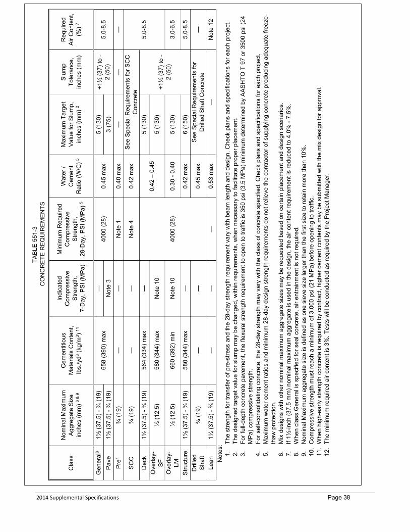
2014 Supplemental Specifications Page 38
TA
BLE
551-
3 C
ON
CR
ETE
REQ
UIR
EMEN
TS
Cla
ss
Nom
inal
Max
imum
Ag
greg
ate
Size
in
ches
(mm
) 6 &
9
Cem
entit
ious
M
ater
ials
Con
tent
, lb
s./y
d3 (kg
/m3 )
11
Indi
cate
d C
ompr
essi
ve
Stre
ngth
, 7-
Day
, PSI
(MPa
)
Min
imum
Req
uire
d C
ompr
essi
ve
Stre
ngth
, 28
-Day
, PSI
(MPa
) 5
Wat
er /
Cem
ent
Rat
io (W
/C) 5
Max
imum
Tar
get
Valu
e fo
r Slu
mp,
in
ches
(mm
) 2
Slum
p To
lera
nce,
in
ches
(mm
)
Req
uire
d Ai
r Con
tent
, (%
) 7
Gen
eral
8 1½
(37.
5) -
¾ (1
9)
658
(390
) max
—
40
00 (2
8)
0.45
max
5
(130
) +1
½ (3
7) to
-2
(50)
5.
0-8.
5 Pa
ve
1½ (3
7.5)
- ¾
(19)
N
ote
3 3
(75)
Pr
e1 ¾
(19)
—
—
N
ote
1 0.
40 m
ax
—
—
—
SCC
¾
(19)
—
—
N
ote
4 0.
42 m
ax
See
Spec
ial R
equi
rem
ents
for S
CC
C
oncr
ete
5.0-
8.5
Dec
k 1½
(37.
5) -
¾ (1
9)
564
(334
) max
—
4000
(28)
0.42
– 0
.45
5 (1
30)
+1½
(37)
to -
2 (5
0)
Ove
rlay-
SF
½ (1
2.5)
58
0 (3
44) m
ax
Not
e 10
5
(130
)
Ove
rlay-
LM
½ (1
2.5)
66
0 (3
92) m
in
Not
e 10
0.
30 -
0.40
5
(130
) 3.
0-6.
5
Stru
ctur
e 1½
(37.
5) -
¾ (1
9)
580
(344
) max
—
0.
42 m
ax
6 (1
50)
5.0-
8.5
Dril
led
Shaf
t ¾
(19)
—
—
0.
45 m
ax
See
Spec
ial R
equi
rem
ents
for
Dril
led
Shaf
t Con
cret
e —
Lean
1½
(37.
5) -
¾ (1
9)
—
—
—
0.53
max
—
N
ote
12
Not
es:
1.Th
e st
reng
th fo
r tra
nsfe
r of p
re-s
tress
and
the
28-d
ay s
treng
th re
quire
men
t var
y w
ith b
eam
leng
th a
nd d
esig
n. C
heck
pla
ns a
nd s
peci
ficat
ions
for e
ach
proj
ect.
2.Th
e de
sign
ed ta
rget
val
ue fo
r slu
mp
may
be
chan
ged,
with
in re
quire
men
ts, w
hen
nece
ssar
y to
faci
litat
e pr
oper
pla
cem
ent.
3.Fo
r ful
l-dep
th c
oncr
ete
pave
men
t, th
e fle
xura
l stre
ngth
requ
irem
ent t
o op
en to
traf
fic is
350
psi
(3.5
MPa
) min
imum
det
erm
ined
by
AASH
TO T
97
or 3
500
psi (
24
MPa
) com
pres
sive
stre
ngth
. 4.
For s
elf-c
onso
lidat
ing
conc
rete
, the
28-
day
stre
ngth
may
var
y w
ith th
e cl
ass
of c
oncr
ete
spec
ified
. Che
ck p
lans
and
spe
cific
atio
ns fo
r eac
h pr
ojec
t. 5.
Max
imum
wat
er c
emen
t rat
ios
and
min
imum
28-
day
desi
gn s
treng
th re
quire
men
ts d
o no
t rel
ieve
the
cont
ract
or o
f sup
plyi
ng c
oncr
ete
prod
ucin
g ad
equa
te fr
eeze
-th
aw p
rote
ctio
n.
6.M
ix d
esig
ns w
ith o
ther
nom
inal
max
imum
agg
rega
te s
izes
may
be
requ
este
d ba
sed
on c
erta
in p
lace
men
t and
des
ign
scen
ario
s.
7.If
1½-in
ch (3
7.5
mm
) nom
inal
max
imum
agg
rega
te is
use
d in
the
desi
gn, t
he a
ir co
nten
t req
uire
men
t is
redu
ced
to 4
.0%
- 7.
5%.
8.W
hen
clas
s G
ener
al is
spe
cifie
d fo
r sea
l con
cret
e, a
ir en
train
men
t is
not r
equi
red.
9.
Nom
inal
Max
imum
agg
rega
te s
ize
is d
efin
ed a
s on
e si
eve
size
larg
er th
an th
e fir
st s
ize
to re
tain
mor
e th
an 1
0%.
10.
Com
pres
sive
stre
ngth
mus
t rea
ch a
min
imum
of 3
,000
psi
(21
MPa
) bef
ore
open
ing
to tr
affic
. 11
.W
hen
high
-ear
ly s
treng
th c
oncr
ete
is re
quire
d by
con
tract
, hig
her c
emen
t con
tent
s m
ay b
e su
bmitt
ed w
ith th
e m
ix d
esig
n fo
r app
rova
l. 12
.Th
e m
inim
um re
quire
d ai
r con
tent
is 3
%. T
ests
will
be c
ondu
cted
as
requ
ired
by th
e Pr
ojec
t Man
ager
.
2014 Supplemental Specifications Page 39
Furnish the names of proposed suppliers and locations of proposed aggregate sources upon notice of award. New sources must be sampled, tested, and approved.
Coordinate with the Project Manager for submitting samples for testing. A. Design. Design the concrete mix as follows:
1. Submit a concrete mix design for each class of concrete to be used on a project. Meet all the requirements of MT 100.
2. Design the concrete mix to meet Table 551-3 requirements or the requirements stated below for specific classes of concrete. State the design proportions in terms of aggregates in a saturated, surface dry condition. Submit the proposed aggregate source and proportion computations. Submit a final mix design for approval at least 15 business days before intended use on form MDT-MAT-008.
3. Furnish materials meeting the requirements of Subsection 551.02. 4. Submit a new design when proposing any change in material sources. 5. The following supplementary cementitious materials (SCMs) may be used as partial replacement for hydraulic
cement in the mix design. a. Fly ash may be included in the mix design for up to 30% by weight of the total cementitious material.
Combinations of various classes of fly ash may not exceed 30% by weight of the total cementitious material. b. Microsilica Fume may be included in the mix design for up to 5% by weight of the total cementitious material
when a minimum of 15% fly ash or GGBFS is also included in the mix design or when the mix design incorporates acceptable blended cement.
c. Metakaolin may be included in the mix design for up to 20% by weight of the total cementitious material. d. Ground granulated blast furnace slag may be included in the mix design for up to 50% by weight of the total
cementitious material. When multiple SCMs are used in a design, the total replacement rate may not exceed 50% by weight of the
total cementitious material. Calculate the W/C ratio as the total weight of water divided by the total weight of cementitious material.
6. Blended cements in accordance with Subsection 551.02 may be used in the mix design. 7. When Type V cement is specified for sulfate resistance, other cementitious material mixtures tested in
accordance with ASTM C1012 may be submitted for approval. Acceptance will be based on expansion less than 0.10% at 18 months.
8. The mix design may include provisions that address special conditions of the project that would otherwise not be allowed. The following provisions may be included in the mix design: a. Delayed Initial Set. The mix may be designed for delayed set time to allow for long haul or other project
conditions. When delayed set is included in the mix design, the time requirements for placing the concrete in final position in accordance with Subsection 551.03.4 may be replaced by time to final placement requirements included in the mix design. Include in the mix design information on the delayed set provisions of the design and specific time to final placement requirements. Support the time to final placement with test results from trial batches.
b. Delayed Strength and Permeability Testing. The mix design may include cementitious materials or other admixtures that result in slow strength gain or permeability reduction. When included in the mix design, testing at 56 days may be requested. Support this request with test results from trial batches. Upon acceptance, 56 day results will be used in all provisions that refer to 28-day strength, and permeability will be accepted in accordance with table 551-8.
B. Class Pave. Design and produce class Pave concrete in accordance with Table 551-3 and include in the mix design flexural strength results of at least 500 psi (3.5 MPa) in accordance with AASHTO T 97.
C. Class Deck and Overlay-SF. Design and produce class Deck and Overlay-SF concrete in accordance with Table 551-3 and the following:
• Use 3%-5% silica fume. Include fly ash and/or GGBFS as SCMs. • SCMs replacement quantities must meet the requirements of Subsection 551.03.2(A)(5). • Do not use incompatible air entraining, water reducing and/or super-plasticizing admixtures. • Mix requires trial batch surface resistivity test results in accordance with AASHTO T 358 greater than 15
kilohm-centimeters at 28 days or 21 kilohm-centimeters at 56 days. Rapid chloride permeability test results in accordance with AASHTO T 277 less than 3300 coulombs at 28 days or 2000 coulombs at 56 days will also be accepted.
• Submit a batching sequence procedure with the mix design including the amount of material charged and the time before the next material will be added. Include approximate mixer revolutions for each stage of the sequence.
• The target strength to be used for incentive calculations is the 28/56-day strength submitted with the mix design. If the mix design strength is greater than 5500psi, the target will equal 5500psi.
2014 Supplemental Specifications Page 40
• When barrier rail is cast with Class Deck concrete, the lower range for the W/C ratio may be reduced to 0.38. Submit the request for approval with the mix design.
• Alternative mix designs not in accordance with Table 551-3 may be accepted provided the following
requirements are met: 1. Include in the design compressive strength test results according to AASHTO T 22 for 3, 7, and 28 days. The
design must produce strengths in accordance with Table 551-3 by the specified age. 2. Include in the mix design shrinkage test results according to AASHTO T 160. The maximum allowed shrinkage
for mix design acceptance is .0300% at 28 days. 3. Include in the mix surface resistivity test results in accordance with AASHTO T 358 greater than 15 kilohm-
centimeters at 28 days. 4. Include in the mix design creep test results at 28 days according to ASTM C512. 5. Include in the mix design modulus of elasticity (MOE) results according to ASTM C469. 6. Include in the mix design air-void spacing results according to ASTM C457 modified point-count method at 100x
magnification. The average of all tests must not exceed 0.009 inches (0.230 mm) with no single test greater than 0.010 inches (0.260 mm). The total air content must exceed 5.5%.
7. Design and produce concrete maintaining a plastic air content of 5.5% - 8.5%. 8. Submit a batching sequence procedure with the mix design including the amount of material charged and the
time before the next material will be added. Include approximate mixer revolutions for each stage of the sequence.
9. The target strength to be used for incentive calculations is the 28/56-day strength submitted with the mix design. If the mix design strength is greater than 5500psi, the target will equal 5500psi.
D. Class Drilled Shaft. Drilled shaft concrete is a highly workable concrete that can flow through dense reinforcement and adequately fill voids without segregation or excessive bleeding without the need for vibration. Drilled shaft concrete should not begin initial set until the placement is complete. Design and produce Class Drilled Shaft concrete in accordance with Table 551-3 and the following: 1. Set a target slump that meets the needs of the project. Set the target slump no lower than 8 inches (200 mm). Do
not place drilled shaft concrete having a slump of less than 7 inches (175 mm). 2. Include with the mix design an estimate of the maximum time from producing the 1st batch of concrete for a shaft
to the anticipated completion of that shaft. All concrete used for the drilled shaft must maintain a minimum of a 6-inch (150 mm) slump until 2 hours after the estimated completion.
3. Air entrainment may be used in drilled shaft concrete if needed to reduce bleed water or achieve certain placement properties
4. Self-consolidating concrete may be used for drilled shaft mix designs. When used, meet the above requirements and those of Subsection 551.03.2(F).
E. Latex-Modified Overlay Concrete (Overlay-LM). Design and produce overlay-LM concrete in accordance with the following requirements: 1. Use only Type I or Type II hydraulic cement. 2. Furnish concrete with a latex emulsion admixture rate of 25 gallons per cubic yard (123.8 L/m3). Use a latex
admixture containing a polymer of 66% ± 5% styrene and 34% ± 5% butadiene, with the polymer comprising between 46% and 49% of the total emulsion. The emulsion must have a sodium alkyl sulfate stabilizer acting as an anionic surfactant, polymer average particle size between 1,900 and 2,500 angstroms, a weight of 8.43 to 8.52 pounds per gallon (1.01 - 1.02 kg/L) at 75 °F (24 °C), and a pH between 9.5 and 11.0.
3. Protect the latex admixture from temperatures below 32 °F (0 °C) and above 85 °F (29 °C) at all times. Provide a thermometer capable of storing minimum and maximum temperatures and place it with any admixture stored on site. Replace admixture subjected to temperatures outside the range above at no expense to the Department.
F. Controlled Low Strength Material (CLSM). CLSM is a mixture of hydraulic cement, SCMs, aggregate, natural sands, silty sands, air entraining admixture and water. CLSM contains a low cementitious content for reduced strength development. Submit a mix design for approval including aggregate gradations, cement and SCM mill certifications, proportioning, and trial batch information. 1. Excavatable. Design and produce excavatable CLSM in accordance with the following requirements:
a. Unconfined compressive strength between 35 psi and 150 psi (0.24 - 1 MPa) determined by ASTM D4832. b. Air content between 5% and 40% determined by ASTM D6023. c. Unit weight of 80 – 110 lbs/ft3 (1,280 – 1,760 kg/m3) determined by ASTM D6023. d. Consistent flow producing a self-leveling product free of segregation determined by ASTM D6103 e. Do not use coarse aggregate in excavatable CLSM. (Maximum ⅜-inch (9.5 mm) nominal maximum
aggregate size designs.) 2. Non-Excavatable. Design and produce non-excavatable CLSM in accordance with the following requirements:
a. Unconfined compressive strength greater than 150 psi (1 MPa) determined by ASTM D4832
2014 Supplemental Specifications Page 41
b. Air content between 5% and 30% determined by ASTM D6023. c. Unit weight of 100-130 lbs/ft3 (1,600 – 2,080 kg/m3) determined by ASTM D6023. d. Consistent flow producing a self-leveling product free of segregation determined by ASTM D6103. Do not use materials in CLSM with a plasticity index over 4 according to AASHTO T 89 and AASHTO T90. Furnish aggregates in accordance with Table 551-4 or Table 701-2.
TABLE 551-4 CLSM GRADATIONS
Percentage By Weight Passing Square Mesh Sieves Sieve Size Percent Passing
¾-inch (19 mm) 100 No. 4 (4.75 mm) 65 - 100 No. 30 (0.600 mm) 40 - 80 No. 200 (0.075 mm) 0 - 30
High air generators or foaming agents may be used in lieu of conventional air entraining admixtures and may be added at the jobsite and mixed in accordance with the manufacturer’s recommendation. The requirements for percent air and unit weight are for laboratory mix designs only and are not intended for jobsite acceptance requirements.
Produce a consistent mix that results in a flowable product at the time of placement which does not require manual means to move it into place.
Secure tanks, pipes and other members to be encased in CLSM to prevent displacement during placement. Protect CLSM from traffic until sufficient strength has been achieved for further construction operations. The CLSM may be mixed onsite, or at a ready-mix plant and transported to the site. Keep the mix homogeneous
and in a suspended condition to prevent settling of the materials prior to placement. Characteristics of CLSM include, consistency, workability, and plasticity such that the material is flowable, self-compacting and self-consolidating during placement.
G. Self- Consolidating Concrete (SCC). SCC is a highly workable concrete that can flow through densely reinforced or complex structural elements under its own weight and adequately fill voids without segregation or excessive bleeding without the need for vibration.
SCC may be used for Classes General (in precast or aesthetic placements only), Structure, and Drilled Shaft concrete. Design and produce SCC in accordance with Table 551-3 and the following: 1. 28 day compressive strength meeting the requirements of the class of concrete specified or established in the
contract (e.g. Class Drilled Shaft = 4000 psi (28 MPa)). Many precast designs requiring Class General concrete have varying design strengths.
2. Provide a slump-flow within ± 2 inches (± 50 mm) of the target value. Set target within the range of 20 to 26 inches (450 to 710 mm). Test in accordance with AASHTO T 347. When used for a drilled shaft design, include in the design, hourly slump-flow retention testing up to the desired placement time of the shaft.
3. Provide a maximum visual stability index (VSI) of 1 in accordance with AASHTO T 351. 4. Provide a maximum J-ring value of 2 inches (50 mm) in accordance with AASHTO T 345. When used for a
drilled shaft, include in the design, hourly J-ring testing up to the desired placement time of the shaft. Include the above test results in the mix design submittal. If SCC is used in the production of precast items,
meet the testing requirements in Subsection 554.03.6. H. Class Structure Concrete. Design and produce Class Structure concrete in accordance with Table 551-3.
Alternative mix designs not in accordance with Table 551-3 may be accepted provided the following requirements are met. 1. Include in the design compressive strength test results according to AASHTO T 22 for 3, 7, and 28 days. The 28-
day results must exceed specified strength. 2. Include in the mix design shrinkage test results according to AASHTO T 160. The maximum allowed shrinkage
for mix design acceptance is .0350% at 28 days. 3. Include in the mix design creep test results at 28 days according to ASTM C512. 4. Include in the mix design MOE results according to ASTM C469. 5. Include in the mix design air-void spacing results according to ASTM C457 modified point-count method at 100x
magnification. The average of all tests must not exceed 0.009-inch (230 μm) with no single test greater than 0.010-inch (260 μm). The total air content must exceed 5.5%.
6. Design and produce concrete maintaining a plastic air content of 5.5% - 8.5%. I. Class Pre Concrete. Design and produce Class Pre concrete in accordance with Table 551-3. Alternative mix designs
not in accordance with Table 551-3 may be accepted provided the following requirements are met. 1. Include in the design compressive strength test results according to AASHTO T 22 for 3, 7, and 28 days. Also
include strength tests at intended de-tensioning/release times (e.g. 12 hrs, 16 hrs, 24 hrs, etc.) The 28-day results must exceed specified strength.

2014 Supplemental Specifications Page 42
2. Include in the mix design shrinkage test results according to AASHTO T 160. 3. Include in the mix design creep test results at 28 days according to ASTM C512. 4. Include in the mix design MOE results according to ASTM C469.
J. Prepackaged Concrete. Prepackaged concrete or rapid set patching material must contain a product data sheet proving the product meets the specifications required for its intended use. Prepackaged concrete is subject to Project Manager approval.
K. Lean Concrete. Design and produce Class Lean concrete in accordance with Table 551-3. Submit material proportioning to the Project Manager for acceptance. A mix design in accordance with MT 100 is not required for Class Lean concrete.
551.03.3 Batching, Mixing, Handling and Sampling Produce each class of specified concrete from approved material batched in the proportions specified in the approved mix
design. Correct for moisture content variations. All concrete aggregates are sampled using methods described in MT 201 using
sample sizes used in MT 202. MT 122 will be used to calculate combined gradations. The water may be proportioned by weight or volume. Proportion the cement and aggregates by weight. The temperature of the combined material must be less than 130 °F (54 °C) before the addition of cementitious materials. Meet the requirements of ASTM C94 for all concrete batch plants and operations prior to and throughout production of
concrete for any work, including concrete for any field trial batches. In addition to ASTM C94, meet the following requirements throughout the production of concrete:
A. Quality Control. When requested, furnish documentation for all the plant’s equipment including each plants quality control procedures, calibration records, maintenance records, and any other information pertinent to proper concrete production. All measuring devices, batching equipment, trucks, and mixers are subject to approval.
B. Water. 1. Weigh Measurement. Ensure the weigh equipment measurements are not effected by pressure variations in the
water supply lines. The Project Manager may require an auxiliary tank for filling the weighing tank. 2. Metering. Measure water volume by metering through a recording water-meter device, accurate to within plus or
minus 1.0% of the required volume or plus or minus 1 gallon (3.8 L), whichever is less. Completely discharge wash water from the mixer before starting any batching operation.
C. Cementitious Materials. 1. Proportion cementitious materials by weight on all projects for all classes of concrete. 2. Ensure equipment for weighing cementitious material is accurate to within 0.5% of the true weight. 3. Weigh cementitious material to within 1.0% of the batch target weight. 4. Weigh each cementitious material separately.
D. Admixtures. If using 2 or more admixtures in a single concrete batch, add each admixture separately to prevent interaction of the different admixtures before mixing with other batch materials. Agitate admixtures to ensure homogeneous concentrations in accordance with the manufacturer’s recommendations.
If using a mechanical dispenser for proportioning admixtures, provide a site gauge or meter. Ensure unobstructed flow and accurate dosing of admixtures.
Batch admixtures in accordance with ASTM C94. E. Aggregate. Proportion aggregate by weight on all projects for all classes of concrete.
Ensure equipment for weighing aggregates is accurate to within 0.5% of the true weight. Weigh each aggregates to within 2% of the batch target weight. Weigh each size of aggregate separately.
F. Batch Ticket. Furnish the Project Manager a printed record of each batch in accordance with ASTM C94. Include on the ticket any water or admixture added after the record is printed and the initials of the person making the additions. Approval is required before any addition to the mix after batching and initial mixing has been completed.
G. Mixers. Use mixers that combine cementitious materials, aggregates, water, and admixtures within the specified time to form a uniformly mixed mass.
Meet the requirements of ASTM C94. Operate mixers following the manufacturer’s recommendations. The Department may require uniformity testing. When required, meet the requirements of Subsection 106.04. Do not place concrete improperly or inadequately mixed in the work. If incorporated, remove the concrete at no
cost to the Department. Do not mix, transport, or place concrete using equipment with aluminum or aluminum parts that contact the
concrete. Produce concrete in such quantity and at such a rate as proper placement and finishing will permit. Do not re-
temper partially set concrete. Do not use mixed concrete that has remained in the truck mixer drum longer than 10 minutes without agitation.

2014 Supplemental Specifications Page 43
When silica fume is incorporated in the mix design, the maximum mixer revolutions will be waived. Ensure a minimum of 50 revolutions at mixing speed when the concrete is in a low-slump stage [2 to 3 inches (50 to 75 mm)] to properly disperse silica fume particles.
H. Job-Site Additions. On-site addition of air entraining or high range water reducing admixtures is permitted up to 2 times. Do not re-dose with other admixtures without the approval of the Project Manager. On-site dosing of water or admixture in no way relieves the contractor of producing passing plastic and hardened concrete test results. 1. Water. Do not exceed the approved W/C ratio.
The addition of water is allowed only 1 time and a minimum of 30 revolutions at mixing speed are required before discharge of concrete. Do not add water if part of the batch has been discharged as a W/C ratio cannot be determined.
Do not add water if the slump is within specified range. 2. Admixture. Do not exceed manufacturer’s recommended dosage rates unless otherwise approved in the mix
design stage. Only admixtures included in the approved mix design may be dosed on-site. A minimum of 30 revolutions at
mixing speed are required before discharge of concrete. Do not add admixtures if any concrete has been discharged from the mixer other than the minimal amount
for initial testing. When the measured plastic air content or slump exceeds the upper test limit and there is time available within
the discharge time limit specified, rotate the load at agitation speed and re-test the air content and/or slump. Do not use additives to reduce the air content and/or slump.
No other materials may be added to the concrete mixture.
551.03.4 Transporting Concrete Ensure that the capacity of the plant and transportation equipment provides a delivery rate to permit handling, placing,
and finishing of the work. Time the delivery of loads to prevent the in-place concrete from taking initial set before succeeding layers or lifts are
placed. Do not permit any layer or lift of concrete to remain exposed in excess of 20 minutes before being covered by fresh concrete.
Document the method and time of delivery by batch tickets issued to the driver and signed by the Inspector at the plant if present. Deliver the ticket to the Inspector upon arriving at the project.
Meet the requirements of ASTM C94 and the following: A. Revolving Drum Mixers. Discharge the concrete at the job and place it in final position within 1½ hours after
introducing the mixing water and cement. If long hauls or other project conditions are expected, meet the requirements of Subsection 551.03.2(A)(8)(a).
When the ambient temperature is 85 °F (29 °C) or above, place the concrete in final position within 1 hour after the water and cement are introduced.
B. Non-agitating Transportation Equipment. Do not use non-agitating transport equipment to transport concrete except when placing concrete pavement in accordance with Section 501.
551.03.5 Placing Concrete Place concrete in accordance with Sections 501, 552, and 553. Place Class Deck concrete, and Class Structure concrete if used within bridge decks, with a temperature between 50 and
80 °F (10 and 26 °C). Place all other classes of concrete with a temperature between 50 and 85 °F (10 and 29 °C). Always place concrete as near as possible to its final position. Do not place concrete that has taken initial set. Do not place concrete: 1. On frozen or ice-coated ground or subgrade; 2. Against or on ice-coated forms, reinforcing steel, structural steel, conduits, precast members, or construction joints; 3. Under rainy conditions; stop the placement of concrete before the quantity of surface water is sufficient to effect or
damage surface mortar quality, cause a flow, or wash the concrete surface; 4. In any foundation until the Project Manager has approved its depth and character; 5. In any form until the Project Manager has approved it and the placement of any reinforcing in it; or 6. In any work area when vibrations from nearby work may harm the concrete’s initial set or strength. Ensure all reinforcement and other embedded items are clean and free from dried mortar, rust, scale, oil, or foreign matter
before placing concrete. Remove all sawdust, chips, other construction debris and extraneous matter from the interior of forms before placing
concrete. Treat the forms interior surfaces to prevent mortar adhesion. Moisten all foundations, forms, and contacting concrete surfaces with water just before the concrete is placed. Remove
any standing water on surfaces which will contact with the concrete.
2014 Supplemental Specifications Page 44
Provide a method of concrete placement that has a consistent, minimal impact on the concrete properties. All equipment proposed for use in mixing, conveying, placing and compacting the concrete is subject to Project Manager approval prior to its use. All the necessary equipment for any particular placement must be on site and proven to be in working condition before the placement commences. Ensure the equipment is well maintained, suitable in kind and adequate in capacity for the work.
Support bars to maintain their position as shown in the contract. Place and secure all reinforcing, dowels, and other embedded items as specified. Deposit concrete in small quantities at many points and then work or run it along the forms. Carefully fill each part of the
forms, depositing the concrete as close as possible to its final position, working the coarse aggregates back from the face and forcing the concrete under and around the reinforcing bars.
Deposit concrete around steel shapes and closely spaced reinforcing bars, on 1 side of the steel, uniformly working it until the concrete flushes under the steel to the opposite side before any concrete is placed on the opposite side or over the steel.
Place concrete with means as to avoid segregation of the materials and the displacement of the reinforcement. Remove and discard any concrete that is segregated, is too wet for use, or is not of uniform consistency. Deposit concrete through an approved means when placement operations involve a free drop of concrete by more than 5 feet (1.5 m) to prevent segregation.
Place concrete in a continuous operation between expansion or construction joints. Thoroughly clean all chutes, troughs, and pipes after each run. Discharge any flushing water away from the forms and in place concrete. Once the concrete has taken initial set, avoid jarring the forms or straining the projecting reinforcement ends. A. Placement Methods. All placement methods are subject to approval.
1. Truck Chute. Use metal or metal-lined troughs and chutes that extend to the point of deposit. Regulate the discharge.
2. Pumping Concrete. When concrete pumps are used for placement, prior to use on the first placement of each day, visually inspect the pumps water chamber for water leakage. Do not use a pump that allows free water to flow past the piston.
If a concrete pump is used as the placing system, discard the pump priming slurry before placement. Eliminating the priming slurry from the concrete may require that several cubic yards of concrete are discharged through the pumping system and discarded.
Use of a concrete pump requires a written plan to place the remaining concrete if the pump breaks down. Provide a pump that produces a continuous flow of concrete without air pockets. Arrange equipment so that
the impact on the plastic air content of the concrete is affected as little as possible, and that the freshly placed concrete is not damaged by any form of vibration. If boom angles will vary significantly, furnish means to control air content variation.
3. Conveying Concrete. When a conveyor is used for placement, prior to use on the 1st placement of each day, visually inspect the conveyor to ensure proper operation. Provide a belt free of tears and holes and operates smooth and free of bouncing and jarring to prevent segregation of the concrete. Protect the concrete while on the conveyor to prevent the concrete’s plastic properties from changing.
Do not use a conveyor exceeding 200 feet (60 m). Equip all conveyors with a drop-chute and scraper to prevent segregation and mortar loss respectively. Once concrete placement begins, ensure that there is proper and equal edge-distance between the edge of
the belt and windrow of concrete. 4. Bucketing Concrete. When a bucket is used for concrete placement, prior to use on the first placement of each
day, visually inspect the bucket for proper working condition and contaminants. The bucket should be clean and free of hardened concrete and excess of release agent.
Once concrete has been discharged into the bucket, do not place concrete back into a mixer to be altered or remixed.
B. Consolidation. Thoroughly consolidate concrete, except SCC, during and immediately after depositing into the work. Consolidate the concrete by mechanical vibration subject to the following: 1. Apply the vibration internally unless otherwise approved or as provided herein. 2. Vibrate the concrete at a minimum 4,500 impulses per minute or as recommended by the vibrator manufacturer. 3. The vibration must visibly affect the concrete mass, producing a 1-inch (25 mm) slump over a minimum 18-inch
(455 mm) radius. 4. Use enough vibrators to consolidate each batch immediately after it’s placed. 5. Vibrate the concrete around the reinforcement and imbedded fixtures and into the form corners and angles. 6. Vibrate at the point of deposit in areas of freshly deposited concrete. Slowly insert and remove the vibrators from
the concrete. Vibrate to thoroughly consolidate the concrete without causing segregation or forming localized grout areas.
7. Vibrate at uniformly spaced points and no farther apart than twice the radius over which the vibration is visible.

2014 Supplemental Specifications Page 45
8. Do not apply vibration directly to or through the reinforcement or to non-plastic sections or layers of concrete. Do not use vibrators to transport concrete in the forms. Use plastic or rubber tipped vibrator heads when placing concrete near epoxy coated reinforcing steel.
9. Supplement vibration by spading and tamping to produce smooth surfaces and dense concrete along form surfaces, in corners and locations impractical to reach with the vibrators.
Refer to Section 501 for consolidation requirements for concrete paving.
551.03.6 Weather and Temperature Limitations Concreting during hot or cold weather requires an approved written plan to be implemented upon abrupt changes in
weather conditions or equipment failures. When required, use Omega HH309A four channel data logging thermometers. A. Hot Weather Concreting. Defined as job-site conditions that accelerate the rate of moisture loss or rate of cement
hydration of freshly mixed concrete. Do not place Classes Deck or Overlay concrete in temperatures exceeding 95 °F (35 °C). Other classes of concrete may be placed in temperatures exceeding 95 °F (35 °C) with Project Manager approval.
When hot weather concreting is anticipated, submit a hot weather concreting plan for review and approval. Include detailed procedures, including production, placement, finishing, curing and protection of concrete during hot weather concreting.
Do not place concrete when the ambient temperature is 85 °F (29 °C) and rising and/or the evaporation rate is greater than 0.2 lb/ft2/hr. (1 kg/m2/h) without an approved hot weather concreting plan. Do not place Classes Deck or Overlay without an approved plan when the ambient temperature is greater than 80 °F (27 °C) and/or when the evaporation rate is greater than 0.15 lb/ft2/hr. (0.75 kg/m2/h).
When hot weather as defined above exists, monitor site conditions (air temperature, humidity, wind speed) to assess the need for evaporation control measures beginning no later than 1 hour before the start of concrete placing operations. Continue to monitor site conditions at intervals of 30 minutes or less until specified curing procedures have been applied. 1. Materials. Produce concrete at a temperature such that its maximum temperature at discharge will not exceed
the specified maximum allowable concrete temperature. Acceptable production methods to reduce the temperature of the concrete include: shading aggregate stockpiles, sprinkling water on coarse aggregate stockpiles; using chilled water for concrete production; substituting chipped or shaved iced for portions of the mixing water; and cooling concrete materials using liquid nitrogen.
Include in the submittals for hot weather concreting which methods will be used and in what order they will be initiated when multiple methods are to be used. The substitution of other cooling methods will be considered by the Department when requested in the submittal and accompanied by satisfactory supporting data.
2. Construction. Include in the plan methods that will be used to maintain surfaces that will come in contact with the plastic concrete below 85 °F (29 °C). Include methods and equipment that will be used to keep the plastic concrete from cracking (e.g. fogging equipment, burlap, plastic, curing compounds, etc.). Describe devices or procedures that will be used to monitor wind speed, temperature, humidity, and other weather variables determining evaporation rate. Also include a detailed description of curing practices that will be used to supplement standard requirements in hot weather placements. Protect the concrete against thermal shrinkage cracking due to rapid drops in concrete temperature greater than
40 °F (22 °C) during the first 48 hours unless otherwise specified. Under hot weather conditions, scheduling placements at other-than-normal hours may be advisable. Concrete
showing evidence of plastic shrinkage cracking or thermal cracking will be removed and replaced at no cost to the Department.
B. Cold Weather Concreting. Defined as when the weather forecast predicts air temperatures below 35 °F (2 °C) at any time during the specified curing and protection period following concrete placement. Assume all risk for placing concrete during cold weather. Replace frozen or damaged concrete at Contractor expense.
Remove ice, snow, and frost from the forms, subgrade, adjacent concrete, and reinforcing bars before placing concrete. Do not place concrete on frozen base or subgrade.
When cold weather concreting is anticipated, submit a cold weather concreting plan for review and approval. Include detailed procedures for production, transportation, placement, curing, and temperature monitoring of the concrete during cold weather. Submit the plan a minimum of 15 calendar days prior to any concrete which is scheduled to be placed during cold weather. Prepare and submit a separate cold weather concreting plan for each concrete component which requires different methods of protection from cold weather. Clearly indicate which concrete components are covered by each submittal. 1. Cold Weather Plan. Include, as a minimum, the following items in the cold weather concreting plans:
a. Materials, details, and locations for insulating blankets, enclosures, or other methods to be used to protect concrete from cold weather.

2014 Supplemental Specifications Page 46
b. Method for verifying the minimum concrete compressive strength has been reached to allow formwork and cold weather protection removal. Indicate whether cylinder testing or maturity method will be used. If using the maturity method, submit a plan meeting ASTM C1074 requirements.
c. Recording thermometer information and location. Include proposed number and location of thermometers in the concrete.
d. Heating equipment and locations, if used. Provide product information on heating equipment and equipment placement.
2. Fresh Concrete Temperatures. Place fresh concrete with a temperature between 50 and 85 °F (15 and 32 °C). Eliminate frozen lumps, ice, and snow before aggregates are used in production. The Contractor may warm stockpiled aggregates with dry heat or steam, but not by applying flame directly or
under sheet metal. If the aggregates are in bins, steam or water coils or other heating methods may be used if aggregate quality is not affected. Live steam heating is not permitted on or through aggregates in bins. If using dry heat, increase mixing times enough to permit the dry aggregates to absorb moisture.
Use equipment and methods that heat the materials evenly. Do not add chlorides, chemical admixtures, or other ingredients to the concrete to prevent freezing.
3. Protection of Concrete. Enclose the structure in such a way that the concrete and air within the enclosure can be kept above 60 °F (15 °C) for a period of 7 calendar days or the specified curing period after placing the concrete. Ensure that the relative humidity remains above 80% within the enclosure.
Before placing concrete, provide adequate preheat to raise the temperature of the formwork, reinforcing steel, adjacent concrete, and subgrade to at least 35 °F (2 °C).
Furnish and place enough temperature probes within the concrete to ensure the temperature of the concrete is adequately monitored. Install a minimum of 3 temperature probes within each concrete element. Ensure that the temperature probes cannot be dislodged by the placement of concrete, vibration, or workers. Include at least 1 additional temperature probe to record ambient outside air temperature. Where heated enclosures are used, include a temperature recording device inside the heated enclosure. Temperature probe locations are subject to approval. Provide access for Department personnel to each probe for downloading recorded data.
4. End of Curing Period. The conclusion of the curing period is defined when field cured cylinders meet design strength, maturity meter readings are satisfactory, or the specified curing days are reached and all temperature recording data has been submitted. a. Field Cured Specimens. Mold a minimum of 6 field cured cylinders per lot. Cast field-cured cylinders in
accordance with MT 101. Place the cylinders at locations designated by the Project Manager and expose them to the same conditions as the concrete being placed until they are removed for testing.
Test field-cured cylinders within 24 hours after removal from cold weather protection according to AASHTO T 22, except that the moist cure period is omitted. Perform tests using a certified testing laboratory. Furnish the Project Manager certified copies of the test results.
Cast enough cylinders to guarantee the required strength has been met for protection removal. The Department reserves the right to witness selected tests and testing procedures. Two cylinders constitute a test with the test value being the average of the 2 compressive strengths.
The average of all sets must meet the specified strength. Continue curing and protection until the tests indicate the specified compressive strength is reached.
b. Removing Protection. When the curing period has ended and the design strength is met, withdraw protection and heating in such a manner so as not to induce thermal shock stresses in the concrete.
Gradually reduce the temperature of the concrete at a rate not exceeding 15 °F (9 °C) per hour. Do not exceed a temperature differential of 40 °F (4 °C) between the core of the element and the surface of the element. In addition, the temperature differential between the surface of the element and the ambient air shall not exceed 15 °F (9 °C). Ambient air temperature is defined as the temperature at mid-height of the element and 12 inches (305 mm) from the surface of the element.
All concrete must achieve a minimum of 4000 psi (28 MPa) before being exposed to freeze/thaw cycles. The Contractor is solely responsible for protecting concrete from inclement weather during the entire curing
period. Permission given by the Project Manager to place concrete during cold weather in no way ensures acceptance of the work by the Department. Should the concrete placed under such conditions prove unsatisfactory in any way, the Project Manager has the right to reject the work although the plan and the work were carried out with the Project Manager’s permission.
551.03.7 Curing Concrete Continuously water cure any class of concrete used for bridge deck construction for 14 calendar days as specified below. Continuously water cure class Overlay-SF for 7 calendar days as specified below. Continuously water cure class Overlay-LM for 72 hours as specified below, followed by a dry cure. Begin the dry cure at
the end of the 72-hour wet cure period by removing the burlap and the polyethylene. Allow the concrete to undergo 48 hours of dry cure. Keep the bridge closed to traffic an additional 48 hours if the air temperature falls below 50 °F (10 °C) during the

2014 Supplemental Specifications Page 47
cure. Allow no traffic on the overlay surface until the end of the dry cure and the transverse deck grooving has been completed.
Continuously cure all other concrete surfaces for 7 calendar days by either water curing or liquid membrane-forming curing compound as specified below. Design strength must be verified by field-cured cylinders in accordance with AASHTO T 22.
Do not place curing compounds on concrete that is still bleeding. Protect freshly placed concrete from freezing, high temperatures, large temperature differentials, premature drying,
excessive moisture, and moisture loss for the period of time necessary to develop the desired concrete properties. Protect exposed concrete surfaces from premature drying by covering with canvas, plastic sheets with sealed joints,
burlap, or other approved materials. Keep the concrete moist. Continually moisten uncovered surfaces by fogging. Do not allow water to drip, flow, or puddle on the concrete surface during fog misting, when placing the burlap, or at any time before the concrete has achieved final set. Do not use intermediate monomolecular film curing agents (evaporation retarders) as a method to reduce moisture loss.
The concrete surfaces against forms may be cured by leaving the forms in place for at least 7 calendar days. Keep the concrete surfaces moist after removing forms until surface repair is completed and one of the final cure methods
described below is used. Surface repair includes removal of irregularities and repair of all depressions, voids, and air holes. After placement, cure concrete surfaces as follows: A. Water Cure. Keep all finished top surface concrete moist with a fine water mist until the burlap is placed.
Place wet burlap in accordance with Subsection 717.01.2 immediately behind concreting operations no later than 15 minutes after finishing. Do not use products having a laminated moisture barrier. Soak burlap for a minimum of 24 hours before use. Keep the burlap wet until concrete reaches sufficient strength to place soaker hoses or other effective means of providing moisture without marring the surface. Once a watering system is placed, place an approved reflective type sheeting or blanket over the watering system in accordance with Subsection 717.01.1 and cover to reduce evaporation. The entire concrete surface must remain moist throughout the full cure period. Ensure the temperature of all water used in the water cure is within 20 °F (11 °C) of the in-place concrete temperature. Secure covers and sheeting to prevent them from being lifted or displaced.
B. Liquid Membrane-Forming Curing Compound. Furnish and uniformly apply a liquid membrane-forming curing compound in accordance with Subsection 717.01.3 or 717.01.4 over exposed surfaces.
Deliver membrane-curing compound to the job in the manufacturer’s original container, clearly labeled with the manufacturer’s name and contents.
The compound must be ready to use as shipped by the manufacturer. Do not dilute the compound. Do not use curing compound without providing the Project Manager a manufacturer’s product data sheet. Use white-pigmented compound for pavements. Use products in accordance with 717.01.4 on curbs, sidewalks, median caps, and barrier rail. Use a product in
accordance with 717.01.3 on substructure components, superstructure components other than those requiring a water cure, and all other exposed concrete surfaces. Ensure products furnished in accordance with Subsection 717.01.3 are clear and contain a fugitive dye that makes the film visible on the concrete for at least 4 hours after application but does not affect the concrete surfaces natural color after curing.
Thoroughly mix and apply the compound following the manufacturer’s instructions or apply at a rate exceeding 1 gallon per 150 square feet (0.27 L/m2) and ensure complete coverage with no transparent areas showing obvious color differential.
Apply the curing compound immediately after the finishing operation using a mechanical pressure distribution system to provide uniform coverage. During windy conditions, equip the spray nozzles with hoods.
When concrete is placed in forms, immediately apply the curing compound after form removal if the concrete has not reached its design strength.
A hand-operated sprayer providing uniform coverage may be used to apply liquid curing compound to areas where a mechanical sprayer is impractical.
If the curing membrane is damaged from any cause during the curing period, re-coat the damaged areas immediately.
Do not apply membrane-curing compound to construction joint surfaces. Protect exposed steel during application of curing compounds.
C. Steam-Cure for Precast Concrete Items. Completely enclose or cover the casting beds for steam-cured members using curing blankets or other approved flexible coverings. Provide a minimum 6 inches (150 mm) of free air space between the enclosure or coverings and all concrete surfaces.
Secure flexible coverings to prevent moisture loss. Provide moisture before the cure cycle to aid hydration and prevent surface cracks caused by rapid water loss from the concrete.
Steam may be introduced before starting the cure cycle if the enclosure temperatures are maintained between 50 and 70 °F (10 and 21 °C). Fog-spray or cover the top surfaces of the members with wet blankets within 15 minutes after placing concrete to prevent moisture loss for a 3 hour period before the cure cycle.
2014 Supplemental Specifications Page 48
Begin the steam-cure cycle after the concrete has been in place at least 3 hours. Maintain steam at 100% relative humidity, applied so it does not damage the surface of the concrete, forms, or tendons.
Raise the ambient temperature within the enclosures no faster than 40 °F (22 °C) per hour to a maximum temperature between 120 and 160 °F (49 and 71 °C). Maintain the temperature until the concrete has reached strength for transfer of prestress or design strength.
Once the cure cycle is complete, cool the precast items by decreasing the temperature within the enclosures no faster than 40 °F (22 °C) per hour until the temperature difference between the inside and outside air is within 25 °F (14 °C), unless otherwise approved.
Keep a curing time-temperature record for each concrete placement within the casting bed. Provide 1 automatic temperature-recording thermometer for each 200 feet (61 m), or fraction thereof, of continuous bed length used. Record curing temperatures continuously for the full curing cycle. Place the temperature sensors at approved locations. Supplement automatic recording thermometers with standard bulb-type thermometers placed at approved locations. Certify the accuracy of automatic recorders once each year or when the recorder accuracy is in question. Steam curing is not permitted without automatic recorders.
The sideforms may be removed at the Contractor’s discretion. Assume all responsibility removing forms before breaking the release cylinders. Concrete members damaged from early form removal will be rejected.
The cure cycle may be interrupted a maximum 20 minutes for form removal. Do not expose the members to below-freezing temperatures within 6 calendar days of casting. In place of the 6-
day requirement, the cure time may be based on the concrete strength. The concrete strength is determined by the average strengths of 3 standard 6 x 12-inch (152 x 305 mm) or 4 x 8-inch (102 x 203 mm) cylinders cast from different batches of concrete used in each casting. Expose these cylinders to the same cure and temperature conditions as the precast items. Immediately test the cylinders according to AASHTO T 22 without further curing, once they are removed from the cure area.
Curing may be discontinued if the average strengths of the 3 cylinders equals or exceeds specified strengths. Protect the member from freezing temperatures for the 6-day period if the average compressive strength fails to meet specified strength. Cool all members as specified in this Subsection.
Cast compression cylinders for field tests of the 28-day strengths following MT 101. Cast the number of test cylinders as required in Subsection 551.03.8(C) and MT 111.
The Contractor may submit in writing, alternate curing methods, for approval.
551.03.8 Testing and Acceptance of Concrete Construct any products that are not cast-in-place, and not produced at a PCI, ACPA or NPCA certified precast plant, in
accordance with Subsection 605.03. These products will be evaluated in accordance with Subsection 551.03.8(C) for the class of concrete specified.
A. Pre-testing of Concrete (Classes Structure, Deck and Overlay). Pre-testing is not required for concrete placements smaller than 7 cubic yards (m3). The Department will perform pre-tests for air content and slump at the start of each concrete production run and any time there is a significant change in the pumping configuration or concrete placement as determined by the Project Manager. Meet the following requirements: 1. Discharge and waste a minimum of 0.25 cubic yards (0.2 cubic meters) of concrete. 2. Collect a sample. 3. If slump and air content pre-tests indicate the sampled concrete meets applicable specifications, placement may
begin. 4. If a pre-test produces a failing result, the truck may be dosed with approved admixtures included in the mix
design, in accordance with Subsection 551.03.3(H). 5. If after all additions in accordance with Subsection 551.03.3(H) are made and a second pretest again produces a
failing result, the truck will be rejected. The testing process will be repeated on subsequent trucks until passing air and slump results are achieved. Pre-test results are not used for concrete lot acceptance.
B. Sampling and Testing. Furnish an adequate and representative sample of concrete in accordance with AASHTO R 60 from the point of placement to an area designated by the Project Manager for testing of concrete properties and molding of test specimens. Do not drop or agitate samples. The sampling and transport must be witnessed by the Department. The Department will take possession of the sample and begin the following applicable tests. 1. Compressive Strength Testing. Furnish samples for determining compressive strength following AASHTO R 60.
Test cylinders will be cast and cured following MT 101 and tested in accordance with AASHTO T 22 at a frequency determined by MT 601. Test cylinders for SCC will be cast and cured in accordance with MT 117. Compressive strength tests may be molded at any time if inconsistency between batches is identified or suspected. A compressive strength set consists of 4 test cylinders made at the same time from the same batch of concrete. Tests for plastic properties will also be run from the same sample used for compressive strength tests.
The Contractor may make additional cylinders to determine strength gain and to maintain job control. Standard compressive strength tests will be made at 7 and 28 days, except as specified below for concrete
used in prestressed members.

2014 Supplemental Specifications Page 49
The compressive strength results of the cylinders tested will determine if the concrete meets the required compressive strength in Table 551-3 or specified in the contract.
2. Testing of Plastic Concrete. Perform quality control sampling/testing during the concrete placement, including air content, temperature, and slump to maintain job control.
Furnish samples for determining slump, air, and temperature in accordance with AASHTO R 60. Slump will be tested in accordance with AASHTO T 119. Air content will be determined in accordance with AASHTO T 152. Temperature will be tested in accordance with ASTM C1064 at a frequency determined in accordance with MT 601. Plastic properties tests may be run at any time if inconsistency between batches is identified or suspected.
Slump flow and air content for SCC will be evaluated in accordance with AASHTO T 347 and AASHTO T 152.
Plastic concrete will also be subjected to a visual test for segregation. If segregation is identified by a “halo”, bleeding, aggregate agglomerations, or aggregate settlement (identified by a high sheen or bubbling) during the slump test, do not place the concrete. Take immediate steps to resolve the problem. Remove and replace any concrete placed showing signs of segregation at no expense to the department.
3. Durability Testing. When applicable, furnish samples for determining permeability following AASHTO R 60. Test cylinders will be cast and cured following MT 101 and tested in accordance with AASHTO T 358.
The Department may test hardened air content in accordance with ASTM C457 for acceptance. 4. Gradations. Samples for determining gradations of aggregates for concrete will be sampled in accordance with
MT 201 and tested in accordance with MT 202. Combined gradations are determined in accordance with MT 122.
C. Acceptance of Concrete. The concrete must meet all contract specifications and the following: 1. Classes General, Deck, Pave, Structure, Overlay and Drilled Shaft Concrete. These classes of concrete are
evaluated for acceptance on a lot-by-lot basis. An individual lot is defined as a single day’s placement or every 200 yd3 (150 m3) of concrete placed (i.e.
200 yd3 = 1 lot, 400 yd3 = 2 lots, etc.) whichever is less, excluding Class Pave. If predetermined, the Project Manager may elect to define a lot as the cumulative concrete placed when multiple small placements result in a quantity of 30 cubic yards or less over 3 consecutive placement days, not spanning more than 5 business days. An individual lot of Class Pave concrete is defined as a single day’s placement, or every 1,000 yd3 (750 m3) of concrete placed, whichever is less. Each lot is accepted or rejected based on the lot acceptance air tests, strength tests, gradation tests and when applicable, permeability tests. The pay factors for each lot accepted are determined from Table 551-5, 551-6, 551-7, 551-8, and 551-9.
The overall lot pay factor (OLPF) will be calculated for bid items as shown in Table 551-10 and will be applied as a line item adjustment on the estimate.
TABLE 551-10 ITEMS INCLUDED FOR PAYFACTOR ADJUSTMENT
Class Items Deck Include all items except metal bridge rail and bridge deck repair Drilled Shaft
Include all items Overlay-SF Pave Structure Include concrete class bid items and Revise Barrier items
General
Include concrete class bid items Include items in Subsection 608 Include items in Subsection 609 Include items measured by the volume Exclude all other items
Note 1: The OLPF may be evaluated on other contract items that have significant equivalent concrete quantities. Pay factors will not be calculated for items measured and paid for by the Lump Sum or precast items
accepted in accordance with Section 554. Except for concrete barrier rail, pay factors will not be calculated for items measured and paid for by the each. Concrete barrier rail and other items constructed in accordance with Section 605 will be tested and accepted the same as cast-in-place items. a. Strength. A minimum of 2 standard compressive strength sets will be made for each lot. Each set will be
made from concrete taken from a separate batch or load randomly selected from all loads or batches in the lot. For a lot less than 30 cubic yards (23 m3), the Project Manager may elect to make 1 set of compressive strength cylinders to represent that lot.
2014 Supplemental Specifications Page 50
Three cylinders from each set of cylinders are tested for compressive strength at 28 days and the fourth is tested at 7 days. The test result is the average of the strengths of the 3 individual 28 day cylinder specimens unless an outlier is identified.
For classes Deck and Overlay, if the average 28-day strength of all sets within a lot is ±500 psi of the mix design target and greater than 4000 psi, the lot is eligible for a 1.02 PFS. Any results below 4000 psi will be evaluated in accordance with Table 551-5.
The Department will analyze the test results for outliers. The results of the 2 specimens with the closest compressive strengths will be averaged. If the strength result of the remaining cylinder differs by more than 10% from that average, it will be considered an outlier. If an outlier is identified, that specimen will be removed and, the average strength of the set will be determined using the remaining 2 specimens.
The lot acceptance strength is the average of all sets for the lot.
TABLE 551-5 CONCRETE STRENGTH PAY FACTORS
Strength Pay Factors Classes Deck, Overlay, Structure, General, Pave, and Drilled Shaft
Concrete lot acceptance strength, x psi (1 psi = 6.9 kPa)
strength, x (psi) strength pay factor, PFS
x ≥ 4,000 𝑃𝑃𝑃𝑃𝑆𝑆 = 1.00 4,000 > x ≥ 3,500
𝑃𝑃𝑃𝑃𝑆𝑆 = 1.00−0.15(4000− 𝑥𝑥)
500
3,500 > x ≥ 2,800 𝑃𝑃𝑃𝑃𝑆𝑆 = 0.85−
0.85(3500− 𝑥𝑥)700
2,800 > x PFS = 0, remove and replace
The pay factors shown will be used when the department determines the concrete is acceptable at less than the specified strength. The Department may require removal and replacement or corrective action for any concrete not in accordance with the required strength.
b. Air Content Concrete air content will be determined in accordance with AASHTO T 152 or ASTM C457 on the same sample used to make the compression test cylinders for acceptance and on samples taken according to MT 601. A separate air content pay factor will be computed for each test result and the lot air content pay factor will be the average of the individual test result pay factors. The pay factor for each lot based on air content is determined from Table 551-6.
TABLE 551-6 AIR CONTENT PAY FACTORS
Lot Acceptance, Air Content Classes General, Pave, Deck, Overlay, and Structure
Concrete Used when mix design incorporates ≥ 1½-inch nominal
maximum aggregate gradation Air content, x (%) Air content pay factor, PFAC Air content, x (%) Air content pay factor, PFAC
x > 7.5% 𝑃𝑃𝑃𝑃𝐴𝐴𝐴𝐴 = 1.00 x ≥ 6.5% 𝑃𝑃𝑃𝑃𝐴𝐴𝐴𝐴 = 1.00
7.5% ≥ x ≥ 6.5% 𝑃𝑃𝑃𝑃𝐴𝐴𝐴𝐴 = 1.03 6.5% ≥ x ≥ 5.5% 𝑃𝑃𝑃𝑃𝐴𝐴𝐴𝐴 = 1.03
6.5% > x ≥ 5.0% 𝑃𝑃𝑃𝑃𝐴𝐴𝐴𝐴 = 1.00 5.5% > x ≥ 4.0% 𝑃𝑃𝑃𝑃𝐴𝐴𝐴𝐴 = 1.00
5.0% > x ≥ 3.0% 𝑃𝑃𝑃𝑃𝐴𝐴𝐴𝐴 = 1.0 − 0.25(5.0 − 𝑥𝑥) 4.0% > x ≥ 2.5% 𝑃𝑃𝑃𝑃𝐴𝐴𝐴𝐴 = 1.0 − 0.33(4.0− 𝑥𝑥)
3.0% > x Remove and Replace 2.5% > x Remove and Replace
The pay factors shown will be used when the department determines the air content of the in-place concrete is acceptable at percentages less than specified. The Department may require removal and replacement or corrective action for any concrete not in accordance with the required air contents. No incentive will be paid if any individual air test within the lot is outside the range specified in Table 551-3.
In addition to the air content pay factor, coating concrete with an approved penetrating epoxy sealer at no cost to the Department will be required any time concrete having an air content less than 4.0% (3.5% for
2014 Supplemental Specifications Page 51
concrete containing 1½-inch nominal aggregate) for Classes Deck, Overlay, and Structure concrete allowed to remain in place.
Air content pay factors will not be used on Class Drilled Shaft concrete. c. Permeability. Concrete permeability will be determined at 28 days (Table 551-7) or 56 days (Table 551-8) in
accordance with either AASHTO T 358 (Table 551-7). At least one set of compressive strength cylinders per lot will also be tested for permeability. The lot acceptance permeability is the average of the test results for the lot. If 6-inch by 12-inch specimens are required based on use of 1 1/2-inch nominal aggregate, the acceptance values in Tables 551-7 and 551-8 will be reduced by 20%. The pay factor for each lot based on permeability is determined from Table 551-7 or 551-8.
TABLE 551-7 28-DAY CONCRETE PERMEABILITY PAY FACTORS
Lot Acceptance, Permeability, x (kΩ-cm) Classes Deck and Overlay1
lot permeability test result, x (kΩ-cm) permeability pay factor, PFP
x ≥ 21 𝑃𝑃𝑃𝑃𝑃𝑃 = 1.05 21 > x ≥ 12 𝑃𝑃𝑃𝑃𝑃𝑃 = 1.00
12 > x ≥ 10 𝑃𝑃𝑃𝑃𝑃𝑃 = 1.00 −0.30(12− 𝑥𝑥)
2
10 > x 𝑃𝑃𝑃𝑃𝑃𝑃 = 0.70 Note 1: If Class Structure is specified for a bridge deck, the incentive may be paid, but no deduction will occur for permeability results.
TABLE 551-8 56-DAY CONCRETE PERMEABILITY PAY FACTORS
Lot Acceptance, Permeability, x (kΩ-cm) Classes Deck and Overlay
lot permeability test result, x (kΩ-cm) permeability pay factor, PFP
x ≥ 21 𝑃𝑃𝑃𝑃𝑃𝑃 = 1.00
21 > x ≥ 18 𝑃𝑃𝑃𝑃𝑃𝑃 = 1.00 −0.30(21− 𝑥𝑥)
3
18 > x 𝑃𝑃𝑃𝑃𝑃𝑃 = 0.70
The pay factors shown will be used when the department determines the permeability of the in-place concrete is acceptable with results less than specified. The Department may require removal and replacement or corrective action for any concrete not in accordance with the required permeability.
d. Gradation. Concrete aggregate gradations will be determined in accordance with MT 202 or MT 122, if applicable. A minimum of one gradation test will be performed per 200 cubic yards (150 m3) excluding class Pave. The test result will be used in the OLPF calculation for each lot of concrete placed within that 200 cubic yards (150 m3). For class Pave, a minimum of one gradation test will be performed per 1000 cubic yards (750 m3). 1) Conventional Gradations. For concrete designed with conventional gradations, the Department will
calculate the pay factor for the gradation using the following formula.
𝑃𝑃𝑃𝑃𝐺𝐺 = 1.00−(𝑥𝑥)
1000
Where: x = The sum of the individual percentages out of range on each aggregate fraction. PF = Pay Factor
2) Optimized Gradations. For concrete designed with optimized gradations the Department will calculate the pay factor for the gradation using the following formula
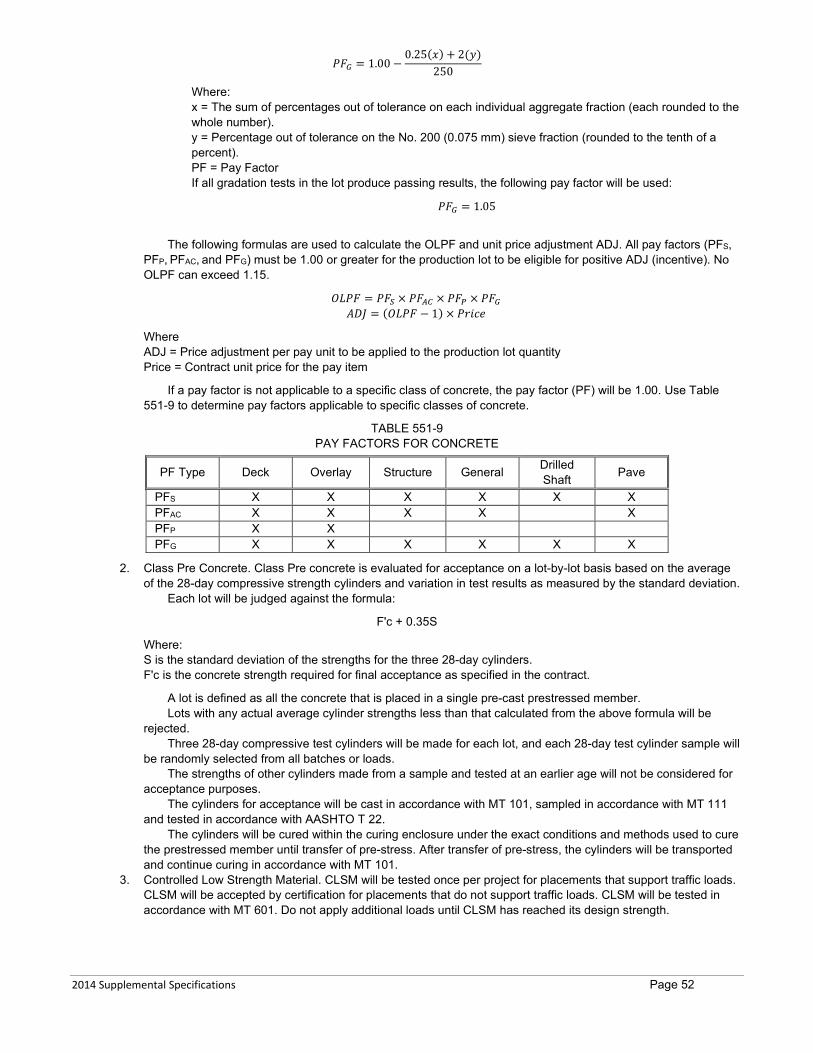
2014 Supplemental Specifications Page 52
𝑃𝑃𝑃𝑃𝐺𝐺 = 1.00 −0.25(𝑥𝑥) + 2(𝑦𝑦)
250
Where: x = The sum of percentages out of tolerance on each individual aggregate fraction (each rounded to the whole number). y = Percentage out of tolerance on the No. 200 (0.075 mm) sieve fraction (rounded to the tenth of a percent). PF = Pay Factor If all gradation tests in the lot produce passing results, the following pay factor will be used:
𝑃𝑃𝑃𝑃𝐺𝐺 = 1.05
The following formulas are used to calculate the OLPF and unit price adjustment ADJ. All pay factors (PFS, PFP, PFAC, and PFG) must be 1.00 or greater for the production lot to be eligible for positive ADJ (incentive). No OLPF can exceed 1.15.
𝑂𝑂𝑂𝑂𝑃𝑃𝑃𝑃 = 𝑃𝑃𝑃𝑃𝑆𝑆 × 𝑃𝑃𝑃𝑃𝐴𝐴𝐴𝐴 × 𝑃𝑃𝑃𝑃𝑃𝑃 × 𝑃𝑃𝑃𝑃𝐺𝐺 𝐴𝐴𝐴𝐴𝐴𝐴 = (𝑂𝑂𝑂𝑂𝑃𝑃𝑃𝑃 − 1) × 𝑃𝑃𝑃𝑃𝑃𝑃𝑃𝑃𝑃𝑃
Where ADJ = Price adjustment per pay unit to be applied to the production lot quantity Price = Contract unit price for the pay item
If a pay factor is not applicable to a specific class of concrete, the pay factor (PF) will be 1.00. Use Table 551-9 to determine pay factors applicable to specific classes of concrete.
TABLE 551-9 PAY FACTORS FOR CONCRETE
PF Type Deck Overlay Structure General Drilled Shaft Pave
PFS X X X X X X PFAC X X X X X PFP X X PFG X X X X X X
2. Class Pre Concrete. Class Pre concrete is evaluated for acceptance on a lot-by-lot basis based on the average of the 28-day compressive strength cylinders and variation in test results as measured by the standard deviation.
Each lot will be judged against the formula:
F'c + 0.35S
Where: S is the standard deviation of the strengths for the three 28-day cylinders. F'c is the concrete strength required for final acceptance as specified in the contract.
A lot is defined as all the concrete that is placed in a single pre-cast prestressed member. Lots with any actual average cylinder strengths less than that calculated from the above formula will be
rejected. Three 28-day compressive test cylinders will be made for each lot, and each 28-day test cylinder sample will
be randomly selected from all batches or loads. The strengths of other cylinders made from a sample and tested at an earlier age will not be considered for
acceptance purposes. The cylinders for acceptance will be cast in accordance with MT 101, sampled in accordance with MT 111
and tested in accordance with AASHTO T 22. The cylinders will be cured within the curing enclosure under the exact conditions and methods used to cure
the prestressed member until transfer of pre-stress. After transfer of pre-stress, the cylinders will be transported and continue curing in accordance with MT 101.
3. Controlled Low Strength Material. CLSM will be tested once per project for placements that support traffic loads. CLSM will be accepted by certification for placements that do not support traffic loads. CLSM will be tested in accordance with MT 601. Do not apply additional loads until CLSM has reached its design strength.
2014 Supplemental Specifications Page 53
4. Small Concrete Quantities. The Project Manager may accept 7 cubic yards (5.4 m3) or less of concrete without a formal mix design. Submit a batch proportion sheet to the Project Manager for approval before use. Classes Deck, Overlay, and Structure concrete are excluded from this exception.
551.04 METHOD OF MEASUREMENT Concrete is measured by the cubic yard (m3) in accordance with Subsection 552.04, unless otherwise specified. Class Pave concrete is measured for payment in accordance with Subsection 501.04. Class Pre concrete is measured for payment in accordance with Subsection 553.04. Concrete used in pre-cast concrete products is measured for payment in accordance with Subsection 554.04.
551.05 BASIS OF PAYMENT Payment for the completed and accepted quantities is made under the following:
Pay Item Pay Unit Concrete Cubic Yard (m3)
Class Pave concrete is paid for in accordance with Subsection 501.05. Class Pre concrete used in prestressed concrete members is paid for in accordance with Subsection 553.05. Concrete used in pre-cast concrete products is paid for in accordance with Subsection 554.05. Payment at the contract unit price is full compensation for all resources necessary to complete the item of work in
accordance with the contract. 552.02 MATERIALS Page 251 7-14-16 Within the list of materials, rescind only the line for Reinforcing Steel and Structural Steel and replace with the following:
Reinforcing Steel and Structural Steel 555 and 711 552.03.3 FORMS Page 251 5-25-17 Rescind the seventeenth paragraph (that begins, “Fit metal tie …”) and eighteenth paragraph (that begins, “Use metal tie …”) and replace with the following:
Furnish metal or fiberglass tie rods or anchorages within the forms with cones or other devices that permit the rod and anchorage to be removed to 1-inch (25 mm) below the surface without damaging the concrete.
Use metal or fiberglass tie fittings that leave the smallest possible size cavities. Dry pack cavities with cement mortar to produce a sound, smooth, even finished surface closely matching that of the adjacent concrete after form removal. 552.03.10 REMOVAL OF FORMS AND FALSEWORK Page 255 5-25-17 Add the following paragraph at the beginning of the Subsection, prior to the first paragraph:
Vertical forms may be removed 24 hours following the conclusion of the concrete placement. Other forms and falsework may be removed at 14 calendar days or 80% of the specified design strength. 552.03.18 SILANE SEALER Page 280 *11-14-19 Rescind the first paragraph (that begins, “Apply Silane sealer…) and replace with the following:
Apply Silane sealer to new and replacement full depth bridge decks that will not receive a polymer overlay in the same year. Apply silane sealer after the deck has been cast for at least 28 days and after transverse deck grooving is completed. 552.03.19 BRIDGE DECK CRACK SEALING Page 262 1-18-18 Add the following paragraph at the beginning of the Subsection, prior to Part (A):
Furnish bridge deck sealant in accordance with Subsection 717.02. 553.02.2 REINFORCING STEEL Page 267 7-14-16 Within first paragraph, rescind first sentence (that begins, “Furnish reinforcing steel…”) and replace with the following:

2014 Supplemental Specifications Page 54
Furnish reinforcing steel in accordance with Section 555 and Subsection 711.01.1.
553.03.1 FABRICATION Page 268 10-9-14 Add the following sentences to the end of the second paragraph, (that begins, “Furnish a copy…”):
New manufacturing plants may operate under the parent plant’s quality assurance and control programs for a maximum of 18 months from the date of opening. Plants currently operating under this exemption may do so only until January 1, 2016. 553.03.11 TRANSFER OF PRESTRESS Page 274 12-11-14 Within the tenth paragraph, rescind the second (last) sentence, (that begins, “The Project Manager may…”) and replace with the following:
The Engineer may direct other tests to determine release strengths. 554.01 DESCRIPTION Page 279 7-14-16 Rescind the first (only) paragraph and replace with the following:
This work is the furnishing and installing of reinforced precast concrete bridge members, precast curbs, cattle guard bases, and other precast concrete products.
554.03 CONSTRUCTION REQUIREMENTS Page 279 7-14-16 Add the following paragraph:
Construct any products that are not cast-in-place, and not produced at a PCI, ACPA or NPCA certified precast plant, in accordance with Subsection 605.03. These products will be evaluated on a lot-by-lot basis in accordance with 551.03.8(C) for the class of concrete specified.
556.03.1 PRE-QUALIFICATION FOR STEEL FABRICATORS Page 287 10-9-14 Rescind Subsection 556.03.1 and replace with the following:
Use metal fabricators that are pre-qualified under the AISC Quality Certification Program for the items listed below. The
Department will make an exemption for new manufacturing plants that are of the same ownership as an existing certified plant, provided the new manufacturing plant operates under the same quality assurance and control programs as the certified plants, modified to address any production differences, and all fabrication is performed under the direct supervision of a quality assurance and control manager provided by an existing pre-qualified plant. Direct supervision means that the quality assurance and control manager is on site during all fabrication performed in the new fabrication plant and is responsible for the quality assurance and control activities. For new manufacturing plants, submit and receive approval of any proposed modifications to the parent plant’s quality assurance and control program prior to beginning production. Allow 30 business days from the date submitted for Department review and approval. New manufacturing plants may operate under the parent plant’s quality assurance and control programs for a maximum of 18 months from the date of opening. Plants currently operating under this exemption may do so only until January 1, 2016. Items not listed may be fabricated by non-certified shops. Use metal fabricators having the following AISC quality certification categories:
1. Use fabricators having Advanced Bridges (ABR) certification to fabricate the following: a. Fracture critical members and attachments. Fabricators must have the fracture critical endorsement (F). b. Tub, trapezoidal or closed box girders, large or non-preassembled trusses [over 200 feet (60 m)], cable
supported bridges, bascule bridges, arches and bridges with tight radius. 2. Use fabricators having Intermediate Bridges (IBR) certification to fabricate the following:
a. Fracture critical members and attachments. Fabricators must have the Fracture Critical Endorsement (F). b. Rolled beams with field or shop splices, either straight or with a radius over 500 ft. c. Built-up I-shaped plate girders with constant depth, either straight or with a radius over 500 feet (150 m). d. Built-up I-shaped plate girders with variable web depth (e.g., haunched), either straight or with a radius over
1000 feet (305 m). e. A truss with a length of 200 feet (60 m) or less that is entirely or substantially pre-assembles at a certified facility
and shipped in no more than three sub-assemblies. f. Welded floor beams.
2014 Supplemental Specifications Page 55
g. Diaphragms for horizontally curved girders. 3. Use fabricators having Simple Bridges (SBR) certification to fabricate the following:
a. Non-spliced rolled beams. b. Non-spliced rolled floor beams. c. Non-spliced rolled diaphragms for straight girders (does not include diaphragms used for concrete beams).
4. Use fabricators having an SBR or Bridge and Highway Metal Component Manufacturers certification to fabricate the following: a. Bridge expansion joints. b. Steel grid decking. c. Bridge expansion bearings. d. Overhead sign bridge and cantilever sign structures. e. Lighting poles and anchor bases.
556.03.5 QUALITY CONTROL Page 290 1-18-18 Within Subsection 556.03.5 add the following Part (6) following Part (5):
3. NDT, Phased Array Ultrasonic Testing (PAUT). This method may be used in place of RT and UT for the inspection of CJP groove welds. Perform all aspects of PAUT inspection in accordance with AWS D1.5, Annex K. Provide for approval, a submittal package 30 days prior to inspection. Provide all information, qualifications, etc. needed to determine the requirements of Annex K can be met. Include the inspector’s history of successful NDT projects specific to PAUT and the requirements of AWS D1.5.
556.03.8 BOLTED CONNECTIONS - HIGH-TENSILE-STRENGTH BOLTS Page 291 1-18-18 Within Part (A)(2), rescind the third (last) paragraph (that begins, “Provide a Class…”) and replace with the following:
Provide a Class B finish, per AASHTO LRFD Bridge Construction Specifications for all faying surfaces. Within Part (D), row 2 of Table 556-2 – Bolt Substitutions, rescind, “ASTM A325M” and replace with “Grade A325M or Grade A490M”. Within Part (D) row 2 of Table 556-2 – Bolt Substitutions, rescind, “ASTM A325” and replace with “Grade A325 or Grade A490”. 556.03.11 ASSEMBLING STEEL Page 315 *11-14-19 Within Part B. Field Work, add the following sentence to the end of the third paragraph (that begins, “Do not begin…):
Do not place deck forms or other loads on straight steel girders until all girder splice bolts are fully tensioned. For curved structures, fully tension all bolts before placing deck forms or other loads. 558.02.3 REINFORCING STEEL Page 299 7-14-16 Add the following Subsection:
558.02.3 Reinforcing Steel Furnish all reinforcing steel in accordance with Section 555 and Subsection 711.01.
558.03.1 SUBMITTALS Page 299 7-14-16 Within Part A, rescind Number 3 (that begins, “Method to clean…”) and replace with the following:
3. Methods to clean shaft excavation including details for air-lift systems. Rescind Part B (that begins, “Name and experience…”) and replace with the following:
B. Name and experience record of Contractor, and Superintendent and driller(s) that will perform the drilled shaft work on this project. Include all experience in the last 10 years.

2014 Supplemental Specifications Page 56
558.03.4 SHAFT EXCAVATION Page 300 7-14-16 Within the first paragraph, rescind the first sentence (that begins, “Use excavation methods…”) and replace with the following:
Use excavation methods that provide contact with firm, undisturbed soil or rock with the sides and bottom of the drilled shaft.
558.03.7 PERMANENT CASING Page 300 7-14-16 Add the following Bullet D:
D. Limit the excavation in advance of the casing tip to no more than 10 feet (3 m) unless synthetic slurry is being used. 558.03.8 TEMPORARY CASING Page 301 7-14-16 Rescind Subsection 558.03.8 and replace with the following:
558.03.8 Excavation Stability Do not use slurry construction methods as an alternative to or in conjunction with temporary casing unless specified
in the contract. Use casings to facilitate shaft construction and prevent sloughing and caving of the shaft sidewalls. The contract may specify temporary casing minimum elevations. Place the temporary casing(s) deeper if necessary to prevent material from entering the shaft excavation. Use casing with an outside diameter no less than the specified diameter of the shaft. Limit the excavation in advance of the casing tip to no more than 10 feet (3 m) unless synthetic slurry is being used. During casing extraction, maintain a sufficient level of fluid in the casing to counteract external hydrostatic pressures but no less than 5 feet (1.5 m) of positive head. Maintain an adequate level of concrete within the casing to ensure that fluid trapped behind the casing is displaced upward and discharged at the ground surface without contaminating or displacing the shaft concrete. Temporary casings that have become bound or fouled during shaft construction and cannot be removed are considered to be a defect in the drilled shaft. Correct defective shafts using approved methods at no cost to the Department. Corrective action may consist of, but is not limited to, the following:
1. Removing the drilled shaft concrete and extending the drilled shaft deeper to compensate for the loss of frictional capacity to the cased zone. 2. Providing straddle drilled shafts to compensate for capacity loss. 3. Providing a replacement drilled shaft.
558.03.10 CLEANING Page 301 7-14-16 Rescind Subsection 558.03.10 and replace with the following:
558.03.10 Cleaning Remove all loose or disturbed material from the bottom of the shaft excavation immediately prior to placing
reinforcing steel and concrete. After cleaning, no more than 1-inch (25 mm) of loose or disturbed material is permitted in the bottom of the shaft.
For wet shafts founded in rock, use an air lift to demonstrate that the shaft is clean. Use an air-lift system meeting the following requirements:
1. Sufficient length to discharge outside of the shaft; 2. Minimum of 4-inch (100 mm) diameter; 3. Compressed air input line located within 12 inches (300 mm) of the bottom of the lift pipe. 4. Air compressor capable of producing 185 CFM at 100 psi (5.2 m3/min at 6.9 bar). 5. Meet all applicable environmental requirements relating to discharge. During final cleanout and until concrete placement is complete, maintain the fluid level within the shaft at a level of 5
feet (2 m) or more higher than the water level present outside of the shaft. 558.03.11 INSTALLATION OF CROSS-HOLE SONIC LOGGING (CSL) TUBES Page 301 7-11-19 Rescind the first paragraph and replace with the following:
Use 1½-inch (38 mm) nominal diameter schedule 40 steel CSL access tubes. Provide an end plug at the lower end of the pipe and make all joints watertight. Install the CSL access tubes evenly spaced around the reinforcing cage and inside of hoops and spiral reinforcing steel shown in the contract, using connectors that will allow the tubes to slide through them when force is applied. Position the connectors so that couplings will not prevent the tubes from sliding. Ensure tubes extend to the shaft bottom. After inserting the shaft reinforcing steel, drive each tube down until contact is made with the shaft bottom. Fill the CSL access tubes with potable water prior to or immediately after placing concrete in the drilled shaft. Temporarily cap the top of the tubes to prevent debris or concrete from entering the tubes.
2014 Supplemental Specifications Page 57
558.03.12 REINFORCING STEEL Page 302 7-14-16 Within the first paragraph, rescind the fifth sentence(that begins, “Use non-corrosive…”) and replace with the following:
Use non-corroding, roller-type spacers or other non-corroding devices as approved by the Project Manager along the steel cage length and around the steel cage perimeter to align and maintain clearance from reinforcing cage to edge of casing during concrete placement.
Within the first paragraph, rescind the seventh (last) sentence(that begins, “Remove the steel…”) and replace with the following:
Remove the steel cage and re-inspect the excavation as directed by the Project Manager if the concrete placement is not started within 3 hours of placing the steel cage in position.
558.03.15(A) CROSS-HOLE SONIC LOGGING Page 302 7-11-19 Within the first paragraph, rescind the fifth sentence (that begins, “When the CSL…”) and the sixth sentence (that begins, “Permanently cap the…”) replace with the following:
When the CSL testing access tubes are no longer needed for testing, as determined by the Project Manager, cut off the tubes flush with the top surface of the drilled shaft. Remove water and fill CSL tubes with grout. Protect tubes from freezing until water is removed.
558.04.6 CSL TUBES AND TESTING Page 303 7-11-19 Rescind Subsection 558.04.6 and replace with the following:
558.04.6 CSL Tubes and Testing Include all costs associated with furnishing and installing, and grouting CSL access tubes and any required
extensions and providing a power source in the Drilled Shaft pay item. No measurement or payment will be made for construction delays resulting from the initial CSL drilled shaft testing. The Department will extend the contract time by 1 day for each day over 12 calendar days required to complete the CSL drilled shaft testing. The Department will pay the costs for the initial CSL drilled shaft testing.
If a defect is found based on the CSL drilled shaft testing, coring, or other physical investigation, the contractor is responsible for all costs associated with the physical investigation, engineering design, shaft repairs, and any construction delay costs. Pay the costs of CSL drilled shaft retesting of the repaired drilled shafts.
If no defect is found in the drilled shaft based on the physical investigation, the investigation will be considered extra work, and paid for in accordance with Subsection 109.04, and considered for time adjustment in accordance with Subsection 108.07.
558.05 BASIS OF PAYMENT Page 304 7-14-16 Add the following paragraph following the last paragraph:
Air-lifting is not measured separately for payment. Include costs for all airlifting in the Drilled Shaft Item. 559.03.3 PILE BEARING RESISTANCE Page 307 4-25-19 Within Part A, rescind the third sentence (that begins, “The Department will…”) and replace with the following:
The Department will determine required bearing resistance based on a wave equation analysis. Within Part (B)(2), within the forth paragraph, rescind the second sentence (that begins, “After initial…”) and replaxce with the following:
After initial driving, wait 48 hours or longer if directed by the Project Manager, then re-drive each dynamic load test pile with the instruments attached.
559.03.5 SERVICE PILE Page 310 4-25-19
2014 Supplemental Specifications Page 58
Within the fourth paragraph rescind the first sentence (that begins, “When a re-drive…”) and replace with the following:
When a re-drive of the service pile is required, re-drive the pile 48 hours after initial driving, or longer if directed by the Project Manager, and do not drive the pile below cut off elevation.
561.03.3 PROCEDURES Page 313 10-9-14 Under (A) Hydrodemolition, rescind the third paragraph (that begins, “Remove any remaining…”). Following Subsection (B), rescind the first and second paragraphs (that begins, “Remove concrete in…”) and replace with the following:
Remove concrete, in areas designated for removal that milling equipment cannot reach, with chipping hammers no larger than a nominal 15 pound (7 kg) class or other equipment as approved by the Project Manager. This work is measured and paid for as Bridge Deck Milling.
Thoroughly clean the deck of all aggregate, paste, residue, oil, and any other substance that may interfere with the repair or overlay concrete. Use cleaning methods that do not damage remaining concrete, reinforcing steel, or that cause debonding of remaining concrete and reinforcing steel. 561.04 METHOD OF MEASURMENT Page 314 7-14-16 Within the first paragraph, rescind the first sentence (that begins, “Bridge deck milling…”) and replace with the following:
Bridge deck milling is measured by the square yard (m2) of deck surface removed. 562.02.1 REINFORCING STEEL Page 315 7-14-16 Add the following Subsection:
562.02.1 Reinforcing Steel Furnish all reinforcing steel in accordance with Section 555 and Subsection 711.01.
562.03.3 LOCATION AND INSPECTION OF REPAIR AREAS Page 315 10-9-14 Rescind bullets 1, 2 and 3 and replace with the following:
1. Complete milling operations, if included in the contract, prior to the locating of Class A or B repair areas 2. Use compressed air to dry the deck and to blow it clean of debris. The Project Manager will then locate and mark
areas of Class A and Class B deck repair. 3. Notify the Project Manager if repair work reveals areas which differ from the marked areas.
562.03.4 CONCRETE REMOVAL Page 315 10-9-14 Within bullet 2, rescind the third sentence (that begins, “If the bond…). 562.03.5 REINFORCING STEEL Page 316 10-9-14 Within the first paragraph, rescind the second (last) sentence (that begins, “Remove concrete as…). 562.04 METHOD OF MEASUREMENT Page 317 10-9-14 Rescind the fourth (last) paragraph (that begins, “Replacement of reinforcing…) and replace with the following:
Replacement of reinforcing bars will be measured and paid for in accordance with Subsection 109.04. Replace any reinforcing bars damaged by Contractor operations at Contractor expense. When not located in an area of Class A or B repair, work necessary to provide reinforcement clearance in accordance with Subsection 562.03.5 will be measured and paid for in accordance with Subsection 109.04.
2014 Supplemental Specifications Page 59
563.02.2 AGGREGATE Page 319 4-25-19 Rescind the bullet 2 (that begins, “Furnish ¾-inch…) and replace with the following:
2. Furnish aggregate in accordance with Table 551-3. Within Part (4), replace MT 221 with AASHTO T 255. 563.05 BASIS OF PAYMENT Page 322 7-14-16 Following the first paragraph, rescind the Pay Item/Pay Unit Table and replace with the following:
Pay Item Pay Unit Concrete – Class Overlay Cubic Yard (m3)
564.03 CONSTRUCTION REQUIREMENTS Page 323 3-10-16 Within Table 564-1, within the row showing Substructure: Walls, Footings, Columns, rescind the row showing Deviation from Plumb and replace with the following:
Substructure: Walls, Footings, Columns Deviation from Plumb ±0.2%
Within Table 564-1, rescind the row showing Pre-Stressed Concrete Beam requirements and replace with the following:
Pre-Stressed Concrete Beams Refer to Subsection 553.03.15
602.04.2 RELAY PIPE CULVERTS Page 331 7-14-16 Rescind Subsection 602.04.2 and replace with the following:
602.04.2 Relay Pipe Culverts Relay pipe culvert is measured by the foot (meter) along the flowline of the re-laid lengths. Excavation required to relay pipe culverts is not measured separately for payment.
603.03.4 BACKFILLING Page 336 2-26-15 Add the following sentence at the end of the fourth paragraph (which begins “Compact backfill equally…”):
Meet the moisture and density requirements of Subsection 203.03.3. 603.03.5 RESTORATION AND MAINTENANCE OF EXISTING PAVEMENT Page 336 2-26-15 Rescind Subsection 603.03.5 and replace with the following:
Restore the existing pavement excavated for pipe installation using material equal to or better than the in place pavement. Restoration includes replacing and compacting excavated aggregate base with materials equal to those in the existing roadway and placing either CLSM or new plant mix surfacing equal to the existing, but not less than 3 inches (75 mm) in thickness. Place and compact the replacement plant mix surfacing to match the adjacent pavement providing a smooth riding surface, including the joints.
Maintain the restored areas in good condition until the new surfacing is placed. 603.04.3 BEDDING AND FOUNDATION MATERIAL Page 337 12-08-12 Rescind the title of Subsection 603.04.3 and replace with the following: 603.04.3 GRANULAR BEDDING, BEDDING AND FOUNDATION MATERIAL Rescind and replace the first paragraph with the following:

2014 Supplemental Specifications Page 60
Bedding material is measured by the cubic yard (m3) in place for pipes greater than 48-inch (1.2 m) diameter, and for all sizes of storm drain trunklines and laterals. Include the cost of bedding material for pipes 48-inch (1.2 m) diameter or less in the cost of the pipe. Foundation material is measured by the cubic yard (m3) in place. 603.04.5 GRANULAR BEDDING MATERIAL FOR STORM DRAINS Page 337 12-8-16 Rescind Subsection 603.04.5. 604.02.3 REINFORCING STEEL Page 339 7-14-16 Within first paragraph, rescind first sentence (that begins, “Furnish reinforcing steel…”) and replace with the following:
Furnish reinforcing steel in accordance with Section 555 and Subsection 711.01.1. 605 CONCRETE BARRIER RAIL Page 341 *11-14-19 Add the following Section 605:
SECTION 605 CONCRETE BARRIER RAIL
605.01 DESCRIPTION This work is the constructing and installation of concrete barrier rail.
605.02 MATERIALS 605.02.1 Concrete
Furnish Class Deck concrete in accordance with Section 551. 605.02.2 Reinforcing Steel
Furnish reinforcing steel in accordance with Section 555 and Subsection 711.01. 605.03 CONSTRUCTION REQUIREMENTS 605.03.1 Fabrication Submittals
Submit the following information to the Project Manager 10 business days prior to casting members: 1. A tentative fabrication schedule; 2. A mix design in accordance with Section 551; 3. The product data sheet for proposed cure and seal product. 4. Any other information necessary to fabricate and install the product. Do not begin fabrication until the Department approved submittals are received by both the Contractor and the Project
Manager. Coordinate the fabrication schedule with the Project Manager.
605.03.2 Sampling, Handling, Batching, and Mixing
Sample, handle, batch, and mix materials for concrete in accordance with Subsection 551.03.3. 605.03.3 Forms and Forming
Meet the form requirements in Subsection 552.03.3. 605.03.4 Placing Concrete
Place concrete in accordance with Subsection 552.03.4 and 551.03.5. 605.03.5 Weather and Temperature Limitations.
Meet the requirements of Subsection 551.03.6 when constructing concrete barrier rail in hot or cold weather conditions. 605.03.6 Curing Concrete Barrier Rail
Cure concrete barrier rail in accordance with 551.03.7 using material in accordance with Subsection 717.01.4 requirements. 605.03.7 Testing and Acceptance of Concrete Barrier Rail
A. Sampling and Testing. Meet all requirements of Subsection 551.03.8(B). B. Acceptance of Concrete Barrier Rail. Concrete Barrier Rail is evaluated on a lot-by-lot basis in accordance with
551.03.8(C) for Class Deck Concrete except for the following: 1. An individual lot is defined as 30 concrete barrier rail units or one day’s production, whichever is less. 2. A minimum of one standard compressive strength set will be made for each lot.

2014 Supplemental Specifications Page 61
605.03.8 Form Removal
Remove lateral support forms only when it does not damage the concrete. Do not interrupt curing and protection in excess of 30 minutes for form removal. Replace all damaged units at Contractor expense. 605.03.9 Finish on Exposed Surfaces
Apply an ordinary finish to surfaces not smooth and uniform in texture and appearance in accordance with Subsection 552.03.11. 605.03.10 Handling, Transporting, and Storage
Include on each fabricated piece of barrier rail a permanent identification number representing the date fabricated and Lot number associated with that days pour. Place the number in the same location on each piece. The ID must be visible when the barrier rail is pinned and in place on the project.
The number may be cast into the concrete or attached after the curing period is complete. Numbers must be legible. Notify the Department when forms will be stripped, and markings applied. All numbers must be verified by inspection
within 48 hours of removal of forms. Track all barrier rail supplied to Department projects. Submit to the Project Manager the lots and identification numbers representing all barrier rail to be included for the project.
The concrete barrier rail may be moved from the casting area to an adjacent staging area when they have reached 75% of design strength and the strength is adequate to prevent damage. Replace all cracked or broken items at Contractor expense.
Handle, transport, and store precast concrete items without damage. Replace or repair all damaged units at Contractor expense. Transport the concrete barrier rail from their casting or adjacent staging location only after strength tests indicate the lot they represent has reached the design strength. If shipping is desired before the Department’s 28-day acceptance tests are performed, supply compressive strength results representing the lot of concrete to the Department indicating design strength has been met. Ensure this testing is conducted by an ACI certified technician. Final acceptance of the concrete barrier rail will be based on the Department’s test results for acceptance. 605.03.11 Install Concrete Barrier Rail
Install concrete barrier rail meeting the contract requirements and the Detailed Drawings. 605.03.12 Reset Concrete Barrier Rail
Reset concrete barrier rail as specified in the contract. 605.04 METHOD OF MEASUREMENT 605.04.1 Concrete Barrier Rail
Concrete barrier rail is measured by each 10-foot (3.05 m) section. Connections to the existing barriers are included in the cost of the rail.
Measurement does not include those portions of barrier constructed as an integral part of sign foundations. 605.04.2 Reset Concrete Barrier Rail
Reset concrete barrier rail is measured by each 10-foot (3.05 m) section. 605.04.3 Concrete Barrier Rail Transition
Concrete barrier rail transitions are measured by each 10-foot (3.05 m) section. 605.04.4 Concrete Barrier Rail Terminal Section
Concrete barrier rail terminal sections are measured by each 10-foot (3.05 m) section. 605.04.5 Remove Concrete Barrier Rail
Remove concrete barrier rail is measured by each 10-foot (3.05 m) section. 605.05 BASIS OF PAYMENT
Payment for the completed and accepted quantities is made under the following: Pay Item Pay Unit Concrete Barrier Rail Each Concrete Barrier Rail Transition Each Concrete Barrier Rail Terminal Section Each Remove Concrete Barrier Rail Each
Payment at the contract unit price is full compensation for all necessary resources to complete the item of work in
accordance with the contract. 606 GUARDRAIL AND CONCRETE BARRIER RAIL Page 341 3-10-16 Rescind the title only of Section 606 and replace with the following:
2014 Supplemental Specifications Page 62
SECTION 606 GUARDRAIL
606.01 DESCRIPTION Page 341 3-10-16 Rescind the first (only) paragraph (that begins, “The work is…) and replace with the following:
This work is the furnishing, installing, removing, resetting, replacing and revising metal beam guardrail, cable guardrail, and box beam guardrail. 606.02 MATERIALS Page 341 3-10-16 Rescind the first paragraph (that begins, “Furnish metal beam…) and replace with the following:
Furnish metal beam guardrail, cable guardrail, and box beam guardrail materials in accordance with the following section and subsection requirements: Within the list of materials, rescind only the line shown below:
Concrete Barrier Rail ................................................................. 554 606.03.1 GENERAL Page 341 3-10-16 Within the first paragraph, rescind the first sentence (that begins, “Install guardrail and…) and replace with the following:
Install guardrail meeting the requirements of Detailed Drawings and the contract. 606.03.2 INSTALLING POSTS Page 342 12-11-14 Rescind the first paragraph (that begins, “If the posthole is…) and replace with the following:
Complete guardrail widening prior to new post installation. Install posts in accordance with manufacturer recommendations. Drive posts unless conditions require excavation and
backfilling. If the posthole is excavated, compact the posthole bottom, insert the post, and backfill and compact around the post in 6-inch (150 mm) loose layers ensuring the material is at optimum moisture before placing and compacting the next layer. Maintain the post line and grade. Rescind the second paragraph (that begins, “Always drive steel …”). 606.03.3 METAL BEAM GUARDRAIL ERECTION Page 342 5-25-17 Within the first paragraph, rescind the second sentence (that begins, “Locate all rail…): 606.03.7 CONCRETE BARRIER RAIL Page 342 3-10-16 Rescind Subsection 606.03.7 and replace with the following:
606.03.7 Reserved 606.04.9 CONCRETE BARRIER RAIL Page 344 3-10-16 Rescind Subsection 606. 04.9 and replace with the following:
606.04.9 Reserved 606.04.12 CONCRETE BARRIER RAIL TRANSITION Page 344 3-10-16
2014 Supplemental Specifications Page 63
Rescind Subsection 606. 04.12 and replace with the following:
606.04.12 Reserved 606.04.13 CONCRETE BARRIER RAIL TERMINAL SECTION Page 344 3-10-16 Rescind Subsection 606. 04.13 and replace with the following:
606.04.13 Reserved 606.04.16 REMOVE CONCRETE BARRIER RAIL Page 344 3-10-16 Rescind Subsection 606. 04.16 and replace with the following:
606.04.16 Reserved 606.05 BASIS OF PAYMENT Page 345 3-10-16 Remove the following pay items and units from the table:
Pay Item Pay Unit Concrete Barrier Rail Each Concrete Barrier Rail Terminal Section Each Concrete Barrier Rail Transition Each Remove Concrete Barrier Rail Each
607.03.3(B) TOP RAIL OR CABLE Page 348 3-10-16 Rescind Subsection 607.03.3(B) and replace with the following:
B. Top Cable or Rail. Furnish a ⅜-inch (10 mm) diameter galvanized steel cable for the top brace. Pass the top cable through the line post tops, providing a continuous brace from end-to-end of each fence section.
Use a top rail in place of the top cable when fences are used in low speed residential applications. Join top rail sections using sleeve-type couplings. Fasten the top rails to the terminal posts using pressed steel fittings.
608.02 MATERIALS Page 353 7-14-16 Within the list of materials, rescind only the line rescind the line for Reinforcing Steel and replace with the following:
Reinforcing Steel 555 and 711.01 Rescind the second, third, and fourth (last) paragraphs of Subsection 608.02 and replace with the following:
Use cast iron DWDs having a natural grey finish. Use DWDs – Type 1 for new sidewalk construction. DWDs – Type 1 are cast directly into sidewalk. Use DWDs – Type 2 for retrofits on existing sidewalks. Ensure gray iron castings are manufactured from iron conforming to ASTM A48 Class 30B, as noted in AASHTO M 306. Ensure ductile iron castings are manufactured from iron conforming to ASTM A536 Grade 80-55-06
Furnish DWDs listed on the QPL. 608.03.3 DETECTABLE WARNING DEVICES Page 353 4-16-15 Rescind Subsection 608.03.3 and replace with the following: 608.03.3 Detectable Warning Devices
A. General. Install DWDs so they extend the full width of the ramp, and the edge of the dome panel is located no more than 6 inches (150 mm) from the back of curb. Ensure that DWD edges are flush with adjacent sidewalk without gap
2014 Supplemental Specifications Page 64
or lip, with domes protruding above adjacent surfaces. If DWDs require cutting, locate non-factory edges on the exterior side of DWD installation.
B. Type 2. Saw cut from existing sidewalk the minimum area required to allow installation. Remove the old sidewalk full depth within the cut area. Place new concrete meeting Section 608 requirements, and install DWD in accordance with manufacturer recommendation.
608.04 METHOD OF MEASURMENT Page 353 4-16-15 Rescind the second paragraph of (that begins, “DWDs are measured…”) and replace with the following:
DWDs are measured by the square yard (m2) installed and accepted. For Type 2 DWDs, removal of existing devices, concrete sawing and removal, and all new concrete is not measured separately for payment. 609.03.6 BITUMINOUS CURBS Page 356 12-11-14 Rescind Subsection 609.03.6 and replace with the following: 609.03.6 Reserved 610.02 MATERIALS Page 359 10-9-14 Add the following material to the existing table:
Weed Control Mat ..................... 713.06 610.03.2 SEEDING, FERTILIZING, AND MULCHING Page 359 8-6-15 Add the following sentence to the end of Bullet (B) Seeding Season:
If contract time has been stopped awaiting the seeding season, contract time assessment will resume when the seeding begins or October 15th, whichever occurs first. Add the following sentence to the end of Bullet (G) Composting:
Compost rates are dry weight equlivalent. 610.03.4 EROSION CONTROL BLANKET Page 362 2-26-15 Rescind the title of Subsection 610.03.4 and replace with the following:
610.03.4 Rolled Erosion Control Products Within the first paragraph, rescind the first sentence (that begins, “Prepare, fertilize, and seed…”) and replace with the following:
Prepare, fertilize, and seed the rolled erosion control products areas before placement. 610.03.5 WEED CONTROL MAT Page 362 10-9-14 Add the following Subsection: 610.03.5 Weed Control Mat
Handle and place weed control mat following the manufacturer’s recommendations. 610.04.7 SOIL RETENTION BLANKET Page 363 2-26-15 Rescind Subsection 610.04.7 and replace with the following: 610.04.7 Rolled Erosion Control Products

2014 Supplemental Specifications Page 65
Rolled Erosion Control Products is measured by the square yard (m2) in place. 610.04.9 WEED CONTROL MAT Page 363 10-9-14 Add the following Subsection: 610.04.9 Weed Control Mat
Weed control mat is measured by the square yard (m2) in place. 610.05 BASIS OF PAYMENT Page 363 2-26-15 Rescind and replace the pay item “Soil Retention Blanket” with “Rolled Erosion Control Products” Add the following pay item and unit to the end of the existing table:
Pay Item Pay Unit Weed Control Mat Square Yard (m2)
611.02.1 CONCRETE Page 365 9-20-18 Rescind Subsection 611.02.1 and replace with the following:
611.02.1 Concrete Furnish air-entrained hydraulic cement concrete in accordance with Section 551 for precast bases.
611.03.2 PLACING CONCRETE BASES Page 365 9-20-18 Rescind the first paragraph of Subsection 611.03.2 (that begins, “Construct poured-in-place…”) 612.03 CONSTRUCTION REQUIREMENTS Page 367 1-18-18 Prior to the first paragraph, add the following:
Paint all new structural steel surfaces, except those noted in Subsection 612.03.3(C)1. Do not paint weathering steel unless specifically stated. 612.03.3(C)(1) SHOP PAINT Page 369 10-9-14 Within the first paragraph, rescind the second sentence (that begins, “Do not paint…”) and replace with the following:
Do not paint surfaces in contact with other metal surfaces or concrete, except as noted in Subsection 612.03.5(A). 613.03.4 CONCRETE DRAINAGE CHUTES Page 374 10-9-14 Rescind Subsection 613.03.4 and replace with the following: 613.03.4 Drainage Chutes
Construct drainage chutes as shown in the Detailed Drawings. 617.03.11 SERVICE AND CONTROL ASSEMBLY Page 389 7-14-16 Within the second paragraph, rescind the fourth (last) sentence (that begins, “Include the cost…”) and replace with the following:
Include the cost of the 6 x 6 inch (150 x 150 mm) wood post, if necessary, as part of the service assembly bid item. Full length pressure-treat all S4S timber posts and poles in accordance with Subsection 706.04.

2014 Supplemental Specifications Page 66
618.03.5 TRAFFIC CONTROL GENERAL REQUIREMENTS Page398 12-8-16 Rescind and replace the first paragraph with the following:
Meet all traffic control plan requirements before starting work affecting the roadway. Furnish and maintain traffic control devices that meet the “acceptable” category described in Quality Guidelines for Temporary Traffic Control Devices and Features published by ATSSA. Repair or remove and replace “marginal” devices with 24 hours; and repair or remove and replace “unacceptable” devices immediately. Anything in the worse-than-marginal conditions is not acceptable. Do not deliver devices in the “unacceptable” category to the jobsite. 618.03.8 TRAFFIC CONTROL AT DROP-OFF AREAS Page 436 *11-14-19 Rescind Table 618-4 and replace with the following:
TABLE 618-4 TRAFFIC CONTROL DEVICE BASED ON SPACING FACTOR
Spacing Factor Device Type 400 feet (122 m) or greater Flexible guideposts or standard delineators 20 to 390 feet (6 to 119 m) Type 2 object marker Less than 20 feet (6 m) Positive barrier, if 48 hours lapses before filling
Rescind the last paragraph (that begins, “ Do not space..”). 618.03.12 TRAFFIC CONTROL FOR STRIPING OPERATIONS Page 402 10-9-14 Rescind Subsection 618.03.12 and replace with the following: 618.03.12 Traffic Control for Striping and Sweeping Operations
Provide the following traffic control for striping and final sweep and broom operations not performed under closed lane or pilot car situations.
1. Furnish and operate a shadow vehicle equipped with a truck or trailer-mounted attenuator in accordance with Subsection 618.02 conforming to appropriate test levels. Position the truck to follow within 150 to 1,000 feet (45 - 305 m) on pavement marking removal and application, and sweeping and brooming. When placing or removing traffic cones that protect the pavement markings, use a vehicle with a truck-mounted attenuator or follow with a shadow vehicle possessing a truck mounted attenuator.
2. Equip shadow vehicles with an arrow board facing rear-approaching traffic. a. On multiple-lane roadways, place the arrow board display in lane shift mode (sequential arrow mode). b. On two-lane two-way roadways, place the arrow board in a hazard warning mode not displaying the lane-shift
mode 3. If peak hours are specified in the contract, provide the Project Manager a schedule of striping and final sweep and
broom operations at least 48 hours prior to work. Perform work during off-peak hours in order to minimize impacts to the traveling public unless approved differently by the Project Manager.
4. For striping operations, include all costs associated with this work in the striping bid item. 5. If requested by the Project Manager, provide a WN identifying the proposed traffic control devices to be used for
striping or final sweep and broom operations. If the Contractor and Project Manager agree that additional traffic control devices not listed in items 1 through 3 are warranted; the additional traffic control devices will be measured and paid in accordance with Subsections 618.04 and 618.05.
Failure to properly notify the Project Manager or provide adequate traffic control renders the striping or final sweep and broom operation unacceptable and unauthorized. Unacceptable or unauthorized work will be addressed in accordance with Subsection 105.12. 618.03.13 TRAFFIC CONTROL DEVICE LOCATION AND INSTALLATION Page 403 *11-14-19 Rescind the 12th paragraph (that begins, “Do not use flexible guide posts”). Within the ‘Existing’ row of Table 618-5, replace ‘winter shutdown’ with ‘winter suspension’.
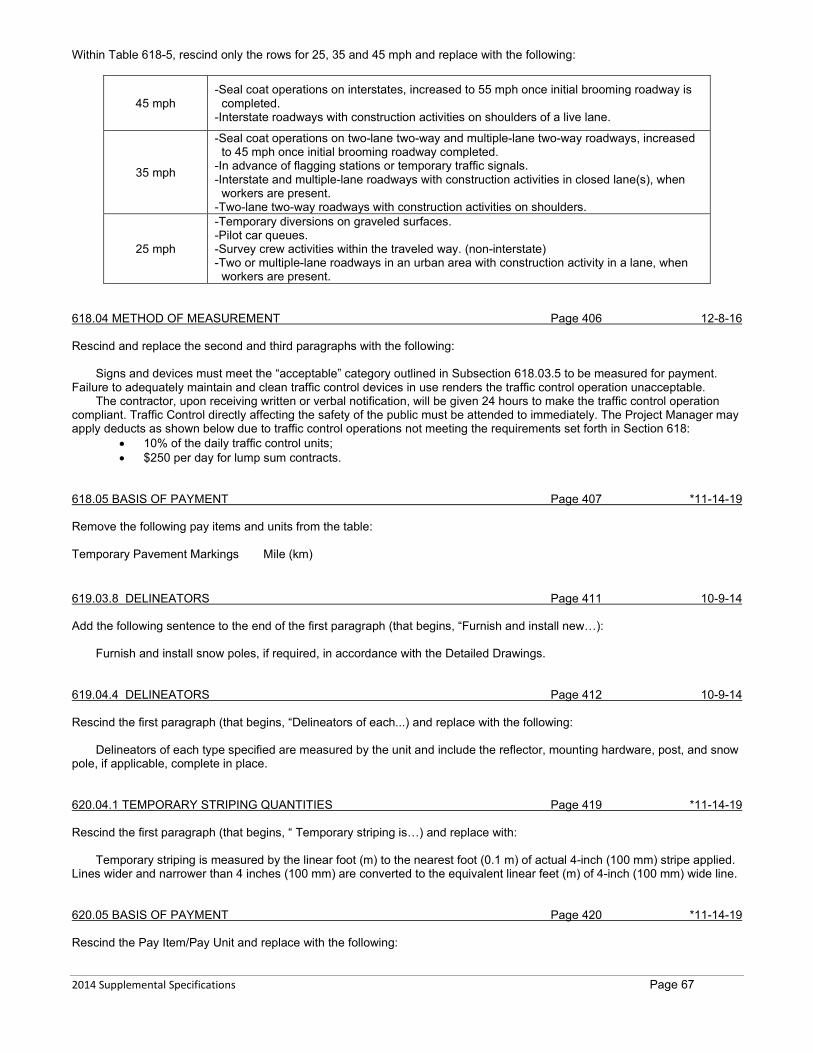
2014 Supplemental Specifications Page 67
Within Table 618-5, rescind only the rows for 25, 35 and 45 mph and replace with the following:
45 mph -Seal coat operations on interstates, increased to 55 mph once initial brooming roadway is
completed. -Interstate roadways with construction activities on shoulders of a live lane.
35 mph
-Seal coat operations on two-lane two-way and multiple-lane two-way roadways, increased to 45 mph once initial brooming roadway completed.
-In advance of flagging stations or temporary traffic signals. -Interstate and multiple-lane roadways with construction activities in closed lane(s), when
workers are present. -Two-lane two-way roadways with construction activities on shoulders.
25 mph
-Temporary diversions on graveled surfaces. -Pilot car queues. -Survey crew activities within the traveled way. (non-interstate) -Two or multiple-lane roadways in an urban area with construction activity in a lane, when
workers are present. 618.04 METHOD OF MEASUREMENT Page 406 12-8-16 Rescind and replace the second and third paragraphs with the following:
Signs and devices must meet the “acceptable” category outlined in Subsection 618.03.5 to be measured for payment. Failure to adequately maintain and clean traffic control devices in use renders the traffic control operation unacceptable.
The contractor, upon receiving written or verbal notification, will be given 24 hours to make the traffic control operation compliant. Traffic Control directly affecting the safety of the public must be attended to immediately. The Project Manager may apply deducts as shown below due to traffic control operations not meeting the requirements set forth in Section 618:
• 10% of the daily traffic control units; • $250 per day for lump sum contracts.
618.05 BASIS OF PAYMENT Page 407 *11-14-19 Remove the following pay items and units from the table: Temporary Pavement Markings Mile (km) 619.03.8 DELINEATORS Page 411 10-9-14 Add the following sentence to the end of the first paragraph (that begins, “Furnish and install new…):
Furnish and install snow poles, if required, in accordance with the Detailed Drawings. 619.04.4 DELINEATORS Page 412 10-9-14 Rescind the first paragraph (that begins, “Delineators of each...) and replace with the following:
Delineators of each type specified are measured by the unit and include the reflector, mounting hardware, post, and snow pole, if applicable, complete in place. 620.04.1 TEMPORARY STRIPING QUANTITIES Page 419 *11-14-19 Rescind the first paragraph (that begins, “ Temporary striping is…) and replace with:
Temporary striping is measured by the linear foot (m) to the nearest foot (0.1 m) of actual 4-inch (100 mm) stripe applied. Lines wider and narrower than 4 inches (100 mm) are converted to the equivalent linear feet (m) of 4-inch (100 mm) wide line. 620.05 BASIS OF PAYMENT Page 420 *11-14-19 Rescind the Pay Item/Pay Unit and replace with the following:

2014 Supplemental Specifications Page 68
Temporary Striping Linear Foot (m) 622.03.3 SUBSURFACE DRAINAGE GEOTEXTILE FILTER Page 425 10-9-14 Within the fifth paragraph, rescind the second (last) sentence (that begins, “If a perforated…). 623.02 MATERIALS (MAILBOXES) Page 429 12-11-14 Within the first paragraph, rescind the first sentence (that begins, “Use mailboxes listed…) and replace with the following:
Use metal mailboxes listed on the QPL for Mailbox and Mailbox - Large. 701.01 AGGREGATES FOR CONCRETE Page 433 *11-14-19 Replace AASHTO T 17 with MT 121. Replace MT 209 with AASHTO T 96. Replace MT 215 with MT 122. Add the following Sentence following the third paragraph:
Do not use recycled concrete aggregate unless specified in the contract. 701.01.1 FINE AGGREGATES FOR CONCRETE Page 433 4-25-19 Rescind Table 701-1 and replace with the following:
TABLE 701-1 LIMITS ON DELETERIOUS MATERIAL
IN FINE AGGREGATE Material Maximum % By Wt.
Clay lumps and friable particles (AASHTO T 112) 3.00 Within Part (E), replace AASHTO T 71 with MT 121. 701.01.2 COARSE AGGREGATES FOR CONCRETE Page 434 9-20-18 Rescind Table 701-3 and replace with the following:
TABLE 701-3 LIMITS ON DELETERIOUS SUBSTANCES
IN COARSE AGGREGATE Substance Maximum % By Wt.
Lightweight pieces in aggregate (AASHTO T 113) 3.00 Clay lumps and friable particles (AASHTO T 112) 3.00
Total lightweight pieces, clay lumps and friable particles 5.00 Thin or elongated aggregate having a length greater than five
times average thickness. 15.00
Material passing the No. 200 (0.075 mm) sieve 1.00 1 Notes:1. In crushed aggregates, if the material finer than the No. 200 (0.075 mm) sieve consists of fracture
dust essentially free from clay or shale, the maximum limit may be increased to 1.5%. 701.01.3 OPTIMIZED GRADATIONS FOR CONCRETE Page 436 4-25-19 Replace both references to MT 215 with MT 122. 701.02.1 GENERAL REQUIREMENTS Page 436 4-25-19
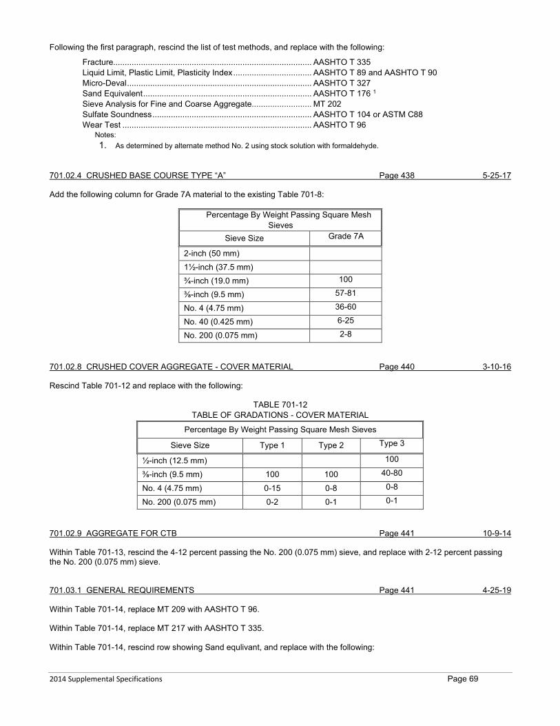
2014 Supplemental Specifications Page 69
Following the first paragraph, rescind the list of test methods, and replace with the following:
Fracture...................................................................................... AASHTO T 335 Liquid Limit, Plastic Limit, Plasticity Index .................................. AASHTO T 89 and AASHTO T 90 Micro-Deval ................................................................................ AASHTO T 327 Sand Equivalent ......................................................................... AASHTO T 176 1 Sieve Analysis for Fine and Coarse Aggregate.......................... MT 202 Sulfate Soundness ..................................................................... AASHTO T 104 or ASTM C88 Wear Test .................................................................................. AASHTO T 96
Notes: 1. As determined by alternate method No. 2 using stock solution with formaldehyde.
701.02.4 CRUSHED BASE COURSE TYPE “A” Page 438 5-25-17 Add the following column for Grade 7A material to the existing Table 701-8:
Percentage By Weight Passing Square Mesh Sieves
Sieve Size Grade 7A
2-inch (50 mm)
1½-inch (37.5 mm)
¾-inch (19.0 mm) 100
⅜-inch (9.5 mm) 57-81
No. 4 (4.75 mm) 36-60
No. 40 (0.425 mm) 6-25
No. 200 (0.075 mm) 2-8 701.02.8 CRUSHED COVER AGGREGATE - COVER MATERIAL Page 440 3-10-16 Rescind Table 701-12 and replace with the following:
TABLE 701-12 TABLE OF GRADATIONS - COVER MATERIAL
Percentage By Weight Passing Square Mesh Sieves
Sieve Size Type 1 Type 2 Type 3
½-inch (12.5 mm) 100
⅜-inch (9.5 mm) 100 100 40-80
No. 4 (4.75 mm) 0-15 0-8 0-8
No. 200 (0.075 mm) 0-2 0-1 0-1 701.02.9 AGGREGATE FOR CTB Page 441 10-9-14 Within Table 701-13, rescind the 4-12 percent passing the No. 200 (0.075 mm) sieve, and replace with 2-12 percent passing the No. 200 (0.075 mm) sieve. 701.03.1 GENERAL REQUIREMENTS Page 441 4-25-19 Within Table 701-14, replace MT 209 with AASHTO T 96. Within Table 701-14, replace MT 217 with AASHTO T 335. Within Table 701-14, rescind row showing Sand equlivant, and replace with the following:

2014 Supplemental Specifications Page 70
Sand equivalent (AASHTO T 176 3) 45% min. Rescind Note 3 and replace with the following:
3. As determined by alternate method No. 2 using stock solution with formaldehyde. RAP, RAS, and Hydrated Lime will be excluded from the JMF for Sand Equivalent testing purposes,
Rescind the second paragraph (that begins, “All aggreagte must…”) and replace with the following:
All aggregate must be non-plastic when tested in accordance with AASHTO T 89 and AASHTO T 90. 701.03.2 AGGREGATE FOR PLANT MIX SURFACING Page 443 5-25-17 Within Table 701-15, rescind the ≥13.5% minimum VMA for the ½-inch mix, and replace with ≥14.5% minimum VMA for the ½-inch mix. Within Table 701-15, rescind the 65-78 range VFA% for the 0.3 to10 million EASLs and ≥10 million EASLs ranges, and replace with 65-80 range VFA% for both the 0.3 to10 million EASLs and ≥10 million EASLs ranges. Within Table 701-15, rescind the ≥15.5% minimum VMA for the ⅜-inch mix, and replace with ≥15.0% minimum VMA for the ⅜-inch mix. Following Table 701-15, add the following Note 3, referenceing both the VFA% Range of the ≤0.3 million EASLs and the minimum VMA of the ⅜-inch max:
3. Mix Design value only. Meet the requirements of Table 701-18 during job mix production. Within Table 701-16, rescind the column titled “Job Mix Tolerance”. Rescind Table 701-17 and replace with the following:
TABLE 701-17 HAMBURG WHEEL TRACK REQUIREMENTS
PG Binder Grade Water Bath Temperature PG 58-XX 111 °F (44 °C) PG 64-XX 122 °F (50 °C) PG 70-XX 133 °F (56 °C)
Within Table 701-18, change the title of the column “Job Mix Tolerance” to “Job Mix Target Tolerance”. Within Table 701-18, rescind the rows showing VMA and D/A requirements for non-commercial mix and replace with the following:
VMA 13.0 to 17.0 14.5 to 18.0 15.5 to 18.4 ± 0.6 12.4 to 17.6 13.9 to 18.6 14.9 to 19.0 D/A 2 0.6 to 1.4 ±0.2 0.4 to 1.6
Within Table 701-18, rescind the rows showing VMA and D/A requirements for commercial mix and replace with the following:
VMA 12.4 to 17.6 13.9 to 18.6 14.9 to 19.0 N/A N/A D/A 0.4 to 1.6 N/A N/A
Following Table 701-18, rescind Note 3 and replace with the following:
3. Start-up job mix range only applies to production before initial target set. Job mix target tolerances do not apply to start up job mix range.
701.04.3 GRANULAR BEDDING MATERIAL Page 447 1-19-17 Rescind the first sentence and replace with the following: Furnish granular bedding material in accordance with either of the following:
1. Table 701-4 No.2; or

2014 Supplemental Specifications Page 71
2. ¾-inch material in accordance with Table 701-16, with a maximum of 10% passing the No. 4 sieve. 701.12 DIGOUT AND SUB-EX REPLACEMENT MATERIAL Page 449 12-8-16 Rescind Subsection 701.12 Digout and Sub-ex Replacement Material and replace with the following:
Furnish replacement material for digout and sub excavation areas consisting of a well-graded sand and gravel, free of organic and other deleterious material, meeting the AASHTO M 145 requirements for A-1-a group classification as amended by Table 701-24. Material in accordance with Subsection 701.02.4 may also be used as replacement material in either application. Any replacement material may consist of up to 50% RAP, uniformly blended. Crusher reject material may be used for either application provided it meets the requirements in Table 701-24.
TABLE 701-24 DIGOUT AND SUB EXCAVATION REPLACEMENT MATERIAL
Percentage By Weight Passing Square Mesh Sieves Sieve size Percent Passing
Digout 2-inch (50 mm) 100 No. 200 (0.075 mm) 8 maximum
Sub excavation 6-inch (152 mm) 100 No. 200 (0.075 mm) 8 maximum
Crusher Reject
2-inch (100 mm) 100 No. 4 (4.75 mm) 0-50 No. 40 (0.425 mm) 0-30 No. 200 (0.075 mm) 8 maximum
702.01 BITUMINOUS MATERIALS Page 451 5-25-17 Within the List of materials, rescind only the line for Polymer-Modified Cationic Emulsified Asphalt and replace with the following:
Polymer-Modified Cationic Emulsified Asphalt AASHTO M 316 702.02 TESTING AND ACCEPTANCE Page 451 5-25-17
Rescind Table 702-3. 704.01.1 SHEET ALUMINUM Page 465 10-9-14 Within Table 704-1, rescind the third heading “Maximum Back Brace Spacing Thickness” and replace with the following:
Maximum Back Brace Spacing 704.01.6 TREATED WOOD POSTS AND POLES Page 467 7-14-16 Within the second paragraph, rescind the sixth (last) sentence (than begins, “Full length pressure-treat…”) and replace with the following:
Full length pressure-treat all timber posts and poles in accordance with Subsection 706.04, regardless of length. 704.01.10(A) GENERAL Page 468 10-9-14 Remove the following Traffic Control Rate Schedule Group Numbers from Table 704-3:
18 (sign panel), 23, and 28. 704.02.1 ALUMINUM SIGNS Page 469 10-9-14 Within the second paragraph, rescind the third sentence (than begins, “Coat in accordance…”) and replace with the following:
2014 Supplemental Specifications Page 72
Coat in accordance with ASTM B921 or B449 Class 2, 10 to 35 milligrams thick per square foot (0.093 m2).
707.01 CONCRETE JOINT FILLERS Page 475 12-11-14 Rescind the heading only (707.01 CONCRETE JOINT FILLERS) and replace with the following:
707.01 JOINT FILLERS 707.01.1 CONCRETE PAVEMENTS Page 475 5-25-17 Rescind Subsection 707.01.1 and replace with the following:
707.01.1 Pavement A. Expansion Joint Filler. Furnish expansion joint filler Type II cork in accordance with AASHTO M 153. B. Joint Sealing Material. Furnish sealing material for all types of pavement joints that is a hot-poured thermoplastic
rubber or rubber asphalt compound in accordance with ASTM D6690 Type IV and having a resilience within the range from 30%-60%. Use ready-mixed, cold applied joint fillers for sealing concrete pavement joints only with the Project Manager’s prior written approval.
708.03 PERFORATED CONCRETE PIPE Page 477 3-10-16 Rescind Subsection 708.03 and replace with the following:
708.03 RESERVED 708.05 PVC GRAVITY SEWER AND DRAIN PIPE Page 477 4-16-15 Rescind Subsections 708.05, 708.05.1, 708.05.2 and 708.05.3 and replace with the following: 708.05 PVC GRAVITY PIPE
Furnish PVC pipe in accordance with ASTM D1784, and produced by a continuous extrusion process employing a prime grade of unplasticized polyvinyl chloride. Ensure the grade used is highly resistant to hydrogen sulfide, sulfuric acid, gasoline, oil, detergents and other chemicals found in sewage and industrial wastes. Furnish perforated pipe in accordance with ASTM D2729.
Ensure each pipe length is marked with nominal size, PVC cell classification, ASTM designation and SDR, if applicable. Ensure pipe has a minimum SDR of 35.
With the exception of Schedule 40 or 80 PVC conduit, ensure each pipe length has a bell providing a watertight joint when jointing the bell and spigot with a rubber ring. Make joint using a rubber gasket compressed between the outer surface of the spigot and the inner surface of the bell. Ensure the joint is completely sealed by the gasket, providing a watertight joint under all service conditions, including expansion, contraction, settlement and pipe deformation. Assemble the rubber ring joint according to manufacturer recommendation. 708.05.1 Schedule 40 or 80 PVC Conduit
For non-electrical conduit, furnish schedule 40 or 80 PVC pipe. 708.05.2 PSM PVC Pipe
Furnish PSM PVC pipe 4-inch through 15-inch nominal diameter gravity pipe in accordance with ASTM D3034. 708.05.3 Large diameter PVC Pipe
Furnish large diameter PVC pipe 18-inch through 48-inch in accordance with ASTM F679. 708.05.4 Profile Wall PVC
Furnish corrugated exterior with smooth wall interior profile wall PVC gravity pipe 4-inch through 36-inch (100 - 900 mm) nominal diameter in accordance with ASTM F949. 708.06 PVC PRESSURE WATER PIPE Page 478 4-16-15 Rescind Subsections 708.06, 708.06.1 and 708.06.2 and replace with the following: 708.06 PVC PRESSURE PIPE

2014 Supplemental Specifications Page 73
708.06.1 Pressurized Water Pipe
Furnish pressure PVC water pipe 4-inch through 12-inch (100 mm - 300 mm) nominal diameter in accordance with AWWA Specification C-900.
Furnish pressure PVC pipe 14-inch through 48-inch (350 mm-1200 mm) nominal diameter in accordance with AWWA Specification C-905.
Use DR 25 Class 165 pipe. Ensure pipe joints are bell and spigot and include an elastomeric gasket. Pipe sections must be marked with diameter, code designation, DR, pressure class, and AWWA specification. 708.06.2 Pressurized Sewer Pipe
Furnish pressure PVC sewer pipe in accordance with ASTM D2241. 710.03 POWDER COATING PREQUIALIFICATION AND CERTIFICATION Page 487 2-26-15 Within Table 710-7, replace the ASTM Designation for testing Thickness with D7091. 711.01.1 BAR REINFORCING Page 489 7-14-16 Rescind the second (last) paragraph (than begins, “The Project Manager…”) and replace with the following:
Furnish bar reinforcing from a source audited by the NTPEP Reinforcing Steel/Welded Wire Reinforcement Audit Program and listed on the QPL. 711.01.3 WIRE AND WIRE MESH Page 489 7-14-16 Rescind the third (last) paragraph (than begins, “Furnish bar mats …”) and replace with the following:
Furnish bar mats in accordance with AASHTO M 54. Furnish wire, wire mesh, and bar mats from a source audited by the NTPEP Reinforcing Steel/Welded Wire Reinforcement Audit Program and listed on the QPL. 711.06 HIGH TENSILE STRENGTH BOLTS Page 489 1-18-18 Rescind the first paragraph (than begins, “Furnish high strength…”) and replace with the following:
Furnish high strength bolts for structural steel joints in accordance with ASTM F3125 Grades A325 (Type 1 or 3), or A490 (Type 1 or 3) as specified in the contract. Rescind Part (A) and replace with the following:
A. Tension Control Bolts. Meet the requirements of ASTM F3125 Grade F1852 when substituting tension control bolt assemblies for Grade A325 bolts. Meet the requirements of ASTM F3125 Grade F2280 when substituting tension control bolt assemblies for Grade A490 bolts.
Within Part (B), rescind Table 711-1 and replace with the following:
TABLE 711-1 HEAVY HEX NUTS
Bolt Type Heavy Hex Nut ASTM A563
Grade A325 Type 1-plain Grade C, C3, D, DH, DH3 Type 1-galvanized DH Type 3 Grade C3, DH3
Grade A490 Type 1 Grade DH, DH3 Type 3 Grade DH3
Notes: 1. Plain heavy hex nuts Grades C, C3 and D must have a minimum hardness of 89 HRB. 2. A194 Grade 2H may be substituted for A563 Grade DH 3. When galvanized fasteners are specified, furnish assemblies manufactured and lubricated with a visible dye, so a visual check verifies the lubricant’s presence at installation.
Within Part (C), rescind the forst sentence (that begins, “Furnish washers…”) and replace with the following:
2014 Supplemental Specifications Page 74
Furnish washers bolts in accordance with ASTM F436.
Rescind Part (E) and replace with the following:
E. Galvanized High Strength Bolts. Hot dip galvanize Grade A325 bolts and hardware in accordance with ASTM F2329. Hot dip galvanizing Grade A490 bolts is not allowed.
711.12.3 DRAINAGE STRUCTURE CASTINGS Page 491 8-10-17 Rescind the first (only) paragraph (than begins, “Furnish structural drainage…”) and replace with the following:
Furnish structural drainage castings in accordance with the Detailed Drawings and AASHTO M 306 - HS-20. 711.19 METRIC PLATE SUBSTITUTION Page 493 10-9-14 Rescind the first sentence of the first paragraph (than begins, “Define the requirements…”) and replace with the following:
Substituting standard inch-sized steel plate for metric steel plate is allowed. 713.01 WATER Page 499 5-25-17 Rescind the first paragraph (than begins, “Furnish water for…”) and replace with the following:
Furnish water for mixing and curing in accordance with AASHTO M 157, 4.1.4. Known potable water may be used without testing. 713.03 CHLORIDES Page 499 7-14-16 Within Part (A), rescind the second sentence (than begins, “Products will be…”) and replace with the following:
Products will be tested as received in accordance with MT 502. Within Part (B), rescind the second sentence (than begins, “Products will be…”) and replace with the following:
1. Products will be tested as received in accordance with MT 502. 713.05 TOPSOIL Page 501 3-10-16 Rescind Parts 1, 2 and 3 following the second paragraph (that begins, “Meet the following…”) and replace with the following:
1. Soil pH between 5.5 and 8.0 or up to 8.5 if the exchangeable sodium is less than 10%; 2. Soil electrical conductivity less than 4.0 dS/m or up to 4.5 dS/m if the exchangeable sodium is less than 10%; and 3. Organic content between 2% and 10%. When landscape grade topsoil is specified, ensure organic content is
between 5% and 10%. Rescind the third (last) paragraph (that begins, “Topsoil is sampled…”) and replace with the following:
Topsoil is sampled and tested in accordance with MT 601. 713.06 RESERVED Page 501 10-9-14 Rescind Subsection 713.06 and replace with the following: 713.06 WEED CONTROL MAT
Furnish a machine woven weed control mat composed of synthetic polypropylene or polyolefin fibers. Meet the requirements in Table 713-9.

2014 Supplemental Specifications Page 75
TABLE 713-9 WEED CONTROL MAT
Property Value Test Method Average weight minimum 4 oz/yd2 ASTM D3776 Water permeability 10-15 gallons per min per square foot ASTM D4491 UV stability (minimum % tensile retention) 70% ASTM D4355
(2,500-hour exposure)
Grab tensile strength Warp:90 lbs minimum Fill: 50 lbs minimum ASTM D4632
713.12 ROLLED EROSION CONTROL PRODUCTS Page 503 1-18-18 Rescind Subsection 713.12 and replace with the following: 713.12 Rolled Erosion Control Products
Furnish rolled erosion control products listed on the Department’s QPL, as specified in the contract and meeting the requirements of this Subsection. If required, furnish natural fiber netting or stitching consisting of woven 100% biodegradable natural fibers such as coir, jute or sisal. Furnish blankets designed to stabilize and hold previously applied mulch or compost on slopes as well as newly constructed stream banks and slopes.
Natural fiber netting is available in various fiber types, strengths, weights and mesh-opening sizes. A. Erosion Control Blankets. Furnish 100% biodegradable products for all types.
1. Short Term Blanket. An erosion control blanket composed of 100% straw or 100% excelsior. 2. Long Term Blanket. An erosion control blanket composed of 70% straw and 30% coconut or 100% excelsior. 3. High Performance Blanket. An erosion control blanket composed of 100% coconut or 100% excelsior.
B. Permanent Turf Reinforcement Mat. 1. Synthetic Fiber Matrix. Furnish a web of mechanically bonded synthetic fibers that are entangled to form a strong
and dimensionally stable mat. Place fibers between 2 or 3 high-strength, biaxially oriented nets mechanically bound together by stitching with polyolefin thread. The netting material must be resistant to biological, chemical, and ultra-violet degradation.
2. Natural Fiber Matrix. Furnish a natural fiber matrix constructed of two or three nets of heavy-duty polypropylene, polyethylene or nylon. The internal matrix fiber is composed of a natural fiber such as curled wood, straw or coconut.
TABLE 713-4
ROLLED EROSION CONTROL
Type Mass1
(lbs/yd)
Tensile Strength – MD2
(lbs/ft)
Min. Shear Strength
(lbs/ft2) Short term 0.5 120 1.70 3 Long term 0.5 150 2.0 3
High performance 0.6 190 2.25 3 TRM – natural fiber
matrix 0.8 500 10.0 4
TRM – synthetic fiber matrix 0.5 300 12.0 4
Notes: 1. Combined fiber matrix and netting 2. Machine direct 3. Minimum shear stress the rolled erosion control product (un-vegetated) can sustain without physical damage or
excess erosion (>1⁄2-inch soil loss) during a 30-minute flow event in accordance with ASTM D6460 or D7207. 4. Minimum shear stress the TRM (fully vegetated) can sustain without physical damage or excess erosion (>1⁄2-inch
soil loss) during a 30-minute flow event in accordance with ASTM D6460 or D7207. 713.13 COMPOST Page 504 10-9-14 Rescind the second paragraph (that begins, “Furnish compost in…”) and replace with the following:
Furnish compost listed on the QPL and in accordance with Table 713-8. 714.03 TEMPORARY WATERBORNE TRAFFIC PAINT Page 507 7-14-16 Within Table 714-1, rescind the reference to MT 544 and replace with MT 548.
2014 Supplemental Specifications Page 76
714.04 WATERBORNE TRAFFIC PAINT Page 507 7-14-16 Add the following sentence to the end of the first (only) paragraph:
Blue, red or black paint may be used without being NTPEP tested if the base paint is the same chemical composition as a NTPEP tested paint. Within Table 714-2, rescind the references to MT 543, MT 544, MT 545 and MT 549 and replace all with MT 548. Below Table 714-2, add the following note referring to the “Color” section of Table 714-2:
Note 1: Furnish black paint in accordance with color chip 37038 of Federal Standard 595B. 714.05 HIGH DURABILITY WATERBORNE TRAFFIC PAINT Page 508 7-14-16 Add the following sentence to the end of the first (only) paragraph:
Blue, red or black paint may be used without being NTPEP tested if the base paint is the same chemical composition as a NTPEP tested paint. Within Table 714-3, rescind the references to MT 543, MT 544, MT 545 and MT 549 and replace all with MT 548. Below Table 714-3, add the following note referring to the “Color” section of Table 714-3:
Note 1: Furnish black paint in accordance with color chip 37038 of Federal Standard 595B. 714.06 EPOXY OR OTHER POLYMERIC TRAFFIC PAINT Page 509 7-14-16 Add the following sentence to the end of the first (only) paragraph:
Blue, red or black paint may be used without being NTPEP tested if the base paint is the same chemical composition as a NTPEP tested paint. Within Table 714-4, rescind the references to MT 543 and MT 544 and replace both with MT 548. Below Table 714-4, add the following note referring to the “Color” section of Table 714-4:
Note 1: Furnish black paint in accordance with color chip 37038 of Federal Standard 595B. 714.08 REFLECTIVE GLASS BEADS Page 512 4-16-15 Rescind Subsection 714.08 and replace with the following: 714.08 REFLECTIVE GLASS BEADS
Furnish glass beads for reflectorizing traffic pavement markings in accordance with AASHTO M 247. Gradation and roundness will be determined in accordance with AASHTO PP 74. In the event of a dispute, ASTM D1274 will be used for gradation determination and ASTM D1155 will be used for roundness determination. 717.01.3 LIQUID MEMBRANE-FORMING CONCRETE CURING COMPOUNDS Page 519 9-20-18 Rescind Subsection 717.01.3 and replace with the following: 717.01.3 Liquid Membrane-Forming Concrete Curing Compounds
Furnish liquid membrane-forming compounds for curing concrete listed on the QPL and in accordance with ASTM C 309 Type 1-D, clear or translucent and containing a fugitive dye, or Type 2, white pigmented. 717.01.4 CONCRETE CURE AND SEAL COMPOUNDS Page 519 9-20-18 Add the following Subsection:

2014 Supplemental Specifications Page 77
717.01.4 Concrete Cure and Seal Compounds
Furnish liquid cure and seal compounds for concrete listed on the QPL in accordance with ASTM C1315 Type 1, Class A. Furnish clear products. 717.01.5 WHITE POLYETHYLENE SHEETING Page 519 *11-14-19 Add the following Subsection: 717.01.5 White Polyethylene Sheeting
Furnish white, reflective, polyethylene sheeting material for curing concrete in accordance with ASTM C171. 717.02.2(C) DECK SEALANT SAND Page 519 10-9-14 Rescind Subsection 717.02.2(C) and replace with the following:
C. Deck Sealant Sand. Furnish sand for bridge deck crack sealing operations in accordance with manufacturer’s recommendations.