Embed Size (px)
Citation preview
Supplemental Restraint System(sRstGomponent Location Index .................. 23-266Description ..23-267Circuit Diagram 23-268Wiring Locations 23-270Precautions/Procedures ..23-271Troubfeshooting ............. ..23-276Airbag Assembly
Repfacement .................. 23-295Disposal ....23-299
Cable ReelReplacement .................. 23-301
Dash SensorReplacement .................. 23-305
SRS UnitReplacement .................. 23-307
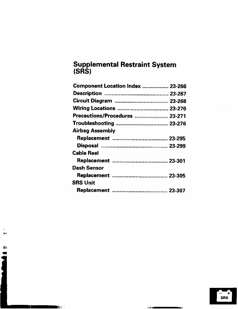
Supplemental Restraint System (SRS)Component Locirtion Index
UNDER.DASHFUSE/RELAY BOX
SRS INDICATOR LIGHT(ln th6 gaug6 assembly)Troubleshooting, page 23-276Gauge assembly, page 23-113
CABLE REELReplacement,page 23-301
AIRBAGBeplacement, page 23.295
SRS UNIT (lncluding cowl sensorl
SRS MAIN HARNESS-FRONT PASSENGER'S AIREAGBRANCH lExc€pt Caned. RS modol)
To CRUISE CONTROLSET/RESUME SWITCH
RIGHT DASH SENSORReplacement, page 23-305
FRONT PASSENGER'SAIRBAGlExcept Canads RS model)Replacement, page 23-295Disposal, page 23'299
LEFT DASH SENSORReplacement, page 23-305
23-266
Replacement, page 23-307
SRS INOICATOR CIRCUIT{ln th€ glug€ sssombv}
UNOER_HOOD DRIVER'SFUSE/ AIRBAGRELAY INFLATOR80x
SAOC
BUC
GNOrDc
MI
r - - - -r nr t li l l
SADH-
-
oaa@oaa@a@a@@@aa
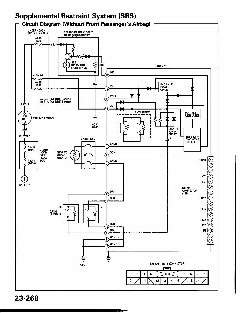
Supplemental Restraint System (SRSICircuit Diagram (Without Front Passenger's Airbagl
23-268
SRS INOICATOF CIRCUITlln lh6 grugo .$.mblyl
IIII nI l lI t lt UI
SADH
o@o@@aa@a@a@@@aa
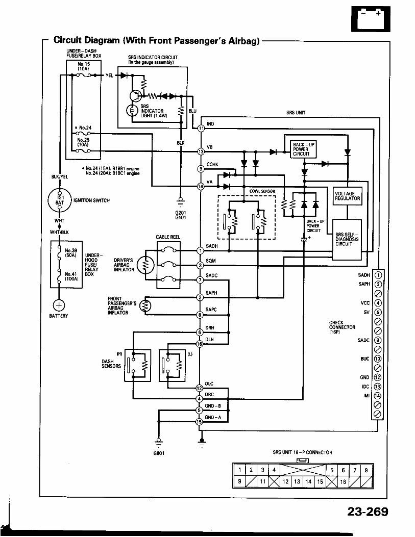
Gircuit Diagram (With Front Passenger's AirbaglUNOE8- DASHFUSSRELAY BOX
DRIVER'SAIREAGINFI.A]OR
FROI.ITPASSENGER'SAIREAGINFLATOR
UNDERHOODFUSE/REI.AY80x
SRS UNIT l8-P COI'INECTOR
23-269
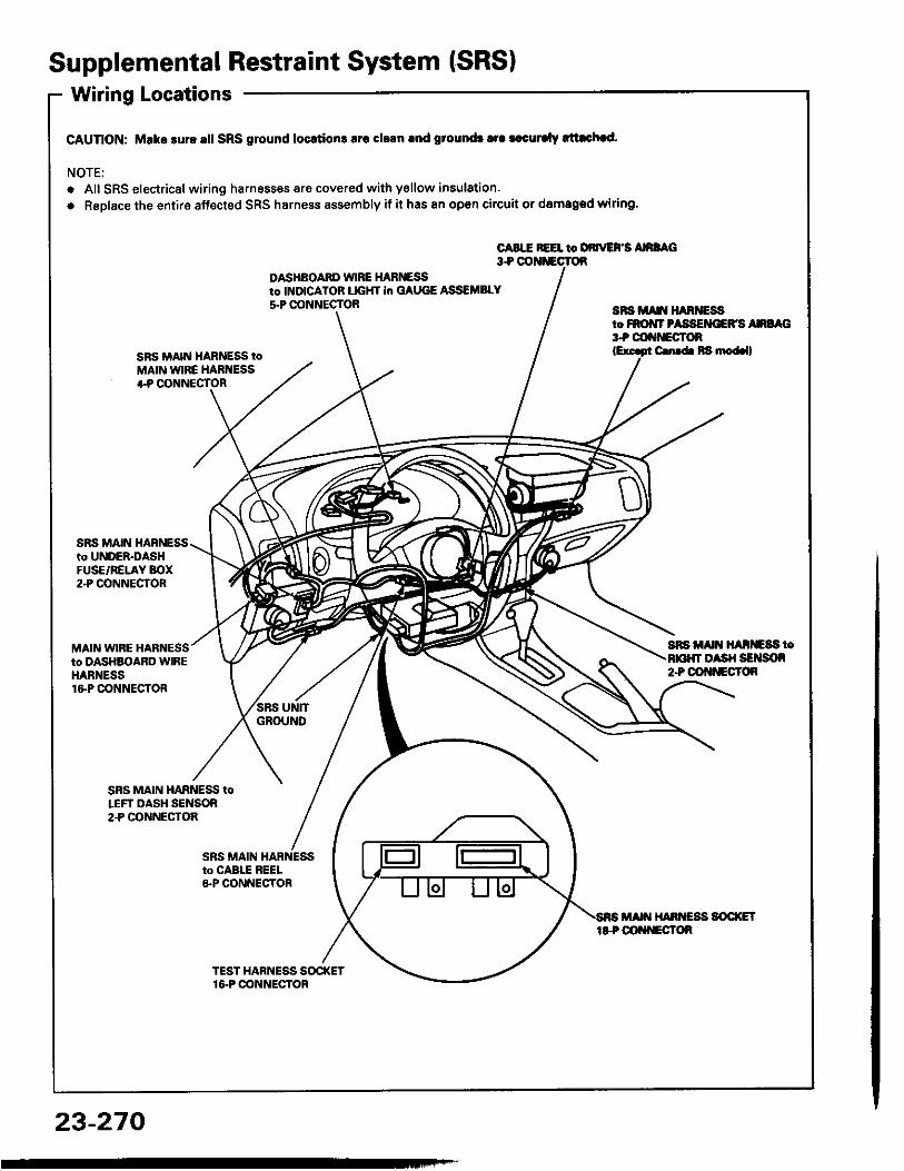
Supplemental Restraint System (SRSIWiring Locations
CAUnON: Make sure all SRS ground locrtion3 lrc clrln rnd ground3 tra |.curalv rltachad.
NOTE:o Alt SRS electricsl wiring harnesses are covered with ysllow insulation.. RsDlace the entire affected SRS harness assembly if it has an open circuit or damaged wiring.
CABIE REEL to DdrrEFS AnaAC3+ OOI{iECTOR
DASHBOARD WIRE HARNEi9to INDICATOB UGHT in GAUGE ASSEMBLY5-P CONNECTOB aFs irA[t H^RiEss
to FROiIT PASSEMIEFS Ana G3t coftf'Eclon
SRS MAIN HARNESS tOMAIN WIRE HARNESS+P OONNECTOR
C. b Ra nod.ll
SnS Alt{ ll^ntc8s too sH SErson
2+ OOt{tlEcT()R
SRS MAIN HARNESSto UNDER-DASHFUSE/RELAY BOX2"P @NNECTOR
MAIN WIRE HARNESSto DASHBOARD WIREHARNESSlGP CONNECTOR
SBS MAIN HARNESS toLEFT DASH SENSOR2.P CONNECTOA
23-270
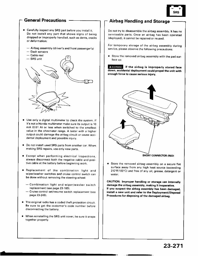
- Dash sensors- Cable reel- SRS un i t
General Precautions
Carefully inspect any SRS part before you install i t.Do no t ins ta l l any par t tha t shows s igns o f be ingdropped or improperly handled, such as dents, cracksor deformation:
- Airbag assembly {driver's and front passenger's)
Airbag Handling and Storage
Do not try to disassemble the airbag assembly. lt has noserviceable parts. Once an airbag has been operated(deployed), it cannot be repaired or reuseo.
For temporary s to rage o f the a i rbag assembly dur ingservice, please observe the following precautions:
. Store the removed airbag assembly with the pad sur-face up.
!@ It the airbag is impropsrty stored facsdown, accidental deployment could propel the unit withenough force to cause setious iniury
Store the removed airbag assembly on a secure flatsufface away from any high heat source (exceeding212"Fl1OO'Cl and free of any oil. grease, detergent or
CAUTION: lmproper handling or storage can internallydamage the airbag assembly, making it inoperativ€.ll you suspect the airbag assembly has been damagod,install a new unit and rgler to the Deployment/DigposalProcedures lor disposing of the dsmaged airbag.
Use only a digital multimeter to check the system. lfi t 's not a Honda multimeter make sure its output is 10mA (0.01 A) or less when switched to the smallestvalue in the ohmmeter range. A tester with a higheroutput could damage the airbag circuit or cause accidental deployment and possible injury.
Do not install used SRS parts from another car. Whenmaking SRS repai.s, use only new pans.
E x c e p t w h e n p e r f o r m i n g e l e c t r i c a l i n s p e c t i o n s ,always disconnect both the negative cable and posi-tive cable at the battery before beginning work.
R e p l a c e m e n t o f t h e c o m b i n a t i o n l i g h t a n dwiper/washer switches and cruise control switch canbe done without removing the steering wheell
- C o m b i n a t i o n l i g h t a n d w i p e r / w a s h e r s w i t c hreplacement (see page 23-160).
- Cruise control sevresume switch replacement {seepage 23-2491 .
The original radio has a coded theft protection circuit.Be sure to get the customer's code number beforedisconnecting the battery.
When reinstall ing the SRS unit cover, be sure it snapstogether properly.
SHORT CONNECTON {REDI
23-271
Supplemental Restraint System (SRSIWiring Precautions
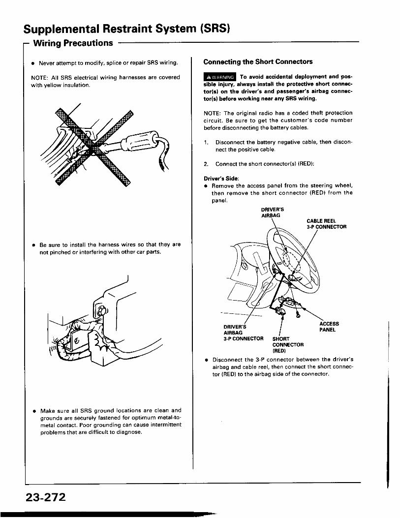
o Never attempt to modify. splice or repair SRS wiring.
NOTE: All SRS electrical wiring harnesses are coveredwith yellow insulation.
Be sure to install the harness wires so that they arenot pinched or interfering with other car pans.
Make sure a l l SRS ground loca t ions are c lean andgrounds are securely fastened for optimum metal-to-metal contact. Poor grounding can cause intermittentproblems that are diff icult to diagnose.
23-272
Connecting the Short Connectors
@ To avoid accident8l deploymont and pos-5ibl6 iniury, slways insiall the protectiva short connec-tor(s) on tho drivgr'3 and passengor's airbag connec.tor(s) be{ore working noar any SRS wiring.
NOTE: The original radio has I coded theft protectionc i rcu i t . Be sure to ge t the cus tomer 's code numberbefore disconnecting the battery cables.
1. Disconnect the battery negative cable. then discon-nect the Dositive cable.
2. Connect the short connector(s) {RED):
Driver's Side:. Remove the access panel from the steering wheel.
then remove the shor t connector (RED) f rom theDaner.
DRIVER'SAIRBAG
CONNECTORIREDI
Disconnect the 3-P connector between the driver'sairbag and cable reel, then connect the short connec-tor {RED} to the airbag side oi the connector.
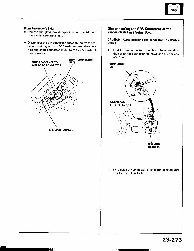
Front Pas3enger's Side:. Remove the glove box damper (see section 20), and
then remove the glove box.
. Disconnect the 3-P connector between the front oas-senger's airbag and the SRS main harness, then con-nect the short connector (RED) to the airbag side ofthe connector.
SHORT CONNECTOR(REDI
SRS MAIN HARNESS
b,
Disconnecting the SRS Connector at theUnder-dash Fuse/relay Box:
CAUTION: Avoid br.aking the connoctor; it's doubte-locksd.
1. First l i ft the connector l id with a thin screwdriver,then press the connector tab down and pull the con-neclor out.
CONNECTORt_tD
To reinstall the connector. push it into position unti li t cl icks, then close its l id.
23-273
Supplemental Restraint System (SRS)Steerin g-related Precautions
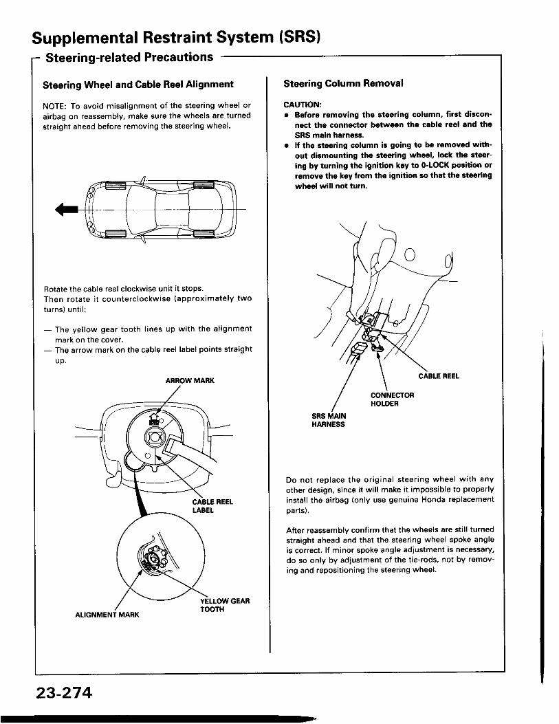
Steering Wheel and Cable Reel Alignment
NOTE: To avoid misalignment of the steering wheel orairbag on reassembly, make sure the wheels are turnedstraight ahead before removing the steering wheel.
Rotate the cable reel clockwise unit it stops.Then ro ta te i t co u n te rc lockwise (approx imate ly twoturns l un t i l :
- The ye l low gear too th l ines up w i th the a l ignmentmark on the cover.
- The arrow mark on the cable reel label points straightup .
ALIGNMENT MARK
ARROW MARK
23-274
Steering Column Removal
CAUTION:. Bofore romoving tho 3l6oring column, first discon'
nect tha connector between ths cablo 16ol snd thoSRS main harness.
. lf th6 stssring column is going to be removed with-out dbmounting the stesring wh6el, lock the sl6sr-ing by turning th€ ignition k.y to o-LOCK po3ition orremovo tha k€y llom ths ignilion so that th6 3loaringwheel will not turn.
Do no t rep lace the or ig ina l s teer ing whee i w i th anyother design, since it wil l make it impossible to properlyinstsll the airbag (only use genuine Honda replacementoans).
After reassemblv confirm that the wheels are sti l l turnedstraight ahead and that the steering wheel spoke angleis correct, lf minor spoke angle adjustment is necessary,do so only by adjustment of the tie-rods, not by remov-ing and repositioning the steering wheel.
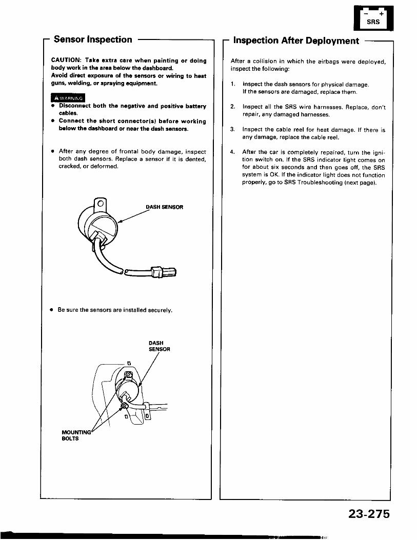
Sensor Inspection
CAUTION: Tak€ €xtra care whon painting or doingbody work in the ar€a bslow th6 dalhboard.Avoid dirost exposure ot lh6 sonsors or wiring to hestguns, wolding, or spraying equipmont.
Di3connact both the nogativo and po3itivo b!fterycable3.Connsct tho short conneclor(s) before workingbslow the da3hboard or nsar lhe dash sen3o.3.
After any degree of frontal body damage, inspectboth dash sensors. Replace a sensor if i t is dented,cracked, or deformed.
DASH SENSOR
a Be sure the sensors are installed securelv,
Inspection After Deployment
After a coll ision in which the airbags were deployed.inspect the following:
1. Inspect the dash sensors for physical damage.lf the sensors are damaged, replace them.
2. Inspect all the SRS wire harnesses, ReDlace, don'trepair, any damaged harnesses.
3. Inspect the cable reel for heat damage. lf there isany damage. replace the cable reel.
4. After the car is completely repaired. turn the igni-tion switch on. lf the SRS indicator l ight comes onfor about six seconds and then goes off, the SRSsystem is OK. lf the indicator l ight does not functionproperly, go to SRS Troubleshooting (next page).
BOLTS
23-275
Supplemental Restraint System (SRSITroubleshooting
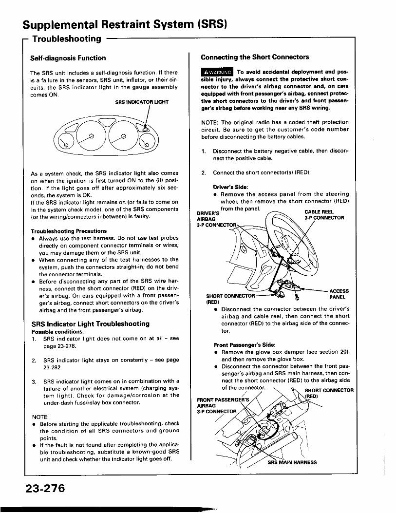
Self-diagnosis Function
The SRS unit includes a self-diagnosis function. lf thereis a failure in the sensors. SRS unit, inflator, or their cir-cu i ts , the SRS ind ica tor l igh t in the gauge sssemblycomes ON.
As a system check, the SRS indicator l ight also comeson when the ignition is f irst turned ON to the (l l) posi-tion. lf the l ight goes off after approximately six sec-onds, the system is OK.lf the SRS indicator l ighr remains on (or fails to come onin the system check mode), one of the SRS components(or the wiring/connectors inbetween) is laulty
Troubleshooting Precautionsa Always use the test harness. Do not use test probes
directly on component connector terminals or wires;you may damage them or the SRS unit.
a When connecting any of the test harnesses to thesystem, push the connectors straight-in; do not bendthe connector terminals,
. Before disconnecting any part of the SRS wire har-ness, connect the shon connector (RED) on the driv-er's airbag. On cars equipped with a front passen-ger's airbag, connect short connectors on the driver'sairbag and the front passenger's airbag.
SRS Indicator Light TroubleshootingPossiblo conditions:1. SRS indicator l ight does not come on at all - see
page 23-278.
2. SRS indicator l ight stays on constantly - see page23-242.
3. SRS indicator l ight comes on in combination with afailure of another electrical system (charging sys-tem l igh t ) . Check fo r damage/cor ros ion a t theunder-dash tuse/relay box connector.
NOTE:. Before starting the applicable troubleshooting. check
t h e c o n d i t i o n o f a l l S R S c o n n e c t o r s a n d g r o u n dpoints.
. lf the fault is not found after completing the applica-ble troubleshooting, substitute a known-good SRSunit and check whether the indicator l ight goes off.
23-276
MAIN HARNESS
Connecting the Short Connectors
@ To avoid.ccidental doploymont and pos.siblo iniury. alway3 connect ths protoctive short con.noctor to tha driver's airbag connectot and, on caf!equippod with front passongor's airbag, conncqt Prolac-tivs ghort connoctors to the d.ivsr's and tront passsn-gar's airbag before working nsai any SRS wiring.
NOTE: The original radio has a coded theft protectionc i rcu i t . Be sure to ge t the cus tomer 's code numberbefore disconnecting the battery cables,
Disconnect the battery negative cable, then discon-nect the oositive cable.
Connect the short connector(s) (RED):
Drivsr's Sido:. Romove the accoss pane l t rom the s teer ing
wheel, then remove the shon connector (BED)
1 .
2 .
from the panel.DRIVER'SAIRBAG
CABLE R€EL
3-P
ACCESSPANELSHONT CONNESTOR
(REDI. Disconnect the connector between the driver's
a i rbag and cab le ree l , then connect the shor tconnector {RED} to the airbag side of the connec-tor.
Front Pas€ngo/s Sido:. Remove the glove box damper (see section 20),
and then remove the glove box.. Disconnect the connector between the front pas-
senger's airbag and SRS main harness, then con-nect the short connector (RED) to the airbag sideof the connector, SHORT CONNECTOR
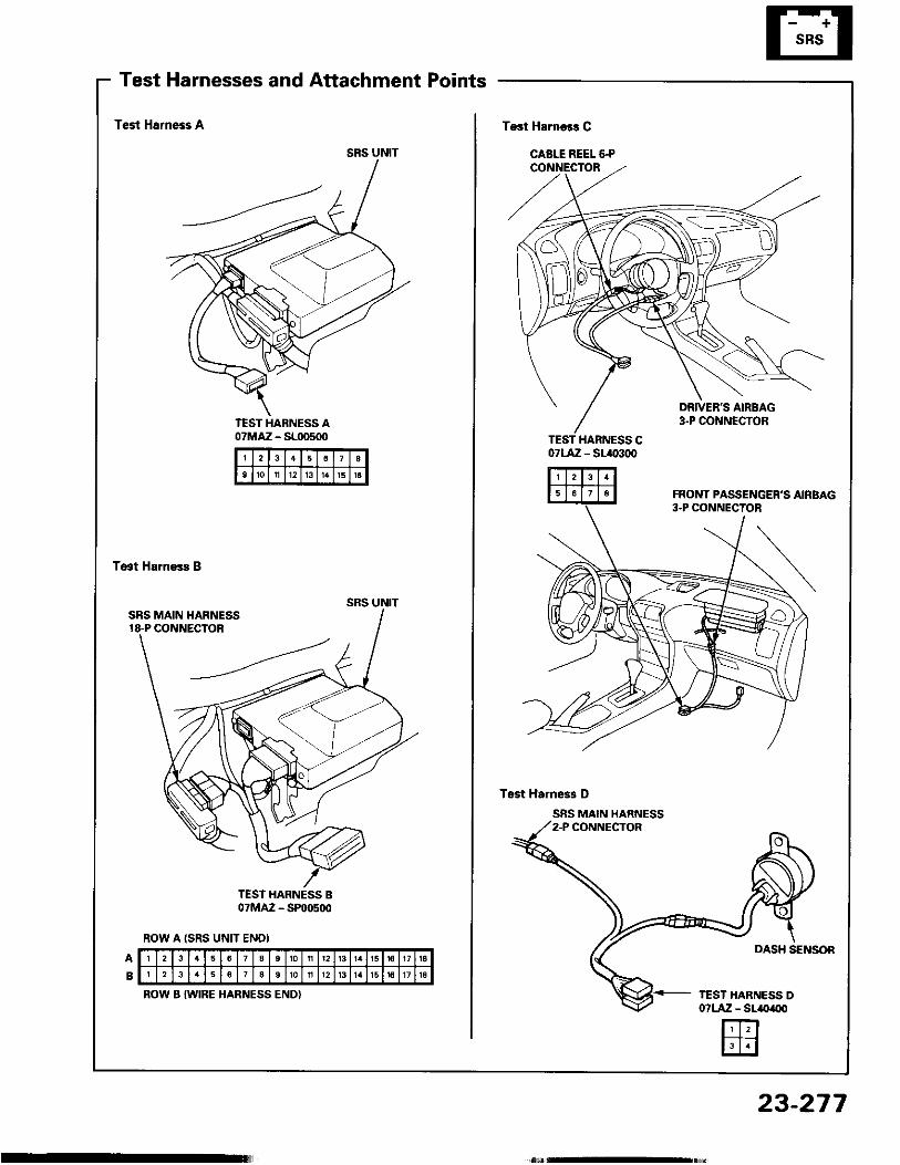
Test Harnesses and Attachment Points
SRS UNIT
Test Hsrness A
TEST HARNESS A07MAZ - SL|D500 TEST HARNESS C
07LA:Z - SL.()3(X'
Tast Harness B
TEST HARNESS B07MAZ - SP@500
ROW A ISRS UNfT ENDI
2 3 8to n 12 l3 1 6 16
2 13 1 5 16 17 | lI 2 12 1 5 l6 17 1A
ROW B IWIRE HARNESS END)
23-277
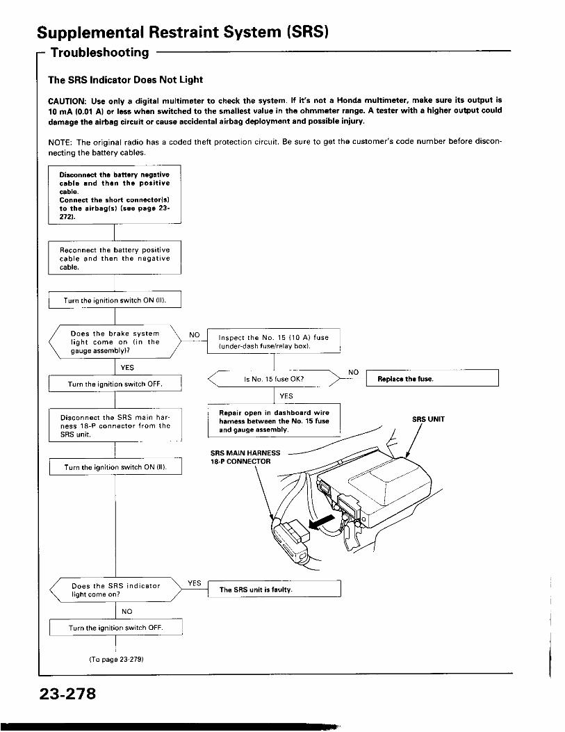
Supplemental Restraint System (SRS)Troubleshooting
The SRS Indicator Does Not Light
CAUTION: Uss only a digital multimeter to check the system. lf it's not a Honda multimeter, make sure its output is10 mA {0.01 Al or less when switched to the smallest value in the ohmmeter rang€. A tester with a highor ouiput coulddamage the airbag circuit or cause accidental airbag deployment and possible iniury
NOTE: The original radio has a coded theft protection circuit. Be sure to get the customer's code number before discon-necting the battery cables.
Dilconn6ct the battory negaiivecab le rnd t hon t ho pos i t i vecable.Connest the short connectorlslto tho airbaglsl (seo p6ge 23-272t.
R€connect the batterY Posit ivec a b l e a n d t h e n t h e n e g a t i v ecable.
Turn the ignit ion switch ON (l l ) .
Does t he b rake sys teml i g h t c o m e o n ( i n t h egauge assembly)?
Inspec t t he No . l 5 110 A ) f use(under-dash tuse/relay box).
ls No. 15 fuse OK?Turn the ignit ion switch OFF.
Repair open in dashboard wir6harness between the No. 15 tus€and gauge a3sombly.
D i sconnec t t he SRS ma in ha r -ness l 8 -P connec to r f r om theSRS unit.
Turn the ignit ion switch ON (l l ) .
D o e s t h e S R S i n d i c a t o rl ight come on? The SRS unit is faully.
Turn the igni t ion swi tch OFF.
SRS UNIT
SRS MAIN HARNESS18.P CONNECTOR
Io page 23'2791
23-274
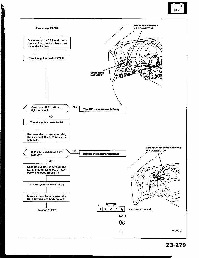
SRS MAIN HABNESS(From plgr 23.27E1
DASHBOARD WIFE HARNESS5-P CONNECTOR
8tU{ +
@I:
Disconnoct tho SRS m.in h6,-ng88 { -P conn6c lo r f , om thomrin wiao harn6$.
Tum lhq ignition switch ON (lll.
Doo3 tho SRS i nd i c . t o rlight com6 on? Th. SRS rnlin h..n... i.t ulty.
Tu.n tho ignition switch OFF.
Romovo tho g !u0c ! ss .mb lyth6n inrpoct ths SBS indicatorlight bulb.
Raplaca lh. indlc.toi llOht birlb.
Connoct ! voltmotoa bdwoln thrNo. 5 lormin.l (+) of tho 5-P con-noctor rnd body ground (-).
Turn the ignition switch ON (ll).
Moaauro tha voltrgo bolwcon thaNo. 5 termin.land body g.ound.
MAIN VNREHARNESS
(To p.go 2+280)
23-279
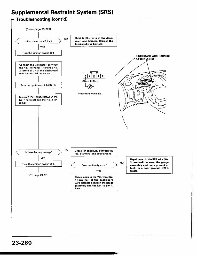
(From page 23-279)
Short in 8LU wire ol the da.h-borrd wi.o halno3s. Roplaca thad.3hbosrd wiro ha.no$.
ls there lesslhan 8.5 V ?
Turn the ignit ion switch OFF
Connect tho voltmeter betweenthe No. 1 terminal (+) and the No.3 terminal (-) of the dashbo€rdwire harness 5-P connector.
Turn the ignit ion switch ON (l l ) .
Measure the voltage between theNo. 1 terminal and th€ No.3 ter-mrna l ,
Ch6ck for continuity between th6No. 3 terminal and body ground.ls there battery vohage?
R.prir opcn in tho BLK wir. (No.3 tarmin!l) batwaan th. glugaaraambly and body ground otlook tor. poor ground 1G201,cilol I.
Turn the ignit ion switch OFF.
Rcprir open in th. YEL wi.o lNo.t t 6 rm ina l l o f t he d .3hbo . rdwir6 hamer! batwaen tho gtugor3s6mblv rnd tho No. 15 ll0 Alfu36.
SupplementalTroubleshooting(cont'd)
{To page 23-281}
RestraintSystem (SRSI
DASHBOARD WIRE HARNESS
View lrom wire side.
YELI+, BLK{-I
23-280
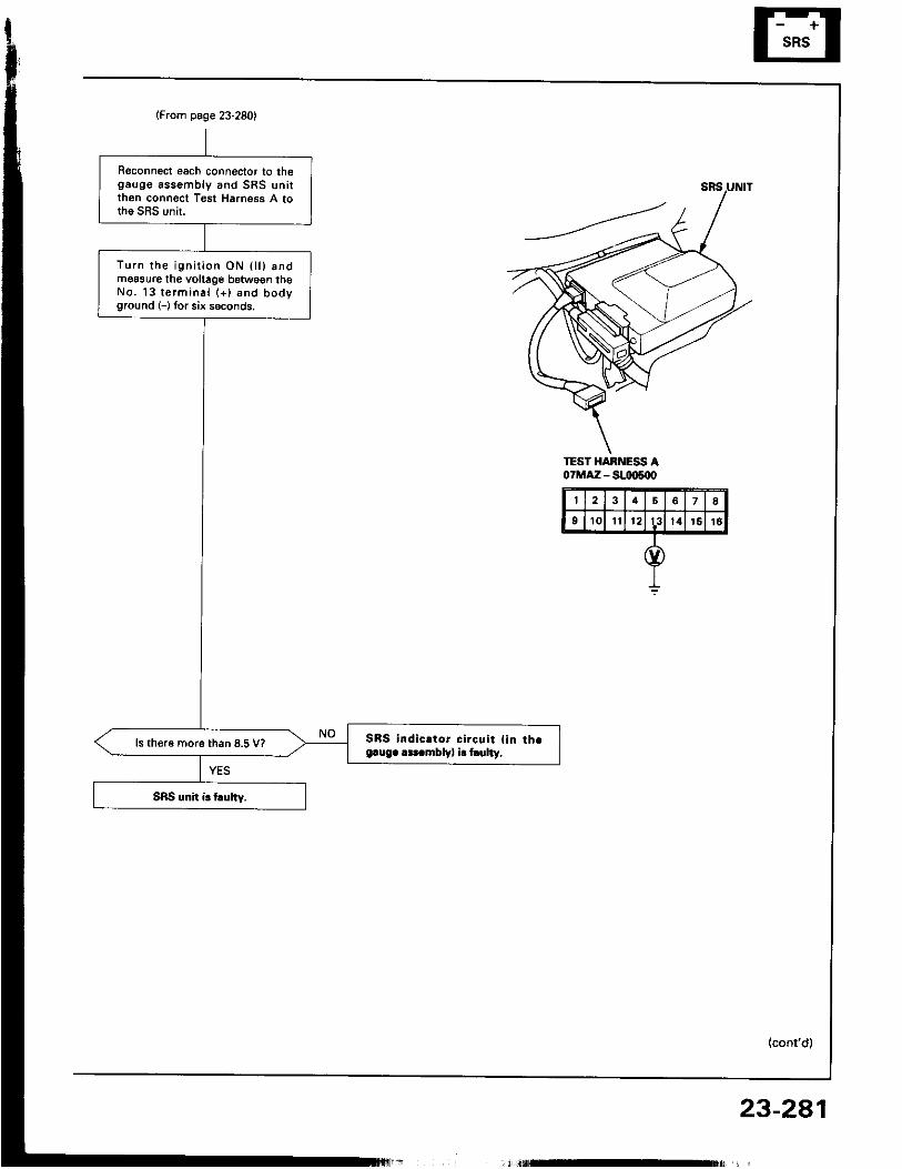
(From page 23-280)
Reconnect each connector to thegauge assemb ly and SRS un i tthen connect Tgst Harness A tothe SRS unit.
Tu rn t he i gn i r i on ON 0 l ) andmoasure th€ voltage betwegn theNo . 13 t e rm ina l (+ ) and bodyground (-) tor six seconds.
SBS indic.tor circqit { in th.e.ug. r.t mblv, i. hulty,
ls th€r6 more than 8.5 V?
TEST HARNESS A07MAZ - S!IX)s{X'
4 8
9 1 0 I t l 2 13 l 4 1 5 1 6
23-2a1,; l t f lE t$ r '
Supplemental Restraint System (SRSITroubleshooting (cont'dl
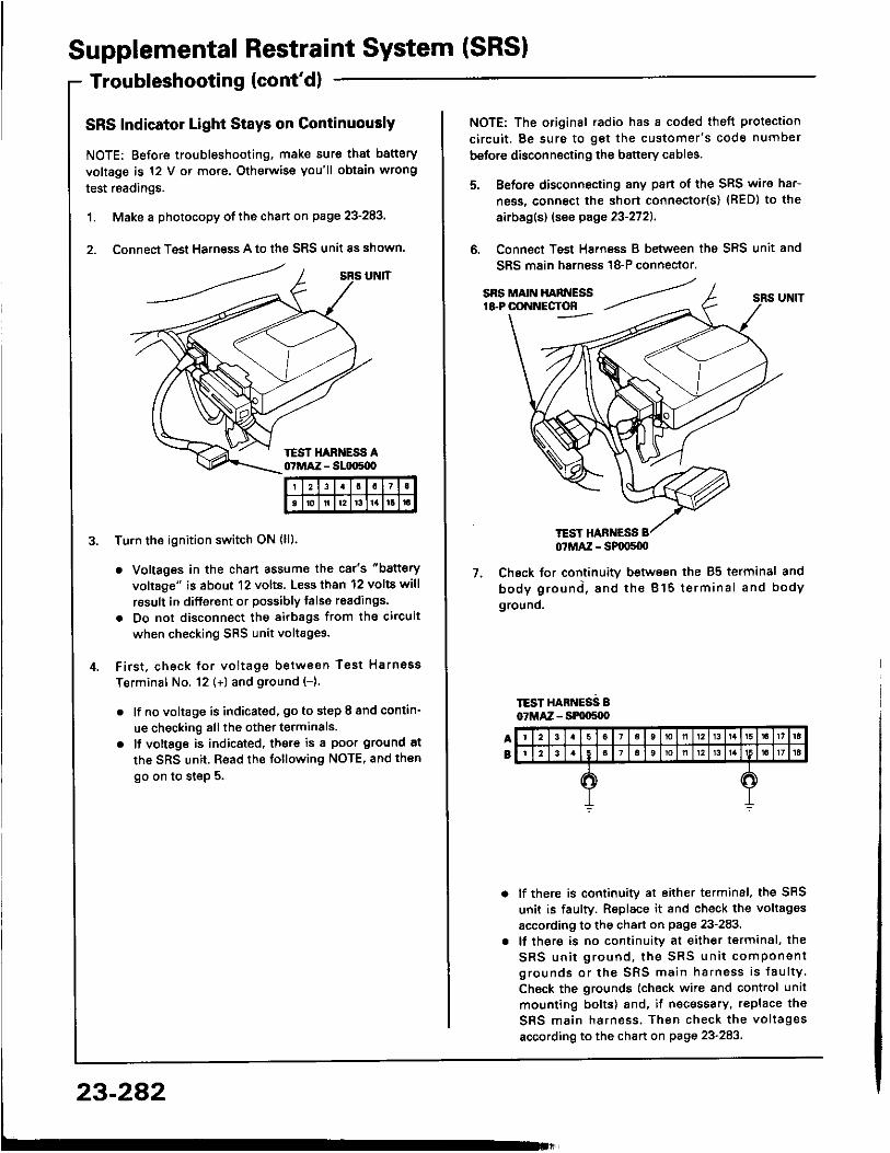
SRS Indicator Light Stays on ContinuouslyNOTE: Before troubleshooting, make sure that batteryvoltage is 12 V or mo.e. Otherwise you'l l obtain wrongtest readings.
1. Make a photocopy of the chart on page 23-283,
2. Connect Test Harness A to the SRS unit as shown.
Tu.n the ignition switch ON (l l l .
. Voltages in the chart assume the car's "batteryvoltage" is about 12 volts. Less than 12 volts wil lresult in different or possibly talse readings.
. Do not disconnect the airbags ftom the circuitwhen checking SRS unit voltages.
F i rs t , check fo r vo l tage be tween Tes t HarnossTerminal No. 12 (+) and ground (-).
. l f no voltage is indicated, go to step I and contin-ue checking all the other terminals.
o lf vottsge is indicated, there is a poor ground atthe SRS unit. Read the following NOTE, and thengo on to step 5.
I 2 1 I
to ll l2 t3 t l rt
23-282
TEST HANNESS
NOTE: The original .adio has a coded theft protectionc i rcu i t . Be sure to ge t the cus tomer 's code numberbefore disconnecting the battery cables.
Before disconnecting any pan of the SRS wire har-ness, connect the short connecto(s) {RED) to theairbag(s) (see page 23-2721.
Connect Test Harness B between the SRS unit andSRS main harn€ss 18-P connector.
7. Check for continuitv between the 85 terminal andb o d y g r o u n d , a n d t h e B l 5 t e r m i n a l a n d b o d yground.
TEST HARNESS B07MAZ - SPqrS{X)
lf there is continuity at either terminal, the SRSunit is faulty. Replace it and check the voltagesaccording to the chan on page 23-283.lf there is no continuity at either terminal, theS R S u n i t g r o u n d , t h e S R S u n i t c o m p o n e n tgrounds or the SRS main harness is fau l tyCheck the grounds (check wire and control unitmounting bolts) and, if necessary, replace th€SRS main harness . Then check the vo l tagesaccording to the chart on page 23-283
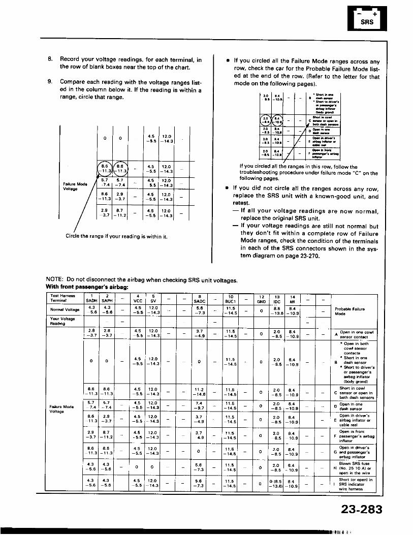
8. Record you. voltage readings. for each terminal, inthe row of blank boxes near the top of the chart.
Compare each reading with the voltage ranges l ist-ed in the column below it. l f ths reading is within arange, circle that range.
o o 4.5 1 2 , O1/4 .3
".)6r-at '9 \ r t .g
4.55.5
12.O- 14 .3
5. t 4 ,5 r 2 ,o- t 4 .34.6 2.9 rl.5
-5 .512.0
- 14.3
2 . 9 1 8 . 7 | l . . s l r 2 . o l3 . 7 l - r r . 2 l - | - 5 . 8 l - r a . 3 l -
Circle the range i f your reading is within i t .
NOTE: Do not disconnect the airbag when checking SRS unit voltages.Whh tront passongor's sirbag:
lf you circled all the Failure Mode ranges across anyrow. check the car for the Probable Failure Mode list-sd at the end of the row. (Refer to the letter for thatmode on the following pages),
I
/It you circl€d all the ranges in this row, tollow thetroubleshooting procedure under failure mode ,,C" on thefollowing pages.
lf you did not circle all the ranges across any row,replace the SRS unit with 8 known-good unit, andretest.- l f a l l your vo l tage read ings are now normal ,
replace the original SRS unit.- lf your voltage readings are sti l l not normal but
they don ' t f i t w i th in a comple te row o f Fa i lu reMode ranges, check the condition of the terminalsin esch of the SRS connectors shown in the svs-tom diagram on page 23-270,
1SAOH
2 5 aSADC
1 0aucl GNO
t 3tDc
4,35.4
4.3-5.6
4.5 12.0-14.3 t 1 , 5
- 1 4 . 5 o 1 3 . 64.4
- 10 .9
2 . 5-3.7
2_A 4.5 12.O- 1 r t .3
3.1-4,9
1 1 . 5- r 4 . 5 o 2.O
- 4 , 54.410.9
o o 4.5- 5 , 5
1 2 . 014_3 o 1 1 . 5
1 4 . 5 o 2.O4.5
8.4- 1 0 . 9
8 ,6l 1 _ 3
a_6- 1 1 . 3
4,55 . 5
1 2 . 0- 1 4 . 3
1 1 . 2- 1 4 . 6
1 1 . 5- 14 .5 o 2.O
4.54.41 0 . 9
5_7 4.5 12.0- 14.3 -9 .7
r 1 , 5- 1 4 , 5 o 2.O
4.58.4t o . 9
4 .6 2.9-3,7
4.5- 5 . 5
1 2 , O- 1 4 . 3
3,74.9
I 1 . 5l4_5 0 2.O
4.58.41 0 . 9
2 . 9 4.7- 1 1 . 2
4.5- 5 . 5
'12.o- 1 4 . 3 3.7
4.91 1 . 5
- 1 4 . 5 o 2.Oa_5
4.41 0 . 9
4 ,6l 1 _ 3
a_6- t 1 . 3
4.55 .5
1 2 . O- 1 4 . 3 o I t . 5
- r 4 . 5 o 2.O- 4 , 5
4 .41 0 . 9
4.3- 5 , 6
4.35.6 o o 1 1 . 5
- t l t .5 o 2.O- 4 . 5
4 .4- 1o .9
4.35,6
4_35.6
4.55 .5
12.Or4 .3 -7.3
1 1 . 5- 14 .5 o o 18.5- 13.6
4.41 0 . 9
23-283
Supplemental Restraint System (SRSITroubleshooting (cont'd)
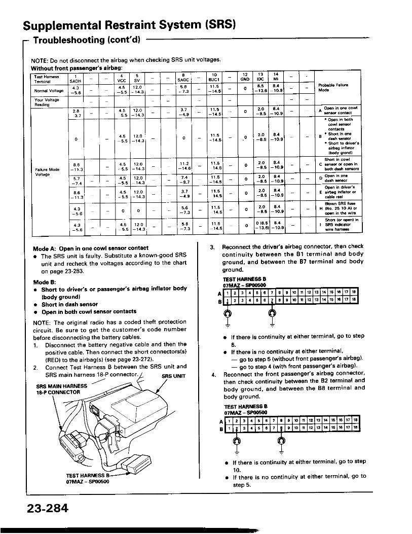
NOTE: Do not disconnect the airbag when checking SRS unit voltages.Without lront Passongor's sirbag:
Modo A: Open in one cowl sonsor conlactr The SRS unit is faultY. Substitute a known-good SRS
unit and recheck the voltages according to the charton page 23-283.
Mods B:. Short to driver's or Passonger's aitbag inflator body
(body groundl. Short in dash sonsor. Opsn in both cowl sgnsor contacts
NOTE: The original radio has a coded theft protectionc i rcu i t . Be sure to ge t the cus tomer 's code numberbefore disconnecting the battery cables.1. Disconnect the battery negative cable and then the
positive cable. Then connect the short connectots(s)(RED) to the airbag(s) (see page 23-272).
2. Connect Test Harness B between the SRS unit and
AB
SRS main harness 18-P connector. SRS UN]T'...
SRS MAIN HARNESS18.P CONNECTOR
3. Reconnect the driv€r's airbag connector, then checkcont inu i ty be tween the B1 te rmina l and bodyground, and b€twesn the 87 terminsl and bodygrounq,TEST HABT{ESS B
. lf there is continuity at either terminal, go to stepo.
. lf there is no continuity at sither terminal'- go to step 5 (without front passonge/s airbag)'- go to step il (with front passenger's airbag)'
Reconnect the front passonger's sirbag connector,then check continuity betwo€n ihs 82 t€rminal andbody ground, and between the 88 terminal andbody ground.
lf there is continuity at either terminal, go to step10.lf there is no continuity at either terminal, go tostep 5.
lSAOH vcc
5 8saoc
1 0BUCI
1 2Gto
1 3toc
t 4
4 , 35.6 5.5
12.O- 1 4 . 3
5 ,6-7 .3
1 1 . 5- 1 4 , 5 o a_5
- 1 3 . 68.:aro.9
2.43.7
4.55 .5
' t2.o1 4 . 3
3.74.9
1 1 , 5- 1 4 . 5 o 2.O
-8.58.4- r 0 .9
o 4.55,5
12.O- 1 4 . 3 o 1 1 . 5
- 1 4 , 5 o 2.O-8.5
8./a- r 0 . 9
4.6- 1 1 . 3 - 5 . 5
12.O- 1 4 . 3
1 1 . 2- 14 .6
1 1 . 514,5 o 2.O 8./t
- r 0 . 9
5 . 7 4.5 t2.o1 4 , 3 -9.7
t t . 5- 14_5 o -8.5
8.1-10 .9
4 .61 1 . 3
4.5- 5 . 5
12.0- 14.3
3.7-4.9
1 t . 514.5 o 2.O
-8.5a.a-r0.9
4.3 o o 5,6-7 .3
1 1 . 514,5 o 2,O 8.it, r 0 .9 H ll{o. 26 lo Al o.
4.3- 5 . 6
4.5-5 .5
12.O- 1 4 . 3 -7.3
t 1 . 5- 14-5 o o ta,5
- 13.0tE,4
-10.9
23-284

Check continuity between body ground and eachterminal of both dssh sensors.
TEST HARNESS Bo?MAZ - SFmSd)
. lf there iscontinuity at anyof theterminals, go tostep 12.
. lf thsre is no continuity at any terminal, go tosteo 13.
Disconnect the cable reel 6-p connector from theSRS main harn€ss, then connect Test Harness Conly to the cable reel side of the 6-p connector.
CABLE NEEL &P CONNECTOR
7. Check continuity between the No. 4 terminal andbody ground, and between the No. 5 terminal andbody ground.
TEST HABI{ESS C07LAiZ - SLIO:loo
lf there is continuity at either terminal, go to step8.
lf there is no continuity at either terminal, theSRS main harness is faulty. Replace it and re_chsck the vo l tages accord ing to the char t onpage 23-283.
(cont'd)
23-285
Supplemental Restraint System (SRS)Troubleshooting {cont'd}
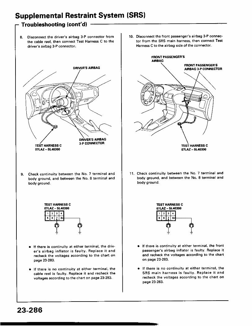
8. Disconnect the drive/s airbag 3-P connector tromthe cable reel, then connect Test Harness C to thedriver's airbag 3-P connector.
Check continuitv between the No. 7 terminal andbody ground, and between the No. 8 terminal andbody ground.
lJ there is continuity at either terminal, the driv-e r ' s a i rbag in f la to r i s fau l ty . Rep lace i t andrecheck the voltages according to the chart onpage z3- z6J.
lf there is no continuity at either terminal, thecable reel is faulty. Replace it and recheck thevoltages according to the chart on page 23-283.
DRIVER'S AIRBAG
23-286
10. Disconnect the front passenger's airbag 3-P connec-tor from the SRS main harness, then connect TestHarness C to the airbag side of the connector.
FRONT PASSENGER'SANBAG
Check continuitv between the No. 7 terminal andbody ground, and between the No. 8 te.minal andbody ground.
lf there is continuitv at either terminal, the Jrontpassenger's airbag inflator is faulty. Replace itand recheck the voltages according to the charton page 23-283.
lf there is no continuitv at either terminal, theSRS main harness is fau l ty . Rep lace i t andrecheck the voltages according to the chart onpage 23-283.
1 1 .
o7LAiZ - Slao:tq,
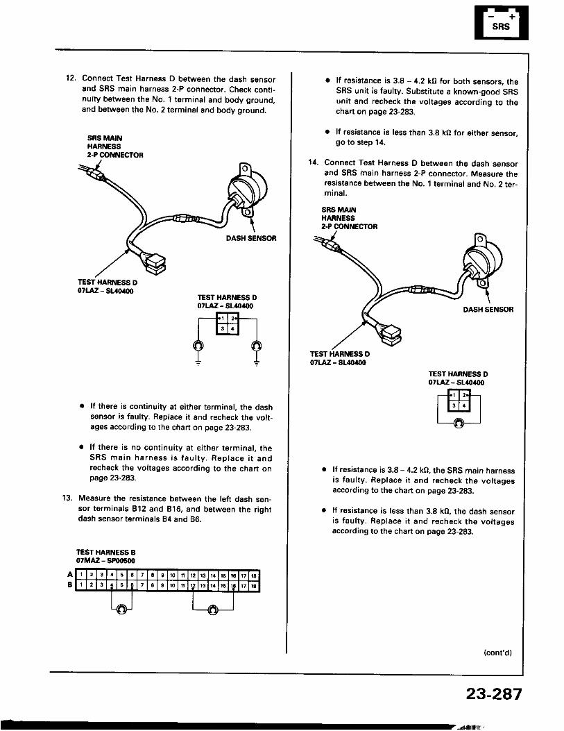
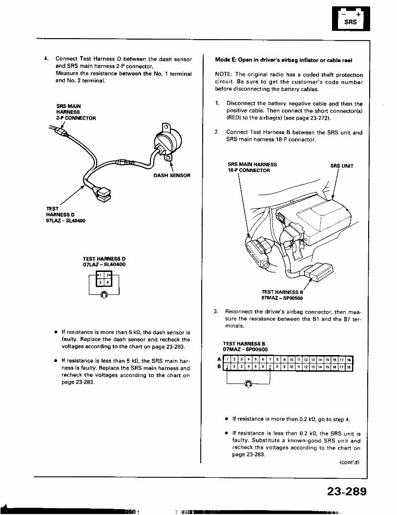
12. Connect Test Harness D between the dash sensorand SRS main harness 2-P connector. Check conti-nuity between the No. 1 terminsl and body ground,8nd between the No.2 terminal and body ground,
sRs MA[{HARNESS2-P OOTTNECTOR
TEST HARNESS Do?LAiZ - SL()a(xt
. lf there is continuity at either terminal, the dashsensor is faulty. Replace it and recheck the volt-ages according to the chan on page 23-293.
. lf there is no continuity at either terminal, theSRS main harness is fau l ty . Rep lace i t andrecheck the voltages according to the chart onpage 23-283.
Measure the resistance between the l6ft dash sen-sor terminals B'12 and Bl6, and between the rightdash sensor terminals B4 and 86.
IEST HARNESS B07MAZ - SPqt500
TEST HARNESS DotlA:z - sl(,(x)
rffi-l? ?
t'l
o lt rssistance is 3.8 - 4.2 kO for both sensors. theSRS unit is faulty. Substitute a known-good SRSunit €nd recheck the voltages according to th€chart on page 23-283.
o lf resistancs is l6ss thsn 3.8 kO for either sensor.go to step 14.
1il. Connect Test Harness D between the dash sensorand SRS inain harness 2-P connector. Measure theresastance between the No. 1 terminal and No. 2 ter-mina l .
SRS MAINHARNESS2.P CONNECTOR
TEST HAR ESS D07LAZ - SL.{)a(xl
TEST XARNESS DotlA:z - sl4|)4tx)
lf resistance is 3.8 - 4.2 kO, the SRS main harnessis faulty. Replace it and recheck the voltagesaccording to the chan on pag€ 23-283.
lf resistance is less than 3.8 kO, the dash sensoris faulty. Replace it and recheck the vottagesaccording to the chart on psge 23-283.
(cont'd)
23-287
Supplemental Restraint System (SRS)Troubleshooting (cont'd)
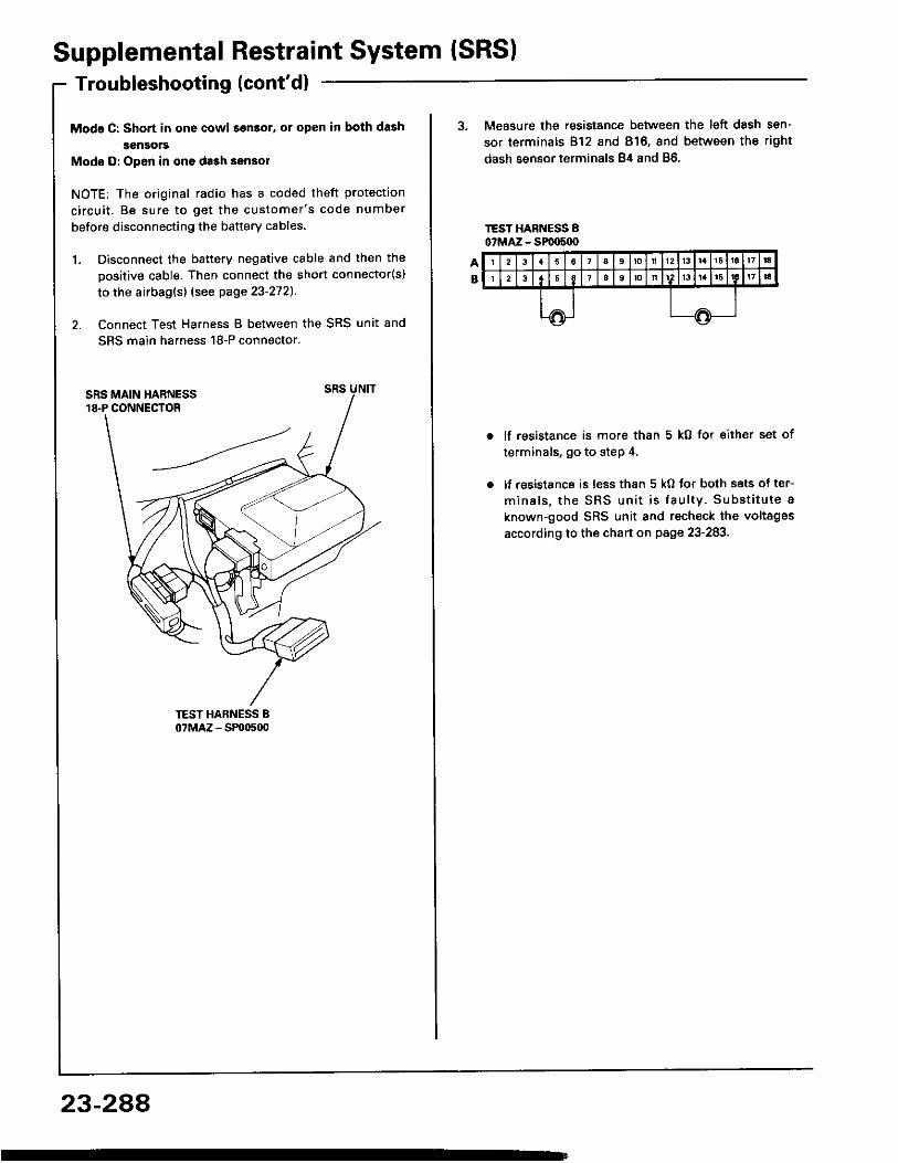
Modg C: Shon in one cowl son3ol, or open in both dashsensors
Mode D: Open in ono da3h sensol
NOTE: The original radio has a coded theft protectionc i rcu i t . Be sure to ge t the cus tomer 's code numberbefore disconnecting the battery cables
1. Disconnect the battery negative cable and then thepositive cable. Then connect the short connector(s)to the airbag(s) (see page 23'2721.
2. Connect Test Harness B between the SRS unit andSRS main harness 18-P connector.
23-2AA
3. Measure the resistance between the left dash sen-sor terminals 812 and 816, and between the rightdash sensor terminals 84 and 86.
lf resistance is more than 5 kO for eiiher set ofterminals, go to step 4.
lf resistance is less than 5 kO tor both sets of ter-mina ls , the SRS un i t i s fau l ty . Subs t i tu te aknown-good SRS unit and recheck the voltagesaccording to the chart on page 23-283.
4. Connect T6st Harness D between the dash sensorand SRS main harness 2-P connector.Measure the resistance between the No. 1 terminaland No. 2 terminal.
SBS MAINHARNESS2-P COI{NECTOR
TESTHARNESS DorlA:a - sl{tarx)
TEST HARI{ESS DOTLAZ - sl/to4{lo
lf resistance is more than 5 kO, the dash sensor isfaulty. Replace the dash sensor and recheck thevoltages according to the chart on page 23-283.
lf resistance is less than 5 kO, the SRS main har-ness is faulty. Replace rhe SRS main harness andrecheck the voltages according to the chart onpage 23-283.
Mode E: Op€n in driver's airbag inflator or cable reel
NOTE: The original radio has a coded theft protectionc i rcu i t . Be sure to ge t the cus tomer 's code numberbefore disconnecting the baftery cables.
Disconnect the battery negative cable and then thepositive cable. Then connect the short connector(s)(RED)to the airbag(s) (see page 23-272).
Connect Test Harness I between the SRS unit andSRS main harness l8-P connector.
sRs uNtt
Reconnect the driver 's airbag connector, then mea-sure the resistance between the 81 and the 87 ter,mr na l s .
TEST HARNESS Bo?MAZ - SP00500
lf resistance is more than 0.2 kO, go to step 4.
lf resistance is less than 0.2 kO, the SRS unit isfau l ty . Subs t i tu te a known-good SRS un i r andrecheck the voltages according to the chan onpage 23-283.
(cont'd)
23-289; r.il M
1 .
2 .
Supplemental Restraint System (SRS)Troubleshooting {cont'd}
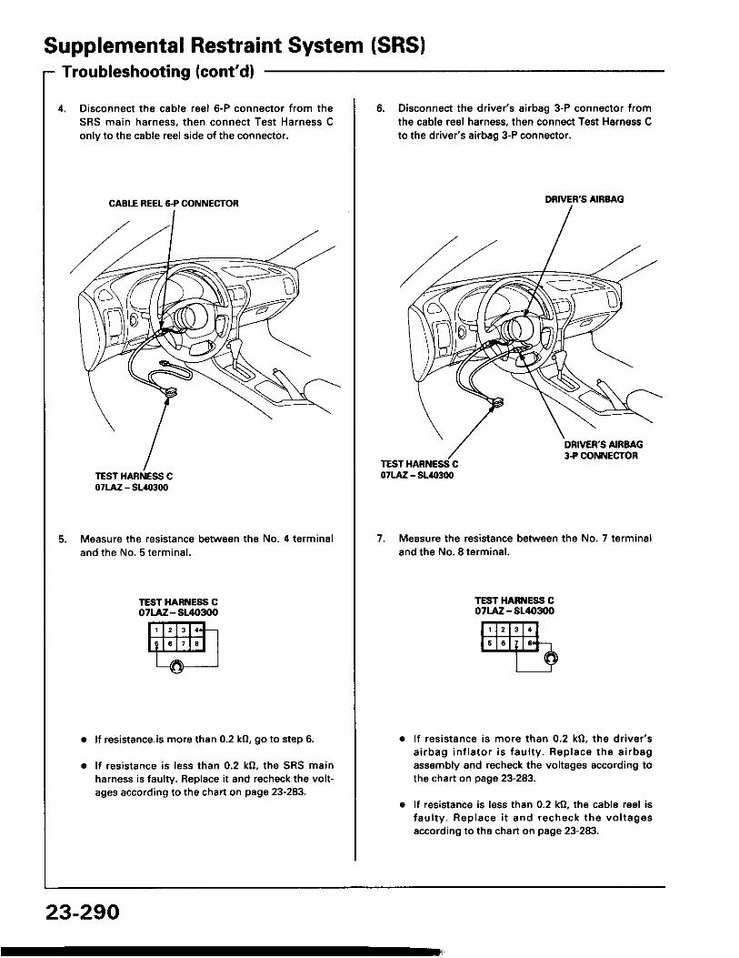
4, Disconnect the cable reel 6-P connector from theSRS main harness, then connect Test Harness Conlv to the cable reel side ot the connector.
CAB1I REEL &P CONNECTOB
TEST HARNESS C07LAZ - SLIO300
Measure the resistance between the No. 4 terminaland the No, 5 terminal.
TEST HARI{ESS COTLAiZ - Sl/t{r3q)
lf resistance.is more than 0.2 ko, go to step 6.
It resistance is less than 0.2 k0, the SRS mainharness is faulry. Replace it and recheck the volt-ages according to the chart on page 23-283.
23-290
6. Disconnect the driver's airbag 3-P connsctor fromthe cabls reol harness, then connoct Test Harn6ss Cto the driver's airbag 3-P conn6ctor.
DRIVER'S AIRBAG
7. Measure the resistance between the No. 7 terminsland the No. 8 terminal.
TEST HARI{ESS COTLAZ - AL/|{,3OO
lf resistance is more than 0.2 kO, ths drivsr'sa i rbag in f la to r i s fau l ty . Rep lace the a i rbsgass€mbly and recheck the voltages according tothe chart on page 23-283,
lf resistance is less than 0.2 kO. the cable reel isfau l ty . Rep lace i t and recheck the vo l tag€saccording to the chart on page 23-283.
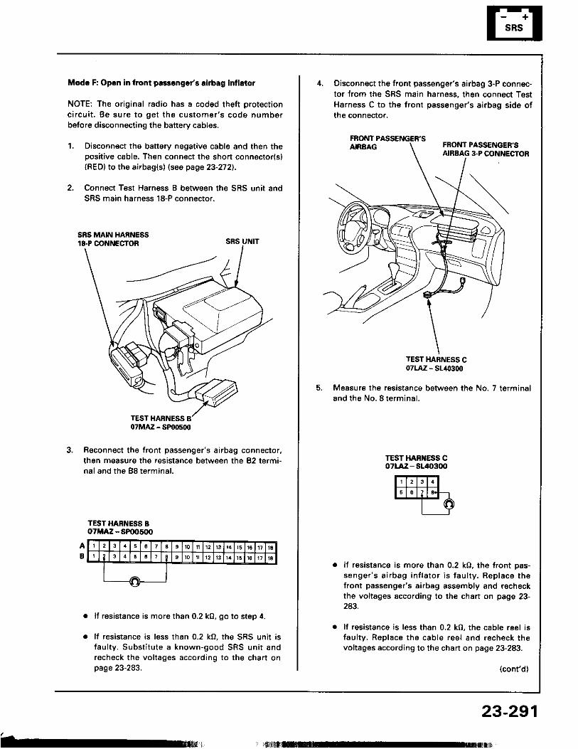
Modc F: Opon in tront pa3s6ngs/s rirbag inflstor
NOTE: The original radio has a coded theft protectionc i rcu i t . Be sure to ge t the cus tomer 's code numberbefore disconnecting the battery cables.
1, Disconnect the battery negative cable and then thepositive cable. Then connect the short connoctor{sl{RED} to the airbag(s) (see page 23-272).
2. Connect Test Harness B between the SRS unit andSRS main harness 18-P connector.
SRS UNIT
Reconnect the front passenger's airbag connector,then measure the resistance between the 82 termi-nal and the B8 terminal.
TEST HARNESS BoTMAZ - SP005(x)
lf resistance is more than 0.2 k0, go to step 4.
lf resistance is less than 0.2 kO, the SRS unit isfaulty. Substitute a known-good SRS unit andrecheck the voltages according to the chart onpage 23-283.
b
07MAZ - SP|D500
Disconnect the front passenger's airbag 3-P connec-tor from the SRS main harness, then connect TestHarness C to the front passenger's airbag sids ofthe connector,
FAONT
TEST HARNESS C07LA,Z - SL/O300
Measure the resistance between the No. 7 terminaland the No. 8 te rmina l .
TEST HAB ESS C071-Aiz - sll|{,300
lf resistance is more than 0.2 kO, the front pas-senger 's a i rbag in f la to r i s fau l ty . Rep lace thefront passenger's airbag assembly and r€checkthe voltages according to the chart on page 23-243.
lf resistance is less than 0.2 kO, the cable reel isfaultv. Replace the cable reel and r€check thevoltages according to the chart on page 23-283.
(cont'd)
23-291
Supplemental Restraint System (SRSITroubleshooting {cont'dl
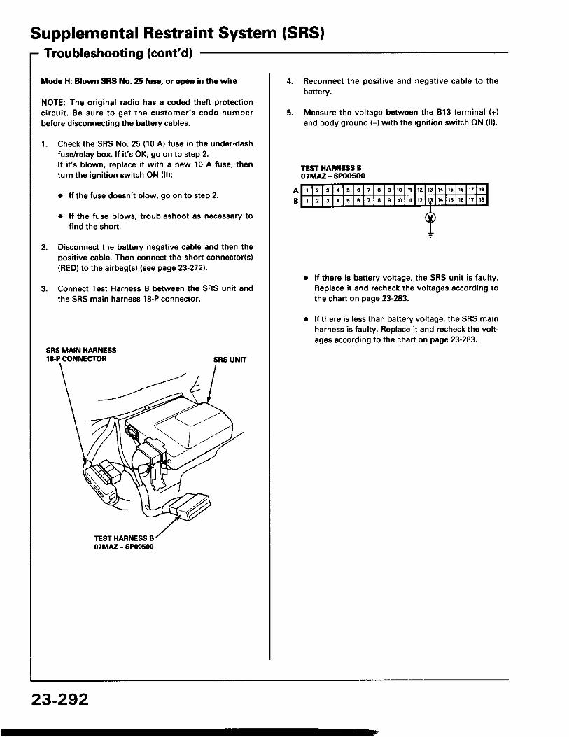
Modc H: Blown SRS No. 25 fur., ol opcn in the wire
NOTE: The original radio has a coded theft protectioncircuit. Be sure to get the customer's code numberbetore disconnecting the battery cables.
1. Ch€ck the SRS No. 25 (10 A) fuse in the under-dashfuse/relay box. lf it's OK, go on to step 2.lf it's blown, replace it with a now 10 A fuse, thenturn the ignition switch ON (l l):
. lf the fuse doesn't blow, 90 on to step 2.
. lf the fuse blows. troublsshoot as necessary tofind th6 short.
2. Disconnect the battery negative cable and then thepositive cable. Then connect the short connector(sl(RED) to the airbag(s) (see page 23-272).
3. Conn€ct Teat Harnsss B between the SRS unit andthe SRS main harness 18-P connector.
SRS UNIT
23-292
2 3 a 7 a 10 n l3 1 6 1a 17 ra2 6 1 6 1o ll 12 16 1a 17 |a
Reconnect th6 positiv€ 8nd negative cable to thebattery.
Measure ths voltage between the 813 terminal (+)and body ground {-)with the ignition switch ON (l l).
TEST HAN ESS BoTMA:Z - SPOOs{X'
lf there is battery voltage, the SRS unit is faulty.Replace it and rscheck the voltages according tothe chan on page 23-283.
lf there is lsss than b8ttery voltage, the SRS mainharness is faulty. Replace it and recheck the volt-ag6s according to the chart on page 23-283.
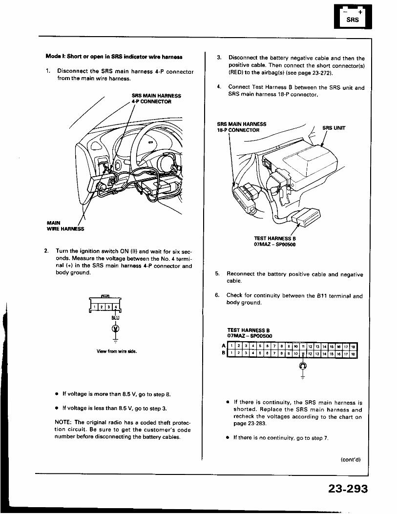
Modc l: Short 01 opcn in SRS indicrtor whc hrrnaas
1. Disconnect tho SRS main harness 4-p connectorfrom the main wirs harn6ss.
WIRE HABNESS
2. Turn the ignition switch ON (l l) 8nd wait for six sec-onds. Measu.s the voltage between ths No. il termi-nal (+) in the SFS main harness 4-P connector andbody ground,
. lf voltage is more thsn 8.5 V, go to step 8.
. It voltage is less than 8.5 V, go to step 3.
NOTE: The original radio has a coded theft protec-tion circuit. Be sure to get the customer's codenumber before disconnecting the banery cables.
*-F4BLU
d.L
Vrow llom wi|! rftro.
Disconnect the battery negative cable and then thepositive cable. Then connect the sho.t connector(s)(REDlto the airbag(s) (see page 23-272).
Connect Test Harness B between the SRS unit andSRS main harness 18-P connector.
5. Reconnect the battery positive cable and negativecaote.
6, Check for continuity between the 811 terminalbody ground.
lf there is continuity, the SRS main harness isshor ted . Rep lace the SBS main narness anorecheck the voltages according to the chart onpage 23-283.
lf there is no continuity, go to step 7.
(cont'dl
23-293
SupplementalTroubleshooting(cont'dl
RestraintSystem (SRSI
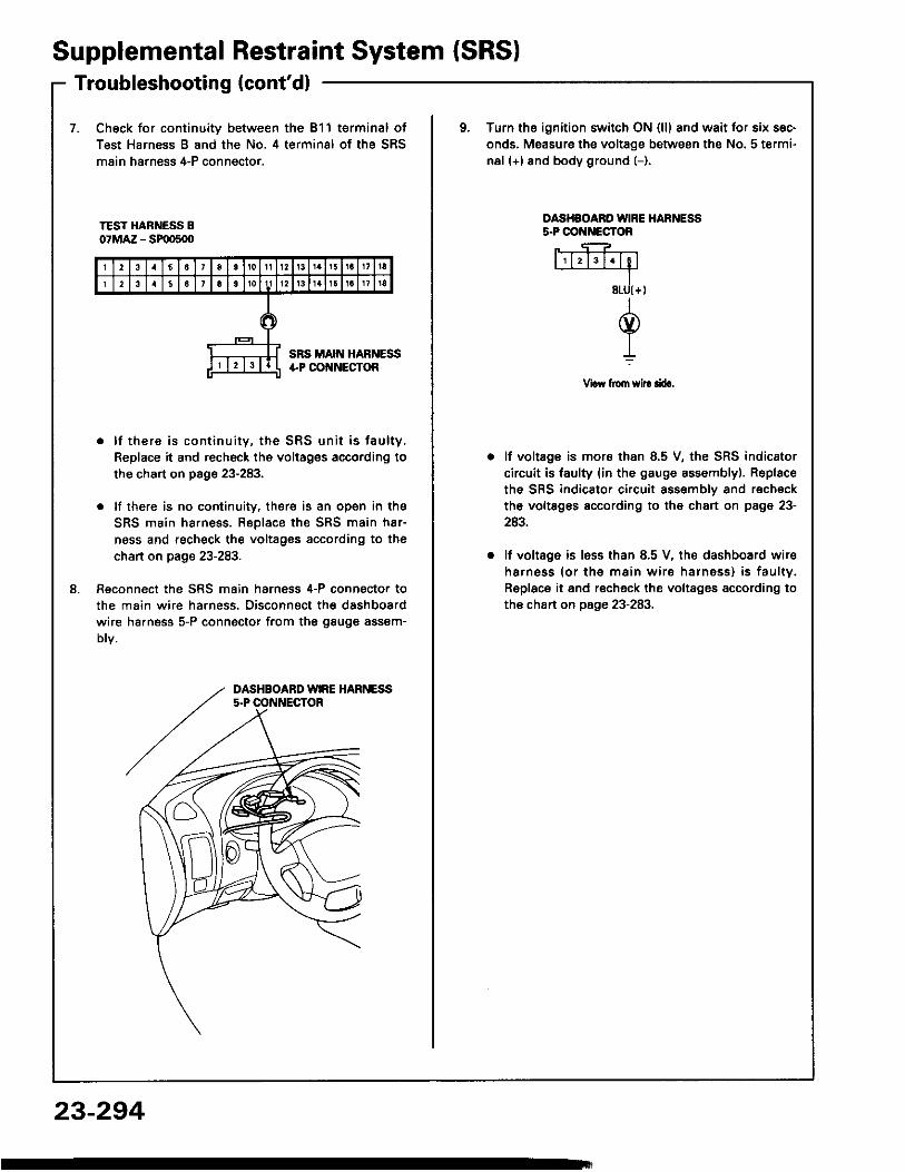
7. Check for continuity between the 811 terminal ofTest Harness B and the No. 4 terminal of the SRSmain harness 4-P conngctor,
o Turn ths ignition switch ON {l l} and wait for six sec-onds. Measure the voltage between the No. 5 termi-nal (+) and body ground (-).
TEST HARNESS B07MAZ - SF|D500
OASHSOARO IVIRE HARNESSs.PCO ECTOR
Vraw from sil! rira,
8 .
. l f there is con t inu i ty , the SRS un i t i s fau l ty ,Replace it and recheck the voltages according tothe chart on page 23-283.
. lf there is no cootinuity. there is an open in theSRS main harness. Replace the SRS main h8r-ness and recheck the voltages according to thechart on page 23-283.
Reconnect the SRS main harness 4-P connecto. tothe main wire ha.ness. Disconnect the dashboardwire ha.ness 5-P connector from the gauge assem-Dtv.
lf voltage is mora than 8.5 V, the SRS indicatorcircuit is faulty (in the gauge assemblyl. Replacethe SRS indicator circuit assembly and recheckthe voltsges according to the chart on page 23-243.
lf voltage is less than 8.5 V, the dashboard wireharness (o r th€ ma in w i re harness) i s fau l ty .Replace it and recheck the voltages according tothe chart on page 23-283.
DASHBOARD WIRE HARNESS5.P OONNECTOR
23-294
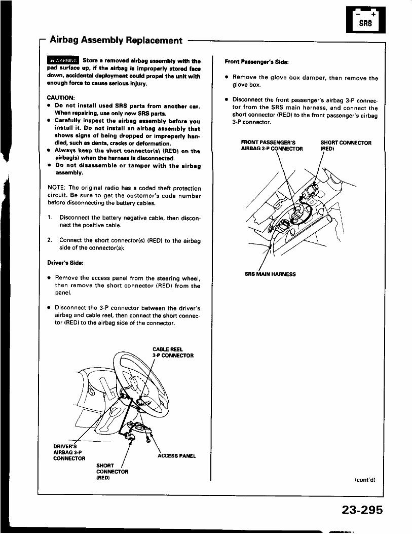
Airbag Assembly Replacement
@E storc a r.movcd lirb.g rslombty with thcp.d surfaco up, if tho lirbrg is improparly 3iorad frcadown, accidontal d.ploymert could plopcl tha unit withcnough torcr lo causc lariour iniury.
CAUTION:. Do not inst.l l urld SRS plrts trom lnothar c!1,
Whon lepairing, uss only now SRS prrt!.o Carefully inlpcct thc airblg rlrcmbly bltorc you
install i t. Do not inst.l l an airbag !$.mbly thrt3how! sign3 of bcing droppcd or improparly hrn-dlod, such as dont!. crack3 or dstormation.
. Alwry! koop ths rhort connactor(3l (REDI on thaairbrg{s} whon tho hsrnca3 i! dirconnastld.
. Do not diras3ombl! or tamp€l with tha l irbrga$ombly.
NOTE: The original radio has a coded th6ft protectionc i rcu i t . Be sure to ge t the cus tomer 's code numberbefore disconnecting the battery cables.
1. Oisconnect the battery nogative cabl6, then discon-nect the positive cable.
2. Connect the short connecto(s) (R€D) to the aifbagside of the connector(s);
Drivo/s Sido:
a Remove the access panel from the steering whesl,then ramove the short connector (REDI from th6paner.
. Disconnect the 3-P connector betwesn the driv6r'sairbag and cable reel, then connect th6 short connec-tor {RED} to the airbag side of the connector.
Fror{ P$!.ngar/3 Sida:
. Remove th6 glove box damper, then remove theglove box.
. Disconnoct the front psssenger's airbag 3-p connec-to r f rom the SRS main harness , and connect theshort connoctor (RED) to the front passenger,s airbag3-P connector.
FROIVTPASS€NGEF'S SHOBTOONNECTORAIRBAG 3.P CONNECTOR (REDI
(cont'd)
23-295,ry!$,
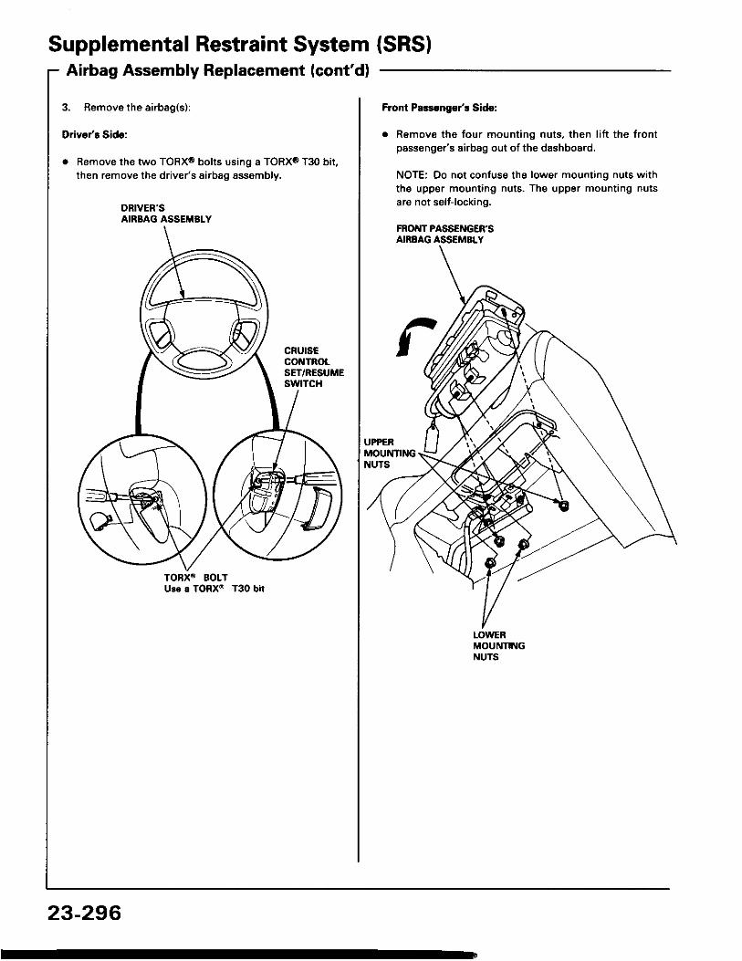
Supplemental Restraint System (SRSIAirbag Assembly Replacement (cont'd)
3. Remove the airbag(s):
Driver's Side:
. Remove the two TORXo bolts using a TORX0 T30 bit,then remove the driver's airbag assembly.
DRIVER'SAIRBAG ASSEMBLY
23-296
Front Palsugor'r Sidc:
. Remove the four mounting nuts, then lift the frontpassenger's airbag out of the dashboard.
NOTE: Oo not confuse the lower mounting nuts withthe upper mounting nuts. The upper mounting nutsare not selt-locking.
FRONT PASSENGER'SAIBBAG ASSEMBLY
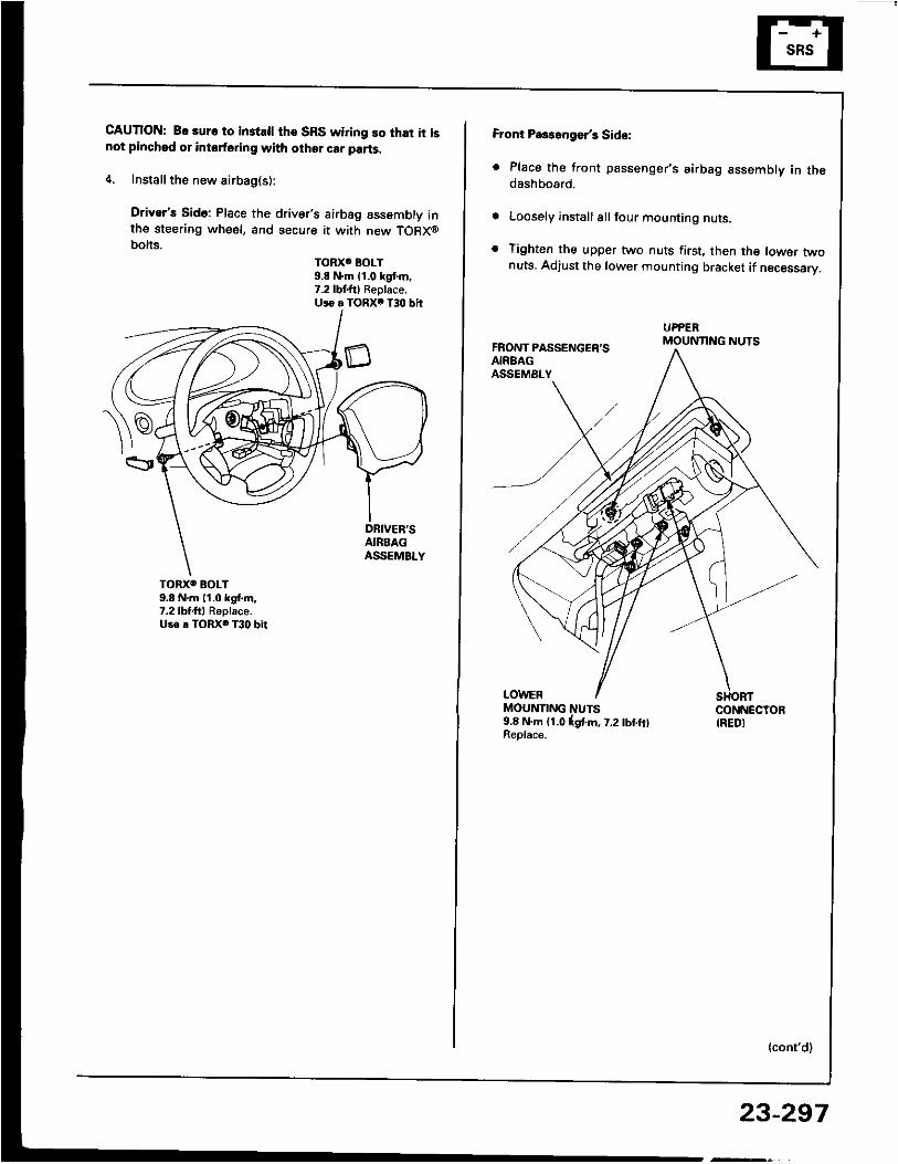
CAUTION: Bo 3uro to in3tsll tho SRS wiring so that it isnot pinchod or intoforing with other car parts.
4. Install the new airbag(s):
Driver's Sido: Place the driver's airbag assembly inthe steering wheel, and secure it with new TORX@bolts.
TORXC BOLT9.8 N'm 11.0 kgt m.7.2lbf.ftl Replace.Uio a TORXO T30 bit
TORXO BOLI9,8 N'm l'1.0 kgf.m,7.2lbtf t l Replaco.Us. . TORX6 T30 bit
Front Pa$aogsr's Sid€:
. Place the front passenger's airbag assembly in thedashboard.
Loosely install all four mounting nuts.
Tighten the upper two nuts first, then the lowsr twonuts. Adjust the lower mounting bracket if necessarV.
FRONT PASSENGER'SAIRBAGASSEMALY
UPPERMOUNTING NUTS
LOWERMOUNTING NUTS9.8 N.m (1.0lgtm, t .2lbtf t lReolace.
CONNECTORIREDI
{cont'd)
23-297
Supplemental Restraint System (SRSIAirbag Assembly Replacement (cont'd)
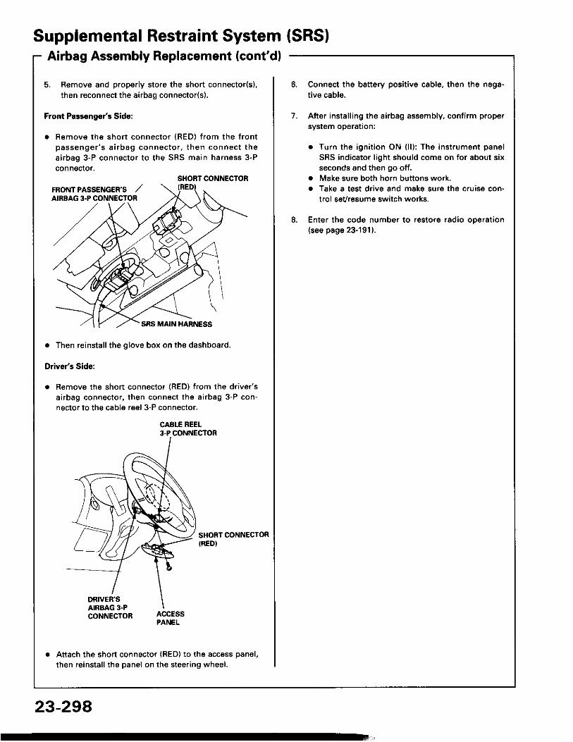
5. Remove and properly store the short connector(s),then reconnect the airbag connector(s).
Front Pass€ng€r's Side:
. Remove the short connector (RED) from the frontpassenger 's a i rbag connector , then connect theairbag 3-P connector to the SRS main harness 3-Pconnector.
. Then reinstall the glove box on the dashboard,
Driver's Side:
Remove the short connector (RED) from the driver'sairbag connector, then connect the airbag 3-P con-nector to the cable reel 3-P connector.
CABI-E REEL3-P CONNECTOR
SHORT CONNECTORIRED)
DRIVER'SAIRBAG 3.PCONNECTOR
Attach the short connector (RED) to the access panel,then reinstall the panel on the steering wheel.
SHORT CONNECTORFRONT PASSENGER'S ,,'AIRBAG 3.P CONNECTOR
Connect the battery positive cable, then the nega-tive cable.
After install ing the airbag assembly, confirm propersystem operataon:
. Turn the ignition ON (l l): The instrument panelSRS indicator l ight should come on for about sixseconds and then go off.
. Make sure both horn buttons work.a Take a test drive and make sure the cruise con-
trol sevresum€ switch works.
Enter the code number to restore radio oDeration(see page 23-191).
7 .
8 .
23-294
Airbag Assembly Disposal
Before scrapping any airbag(s) (including one in a wholecar to be scrappedl, the airbag must be deployed. t{ thecar is still within the warranty period, before you deplovthe ai.bag, the Acura District Service Manager must giveapproval and/or special instructions. Onlv after the air-ba9 has been deployed (as the result of vehicle coll ision,for example),it can be scrapped.lf the airbag(s) appear(s) intact (not deptoyed, treat it{them) with extreme caution.Follow this Drocedure:
Doploying the Airbag(sl: In-car
NOTE: l f an SRS car i s to be en t i re ly sc rapped. i t sairbag(s) should be deployed while sti l l in the car. Thea i rbag(s ) shou ld no t be cons idered as sa lvageab lepan(sl and should never be installed in another car.
@ conf i rm tha t osch a i rbsg assembly i ss6cursly mounted; oihorwis6. s€voro parsonal iniurycould result from doployment.
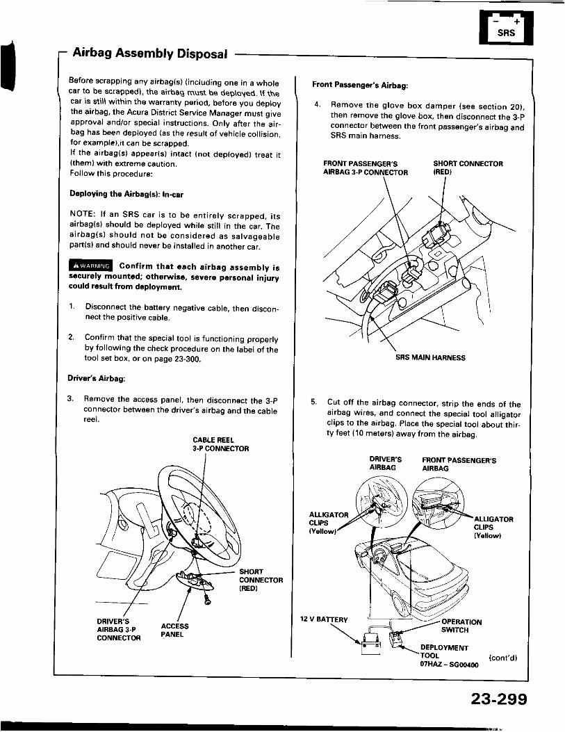
1. Disconnect the banery negative cable. then discon_nect the Dositive cable.
2. Confirm that the special tool is functioning properlyby following the check procedure on the label of thetool set box, or on page 23-300,
Driver's Airbag:
3. Remove the access panel, then disconnect the 3_pconnecto. between the driver's airbag and the cablereel.
CABLE REEL3.P CONNECTOR
Front Passonger's Airbag:
4 . Remove the g love box damper (see sec t ion 2O) .then remove the glove box. then disconnect the 3-pconnector botween the front passenger,s airbag andSRS main harness.
FRONT PASSENGER'S SHORT CONNECTORAIRBAG3.PCONNECTOR IRED}
Cut off the airbag connector, strip the ends of theairbag wires, and connect the special tool all igatorclips to the sirbag. Place the special tool about thir_ty feet (10 meters) away from the airbag.
DRIVER'S FRONTPASSENGER'SAIRBAG AIRBAG
12 V BATTERV
ALLIGATORCLIPSlY.llowl
OPERATIONswrTcH
DEPLOYMENTTOOI (cont,dl07HAZ - SG00400
23-299
SRS MAIN I{ARNESS
Supplemental Restraint System (SRSIAirbag Assembly Disposal (cont'd)
Connect a l2 volt batterv to the tool:
. l f the green l igh t on the too l comes on , th€a i rbag ign i te r c i rcu i t i s d€fec t i ve and cannotd e p l o y t h e a i r b a g . G o t o D s m a g€d A i r b a gSpecial Procedure.
. lf the red l ight on the tool comes on, the airbag isready to be deployed.
Push the too l ' s dep loyment sw i tch . Th6 s i rbagshould deploy (deployment is both highly audibleand visibls - a loud noise and raDid inflation of thebag, followed by slow deflationl.
. l f audible/visible deploym€nt happsns and thegreen light on the tool comes on, continus withthis Drocedure.
. lf the airbag doesn't deploy, yet the green lightcomes ON, i t s ign i te r i s do fec t iv€. Go toDamaged Airbag Special Procedure.
@ During deploym€nt, the airbsg assom-bly can become hot enough to burn you. Wait thirtyminu tes a f te r dep loyment be foro touch ing theassemblv.
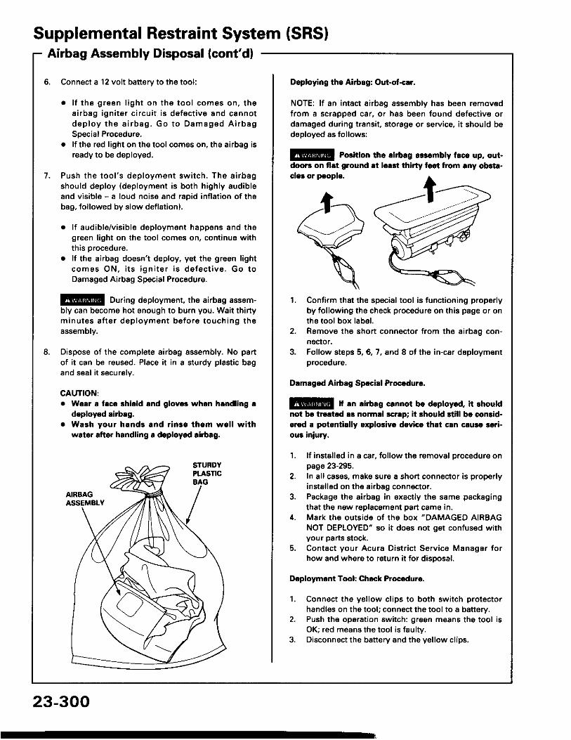
Dispose of the complete airbag sssembly. No panof it can be reused. Place it in I sturdy plastic bagand seal it securelv.
CAUTION:Woar a taco shiold lnd glov.s whon hlndling !doploy.d airbag.Waeh your hands and rin3a tham wall withwslor aftor handling r deploycd !irb!g.
23-300
Doploying the Airbag: Out-ot{!r.
NOTE: lf an intsct airbag assembly has been removedfrom a scrapped car, or has been found dofective ordamagsd during transit, storage or service, it should bsdsployed as follows:
@ Porition th6 lirbrg rr:.mbly t.ce up, out-doo6 on flat ground !t lorrt thirty foot from rny ob3t..clar or pcoplo.
1. Confirm that the special tool is functioning properlyby following the check procedure on this page or onthe tool box label.
2. Remove the short connector from the airbag con-nector.
3. Folfow steps 5,6,7, and 8 of the in-car deploymentorocequre.
Dlmlged Airbsg Sp.ci8l Procoduro.
E!@ f rn lirbag crnnot be deploy.d, it rhouldnot br trcltcd !s normll scrrp; ii 3hould still bc comid-ercd a potantillly oxplolivr dcvicc thli cln c!u3a 3ari-ou3 iniury.
1. lf instslled in a car, follow the removal procedure onpage 23-295.
2. In all cases, make sure a short connector is properlyinstalled on the airbag conn€ctor.
3. Package the airbag in sxacily the same packagingthat the now replacement part cama in.
i[. Mark the outside 0f the box "DAMAGED AIRBAGNOT OEPLOYED" so it does not get confused withyour parts stock.
5. Contact your Acura District Service Manager forhow and where to return it for disoosal.
Dcploymont Tool: Chcck Procedure.
1. Connect the yellow clips to both switch protectorhandles on the tool; connect the tool to a battery.
2. Push th€ operation switch: green means the tool isOK; red means the tool is faulty.
3. Disconnect the battery and the yellow clips.
Cable Reel Replacement
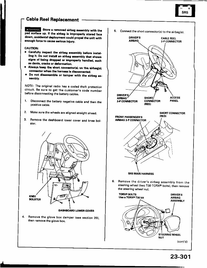
!!@ store r rcmov.d rirbrg rsldnbty with thrprd ruf.cc up. It th. .irb.g i3 impropcrly 3to.rd f.ccdown, sccid.ntd d.ploym.rf could propcl th. unit withrnough torca to caure a.?iour iniury.
GAUTION:o Clrdully in3pcct thc airbrg r$.mbly brtorc instll_
ling it. Do not inttrll !n lirb.g |3..mbly ihst fiow3rignr of bring droppcd or improp.rly handled. ruch.3 dant!, crrck3 or dafo?mation.
. Atw!$ krro th. tkroR connctot(3l on ths rtbrg\t\connactor whan tha h|rn!|a l! dbconncstad,
. Do lo-t dis.tlambla or tampar with thc ai.brg !r-t.mbly.
NOTE: The original radio has a codod theft Drotoctionc i rcu i t . Bs sure to ge t the cus tomer ,s code numberbsfore disconnecting th6 battery cables.
l. Disconnect th6 banory negstive cable and thsn thepositive cable.
2. Make sure the whe€ls are aligned straight ahoad.
3. Removo th€ dashbosrd lowsr covsr and kne6 bol_$er.
DASHBOANO LOWER OOVER
Removs tho glove box damper (s6e s€ction 2O),then remove the glove box,
-
23-301
IRED}
5. Connect the sho.t connector(s) to the airbag(s).
DRIVER'SAIRBAG
Remove the dr iver ' s a i rbag assembly f rom thesteerang wheel (two T30 TORXO bolts), then removethe steering wheet nut.TOR)(' BOLTSU.. . TORX. T30 bh
DRIVER'SAIRBAGASSEMBLY
(cont'd)
SRS MAIN HARNESS
Supplemental Restraint System (SRSIGable Reel Replacement (cont'd)
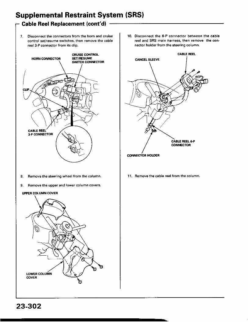
Disconnect the connectors from the horn and cruisecontrol sevresume switches, then remove the cablereel 3-P connector from its cliD.
8. Remove the steering wheel from the column.
9. Remove the upper and lower column covers.
UPPER COLUMN COVER
23-302
10. Disconnect the 6-P connector between the cablereel and SRS main harness, then remove the con-nector holder from the steering column.
'l l . Remove the cable reel from the column,
CABIT BEEL
CONNECTOF HOI-DER
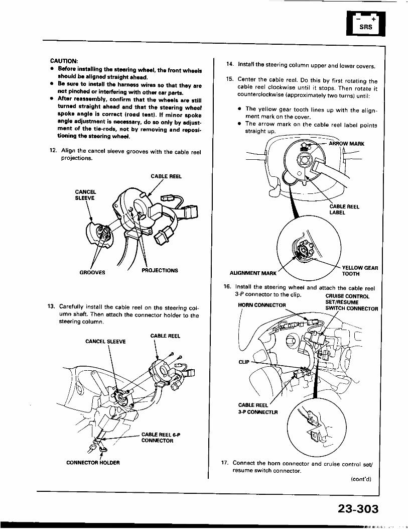
GAUTION:o Eatora instdling tho steoring whosl, lha front whaels
lhould bo alignod straight !ho!d.. Bc auro to imtalt tho hrrnass wiros so that th6y !16
not pinchod or intsrt6ring with othor crr parts.. Aftor rsassambly. conlirm that tho whods lre 3till
turnad straight ahead and lh.t the steering wheolrpoko angle is corrsct {rosd tesi}. lf mino. spok€angl6 adiustmont is necols!ry, do 30 only by ldiust_mgnt ol tho tio-rod9. not by removing and rgposi-tioning tho rteering whoel.
12. Align th€ cancel sleeve grooves with the cable reelprojections.
Carefully install th€ cable reel on the steering col-umn shaft. Then attach the connector holder to thesteering column.
CABLE REEL
CABI.I REEL
CONNECTOR HOLDER 't7.
23-303
14.
t 5 .
Installthe steering column upper ano tower covers.
Center the cable reel. Do this by first rotating thecable reel clockwise unti l i t stops. Then rotate itcounterclockwise (approximately two turns) unti l:
. The ye l low gear too th l ines up w i th the a l ign-ment mark on the cover.
a The arrow mark on the cable reel label Dointsstraight up.
ABROW MARK
ALIGNMENT MARK
16. Install the steering wheel and3-P connector to the clip.HORN CONNECTOR
YELLOW GEARTOOTH
attach the cable reelCRUISE CONTROLSET/RESUME
Connect the horn connector and cruise control sevresume switch connector.
(cont'd)
Supplemental Restraint System {SRSICable Reel Replacement (cont'd)
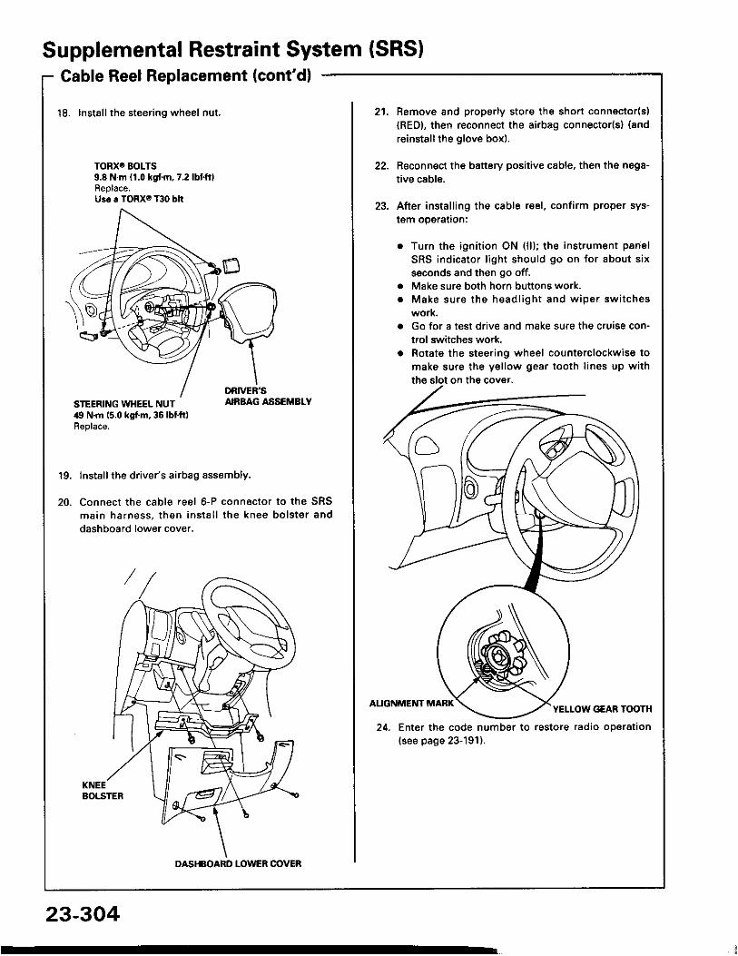
18. Installthe steering wheel nut.
TORXO BOLTS9.8 N.m (1.0 kgf.m,7.2lbtf t lReplace.Us6 a TORX6 T30 bit
STEERING WHEEL NUT,19 N.m 15.0 kgt m, 36 lbt ft)Replace.
AIRBAG ASSEMBLY
19.
20.
Install the driver's airbag assembly.
Connect the cable reel 6-P connactor to the SRSmain harness , then ins ta l l the knee bo ls te r anddashboard lower cover.
DASHBOARD LOWER OOVER
21. Remove and properly store the shon connector(s){RED}, then reconnect the airbag connector(s} (andreinstall the glove box).
Reconnect the battery positive cable, then the nega-tive cable.
After install ing the cable reel, confirm proper sys-l€m operalron:
Turn the ignition ON (l l); the instrument panelSRS indicator l ight should go on for about sixssconds and then go off.Make sure both horn buttons work.Make sure the head l igh t and w iper sw i tcheswork.Go for a test drive and make sure the cruise con-trol switches work.Rotate the steering wheel counterclockwise tomake sure the yellow gear tooth l ines up with
22.
23.
aa
24. Enter the code number to restore radio operation(see page 23-191).
23-304
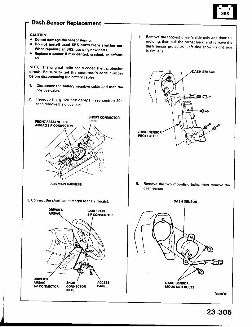
Dash Sensor Replacement
GAUTION:. Oo not drmrgc the sensor wiring.. Do not instrl l used SBS part3 from anothor c!t,
When repairing an SRS: use only new part3.o Roplaco. 3onsor it it is dented, crackod, or doform.
od.
NOTE; The original radio has a coded theft protectionc i rcu i t . 8e sure to ge t the cus tomer ,s code numberbefore disconnecting the b€ttery cabres,
1. Oisconnect the battery negative cable and then theposative cable.
2. Remove the glove box damper (see section 201.then remove the glove box.
SHOBT CONNECTORIREDI
3. Connect the short connector(s) to the airbag(s).
DRIVER'SAIRBAG
DRNEN'SANAAG3.P CONNECTOR
SHORTCONNECTORIREDI
SRS MAIN HARNESS
Remove the footrest driver,s side only and door sil lmolding, then pull the carpet back, and remove thedash sensor protector. (Left side shownj right sideis similar.)
DASHPROTECTOR
5. Remove the two mounting bolts. then remove thedash ssnsor.
(cont'd)
DASH SENSOB
MOUNTIITG BOLTS
23-305
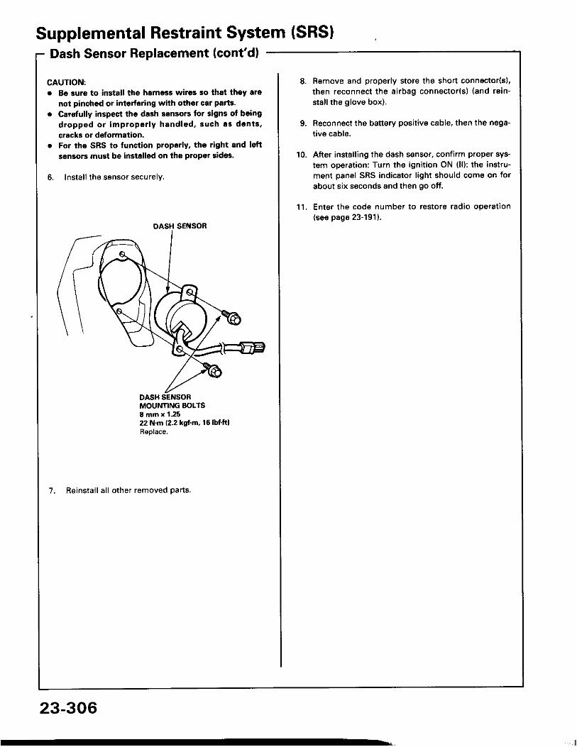
Supplemental Restraint System (SRSIDash Sensor Replacement (cont'dl
CAUTION:. Be 3ure to install the harness wires so that theY ars
not pinchcd or interfering with othor car parte.o Carefully inspest the dash sensors lor signs of boing
dropped or improper ly hand led ,3uch as dents ,cracks or dsformation.
. For the SRS to lunction propotly, ths right and lsftsensors must be installsd on the propor sidos.
6. Install the sensor securely.
DASH SENSOR
MOUNTING BOLTS8 mm x 1.2522 N.m (2.2 kgf.m, 16lbfftlReplace.
7. Reinstall all other removed parts.
23-306
li
10.
Remove and properly store the short connector{sl,then reconnect the airbag connector(s) (and rsin-stallthe glove box).
Reconnect the battery positive cable, then the nega-tive cable.
After installing the dash sensor, confirm proper sys-tem operation: Turn the ignition ON (l l): the instru-ment panel SRS indicator l ight should come on forabout six seconds and then go off.
Enter the code number to restore radio operation(see page 23-191)-
1 1 .
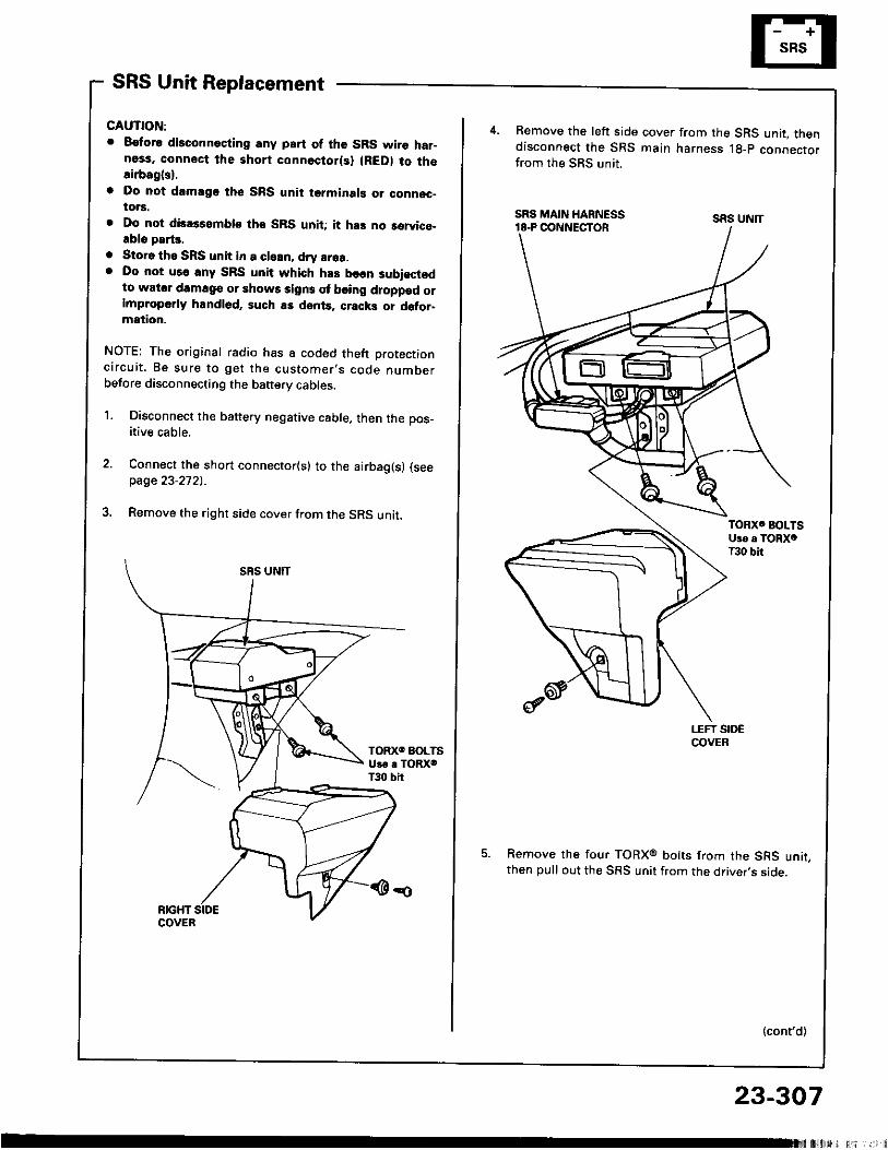
SRS Unit Replacement
CAUTION:. 8€tor6 disconneciing any part of the SRS wire har-
ness, connect the short connectorlsl (RED) to thosirbagl3).
o Do nol drmsgo thc SRS unit terminal! o. connoc-to.s.
. Do not disassemblo tho SRS unit; it ha3 no rervico-.blo parts.
. Storo tho SRS unit in a cleln, dry srea.
. Do not us€ lny SRS unit which h.s been subisctodto wator damag€ or shows sign3 ol b€ing droppad orimproperly handl6d, such as dents. cracki or d6tor-mation.
NOTE: The original radio has a coded theft protectionc i rcu i t . Be sure to ge t the cus tomer ,s code numberbefore disconnecting the baftery cables.
1. Disconnect the battery negative cable, then the pos_itive cable.
Connect the short connector(s) to the airbag(s) (seepage 23-2721.
Remove the right side cover from the SRS unit.
4 . Remove the left side cover from the SRS unit. thendisconnect the SRS main harness lg-p connectorfrom the SRS unit.
Remove the four TORXo bolts from the SRS unit,then pull out the SRS unit from the driver,s side.
(cont'd)
SRS UNIT
23-307
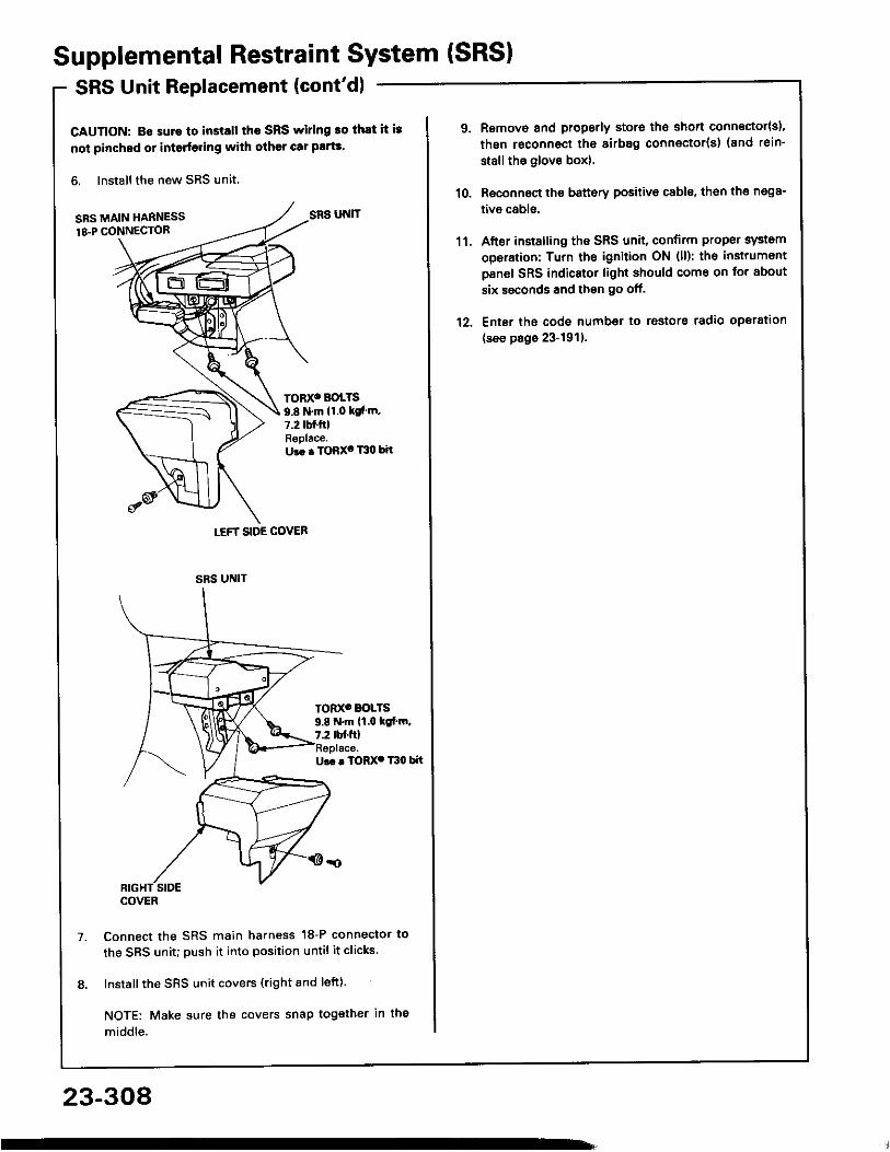
Supplemental Restraint System {SRSISRS Unit Replacement (cont'd)
CAUTION: B€ suro to install tho SRS wiring ro thlt it i3not pinched or interfeling with other car plrts.
6. Install the new SRS unit,
SRS MAIN HARNESS18.P CONN€CTOR
Ur. . TORX. T30 bit
Connect the SRS main harness 18-P connector tothe SRS unit; push it into position unti l i t cl icks.
Install the SRS unit covers (right and left).
NOTE: Make sure the covers snap tog€ther in themiddle.
LEFT SIDE COVER
SRS UNIT
TORX' BOLTS9.8 N.m 11.0 ksl'm.7.2 tbf.ftlReplace.U.. . TORX' T30 bit
TOD(' BOLTS9.8 N.m (1.0 tc[.m,7.2 tbf.ftl
SRS UNIT
COVER
23-308
1' l.
12.
Remove and properly storo the short connector{s),thgn roconnect the sirb8g connector(s) (and rein-st8ll tho glove box).
Roconnoct the battery positivo cable, th€n the n€98-tivo cabls.
After installing the SRS unit, confirm proper systemoperation: Turn the ignition ON (ll): th€ instrumontpanel SRS indicator light should come on for aboutsix ssconds and then go off.
Ent6r tho code number to rostors radio operation(see page 23-191).


![Software Requirement Specifications (SRS)dslab.konkuk.ac.kr/Class/2020/20GP2/Projects/SRS/[T7]SRS.pdf · 2020-08-03 · Software Requirement Specifications (SRS) MediChA.I.n Ver](https://img.pdfslide.net/doc/110x75/5fa5ba6413e3056901461222/software-requirement-specifications-srsdslab-t7srspdf-2020-08-03-software.jpg)