Embed Size (px)
Citation preview

Supplemental Visual Impact Assessment Memorandum
To: David Lee District Local Assistance Engineer California Department of Transportation, District 8, Planning and Local Assistance 464 West 4th Street, 6th Floor (MS-760) San Bernardino, CA 92401-1400
From: Jennifer Ban, PLA, Senior Visual Resource Specialist, ICF
Brian Calvert, Project Director, ICF
Date: March 9, 2018
File: Project File – Mount Vernon Avenue Bridge Project 08-SBD-Mount Vernon Avenue Federal Project Number: BRLS-6507(003) EA: 965120
Subject: Supplemental Visual Impact Assessment Memorandum, ,
This memorandum addresses potential impacts on visual resources from the Mount Vernon Avenue Bridge Replacement Project. The San Bernardino County Transportation Agency (SBCTA), in cooperation with California Department of Transportation (Caltrans), is proposing to replace the existing Mount Vernon Avenue Bridge (Bridge Number 54C-066) over the Burlington Northern Santa Fe (BNSF) rail yard in the City of San Bernardino, San Bernardino County, California.
Preparation of a Visual Impact Assessment Memorandum (VIAM) for the project was originally completed and approved in June 2009 (Caltrans 2009). A National Environmental Policy Act (NEPA) Finding of No Significant Impact (FONSI) was adopted for the project in June 2011 (Caltrans 2011). The project, which involves a road/railroad grade separation, is statutorily exempt from the California Environmental Quality Act (CEQA). Since the NEPA document was adopted, it has been noted that additional project improvements/refinements are needed that were not included in the 2009 VIAM and adopted 2011 NEPA document. The project and these additional improvements are discussed in detail in the following sections.
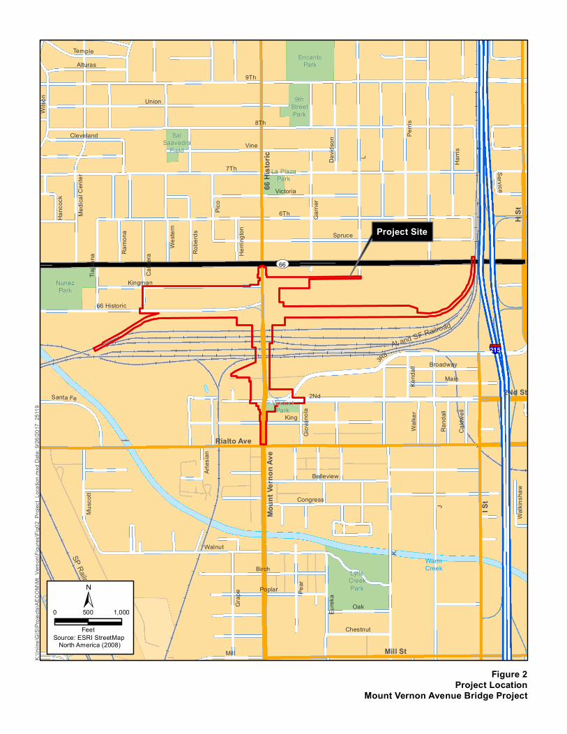
Project Setting The project would occur at Mount Vernon Avenue Bridge in the City of San Bernardino, San Bernardino County, California (Figures 1 and 2) (54C-066), in Section 7, Township 1 South, and Range 4 West on the U.S. Geological Survey San Bernardino South 7.5-minute quadrangle map. The

Supplemental Visual Impact Assessment Memorandum for the Mount Vernon Avenue Bridge Project Page 2 of 8
project setting has remained largely unchanged since the VIAM was adopted in 2009 and the NEPA FONSI was adopted in 2011. The study area is relatively flat and open, with minimal vegetation. Adjacent urban development and the BNSF Railroad Intermodal Facility buildings and tracks create an urban environment with mostly paved surfaces and minimal open areas that support landscaping or ruderal vegetation. Scenic vista views are available from the existing Mount Vernon Avenue Bridge to the surrounding mountain ranges in the background when not obscured by atmospheric haze. However, the foreground views associated with the vistas are dominated by the industrialized landscape associated with the rail facilities, vertical utility poles, and a BNSF smokestack. The bridge itself is most visible in areas west of the project site because of the slightly elevated topography, minimal development, and sparse vegetation. Areas southeast of the project site have the most limited views because of dense residential and commercial development, topography, and heavy vegetation. Views of the bridge are relatively unobstructed from the eastern and western ends of the rail yard.
Land uses in the study area include industrial, commercial, residential, and public facilities. The majority of the study area incorporates the industrial uses surrounding and within the BNSF rail yard. A Metrolink station, parking facilities, and a historical Atchison, Topeka, & Santa Fe passenger and freight depot is adjacent to the project site, within the southeast quadrant of the study area. Commercial uses are situated along Mount Vernon Avenue and 5th Street, north of the rail yard, between Mount Vernon Avenue and Interstate 215. Residential areas are located mainly within the northwest, northeast, and southeast quadrants of the study area, with a small pocket of residential uses within the southwest quadrant. Public facilities near the study area include Lytle Creek Wash and Channel and Nunez Park, which are west of the project site, and La Plaza Park, which is adjacent to Mount Vernon Avenue and north of the project site.
The primary visual change since the 2009 VIAM and 2011 NEPA document is a two-story parking garage, which is now located between West 2nd and 3rd Streets and between Mount Vernon Avenue and Metrolink Way. In addition, south of the West 4th Street cul-de-sac, the location of one crane repair lift has been shifted. One additional crane has been added so that two crane repair lifts are visible from Kingman Street instead of one. Lastly, the west side of the 500 block of Mount Vernon Avenue, north of the BNSF rail yard and between Route 66 and Spruce Street, has undergone redevelopment, including an ampm gas station, which has improved the quality of views along this portion of Mount Vernon Avenue by replacing poorly maintained buildings with well-maintained structures and site landscaping.
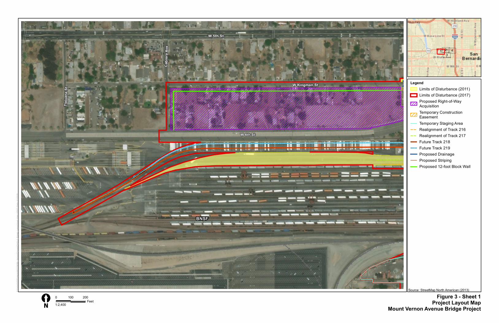
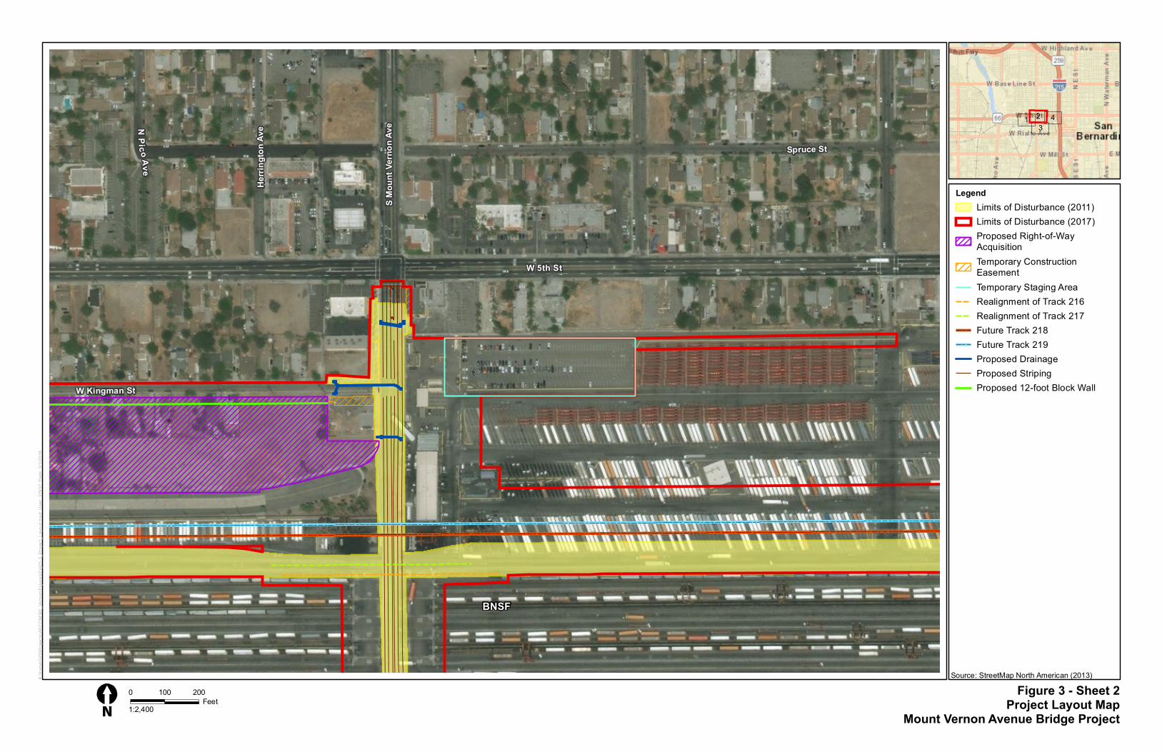
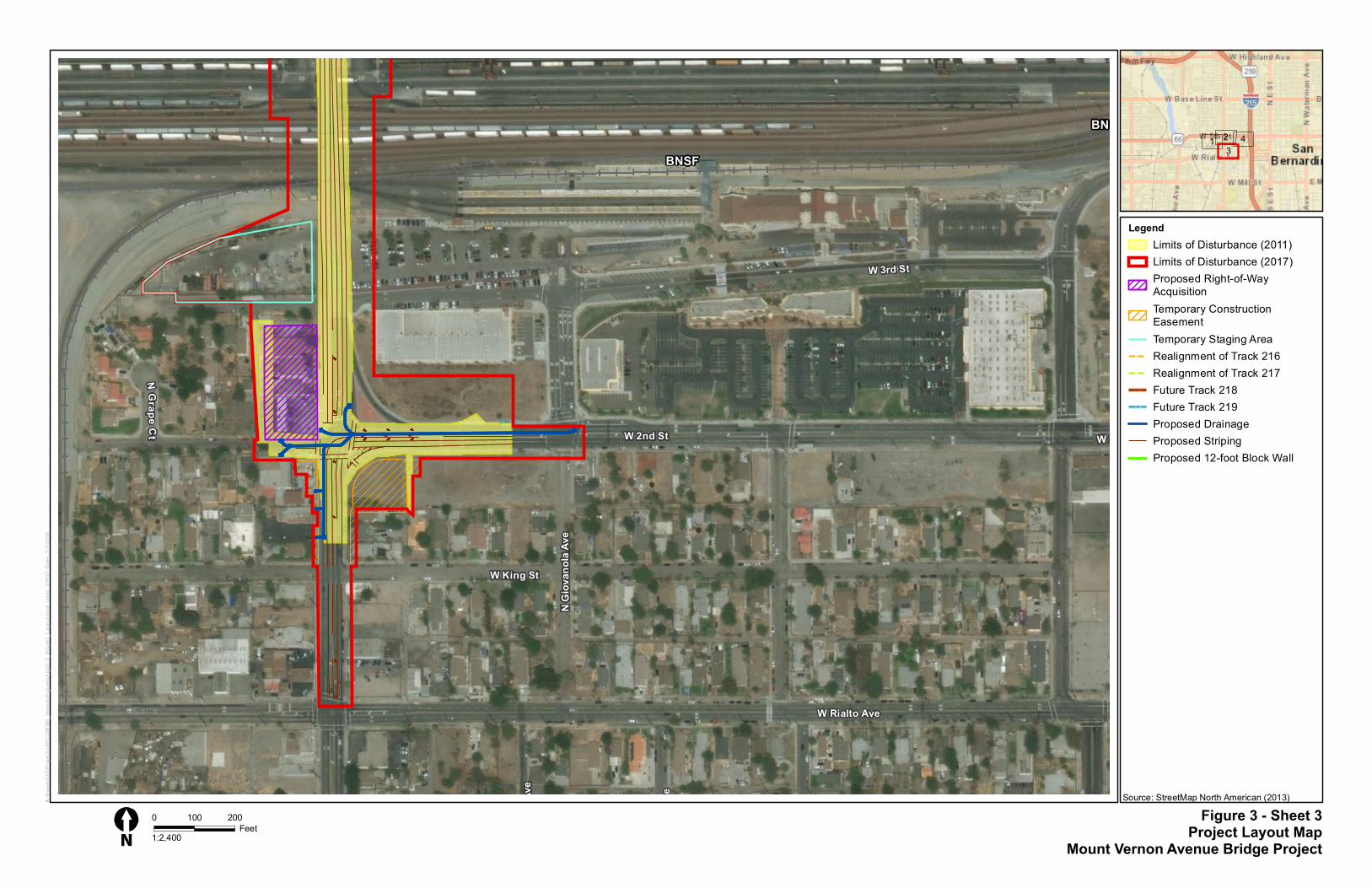
Project Effects The Preferred Alternative (Alternative 3 – Bridge Replacement) identified in the adopted NEPA document extended from just south of 5th Street to just north of Kingman Street. Given the identified project improvements/refinements, the project would now extend from just south of 5th Street to Rialto Avenue (see Figure 3).
The proposed project would result in the following improvements/refinements:
A portion of the BNSF intermodal operations/parking area east of the bridge, on the north side of the existing tracks, would be removed, and a new paved area between Kingman Street and West 4th Street from Cabrera Avenue to Mount Vernon Avenue would be constructed (this would involve acquisition and removal of existing residences/businesses within these limits). A

Supplemental Visual Impact Assessment Memorandum for the Mount Vernon Avenue Bridge Project Page 3 of 8
12-foot-tall block wall and a 20-foot-wide landscape buffer would be constructed along Kingman Street and Cabrera Avenue to shield this area from surrounding uses.
Just west of Mount Vernon Avenue, West 4th Street will form an intersection with Cabrera Avenue.
The existing Eagle Building and four associated buildings would be relocated from the east side of Mount Vernon Avenue to the west side of Mount Vernon Avenue.
The two existing crane repair pads would be relocated north of their current location (one on either side of Mount Vernon Avenue).
Temporary Tracks 218 identified in the adopted NEPA document, would now be a permanent rail track. A new permanent track (Track 219) would be constructed.
Tracks 216 and 217 would be realigned in the immediate vicinity of the new bridge.
The structures at the southwest end of the bridge, bordered by Mount Vernon Avenue to the east, the alley behind the structures to the west, West 3rd Street to the north, and West 2nd Street to the south, would be acquired and removed.
The access associated with structures fronting Mount Vernon Avenue south of West 2nd Street and north of Kingman Street would be reconstructed as needed to match the new road/sidewalk grade.
Consistent with the updated project layout, the following would be incorporated:
Utilities would be relocated as needed to accommodate the proposed improvements.
Best management practices for water quality treatment would be provided as part of the proposed project where feasible.
Signage would be incorporated within the project’s limits of disturbance where necessary.
Pedestrian facilities would be compliant with Americans with Disabilities Act standards.
Geotechnical borings would be conducted within the project’s limits of disturbance as needed for the design of the project.
Temporary advanced signage would be required during construction, which would involve portable changeable message signs or other temporary signage that would not require ground disturbance.
As described in the 2009 VIAM and 2011 NEPA document, no state or local scenic routes would be affected by the proposed project; this is consistent with the current proposed changes. Many of these changes would not result in notable changes to the visual landscape.
Relocating the Eagle Building and ancillary buildings to the east side of Mount Vernon Avenue; the two existing crane repair pads north of their current location, on the west side of Mount Vernon Avenue; and utility lines to accommodate proposed improvements would only shift the location of existing features in the visual landscape and would not add or remove any features. Realignment of Tracks 216 and 217 would occur along an existing vehicular travel way in the rail yard. Permanent Tracks 218 and 219 would be built in areas that are currently used for freight storage. These areas are in proximity to the existing tracks and would not result in a notable change to the visual

Supplemental Visual Impact Assessment Memorandum for the Mount Vernon Avenue Bridge Project Page 4 of 8
landscape. The historic depot is south of where Tracks 218 and 219 would be built and outside the 2017 limits of disturbance. Views from the depot toward Tracks 218 and 219 would be available when rail cars are not parked on the sidings. Views from the depot would not be affected by the proposed changes because the new tracks would not stand out within the existing setting, an area where there are already many tracks within view.
Reconstructing street access along both sides of Mount Vernon Avenue to match the new road/sidewalk grades between West 2nd Street and Kingman Street would require temporary easements for construction and staging, which would result in minor changes to the visual landscape if landscaping and site features such as fencing, retaining walls, or mailboxes are affected. Access along both sides of Mount Vernon Avenue would need to be reconstructed to comply with Deputy Directive-64-R1, Complete Streets - Integrating the Transportation System, which directs that projects provide for the safety and mobility needs of all users with legal access to a transportation facility; implement current design standards that meet the needs of bicyclists, pedestrians, and transit users; and ensure that bicycle, pedestrian, and transit travel elements are included in plans (Caltrans 2008). Implementation of Avoidance and Minimization Measure VIS-1 would relocate or replace affected landscaping, fencing, and other landscape features to the degree possible, reducing visual impacts. In addition, Avoidance and Minimization Measure VIS-2 would ensure that staging areas would be screened from residences, minimizing the amount of visual disruption caused by construction staging.
It is anticipated that project construction would begin in the fall of 2019 and be completed by the fall of 2021. Project construction would occur year-round. In addition, the potential exists for some nighttime construction to occur. This would create the need for high-intensity lighting. However, such lighting would not result in adverse impacts at most locations because residential receptors, which have high viewer sensitivity, would be some distance away or not within sight of the construction area. Furthermore, roadway travelers would be exposed to such lighting very briefly as they pass by. However, if construction activities occur at night in locations that are directly adjacent to residences, then this lighting could shine into residences and disturb residents in their homes. Implementation of Avoidance and Minimization Measures VIS-3 and VIS-4 would ensure that nighttime construction would not occur directly adjacent to residences and that the construction contractor would minimize project-related light and glare to the maximum extent feasible during nighttime construction activities.
The only notable visual change resulting from the proposed improvements/refinements would be related to the acquisition and removal of existing residences and businesses located northwest of the rail yard on the block bordered by Kingman Street, West 4th Street, Cabrera Avenue, and Mount Vernon Avenue and southwest of the rail yard on a half block bordered by Mount Vernon Avenue, an alley behind the structures, West 3rd Street, and West 2nd Street. The removals on the block located northwest of the rail yard would accommodate the proposed BNSF intermodal operations area, which would include a 12-foot-high block wall and a 20-foot-wide landscape buffer along Cabrera Avenue and Kingman Street to obstruct views of the area from adjacent residential locations. The removal of residential dwellings and businesses on the northwest block would expand the view of facilities associated with the rail yard in the vicinity. However, many of the affected parcels are vacant lots with little aesthetic value. The remainder of the affected parcels are occupied properties with residential or small business uses. Many of the occupied properties have well-kept structures and landscaping. However, some of the occupied properties show signs of years of deferred maintenance, with buildings and site features (e.g., fencing, parking areas) that are deteriorated. The properties have degraded visual conditions and little or no landscaping. Similarly, the properties on

Supplemental Visual Impact Assessment Memorandum for the Mount Vernon Avenue Bridge Project Page 5 of 8
the southwest half of the block range from being well kept to poorly repaired. The existing visual conditions on the affected blocks are the same as on the surrounding blocks. The removal of residences and businesses on the northwest block and southwest half block would not greatly alter the visual character of the study area because rail facilities and local roadways already dominate the landscape. The conversion of these blocks constitutes a relatively small expansion compared with the overall scale of the existing facilities. However, residential and commercial receptors would see these changes and would most likely view them negatively. The 12-foot-high block wall and 20-foot-wide landscape buffer along Kingman Street and Cabrera Avenue would improve project aesthetics by providing a vegetative buffer and visual relief from the rail yard for adjacent residents. However, the block wall would introduce a tall, stark vertical surface that detracts from the visual landscape if not properly designed, especially until the landscape buffer matures. In addition, the flat wall surface could be used for graffiti, which would further detract from and degrade views. Similarly, if not properly designed, the proposed landscape buffer may not achieve the desired effect to screen the wall and improve aesthetics. Implementation of Avoidance and Minimization Measures VIS-5 and VIS-7 would ensure that the wall is designed with aesthetic considerations and that the landscape buffer achieves intended goals to improve project aesthetics and wall screening.
Conclusion There would be no substantial impacts on scenic highways, scenic vistas, or eligible or listed historic structures beyond the changes described in the 2009 VIAM and 2011 NEPA document. Project construction activities would result in only temporary visual changes, lasting no longer than approximately 2.5 years, which would not negatively affect viewers. The removal of residences and businesses would most likely be perceived negatively by remaining residents, but the proposed 12-foot-high block wall and 20-foot-wide landscape buffer would provide aesthetic relief for adjacent viewers by blocking views of the rail yard. Implementation of the avoidance and minimization measures would ensure that project impacts would be minimized.
Avoidance, Minimization, and/or Mitigation Measures Avoidance, minimization, and/or mitigation measures have been identified to ensure that visual impacts are minimized. This section provides additional avoidance and/or minimization measures to address specific visual impacts, beyond those specified in the 2009 VIAM and 2011 NEPA document. These will be designed and implemented with concurrence from the District Landscape Architect. The following measures to avoid or minimize visual impacts will be incorporated into the project:
VIS-1 Replace or Relocate Site Features and Landscaping Affected by the Project. Landscaping and related appurtenances (e.g., fencing, driveway gates, similar features) associated with private properties that are unaffected by relocations will be relocated or replaced where appropriate to the degree possible to reduce visual impacts.
VIS-2 Install Visual Barriers between Construction Work Areas and Residential Receptors. Residential receptors have high viewer sensitivity. Therefore, the contractor shall install and maintain temporary visual barriers to obstruct undesirable views of construction activities for residential viewersthat are located directly adjacent to or abutting the construction site. The visual barrier may be chain link fencing with privacy slats, fencing with windscreen material, wood, or other similar barriers. The visual barrier shall be a minimum of six feet high to help maintain the privacy of residents and block ground-level views toward

Supplemental Visual Impact Assessment Memorandum for the Mount Vernon Avenue Bridge Project Page 6 of 8
construction activities. Although this visual barrier would introduce a visual intrusion, it would greatly reduce visual effects associated with visible construction activities and screen construction staging areas where the protection of privacy is deemed desirable.
VIS-3 Limit Construction Directly Adjacent to Residences to Daylight Hours. Construction activities that are located directly adjacent to residences will not take place before or past daylight hours (which vary according to season). This would reduce the amount of construction experienced by residential viewers, because most construction activities would occur during business hours (when most residents are at work), and eliminate the need to introduce high-wattage lighting sources to operate in the dark near residences during construction.
VIS-4 Minimize Fugitive Light from Portable Sources Used for Construction. The construction contractor shall minimize project-related light and glare to the maximum extent feasible, given safety considerations. Color-corrected halide lights will be used. Portable lights will be operated at the lowest allowable wattage and height. For construction occurring on the ground, portable lights will be raised to a height no greater than 20 feet. All lights will be screened and directed downward, toward work activities, and away from the night sky and nearby residents to the maximum extent possible. The number of nighttime lights used will be minimized to the greatest extent possible.
VIS-5 Apply Aesthetic Design Treatments to Wall. Aesthetic design treatments shall be applied to the block wall located along Cabrera Avenue and Kingman Street. Design of the block wall shall evaluate similar, local structures with historic value or that are well-designed and be developed to match and transition to the Mt. Vernon Avenue Streetscape Design Guidelines, detailed within the City’s Paseo Las Placitas Specific Plan and EIR for the Mt. Vernon Corridor plan document from 1992, to ensure that the wall does not create further visual discordance in the landscape. Following the Mt. Vernon Avenue Streetscape Design Guidelines, the wall shall implement aesthetic design features such as mimicking natural material (e.g., stone or rock surfacing) or architectural stylings (e.g., stucco or plaster over adobe brick) and integral color to reduce visibility and to better blend with the landscape. Wall color will be chosen from the Paseo Las Placitas Specific Plan and EIR for the Mt. Vernon Corridor. If the color selection is between 2 or 3 colors, then it is suggested that one of the darker shades be selected. Choosing a shade that is darker will allow the surface to recede and blend within the visual landscape whereas lighter colors advance and are more apparent within the visual landscape. Aesthetic treatments for the wall will be submitted to the Caltrans District 8, District Landscape Architect for review and approval. Regardless of the design treatment applied, SBCTA or its contractor will inspect the wall quarterly and perform graffiti abatement to avoid creating a visual nuisance. However, if notified that graffiti is present, graffiti abatement will occur within one week of being notified.
VIS-6 Apply Best Management Practices to the Landscaping Plan. Vegetative accents and screening will be installed to aid in a perceived reduction in the scale and mass of the block wall along Cabrera Avenue and Kingman Street, while accentuating the design treatment that will be applied to the wall surface (refer to Measure VIS-5). Plant selection will be based on its ability to screen the wall and provide aesthetic accents and will include evergreen and deciduous tree and shrub species that would provide multi layering, seasonal variety, and be visually pleasing to improve aesthetics. The design shall be developed to match and transition to the Mt. Vernon Avenue Streetscape Design Guidelines detailed
Supplemental Visual Impact Assessment Memorandum for the Mount Vernon Avenue Bridge Project Page 7 of 8
within the City’s Paseo Las Placitas Specific Plan and EIR for the Mt. Vernon Corridor plan document from 1992. Plant species will be selected from the plant palette identified within the Landscape Materials section of the Paseo Las Placitas Specific Plan and EIR for the Mt. Vernon Corridor. The landscaping plan will be submitted to the Caltrans District 8, District Landscape Architect for review and approval. Under no circumstances will any invasive plant species be used at any location. Vegetation shall be planted within the first six months following Project completion. An irrigation and maintenance program shall be implemented during the plant establishment period. The irrigation and maintenance program will be submitted to the Caltrans District 8, District Landscape Architect for review and approval.
VIS-7: : The aesthetic treatments for the new wall and buffer area in the northwest quadrant of the project site will be developed through workshops and coordination with San Bernardino County Transportation Authority, Caltrans District 8, District Landscape Architect and the City of San Bernardino
In addition to the measures listed above, mitigation measures MOA CR-6 through MOA CR-8 identified in the 2011 Memorandum of Agreement between Caltrans and the California State Historic Preservation Officer are still applicable and include additional design and landscape requirements for the replacement of the Mount Vernon Avenue Bridge.
Citations California Department of Transportation. 2008. Deputy Directive DD-64-R1: Complete Streets -
Integrating the Transportation System. Sacramento, CA. October.
California Department of Transportation. 2009. Visual Impact Memorandum – Mount Vernon Avenue Bridge Project, City of San Bernardino, Caltrans District 8. San Bernardino, CA. June.
California Department of Transportation. 2011. Mount Vernon Avenue Bridge Project, Environmental Assessment and Programmatic Section 4(f) Evaluation. June.

Supplemental Visual Impact Assessment Memorandum for the Mount Vernon Avenue Bridge Project Page 8 of 8
Attachments
Figure 1, Regional Vicinity Map Figure 2, Project Location Map Figure 3, Project Layout Map

_̂
Project Location
Rivers i
de Canal
Gage
Cana
l
Cable Creek
City Creek
Flood Contro l Channe l
San Timoteo Wash
Highland Canal
Little
San d
Creek
Springbrook Wash
Cab leCr
eek
Chan
nel
Warm Creek
S tra wberr yCr ee
kSa
ndCr
eekEa
stTw
in
Creek
R i v e r s i d eR i v e r s i d eC o u n t yC o u n t y
S a nS a nB e r n a r d i n oB e r n a r d i n o
C o u n t yC o u n t y
ST18ST206
ST18
ST66
ST259
ST60
ST206
ST210
§̈¦210
§̈¦215
§̈¦10
Figure 1Regional Vicinity Map
Mount Vernon Avenue Bridge Project
±Source: ESRI StreetMap
North America (2010)
0 1 20.5
Miles
San Bernardino
Riverside
ImperialSan Diego
Orange
Los Angeles
Kern
P a c i f i cO c e a n
USAMEXICO
Ventura
K:\Irv
ine\G
IS\P
rojec
ts\AE
COM\
Mt_V
ernon
\Figu
res\Fi
g01_
Regio
nal_V
icinit
y.mxd
Date
: 6/22
/2017
251
19
Lytle Creek Channel
WarmWarmCreekCreek
NunezNunezParkPark
EncantoEncantoParkPark
SalSalSaavedraSaavedra
FieldField
La PlazaLa PlazaParkPark
9th9thStreetStreetParkPark
LytleLytleCreekCreekParkPark
ViaductViaductParkPark
SP Railroad
At and SF Railroad
Walke
r
JRa
ndall
Caldw
ellKing
Santa Fe
Birch
Main
Giov
anola
Ser vi ceHa
ncoc
k
Artes
ian
Walki
nsha
w
David
son
I
Robe
rds
Ramo
na
Herrin
gton
Kend
all
Oak
Chestnut
Mill
Pico
Broadway
Cleveland
AlturasTemple
Pear
Wilso
n
Tiajua
na
Cabre
ra
Weste
rn
Eurek
a
Grap
e
Musc
ott
Poplar
Garne
r
Harris
Belleview
Congress
Victoria
Kingman
Vine
Perris
K
Walnut
66 Historic
Medic
al Ce
nter
L
Union
Spruce
3Rd
6Th
9Th
8Th
2Nd
7Th
2Nd St
Moun
t Ver
non A
ve
I St
H St
66 H
istor
ic
Mill St
Rialto Ave
UV66
§̈¦215
Figure 2Project Location
Mount Vernon Avenue Bridge Project
K:\Irv
ine\G
IS\P
rojec
ts\AE
COM\
Mt_V
ernon
\Figu
res\Fi
g02_
Proje
ct_Lo
catio
n.mxd
Date
: 9/26
/2017
251
19
±Source: ESRI StreetMap
North America (2008)
0 1,000500
Feet
Project Site

Pic oA ve
Robe
rds A
ve
Caldw
ell A
ly
Herri
ngton
Ave
Ramo
na Av
e
C a brer
aAve
Weste
rn Av
e
Medic
alCe
nterD
r
T iaj ua
n aSt
L St
Garn
er Av
e
Kend
all Av
e
Parking Lot
Moun
t Vern
onAv
e
66
K St
Jughandle
Driveway
Rialto Ave
2Nd St
3Rd St
215
Musc
ott St
4Th St
Giov
anol a
Ave
I St
Eurek
a Ave
G rapeC t
J St
G St
Waters St
Broadway St
Harri
s St
Perri
s St
Mira
Ln
Main St
HSt
6Th St
Alley
King St
Santa Fe Way
Spruce St
Belleview St
Rand
all Al
y
Walke
r Pl
Kingman St
5Th St
SHEET 1
SHEET 2
SHEET 3
SHEET 4
Figure 3Project Layout Map Sheet Index
Mount Vernon Avenue Bridge Project
K:\Irv
ine\G
IS\Pr
ojects
\AEC
OM\M
t_Vern
on\Fi
gures
\Fig0
1-3_P
rojec
t_Lay
out_i
ndex
.mxd
Date
: 3/1/
2018
379
37
Source: ESRI (2013)
0 400200
Feet
Legend2011 Limits of Disturbance2017 Limits of Disturbance
W 5th St
Tiajua
na St
W 4th St
W Kingman St
Cabr
era Av
e
BNSF
Figure 3 - Sheet 1Project Layout Map
Mount Vernon Avenue Bridge Project
K:\Irv
ine\G
IS\P
rojec
ts\AE
COM\
Mt_V
ernon
\Figu
res\F
ig01-
3_Pr
oject_
Layo
ut.mx
d; Us
er: 37
937;
Date:
3/1/2
018
0 200100Feet
LegendLimits of Disturbance (2011)Limits of Disturbance (2017)Proposed Right-of-WayAcquisitionTemporary ConstructionEasementTemporary Staging AreaRealignment of Track 216Realignment of Track 217Future Track 218Future Track 219Proposed DrainageProposed StripingProposed 12-foot Block Wall
Source: StreetMap North American (2013)
1 23
4
1:2,400N
S Mou
nt Ve
rnon
AveN
P icoAv e
Herri
ngton
Ave
W Kingman St
Spruce St
BNSF
W 5th St
Figure 3 - Sheet 2Project Layout Map
Mount Vernon Avenue Bridge Project
K:\Irv
ine\G
IS\P
rojec
ts\AE
COM\
Mt_V
ernon
\Figu
res\F
ig01-
3_Pr
oject_
Layo
ut.mx
d; Us
er: 37
937;
Date:
3/1/2
018
0 200100Feet
LegendLimits of Disturbance (2011)Limits of Disturbance (2017)Proposed Right-of-WayAcquisitionTemporary ConstructionEasementTemporary Staging AreaRealignment of Track 216Realignment of Track 217Future Track 218Future Track 219Proposed DrainageProposed StripingProposed 12-foot Block Wall
Source: StreetMap North American (2013)
1 23
4
1:2,400N
W Rialto Ave
NGrap eCt
SGiov
anola
Ave
SEur
ekaA
ve
N Giov
anola
Ave
W King St
W 2nd St
W 3rd St
BNSF
BNSF
W 2nd St
Figure 3 - Sheet 3Project Layout Map
Mount Vernon Avenue Bridge Project
K:\Irv
ine\G
IS\P
rojec
ts\AE
COM\
Mt_V
ernon
\Figu
res\F
ig01-
3_Pr
oject_
Layo
ut.mx
d; Us
er: 37
937;
Date:
3/1/2
018
0 200100Feet
LegendLimits of Disturbance (2011)Limits of Disturbance (2017)Proposed Right-of-WayAcquisitionTemporary ConstructionEasementTemporary Staging AreaRealignment of Track 216Realignment of Track 217Future Track 218Future Track 219Proposed DrainageProposed StripingProposed 12-foot Block Wall
Source: StreetMap North American (2013)
1 23
4
1:2,400N

Spruce St
BNSF
Figure 3 - Sheet 4Project Layout Map
Mount Vernon Avenue Bridge Project
K:\Irv
ine\G
IS\P
rojec
ts\AE
COM\
Mt_V
ernon
\Figu
res\F
ig01-
3_Pr
oject_
Layo
ut.mx
d; Us
er: 37
937;
Date:
3/1/2
018
0 200100Feet
LegendLimits of Disturbance (2011)Limits of Disturbance (2017)Proposed Right-of-WayAcquisitionTemporary ConstructionEasementTemporary Staging AreaRealignment of Track 216Realignment of Track 217Future Track 218Future Track 219Proposed DrainageProposed StripingProposed 12-foot Block Wall
Source: StreetMap North American (2013)
1 23
4
1:2,400N


![Untitled-1 [abodethehomes.com]abodethehomes.com/pdf/Zen-Residences-Brochure.pdf · 2018-10-20 · ZEN RESIDENCES The Zen Residences pread over vast, lush green splendor, The Zen Residences](https://img.pdfslide.net/doc/110x75/5f3754dc86c050386263410f/untitled-1-2018-10-20-zen-residences-the-zen-residences-pread-over-vast-lush.jpg)