Embed Size (px)
Citation preview
Supplementary Information:
New High-Energy-Density GeTe-Based Anodes for Li-Ion Batteries
Ki-Hun Nam,‡a Geon-Kyu Sung,‡a Jeong-Hee Choi,⁎b Jong-Sang Youn,c Ki-Joon Jeon,⁎c and
Cheol-Min Park⁎a
a School of Materials Science and Engineering, Kumoh National Institute of Technology, 61
Daehak-ro, Gumi, Gyeongbuk 39177, Republic of Korea. E-mail:[email protected]; Fax:
+82-54-478-7769; Tel: +82-54-478-7746
b Battery Research Center, Korea Electrotechnology Research Institute, 12 Boolmosan-ro,
Changwon, Gyeongnam 51543, Republic of Korea. E-mail: [email protected]; Fax: +82-55-
280-1590; Tel: +82-55-280-1367
c Department of Environmental Engineering, Inha University, 100 Inha-ro, Nam-gu, Incheon
22212, Republic of Korea. E-mail: [email protected]; Tel: +82-32-860-7509
‡K.-H. Nam and G.-K. Sung contributed equally to this work.
1
Electronic Supplementary Material (ESI) for Journal of Materials Chemistry A.This journal is © The Royal Society of Chemistry 2019

1. Morphology and electrochemical behaviors of bulk– and nanocrystalline–Ge.
To examine the contribution of Ge in the GeTe, ball-milled Ge (BM–Ge) was prepared using a
BM for 6 h with bulk–Ge powder. The XRD, SEM image, and particle size distribution analysis
confirmed that the bulk–Ge has tens of micron-sized Ge particles (Figure S1a and b) with a well-
developed cubic crystalline structure (S.G. Fd3m, a=5.657 Å, Figure S1a and b) and the BM–Ge
has several micron-sized Ge particles, which is composed of agglomerated Ge nanocrystallites
(~16 nm, estimated by the Scherrer eq., Figure S1c and d). Figure S1e and f compare the
electrochemical behaviors of bulk– and nanocrystalline–Ge (prepared by BM) particles for LIBs.
The bulk– and nanocrystalline–Ge electrodes showed similar high initial Li-insertion capacities
(1393 mA h g−1 for bulk–Ge and 1429 mA h g−1 for nanocrystalline–Ge, Figure S1e and f.
However, the reversible capacities of the bulk– and nanocrystalline–Ge decreased to 148 mA h g−1
and 205 mA h g−1 after 10 cycles. The poor capacity retention of the Ge was caused by the large
volume change that occurred during the formation of the Li3.75Ge phase.
2
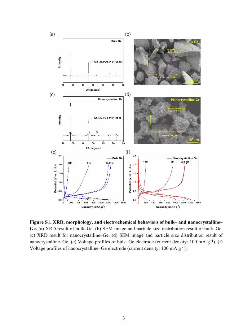
Figure S1. XRD, morphology, and electrochemical behaviors of bulk– and nanocrystalline–Ge. (a) XRD result of bulk–Ge. (b) SEM image and particle size distribution result of bulk–Ge. (c) XRD result for nanocrystalline–Ge. (d) SEM image and particle size distribution result of nanocrystalline–Ge. (e) Voltage profiles of bulk–Ge electrode (current density: 100 mA g−1). (f) Voltage profiles of nanocrystalline–Ge electrode (current density: 100 mA g -1).
3
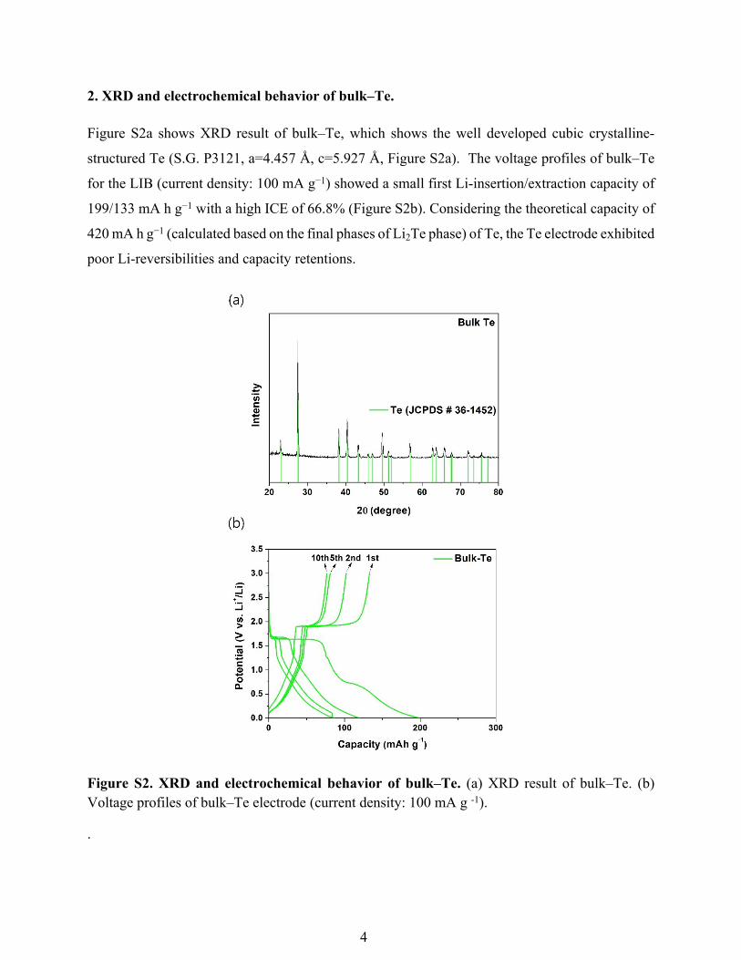
2. XRD and electrochemical behavior of bulk–Te.
Figure S2a shows XRD result of bulk–Te, which shows the well developed cubic crystalline-
structured Te (S.G. P3121, a=4.457 Å, c=5.927 Å, Figure S2a). The voltage profiles of bulk–Te
for the LIB (current density: 100 mA g−1) showed a small first Li-insertion/extraction capacity of
199/133 mA h g−1 with a high ICE of 66.8% (Figure S2b). Considering the theoretical capacity of
420 mA h g−1 (calculated based on the final phases of Li2Te phase) of Te, the Te electrode exhibited
poor Li-reversibilities and capacity retentions.
Figure S2. XRD and electrochemical behavior of bulk–Te. (a) XRD result of bulk–Te. (b) Voltage profiles of bulk–Te electrode (current density: 100 mA g -1).
.
4
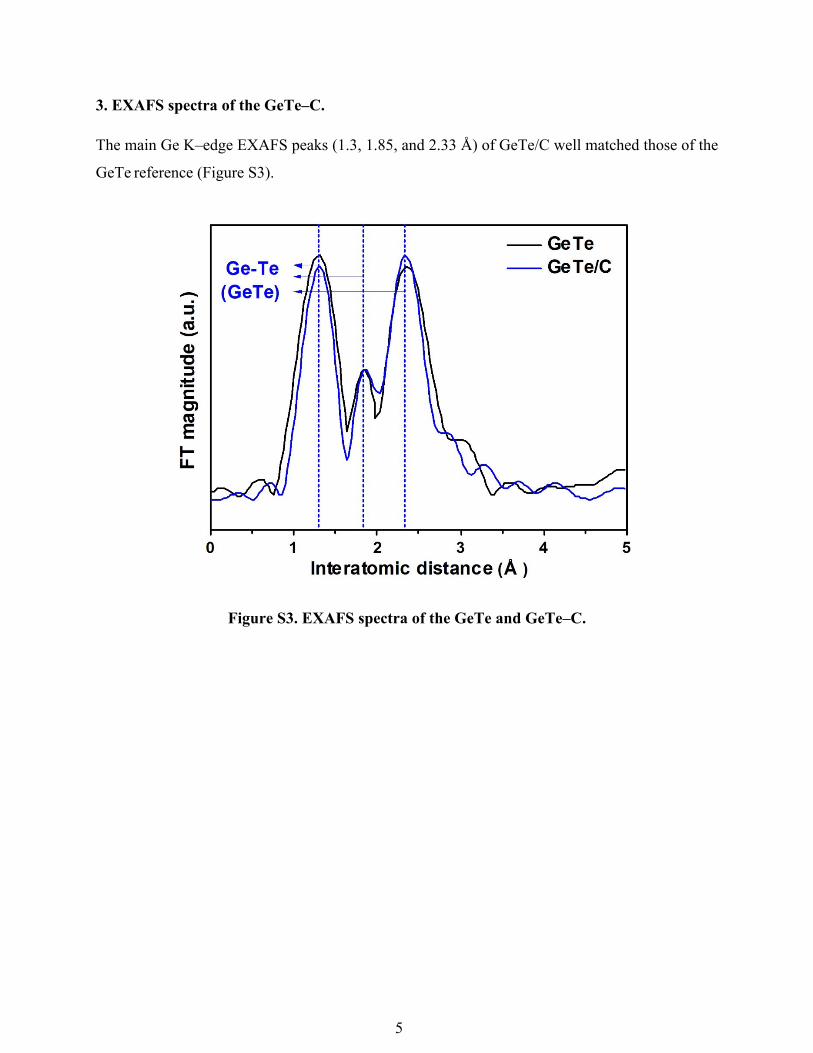
3. EXAFS spectra of the GeTe–C.
The main Ge K–edge EXAFS peaks (1.3, 1.85, and 2.33 Å) of GeTe/C well matched those of the
GeTe reference (Figure S3).
Figure S3. EXAFS spectra of the GeTe and GeTe–C.
5

4. Morphological characteristics of GeTe−C.
Figure S4 shows the SEM image with a particle size distribution result for the synthesized
GeTe−C, which confirms that its average particle size was approximately 6.6 µm.
Figure S4. SEM image with a particle size distribution result of GeTe−C.
6
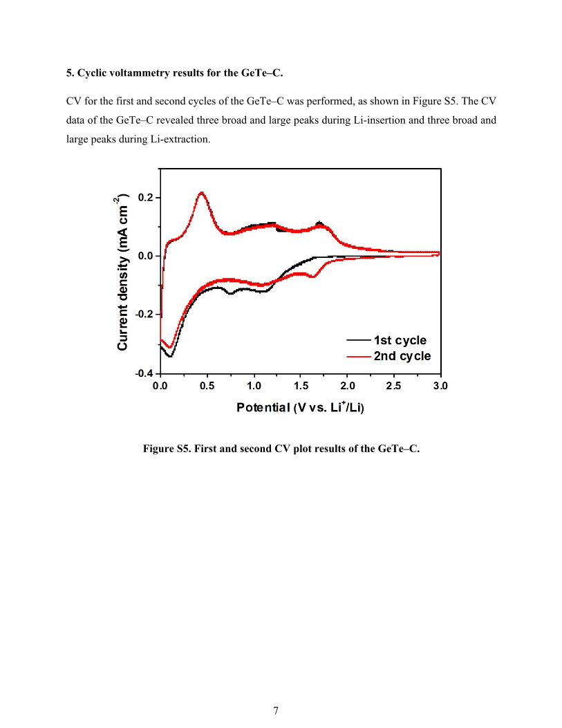
5. Cyclic voltammetry results for the GeTe–C.
CV for the first and second cycles of the GeTe–C was performed, as shown in Figure S5. The CV
data of the GeTe–C revealed three broad and large peaks during Li-insertion and three broad and
large peaks during Li-extraction.
Figure S5. First and second CV plot results of the GeTe–C.
7

6. Ex situ XRD results of the GeTe–C during the Li-insertion/extraction.
Ex situ XRD results of the GeTe–C during Li-insertion/extraction were performed based on the
dQ/dV plot, and the results are shown in Figure S6. However, all the ex situ XRD peaks during
Li-insertion/extraction were amorphized.
Figure S6. Ex situ XRD results of the GeTe–C during the first cycle.
8
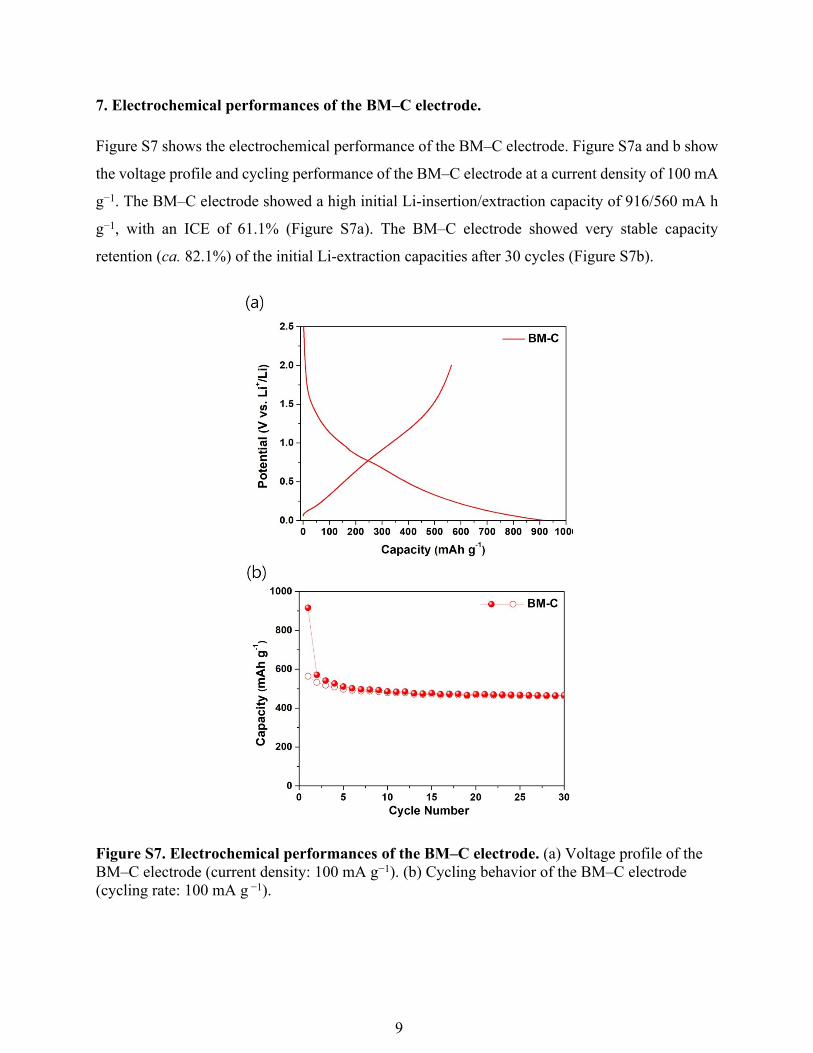
7. Electrochemical performances of the BM–C electrode.
Figure S7 shows the electrochemical performance of the BM–C electrode. Figure S7a and b show
the voltage profile and cycling performance of the BM–C electrode at a current density of 100 mA
g−1. The BM–C electrode showed a high initial Li-insertion/extraction capacity of 916/560 mA h
g−1, with an ICE of 61.1% (Figure S7a). The BM–C electrode showed very stable capacity
retention (ca. 82.1%) of the initial Li-extraction capacities after 30 cycles (Figure S7b).
Figure S7. Electrochemical performances of the BM–C electrode. (a) Voltage profile of the BM–C electrode (current density: 100 mA g−1). (b) Cycling behavior of the BM–C electrode (cycling rate: 100 mA g −1).
9

8. XRD and electrochemical behaviors of the Ge–C and Te–C.
Ge–C and Te–C composites were fabricated by BM processing for 6 h using the bulk–Ge, –Te,
and carbon black powders, respectively and their corresponding XRD results are shown in Figure
S8a and c. Figure S8b and d compares the electrochemical performance results of Ge–C and Te–
C. The Ge–C and Te–C showed high first Li-insertion/extraction capacities of 1218/1030 mA h
g−1 with a high ICE of 84.6% and 551/399 mA h g−1 with a high ICE of 72.4%, respectively.
Figure S8. XRD and electrochemical behaviors of the Ge–C and Te–C. (a) XRD result of Ge–C. (b) Voltage profile of Ge–C electrode (current density: 100 mA g−1). (c) XRD result of Te–C. (d) Voltage profile of Te–C electrode (current density: 100 mA g−1).
10

9. Comparison of the gravimetric capacities of the GeTe–C at various C-rates.
The rate-capability of the GeTe–C as a function of the C-rate (1C represents the full use of the
restricted first Li-extracted capacity in 1 h, 690 mA h g−1) was shown in Figure S9. Highly
reversible capacities at rapid C-rates were observed: 597, 548, and 448 mA h g−1 at 1, 2, and 3C.
The rapid C-rate capabilities were achieved by the formation of small GeTe nanocrystallites in the
amorphous-C matrix through the BM process and repeated Li-insertion/extraction reactions during
cycling, which resulted in shorter Li-ion diffusion paths.
Figure S9. Rate capabilities of GeTe–C (1C–690 mA h g−1) at various C-rates.
11

10. Electrochemical behavior of the full cell (GeTe–C/LCO).
To examine the practical potential of GeTe–C anode, a full cell was fabricated with LCO cathode
and as-prepared GeTe–C anode, and its suitability was tested with 2.0–4.0 V at 0.1 C-rate (1C-
reate = 150 mA g-1), whose result is shown in Figure S10. The full cell was designed with
negative/positive (N/P) ratio of 1.1 based on the loading levels (cathode = 12.129 mg cm-2, anode
= 2.943 mg cm-2). Before the first cycle, the cell was conducted on pre-formation process for stable
solid electrolyte interface (SEI) layer at 0.05 C. The full cell showed a relatively high areal capacity
of ~ 1.2 mA h cm-2 with an appropriated voltage range of 2.0–4.0 V.
Figure S10. Voltage profiles of the full cell with GeTe–C anode and LCO cathode within
the potential range of 2.0–4.0 V at 0.1 C-rate (=15 mA g-1).
12