Embed Size (px)
Citation preview
Manual 0295
Supply & Planning Manual
Updated:
17/01/2019 © Energex 2019
Page:
1 of 222
SUPPLY & PLANNING MANUAL
TABLE OF CONTENTS
Section 1.0: Introduction
Section 2.0: Supply
Section 3.0: Planning
Section 4.0: Power Quality
Manual 0295
Supply & Planning Manual
Updated:
17/01/2019 © Energex 2019
Page:
2 of 222
TABLE OF CONTENTS
1 INTRODUCTION ..................................................................................................................... 7
1.1 POLICY .......................................................................................................................... 7
1.2 SCOPE ........................................................................................................................... 7
1.3 PHILOSOPHY ................................................................................................................ 7
1.4 POLICY REVIEW ........................................................................................................... 7
2 SUPPLY .................................................................................................................................. 8
2.1 CUSTOMERS’ INSTALLATIONS AND SERVICE LINES .............................................. 8
2.2 NATIONAL ENERGY CUSTOMER FRAMEWORK ........................................................ 8 2.2.1 Large Customer Connection Process .................................................................. 9 2.2.2 Connection charges for Alternative Control Services (ACS) ................................. 9 2.2.3 Capital contributions for Standard Control Services (SCS) .................................. 9 2.2.4 Pioneer schemes ................................................................................................. 9
2.3 GENERAL COMMERCIAL CONDITIONS OF SUPPLY ............................................... 11 2.3.1 Categories Of Supply Conditions ....................................................................... 11 2.3.2 Obligation To Connect ....................................................................................... 11 2.3.3 Capital Contributions – General ......................................................................... 12 2.3.4 Asset Removal or Supply Abolishment Involving Substation Assets on
Customer Premises ........................................................................................... 13
2.4 SUPPLY TO CUSTOMER EXTENSIONS ..................................................................... 14 2.4.1 Responsibilities Of Customer ............................................................................. 14 2.4.2 Procedure for Supply to Customer Extensions ................................................... 14
2.5 SUPPLY TO RESIDENTIAL, COMMERCIAL & INDUSTRIAL SUBDIVISIONS ........... 15
2.6 SUPPLY TO RURAL SUBDIVISIONS .......................................................................... 16 2.6.1 General .............................................................................................................. 16
2.7 SUPPLY TO HIGH VOLTAGE CUSTOMERS .............................................................. 17 2.7.1 High Voltage Customer ...................................................................................... 17 2.7.2 Supply at High Voltage ...................................................................................... 17 2.7.3 Joint Ownership of HV Switchboard ................................................................... 17 2.7.4 Responsibility for Operation of a Customer's High Voltage Installation .............. 18 2.7.5 Maintenance of Equipment ................................................................................ 18 2.7.6 Metering ............................................................................................................ 18 2.7.7 Consumers Terminals and Service Lines ........................................................... 19 2.7.8 Approval of Equipment ...................................................................................... 19 2.7.9 Communication with Customer .......................................................................... 19 2.7.10 Conditions for Supply at High Voltage ............................................................... 19 2.7.11 Determination of the Sale Price for the Sale of Existing Energex Assets ........... 21
2.8 CUSTOMER GROUPS ................................................................................................. 22
2.9 UNMETERED SUPPLY ................................................................................................ 23 2.9.1 Unmetered Supply to Customer’s Non-Standard Equipment ............................. 23 2.9.2 Cable TV Power Supply Units ............................................................................ 28
Manual 0295
Supply & Planning Manual
Updated:
17/01/2019 © Energex 2019
Page:
3 of 222
2.10 TEMPORARY SUPPLY ................................................................................................ 32 2.10.1 Minor Temporary Supply ................................................................................... 32 2.10.2 Major Temporary Supply ................................................................................... 32
2.11 QUALITY OF SUPPLY ................................................................................................. 33 2.11.1 Introduction ........................................................................................................ 33 2.11.2 Sensitive Loads ................................................................................................. 33 2.11.3 Disturbing Loads ................................................................................................ 34 2.11.4 Further Information/Customer Assistance .......................................................... 34
2.12 SECURITY OF RIGHT OF WAY – WAYLEAVES AND EASEMENTS ......................... 35 2.12.1 Security Of Right Of Way – Wayleaves and Easements .................................... 35 2.12.2 Transformer and Ring Main Unit Sites ............................................................... 40 2.12.3 Aboriginal Cultural Heritage ............................................................................... 41 2.12.4 Native Title ........................................................................................................ 41
2.13 SUPPLY ARRANGEMENTS ........................................................................................ 42 2.13.1 Provision of Ground Transformer Stations – Loads Exceeding 100 kVA
(Electricity Regulation 2006). ............................................................................. 42 2.13.2 Provision of Underground Service within Existing Overhead Area ..................... 43 2.13.3 Extension of 11 kV Mains On to Private Property (Other Than Farms) –
Existing Mains along The Roadway ................................................................... 45 2.13.4 Extension of 11 kV or LV Mains to Private Property (Other Than Farms) –
Existing Mains on Private Property .................................................................... 45 2.13.5 Positioning of Energex Assets in Rural and Semi Urban Areas ......................... 45 2.13.6 Minimum Cost Procedures for the Assessment of Charges to Customers ......... 46 2.13.7 Minimum Design Standards – Overhead Mains Extensions ............................... 47 2.13.8 Distribution Network Plant Deferral Policy .......................................................... 48
2.14 SMALL SCALE RENEWABLE ENERGY GENERATION INTERCONNECTED WITH Energex SUPPLY ........................................................................................................ 48
2.15 RELOCATION AND/OR UNDERGROUNDING OF EXISTING OVERHEAD ASSETS 49 2.15.1 General .............................................................................................................. 49 2.15.2 Powerline Undergrounding and Re-engineering Policy ...................................... 49
2.16 FOOTPATH JOINT USE COST SHARING ARRANGEMENT ...................................... 53 2.16.1 Joint Use Trench Installations ............................................................................ 53 2.16.2 Joint Use Directional Boring ............................................................................... 53 2.16.3 Joint Use Layout/Conduit Arrangements ............................................................ 53
3 PLANNING ............................................................................................................................ 59
3.1 LOAD CONTROL ......................................................................................................... 59 3.1.1 Introduction ........................................................................................................ 59 3.1.2 Signal Systems .................................................................................................. 61 3.1.3 The System ....................................................................................................... 63
3.2 SUPPLY TO LARGE INSTALLATIONS ....................................................................... 72 3.2.1 Introduction ........................................................................................................ 72 3.2.2 Application for Supply ........................................................................................ 74 3.2.3 Size and Nature Of The Load ............................................................................ 74 3.2.4 Methods of Supplying Load From The Network ................................................. 75 3.2.5 Establishing Distribution Substations On Customers' Premises ......................... 77 3.2.6 Types of Substation ........................................................................................... 77 3.2.7 The Economics of Supply to Large Installations ................................................. 83
Manual 0295
Supply & Planning Manual
Updated:
17/01/2019 © Energex 2019
Page:
4 of 222
3.2.8 Form of Agreement ............................................................................................ 83 APPENDIX 3.2.A - ESTIMATING MAXIMUM DEMANDS OF LARGE
INSTALLATIONS ............................................................................................... 85 APPENDIX 3.2.B - ESTIMATION OF THE LOAD FACTOR .......................................... 92
3.3 LOW VOLTAGE SYSTEM DESIGN AND PLANNING ................................................. 95 3.3.1 Introduction ........................................................................................................ 95 3.3.2 Background ....................................................................................................... 95 3.3.3 Allowable Voltage Drop ................................................................................... 107 3.3.4 Voltage Management – Issues On Distribution Substations and Low Voltage
Networks ......................................................................................................... 110 3.3.5 Process for the Connection of New Low Voltage Loads ................................... 115 APPENDIX3.3.A - LOW VOLTAGE CONDUCTOR AND CABLE IMPEDANCES ....... 117
3.4 GUIDELINES FOR SIZING OF DISTRIBUTION TRANSFORMERS .......................... 118 3.4.1 General Design Principles ............................................................................... 118 3.4.2 Calculation of Transformer Sizing .................................................................... 119 3.4.3 Customer Categories ....................................................................................... 122
3.5 LOW VOLTAGE TIE POLICY FOR SUBDIVISIONS .................................................. 124 3.5.1 Introduction ...................................................................................................... 124 3.5.2 Criteria for Economic Feasibility....................................................................... 125 3.5.3 Criteria for Technical Feasibility ....................................................................... 126
3.6 LOW VOLTAGE SERVICES ...................................................................................... 127 3.6.1 General ............................................................................................................ 127 3.6.2 Maximum Demand........................................................................................... 127 3.6.3 Effect on Distribution Transformer ................................................................... 129 3.6.4 Effect on Voltage Conditions ............................................................................ 129 3.6.5 Solar PV and Batteries .................................................................................... 130 3.6.6 Effect on Other Customers .............................................................................. 131 3.6.7 Preferred Size of Consumer’s Mains ............................................................... 131
3.7 FAULT LEVELS AT DISTRIBUTION SUBSTATIONS ............................................... 132 3.7.1 Background ..................................................................................................... 132 3.7.2 Revised Typical Fault Levels At Distribution Substations ................................. 132 APPENDIX 3.7.A - Maximum LV Fault Current for High Impedance and Low
Impedance Transformers ................................................................................. 133 3.7.3 Reach of Single and Dual LV Fuses ................................................................ 133
3.8 FERRORESONANCE ................................................................................................. 135 3.8.1 Background ..................................................................................................... 135 3.8.2 Typical Situations Where Ferroresonance Can Occur ..................................... 137 3.8.3 Probability of Ferroresonant Overvoltages ....................................................... 138 3.8.4 Methods of Controlling Ferroresonance ........................................................... 139 3.8.5 References ...................................................................................................... 143 APPENDIX 3.8.A - FERRORESONANCE THEORY ................................................. 144 APPENDIX 3.8.B - CRITICAL CABLE LENGTHS FOR IMPERIAL SIZE 11 kV
CABLES .......................................................................................................... 148 APPENDIX 3.8C - LIMITATION OF GANGED DROP OUT FUSE UNITS TO
TRANSFORMERS OF CAPACITY 300 kVA OR LESS ................................... 149
3.9 11 kV TIE POLICY FOR SUBDIVISIONS ................................................................... 150 3.9.1 Introduction ...................................................................................................... 150 3.9.2 General Reliability Standard ............................................................................ 150 3.9.3 Energex HV Feeder Tie Policy ......................................................................... 150
Manual 0295
Supply & Planning Manual
Updated:
17/01/2019 © Energex 2019
Page:
5 of 222
3.9.4 Tie Cable Size Requirements .......................................................................... 153 3.9.5 Practical Application of Tie Policy .................................................................... 154
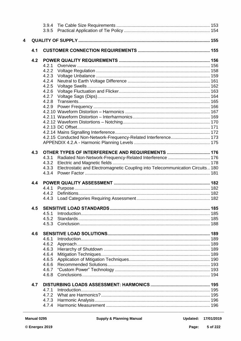
4 QUALITY OF SUPPLY ........................................................................................................ 155
4.1 CUSTOMER CONNECTION REQUIREMENTS ......................................................... 155
4.2 POWER QUALITY REQUIREMENTS ........................................................................ 156 4.2.1 Overview ......................................................................................................... 156 4.2.2 Voltage Regulation .......................................................................................... 158 4.2.3 Voltage Unbalance .......................................................................................... 159 4.2.4 Neutral to Earth Voltage Difference ................................................................. 161 4.2.5 Voltage Swells ................................................................................................. 162 4.2.6 Voltage Fluctuation and Flicker ........................................................................ 163 4.2.7 Voltage Sags (Dips) ......................................................................................... 164 4.2.8 Transients ........................................................................................................ 165 4.2.9 Power Frequency ............................................................................................ 166 4.2.10 Waveform Distortion – Harmonics ................................................................... 167 4.2.11 Waveform Distortion – Interharmonics ............................................................. 169 4.2.12 Waveform Distortions – Notching ..................................................................... 170 4.2.13 DC Offset ......................................................................................................... 171 4.2.14 Mains Signalling Interference ........................................................................... 172 4.2.15 Conducted Non-Network-Frequency-Related Interference............................... 173 APPENDIX 4.2.A - Harmonic Planning Levels ............................................................ 175
4.3 OTHER TYPES OF INTERFERENCE AND REQUIREMENTS .................................. 176 4.3.1 Radiated Non-Network-Frequency-Related Interference ................................. 176 4.3.2 Electric and Magnetic fields ............................................................................. 178 4.3.3 Electrostatic and Electromagnetic Coupling into Telecommunication Circuits .. 180 4.3.4 Power Factor ................................................................................................... 181
4.4 POWER QUALITY ASSESSMENT ............................................................................ 182 4.4.1 Purpose ........................................................................................................... 182 4.4.2 Definitions ........................................................................................................ 182 4.4.3 Load Categories Requiring Assessment .......................................................... 182
4.5 SENSITIVE LOAD STANDARDS ............................................................................... 185 4.5.1 Introduction ...................................................................................................... 185 4.5.2 Standards ........................................................................................................ 185 4.5.3 Conclusion ....................................................................................................... 188
4.6 SENSITIVE LOAD SOLUTIONS ................................................................................. 189 4.6.1 Introduction ...................................................................................................... 189 4.6.2 Approach ......................................................................................................... 189 4.6.3 Hierarchy of Shutdown .................................................................................... 189 4.6.4 Mitigation Techniques ...................................................................................... 189 4.6.5 Application of Mitigation Techniques ................................................................ 190 4.6.6 Recommended Solutions ................................................................................. 193 4.6.7 “Custom Power” Technology ........................................................................... 193 4.6.8 Conclusions ..................................................................................................... 194
4.7 DISTURBING LOADS ASSESSMENT: HARMONICS ............................................... 195 4.7.1 Introduction ...................................................................................................... 195 4.7.2 What are Harmonics? ...................................................................................... 195 4.7.3 Harmonic Analysis ........................................................................................... 196 4.7.4 Harmonic Measurement .................................................................................. 196
Manual 0295
Supply & Planning Manual
Updated:
17/01/2019 © Energex 2019
Page:
6 of 222
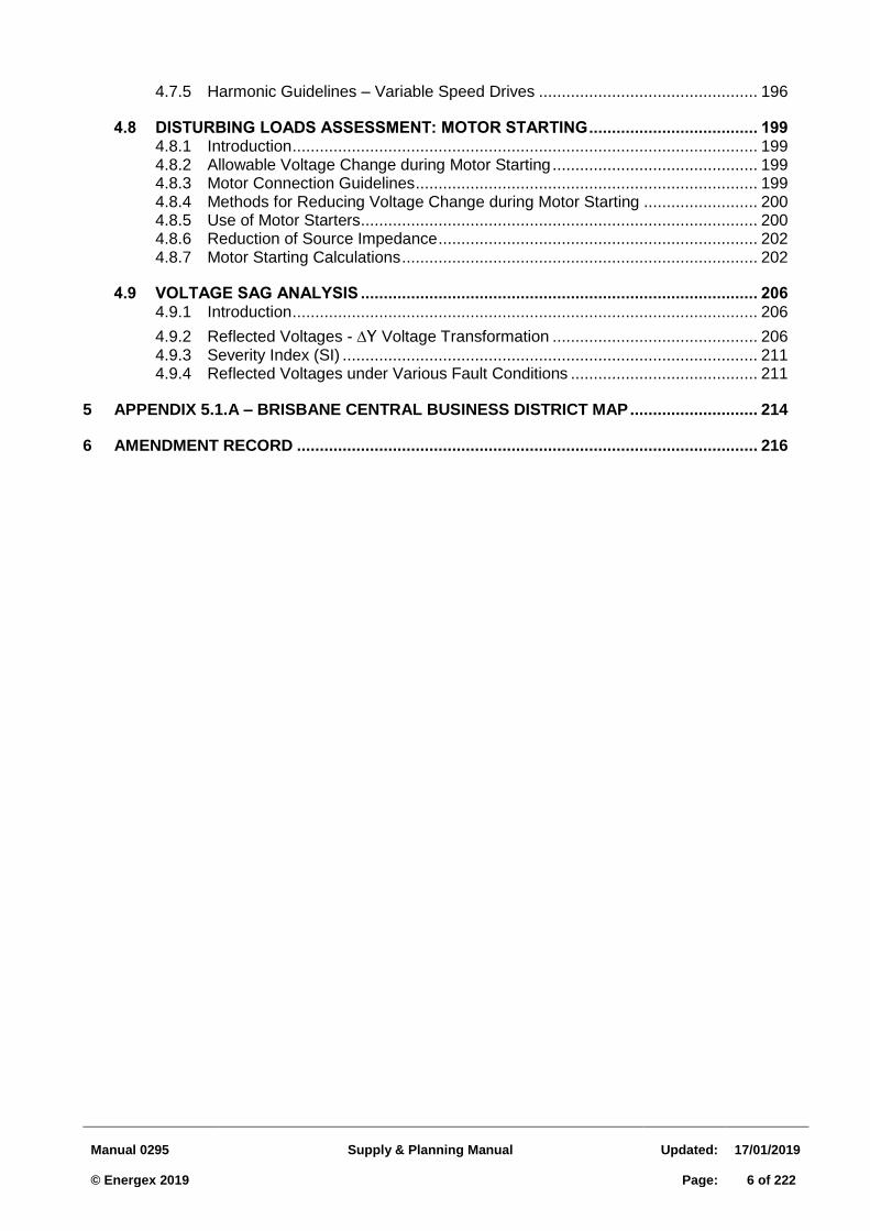
4.7.5 Harmonic Guidelines – Variable Speed Drives ................................................ 196
4.8 DISTURBING LOADS ASSESSMENT: MOTOR STARTING ..................................... 199 4.8.1 Introduction ...................................................................................................... 199 4.8.2 Allowable Voltage Change during Motor Starting ............................................. 199 4.8.3 Motor Connection Guidelines ........................................................................... 199 4.8.4 Methods for Reducing Voltage Change during Motor Starting ......................... 200 4.8.5 Use of Motor Starters ....................................................................................... 200 4.8.6 Reduction of Source Impedance ...................................................................... 202 4.8.7 Motor Starting Calculations .............................................................................. 202
4.9 VOLTAGE SAG ANALYSIS ....................................................................................... 206 4.9.1 Introduction ...................................................................................................... 206
4.9.2 Reflected Voltages - ∆Y Voltage Transformation ............................................. 206 4.9.3 Severity Index (SI) ........................................................................................... 211 4.9.4 Reflected Voltages under Various Fault Conditions ......................................... 211
5 APPENDIX 5.1.A – BRISBANE CENTRAL BUSINESS DISTRICT MAP ............................ 214
6 AMENDMENT RECORD ..................................................................................................... 216
Manual 0295
Supply & Planning Manual
Updated:
17/01/2019 © Energex 2019
Page:
7 of 222
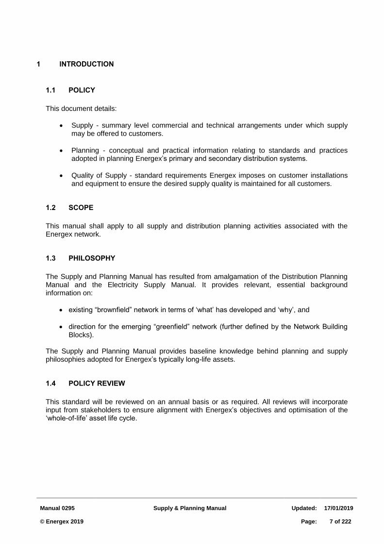
1 INTRODUCTION
1.1 POLICY
This document details:
Supply - summary level commercial and technical arrangements under which supply may be offered to customers.
Planning - conceptual and practical information relating to standards and practices adopted in planning Energex’s primary and secondary distribution systems.
Quality of Supply - standard requirements Energex imposes on customer installations and equipment to ensure the desired supply quality is maintained for all customers.
1.2 SCOPE
This manual shall apply to all supply and distribution planning activities associated with the Energex network.
1.3 PHILOSOPHY
The Supply and Planning Manual has resulted from amalgamation of the Distribution Planning Manual and the Electricity Supply Manual. It provides relevant, essential background information on:
existing “brownfield” network in terms of ‘what’ has developed and ‘why’, and
direction for the emerging “greenfield” network (further defined by the Network Building Blocks).
The Supply and Planning Manual provides baseline knowledge behind planning and supply philosophies adopted for Energex’s typically long-life assets.
1.4 POLICY REVIEW
This standard will be reviewed on an annual basis or as required. All reviews will incorporate input from stakeholders to ensure alignment with Energex’s objectives and optimisation of the ‘whole-of-life’ asset life cycle.
Manual 0295
Supply & Planning Manual
Updated:
17/01/2019 © Energex 2019
Page:
8 of 222
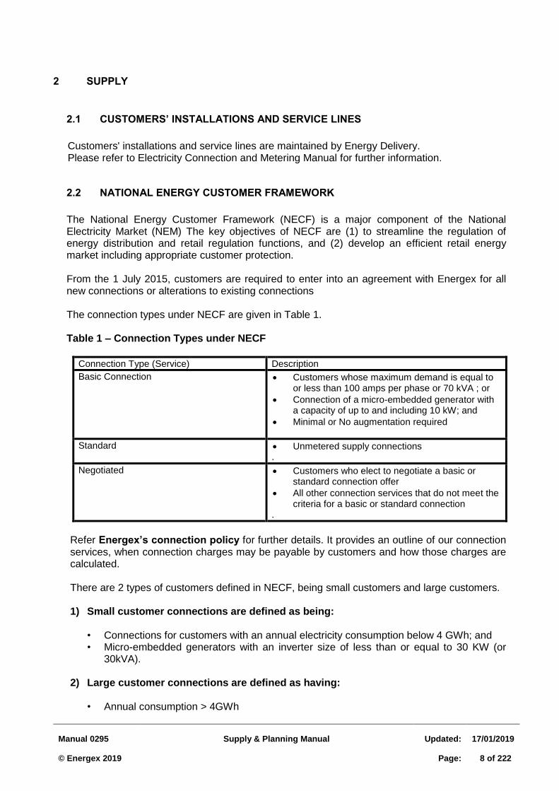
2 SUPPLY
2.1 CUSTOMERS’ INSTALLATIONS AND SERVICE LINES
Customers' installations and service lines are maintained by Energy Delivery. Please refer to Electricity Connection and Metering Manual for further information.
2.2 NATIONAL ENERGY CUSTOMER FRAMEWORK
The National Energy Customer Framework (NECF) is a major component of the National Electricity Market (NEM) The key objectives of NECF are (1) to streamline the regulation of energy distribution and retail regulation functions, and (2) develop an efficient retail energy market including appropriate customer protection. From the 1 July 2015, customers are required to enter into an agreement with Energex for all new connections or alterations to existing connections The connection types under NECF are given in Table 1. Table 1 – Connection Types under NECF
Connection Type (Service) Description
Basic Connection Customers whose maximum demand is equal to or less than 100 amps per phase or 70 kVA ; or
Connection of a micro-embedded generator with a capacity of up to and including 10 kW; and
Minimal or No augmentation required
Standard
Unmetered supply connections .
Negotiated Customers who elect to negotiate a basic or standard connection offer
All other connection services that do not meet the criteria for a basic or standard connection
.
Refer Energex’s connection policy for further details. It provides an outline of our connection services, when connection charges may be payable by customers and how those charges are calculated.
There are 2 types of customers defined in NECF, being small customers and large customers.
1) Small customer connections are defined as being:
• Connections for customers with an annual electricity consumption below 4 GWh; and • Micro-embedded generators with an inverter size of less than or equal to 30 KW (or
30kVA).
2) Large customer connections are defined as having:
• Annual consumption > 4GWh
Manual 0295
Supply & Planning Manual
Updated:
17/01/2019 © Energex 2019
Page:
9 of 222
• Estimated maximum demand > 1MVA • Significant connection assets (i.e. installed capacity for new connection > 1MVA) • Significant HV feeder connection works, annual consumption may be <4GWh • Embedded Generation with capacity > 30 kW (or 30 kVA)
2.2.1 Large Customer Connection Process
A negotiated Connection Contract will apply for Large Customers. The Large Customer Connection process is outlined in RED 00768 and the Customer Standards for Small to Medium Scale Embedded Generators is outlined in RED 00657.
Where a Large Customer does not enter into a negotiation Connection Contract, a deemed connection contract will apply.
2.2.2 Connection charges for Alternative Control Services (ACS)
ACS Customers must pay the full cost of the connection service.
Alternative control services include:
• Connection application services (e.g. negotiating a connection offer, undertaking
planning studies and analysis or performing a protection and power quality assessment)
• Pre-connection consultation services (e.g. customised or site-specific response or preparation of preliminary designs and planning reports)
• Large customer connections, including commissioning and energisation • Subdivision and real estate development connections • Removal of a network constraint for an embedded generator • Temporary connections • Connection alterations
2.2.3 Capital contributions for Standard Control Services (SCS)
Energex may seek a contribution from a customer for the costs of undertaking a SCS (i.e. small customer connections and augmentation of the shared network) if the incremental cost of the connection service exceeds the estimated incremental revenue expected to be derived from the connection service.
A capital contribution may be payable under the following circumstances:
• Augmentation of connection assets and/or network extension assets which are required solely for the benefit of a small customer.
• Augmentation of the shared distribution network for a customer who exceeds the shared network augmentation threshold i.e. customers with a maximum demand of >100 amps per phase (other than non-registered embedded generators and real estate developers) and micro-embedded generators with a capacity of > 5 kW.
2.2.4 Pioneer schemes
There are instances such as an Energex Pioneer scheme where the customer may be entitled to a refund of connection charges. The Pioneer scheme applies if a network extension asset ceases within 7 years after its installation and energisation to be dedicated to the exclusive use of the customer occupying the premises.
Manual 0295
Supply & Planning Manual
Updated:
17/01/2019 © Energex 2019
Page:
10 of 222
When a subsequent customer connects to a network extension which is subject to a Pioneer scheme, Energex will provide each customer already connected to the extension with a refund and charge subsequent customers the amount determined by the Pioneer scheme.
Energex will calculate the charge from a subsequent customer and refund to each customer already connected to an extension by:
Taking into account the length a subsequent customer uses of an extension asset relative to other customers already connected to the extension; or
Taking into account the amount of electricity demand used by a subsequent customer relative to other customers already connected to the extension; and
Depreciating extension assets over 20 years using a straight line depreciation method.
Manual 0295
Supply & Planning Manual
Updated:
17/01/2019 © Energex 2019
Page:
11 of 222
2.3 GENERAL COMMERCIAL CONDITIONS OF SUPPLY
2.3.1 Categories Of Supply Conditions
General categories of conditions, applicable when a customer applies for electricity supply are:
Tariff Conditions Refer to the Energex Network Pricing Schedule for further information.
Agreement Conditions Agreement conditions -as outlined in the NECF (refer Section 2.2)
Temporary Supply Conditions Temporary supply conditions apply to all installations considered to be of a temporary nature – ie likely to be connected for less than 10 years.
2.3.2 Obligation To Connect
In accordance with Electricity Act 1996, section 40D, Energex’s obligation to connect does not apply where:
a) The customer’s connection services application is for supply at a rate more than the
maximum capacity of the connection to the entity’s supply network; b) The customer does not comply with a requirement of the entity to give any of the
following — (i) a reasonable advance payment for customer connection services; (ii) a reasonable security or agreement for security for performing the customer’s
obligations to the entity; (iii) a capital contribution towards the entity’s costs incurred, or to be incurred, in
extending or increasing the capacity of its supply network to provide the services;
c) After disconnecting supply under the Electricity Act 1994 or a connection contract, the entity is not reasonably satisfied the matter that caused the disconnection has been remedied, rectified or fixed;
d) For supply to premises for which there is an existing agreement with the entity for supply
of electricity — (i) the applicant does not agree on similar terms to those that apply for balance of
the term of the existing agreement; and (ii) the entity does not otherwise agree;
e) The customer does not provide and maintain space, equipment, access, facilities or
anything else the customer must provide for the services, under the Electricity Act 1994 or a connection contract;
f) The customer is not a party to a retail contract with a retail entity under which the retail
entity provides customer retail services to the customer’s premises; or g) A regulation provides the obligation does not apply.
Manual 0295
Supply & Planning Manual
Updated:
17/01/2019 © Energex 2019
Page:
12 of 222
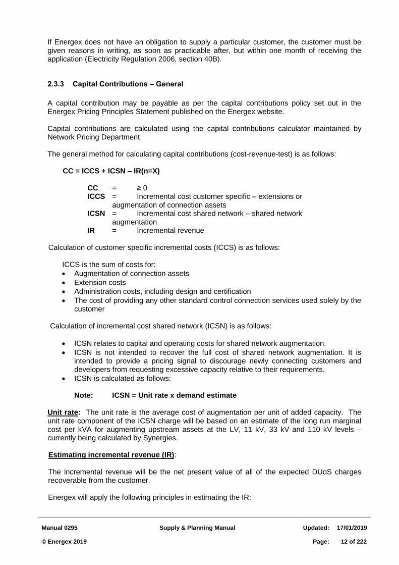
If Energex does not have an obligation to supply a particular customer, the customer must be given reasons in writing, as soon as practicable after, but within one month of receiving the application (Electricity Regulation 2006, section 40B).
2.3.3 Capital Contributions – General
A capital contribution may be payable as per the capital contributions policy set out in the Energex Pricing Principles Statement published on the Energex website.
Capital contributions are calculated using the capital contributions calculator maintained by Network Pricing Department.
The general method for calculating capital contributions (cost-revenue-test) is as follows:
CC = ICCS + ICSN – IR(n=X)
CC = ≥ 0 ICCS = Incremental cost customer specific – extensions or augmentation of connection assets ICSN = Incremental cost shared network – shared network augmentation IR = Incremental revenue
Calculation of customer specific incremental costs (ICCS) is as follows:
ICCS is the sum of costs for:
Augmentation of connection assets
Extension costs
Administration costs, including design and certification
The cost of providing any other standard control connection services used solely by the customer
Calculation of incremental cost shared network (ICSN) is as follows:
ICSN relates to capital and operating costs for shared network augmentation.
ICSN is not intended to recover the full cost of shared network augmentation. It is intended to provide a pricing signal to discourage newly connecting customers and developers from requesting excessive capacity relative to their requirements.
ICSN is calculated as follows: Note: ICSN = Unit rate x demand estimate
Unit rate: The unit rate is the average cost of augmentation per unit of added capacity. The unit rate component of the ICSN charge will be based on an estimate of the long run marginal cost per kVA for augmenting upstream assets at the LV, 11 kV, 33 kV and 110 kV levels – currently being calculated by Synergies.
Estimating incremental revenue (IR):
The incremental revenue will be the net present value of all of the expected DUoS charges recoverable from the customer.
Energex will apply the following principles in estimating the IR:
Manual 0295
Supply & Planning Manual
Updated:
17/01/2019 © Energex 2019
Page:
13 of 222
Forecast DUoS revenue will be based on the price path set out in the AER’s determination for 1 July 2015 to 30 July 2020 for the relevant tariff class. For the period from 1 July 2020, Energex will assume a constant tariff in real terms;
A discount rate based on Energex’s approved regulatory WACC converted to pre-tax terms using the estimated average effective tax rate for the regulatory control period will be applied;
A 30 year discount period will be applied for residential customers;
If the customer is a business customer, then an assumed connection period of 15 years will be applied. However, where a 15 year connection period does not reflect a reasonable estimate of the time that the connection service will be connected, Energex may apply an alternative assumed connection period;
For basic connection offers and where the connection falls below the 100 amps per phase (or 70 kVA) threshold, Energex will exclude from the IR the portion of DUoS charges attributable to augmentation of the shared network; and
Must ensure that operational and maintenance costs have no net impact on the capital contribution payable by the customer.
Security fee
A security fee may be applied to manage the risk associated with Energex not receiving the incremental revenue that was estimated when the connection offer was prepared.
A security fee will generally only be requested where Energex is required to install significant infrastructure to provide electricity supply and will be included in the offer to provide connection services.
The security fee will be held in the form of a bank guarantee Total charges
Total Charges for connection services can be determined as follows:
Connection charges for services classified as ACS
Capital contributions for services classified as SCS
Connection charges for extension assets to which a pioneer scheme applies
Security fees
2.3.4 Asset Removal or Supply Abolishment Involving Substation Assets on Customer Premises
Qld Electricity Regulation 2006 - S62 will only apply in situations where Energex has received a request for removal of the assets and has not received any enquiry or application for the customer’s premises for either a temporary builders supply or new permanent connection.
If Energex has received concurrently a request for asset removal and a new connection enquiry or application for temporary or future permanent supply at a site, the asset removal request shall be treated as an ACS project with all costs fully recoverable from the customer.
In advising the customer of the above requirements, Energex needs to make the customer aware of the lead time requirements for new connections e.g. if a customer initiates an asset removal request and then waits until this is completed before lodging a new connection application, that connection application will be subject to the normal lead times from the date it was submitted.
Manual 0295
Supply & Planning Manual
Updated:
17/01/2019 © Energex 2019
Page:
14 of 222
2.4 SUPPLY TO CUSTOMER EXTENSIONS
This section outlines the basic conditions for providing a supply of electricity where an extension of electricity mains is required.
Note: All network extensions require a review to ensure that the extended network has adequate protection coverage as per current protection standards.
2.4.1 Responsibilities Of Customer
Customer may be required to:
contribute a share to earlier contributors and or current project in accordance with Energex Connection policy
provide Energex with electrical load and site details
provide the correct property description
provide wayleaves or easements (where required)
comply with the conditions of offer including clearing (if required)
provide suitable accommodation for Energex equipment such as cable pits and conduits on the property and appropriate civil works for ground substations.
provide conduits across existing frontages to facilitate underground of existing overhead.
2.4.2 Procedure for Supply to Customer Extensions
Large Customers 2.4.2.1
The Supply for Large Customers shall follow the process outlined in the Large Customer Connection (LCC) Process (RED 00768) and in the Network Service Connection intranet site. The process allows for either Energex to perform the design and construction or to an external party to perform the design and construction. The phases of the LCC process include:
1. Pre-feasibility Connection Enquiry (Form 1001) 2. Connection Enquiry (Form 1593) 3. Connection Application 4. Acceptance of Offer 5. Engagement of a Design Service Provider 6. Engagement of a Construction Service Provider 7. Notification to Energex on completion of project
Small Customers 2.4.2.2
(a) Energex shall design and construct
(b) Energex's estimate shall include:
all reticulation costs (excluding the cost of service and meters)
all switching costs
all Energex clearing costs
all related on costs
Energex shall provide funds towards the capital cost of the extension in accordance with the Energex capital contributions policy.
Manual 0295
Supply & Planning Manual
Updated:
17/01/2019 © Energex 2019
Page:
15 of 222
2.5 SUPPLY TO RESIDENTIAL, COMMERCIAL & INDUSTRIAL SUBDIVISIONS
Refer Energex document: RED 00982 Subdivision Standards – Developer Design and Construct Estates for further details.
Manual 0295
Supply & Planning Manual
Updated:
17/01/2019 © Energex 2019
Page:
16 of 222
2.6 SUPPLY TO RURAL SUBDIVISIONS
2.6.1 General
Rural subdivisions are subdivisions with blocks in excess of 16 hectares. Unlike smaller rural residential and urban subdivisions, councils do not normally require supply agreements as a condition for subdivision approval. In many cases, however, the developer requests that electricity reticulation be provided to enhance the marketing of the subdivision and it is in these circumstances that the following conditions of supply are applicable.
The design of supply to rural subdivisions also differs from other subdivisions. It is very difficult to position transformers to suit future residential sites; in some cases, it may even be necessary to provide an 11 kV extension into private property to suit a future site.
To overcome these difficulties of design and provide simple conditions of supply, the following procedures have been formulated:
(a) Initial design will allow for the provision of a basic 11 kV "backbone" supply to the
subdivision. The design should attempt, as much as possible, to cater for the efficient location of future transformers and extensions.
(b) The developer will be required to make a non-refundable capital contribution to cover
the cost of this 11 kV backbone supply system. (c) Future Energex customers in the subdivision will be required to arrange for their own
individual supply from this backbone system. This will normally involve the provision of low voltage mains and transformers.
(d) Where an 11 kV extension is requested, either internal or external to the subdivision,
this also shall be treated under normal capital contribution conditions. (e) A clear written outline of responsibilities and costs shall be provided to the developer
and future customers to avoid ambiguity and the possibility of future disagreements. (f) All agreements shall be confirmed in writing. (g) Existing consumer’s lines that cross property boundaries as the result of a
subdivision are required to be relocated at the developer’s expense.
Approval may be granted by Energex for the consumer’s line to remain, subject to the developer providing the following:
An easement is to be granted in favour of the affected properties over the point of attachment of the Energex connection, the meter position and the consumers line where any of these are located beyond the property boundary of the allotment they are supplying. The easement is to be a services easement for electricity.
Manual 0295
Supply & Planning Manual
Updated:
17/01/2019 © Energex 2019
Page:
17 of 222
2.7 SUPPLY TO HIGH VOLTAGE CUSTOMERS
2.7.1 High Voltage Customer
Unless there are extenuating circumstances, a HV customer is required to supply and maintain all the high voltage equipment on their installation.
They are metered at high voltage and billed on either a HV tariff or a power purchase agreement via their retailer. For contestable customers refer Customer Connections Manager.
2.7.2 Supply at High Voltage
Energex may agree to make supply available to a customer at high voltage. Conditions of supply at high voltage are set out in the Electricity Regulation 2006.
2.7.3 Joint Ownership of HV Switchboard
Conditions 2.7.3.1
Unless there are extenuating circumstances, new HV customers will not be offered joint ownership of HV switchboards with Energex.
Joint ownership of a high voltage switchboard between Energex and an existing customer will be permitted with the following conditions applying:
(a) The customer will be permitted to purchase part, or all of Energex circuit
breaker equipment and this will become part of the customer's installation and may become the customer's main switch (es).
(b) The customer will be required to pay Energex's present capital value of
equipment, together with a capitalised maintenance amount. Maintenance of the equipment will be undertaken by Energex at no additional cost to the customer.
(c) The customer is to have ready access to the customer's own circuit breakers
to control the customer's own installation. The customer will not be permitted to operate Energex equipment except where special agreement exists.
(d) All equipment under the customer's control is to be labelled by the customer to
Energex's satisfaction. (e) The customer's installation including that purchased from Energex is to comply
with the general requirements of AS3000 Wiring Rules. (f) In the event of the customer's switchgear requiring future major repairs or
replacement due to age or fault damage, it will be the responsibility of the customer to bear the full cost thereof.
Manual 0295
Supply & Planning Manual
Updated:
17/01/2019 © Energex 2019
Page:
18 of 222
Existing customers transferring to HV supply 2.7.3.2
An existing customer transferring to high voltage supply will be permitted to purchase from Energex the existing high voltage equipment required. The customer may elect to install the customer's own equipment and in this case Energex equipment will be removed by Energex. Requests by a customer to transfer to HV supply should be referred to Customer Connections Planning Manager
Some installations still exist where supply is metered at high voltage, but in all other respects the customer takes supply as a low voltage customer. New installations do not qualify for this arrangement.
2.7.4 Responsibility for Operation of a Customer's High Voltage Installation
a) Energex will not operate the customer’s high voltage equipment except in situations where
Energex has a current maintenance contract for the customer’s HV network. In extreme emergencies, Energex may operate customer equipment if it is de-energised, subject to normal safety and risk assessment procedures. In any of the above circumstances when Energex operates customer’s equipment, costs will be recoverable from the customer. Before Energex operates any customer equipment the customer must supply to the relevant Energex switching controller a schematic drawing of the high voltage system indicating the status of all equipment.
b) It will be a condition for Energex agreeing to supply a customer at high voltage that the
customer must have either Energex trained staff or a contractor available who has been trained by Energex as a high voltage operator and who is familiar with the equipment. It will be the responsibility of the customer to notify Energex of the designated operator and of any changes. A register is maintained in Energex Control Centre of all customer representatives who have been trained as high voltage operators.
c) It will be a requirement that before the installation is energised, the customer must have
available on site, safety and operating equipment required for the safe performance of any electrical work on the equipment as required by Electricity Regulation 2006.
2.7.5 Maintenance of Equipment
With the exception of "joint ownership" HV switchboards, all maintenance on the customer's installation is the sole responsibility of the customer.
2.7.6 Metering
Refer to the following document. Queensland Electricity Metering Manual http://corp/egx/red/Published%20Documents/JW%20QLD%20Electricity%20Metering%20Manual.docx
Manual 0295
Supply & Planning Manual
Updated:
17/01/2019 © Energex 2019
Page:
19 of 222
2.7.7 Consumers Terminals and Service Lines
In each high voltage installation, the customer's terminals are to be defined, as this designates the line of responsibility between Energex and the customer. If a service line is provided, Energex will be responsible for the cost of up to 20 metres of overhead or 7 metres of underground service from the customer's property alignment at the point nominated by Energex. The cost of any service in excess of these lengths is to be borne by the customer and is a capital contribution to Energex's cost of supply. The replacement and maintenance of the excess service is the responsibility of Energex.
2.7.8 Approval of Equipment
For statutory requirements of the Electricity Regulation 2006, AS/NZS3000 and compliance with Energex policy; an auditor (accredited in HV inspections) and/or Customer Connections Planning shall be consulted regarding purchase of equipment for a HV customer.
2.7.9 Communication with Customer
In early communication with a customer Energex's requirements must be conveyed regarding operation of equipment and the necessity for the customer to be responsible for their own equipment maintenance.
2.7.10 Conditions for Supply at High Voltage
Cases have arisen where the conversion of existing low voltage supply to high voltage has been sought by a customer with a single LV point of supply where the primary consideration is the reduction in charges to the customer concerned arising from the comparison of relevant HV and LV tariffs. The rate differential between LV and HV is not now sufficient to make this the prime reason for seeking HV supply.
The agreement to provide HV supply should be supported by evidence that HV reticulation within the customer's installation is warranted – eg. Where one or more of the following factors apply:
where HV motors or other equipment are to be installed
where the magnitude and spread of the customer's loading prohibits the use of a customer's LV network alone
where the total capital and operating costs of the customer's LV installation from a single LV point of supply would clearly exceed that of the equivalent HV installation with multiple substations
where HV supply is necessary for mining installations
where there is a reasonable probability of future plant resulting in increased loading for which one of the above would apply
where HV supply would mitigate a quality of supply problem.
Energex's policy concerning the responsibilities and procedures for making supply available to a customer at high voltage or converting an existing low voltage supply to a high voltage supply is as follows:
(a) Definition – "High Voltage Supply" means a supply to a customer's consumers terminals at a voltage in excess of 1000 volts. All works beyond the consumer’s terminals shall be owned and maintained by the customer. "High Voltage Supply" will also include
Manual 0295
Supply & Planning Manual
Updated:
17/01/2019 © Energex 2019
Page:
20 of 222
some existing customers metered at high voltage but not owning all transformers and/or high voltage automatic circuit breakers beyond the consumer’s terminals where such equipment is supplied and maintained by Energex.
(b) Entitlement to HV Supply – A customer who meets Energex conditions is entitled to a
high voltage supply. A customer is required to have a minimum demand of 300 kW and an annual energy usage of 1.0 GWh (per metering point) for Energex to recommend and provide HV supply to a site. For supply under tariff conditions, Energex has no power to require a customer to take supply at high voltage.
(c) Standard Voltages – The standard voltage for supply at high voltage shall be 132 kV,
110 kV, 33 kV and 11 kV. No new customers may be supplied at a high voltage other than a standard high voltage. Provisions for existing customers supplied at a non-standard high voltage are described below.
(d) Substation – Where the high voltage supply to a customer reasonably requires the
provision of a substation on a customer's premises, the customer shall be required to make available, free of cost, suitable space for the substation in accordance with Electricity Regulation 2006, Section 59. Any electric line or equipment installed by Energex may be used for the purpose of giving or maintaining a supply of electricity to customers not within premises as well as those who occupy such premises, provided that the owner of the premises agrees (Electricity Regulation 2006 Section 60(1).
(e) Provision of Substation Building on Customer's Premises – Where Energex requires a
substation to be installed on a customer's premises for the purpose of supplying electricity at high voltage to a customer on such premises, Energex shall determine in consultation with the owner, or the owner's agent an acceptable location and design for the substation and associated electric lines on the premises. The owner shall be responsible for the completion of the substation building in accordance with Energex's requirements before Energex installs the electrical equipment in the substation.
The owner shall be responsible for all costs incurred in the provision and adaptation of the space for the substation and any other building works deemed necessary by Energex to permit the installation of the substation.
In general, no services other than Energex's electric lines and approved parts of the owner's electrical or other works shall pass through, or under, the substation. If the substation is above ground level, or if the services are sleeved, other arrangements may be approved by Energex. Consumer’s mains from Energex's substation shall be supplied and installed by the owner in a manner specified by AS/NZS 3000.
(f) Protection and Isolation of Service Lines – The protection of a high voltage supply
consists of the protective device located at the Energex substation together with control and protective devices which form part of a customer's high voltage electrical installation. Additional protective or control devices may be provided by Energex where appropriate.
(g) Customer's High Voltage Electrical Installation – A customer's high voltage electrical
installation shall comply with the requirements of the Electricity Regulation 2006. The costs of high voltage testing to establish this compliance shall be met by the customer.
(h) Recoverable Costs – Before giving high voltage supply, the owner of the premises shall
pay a fixed amount being the estimated capital cost of electric lines and equipment in excess of that normally provided free by Energex and the estimated capitalised value of operating and maintenance costs incurred by Energex in the provision of such excess electric lines and equipment.
Manual 0295
Supply & Planning Manual
Updated:
17/01/2019 © Energex 2019
Page:
21 of 222
(i) Multiple Supply Points – A customer will normally be given only one service to a high
voltage electrical installation. This requirement does not preclude the provision of more than one high voltage circuit from a single point of supply where a single circuit would not have sufficient capacity to supply the customer's load.
(j) Tariffs – A customer supplied at high voltage is subject to terms and conditions of tariffs
outlined in the Energex Network Pricing Schedule, including which tariff the customer is eligible for.
(k) Supply and Maintenance of Customers' High Voltage Works – Customers supplied at
high voltage as defined in section 2.7.1 are responsible for the supply and maintenance of all high voltage plant and equipment beyond the consumer’s terminals.
(l) Conversion from Low Voltage Supply to High Voltage Supply – When Energex agrees
to a customer upgrade from low voltage to high voltage supply, the customer shall:
purchase existing Energex plant and equipment, evaluated on the basis of the unexpired life using current costs or;
supply and install their own plant and equipment including transformers, switchgear and cables, in order to comply with the policy as outlined above.
Upgraded sites shall comply with all current requirements.
(m) Existing Customers supplied at non-standard High Voltage – Supply at a non-standard
high voltage to existing customers will continue up to an agreed level of maximum demand, which will be defined for each customer. This level will not exceed a demand which can be met when one of Energex's transformers associated with the supply of the non-standard voltage is unserviceable.
Increased supply beyond the agreed maximum demand will be given only at a standard voltage.
2.7.11 Determination of the Sale Price for the Sale of Existing Energex Assets
Contact the Customer Connections Planning Department.
Manual 0295
Supply & Planning Manual
Updated:
17/01/2019 © Energex 2019
Page:
22 of 222
2.8 CUSTOMER GROUPS
To provide the appropriate economic and cost of supply signals, Energex’s network pricing regime distinguishes between different customer groups. Details are provided in Energex’s Network Pricing Principles Statement which is published annually on Energex’s website. The arrangements for making supply available for each customer group is summarised below:
1. Individually Calculated Customers (ICCs) are typically those customers with electricity consumption greater than 40 GWh per year at a single connection point; or where a customer’s circumstances mean that the average shared network charge becomes meaningless or distorted. These customers will be supplied under an individual negotiated connection contract. Refer to the Customer Connections Planning Department for details.
2. Connection Asset Customers (CACs) typically include the non-ICCs with electricity
consumption level greater than 4 GWh per year at a single connection point; or where a customer has a dedicated supply system with significant connection assets. These customers will in most cases be supplied under an individual negotiated connection contract. Refer to the Customer Connections Planning Department for details.
3. Standard Asset Customers (SACs) are generally those customers with annual
electricity consumption below 4 GWh per year, whose supply arrangements are consistent across the customer group. These customers are supplied under general arrangements covered in section 3.2.
Manual 0295
Supply & Planning Manual
Updated:
17/01/2019 © Energex 2019
Page:
23 of 222
2.9 UNMETERED SUPPLY
2.9.1 Unmetered Supply to Customer’s Non-Standard Equipment
General 2.9.1.1
The following is to provide consistency in the method of connection of unmetered supply to Non-Standard customer’s equipment. All unmetered equipment is designated as a Customer’s installation and, as such, must comply with the requirements of the Electricity Regulation 2006, the Electrical Safety Regulation 2002 and AS/NZS 3000 Wiring Rules. (Note: A main switch, circuit protection, MEN and earth electrode must be supplied by the customer for each separate installation). Examples of Customer’s installations suitable for connection to Unmetered Supply:
Bus shelter
Traffic Signals / Signs
Telstra Payphone, RIM, RCM, Broadband etc
Local Council Security Cameras, Flow meters
Street Identity Lights (street names) etc
Specific Shared Asset installations Note: Special conditions apply to Rate 3 Public Lighting installations (refer Energex Public Lighting Construction manual and RED 00576 Standard Conditions for Public Lighting Services). Refer to the Energex Network Price Schedule for conditions and network prices applicable to unmetered supply including streetlights.
Definitions 2.9.1.2
Customer:
The person or company applying for supply via their retailer will be responsible for payment of network charges. These network charges will be levied via the person’s or company’s retailer. Category 1:
An arrangement consisting of the piece of non-standard equipment (ie bus stop shelter), a switchboard, and the consumer’s mains direct from their installation to Energex’s point of supply. The customer shall be responsible for:
The full cost of installation including the consumer’s mains plus any costs incurred by Energex in making supply available (unless otherwise specified in this policy)
Maintenance of the full installation including lamp replacement
Repairs to the installation including the consumers mains
Manual 0295
Supply & Planning Manual
Updated:
17/01/2019 © Energex 2019
Page:
24 of 222
Category 2:
An arrangement consisting of non-standard customer equipment that takes supply via an Energex service direct to the installation at the customer’s expense. In this situation the consumer’s terminals will be the line side of the service fuse and neutral link connection located at the customer’s equipment. This category will only apply where a pit and duct system exists.
The customer shall be responsible for:
The full cost of installation including Energex service mains and associated work
Maintenance of the full installation including lamp replacement but not the Energex service
Repairs to the installation but not including the Energex service Point of Supply:
The customer’s point of supply shall be the load side of Energex’s fuse in most cases. In category 2 situations the fuse will be found in the consumer’s switchboard.
Method of Supply to New or Relocated Unmetered Non-standard Equipment 2.9.1.3
Underground shall always be the preferred method of supply. In some exceptional cases an overhead supply may be allowed. The overhead service will attach to a property pole, which complies with the Energex Electricity Connection and Metering Manual and complies with the statutory requirements across a footpath. Poles shall not be installed on Energex’s underground alignment, they may however be installed on the overhead alignment and clearly identified as the customer’s pole. Customer to seek Local Authority (ie: Local Council or Department of Transport) approval prior to installing a pole on the footpath. Note: The customer is to bear full cost of relocation or rewiring should the supply be undergrounded at a later stage. Supply from an Overhead System (Category 1) Supply via a standard drop down service in accordance with Section 2 of the Overhead Construction Manual and Section 2 page 27 of the Street Light Construction Manual. Alternatively the customer may install a property pole on Energex’s pole alignment as long as the pole is clearly identified as a property pole (ie a plaque shall be erected by the customer on the pole with the customer’s name and contact number). Service checks for underground assets and Council approval for installing poles on the footpath are the responsibility of the customer.
The customer shall pay full cost of installation and recovery of the overhead service. See standard charges for unmetered equipment (refer intranet).
Supply from a Pillar or Pit (Category 1) The customer will supply and install the consumer’s mains from the pillar or pit to the switchboard on their equipment. The customer’s switchboard is to be positioned on the equipment as per Clause 2.9.1.5 (check for safety, weather, ease of access for working upon).
Manual 0295
Supply & Planning Manual
Updated:
17/01/2019 © Energex 2019
Page:
25 of 222
Any alterations required to Energex’s existing pillar to accommodate the service fuse will be Energex’s responsibility.
Supply from a Pit or Directly from an Underground Main (Category 2)
The customer shall install the equipment as close as conveniently possible to the pit or underground main. The service from the pit or underground main to the equipment will be installed by Energex at the customer’s expense. In some instances and at Energex’s discretion, a service pillar may be installed and the customer is to wire to the pillar as above or to a number 4 pit. All costs associated with the installation of the pillar, tee-joint and Energex service are to be paid for by the customer.
Where supply is taken using this method, (e.g. from pit or tee-joint) the customer shall supply and install a 20 amp HRC fuse inside the equipment. The fuse shall be designated and clearly labelled as the Energex service fuse. The customer shall suitably affix the label, adjacent to the fuse. Energex may provide the label as per the specification below.
All materials will be issued from a nominated Energex store (during office hours) direct to the customer, or their approved contractor, on request. Documented stores procedures for the issue shall apply.
This label can be ordered through Central Warehouse at Eagle Farm (IIN 17378). Dimensions 50 mm x 25 mm
ENERGEX
SERVICE FUSE INSIDE
Note: Material to be black on white Gravoply II, all lettering to be 6 mm.
Supply from Street Light Columns (category 1) Supply from streetlights with or without (24 hour supply not available on controlled circuits) photoelectric or Zellweger control will be permitted if the circuit breaker can be safely positioned in the street light column and is appropriately identified. The customer will be responsible for wiring from the unmetered equipment to the street light control panel. The control panel shall be as per section 2 page 26 of the Street Light (construction) Manual and will be the responsibility of Energex. A label shall be fixed to the customer’s equipment switchboard to indicate the point of supply. Caution must be taken to ensure that the circuit is not overloaded. Where augmentation of Energex assets needs to occur to accommodate the additional load, the cost shall be borne by the customer. The consumer’s mains shall be installed in the street light column and left coiled and taped up behind the fuse panel, but not connected to the supply. Authorisation is not required to carry out this work, however the installer shall possess an electrical contractors’ licence. Only lights owned by Energex shall be used for connection. Note: Rate 3 lights owned by other authorities or privately owned lights shall not be connected to supply.
Manual 0295
Supply & Planning Manual
Updated:
17/01/2019 © Energex 2019
Page:
26 of 222
Application for Supply 2.9.1.4
The customer is to make application for supply with the retailer and the retailer shall supply Energex with the following:
Application for Unmetered Supply / Public Lighting (R3) Connection (F1206) which is to include:
o address o type of non-standard equipment o full load details o hours of use o security deposit (if applicable) o Proposed construction plans/site sketch, including o proposed supply point o list of work to be completed by Energex
Other details required: o Relevant Local Authority approvals o Evidence of service locations carried out (i.e. Queensland Call Before You Dig
Service) o An official purchase order for any costs involved, as notified by Energex o Any associated for supplying an electricity service to the site o Request for Initial Connection, Inspection or Metering Change (Form 2)
Energex will give approval or non-approval for the installation within 10 working days, from receipt of all documentation from the customer. An estimate for any work involving Energex will also be included at that time. Full costs are to apply. For a standard connection, on receipt of a business-to-business request from the retailer (B2B) and a From 2 from the customers’ electrical contractor, Energex will arrange connection within ten business days.
Installation Requirement 2.9.1.5
Point of Supply Energex will investigate a point of supply at no cost to the customer. The cost of this work shall be covered under the Energex Standard charges. UG Cables Underground wiring shall be enclosed in heavy duty conduit and installed so that the top of the conduit is not less than 600 mm below ground level and enclosed in heavy duty conduit (class - to AS 2053). Cables and conduits shall be run to the front of the electricity alignment (900 mm from RP alignment). The customer shall advise and seek approval (as a minimum requirement) from the Local Authorities to install consumer’s mains on publicly controlled places (ie footpath) as per the Electrical Safety Regulation 2002. Customer’s Switchboard The switchboard is to comply with AS/NZS 3000 and Energex Electricity Connection and Metering Manual.
Manual 0295
Supply & Planning Manual
Updated:
17/01/2019 © Energex 2019
Page:
27 of 222
Service Fuse (Category 2) The customer shall install a 20 amp fuse carrier (IIN 15541), capable of accommodating a 16 mm² cable. This fuse carrier is to be mounted inside the customer’s switchboard. This will only be required where Energex supply the service direct to the customer’s switchboard. A tag shall be supplied by Energex and installed by the customer, to advise that the Supply Authorities’ main fuse is inside. These tags can be obtained from Banyo as a special order.
Neutral Link The customer’s neutral link shall accommodate a 16 mm² service cable.
Earthing Earthing electrodes shall only be installed after service-checks have been completed by the customer and all parties involved are satisfied that no damage will be caused to their assets. Note: Rag bolt assemblies for bus shelters and light poles etc. may be used in place of the earth electrode (overall cross-sectional is not to be less requirement of AS/NZS 3000 for electrodes). Numbering of Sites Other than for Rate 3 public lighting (and traffic signals), these sites shall be identified by a unique UM number as issued by the Energex Unmetered Supply Officer. The numbering shall be permanently installed on the customer’s equipment prior to connection
Disconnection of Supply 2.9.1.6
At various times it may be necessary to remove the non-standard equipment at the request of the customer via a B2B from the retailer. The following is a list of tasks, which need to be followed when removing a non-standard piece of equipment from the network: Customer’s Responsibilities (Category 1 & 2):
Notify in writing the address and site ID number for the equipment
Date of requiring power to be disconnected
Requirement for disconnection of Energex service cable in writing (Category 2 only)
Official order for the standard removal fee (Category 2 only). Energex Responsibilities:
Update the accounting/billing records (Category 1 & 2)
Where Energex supply needs to be disconnected (Category 2 only) - schedule the proposed work - disconnect supply and terminate mains in a safe manner - apply standard charges - update all necessary mapping records.
Manual 0295
Supply & Planning Manual
Updated:
17/01/2019 © Energex 2019
Page:
28 of 222
Charges for Electricity Consumed 2.9.1.7
Refer to the Energex Network Price Schedule for tariffs for unmetered supply as well as the relevant terms and conditions.
Relocation of Energex Assets and Future Undergrounding 2.9.1.8
When a pole with customer’s assets attached is changed, the Energex staff are to liaise with the customer’s personnel to ensure that assets are relocated concurrently. If it is necessary for the customer to alter the position of their assets due to the relocation of an Energex pole, all costs to alter the assets will be the responsibility of the customer. Energex may be requested to relocate its assets due to road widening or various other reasons. In these circumstances Energex may require the relocation of the point of supply to the non-standard equipment. This will be carried out at full cost to the person or company requesting the relocation.
Change of Ownership 2.9.1.9
At various times the ownership of the non-standard equipment may change hands. It is the responsibility of both customers (old and new) to inform their retailers of a change-over date and the new owner to supply their retailer with an Application for Unmetered Supply / Public Lighting (R3) Connection (F1206), giving their name, address, contacts and the date of taking over supply.
Records 2.9.1.10
Where consumers mains (both Public and Private) are installed on the footpath as per Category 1, it shall be the responsibility of the customer to produce two (2) “As Constructed Drawings” to give to the Local Authority for their record updates. This will ensure that the “Queensland Call Before You Dig Service” Centre is kept informed of all assets on publicly controlled places.
2.9.2 Cable TV Power Supply Units
General 2.9.2.1
Broadband Communication Cables (BBCC) systems, which incorporates Cable TV (CATV) are installed throughout the Energex area of supply. Approval has been granted to CATV operators for the connection of unmetered supply and the installation of the CATV power supply units onto Energex poles. This section details the procedure to be applied for the installation of the CATV power supply units in the Energex network. It covers the processes of installation, application, testing, commissioning, billing and recording associated with these power supply sites.
The operator shall pay an annual site licence fee for the shared use of Energex power poles. Energy charges for each power supply unit site shall be applied under unmetered supply conditions.
Manual 0295
Supply & Planning Manual
Updated:
17/01/2019 © Energex 2019
Page:
29 of 222
Installation 2.9.2.2
General CATV companies will select a site based upon its consideration of suitability for the installation of the power supply unit. The standards outlined below shall apply to each site. Where a site is deemed by Energex to be unacceptable, the power supply unit shall be removed or relocated to a mutually acceptable site. All costs for any such work shall be the responsibility of the CATV company.
The CATV company shall be responsible for ensuring that the customer's installation is installed on the Energex pole in accordance with approved installation practice, Energex construction standards and applicable Australian Standards. Energex will provide a standard drop down service for all CATV sites All electrical works on Energex assets shall only be performed by appropriately trained and accredited persons and in compliance with approved work and safety practices. Installation of CATV hardware on Energex assets where electrical works are not involved may be performed by appropriately trained staff of the CATV companies and in compliance with approved work and safety procedures.
Overhead Areas The power supply unit and associated hardware and fittings shall be installed as detailed in the CATV company instruction documents endorsed by Energex. The CATV company is to lodge an application for Unmetered Supply (F1206) and have a standard drop down service installed by Energex to the CATV main switchboard. Note: All CATV power supply units shall be connected to the 'C' phase Energex mains conductor, where available.
The 20 Amp HRC fuse housed in the CATV power supply unit switchboard shall be designated and clearly labelled as the Energex service fuse. The CATV company shall suitably affix the following label to the centre-top of the front cover of all CATV power supply unit switchboard enclosures mounted on Energex poles. Energex shall provide the labels as required at no charge. All requirements will be issued from the relevant branch or depot store direct to the CATV company or their approved contractor, on request. Documented stores procedures for such issue shall apply. Dimensions 50 mm x 25 mm
ENERGEX
SERVICE FUSE INSIDE
Note: Material to be black on white Gravoply II. All lettering to be 6 mm.
Manual 0295
Supply & Planning Manual
Updated:
17/01/2019 © Energex 2019
Page:
30 of 222
The following pole sites are not suitable for the installation of power supply units:
air break switch poles
pole mounted plant stations (eg transformers, regulators, reclosers)
underground cable termination poles
condemned or suspect poles
public lighting poles or columns. In addition CATV underground pits or above ground pedestals are not permitted within the exclusion zone in the footpath or road reserve. It is preferable that all such equipment only be installed within the designated Telstra communications alignment.
Underground Areas The power supply unit and associated hardware and fittings shall be installed as detailed in Telstra Work Instruction documents endorsed by Energex. The CATV company pedestal (or pillar) shall not be located within a 600 mm exclusion zone around any Energex electricity supply pillar (refer to Energex Drawing No. 5367-A4). The CATV company shall install the customer's mains cable from the Energex service pillar to the CATV power supply pedestal (or pillar). A 1.0 metre length of the customer's mains shall be suitably insulated at the exposed ends and left coiled in the base of the Energex service pillar to enable termination to the Energex service fuse and neutral link. Energex shall terminate the customer's mains in the service pillar. Note: Maximum service fuse cartridge site shall be 32 amps. The following underground sites are not suitable for the providing supply to power supply unit installations:
link pillars
padmount transformers
jointing pits.
Notification – Ready for Connection 2.9.2.3
Upon finalisation of the installation of their equipment, the CATV company will provide their retailer with a completed Application for Unmetered Supply (Form 1206) and provide Energex with a Request for Initial Connection, Inspection or Metering Change (Form 2), advising the installation is ready for examination and testing. Application for Unmetered Supply / Public Lighting (R3) Connection (F1206) detail as per Section 2.9.1.4. The Request for Initial Connection, Inspection or Metering Change (Form 2) should provide the following details:
Energex pole/pillar number
site location address
requested connection date
estimated installed equipment electrical load. Note: Actual electrical loads will be forwarded by the CATV company to the Energex (Unmetered Supply Billing Officer) after the CATV equipment has been commissioned.
Manual 0295
Supply & Planning Manual
Updated:
17/01/2019 © Energex 2019
Page:
31 of 222
Testing and Connection 2.9.2.4
Energex Connections Group shall enter the application details and raise an Unmetered Supply Service Order. The necessary examination and testing of the customer's installation shall be undertaken by the Connection Group (by an ECO). Supply is to be connected with the main switch of the CATV power supply unit switchboard left in the OFF position. The main switch shall have marked tape
"Warning – refer Contractor Before Operating Switch" (Form 153) placed over it in the approved manner. The Unmetered Supply Officer shall advise the customer and retailer of the connection when it occurs.
Records 2.9.2.5
CATV power supply records are provided through customers’ applications for supply submitted to Energex. These unmetered supply records – locations, load details and associated billing are managed by the Unmetered Supply Billing Officer. Appropriate records shall be maintained in the corporate database.
Manual 0295
Supply & Planning Manual
Updated:
17/01/2019 © Energex 2019
Page:
32 of 222
2.10 TEMPORARY SUPPLY
Temporary supply of electricity can be made available to a supply point provided that low voltage mains with sufficient capacity exist.
Connections can be classified as minor and major.
For the purpose of this definition, all work other than that by an overhead service connection is to be treated as major. For work where no low voltage mains exist, any work to provide this connection will be treated as major.
For temporary minor connections, the applicant is to meet the cost of providing supply either by payment of cash or carrying out work at the applicant’s own expense.
For major temporary connections, the applicant is to meet the costs as outlined in Section 2.9.1 below.
Where cash is involved, prepayment is necessary unless credit has been/is approved.
Such works should be classified as Capital works with the applicant to pay all associated costs. For major work, where the network has been extended and/or distribution transformers are installed, the recovery should be classified as OPEX.
2.10.1 Minor Temporary Supply
Short-term temporary supply to builders' poles, caravans, carnivals etc. should only be connected from existing low voltage mains. Extensions to the network will be treated as major temporary supply.
The customer is required to contact their retailer to make an application for supply. This supply will be metered. Energex will be responsible for the service line work, and the main switch board will be energised and tested by Energex.
Standard charges apply. The pricing methodology applied is available from the Energex Pricing Principles Statement – Excluded Distribution Services document.
2.10.2 Major Temporary Supply
This is supply of a temporary nature to large installations (sand mine, quarry, large construction site or camp, major building site, etc.) for an extended period, but generally not longer than ten years.
Installations of this nature which will exist for longer than ten years should be treated as permanent, with policies relating to permanent supply being applied.
An applicant for temporary supply to a large installation will be required to pre-pay the total costs including planning, design, materials, construction costs and applicable fees. An estimate of the future cost of dismantling will be provided to the customer. The estimate will be in present day dollars.
On application for disconnection in future, actual cost of dismantling will be paid by the customer. However a refund, equivalent to depreciated value of reusable materials (e.g. transformer) less the cost of renovation, will be provided back to customer.
Manual 0295
Supply & Planning Manual
Updated:
17/01/2019 © Energex 2019
Page:
33 of 222
2.11 QUALITY OF SUPPLY
2.11.1 Introduction
Supply quality is a function of a wide range of electrical parameters. Ideal supply quality would have:
voltage waveform which is purely sinusoidal
constant supply frequency of 50 Hz
equal peak voltages in each phase and of a fixed value
fixed angles of 1200 between each phase
100% supply reliability.
Energex defines supply quality in terms of: supply system freedom from major distortions/fluctuations in supply voltage and frequency, and the number and duration of interruptions to supply (blackouts).
Supply quality is a vital planning and design activity undertaken by Energex and has a significant impact on the customer's perception of service quality. The question of what is an acceptable supply quality is an area open to debate between the customer and the utility. Utilities such as Energex are concerned with the maintenance of a cost effective supply quality to an "acceptable" standard, while customers generally regard any disturbance having an impact on their process as unacceptable. The utility’s challenge is to balance these two requirements.
This section is not intended to provide detailed information on Energex's quality of supply requirements (refer Section 4 Power Quality for such information). It is however intended to raise Energex staff awareness to the main issues facing Energex and the customer.
2.11.2 Sensitive Loads
Computers and other sensitive electronic equipment are now widely used and are very vulnerable to disturbances on the supply system and within the customer's installation. This has brought supply quality into sharper focus and is an important determinant for customer satisfaction.
Most voltage problems associated with computers and other sensitive equipment are not just related to high or low steady state voltage levels, but to momentary voltage surges, sags or interruptions or to rapid changes in voltage (voltage fluctuation). The starting of a large motor for example can result in voltage sag due to the high inrush current. A fault on a distribution line, even though cleared, can result in a momentary sag, surge or interruption. These momentary voltage disturbances may result from a wide variety of causes on the supply system or within a customer's own installation.
In the design of the distribution system every effort is taken to minimise the causes and effects of faults by careful construction, installation of protective equipment to speedily isolate and disconnect faulted equipment, and proper planned maintenance of the supply network. In spite of all these efforts faults cannot be totally avoided, and many disturbances cannot be easily reduced to levels which do not affect sensitive equipment. The best solution is often for the customer to install special power protection equipment (after wiring and earthing systems have been checked for adequacy).
Manual 0295
Supply & Planning Manual
Updated:
17/01/2019 © Energex 2019
Page:
34 of 222
It is important that customers are aware of the power system environment in which their equipment operates and possible solutions to mitigate effects. Interaction between Energex and its customers will ensure that the supply network fulfils customer expectations.
2.11.3 Disturbing Loads
In recent years there has been an increase in the number of customer loads connected to the supply, which can cause disturbances. These fall within two major groups:
non-linear loads feeding harmonic currents into the system
abruptly changing loads which lead to correspondingly abrupt voltage changes
Disturbing loads can influence the supply quality delivered by Energex to its customers and must therefore be carefully considered. Because the effects of disturbing loads can have widespread and cumulative effects, customers are obliged to ensure that their equipment meets certain Energex requirements.
If a disturbing load is connected to the system without proper initial attention and subsequently proves to be troublesome, the ensuing negotiations are often protracted and do not necessarily enhance good customer relations or a satisfactory outcome. It has been the experience that if very early discussions are held, many of the potential problems can be overcome as the customer's needs are fully understood and discussed. Usually, Energex can provide sufficient information and advice to avoid later difficulties.
The best approach is to ensure that each potentially disturbing load is properly examined, its effects on the system understood and, if necessary, modifications agreed to in order that Energex's limits are met.
2.11.4 Further Information/Customer Assistance
Customers often ask about quality and/or reliability of supply. Appropriate information is available in brochures which inform customers of the nature of such disturbances and what they can do about them. Such information is contained in a series of brochures developed by the Energy Supply Association of Australia (ESAA) and now on the Energex internet site
Depending on the level of detail required, there are 2, 4, 8, and 64-page brochures covering domestic and business customers.
Refer Section 4 Power Quality for more detailed information.
Manual 0295
Supply & Planning Manual
Updated:
17/01/2019 © Energex 2019
Page:
35 of 222
2.12 SECURITY OF RIGHT OF WAY – WAYLEAVES AND EASEMENTS
SPECIALIST INFORMATION: Network Strategy and Property
Department
2.12.1 Security Of Right Of Way – Wayleaves and Easements
The security of works erected or installed on/under/over public lands, railways, waterways and private property must be ensured by obtaining right of way from the appropriate public body or owner prior to commencement of construction.
(a) Public Land
Construction on a street, road, park, reserve, etc requires the written agreement of Queensland Transport and/or the local authority or the statutory body having control over the public land.
(b) Railways
Construction over or under a railway or on railway land must adhere to the provisions contained in the wayleave agreement between Energex and Queensland Rail (QR) and any other conditions advised by QR. Energex must receive written consent before commencing construction and advise QR when work is complete and ready for inspection. Anyone working on QR property must have completed the "QR Electrification Safety" course and hold a current QR Yellow Card.
(c) Waterways
i) For all fresh water recreational areas, refer to the Department of Environment and
Resource Management to determine the controlling authority from which approval must be obtained. Energex is an ENTITY under “Guideline – Activities in a watercourse, lake or spring carried out by an Entity” and is exempt from requiring a Riverine Protection permit. Conditions apply in certain areas and with vegetation removal. Contact Environmental Department.
ii) Crossing of tidal waters or tidal land with mains or underground cables requires
approval of the Environmental Protection Agency in accordance with the Coastal Protection and Management Act, 1995 (Tidal Works permit). A surveyed drawing showing the location of poles and clearances of conductors over the Highest Astronomical Tide (HAT) shall be produced with the Tidal Works Permit. Refer to ENERTGEX Survey Department for process.
Further information is available from Energex Environmental Department.
Manual 0295
Supply & Planning Manual
Updated:
17/01/2019 © Energex 2019
Page:
36 of 222
(d) Private Property
The general requirement for each is as follows:
Wayleave – for most overhead lines insulated at less than 33 kV
Registered Easement –for underground cables, major 11 kV overhead lines, and for all overhead lines of 33 kV and above.
In some special cases it may be necessary to purchase land to secure a right of way corridor for Energex line assets. Any decision to secure right of way other than by wayleave must be referred to the Network Property Section.
Wayleaves 2.12.1.1
(a) Consent to the erection of Electric Line Wayleave (Form 1146)
A wayleave is a consent from a property owner to permit Energex to construct on or cross over the property in consideration of a nominal amount ($2.00) paid by Energex. Wayleaves shall not be endorsed or amended so as to reduce the legal rights of the property owner – eg to indemnify Energex against property damage. Also, wayleaves shall not be endorsed or amended to increase the consideration amount. Wayleaves must be obtained before construction commences. Where construction is to be across land adjoining the property of the beneficiary of a network extension, it is preferable for the beneficiary to seek wayleave consent from the adjoining property owner. Form 1146 – Consent to the Erection of Electric Line (Wayleave Application) must be signed by the property owner, witnessed and processed in accordance with RED Procedure 00240 – Processing of Wayleaves. Payment of the consideration should be made as soon as practicable after receipt of wayleave and, if possible, prior to commencement of construction. Wayleave consent is cancelled if the property is sold prior to construction of the new line. As wayleave consent is not enforced before construction offers of supply should be conditional where appropriate. Minimum delays between consent and construction are advisable when the wayleave has been signed by a third party who is not a beneficiary of the network extension. Note: Wayleaves are only applicable for the configuration agreed with the consenting property owner at the time. Additional plant may not be added without additional consent.
(b) Road Closure Wayleave – (Form 2935)
This wayleave is used where Energex has lodged an objection to road closure to protect works situated on the roadway.
Manual 0295
Supply & Planning Manual
Updated:
17/01/2019 © Energex 2019
Page:
37 of 222
In the wayleave the applicant for road closure grants Energex permission to retain the works in situ and also for any further works as necessary in consideration of Energex withdrawing its objection to closure of roads.
(c) Clearing on Private Property – Wayleaves
Clearing is typically managed by either Energex or the property owner under the guidance of a vegetation management survey.
Otherwise the wayleave provides for Energex to carry out the clearing.
Protection of Wayleave Consent 2.12.1.2
Wayleave consent given by the owner of a property is deemed to be consent of any subsequent owners. Section 112, subsection (1) – (4) of the Electricity Act 1994, provide that wayleave consent given by the owner of a property is deemed to be consent of any subsequent owners or occupiers. However, the owner or occupier may require Energex to remove or relocate the works. Energex will only undertake the works if the owner or occupier pays the cost, or a contribution acceptable to Energex towards the cost, of the removal and relocation. If, before the commencement of the Electricity Act 1994, Energex’s works have been placed on land in which Energex does not have an interest (other than an interest in the works or their use), Energex is taken to have built and maintained the works on the land with the consent of the land owner unless the contrary is proved. On request for removal of the works, if it is found possible and it is desirable for Energex to retain the works in situ, consideration should be given to negotiating an easement to protect the works. If the owner or occupier insists on removal and relocation of the works, Energex will recover the costs or a contribution to the costs for such removal and relocation from the owner or occupier.
Easements 2.12.1.3
An easement is a signed legal agreement registered on title between property owners or a property owner and a constructing authority. The owner (Grantor) of the property burdened by the easement grants to the owner (Grantee) of a benefited property or a constructing authority (also a Grantee) certain specified rights and accepts certain prohibitions on the use of his or her property. Easements over powerlines, pipes, cables, etc. are known as ‘Easements in Gross’. This is an easement where there is only a burdened property and the benefits of the easement are to serve the purposes of a constructing authority such as Energex. The majority of Energex easements are of this type. Any completed easement has two parts:
i) an Easement Survey Plan EXACTLY identifying the location of the land subject to the easement; and
ii) a written easement document identifying EXACTLY the rights and
obligations and prohibitions on each party in the particular case.
Manual 0295
Supply & Planning Manual
Updated:
17/01/2019 © Energex 2019
Page:
38 of 222
Energex has its own easement documents specially prepared, which suitably protect its activities and installations. Compensation, either nominal (in the case of easements as part of Subdividers' Agreements, etc.) or as assessed by a registered valuer (in the case of major projects/subtransmission works) is payable to the Grantor for any easement. To exist in fact and in law, the easement document must include reference to compensation and be executed (signed) by both parties.
The easement plan must be executed by the Grantor and all documents must be lodged and registered at the Department of Environment and Resource Management Land Registry. Details of the easement are noted on the relevant Certificate of Title.
Easement conditions used by Energex in the past have been mainly for the purpose of overhead electricity, underground electricity, or access. Easements for the purpose of “Electricity Supply and Incidental Works” are a more recent innovation providing conditions that allow for both underground and overhead assets as well as minor ground installations such as padmount transformers. Access to line assets contained within an existing easement corridor should be made along the easement corridor. If this is not possible due to topography or boundary fencing then the property owner should be contacted to establish alternative access arrangements. Once registered in the Environment and Resource Management Land Registry., the easement becomes a matter of PUBLIC RECORD – i.e., any person (e.g. owner, potential purchaser, etc.) may enquire at that office and establish the existence and obtain full details of that particular easement. The easement encumbers the property regardless of the transfer of ownership and will remain operative in perpetuity (i.e. forever) as long as Energex requires. An easement does not, by nature, affect the ability to later subdivide the land. In subdivision, newly created lots will be encumbered by any pre-existing easement. Easements may be acquired either by negotiation or resumption and are taken as a matter of policy over all new overhead electric lines insulated at 33 kV and above and all underground electric lines regardless of capacity. Note: Care should be taken by planners and project managers to ensure easement requirements are identified early in a project to allow adequate lead time for acquisition and registration of easements on title. Any requirements in relation to easements must be referred to the Network Strategy and Property Department.
Purchase of Land 2.12.1.4
There are occasions whereby Energex purchases the whole of a property to accommodate electrical works. This usually occurs when a major transmission line is constructed through highly developed areas of small allotments. If the route of a proposed overhead or underground electric line requires an easement which would either totally or seriously encumber an allotment and this would deprive it of the only building site, Energex would be required to purchase such a site at market value.
Manual 0295
Supply & Planning Manual
Updated:
17/01/2019 © Energex 2019
Page:
39 of 222
Alterations To Existing Works Due To Change In Land Use – Responsibility 2.12.1.5for Recovery Costs
Alterations to existing works are sometimes necessitated by changes in land use. Where works must be altered Energex will generally expect to recover:
costs associated with relocation or recovery
costs associated with replacement.
These alterations are classified as excluded distribution services, and the pricing methodology for these services is outlined in the Energex Pricing Principles – Excluded Distribution Services document. Reference will also need to be made to the requirements of the Finance Policy (RED 00381) and Dismantled Assets (RED 00202). There are exceptions and the following guidelines define responsibilities of the parties in meeting costs associated with these alterations.
(a) Requests from Public Bodies A public body may require alteration to or relocation of works under or over public land. The costs of such alteration or relocation (excluding any additional work not directly required) will be recovered from the public body.
(b) Requests by Local Authorities to underground or relocate existing overhead mains
for projects which belong to one of the three programs supporting the “Powerline Undergrounding and Re-engineering” policy. See Section 2.15 for more information on this policy.
(c) Works situated on Roadways to be Closed
Where it is possible and desirable for the works to remain in their present location the developer shall be asked to grant a wayleave or an easement.
Should the developer require relocation of the works, the developer will be charged relocation costs. Where works are no longer required, the full cost of recovery shall be met by the developer.
(d) Works covered by Wayleave
Wayleave consent given by the owner of a property is deemed to be consent of any subsequent owner or occupier (refer to Section 2.11.1.2).
On request for removal of the works, if it is found possible and it is desirable for Energex to retain the works in situ consideration should be given to negotiating an easement to protect the works.
If the owner or occupier insists on removal and relocation of the works, Energex will recover the costs for such removal and relocation from the owner or occupier.
Manual 0295
Supply & Planning Manual
Updated:
17/01/2019 © Energex 2019
Page:
40 of 222
(e) Supply Abolishment involving Substations on Customers’ Premises
Where a property owner wishes to demolish the buildings on a property, upon application Energex will remove its equipment and cables supplying that property. This arrangement will only apply where the supply of electricity is no longer needed at that premise or where an easement or other agreements do not protect the Energex equipment or cables.
Qld Electricity Regulation 2006 - S62 - Taking away distribution entity’s equipment requires that “If supply of electricity to an owner’s premises is no longer needed, the distribution entity must, within a reasonable period, take away, at its own cost, its electric lines, cables and equipment from the premises if the owner asks.” This regulation shall be applied as follows:
(i) When Energex has received a request for supply abolishment and has not
received a request for either a temporary builders supply or new permanent
connection at the premises, Energex will remove the equipment and cables
at no cost to the owner.
(ii) When Energex has received concurrent requests for supply abolishment
and a new connection i.e. either a temporary builders and/or future
permanent supply at a site, the supply abolishment request shall be treated
as an Alternative Control Service (ACS) project with all costs fully
recoverable from the customer.
In advising the customer of the above requirements, Energex needs to make the customer aware of the lead time requirements for new connections e.g. if a customer initiates a supply abolishment request and then waits until this is completed before lodging a new connection application, that connection application will be subject to the normal lead times from the date it was submitted.
2.12.2 Transformer and Ring Main Unit Sites
Security of Tenure 2.12.2.1
Except for transformers installed in accordance with the provisions of Chapter 3, Part 1, Division 3 of the Electricity Regulation 2006 (Substations on customer’s premises), the security of Energex ground transformers and ring main units installed on public land or private property must be ensured by establishing suitable tenure arrangements with the appropriate public body or property owner prior to installation. (a) Public Land
The requirements for the installation of a padmount transformers and ring main units on public land are the same as for line assets (see Section 2.11.1 a). The use of public land should only be considered if there are no other suitable alternative sites available. (b) Private Property Where the installation does not fall under Chapter 3, Part 1, Division 3 of the Electricity Regulation 2006 (Substations on customer’s premises), it will be necessary to negotiate and acquire an easement for electricity supply and incidental works over the site and cable route prior to installation.

Manual 0295
Supply & Planning Manual
Updated:
17/01/2019 © Energex 2019
Page:
41 of 222
2.12.3 Aboriginal Cultural Heritage
The Aboriginal Cultural Heritage Act 2003 states that a person who carries out an activity must take all reasonable and practicable measures to ensure the activity does not harm Aboriginal cultural heritage.
Cultural Heritage Find 2.12.3.1
The following steps should be carried out if it is found necessary to remove or there is harm to a Cultural Heritage Find during Energex work activity:
Stop the activity immediately
Make safe the work area
Report the find.
The find should be reported to the Project Manager and the Energex Aboriginal Cultural Heritage Adviser
No Aboriginal Cultural Heritage Assessment Required 2.12.3.2
No cultural heritage assessment is required when undertaking the following:
Activities involving no surface disturbance or no additional surface disturbance unless clearing involves large old growth vegetation.
Activities undertaken in developed areas
Activities in areas previously subject to significant ground disturbance
Further Aboriginal Cultural Heritage Assessment Required 2.12.3.3
Aboriginal cultural heritage is more likely to be found in undeveloped areas that have not been subject to clearing and is more likely to be harmed by activities that cause significant ground disturbance. A risk assessment matrix has been developed to assist Energex staff in determining if further cultural heritage assessment is required and is available from the Environment Department or Network Strategy and Property Department.
2.12.4 Native Title
Native Title is the recognition in Australian Law that Indigenous people had a system of law and ownership of their lands before European settlement. Where that traditional connection to land and waters has been maintained and where government acts have not removed it, the law recognises this as Native Title.
Requirements 2.12.4.1
When Energex is securing right of way through areas where Native Title may exist it is incumbent on the public body controlling that area to ensure that the requirements of the Commonwealth Native Title Act 1993 have been satisfied when granting that right of way. If there is no public body with direct control of the area where Energex proposes to construct its works, it is incumbent on Energex to ensure that the requirements of the Commonwealth Native Title Act 1993 have been satisfied. The most likely example of this
Manual 0295
Supply & Planning Manual
Updated:
17/01/2019 © Energex 2019
Page:
42 of 222
situation is where it is proposed to construct a line over or under a boundary water course. If the situation arises, contact the Energex Native Title Contact Officer for advice.
2.13 SUPPLY ARRANGEMENTS
2.13.1 Provision of Ground Transformer Stations – Loads Exceeding 100 kVA (Electricity Regulation 2006).
(a) Surface Outdoor Transformer vs Padmount Transformer
Where a design decision is made that a customer must take supply by ground transformer station, the customer has the option of requesting either a padmount transformer or providing Energex with a substation enclosure. Where the customer requests installation of a PMT and, they are requested to provide approved footing and conduits for the transformer.
(b) Excess Cable Charges
i) Underground 11 kV Mains on Private Property Where underground 11 kV mains will be provided on private property to a substation not on the road alignment, Energex standard design is to provide conduits and a service cable for any route length less than 7 metres measured between the point nominated by Energex on the property boundary and the substation.
The owner shall be required to supply and install conduits and to pay the cost of the 11 kV underground cables for any route length exceeding 7 metres of the circuit route length measured between the point nominated by Energex on the property boundary and the substation. If more than one 11 kV circuit is required by the owner, excess cable charges (including labour installation costs) shall apply to each circuit. Where more than one 11 kV circuit is required as part of Energex standard design – e.g. with RMU's – excess cable charges shall apply to each circuit. This shall also apply to pilot cables. If Energex is looping in and out for its network and the cable size used is larger than that required by the customer, the customer shall not be charged the excess on that cable above the minimum size required for the customer. Additional conduits for future use should be provided by Energex but installed by the developer at their cost.
ii) Overhead 11 kV Mains Provided on Private Property Where the 11 kV circuit on the premises comprises overhead mains connected to an underground cable terminating in the substation, Energex shall install the terminal pole, all equipment on the pole associated with the underground cable and the underground cable for a circuit route length not exceeding 7 metres measured from the base of the terminal pole.
The owner shall be responsible for the cost of the remainder of the overhead line including supports within the property and of the underground cable beyond 7 metres measured from the base of the terminal pole.
iii) Low Voltage Network Ties
Manual 0295
Supply & Planning Manual
Updated:
17/01/2019 © Energex 2019
Page:
43 of 222
Any low voltage circuit to be provided by Energex from the substation for the purpose of supplying customers not located on the premises shall not be subject to excess cable charges.
Under the Electricity Regulation 2006 agreement must be obtained from the owners of premises where equipment is installed before supply can be made available to customers not within the premises. Unless otherwise agreed between the owner and Energex, the owner is entitled to no compensation.
If the customer requires an alternative supply as a back-up and requests LV supply as well as the substation, all costs of the LV tie should be paid by the customer.
(c) Design Standards
Design and specification standards shall be in accordance with the Energex Substation and Overhead Design Standards.
(d) Use of RMU's
It is standard practice to require RMU's in existing underground areas. Ground transformer stations in existing overhead areas will also require the provision of an RMU where upgrades occur.
It is recommended that standard design locate the RMU(s) within 7 metres of the property boundary regardless of the location of the transformer station enclosure. If the customer requires the RMU to be located in the transformer station enclosure, the customer shall be required to pay excess cable charges for both the incoming and outgoing 11 kV feeds.
The customer should be discouraged from having the 11 kV feeder cable too far from the property. If there is the possibility of HV tariff in future, it is much better practice to have the RMU's in the same enclosure when there is more than one transformer. A group of RMUs and HV metering unit in one enclosure is accepted as a high voltage switchboard (AS/NZS 3000) and all cables between RMUs and the remote transformers are sub-mains protected by the RMU fuses.
For detailed information on capital contributions, please refer to the Energex Network Pricing Principles Statement and the capital contributions calculator maintained by Network Pricing Department.
2.13.2 Provision of Underground Service within Existing Overhead Area
There are two main options for the future installation of low voltage services to new houses in existing overhead reticulated areas. They are outlined as follows:
Total Underground Service
There should be an LV underground cable installed directly from the pole to a pillar close to the property boundary and then continued from the pillar to the customer main switchboard. Energex will own the cable between the pole and property boundary and the land owner will own the cable from the property boundary to the switchboard.
The electrical contractor will install the pillar and underground cable from the customer switchboard to the pole and up about three metres on the pole. There should be
Manual 0295
Supply & Planning Manual
Updated:
17/01/2019 © Energex 2019
Page:
44 of 222
sufficient residual cable coiled on the pole to attach to the LV circuits. Energex will install the cable up the pole.
Part Overhead / Part Underground Service
This is not a preferred approach due to long term maintenance issues with property poles but may be a more economic option for the customer.
The underground LV cable will be installed by a Contractor from the customer switchboard to a property pole located close to the property boundary.
Energex will supply overhead service to the property pole.
Where the existing low voltage reticulation is on the opposite side of the street, Energex may elect to use overhead construction to a cross street pole.
Energex will provide an underground service in high density domestic and commercial precincts at no cost to the customer, subject to Energex discretion. In this case, conduits may be required in accordance with section 2.3.1. In other areas, Energex will normally provide an overhead service. If an underground service is required, it will be provided on a difference in cost basis.
(a) Domestic Customers – Residential Subdivision
An underground service to a domestic customer in an existing overhead area may be provided on a difference in cost basis.
(b) Commercial and Industrial Customers
i) Under 400 A per phase: An underground service is not usually provided for a commercial or industrial customer for a load under 400 A per phase. Should such a customer request underground supply, the difference in costs between the underground service and the comparable overhead service will apply.
ii) Over 400 A per phase: A customer with a load of more than 400 A per phase shall be required to take an underground service installed by Energex.
It is preferable to terminate the service in a service pillar on the property alignment. However, in business districts, Energex may approve a service to the customer's installation providing the customer is responsible for trenching and laying conduits within private property to Energex specification, and is responsible for the LV fuse enclosure and also for excess cable charges.
There is an exception to the above policy. This will occur where a customer has taken supply by pole transformer on private property. In this case, the customer may be able to take an overhead service or, alternatively, connect the service to a pillar at the base of the pole. If the placement of the pillar represents a hazard to pedestrians or traffic, consideration may be given to installing PVC cable on the transformer pole, from the underground service to the consumer’s terminals.
Manual 0295
Supply & Planning Manual
Updated:
17/01/2019 © Energex 2019
Page:
45 of 222
2.13.3 Extension of 11 kV Mains On to Private Property (Other Than Farms) – Existing Mains along The Roadway
Where existing mains are along the roadway and a customer requires an 11 kV extension into the property and the erection of a transformer, the following conditions shall apply:
A transformer may be installed inside the property when it is uneconomical to provide LV customer mains.
A capital contribution may be required to cover the cost of the mains extension in private property. For detailed information on capital contributions, please refer to the Energex Network Pricing Principles Statement and the capital contributions calculator maintained by Network Pricing Department.
All tree trimming/clearing shall be completed in accordance with WCS 1.6 and meet the requirement of the broad scale tree clearing provisions of the Vegetation Management Act 1999. Under Section 21, an application for clearing must be lodged with the Department of Natural Resources and Water.
When recommendations are being recorded, the cost of any extension along the roadway should be separated from the cost of the extension in private property so that if future extensions are provided along the roadway, costs can be apportioned accordingly.
Note: This policy does not apply to irrigation motors and farms. Excess cable charges shall not apply to extensions for irrigation motors and farms. However, a capital contribution will be required if the total job cost exceeds the funds covered by the network charge calculations.
2.13.4 Extension of 11 kV or LV Mains to Private Property (Other Than Farms) – Existing Mains on Private Property
Where existing mains are on private property, excess cable charges shall not apply for extensions from these mains to applicants beyond the property – i.e. a capital contribution shall not necessarily be required.
If an extension from mains existing on private property crosses a roadway or runs along a roadway, then for the portion of the extension from the existing mains to the roadway the above conditions shall apply, and for the portion of the extension on roadways the conditions as set out in Section 2.13.3 shall apply.
All tree trimming/clearing shall be completed in accordance with WCS 1.6 and meet the requirement of the broad scale tree clearing provisions of the Vegetation Management Act 1999. Under Section 21, an application for clearing must be lodged with the Department of Natural Resources and Water.
Note: Wayleave limitations may prevent the extension of mains or the addition of phases on private property. For example, wayleave consent given by the owner of a property is deemed to be consent of any subsequent owners or occupiers. However, the owner may require Energex to remove the works if the owner or occupier pays a contribution acceptable to Energex towards the cost.
2.13.5 Positioning of Energex Assets in Rural and Semi Urban Areas
Manual 0295
Supply & Planning Manual
Updated:
17/01/2019 © Energex 2019
Page:
46 of 222
In the past, in an effort to provide the most economic provision of an electricity connection to Energex customers, a significant proportion of the 11 kV network was positioned on private property. The accessibility of these lines is now becoming difficult and this has the potential to impact on network reliability. There are also safety concerns for staff entering these areas at night and during inclement weather conditions.
As a result of these concerns, the following points are to be followed when positioning Energex assets in rural and semi urban areas:
All poles to be positioned on the road reserve (or as close as practicable) as the first preference.
Where the cost of clearing on the road reserve is substantial, or may cause issues with the local community and/or council, then consideration be given to installing the new line inside the property (depending on the property owners approval) sufficiently clear of the timber on the road reserve.
Where Customer Initiated Capital Works (CICW) extensions can be built on the road or in a more accessible position, then the cost to the customer should be based on the minimum requirements of the building block (as set out in Section 2.12.6) and using the shortest possible route. In other words, costing the line through the property (or using the most reasonable or shortest route), but building the line on, or as close as possible to, the road reserve or in a more accessible position.
Ensure that the lines are extended through the property to the road reserve (providing the distance is reasonable, e.g. 2 - 3 spans) so to ensure that this line will not be landlocked thus not allowing Energex to extend from this line and not be able to connect other customers at a later date.
As a general guide, where the cost of installing the lines on the road reserve with the required clearing exceeds the cost of installing through the property by greater than 50%, consideration may favour the line being retained in the property. However, there needs to be an overall view of future requirements rather than just a cost factor.
This also applies to CICW extensions where some financial constraint needs to be factored in and the cost guideline of greater than 50% may be an appropriate measure.
2.13.6 Minimum Cost Procedures for the Assessment of Charges to Customers
Minimum cost estimates are essentially a trade-off between the potential cost of customer dissatisfaction versus the future cost of a poor return on asset investment. As Customer Satisfaction and Return on Assets are key corporate performance measures, all minimum cost estimates should be approved by the Planning and Design Coordinator prior to offers being made. In general, minimum cost estimates are favoured when:
a conservative design estimate would result in an exceptional cost of supply to the customer
a strong community service obligation to provide supply exists
the customer is strongly committed to the site – eg a residence exists or is under construction
maximum demand is likely to be limited and future high demand is unlikely – eg air conditioning, swimming pools
the proposed supply is not commercial, nor is there a significant commercial benefit to the customer
the conditions of supply will not create a precedent or establish a high probability of otherwise unnecessary, high cost system augmentation in the future.
Manual 0295
Supply & Planning Manual
Updated:
17/01/2019 © Energex 2019
Page:
47 of 222
The normal cost to the customer of a mains extension to make electricity supply available should be assessed as follows:
i) 11 kV – 7/4.75 AAC Moon for urban,
7/3.00 AAC Libra or 6/1/3.00 ACSR Apple or 3/4/2.50 ACSR Raisin (depending on whether conductor is less than 10 km from a substation) for rural, 6/4.75 – 7/1.6 ACSR Cherry for single phase
ii) 95 mm2 LVABC iii) Single phase minimum transformer size 25 kV.A iv) Three-phase minimum transformer size 25 kV.A
Note: Refer to Part 16.6 for minimum size transformers erected on roadways. v) Cost of clearing to conform to minimum cost design.
Note that three-phase mains, larger 11 kV conductors, larger transformers, etc may be approved subject to an Energex contribution for future growth, where appropriate.
2.13.7 Minimum Design Standards – Overhead Mains Extensions
The following are minimum design standards:
(a) Transformers on roadway Single-phase – 25 kV.A Three-phase – 63 kV.A (Planning and Design Coordinators may approve smaller transformers for low growth locations).
(b) Low Voltage Conductors
95 mm2 LVABC.
(c) High Voltage Conductors 7/4.75 AAC on backbone lines and 7/3.75 AAC on spurs (or the ACSR equivalent for suitable terrain) 3/4/2.50 ACSR Raisin for private property and isolated spurs in rural areas only. Note that Raisin cannot be used if it is to be installed within 10 km of a zone substation. In this case the planner will choose an alternate conductor.
(d) Three-phase 11 kV Extensions
Three-phase 11 kV extensions should be erected in all situations along the roadway. Isolated extensions into private property for one or two customers may be single-phase only.
Where existing mains are single-phase only and an extension along the roadway is required, then three-phase mains should be erected although only two wires might be energised. A decision should be taken at this point as to whether to augment the existing system to three-phase. The works plan is to be marked up to indicate that only two wires of this section are energised.
Note: All network extensions require a review to ensure that the extended network has adequate protection coverage as per current protection standards.
Manual 0295
Supply & Planning Manual
Updated:
17/01/2019 © Energex 2019
Page:
48 of 222
2.13.8 Distribution Network Plant Deferral Policy
(a) Policy
The principle on which this policy is based is to: ONLY INSTALL PLANT WHEN REQUIRED TO SATISFY THE VALID REQUIREMENTS OF OUR CUSTOMERS Plant deferral involves the preparation of an ultimate design for any construction works requiring plant that in Energex's opinion can be deferred. The approvals and supply conditions are all based upon the ultimate development. The decision to defer plant shall be made by Energex based on details provided by design staff. Where works are deferred, the developer shall pay for all the deferred labour cost to enable Energex or its contractors to install the plant when required.
2.14 SMALL SCALE RENEWABLE ENERGY GENERATION INTERCONNECTED WITH Energex SUPPLY
Please refer to the Energex Standard 01143 - Connection Standard Micro Embedded Generating Units (0 - ≤ 30 kVA)
This document can be located on the Energex website.
Manual 0295
Supply & Planning Manual
Updated:
17/01/2019 © Energex 2019
Page:
49 of 222
2.15 RELOCATION AND/OR UNDERGROUNDING OF EXISTING OVERHEAD ASSETS
The following policy outlines the conditions by which Energex will relocate and/or underground existing overhead assets at the request of customers.
2.15.1 General
When requested by customers to relocate and/or underground existing portions of the overhead network, Energex will carry out the work provided that: a) the requested work is technically feasible; and b) the requesting party pays the full cost (except when the project belongs to one of the three
programs supporting the “Powerline Undergrounding and Re-engineering” policy, as detailed in Section 2.15.2).
Examples of such projects include:
work to increase a customer's visual amenity
relocation of assets from a customer's property to a roadway
relocation of assets from a customer's property to avoid conflicts with building extensions, driveways or vegetation
work requested by a developer of a commercial building/project to comply with the Council's development approval.
For large scale undergrounding projects Energex will need to consider the AER’s Regulatory Investment Test.
2.15.2 Powerline Undergrounding and Re-engineering Policy
The purpose of this policy is to respond to drivers which support the move towards greater utilisation of appropriate powerline undergrounding solutions in the distribution network.
Energex previously had a Community Powerline Enhancement Program (CPEP) to address Community Beautification, Vegetation and Environmental issues. This program was primarily used to support Council and Main Roads community initiatives..
Energex has been denied funding for the CPEP program in the AER 2015 to 2020 regulated period and consequently will no longer offer a contribution under projects which previously fell under the CPEP guidelines. Agreements/contracts which have been signed for existing projects under the CPEP program will be honoured with Energex contribution up to 50% of the overall cost of the undergrounding works.
Joint Initiatives 2.15.2.1
Under MOU agreements with Transport and Main Roads and Council’s, Energex may fund the cost of materials (such as conduits and pits) and the supervision for the installation work.
There may also be opportunities in joint initiatives for the road authorities to undertake the civil component of work (trenching and installation of conduits) and Energex to undertake the electrical components of work (cable laying, joining, testing and commissioning) to extend the work for high benefit.
Manual 0295
Supply & Planning Manual
Updated:
17/01/2019 © Energex 2019
Page:
50 of 222
The Joint and Customer Initiatives may include:
Installation and maintenance of signage at boat ramps
Installation of conduits where new major Main Roads or Council roads are being constructed
Installation of conduits on new bridges
Installation of conduits with major Council works, eg water
Future use shared corridors (new paved footpaths)
Fast track projects
Planning and Design of Underground Routes 2.15.2.2
Local Council’s will determine if a new subdivision is reticulated with overhead or underground electricity reticulation as part of the development approval process. In practice, the vast majority of new subdivisions are underground.
The Subdivision Supply Agreement (SSA) and related RED documents detail arrangements for the supply to new residential and commercial/industrial subdivisions. The current policies and procedures in Energex relating to subdivisions are:
RED 00898 Subdivision Process
Subdivision Design Parameters
Present practice is that all new reticulation in existing underground areas is installed as underground cables, that is, overhead mains are not built through areas where underground has been provided by the developer.
Appendix 1 and 2 detail the Overhead/Underground decision process for 110/132 kV and 33 kV overhead feeders.
In general, the decision process leads to the following designated areas for underground, which are dependent on the voltage and location of the line:
All New feeders (Low voltage to 110/132 kV) should be underground:
In Brisbane Central Business District (CBD) area
Through existing totally underground subdivisions and existing underground areas such as CBD and urban roads
Where the existing network at the same voltage is underground
New 110/132 kV and 33 kV feeders should be underground:
In existing urban residential areas and urban core of rural townships where there is no easement or service corridor available for overhead
33 kV feeder crossings of Major Motorways (Gateway, Pacific, Ipswich and Logan)
New 11 kV feeders should be underground:
On new feeders emanating from urban zone substations to the existing overhead network
On major arterial feeder roads emanating from the Brisbane CBD (eg Sandgate, Gympie, Kelvin Grove, Enoggera, Waterworks, Milton Roads and Coronation Drive, Kingsford Smith Drive on North Side, Vulture,
Manual 0295
Supply & Planning Manual
Updated:
17/01/2019 © Energex 2019
Page:
51 of 222
Wynnum, Old Cleveland, Logan, Ipswich, Cavendish, Fairfield Roads on the South side)
Other major feeder roads from regional city centres (eg Gold Coast Highway, Brisbane Rd, Ipswich)
New feeders (or significant refurbishment) in absolute beachfront locations
New feeders in retail precincts assessed by Energex with potential for future community powerline undergrounding
Note: Where new feeders do not fit into these guidelines, normal management processes are to be used to assess if a proposal complies with the Energex Board approved policy.
Commercial and Industrial Developments
Where there are major new commercial and industrial developments in overhead areas, conduits should be installed by the Developer in the footpath to facilitate future underground of the overhead circuits.
Customer Initiated Works 2.15.2.3
There are potential underground projects which are customer (not developer) initiated rather than Council initiated. To facilitate these projects Energex will adopt the “Avoided Cost” principle and apply to 3 categories as follows:
Category 1 – Where there are no Energexplans for Asset Replacement, Augmentation or Reliability works
Energex to contribute 15% of the cost of works
Category 2 – Where Energexhas plans for Asset Replacement, Augmentation or Reliability works within 5 years
Energex to contribute the Net Present Value cost of the planned overhead component of work. All other costs to be met by the customer including reasonable design fee, refundable if the project proceeds
Category 3 – Where Energexhas plans for new feeder works within 5 years
Energex to contribute the Net Present Value cost of the planned overhead component of work. All other costs to be met by the customer including reasonable design fee, refundable if the project proceeds
Note: (1) The “avoided costs” are the sum of the present value of the maintenance and
vegetation management costs and the amount of the distributor's deferred asset replacement costs. The calculation of the “avoided costs” is made up of two parts.
i. The present value of the maintenance and vegetation management costs and
ii. The amount of the distributor's deferred asset replacement costs. (DAR) DAR is calculated as follows:
Manual 0295
Supply & Planning Manual
Updated:
17/01/2019 © Energex 2019
Page:
52 of 222
DAR = Present Value of future capital costs avoided from the replacement of the existing fixed assets less the present value of the future capital costs which will be incurred in replacing the new underground fixed assets.
(2) For the customer initiated works in Categories 1 to 3, the minimum length of
underground works are:
Up to 11 kV - 200 metres
33 kV - 400 metres
110/132 kV – 800 metres
Installation of Low Voltage Services to New Houses in Existing Overhead 2.15.2.4Reticulated Areas
There are 2 main options for the future installation of low voltage services to new houses in existing overhead reticulated areas as follows.
Total Underground Service
There should be an LV underground cable installed directly from the pole to a pillar close to the property boundary and then continued from the pillar to the customer main switchboard. Energexto own the cable between the pole and property boundary and the land owner will own the cable from the property boundary to the switchboard
The electrical contractor will install an Energexauthorised pillar and underground cable from the customer switchboard to the pole and up about 3 metres on the pole. There should be sufficient residual cable coiled on the pole to attach to the LV circuits. Energexwill install the cable up the pole.
Part Overhead / Underground Service (this is not a preferred approach due to long term maintenance issues with property poles but may be a more economic option for the customer)
The underground LV cable will be installed by a Contractor from the customer switchboard to a property pole located close to the property boundary
Energexto supply overhead service to property pole
Where the existing low voltage reticulation is on the opposite side of the street, Energexmay elect to use overhead construction to a cross street pole.
Manual 0295
Supply & Planning Manual
Updated:
17/01/2019 © Energex 2019
Page:
53 of 222
2.16 FOOTPATH JOINT USE COST SHARING ARRANGEMENT
2.16.1 Joint Use Trench Installations
Where no other arrangements have been specifically agreed to by Energex, and as Energex shall generally require the bulk of the conduits in a joint use trench, the general arrangement shall be to split the trenching, conduit installation and reinstatement estimated cost as follows:
Cost sharing between Energex and other parties shall be in accordance with Powerline Undergrounding and Re-engineering Programs (Section 2.15.2).
Where an incremental increase in width of the trench over and above that required for Energex’s purposes is required to specifically accommodate the other party (s) additional conduit installations, then the other party shall pay the incremental increased cost of the larger excavation.
2.16.2 Joint Use Directional Boring
Where no other arrangements have been specifically negotiated with and agreed to by Energex, costs shall be split based upon the number of conduits installed by Energex and the other party(s), where there is no need to increase the standard reamed hole diameter used by Energex for Energex’s purposes.
Where an incremental increase in size of the reamed hole diameter over and above that required for Energex’s purposes is required to specifically accommodate the other party (s) additional conduit installations, then the other party shall pay the incremental increased cost of the larger reamed hole.
In addition, the other party may need to provide further funds for contingencies not foreseen by Energex at the time of the estimate, such as striking rock whilst drilling and any requirement to use alternative or larger plant.
2.16.3 Joint Use Layout/Conduit Arrangements
Refer Underground Design and Construction Manual Section C2 – Excavation and Reinstatement section and guidelines as given in Table 2.16.3
Table 2.16.3 Conduit Arrangement for various voltages and locations
Voltage Location Number of Conduits Drawing
11 kV General Residential 2 x 3 or 3 x 2 + 1 Comms
6229-A4 Sheet 1
11 kV C&I, High Block Loads (Major shopping centres)
3 x 3 6229-A4 Sheet 2
11 kV C&I Substation Exits 3 x 4 6229-A4 Sheet 3
11 kV CBD and Emerging CBD 3 x 5 6229-A4 Sheet 4
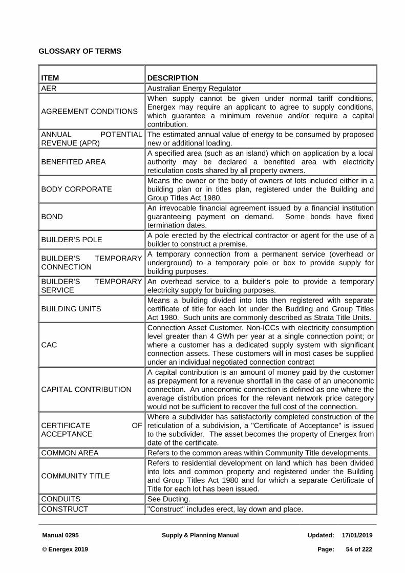
Manual 0295
Supply & Planning Manual
Updated:
17/01/2019 © Energex 2019
Page:
54 of 222
GLOSSARY OF TERMS
ITEM DESCRIPTION
AER Australian Energy Regulator
AGREEMENT CONDITIONS
When supply cannot be given under normal tariff conditions, Energex may require an applicant to agree to supply conditions, which guarantee a minimum revenue and/or require a capital contribution.
ANNUAL POTENTIAL REVENUE (APR)
The estimated annual value of energy to be consumed by proposed new or additional loading.
BENEFITED AREA A specified area (such as an island) which on application by a local authority may be declared a benefited area with electricity reticulation costs shared by all property owners.
BODY CORPORATE Means the owner or the body of owners of lots included either in a building plan or in titles plan, registered under the Building and Group Titles Act 1980.
BOND An irrevocable financial agreement issued by a financial institution guaranteeing payment on demand. Some bonds have fixed termination dates.
BUILDER'S POLE A pole erected by the electrical contractor or agent for the use of a builder to construct a premise.
BUILDER'S TEMPORARY CONNECTION
A temporary connection from a permanent service (overhead or underground) to a temporary pole or box to provide supply for building purposes.
BUILDER'S TEMPORARY SERVICE
An overhead service to a builder's pole to provide a temporary electricity supply for building purposes.
BUILDING UNITS Means a building divided into lots then registered with separate certificate of title for each lot under the Budding and Group Titles Act 1980. Such units are commonly described as Strata Title Units.
CAC
Connection Asset Customer. Non-ICCs with electricity consumption level greater than 4 GWh per year at a single connection point; or where a customer has a dedicated supply system with significant connection assets. These customers will in most cases be supplied under an individual negotiated connection contract
CAPITAL CONTRIBUTION
A capital contribution is an amount of money paid by the customer as prepayment for a revenue shortfall in the case of an uneconomic connection. An uneconomic connection is defined as one where the average distribution prices for the relevant network price category would not be sufficient to recover the full cost of the connection.
CERTIFICATE OF ACCEPTANCE
Where a subdivider has satisfactorily completed construction of the reticulation of a subdivision, a "Certificate of Acceptance" is issued to the subdivider. The asset becomes the property of Energex from date of the certificate.
COMMON AREA Refers to the common areas within Community Title developments.
COMMUNITY TITLE
Refers to residential development on land which has been divided into lots and common property and registered under the Building and Group Titles Act 1980 and for which a separate Certificate of Title for each lot has been issued.
CONDUITS See Ducting.
CONSTRUCT "Construct" includes erect, lay down and place.
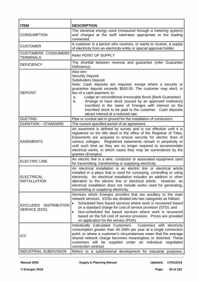
Manual 0295
Supply & Planning Manual
Updated:
17/01/2019 © Energex 2019
Page:
55 of 222
ITEM DESCRIPTION
CONSUMPTION The electrical energy used (measured through a metering system) and charged at the tariff rate/rates appropriate to the loading connected.
CUSTOMER A customer is a person who receives, or wants to receive, a supply of electricity from an electricity entity or special approval holder.
CUSTOMERS CONSUMERS TERMINALS
Refer POINT OF SUPPLY
DEFICIENCY The shortfall between revenue and guarantee (refer Guarantee Deficiency).
DEPOSIT
Also see: Security Deposit Subdividers Deposit Note: Cash deposits are required, except where a security or guarantee deposit exceeds $500.00. The customer may elect, in lieu of a cash payment, to: a. Lodge an unconditional irrevocable Bond (Bank Guarantee) b. Arrange to have stock (issued by an approved institution)
inscribed in the name of Energex with interest on the inscribed stock to be paid to the customer. Cash deposits attract interest at a reduced rate.
DUCTING Pipe or conduit laid in ground for the installation of conductors.
DURATION – STANDARD The current specified period of an agreement.
EASEMENTS
An easement is defined by survey and is not effective until it is registered on the title deed in the office of the Registrar of Titles. Easements are acquired to ensure security for electric lines of various voltages. Registered easements remain in perpetuity or until such time as they are no longer required to accommodate electrical works, in which cases they may be surrendered by the grantee (Energex).
ELECTRIC LINE An electric line is a wire, conductor or associated equipment used for transmitting, transforming or supplying electricity.
ELECTRICAL INSTALLATION
An electrical installation is an electric line or electrical article installed in a place that is used for conveying, controlling or using electricity. An electrical installation includes an addition or other alteration to the electric line or electrical article. However, an electrical installation does not include works used for generating, transmitting or supplying electricity.
EXCLUDED DISTRIBUTION SERVICE (EDS)
Services which Energex provides that are ancillary to the main network services. EDSs are divided into two categories as follows:
Scheduled fees based services where work is recovered based on a standard charge for cost of service provision (STD); and
Non-scheduled fee based services where work is recovered based on the full cost of service provision. Prices are provided on application for the service (POA).
ICC
Individually Calculated Customers. Customers with electricity consumption greater than 40 GWh per year at a single connection point; or where a customer’s circumstances mean that the average shared network charge becomes meaningless or distorted. These customers will be supplied under an individual negotiated connection contract.
INDUSTRIAL SUBDIVISION Refers to a subdivisional development for industrial purposes.
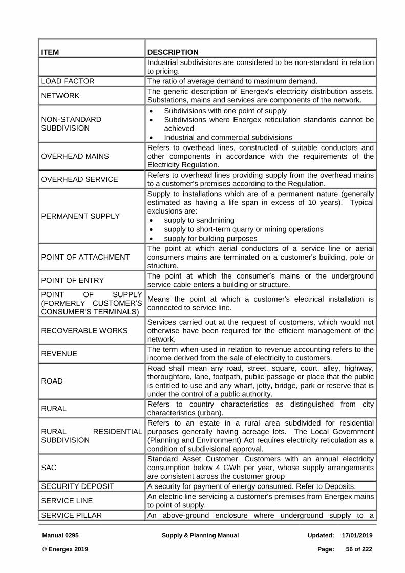
Manual 0295
Supply & Planning Manual
Updated:
17/01/2019 © Energex 2019
Page:
56 of 222
ITEM DESCRIPTION
Industrial subdivisions are considered to be non-standard in relation to pricing.
LOAD FACTOR The ratio of average demand to maximum demand.
NETWORK The generic description of Energex's electricity distribution assets. Substations, mains and services are components of the network.
NON-STANDARD SUBDIVISION
Subdivisions with one point of supply
Subdivisions where Energex reticulation standards cannot be achieved
Industrial and commercial subdivisions
OVERHEAD MAINS Refers to overhead lines, constructed of suitable conductors and other components in accordance with the requirements of the Electricity Regulation.
OVERHEAD SERVICE Refers to overhead lines providing supply from the overhead mains to a customer's premises according to the Regulation.
PERMANENT SUPPLY
Supply to installations which are of a permanent nature (generally estimated as having a life span in excess of 10 years). Typical exclusions are:
supply to sandmining
supply to short-term quarry or mining operations
supply for building purposes
POINT OF ATTACHMENT The point at which aerial conductors of a service line or aerial consumers mains are terminated on a customer's building, pole or structure.
POINT OF ENTRY The point at which the consumer’s mains or the underground service cable enters a building or structure.
POINT OF SUPPLY (FORMERLY CUSTOMER’S CONSUMER’S TERMINALS)
Means the point at which a customer's electrical installation is connected to service line.
RECOVERABLE WORKS Services carried out at the request of customers, which would not otherwise have been required for the efficient management of the network.
REVENUE The term when used in relation to revenue accounting refers to the income derived from the sale of electricity to customers.
ROAD
Road shall mean any road, street, square, court, alley, highway, thoroughfare, lane, footpath, public passage or place that the public is entitled to use and any wharf, jetty, bridge, park or reserve that is under the control of a public authority.
RURAL Refers to country characteristics as distinguished from city characteristics (urban).
RURAL RESIDENTIAL SUBDIVISION
Refers to an estate in a rural area subdivided for residential purposes generally having acreage lots. The Local Government (Planning and Environment) Act requires electricity reticulation as a condition of subdivisional approval.
SAC Standard Asset Customer. Customers with an annual electricity consumption below 4 GWh per year, whose supply arrangements are consistent across the customer group
SECURITY DEPOSIT A security for payment of energy consumed. Refer to Deposits.
SERVICE LINE An electric line servicing a customer's premises from Energex mains to point of supply.
SERVICE PILLAR An above-ground enclosure where underground supply to a
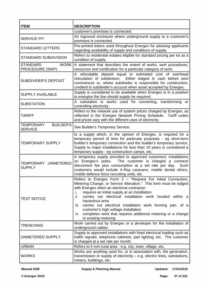
Manual 0295
Supply & Planning Manual
Updated:
17/01/2019 © Energex 2019
Page:
57 of 222
ITEM DESCRIPTION
customer's premises is connected.
SERVICE PIT An inground enclosure where underground supply to a customer's premises is connected.
STANDARD LETTERS Pre-printed letters used throughout Energex for advising applicants regarding availability of supply and conditions of supply.
STANDARD SUBDIVISION Refers to residential estates eligible for standard pricing per lot as a condition of supply.
STANDARD WORK PROCEDURE (SWP)
A statement that describes the extent of works, wort procedures, resources and certification for a particular category of work.
SUBDIVIDER'S DEPOSIT
A refundable deposit equal to estimated cost of overhead reticulation of subdivision. Either lodged in cash before wort commences or, where subdivider is responsible for construction, credited to subdivider's account when asset accepted by Energex.
SUPPLY AVAILABLE Supply is considered to be available when Energex is in a position to energise the line should supply be required.
SUBSTATION A substation is works used for converting, transforming or controlling electricity.
TARIFF Refers to the network use of system prices charged by Energex, as reflected in the Energex Network Pricing Schedule. Tariff codes and prices vary with the different uses of electricity.
TEMPORARY BUILDER'S SERVICE
See Builder's Temporary Service.
TEMPORARY SUPPLY
Is a supply which, in the opinion of Energex. is required for a temporary period of time for particular purposes - eg short-term builder's temporary connection and the builder's temporary service. Supply to major installations for less than 10 years is considered a temporary supply - eg construction camps, etc.
TEMPORARY UNMETERED SUPPLY
A temporary supply provided to approved customers' installations on Energex's poles. The customer is charged a connect/ disconnect fee plus consumption at a set rate per day. Such customers would include X-Ray caravans, mobile dental clinics, mobile defence force recruiting units, etc.
TEST NOTICE
Refers to Energex Form 2 – "Request For Initial Connection, Metering Change, or Service Alteration." This form must be lodged with Energex when an electrical contractor: i. requires an initial supply at an installation ii. carries out electrical installation work located within a
hazardous area iii. carries out electrical installation work forming pan. of a
customer's high voltage installation iv. completes work that requires additional metering or a change
to existing metering
TRENCHING Work carried out by Energex or a developer for the installation of underground cables.
UNMETERED SUPPLY Supply to approved installations with fixed electrical loading such as traffic signals, telephone cabinets, part lighting, etc. The customer is charged at a set rate per month.
URBAN Refers to it non-rural area - e.g. city, town, village, etc.
WORKS Works are anything used for, or in association with, the generation, transmission or supply of electricity – e.g. electric lines, substations, meters, buildings, etc.
Manual 0295
Supply & Planning Manual
Updated:
17/01/2019 © Energex 2019
Page:
58 of 222
ITEM DESCRIPTION
WORKS AUTHORISATION Financial approval of capital expenditure for purchases and for construction work including extensions and additions of mains to provide a supply of electricity.
WORKS ORDER A Works Order is issued to Hubs as an instruction to carry out capital works, which have been authorised on a Works Authorisation or by Hubs to carry out nominated maintenance works.
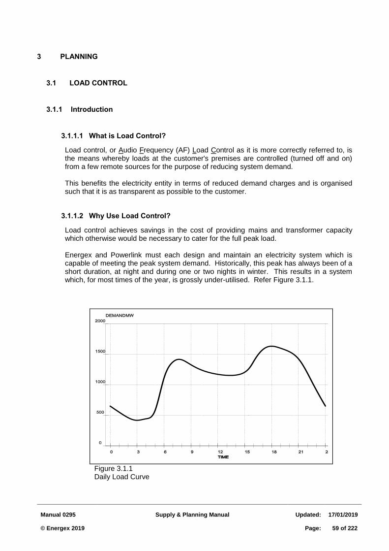
Manual 0295
Supply & Planning Manual
Updated:
17/01/2019 © Energex 2019
Page:
59 of 222
3 PLANNING
3.1 LOAD CONTROL
3.1.1 Introduction
What is Load Control? 3.1.1.1
Load control, or Audio Frequency (AF) Load Control as it is more correctly referred to, is the means whereby loads at the customer's premises are controlled (turned off and on) from a few remote sources for the purpose of reducing system demand.
This benefits the electricity entity in terms of reduced demand charges and is organised such that it is as transparent as possible to the customer.
Why Use Load Control? 3.1.1.2
Load control achieves savings in the cost of providing mains and transformer capacity which otherwise would be necessary to cater for the full peak load.
Energex and Powerlink must each design and maintain an electricity system which is capable of meeting the peak system demand. Historically, this peak has always been of a short duration, at night and during one or two nights in winter. This results in a system which, for most times of the year, is grossly under-utilised. Refer Figure 3.1.1.
Figure 3.1.1 Daily Load Curve
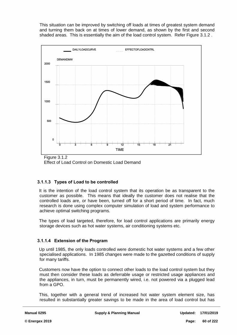
Manual 0295
Supply & Planning Manual
Updated:
17/01/2019 © Energex 2019
Page:
60 of 222
This situation can be improved by switching off loads at times of greatest system demand and turning them back on at times of lower demand, as shown by the first and second shaded areas. This is essentially the aim of the load control system. Refer Figure 3.1.2 .
Types of Load to be controlled 3.1.1.3
It is the intention of the load control system that its operation be as transparent to the customer as possible. This means that ideally the customer does not realise that the controlled loads are, or have been, turned off for a short period of time. In fact, much research is done using complex computer simulation of load and system performance to achieve optimal switching programs.
The types of load targeted, therefore, for load control applications are primarily energy
storage devices such as hot water systems, air conditioning systems etc.
Extension of the Program 3.1.1.4
Up until 1985, the only loads controlled were domestic hot water systems and a few other specialised applications. In 1985 changes were made to the gazetted conditions of supply for many tariffs.
Customers now have the option to connect other loads to the load control system but they
must then consider these loads as deferrable usage or restricted usage appliances and the appliances, in turn, must be permanently wired, i.e. not powered via a plugged lead from a GPO.
This, together with a general trend of increased hot water system element size, has
resulted in substantially greater savings to be made in the area of load control but has
Figure 3.1.2 Effect of Load Control on Domestic Load Demand
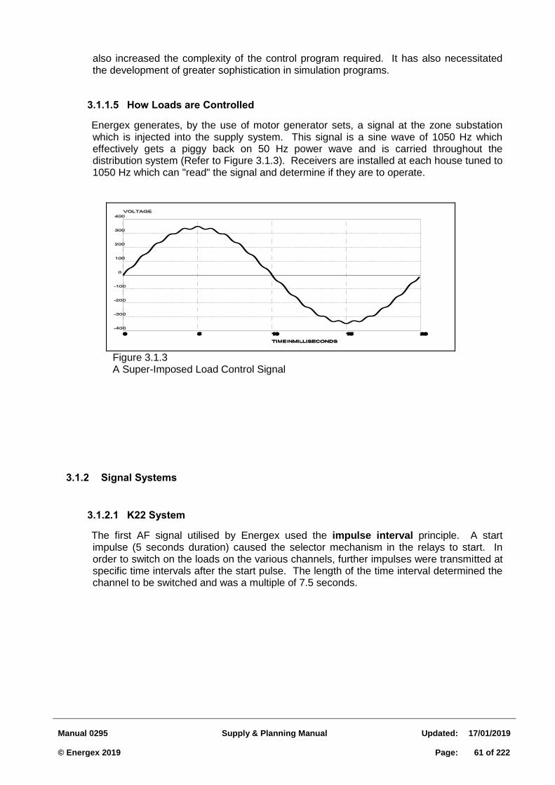
Manual 0295
Supply & Planning Manual
Updated:
17/01/2019 © Energex 2019
Page:
61 of 222
also increased the complexity of the control program required. It has also necessitated the development of greater sophistication in simulation programs.
How Loads are Controlled 3.1.1.5
Energex generates, by the use of motor generator sets, a signal at the zone substation which is injected into the supply system. This signal is a sine wave of 1050 Hz which effectively gets a piggy back on 50 Hz power wave and is carried throughout the distribution system (Refer to Figure 3.1.3). Receivers are installed at each house tuned to 1050 Hz which can "read" the signal and determine if they are to operate.
3.1.2 Signal Systems
K22 System 3.1.2.1
The first AF signal utilised by Energex used the impulse interval principle. A start impulse (5 seconds duration) caused the selector mechanism in the relays to start. In order to switch on the loads on the various channels, further impulses were transmitted at specific time intervals after the start pulse. The length of the time interval determined the channel to be switched and was a multiple of 7.5 seconds.
Figure 3.1.3 A Super-Imposed Load Control Signal
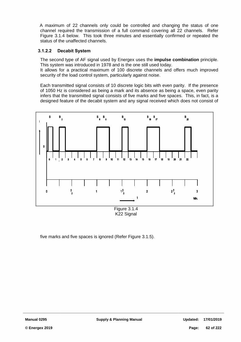
Manual 0295
Supply & Planning Manual
Updated:
17/01/2019 © Energex 2019
Page:
62 of 222
A maximum of 22 channels only could be controlled and changing the status of one channel required the transmission of a full command covering all 22 channels. Refer Figure 3.1.4 below. This took three minutes and essentially confirmed or repeated the status of the unaffected channels.
Decabit System 3.1.2.2
The second type of AF signal used by Energex uses the impulse combination principle. This system was introduced in 1978 and is the one still used today.
It allows for a practical maximum of 100 discrete channels and offers much improved security of the load control system, particularly against noise.
Each transmitted signal consists of 10 discrete logic bits with even parity. If the presence
of 1050 Hz is considered as being a mark and its absence as being a space, even parity infers that the transmitted signal consists of five marks and five spaces. This, in fact, is a designed feature of the decabit system and any signal received which does not consist of
five marks and five spaces is ignored (Refer Figure 3.1.5).
Figure 3.1.4 K22 Signal
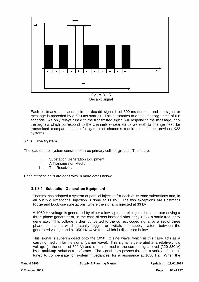
Manual 0295
Supply & Planning Manual
Updated:
17/01/2019 © Energex 2019
Page:
63 of 222
Each bit (marks and spaces) in the decabit signal is of 600 ms duration and the signal or
message is preceded by a 600 ms start bit. This summates to a total message time of 6.6 seconds. As only relays tuned to the transmitted signal will respond to the message, only the signals which correspond to the channels whose status we wish to change need be transmitted (compared to the full gambit of channels required under the previous K22 system).
3.1.3 The System
The load control system consists of three primary cells or groups. These are:
I. Substation Generation Equipment. II. A Transmission Medium.
III. The Receiver. Each of these cells are dealt with in more detail below.
Substation Generation Equipment 3.1.3.1
Energex has adopted a system of parallel injection for each of its zone substations and, in all but two exceptions, injection is done at 11 kV. The two exceptions are Postmans Ridge and Lockrose substations, where the signal is injected at 33 kV.
A 1050 Hz voltage is generated by either a low slip squirrel cage induction motor driving a
three phase generator or, in the case of sets installed after early 1988, a static frequency generator. This voltage is then converted to the correct coded signal by a set of three phase contactors which actually toggle, or switch, the supply system between the generated voltage and a 1050 Hz wave trap, which is discussed below.
This signal is superimposed onto the 1050 Hz sine wave, which in this case acts as a
carrying medium for the signal (carrier wave). This signal is generated at a relatively low voltage (in the order of 500 V) and is transformed to the correct signal level (220-330 V) by a multi-tap isolation transformer. The signal then passes through a series LC circuit, tuned to compensate for system impedances, for a resonance at 1050 Hz. When the
Figure 3.1.5 Decabit Signal
Manual 0295
Supply & Planning Manual
Updated:
17/01/2019 © Energex 2019
Page:
64 of 222
generator is not generating and transmitting an active signal, the supply system is connected through a tuned wave trap to earth. This wave trap effectively soaks up or sinks any stray 1050 Hz signal and acts to prevent spill-over signal from adjacent substations affecting relays in the area of control.
The substation injection equipment configuration can be seen in Figure 3.1.6.
The Control Unit
The times of transmission and the transmitted code or signal are controlled from either an M4controller or a SACS (Substation Automated Control System) or mini-SACS control unit installed in the substation. These units also monitor relay status and signal integrity, raising alarms if the signal is below pre-determined threshold limits. An alarm will also be raised if a 1050 Hz signal is detected and the generator is not running, thus indicating a spill-over problem.
The M4 controllers are control units supplied by Zellweger. They contain inbuilt clocks
and are programmed to control all signal transmissions from that substation but are capable of talking to other control units. These units have been superseded by Energex-designed and built SACS units.
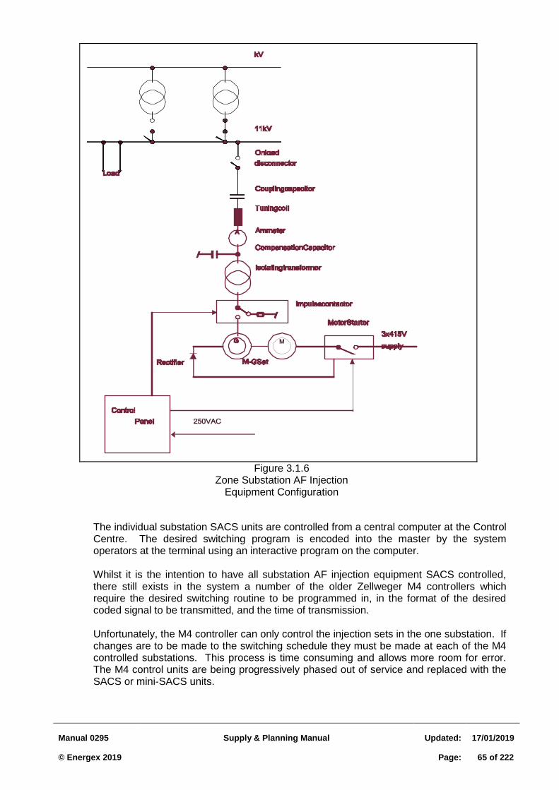
Manual 0295
Supply & Planning Manual
Updated:
17/01/2019 © Energex 2019
Page:
65 of 222
The individual substation SACS units are controlled from a central computer at the Control
Centre. The desired switching program is encoded into the master by the system operators at the terminal using an interactive program on the computer.
Whilst it is the intention to have all substation AF injection equipment SACS controlled,
there still exists in the system a number of the older Zellweger M4 controllers which require the desired switching routine to be programmed in, in the format of the desired coded signal to be transmitted, and the time of transmission.
Unfortunately, the M4 controller can only control the injection sets in the one substation. If
changes are to be made to the switching schedule they must be made at each of the M4 controlled substations. This process is time consuming and allows more room for error. The M4 control units are being progressively phased out of service and replaced with the SACS or mini-SACS units.
Figure 3.1.6 Zone Substation AF Injection
Equipment Configuration
Manual 0295
Supply & Planning Manual
Updated:
17/01/2019 © Energex 2019
Page:
66 of 222
Equipment Rating
One of the key factors which limits any switching program is the thermal limitation of the injection equipment. Substation injection equipment intended for K22 signal injection, or mixed K22/Decabit injection, has a different rating (higher) than equipment intended for decabit injection only.
K22 Equipment - Generator 16% duty (total run time) Cell 16% duty (actual injection time) 16% duty (total run time) = 3 runs/hr 16% duty (actual injection time) = 3 runs/hr
It can be seen from the above that the rating of the generator is the limiting factor which must be catered for during design.
Decabit equipment – Generator 16% duty (total run time) = 87 signals/hr Cell:
Isol Trans 16% duty
Tuning Coil 5% duty (actual injection time)
Coupling Cap 5% duty 16% duty (actual injection time) = 160 signals/hr 5% duty (actual injection time) = 50 signals/hr
One of the key factors which limits any switching program is the thermal limitation of the injection equipment. Substation injection equipment intended for K22 signal injection, or mixed K22/Decabit injection, has a different rating (higher) than equipment intended for decabit injection only.
The above indicates that the limiting components in the decabit system are the tuning
coils and coupling capacitors. Of these, the coupling capacitor is more critical, i.e. can least withstand an overload.
Static Frequency Injection Sets - All static frequency injection sets purchased by Energex from Zellweger are designed for
a 100% duty cycle, although the coupling cells are still restricted to the duty cycles shown above.
Basis for Ratings -
Coupling equipment is designed for a hot spot temperature of 80C. This is based on the aggregate of various contributing factors, as follows:
Ambient 40C
50 Hz residual current 10C
1050 Hz signal 30C
80C
Manual 0295
Supply & Planning Manual
Updated:
17/01/2019 © Energex 2019
Page:
67 of 222
It follows from the above that, in special circumstances, the maximum duty cycles stated earlier may be exceeded. Each case must be considered as unique and referred to the Field Tests and Projects Manager for a determination.
NOTE: The term "actual injection time" or "active injection time" as used above refers to the
actual portion of the signal when a mark or 1050 Hz current is actually injected into the system. The "space" segments of a transmitted signal are not counted for the determination of the actual injection time. As the 6.6 seconds signal time for a decabit signal consists of a 0.6 second start bit followed by a combination of five marks and five spaces, it has an actual injected current time of 3.6 seconds.
Tuning of Substation AF Injection Equipment Each AF injection set must be uniquely tuned to the existing substation configuration before
control signals can be generated. This is a key step in the commissioning of the injection set. Incorrect tunings can result in the generator becoming overloaded and burning out, insufficient signal level being generated to activate the relays or too large a signal being generated and causing "noise" problems as discussed later. The cells must also be tuned to correctly soak up or sink all unwanted spill-over signal from adjacent generation points.
Parameters which must be determined for the accurate turning of an injection cell are: Number of zone transformers the cell is to feed. Name plate rating of each of the transformers. Per unit impedance of each of the transformers. Six month emergency rating for the zone substation. Manufacturers test data for each component of the injection cell. Size of compensating capacitors to be used. Q factor of the zone transformers (assume 9). Q factor of the isolation transformer (assume 160). A PC program has been developed which performs the complex calculations involved in
tuning a Zellweger injection cell. It is important to note from Figure 3.1.6 that the 11 kV network is always connected through
the cell to either the generator or, more commonly, earth. The frequency response of series and parallel LC circuits can be seen in Figure 3.1.7. The coupling cell, being a series LC circuit, is tuned such that resonance occurs at 1050 Hz but that the sufficiently high impedance at 50 Hz is seen by the network thus limiting the leakage current to earth.
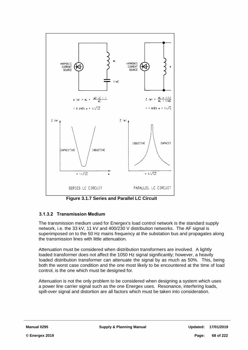
Manual 0295
Supply & Planning Manual
Updated:
17/01/2019 © Energex 2019
Page:
68 of 222
Transmission Medium 3.1.3.2
The transmission medium used for Energex's load control network is the standard supply network, i.e. the 33 kV, 11 kV and 400/230 V distribution networks. The AF signal is superimposed on to the 50 Hz mains frequency at the substation bus and propagates along the transmission lines with little attenuation.
Attenuation must be considered when distribution transformers are involved. A lightly loaded transformer does not affect the 1050 Hz signal significantly; however, a heavily
loaded distribution transformer can attenuate the signal by as much as 50%. This, being both the worst case condition and the one most likely to be encountered at the time of load control, is the one which must be designed for.
Attenuation is not the only problem to be considered when designing a system which uses a power line carrier signal such as the one Energex uses. Resonance, interfering loads, spill-over signal and distortion are all factors which must be taken into consideration.
Figure 3.1.7 Series and Parallel LC Circuit
Manual 0295
Supply & Planning Manual
Updated:
17/01/2019 © Energex 2019
Page:
69 of 222
Introduction of Load Control into an Area Loads and distribution systems (low voltage) often behave much differently at 1050 Hz than
they do at 50 Hz. 1050 Hz is the frequency chosen by Energex to operate its load control relays. Problems have been encountered in the past when load control has been introduced into a distribution area.
The purpose of this section is to establish a sequence of events which will reduce AFLC
problems. The Cause of Interference - Distribution systems are designed to have an equal loading across phases at 50 Hz.
Unfortunately, due to the effects of inductance and capacitance, the system can appear quite different at 1050 Hz.
Some loads, particularly capacitive loads, act as a sink and soak up the 1050 Hz signal.
Other loads can act as a 1050 Hz intensifier and amplify the signal to a nuisance level. Inductive Reactance = 2 π f L π = 3.14159 f = frequency Capacitive Reactance = 1/(2 π f C) L = Inductance C = Capacitance Prior to Commissioning - Before injection equipment is installed in a zone substation, the area it supplies should be
examined for potential causes of problems. Large banks of discharge lighting are by far the main cause of problems due to the presence of their capacitors and will affect loads supplied on the same low voltage network. Distribution transformers act as a block for the interference.
Schools with night classes, after hours service stations, shopping centres etc. should be
identified and, where practical, isolated to unique LV areas. This will sometimes be possible with larger shopping centres.
Where it is not practical to isolate these loads to their own transformer, the area should be
noted for further study after the injection equipment is commissioned. At time of commissioning - When the injection equipment in the substation is to be commissioned, it will be necessary
to have field crews monitoring the 1050 Hz signal voltage on the 400V network to confirm correct signal propagation.
Substation Test personnel establish correct signal strength on the 11 kV bus by measuring
the signal on the 110V VT. As this transformer is generally only lightly loaded with a high power factor load, little attenuation of the AF signal occurs. A heavily loaded distribution transformer can attenuate the AF signal by as much as 50%. It is therefore important to monitor the signal level at various locations on the network. Voltage recorders sensitive to 1050 Hz are available in all districts and should be used for the measurement of signal level. Also available are special 1050 Hz hand held voltmeters.
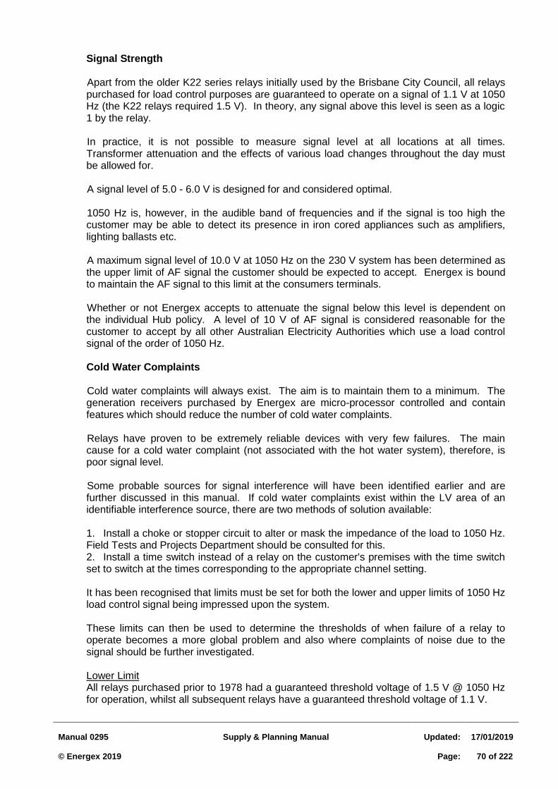
Manual 0295
Supply & Planning Manual
Updated:
17/01/2019 © Energex 2019
Page:
70 of 222
Signal Strength Apart from the older K22 series relays initially used by the Brisbane City Council, all relays
purchased for load control purposes are guaranteed to operate on a signal of 1.1 V at 1050 Hz (the K22 relays required 1.5 V). In theory, any signal above this level is seen as a logic 1 by the relay.
In practice, it is not possible to measure signal level at all locations at all times.
Transformer attenuation and the effects of various load changes throughout the day must be allowed for.
A signal level of 5.0 - 6.0 V is designed for and considered optimal. 1050 Hz is, however, in the audible band of frequencies and if the signal is too high the
customer may be able to detect its presence in iron cored appliances such as amplifiers, lighting ballasts etc.
A maximum signal level of 10.0 V at 1050 Hz on the 230 V system has been determined as
the upper limit of AF signal the customer should be expected to accept. Energex is bound to maintain the AF signal to this limit at the consumers terminals.
Whether or not Energex accepts to attenuate the signal below this level is dependent on
the individual Hub policy. A level of 10 V of AF signal is considered reasonable for the customer to accept by all other Australian Electricity Authorities which use a load control signal of the order of 1050 Hz.
Cold Water Complaints Cold water complaints will always exist. The aim is to maintain them to a minimum. The
generation receivers purchased by Energex are micro-processor controlled and contain features which should reduce the number of cold water complaints.
Relays have proven to be extremely reliable devices with very few failures. The main
cause for a cold water complaint (not associated with the hot water system), therefore, is poor signal level.
Some probable sources for signal interference will have been identified earlier and are
further discussed in this manual. If cold water complaints exist within the LV area of an identifiable interference source, there are two methods of solution available:
1. Install a choke or stopper circuit to alter or mask the impedance of the load to 1050 Hz. Field Tests and Projects Department should be consulted for this. 2. Install a time switch instead of a relay on the customer's premises with the time switch set to switch at the times corresponding to the appropriate channel setting.
It has been recognised that limits must be set for both the lower and upper limits of 1050 Hz
load control signal being impressed upon the system. These limits can then be used to determine the thresholds of when failure of a relay to
operate becomes a more global problem and also where complaints of noise due to the signal should be further investigated.
Lower Limit All relays purchased prior to 1978 had a guaranteed threshold voltage of 1.5 V @ 1050 Hz
for operation, whilst all subsequent relays have a guaranteed threshold voltage of 1.1 V.
Manual 0295
Supply & Planning Manual
Updated:
17/01/2019 © Energex 2019
Page:
71 of 222
To allow for areas of moderate 1050 Hz attenuation, a signal strength of TWICE threshold is designed for, for example, 2.2 - 2.0 V @ 1050 Hz.
Upper Limit 1050 Hz is in the audio band frequencies and can often be heard in iron-cored devices. A
balance is necessary, therefore, between the requirements of sufficient signal to ensure correct propagation and the minimum level determined as a nuisance.
10 V @ 1050 Hz has been determined as the upper limit which is acceptable to both
Energex and their customers. Their upper level of acceptance is also in line with the upper limits set by many other supply
authorities who use AFLC at 1050 Hz.
Manual 0295
Supply & Planning Manual
Updated:
17/01/2019 © Energex 2019
Page:
72 of 222
3.2 SUPPLY TO LARGE INSTALLATIONS
3.2.1 Introduction
The usual method of supplying domestic installations and smaller industrial and commercial premises is to connect them directly to the low voltage network, i.e. at 400/230 V, in the "road reserve" via underground or overhead service mains.
An alternative method of supplying the load is necessary where the expected load of a single service to an individual customer or group of customers (e.g. housing units, shops, etc.), is likely to:
exceed the present capacity in the service main
overload the existing distribution substation, or
otherwise impair the quality of supply to neighbouring customers. This may take the form of load relief on the existing (11 kV/400 V) distribution substation by:
rearranging the low voltage open points
re-conductoring of the low voltage mains, or
establishing a new distribution substation in the "road reserve" adjacent to the load.
Where the aggregate load of an individual customer or group of customers exceeds 100 kVA (139 amps per phase), the Electricity Regulation 2006 permits Energex to request that a distribution substation be established on the customers' premises. This right is exercised provided that the method of supply chosen is the most practical and involves the least community cost.
The method of supplying installations that require their own distribution substations is known simply as "Supply to Large Installations". It should also be noted that the minimum size padmount transformer is 315 kVA.
Since each installation will be significantly different to make it unique in its own right, the objective of this section is to provide guidelines for those whose task it is to design a method of supply to these large installations.
Based on the size of customer with regard to demand and estimated energy consumption (refer to section 2.7) a determination needs to made on the form of supply offer. For ICC’s and CAC’s a negotiated connection agreement will generally be required with site specific network pricing calculations applying (refer to RED 0768 Large Customer Connection Manual for details.) For SAC’s the supply offer process as outlined in this section will apply.
Some large Commercial and Industrial Customers including Embedded Generators may elect to make a connection enquiry or application under the National Electricity Rules. These enquiries should follow RED 00768 Large Customer Connection process.
The following flowchart summarises the planning/design process.
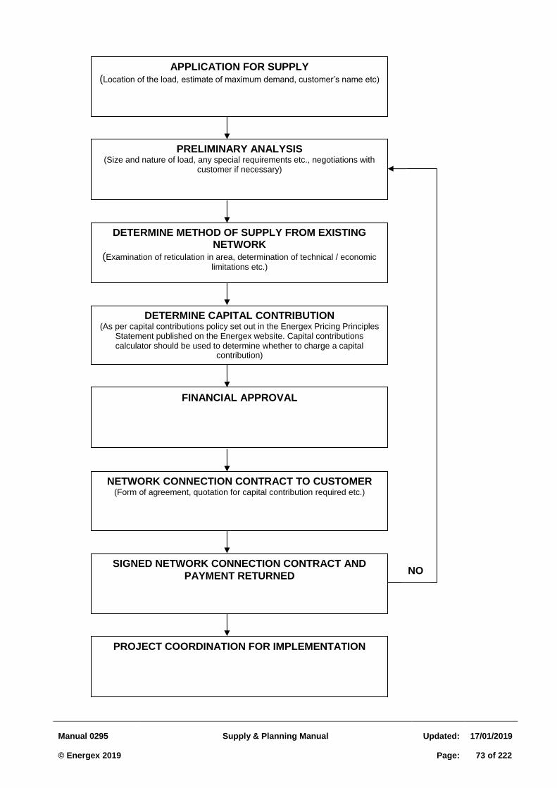
Manual 0295
Supply & Planning Manual
Updated:
17/01/2019 © Energex 2019
Page:
73 of 222
APPLICATION FOR SUPPLY (Location of the load, estimate of maximum demand, customer’s name etc)
PRELIMINARY ANALYSIS (Size and nature of load, any special requirements etc., negotiations with
customer if necessary)
DETERMINE METHOD OF SUPPLY FROM EXISTING NETWORK
(Examination of reticulation in area, determination of technical / economic
limitations etc.)
DETERMINE CAPITAL CONTRIBUTION (As per capital contributions policy set out in the Energex Pricing Principles
Statement published on the Energex website. Capital contributions calculator should be used to determine whether to charge a capital
contribution)
FINANCIAL APPROVAL
NETWORK CONNECTION CONTRACT TO CUSTOMER (Form of agreement, quotation for capital contribution required etc.)
SIGNED NETWORK CONNECTION CONTRACT AND
PAYMENT RETURNED
PROJECT COORDINATION FOR IMPLEMENTATION
NO
Manual 0295
Supply & Planning Manual
Updated:
17/01/2019 © Energex 2019
Page:
74 of 222
3.2.2 Application for Supply
Requests for supply to a large installation (e.g. from customer, Consulting Engineer, Architect or Electrical Contractor), can be made via the Electrical Partners Portal on the Energex website or by phoning 131253. There may be significant lead times (i.e. 9 months) on projects that require network alterations so every attempt should be made to encourage the earliest possible lodgement of a formal application Form 1201.
In some instances it may not be possible to complete applications with any degree of certainty, due to the nature of the project. For example, a building project staged over a number of years, in which the likely type of tenant is unknown and occupancy is also staged. However, in spite of the difficulties a completed application form must be lodged as soon as possible. In addition a Energex planning staff require (as a minimum), data including:
1. location of the proposed building or project; 2. type of industry or purpose of the building; 3. estimated total demand at the completion of the project and the likely loading pattern; 4. size of the largest motor or any special equipment.
Ideally, the level of information required to perform an in-depth assessment of the likely loading is defined in AS/NZS 3000. The level of detail required in AS/NZS 3000 is far greater than that required by the general application process. Every effort should be made to negotiate with the applicant to obtain this information to assist in selecting the most economic method of supply.
Once an application has been formally lodged with Energex (i.e. Network Connection Application F1201 signed and returned), assessment of likely supply options is performed as outlined in the following sections.
3.2.3 Size and Nature Of The Load
Before any supply option can be looked at in detail, it is first of all necessary to critically examine the size and nature of the load. The reason for adopting this approach is that these two aspects affect not only the method of supply chosen but also the possible tariff options as well as the capital contributions by both Energex and the customer (see later sub-sections).
An estimate of demand may be arrived at by several methods, namely:
1. as a total of the connected load of all equipment in the building or project; 2. by using the method of estimating the maximum demand outlined in Australian Standard
AS/NZS 3000 - Wiring Rules; 3. assessed from the proposed usage pattern; or 4. using typical loading figures (VA/m2) from a similar building or project and scaling.
Each of these methods has its advantages and disadvantages. Method 1 provides an estimate of the undiversified demand which if adopted typically results in over design or an over-capitalisation of facilities. It would only be used when there is no diversity or when considering worst possible situations within an installation, e.g. a mine, to determine appropriate cable sizes taking into account voltage drop and thermal ratings. Experience has shown that the method suggested by the Standards Association of Australia also gives an estimate on the high side.
Depending upon the accuracy of the prediction of the proposed loading pattern, the applicability of the typical loading figures chosen and the experience of the person doing the estimate, both of the other methods could also give a high estimate. A full treatment of the various methods of estimating maximum demands for various installations is given in APPENDIX 3.2.A - ESTIMATING MAXIMUM DEMANDS OF LARGE INSTALLATIONS. In the meantime
Manual 0295
Supply & Planning Manual
Updated:
17/01/2019 © Energex 2019
Page:
75 of 222
experience gained from similar loads and installations will tend to give the most reasonable estimate.
Once the maximum demand has been determined it is necessary to consider the nature of the load to determine if it will affect the "Quality of Supply" to neighbouring customers (refer section 4).
Special consideration may be required for certain loads which, if interrupted, may cause unsafe conditions or result in damage to equipment or loss of production beyond normal proportions. Hospitals, some high rise buildings, refineries, chemical plants, water and sewerage treatment plants and similar customers fall into this category. An appreciation of any special supply requirements at an early stage (e.g. such as full alternate supply and its economic implications), may save unnecessary evaluation of unsuitable options.
Ideally, Energex prefers a customer to provide indication of the likely loading pattern at the time of application and highlight any special equipment that may cause "Quality of Supply" problems. This may include a simple statement like "full load consisting of 200 kW of light and power plus a 100 kW arc welder for eight hours dropping to 50 kW overnight". In the case of more informed customers the statement may be "300 kW of load which includes a 100 kW arc welder with an average load factor of 0.3".
Load Factor is the ratio which indicates the average level of usage for any period of time compared with the highest level of usage averaged over 30 minutes, ie the maximum demand during that period. It may be estimated by:
kWh in period
Load Factor = maximum demand (kW) x No. of hours in period
Load factors for various types of customers may be estimated as outlined in APPENDIX 3.2.B - ESTIMATION OF THE LOAD FACTOR.
3.2.4 Methods of Supplying Load From The Network
The method of supplying the load from either the existing 11 kV or 400 V network is largely determined by the type of reticulation in the immediate area of the proposed installation.
Before a method of supply can be determined, a number of factors need to be studied to ascertain if there are any network constraints or technical limitations associated with installing and maintaining any particular method, namely:
(i) Is 11 kV or 400 V supply already available in the vicinity of the proposed installation or
will the network have to be extended? (ii) Will the additional loading cause an overload on the existing system equipment, lines,
etc? (iii) Will the additional loading cause voltage levels at the new installation and elsewhere to
fall below the minimum statutory limit? (iv) Will the nature of the new load adversely affect the quality of supply to neighbouring
customers?
Manual 0295
Supply & Planning Manual
Updated:
17/01/2019 © Energex 2019
Page:
76 of 222
(v) Will the method of supply lead to the possibility of ferroresonance in distribution transformers?
(vi) Will the method of supply need special protection considerations?
(vii) Will the method of supply chosen offer an adequate level of reliability?
(viii) Will the LV conductor length exceed the protective length of the distribution transformer fuse
If 11 kV or 400 V supply is not available in the immediate vicinity of the proposed installation, it will be necessary to extend the network. When making this choice, it should be borne in mind that other potential customers may choose to develop in the same area and the extension should be sized accordingly.
Where supply is to be taken from either the existing 11 kV or 400 V network, present and future loading levels should be looked at carefully to determine the likelihood of Energex equipment, lines or cables becoming overloaded in the near future. Recommended permissible loading levels of Energex equipment, lines or cables can be found in the relevant sections of the Plant Rating Manual.
In considering some methods of supply it may be necessary to perform 11 kV planning studies or evaluation of abnormal loads to determine the likelihood of voltage violations or waveform distortion. Guidelines on the permissible levels of voltage variation and harmonic distortion for Energex customers are available in Section 4.
Ferroresonant over-voltages can occur in circuits that are characterised by capacitance in series with a non-linear inductance which occurs when the following conditions coincide:
1. 11 kV supply to a transformer is interrupted on one or two phases. This includes 11 kV switching (both opening and closing of single phase links) or the rupturing of one or two 11 kV fuses, eg during a storm.
2. There is very little or no load on the transformer, ie less than 3%.
3. There is an excessive length of underground cable ie capacitance, between the open
switching point and the transformer.
To avoid damage to Energex equipment, maximum lengths of cable that can supply distribution transformers have been determined (refer Section 3.8).
Depending upon its position in the network, the distribution substation or method of supply under consideration may need special protection requirements (contact Energex Protection Department).
Energex does not perform quantitative reliability studies as a matter of routine for every planning or design project. Some idea of the level of reliability, i.e.-average number of outages per year and average outage time, of the method of supply being considered can be obtained by collating the data from the yearly "Reliability Reports" or the "Network Outage System".
For network circuit configurations refer to Standard Network Building Blocks. For methods of supplying and metering customers at 11 kV refer to the Supply section of this manual and the Electricity Connection and Metering Manual.
Manual 0295
Supply & Planning Manual
Updated:
17/01/2019 © Energex 2019
Page:
77 of 222
3.2.5 Establishing Distribution Substations On Customers' Premises
Having chosen the most suitable method of supplying the large installation from the existing network, the next step is to determine which type of substation is the most suitable for that particular installation.
When making a selection from the range of substation options that are available several aspects need to be examined, namely:
(i) the type of substation and its suitability for the environment in which it is to operate;
(ii) the choice of locations within the premises; (iii) the conditions under which supply will be given and the costs incurred by both Energex
and the customer; and (iv) adequate space for all equipment required to be installed within the substation. (v) above the DFL or 1 in 100 year flood level
(vi) for substations to be installed in the Brisbane CBD area, the borders of which align with
Brisbane City Council’s City Plan 2014 Mapping are shown in the map in Appendix 5.1.A, an indoor substation room will be required.
(vii) the requirements for a customer substation with relay controlled switchgear is as follows:
For new developments in the Brisbane CBD area, which are Large Customer Connections, the minimum requirement for the substation room will be to accommodate the provision of relay operated switchgear.
For new developments which are not Large Customer Connections, or outside of the Brisbane CBD, Energex will determine switchgear requirements based on forecast growth, load category, load density and network development plans for the area.
Each of these broad aspects involves the detailed evaluation of several factors which are covered to some degree in the Standard Network Building Blocks, C&I Manual and the section Supply. Since these factors are only covered from an implementation point of view in the abovementioned references, the philosophical reasons for considering them will be discussed in the following sections. A brief review of the types of substations that are available is presented in the following section.
For details on Energex substation requirements and standard room layouts please refer to the existing Energex Commercial and Industrial Substations Manual.
3.2.6 Types of Substation
Several types of substation designs have been adopted for use on customers' premises, viz:
(i) Surface Outdoor Substation
The basic design comprises a transformer sitting on a concrete slab surrounded by a suitable enclosure. Variations to the basic design are available to accommodate additional transformers, ring main units and an outdoor weather-proof or weather protected low voltage switchboard.
Manual 0295
Supply & Planning Manual
Updated:
17/01/2019 © Energex 2019
Page:
78 of 222
(ii) Padmount Substation
This arrangement consists of a transformer and its integral low voltage switching equipment enclosed in a cabinet made of sheet steel, sheet aluminium or fibreglass. The enclosure and internal components is mounted on a concrete base which may be either integral with, or separate from, the cabinet. The design is aesthetically appealing because of its compact nature. It is purchased in capacities (typically 750 and 1000 kVA) with the cabinet constructed of sheet steel.
(iii) Dual Padmount arrangement The dual padmount arrangement is only applicable for Large Customers having a load requirement of 1000kVA to 1600kVA. Current maximum dual padmount size is limited to 2MVA (2x1000kVA). Due to this limitation the dual padmount transformer arrangement shall only be utilised where likelihood of future load increase is very low. Maximum size of HV switchgear in current square type padmount is 3 way. The planning officer needs to consider the potential future load increase in the area before selecting this arrangement. If it is envisaged that an additional switch (4 way) is required in near future then an outdoor/indoor ground transformer site shall be provided. Padmounts are generally arc fault rated for individual fault level. Parallel connection and operation is not permitted. Customer’s low voltage switchboards shall be interconnected by castell key interlock to prevent paralleling. Dual padmount site is not to be located over a basement. This supply arrangement is limited to only two padmounts (outdoor) per site. Padmounts shall be situated side by side facing road reserve or open area. Horizontal separation between padmounts is to facilitate safe construction, operation and maintenance around padmounts. Refer Energex Underground Distribution Construction manual for details regarding electrical and civil construction.
(iv) Surface Building or Chamber Substation This substation consists of a building, or chamber within a building, in which the substation equipment, such as transformers, low voltage switchboard, high voltage switchgear etc., are housed.
(v) Pole Transformer Substation This arrangement consists of a transformer, low voltage disconnect links, drop-out fuses etc mounted on a pole. It is mainly used in rural areas, e.g. quarries, sewerage and water treatment plants etc., and in some industrial situations where overhead mains are tolerated and where the customer decides it is the cheapest to establish.
When making a choice from these options, consideration should also be given to the type of environment in which the substation is to operate. For example, while a pole transformer station may not be acceptable at a cement plant, the build-up of dust, fly ash etc. on insulators may lead to a disproportionately high level of maintenance in future years. In such a case it may be more cost effective to adopt an alternative design initially - one that will not require a high level of maintenance in the future, e.g. a pad mount substation.
Similar situations can occur in marine environments where salt spray can cause corrosion problems, quarries where flying rocks from blasting could cause insulator damage, chemical
Manual 0295
Supply & Planning Manual
Updated:
17/01/2019 © Energex 2019
Page:
79 of 222
plants and oil refineries where hazardous build-up of fumes may require the substation building to be pressurised. Each environment will need to be considered carefully to determine the most suitable type of substation for that location.
Whilst the adoption of an alternative or improved design of substation may solve most problems likely to be experienced from the environment, a wiser choice of location within the property, i.e. move the substation away from the immediate environment that is causing problems, may prove to be a more cost effective solution to the problem. This aspect is considered in the following section.
Choice of Substation Location 3.2.6.1
While it is desirable that the substation site chosen should meet all of the Energex requirements, in practice this rarely happens and in some cases the usual result tends to be a compromise. This situation is most likely to occur where the customer wants to maximise the space available for rental, e.g.` in a commercial building, or where the location of the substation could affect the aesthetic appeal of the building. When selecting a suitable substation site several factors need to be taken into account, viz: (i) Siting in Proximity of the Load Ideally the substation and main low voltage switchboard should be located as close as possible to the electrical centre of the load to minimise the extent of low voltage cabling required as well as the voltage drop at the extremity of the load. Another advantage of locating the station at or near the centre of the load is that the number of additional low voltage switchboards and sub-mains is minimised. (ii) Siting in Sensitive Environmental Areas The site should, if possible, be chosen so that the substation has minimal impact on the immediate environment. The installation of transformers near environmentally sensitive areas should be avoided when a single transformer contains oil volumes above 500L but less than 2000L. These apply to padmount transformers of 750 kVA and 1000 kVA and ground transformers of 750 kVA, 1000 kVA and 1500 kVA.
If the transformer site cannot be located outside the environmentally sensitive area, the options are:
(1) Install smaller sized padmount transformers of 315 kVA or 500 kVA (which
have oil volumes less than 500 litres) (2) Provide oil containment (for example, bunding) to contain any oil spill, internally
or externally to the substation or externally around a padmounted transformer. All external conduits terminating in a substation chamber are to be sealed, after
the cable installation, against the ingress of contaminants
Manual 0295
Supply & Planning Manual
Updated:
17/01/2019 © Energex 2019
Page:
80 of 222
Note: Sensitive Environmental Areas are areas of Protected Estate being - an area dedicated or declared under the Nature Conservation Act 1992 or Marine Parks Act 2004 as national park, conservation park, resources reserve, nature refuge, coordinated conservation area, wilderness area, World Heritage management area, international agreement area or marine park.
Sensitive Environmental Areas may also be those areas immediately adjacent to permanent water bodies, where a direct flow path to the water exists and the transformer would be located in a position that would place it at risk of rupture due to impact.
An example of a transformer located in a Sensitive Environmental Areas would be one where the transformer is located on the top of a creek bank, up slope from the water flow path and in a position where a motor vehicle could collide with it causing tank rupture.
Reference are made in:-
1. RED 00694 – Standard Network Building Blocks - Feeder, clause 4.2.12 2. RED 00293 – C&I Manual, clause 8.2 3. RED 00305 – UDC Manual, clause Sect C3 –Sub – Sect 1 Sh 1
(iii) Access The site has to be accessible to both Energex personnel and equipment 24 hours a day in such a way that there is no need to enter the customers' secure areas. If fencing is installed around the site, gate access to the rear of the substation may be required. Sites must be accessible when there is an electrical outage (i.e. no electric gates to restrict access to Energex equipment). (iv) Internal Reticulation The site should be selected such that the route of the incoming 11 kV feeder (and possibly a low voltage tie to the network), is not prejudiced by excessive directional changes or future development. (v) Future Development Development plans by the customer should be considered for optimal placement of the substation initially as well as any future cable routes. (vi) Flooding The site must be above the Defined Flood Level (DFL) or 1 in 100 year flood level. However, where this is unavoidable due to seepage or localised storm run-off, drainage pits complete with automatic stop/start sump pumps are to be provided within the substation, and a generator connection point at ground level. Alternatively, the drainage pits are to be connected to the stormwater system if the out-fall level permits. All conduits which penetrate building walls shall be sealed against water ingress. (vii) Other Services
Manual 0295
Supply & Planning Manual
Updated:
17/01/2019 © Energex 2019
Page:
81 of 222
No other services such as water pipes, storm water pipes, sewerage pipes etc are permitted within the substation boundary and the site should be chosen so that it is clear of all such services. If this is unavoidable, Energex requires these services to be enclosed in a second outer pipe. The above list represents some factors to be considered when choosing a substation site and is not exhaustive. Only experience with the special requirements of different substations in various locations will determine the most appropriate list of factors to be considered in each individual case.
Conditions of Supply 3.2.6.2
Energex's Policy relating to the special conditions under which supply will be made available to large installations, at either high voltage or low voltage, is given in detail on the Energex Intranet. This section presents a summary of the more important of these conditions.
(i) The Provision of Space for Substations on Customer's Premises:
In accordance with the provisions of the Electricity Regulation 2006, customers are required to provide space on their premises for the purpose of establishing a distribution substation. Furthermore, all of the costs incurred in establishing the site/building to Energex's specification are to be borne by the customer, with the exception of those costs outlined in the Electricity Regulation 2006 to which Energex must make a contribution. Energex will be introducing a larger size distribution substation with automation and telecommunication facilities and the space requirements are being increased to accommodate this. The location of this space and suitable right-of-way for incoming mains is chosen using the criteria listed in Section 3.2.5.2, in consultation with the customer or his agent and is generally made available to Energex free of charge. However, where Energex requires special access to supply other customers from this substation, a mutually agreeable annual rental fee may be payable provided the criteria outlined in the Electricity Regulation 2006 have been satisfied. In general, Energex does not pay rental on the space occupied by the majority of its distribution substations.
(ii) Supply of Transformers and Equipment
Under standard tariffs and subject to capital contributions, Energex will supply, install and maintain a standard substation on the customers' premises, including standard ratio transformers, ie 11 kV/433 V, automotive equipment, and all other necessary equipment to supply the customer’s load.
The per capital contributions policy set out in the Energex Pricing Principles Statement published on the Energex website. Capital contributions are calculated using the capital contributions calculator maintained by Network Pricing. Customers may, by agreement with Energex, provide all the transformers (both standard and non-standard) and/or switchgear and other high voltage equipment. However, in this case the "high voltage" customer must accept responsibility for the operation, maintenance, repair and replacement of all equipment owned by them.
Manual 0295
Supply & Planning Manual
Updated:
17/01/2019 © Energex 2019
Page:
82 of 222
(iii) Multiple Transformers:
Where the maximum demand on the substation does not exceed 1000 kVA, Energex will provide a single transformer substation. However, where the maximum demand exceeds 1000 kVA, Energex will provide the minimum number of transformers of sufficient capacity to meet the maximum demand. Where the customer requests the provision of more than one transformer for purposes other than capacity to meet the maximum demand, e.g. reliability etc., all additional costs incurred are to be met by the customer. These costs are to be calculated according to the methodology outlined in the Energex Network Pricing Principles Statement. This condition does not apply in the case of customers who provide their own equipment.
(iv) Network Low Voltage Supply:
Energex reserves the right to supply other customers from a substation on an individual's premises providing their security of supply is not jeopardised. Where low voltage ties to the network are not required by Energex, and customers request such ties for reliability purposes etc., they are required to meet the full cost of providing this facility.
(v) Excess Cable Charges:
Excess cable charges are applied in accordance with the Electricity Regulation 2006 as follows: a) Underground Low Voltage Service on the Premises:
Where a substation is located in the "road reserve" and a low voltage underground service is provided, the customer is required to pay for the cost of the service in excess of 7 metres measured from the point where it crosses the property boundary. The cost of terminating the service on the customers' premises is met by Energex.
b) Overhead Low Voltage Service on the Premises:
Where a substation is located in the "road reserve" and a low voltage overhead service is provided, the customer is required to pay for the cost of the service in excess of 20 metres measured from the point where it crosses the property boundary. The cost of terminating the service on the customers' premises is met by Energex.
c) Underground 11 kV mains provided on the Premises:
Where the substation is located on the customers' premises, the customer is required to pay for the cost of that part of the 11 kV cable in excess of 7 metres measured along the route from the property boundary to the substation. If more than one circuit is required then excess cable charges shall apply to each circuit (refer to section Supply).
d) Overhead 11 kV mains on the Premises:
Where the 11 kV circuit on the premises consists of overhead mains connected to an underground cable which terminates in the substation, Energex will, free of charge, install the terminal pole, all equipment on the pole associated with the underground cable and the underground cable for a circuit route length not exceeding 7 metres measured from the base of the terminal pole. The
Manual 0295
Supply & Planning Manual
Updated:
17/01/2019 © Energex 2019
Page:
83 of 222
customer shall bear the cost of the remainder of the overhead line including supports within the premises and the underground cable beyond 7 metres.
Where the 11 kV circuit on the premises is connected to a pole transformer
station, Energex will provide, free of cost to the customer, the transformer pole and associated equipment, a short span of low voltage service line to the customers' terminals and a route length of 20 metres of overhead 11 kV line from the property boundary.
The customer shall bear the cost of the remainder of the overhead line and
supports provided by Energex within the premises as well as the low voltage service mains from the termination pole.
e) Low Voltage Network Ties:
Any low voltage circuit to be provided by Energex from the substation for the purposes of supplying customers not located on the premises is not subject to excess cable charges.
(vi) Recoverable Costs and Ownership of Equipment
Before any work is commenced, the customer is required to pay a capital contribution towards the cost of establishing the substation, unless prior arrangements have been made to the contrary. All electric lines and equipment under this arrangement will be owned and maintained by Energex.
For detailed information on capital contributions, please refer to the Energex Network Pricing Principles Statement and the capital contributions calculator maintained by Network Pricing Department.
3.2.7 The Economics of Supply to Large Installations
In the majority of cases, the economic evaluation of supply to large installations only involves the determination of the capital contribution required from the customer since the method of supply from the network and the type of substation to be established will already have been decided on other criteria. Only on rare occasions should it be necessary to decide which is the best option based on an economic comparison of alternative designs for customers metered at 400 volts.
3.2.8 Form of Agreement
The final step in the planning procedure is to formally communicate to the customers the method by which they will be supplied from the existing network and the point of supply, i.e. the customers' terminals. This will take the form of a Network Connection Contract.
The email/letter transmitting these documents to the customer should also advise them of the person the forms are to be returned to, as well as the Hub contact person for project coordination.
The Network Connection Contract will detail all the conditions under which supply is given, viz:
Maximum Connection Capacity
Fees and Charges
Approvals required
Program for Energex Connection Services
Manual 0295
Supply & Planning Manual
Updated:
17/01/2019 © Energex 2019
Page:
84 of 222
Technical and Safety Obligations
General Terms and Conditions
Any special conditions that Energex may have that are appropriate for the connection
Schedule of Work Activities for Energex and the Customer
Manual 0295
Supply & Planning Manual
Updated:
17/01/2019 © Energex 2019
Page:
85 of 222
APPENDIX 3.2.A - ESTIMATING MAXIMUM DEMANDS OF LARGE INSTALLATIONS
1. PURPOSE Estimation of the maximum demand of a large installation is an important part of the
distribution planning and design process. With increasing pressure to curtail the real increase in operating costs, the distribution planner/designer must be decisive in optimising the transformer assets used to supply a large installation.
Should insufficient transformer capacity be installed to supply the initial load or moderate
load growth over, say, the first five years of operation, the undesirable problem of installing additional capacity could result. This could be an extremely expensive exercise costing both the Board and the customer many tens of thousands of dollars. Clearly the customer would be dissatisfied.
Conversely, if an estimate of maximum demand is too high and excessive transformer
capacity is installed, the resultant effect is an over-capitalisation of the installation with increased no load transformer losses. It is essential therefore that the distribution planner/designer consider very carefully the estimation of maximum demand for large installations.
The following information provides a guide for the estimation of maximum demand for large
installations. 2. PROBLEMS LIKELY TO AFFECT THE ESTIMATION PROCESS. Notwithstanding the comments made previously concerning the need for accuracy in
estimating maximum demands, this is not an easy task otherwise a multiplicity of published material would be available and the whole process would be computerised. Such is not the case, however, and it is still one of those areas of engineering where experience, coupled with common sense, is required.
The reason why estimating maximum demands is such a difficult task can be readily
understood when one considers that no two installations will be "exactly identical". By their very nature, the types of load within so called identical buildings will be different; furthermore diversity between loads will affect the maximum demand.
Large installations can be categorised into the following four distinct groups: i) residential ii) commercial iii) industrial iv) rural Table 3.3.A.1 shows various types of installations for each of the abovementioned groups.
Within any particular installation there may be various permutations and combinations of load groups. For example, a hotel complex may include an office block and/or a shopping mall; a rural installation may include a large industrial complex such as a timber mill.
There is a possibility of a multiplicity of types of loads for each group. Table 3.3.A.2 lists the
various types of loads normally associated with the various installation groups.
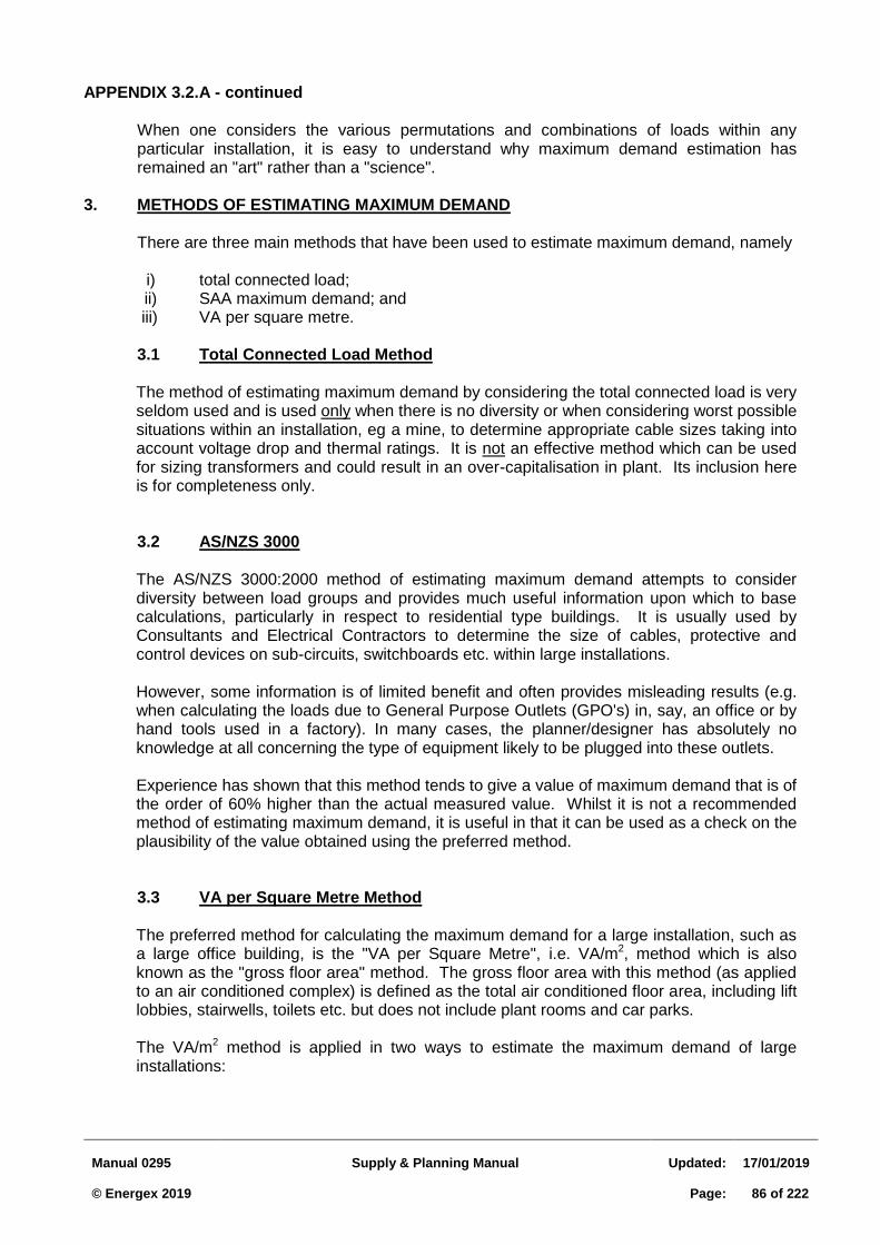
Manual 0295
Supply & Planning Manual
Updated:
17/01/2019 © Energex 2019
Page:
86 of 222
APPENDIX 3.2.A - continued When one considers the various permutations and combinations of loads within any
particular installation, it is easy to understand why maximum demand estimation has remained an "art" rather than a "science".
3. METHODS OF ESTIMATING MAXIMUM DEMAND There are three main methods that have been used to estimate maximum demand, namely i) total connected load; ii) SAA maximum demand; and iii) VA per square metre. 3.1 Total Connected Load Method The method of estimating maximum demand by considering the total connected load is very
seldom used and is used only when there is no diversity or when considering worst possible situations within an installation, eg a mine, to determine appropriate cable sizes taking into account voltage drop and thermal ratings. It is not an effective method which can be used for sizing transformers and could result in an over-capitalisation in plant. Its inclusion here is for completeness only.
3.2 AS/NZS 3000 The AS/NZS 3000:2000 method of estimating maximum demand attempts to consider
diversity between load groups and provides much useful information upon which to base calculations, particularly in respect to residential type buildings. It is usually used by Consultants and Electrical Contractors to determine the size of cables, protective and control devices on sub-circuits, switchboards etc. within large installations.
However, some information is of limited benefit and often provides misleading results (e.g.
when calculating the loads due to General Purpose Outlets (GPO's) in, say, an office or by hand tools used in a factory). In many cases, the planner/designer has absolutely no knowledge at all concerning the type of equipment likely to be plugged into these outlets.
Experience has shown that this method tends to give a value of maximum demand that is of
the order of 60% higher than the actual measured value. Whilst it is not a recommended method of estimating maximum demand, it is useful in that it can be used as a check on the plausibility of the value obtained using the preferred method.
3.3 VA per Square Metre Method The preferred method for calculating the maximum demand for a large installation, such as
a large office building, is the "VA per Square Metre", i.e. VA/m2, method which is also known as the "gross floor area" method. The gross floor area with this method (as applied to an air conditioned complex) is defined as the total air conditioned floor area, including lift lobbies, stairwells, toilets etc. but does not include plant rooms and car parks.
The VA/m2 method is applied in two ways to estimate the maximum demand of large
installations:
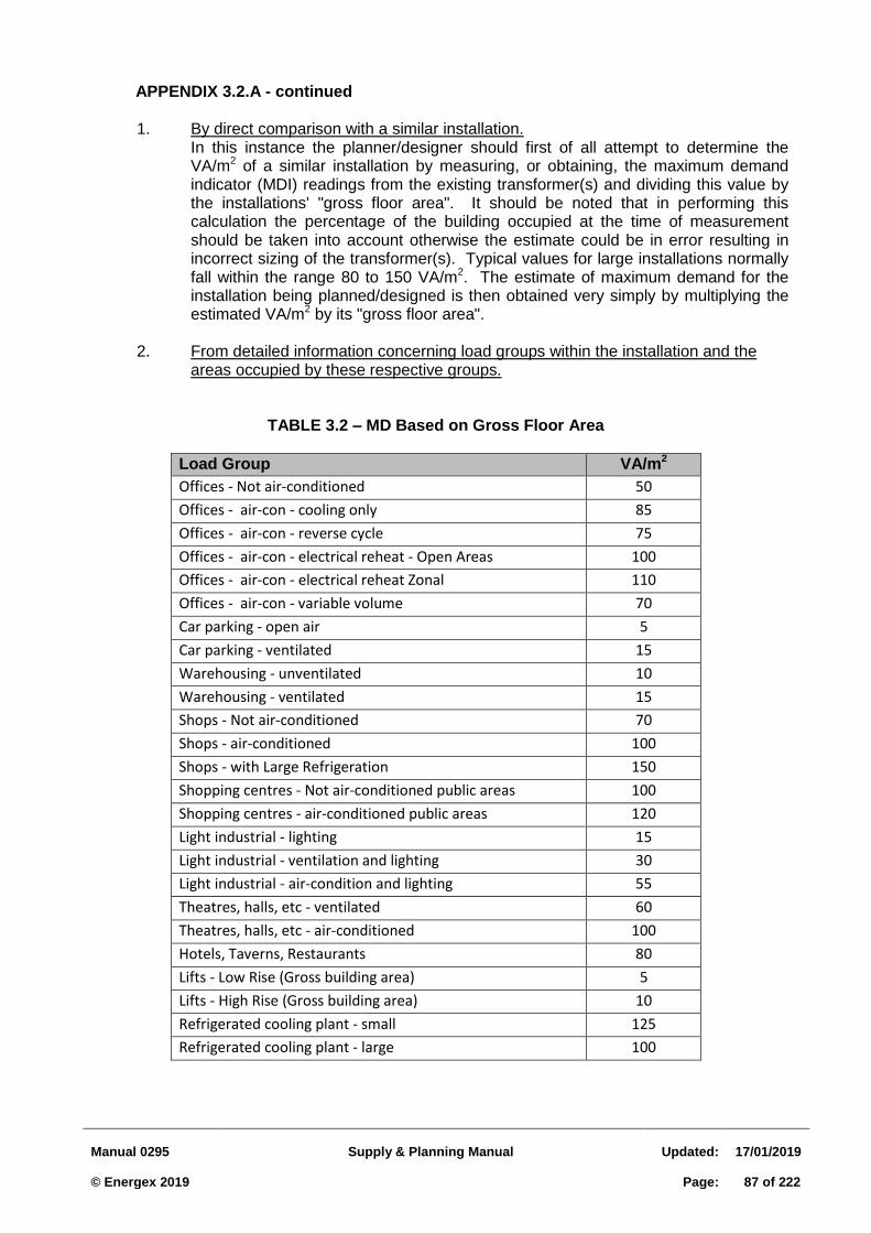
Manual 0295
Supply & Planning Manual
Updated:
17/01/2019 © Energex 2019
Page:
87 of 222
APPENDIX 3.2.A - continued
1. By direct comparison with a similar installation. In this instance the planner/designer should first of all attempt to determine the VA/m2 of a similar installation by measuring, or obtaining, the maximum demand indicator (MDI) readings from the existing transformer(s) and dividing this value by the installations' "gross floor area". It should be noted that in performing this calculation the percentage of the building occupied at the time of measurement should be taken into account otherwise the estimate could be in error resulting in incorrect sizing of the transformer(s). Typical values for large installations normally fall within the range 80 to 150 VA/m2. The estimate of maximum demand for the installation being planned/designed is then obtained very simply by multiplying the estimated VA/m2 by its "gross floor area".
2. From detailed information concerning load groups within the installation and the
areas occupied by these respective groups.
TABLE 3.2 – MD Based on Gross Floor Area
Load Group VA/m2
Offices - Not air-conditioned 50
Offices - air-con - cooling only 85
Offices - air-con - reverse cycle 75
Offices - air-con - electrical reheat - Open Areas 100
Offices - air-con - electrical reheat Zonal 110
Offices - air-con - variable volume 70
Car parking - open air 5
Car parking - ventilated 15
Warehousing - unventilated 10
Warehousing - ventilated 15
Shops - Not air-conditioned 70
Shops - air-conditioned 100
Shops - with Large Refrigeration 150
Shopping centres - Not air-conditioned public areas 100
Shopping centres - air-conditioned public areas 120
Light industrial - lighting 15
Light industrial - ventilation and lighting 30
Light industrial - air-condition and lighting 55
Theatres, halls, etc - ventilated 60
Theatres, halls, etc - air-conditioned 100
Hotels, Taverns, Restaurants 80
Lifts - Low Rise (Gross building area) 5
Lifts - High Rise (Gross building area) 10
Refrigerated cooling plant - small 125
Refrigerated cooling plant - large 100
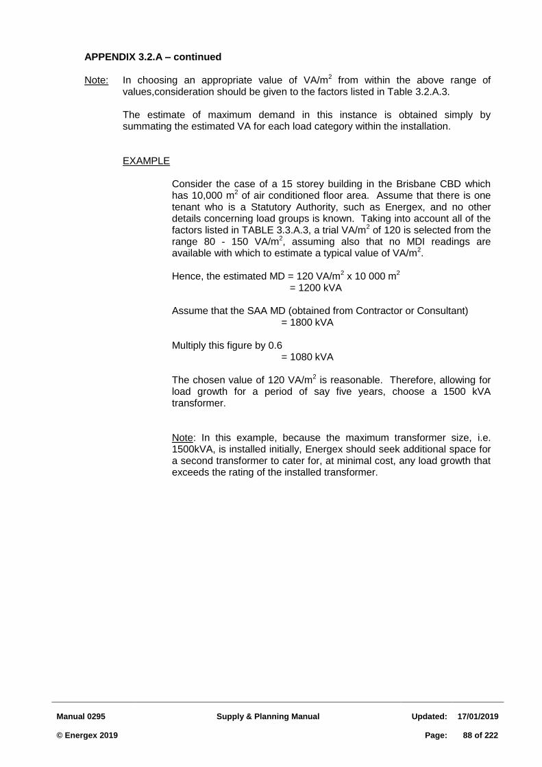
Manual 0295
Supply & Planning Manual
Updated:
17/01/2019 © Energex 2019
Page:
88 of 222
APPENDIX 3.2.A – continued Note: In choosing an appropriate value of VA/m2 from within the above range of
values,consideration should be given to the factors listed in Table 3.2.A.3. The estimate of maximum demand in this instance is obtained simply by
summating the estimated VA for each load category within the installation. EXAMPLE Consider the case of a 15 storey building in the Brisbane CBD which
has 10,000 m2 of air conditioned floor area. Assume that there is one tenant who is a Statutory Authority, such as Energex, and no other details concerning load groups is known. Taking into account all of the factors listed in TABLE 3.3.A.3, a trial VA/m2 of 120 is selected from the range 80 - 150 VA/m2, assuming also that no MDI readings are available with which to estimate a typical value of VA/m2.
Hence, the estimated MD = 120 VA/m2 x 10 000 m2 = 1200 kVA Assume that the SAA MD (obtained from Contractor or Consultant) = 1800 kVA Multiply this figure by 0.6 = 1080 kVA The chosen value of 120 VA/m2 is reasonable. Therefore, allowing for
load growth for a period of say five years, choose a 1500 kVA transformer.
Note: In this example, because the maximum transformer size, i.e.
1500kVA, is installed initially, Energex should seek additional space for a second transformer to cater for, at minimal cost, any load growth that exceeds the rating of the installed transformer.
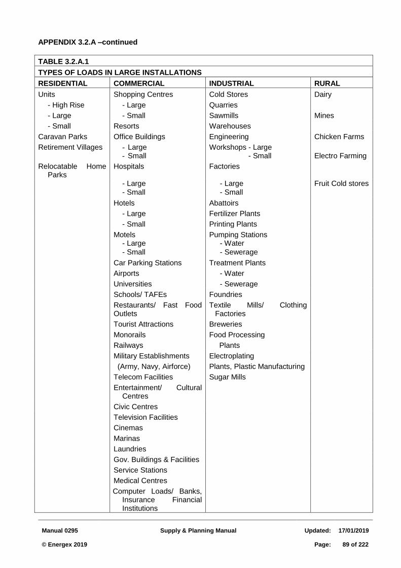
Manual 0295
Supply & Planning Manual
Updated:
17/01/2019 © Energex 2019
Page:
89 of 222
APPENDIX 3.2.A –continued
TABLE 3.2.A.1
TYPES OF LOADS IN LARGE INSTALLATIONS
RESIDENTIAL COMMERCIAL INDUSTRIAL RURAL
Units Shopping Centres Cold Stores Dairy
- High Rise - Large Quarries
- Large - Small Sawmills Mines
- Small Resorts Warehouses
Caravan Parks Office Buildings Engineering Chicken Farms
Retirement Villages - Large - Small
Workshops - Large - Small
Electro Farming
Relocatable Home Parks
Hospitals Factories
- Large - Large Fruit Cold stores
- Small - Small
Hotels Abattoirs
- Large Fertilizer Plants
- Small Printing Plants
Motels Pumping Stations - Large - Water
- Small - Sewerage
Car Parking Stations Treatment Plants
Airports - Water
Universities - Sewerage
Schools/ TAFEs Foundries
Restaurants/ Fast Food Outlets
Textile Mills/ Clothing Factories
Tourist Attractions Breweries
Monorails Food Processing
Railways Plants
Military Establishments Electroplating
(Army, Navy, Airforce) Plants, Plastic Manufacturing
Telecom Facilities Sugar Mills
Entertainment/ Cultural Centres
Civic Centres
Television Facilities
Cinemas
Marinas
Laundries
Gov. Buildings & Facilities
Service Stations
Medical Centres
Computer Loads/ Banks, Insurance Financial Institutions
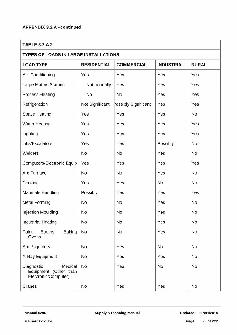
Manual 0295
Supply & Planning Manual
Updated:
17/01/2019 © Energex 2019
Page:
90 of 222
APPENDIX 3.2.A –continued
TABLE 3.2.A.2
TYPES OF LOADS IN LARGE INSTALLATIONS
LOAD TYPE RESIDENTIAL COMMERCIAL INDUSTRIAL RURAL
Air Conditioning Yes Yes Yes Yes
Large Motors Starting Not normally Yes Yes Yes
Process Heating No No Yes Yes
Refrigeration Not Significant Possibly Significant Yes Yes
Space Heating Yes Yes Yes No
Water Heating Yes Yes Yes Yes
Lighting Yes Yes Yes Yes
Lifts/Escalators Yes Yes Possibly No
Welders No No Yes No
Computers/Electronic Equip Yes Yes Yes Yes
Arc Furnace No No Yes No
Cooking Yes Yes No No
Materials Handling Possibly Yes Yes Yes
Metal Forming No No Yes No
Injection Moulding No No Yes No
Industrial Heating No No Yes No
Paint Booths, Baking Ovens
No No Yes No
Arc Projectors No Yes No No
X-Ray Equipment No Yes Yes No
Diagnostic Medical Equipment (Other than Electronic/Computer)
No Yes No No
Cranes No Yes Yes No
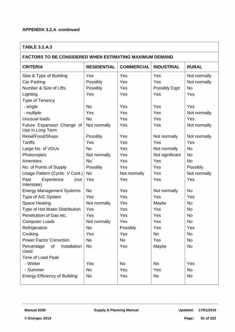
Manual 0295
Supply & Planning Manual
Updated:
17/01/2019 © Energex 2019
Page:
91 of 222
APPENDIX 3.2.A -continued
TABLE 3.2.A.3
FACTORS TO BE CONSIDERED WHEN ESTIMATING MAXIMUM DEMAND
CRITERIA RESIDENTIAL COMMERCIAL INDUSTRIAL RURAL
Size & Type of Building Yes Yes Yes Not normally
Car Parking Possibly Yes Yes Not normally
Number & Size of Lifts Possibly Yes Possibly Eqpt No
Lighting Yes Yes Yes Yes
Type of Tenancy
- single No Yes Yes Yes
- multiple Yes Yes Yes Not normally
Unusual loads No Yes Yes Yes
Future Expansion Change of Use in Long Term
Not normally Yes Yes Not normally
Retail/Food/Shops Possibly Yes Not normally Not normally
Tariffs Yes Yes Yes Yes
Large No. of VDUs No Yes Not normally No
Photocopies Not normally Yes Not significant No
Amenities No Yes Yes No
No. of Points of Supply Possibly Yes Yes Possibly
Usage Pattern (Cyclic V Cont.) No Not normally Yes Not normally
Past Experience (not Interstate)
Yes Yes Yes Yes
Energy Management Systems No Yes Not normally No
Type of A/C System Yes Yes Yes Yes
Space Heating Not normally Yes Maybe No
Type of Hot Water Distribution Yes Yes Yes No
Penetration of Gas etc. Yes Yes Yes No
Computer Loads Not normally Yes Yes No
Refrigeration No Possibly Yes Yes
Cooking Yes Yes No No
Power Factor Correction No No Yes No
Percentage of Installation Used
No Yes Maybe No
Time of Load Peak
- Winter
Yes
No
No
Yes
- Summer No Yes Yes No
Energy Efficiency of Building No Yes No No
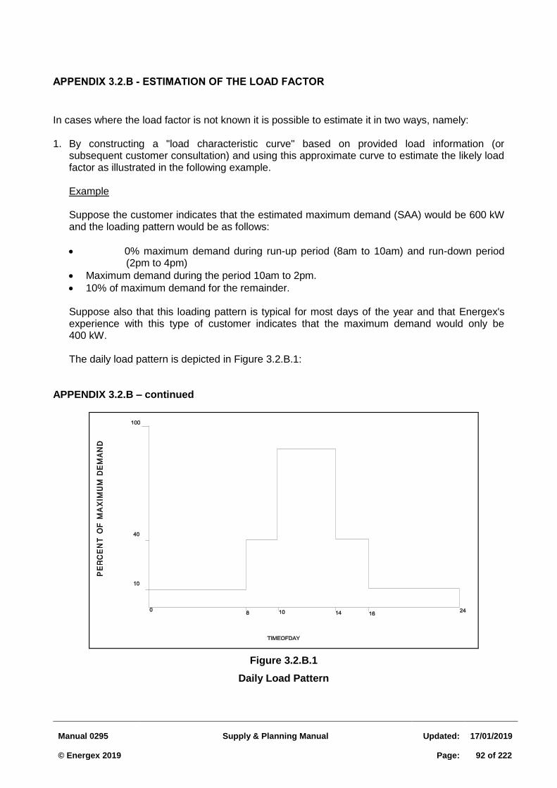
Manual 0295
Supply & Planning Manual
Updated:
17/01/2019 © Energex 2019
Page:
92 of 222
APPENDIX 3.2.B - ESTIMATION OF THE LOAD FACTOR
In cases where the load factor is not known it is possible to estimate it in two ways, namely: 1. By constructing a "load characteristic curve" based on provided load information (or
subsequent customer consultation) and using this approximate curve to estimate the likely load factor as illustrated in the following example.
Example
Suppose the customer indicates that the estimated maximum demand (SAA) would be 600 kW and the loading pattern would be as follows:
0% maximum demand during run-up period (8am to 10am) and run-down period (2pm to 4pm)
Maximum demand during the period 10am to 2pm.
10% of maximum demand for the remainder. Suppose also that this loading pattern is typical for most days of the year and that Energex's experience with this type of customer indicates that the maximum demand would only be 400 kW. The daily load pattern is depicted in Figure 3.2.B.1:
APPENDIX 3.2.B – continued
Figure 3.2.B.1
Daily Load Pattern
Manual 0295
Supply & Planning Manual
Updated:
17/01/2019 © Energex 2019
Page:
93 of 222
The total energy consumed in a 24 hour period is: energy consumed in period 12 midnight - 8 am + energy consumed in period 8 am
- 10 am + energy consumed in period 10 am - 2 pm + energy consumed in period 2 pm - 4 pm + energy consumed in period 4 pm - 12 midnight.
OR (0.1 x 400 x 8) + (0.4 x 400 x 2) + (400 x 4) + (0.4 x 400 x 2) + (0.1 x 400 x 8)
kWh. = 2 880 kWh. The total energy consumed in a 24 hour period if all demand was at 100% is therefore: 400 x 24 kWh = 9 600 kWh 2 800 Hence, Load Factor = = 0.3 9 600 Since the loading pattern is repeated, i.e. the same every day, the average monthly and
yearly load factors are the same as the average daily load factor. 2. Using a load characteristic curve that is typical of the type of customer being considered.
Alternatively, using a curve that closely approximates what the perceived load shape would be will also give acceptable results. This method is illustrated in the following example.
Example Suppose that the customer has a maximum demand, assessed by Energex, of 300 kW and
that the daily load characteristic curve is similar to that depicted in Figure 3.2.B.2. Suppose also that this loading pattern is typical for most days of the year. Once again the total energy consumed in a 24 hour period is the area under the curve in Figure 3.2.B.2. There are numerous methods of estimating this area; however, the simplest (keeping in mind that the curve is made up of a plot of half hourly maximum demands) and quickest is to divide the curve into half hourly periods or plot it out on squared graph paper. Once this has been done, pick the most likely maximum demand for each half hour period and calculate the area in each case as shown below.
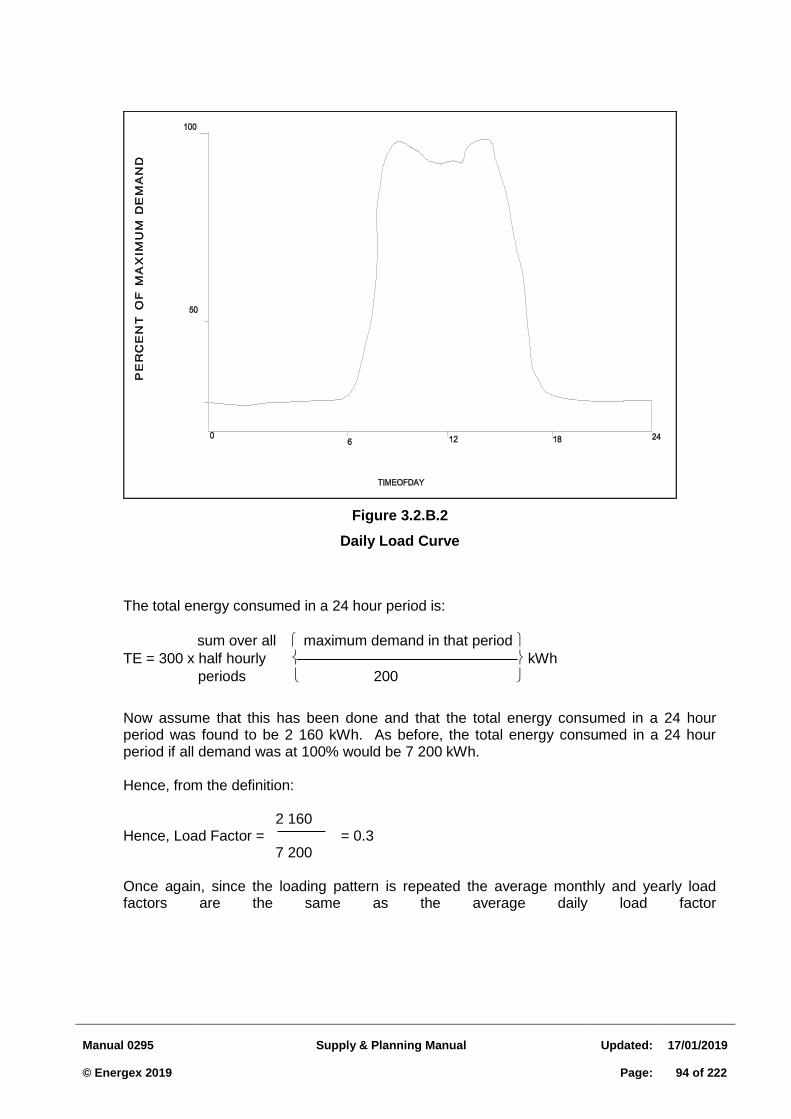
Manual 0295
Supply & Planning Manual
Updated:
17/01/2019 © Energex 2019
Page:
94 of 222
The total energy consumed in a 24 hour period is:
sum over all maximum demand in that period
TE = 300 x half hourly kWh
periods 200
Now assume that this has been done and that the total energy consumed in a 24 hour period was found to be 2 160 kWh. As before, the total energy consumed in a 24 hour period if all demand was at 100% would be 7 200 kWh.
Hence, from the definition: 2 160
Hence, Load Factor = = 0.3 7 200 Once again, since the loading pattern is repeated the average monthly and yearly load
factors are the same as the average daily load factor
Figure 3.2.B.2
Daily Load Curve
Manual 0295
Supply & Planning Manual
Updated:
17/01/2019 © Energex 2019
Page:
95 of 222
3.3 LOW VOLTAGE SYSTEM DESIGN AND PLANNING
3.3.1 Introduction
One of the primary considerations when planning an LV distribution network is to ensure that adequate voltage levels are maintained for all customers along an LV distributor at all times throughout the life of the LV network. In order to achieve this, accurate voltage drop and rise (with solar PV) calculations should be carried out, at the design stage, on the LV distributor
This chapter describes a method of calculating voltage drops along LV residential distribution networks and specifies maximum allowable voltage drops for design purposes to satisfy the statutory maximum and minimum voltage requirements.
3.3.2 Background
The low voltage network is one of the most important segment of the total Electricity Supply Industry. It represents the direct interface with most of our customers and accounts for the majority of the Industry's source of income.
The Electricity (Voltage Limits) Amendment Regulation 2017 has now allowed the adoption of AS60038:2012 requirements, which is 230V +10%, -6%. Up until October 2018, Queensland utilities were required to meet the previously regulated values of 240 volts ± 6%.
Voltage levels outside these limits may result in unacceptable supply conditions causing problems such as dim lights, blown lamps, TV or computer problems etc., resulting in customer complaints.
The factors influencing the overall distribution voltage regulation are:
(a) 11 kV System
1. 11 kV zone substation busbar voltage (Voltage/Line Drop Compensation System).
2. Feeder load.
3. 11 kV line regulation (depends on line impedance and load type).
4. Distribution transformer regulation (depends on transformer impedance and load).
5. Distribution transformer tap setting.
6. Unbalance on the 11 kV network.
(b) LV System
1. After Diversity Maximum Demand (ADMD) – depends on size and type of individual customer's diversified load.
2. Diversity Factor (varies with number of customers).
Manual 0295
Supply & Planning Manual
Updated:
17/01/2019 © Energex 2019
Page:
96 of 222
3. Unbalance Factor (varies with number of customers and phase balancing installation
techniques).
4. Line and Cable impedance (varies with the type, operating temperature and size of conductor/cable and load).
5. Load Control System for controllable loads (affects load factor, load peak and ADMD).
6. Number, size and phase distribution of solar PV systems connected to the network
LV regulation is influenced by the 11 kV voltage regulation. Any large variation in the 11 kV regulation will have to be compensated for in the LV system. An alteration to the tap setting of a distribution transformer may not effectively overcome a high variation in the 11 kV regulation and thus does not necessarily overcome over or under low voltage conditions.
Solar PV systems can cause a rise in the network voltage, particularly for large systems (above 3 kVA single phase and 15 kVA 3 phase) and when combined with long runs of LV conductor.
LV design in Energex is carried out using a PC based computer program called "LVDROP". Details on using this package are included in the LVDROP manual.
The parameters affecting LV Voltage Drop calculations are:
1. Balancing of Loads 2. After Diversity Maximum Demand 3. Diversity Factor 4. Conductor and Cable Impedance 5. Voltage at Distribution Transformer Secondary. 6. Length of Conductors/Cables.
Each of these parameters is described in the following sections.
Balancing of Loads 3.3.2.1
Overview
It is not possible to achieve perfect load balance between all three phases of an LV distributor supplying single phase domestic customers, despite connecting an equal number of customers to each phase.
This is due to the random variation in the magnitude of each connected load with time, resulting in unequal loads on the different phases of the distributor. This unbalance phase loading causes a current to flow in the neutral conductor of the distributor and a corresponding voltage drop in the neutral.
Certain areas in Energex have unbalance problems caused by various factors including LV load unbalance. Effective customer load balancing will reduce this problem.
Manual 0295
Supply & Planning Manual
Updated:
17/01/2019 © Energex 2019
Page:
97 of 222
The effects of unbalance are varied and a balancing policy will ensure minimisation of:
voltage and current unbalance between phases
shock and tingle complaints
excessive neutral current
overheating of distribution transformers
nuisance tripping and/or damage to induction motors
LV losses. Principles of Load Balancing The following assumptions are made when simple load balancing is performed:
1. Each domestic customer has the same load. 2. Distance between service tee offs in underground systems or span lengths in
overhead systems are equal. To minimise the effect of unbalance in an LV distributor it is therefore imperative that special attention be given to the selection of phase connections for individual customers. Nominated phase connections are to be shown on the subdivision works plan.
Voltage drop in each line segment is the product of the current and the impedance of the line segment. Impedance is a function of length of the line segment.
In order to arrive at a balanced condition, the sum of the moments of each phase should be equal, or nearly so. The difference in moments between the phases is a measure of load and voltage unbalance.
Major appliances, such as hot water systems, electric cooking appliances, space cooling and/or heating appliances and solar PV systems can have a significant influence on load unbalance conditions.
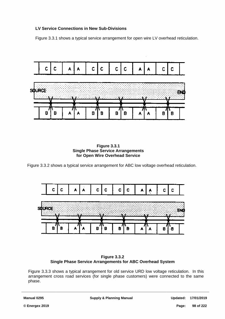
Manual 0295
Supply & Planning Manual
Updated:
17/01/2019 © Energex 2019
Page:
98 of 222
LV Service Connections in New Sub-Divisions Figure 3.3.1 shows a typical service arrangement for open wire LV overhead reticulation.
Figure 3.3.1
Single Phase Service Arrangements for Open Wire Overhead Service
Figure 3.3.2 shows a typical service arrangement for ABC low voltage overhead reticulation.
Figure 3.3.2
Single Phase Service Arrangements for ABC Overhead System
Figure 3.3.3 shows a typical arrangement for old service URD low voltage reticulation. In this arrangement cross road services (for single phase customers) were connected to the same phase.
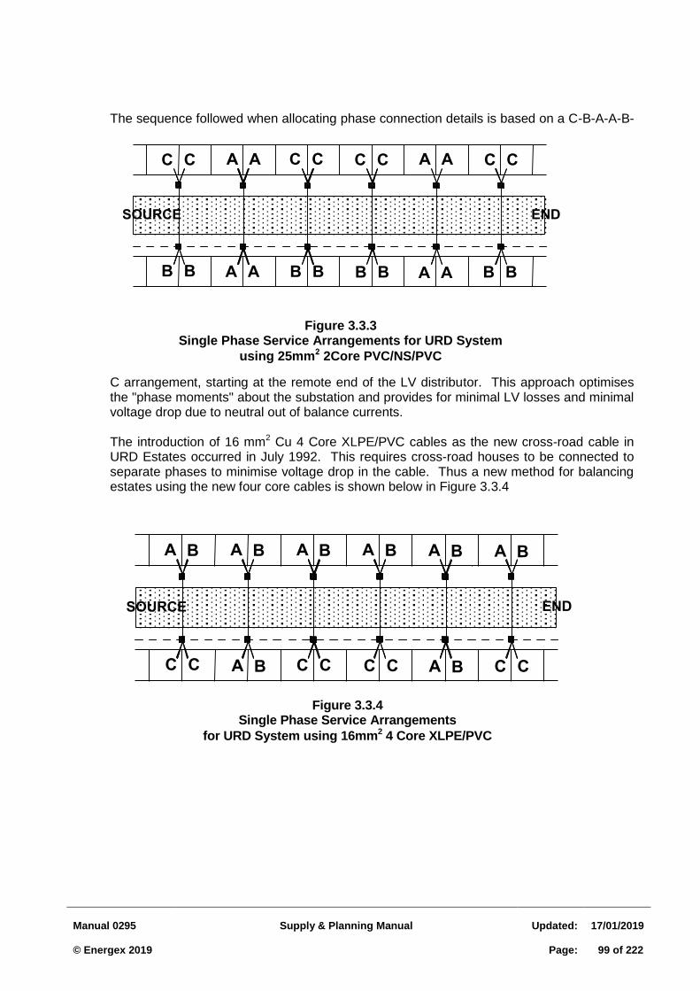
Manual 0295
Supply & Planning Manual
Updated:
17/01/2019 © Energex 2019
Page:
99 of 222
A BC C
A B A B A B A B A B A B
C CC C A B C C
SOURCE END
Figure 3.3.4 Single Phase Service Arrangements
for URD System using 16mm2 4 Core XLPE/PVC
The sequence followed when allocating phase connection details is based on a C-B-A-A-B-
C arrangement, starting at the remote end of the LV distributor. This approach optimises the "phase moments" about the substation and provides for minimal LV losses and minimal voltage drop due to neutral out of balance currents. The introduction of 16 mm2 Cu 4 Core XLPE/PVC cables as the new cross-road cable in URD Estates occurred in July 1992. This requires cross-road houses to be connected to separate phases to minimise voltage drop in the cable. Thus a new method for balancing estates using the new four core cables is shown below in Figure 3.3.4
A A
B B B B B B B B
C C C C C C C C
A A
A A
A A
SOURCE END
Figure 3.3.3
Single Phase Service Arrangements for URD System
using 25mm2 2Core PVC/NS/PVC
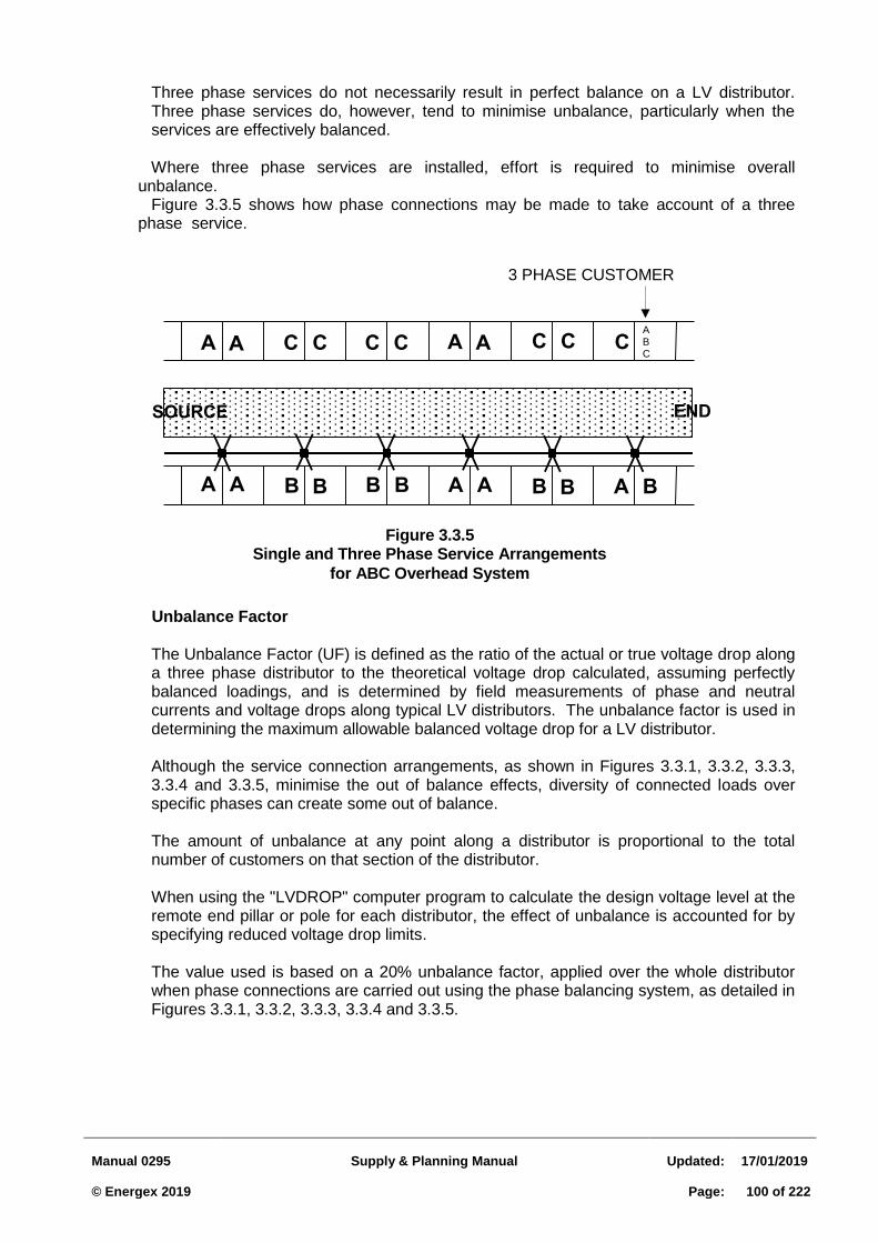
Manual 0295
Supply & Planning Manual
Updated:
17/01/2019 © Energex 2019
Page:
100 of 222
B BA A
A A C C
B B B B A B
SOURCE END
C CC C A A CABC
A A
Figure 3.3.5
Single and Three Phase Service Arrangements
for ABC Overhead System
Three phase services do not necessarily result in perfect balance on a LV distributor. Three phase services do, however, tend to minimise unbalance, particularly when the services are effectively balanced.
Where three phase services are installed, effort is required to minimise overall unbalance. Figure 3.3.5 shows how phase connections may be made to take account of a three phase service.
Unbalance Factor
The Unbalance Factor (UF) is defined as the ratio of the actual or true voltage drop along a three phase distributor to the theoretical voltage drop calculated, assuming perfectly balanced loadings, and is determined by field measurements of phase and neutral currents and voltage drops along typical LV distributors. The unbalance factor is used in determining the maximum allowable balanced voltage drop for a LV distributor.
Although the service connection arrangements, as shown in Figures 3.3.1, 3.3.2, 3.3.3, 3.3.4 and 3.3.5, minimise the out of balance effects, diversity of connected loads over specific phases can create some out of balance.
The amount of unbalance at any point along a distributor is proportional to the total number of customers on that section of the distributor.
When using the "LVDROP" computer program to calculate the design voltage level at the remote end pillar or pole for each distributor, the effect of unbalance is accounted for by specifying reduced voltage drop limits.
The value used is based on a 20% unbalance factor, applied over the whole distributor when phase connections are carried out using the phase balancing system, as detailed in Figures 3.3.1, 3.3.2, 3.3.3, 3.3.4 and 3.3.5.
3 PHASE CUSTOMER
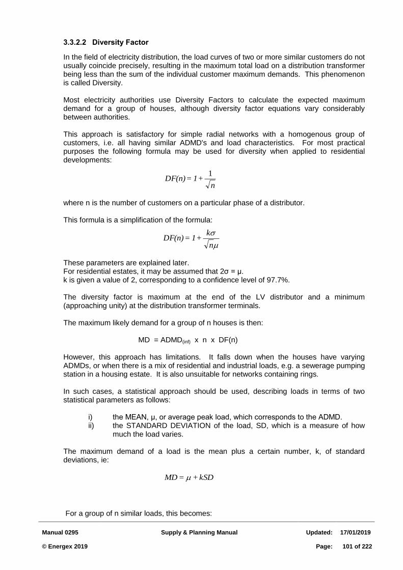
Manual 0295
Supply & Planning Manual
Updated:
17/01/2019 © Energex 2019
Page:
101 of 222
n+1=DF(n)
1
n
k+1=DF(n)
Diversity Factor 3.3.2.2
In the field of electricity distribution, the load curves of two or more similar customers do not usually coincide precisely, resulting in the maximum total load on a distribution transformer being less than the sum of the individual customer maximum demands. This phenomenon is called Diversity. Most electricity authorities use Diversity Factors to calculate the expected maximum demand for a group of houses, although diversity factor equations vary considerably between authorities. This approach is satisfactory for simple radial networks with a homogenous group of customers, i.e. all having similar ADMD's and load characteristics. For most practical purposes the following formula may be used for diversity when applied to residential developments:
where n is the number of customers on a particular phase of a distributor.
This formula is a simplification of the formula:
These parameters are explained later. For residential estates, it may be assumed that 2σ = μ. k is given a value of 2, corresponding to a confidence level of 97.7%. The diversity factor is maximum at the end of the LV distributor and a minimum (approaching unity) at the distribution transformer terminals. The maximum likely demand for a group of n houses is then:
MD = ADMD(inf) x n x DF(n)
However, this approach has limitations. It falls down when the houses have varying ADMDs, or when there is a mix of residential and industrial loads, e.g. a sewerage pumping station in a housing estate. It is also unsuitable for networks containing rings. In such cases, a statistical approach should be used, describing loads in terms of two statistical parameters as follows:
i) the MEAN, μ, or average peak load, which corresponds to the ADMD. ii) the STANDARD DEVIATION of the load, SD, which is a measure of how
much the load varies.
The maximum demand of a load is the mean plus a certain number, k, of standard deviations, ie:
kSD+=MD
For a group of n similar loads, this becomes:
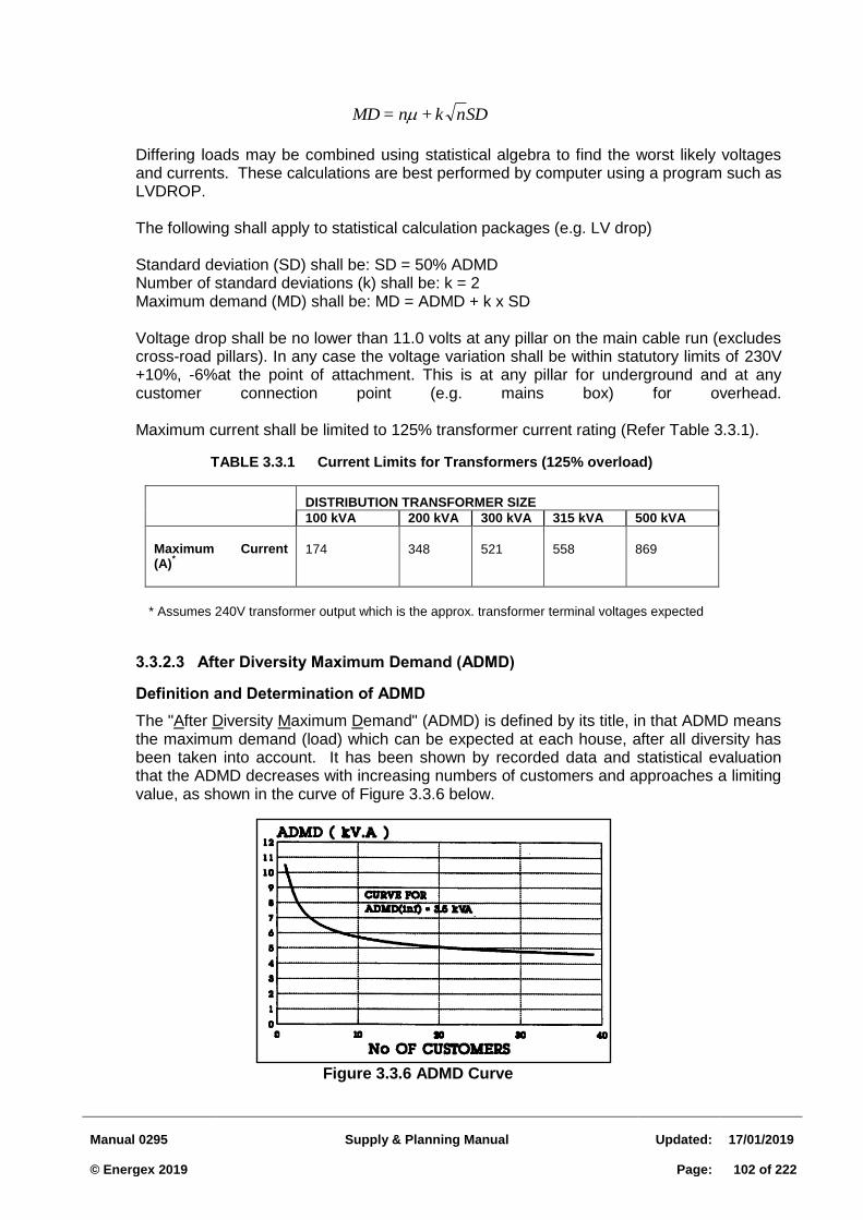
Manual 0295
Supply & Planning Manual
Updated:
17/01/2019 © Energex 2019
Page:
102 of 222
SDnk+n=MD
Differing loads may be combined using statistical algebra to find the worst likely voltages and currents. These calculations are best performed by computer using a program such as LVDROP. The following shall apply to statistical calculation packages (e.g. LV drop) Standard deviation (SD) shall be: SD = 50% ADMD Number of standard deviations (k) shall be: k = 2 Maximum demand (MD) shall be: MD = ADMD + k x SD Voltage drop shall be no lower than 11.0 volts at any pillar on the main cable run (excludes cross-road pillars). In any case the voltage variation shall be within statutory limits of 230V +10%, -6%at the point of attachment. This is at any pillar for underground and at any customer connection point (e.g. mains box) for overhead. Maximum current shall be limited to 125% transformer current rating (Refer Table 3.3.1).
TABLE 3.3.1 Current Limits for Transformers (125% overload)
DISTRIBUTION TRANSFORMER SIZE
100 kVA 200 kVA 300 kVA 315 kVA 500 kVA
Maximum Current (A)
*
174
348
521
558
869
* Assumes 240V transformer output which is the approx. transformer terminal voltages expected
After Diversity Maximum Demand (ADMD) 3.3.2.3
Definition and Determination of ADMD
The "After Diversity Maximum Demand" (ADMD) is defined by its title, in that ADMD means the maximum demand (load) which can be expected at each house, after all diversity has been taken into account. It has been shown by recorded data and statistical evaluation that the ADMD decreases with increasing numbers of customers and approaches a limiting value, as shown in the curve of Figure 3.3.6 below.
Figure 3.3.6 ADMD Curve
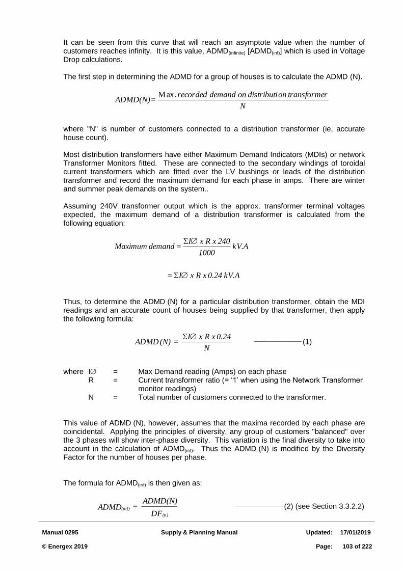
Manual 0295
Supply & Planning Manual
Updated:
17/01/2019 © Energex 2019
Page:
103 of 222
It can be seen from this curve that will reach an asymptote value when the number of customers reaches infinity. It is this value, ADMD(infinite) [ADMD(inf)] which is used in Voltage Drop calculations. The first step in determining the ADMD for a group of houses is to calculate the ADMD (N).
N
rtransforme ondistributi on demand recorded . = ADMD(N)Max
where "N" is number of customers connected to a distribution transformer (ie, accurate house count). Most distribution transformers have either Maximum Demand Indicators (MDIs) or network Transformer Monitors fitted. These are connected to the secondary windings of toroidal current transformers which are fitted over the LV bushings or leads of the distribution transformer and record the maximum demand for each phase in amps. There are winter and summer peak demands on the system.. Assuming 240V transformer output which is the approx. transformer terminal voltages expected, the maximum demand of a distribution transformer is calculated from the following equation:
kV.A 0.24 x R x I =
kV.A 1000
240 x R x I = demand Maximum
Thus, to determine the ADMD (N) for a particular distribution transformer, obtain the MDI readings and an accurate count of houses being supplied by that transformer, then apply the following formula:
N
0.24 x R x I = (N) ADMD
__________________ (1)
where I = Max Demand reading (Amps) on each phase R = Current transformer ratio (= ‘1’ when using the Network Transformer
monitor readings) N = Total number of customers connected to the transformer.
This value of ADMD (N), however, assumes that the maxima recorded by each phase are coincidental. Applying the principles of diversity, any group of customers "balanced" over the 3 phases will show inter-phase diversity. This variation is the final diversity to take into account in the calculation of ADMD(inf). Thus the ADMD (N) is modified by the Diversity Factor for the number of houses per phase.
The formula for ADMD(inf) is then given as:
DF
ADMD(N) = ADMD
(n)
(inf) __________________ (2) (see Section 3.3.2.2)
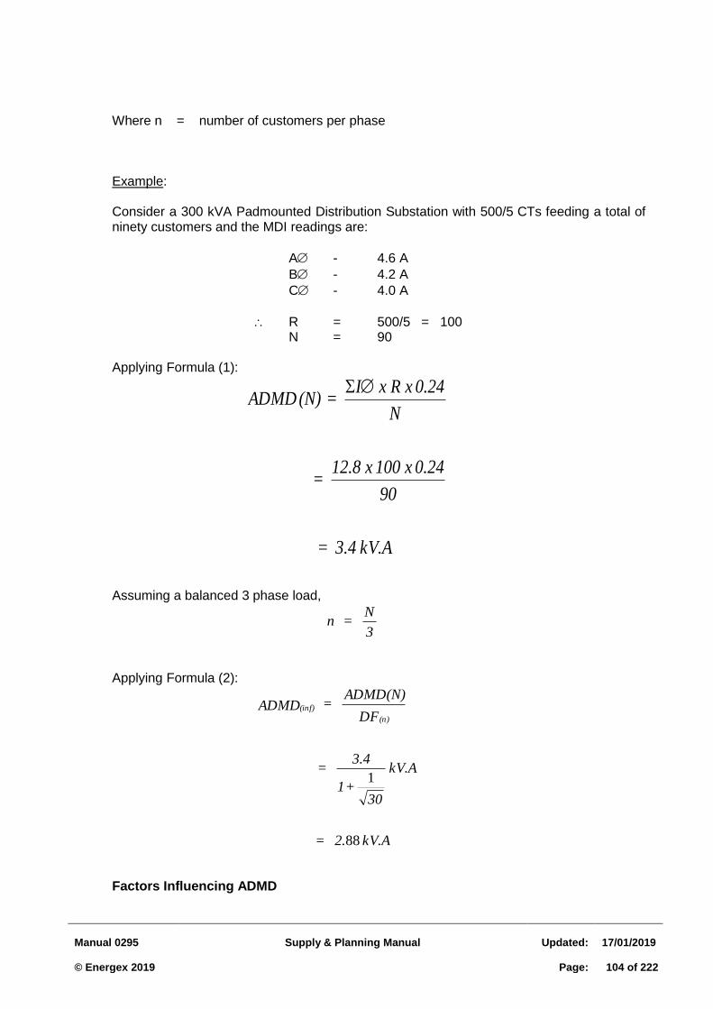
Manual 0295
Supply & Planning Manual
Updated:
17/01/2019 © Energex 2019
Page:
104 of 222
Where n = number of customers per phase Example: Consider a 300 kVA Padmounted Distribution Substation with 500/5 CTs feeding a total of ninety customers and the MDI readings are:
A - 4.6 A
B - 4.2 A
C - 4.0 A
R = 500/5 = 100 N = 90
Applying Formula (1):
kV.A 3.4 =
90
0.24 x 100 x 12.8 =
N
0.24 x R x I = (N) ADMD
Assuming a balanced 3 phase load,
3
N = n
Applying Formula (2):
kV.A 2. =
kV.A
30 + 1
3.4 =
DF
ADMD(N) = ADMD
(n)
(inf)
88
1
Factors Influencing ADMD
Manual 0295
Supply & Planning Manual
Updated:
17/01/2019 © Energex 2019
Page:
105 of 222
ADMD is the most critical variable factor in LV system design as its accurate selection directly affects the optimum costs of an installation and quality of supply. An under-statement of ADMD may result in a future voltage problem. An over-statement of ADMD usually results in over-design with the resultant unnecessary increase in capital costs. ADMD is influenced by several factors including the following: 1. Size and type of dwelling, ie low income house, up-market canal estate house, town
house etc. 2. Presence of alternative energy sources, ie gas cooking, gas space heating, gas hot
water, solar hot water etc. 3. Presence of air conditioners, ie space cooling and/or heating. 4. Presence of solar PV systems 5. Load factor (varies with socio-economic groups), ie-disposable income affects life style
etc. 6. Type and size of electric water heater, i.e. storage or instantaneous, element rating,
controlled or uncontrolled and tariff selection. For example, a subdivision may totally include Housing Commission dwellings which may all have identical hot water systems connected to the night rate tariff. The resultant effect is a maximum demand in the order of 3.6 kV.A/house, ie – the typical rating of the hot water system, which may be the maximum load seen by the supply transformer.
The LV winter peak demand typically occurs for up to four hours, ie between 5.30 pm and 9.30 pm, over approximately two months a year (July–August). The summer peak load is temperature dependent and occurs for up to 4 hours from 2 pm to 6 pm over the December to February period. LV design is based on statistical methods of diversity and unbalance, ie Diversity Factors and Unbalance Factors, in association with variations in maximum demands which can be influenced by the effects of space cooling and heating, hot water heaters, alternative energy sources etc. Energex's URD system is based on a fully ducted system with above ground terminations in pillars. This approach simplifies testing and fault finding with a relative low cost of augmentation to overcome adverse voltage conditions. It is therefore important that emphasis is applied to the optimum selection of ADMD. The influencing factors, as listed above, should be evaluated for each individual estate to assist in the selection of optimum ADMD or maximum load condition for voltage drop calculations. ADMD Design Values Recent years have seen significant growth in residential electricity loads due to a range of factors including; dwelling size, style and density and increased customer reliance on whitegoods and air conditioning. These factors (particularly air conditioning) have significantly increased demand on the electricity network. Accordingly, After Diversity Maximum Demand (ADMD) has been revised as is shown in Table 3.3.2 below.
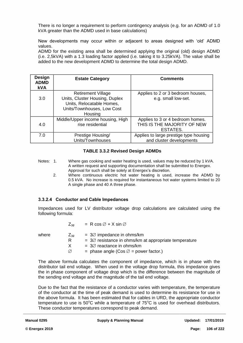
Manual 0295
Supply & Planning Manual
Updated:
17/01/2019 © Energex 2019
Page:
106 of 222
There is no longer a requirement to perform contingency analysis (e.g. for an ADMD of 1.0 kVA greater than the ADMD used in base calculations) New developments may occur within or adjacent to areas designed with ‘old’ ADMD values. ADMD for the existing area shall be determined applying the original (old) design ADMD (i.e. 2,5kVA) with a 1.3 loading factor applied (i.e. taking it to 3.25kVA). The value shall be added to the new development ADMD to determine the total design ADMD.
Design ADMD kVA
Estate Category Comments
3.0
Retirement Village Units, Cluster Housing, Duplex
Units, Relocatable Homes, Units/Townhouses, Low Cost
Housing
Applies to 2 or 3 bedroom houses, e.g. small low-set.
4.0
Middle/Upper income housing, High rise residential
Applies to 3 or 4 bedroom homes. THIS IS THE MAJORITY OF NEW
ESTATES.
7.0
Prestige Housing/ Units/Townhouses
Applies to large prestige type housing and cluster developments
TABLE 3.3.2 Revised Design ADMDs
Notes: 1. Where gas cooking and water heating is used, values may be reduced by 1 kVA.
A written request and supporting documentation shall be submitted to Energex. Approval for such shall be solely at Energex’s discretion.
2. Where continuous electric hot water heating is used, increase the ADMD by 0.5 kVA. No increase is required for instantaneous hot water systems limited to 20 A single phase and 40 A three phase.
Conductor and Cable Impedances 3.3.2.4
Impedances used for LV distributor voltage drop calculations are calculated using the following formula:
Z30/ = R cos + X sin
where Z30/ = 3 impedance in ohms/km
R = 3 resistance in ohms/km at appropriate temperature
X = 3 reactance in ohms/km
= phase angle (Cos = power factor.)
The above formula calculates the component of impedance, which is in phase with the distributor tail end voltage. When used in the voltage drop formula, this impedance gives the in phase component of voltage drop which is the difference between the magnitude of the sending end voltage and the magnitude of the tail end voltage. Due to the fact that the resistance of a conductor varies with temperature, the temperature of the conductor at the time of peak demand is used to determine its resistance for use in the above formula. It has been estimated that for cables in URD, the appropriate conductor temperature to use is 50oC while a temperature of 75oC is used for overhead distributors. These conductor temperatures correspond to peak demand.
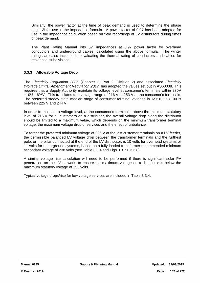
Manual 0295
Supply & Planning Manual
Updated:
17/01/2019 © Energex 2019
Page:
107 of 222
Similarly, the power factor at the time of peak demand is used to determine the phase
angle for use in the impedance formula. A power factor of 0.97 has been adopted for use in the impedance calculation based on field recordings of LV distributors during times of peak demand.
The Plant Rating Manual lists 3 impedances at 0.97 power factor for overhead conductors and underground cables, calculated using the above formula. The winter ratings are also included for evaluating the thermal rating of conductors and cables for residential subdivisions.
3.3.3 Allowable Voltage Drop
The Electricity Regulation 2006 (Chapter 2, Part 2, Division 2) and associated Electricity (Voltage Limits) Amendment Regulation 2017, has adopted the values set out in AS60038. This requires that a Supply Authority maintain its voltage level at consumer’s terminals within 230V +10%, -6%V. This translates to a voltage range of 216 V to 253 V at the consumer’s terminals. The preferred steady state median range of consumer terminal voltages in AS61000.3.100 is between 225 V and 244 V.
In order to maintain a voltage level, at the consumer’s terminals, above the minimum statutory level of 216 V for all customers on a distributor, the overall voltage drop along the distributor should be limited to a maximum value, which depends on the minimum transformer terminal voltage, the maximum voltage drop of services and the effect of unbalance.
To target the preferred minimum voltage of 225 V at the last customer terminals on a LV feeder, the permissible balanced LV voltage drop between the transformer terminals and the furthest pole, or the pillar connected at the end of the LV distributor, is 10 volts for overhead systems or 11 volts for underground systems, based on a fully loaded transformer recommended minimum secondary voltage of 238 volts (see Table 3.3.4 and Figs 3.3.7 / 3.3.8).
A similar voltage rise calculation will need to be performed if there is significant solar PV penetration on the LV network, to ensure the maximum voltage on a distributor is below the maximum statutory voltage of 253 volts.
Typical voltage drops/rise for low voltage services are included in Table 3.3.4.
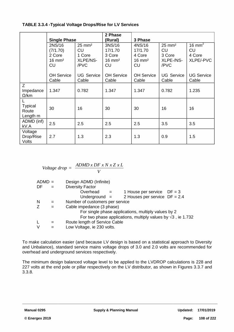
Manual 0295
Supply & Planning Manual
Updated:
17/01/2019 © Energex 2019
Page:
108 of 222
V
L x Zx N x DF x ADMD = drop Voltage
TABLE 3.3.4 -Typical Voltage Drops/Rise for LV Services
Single Phase
2 Phase (Rural)
3 Phase
2NS/16 (7/1.70) 2 Core 16 mm² CU OH Service Cable
25 mm² CU 1 Core XLPE/NS-/PVC UG Service Cable
3NS/16 17/1.70 3 Core 16 mm² CU OH Service Cable
4NS/16 17/1.70 4 Core 16 mm² CU OH Service Cable
25 mm² CU 3 Core XLPE-/NS-/PVC UG Service Cable
16 mm2 CU 4 Core XLPE/-PVC UG Service Cable
Z Impedance Ω/km
1.347 0.782 1.347 1.347 0.782 1.235
L Typical Route Length m
30 16 30 30 16 16
ADMD (inf) kV.A
2.5 2.5 2.5 2.5 3.5 3.5
Voltage Drop/Rise Volts
2.7 1.3 2.3 1.3 0.9 1.5
ADMD = Design ADMD (Infinite) DF = Diversity Factor
Overhead = 1 House per service DF = 3 Underground = 2 Houses per service DF = 2.4 N = Number of customers per service Z = Cable impedance (3 phase) For single phase applications, multiply values by 2
For two phase applications, multiply values by 3 , ie 1.732 L = Route length of Service Cable V = Low Voltage, ie 230 volts.
To make calculation easier (and because LV design is based on a statistical approach to Diversity and Unbalance), standard service mains voltage drops of 3.0 and 2.0 volts are recommended for overhead and underground services respectively. The minimum design balanced voltage level to be applied to the LVDROP calculations is 228 and 227 volts at the end pole or pillar respectively on the LV distributor, as shown in Figures 3.3.7 and 3.3.8.

Manual 0295
Supply & Planning Manual
Updated:
17/01/2019 © Energex 2019
Page:
109 of 222
Figure 3.3.7
Minimum Design Balanced Voltage Level Underground System
Transformer
(Output 238 volts) Last Pillar on Main Distributor
(Design Balanced Voltage
Level – 227 volts)
Consumers
Terminals ~225V
(Min Statutory
volts 216)
Consumers
Mains
25 sq mm CU XLPE
Cross Road
Service Cable
(Typical Voltage
drop 2 volts)
16m
Road
Reserve
Figure 3.3.8
Minimum Design Balanced Voltage Level Overhead System
Transformer
(Output 238 volts)
Last Pole
(Design Balanced
Voltage Level =
228 volts)
Consumers
Terminals ~225V
(Min Statutory
volts 216)
Distributor
16 sq mm
Service Mains
(Typical Voltage
drop 3 volts)
16m
Road
Reserve
Road
With the high penetration of solar PV systems on the LV network, it is important that the correct voltage range be maintained at the transformer LV terminals to ensure the voltages to customers are within the regulated range. An understanding of the 11 kV voltage management practices is needed to determine the actual voltage levels at the distribution transformer secondary terminals. The preferred distribution transformer secondary voltage lies in the range 236-242 V, but this is depended on the 11 kV planning design and operating practices(voltage/line drop compensation schemes). Network Operations will produce a list of designated transformer taps for all distribution transformers across the network. Based on the objective of a design balanced voltage level, at the furthest LV pole or LV pillar, of 228 and 227 volts respectively (refer to Figures 3.3.7 and 3.3.8), the allowable balanced voltage drops for various transformer secondary full load voltage levels are included in Table 3.3.5.
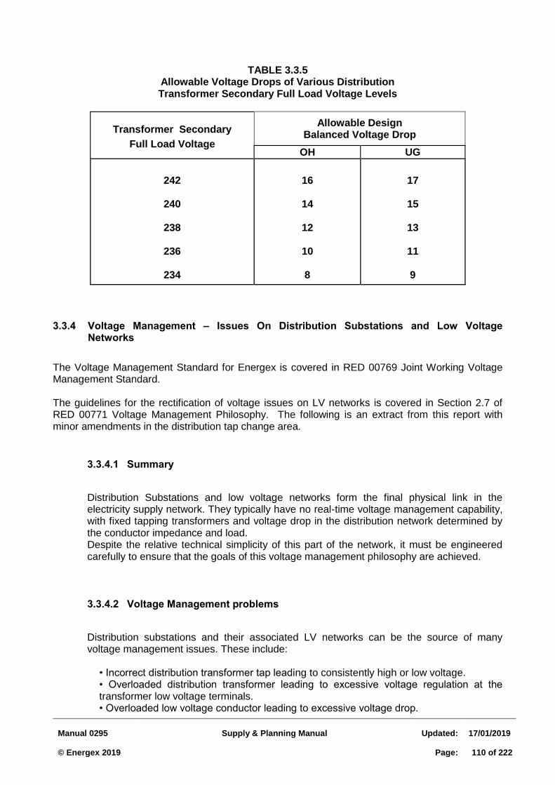
Manual 0295
Supply & Planning Manual
Updated:
17/01/2019 © Energex 2019
Page:
110 of 222
TABLE 3.3.5
Allowable Voltage Drops of Various Distribution Transformer Secondary Full Load Voltage Levels
Transformer Secondary
Full Load Voltage
Allowable Design Balanced Voltage Drop
OH UG
242
240
238
236
234
16
14
12
10
8
17
15
13
11
9
3.3.4 Voltage Management – Issues On Distribution Substations and Low Voltage Networks
The Voltage Management Standard for Energex is covered in RED 00769 Joint Working Voltage Management Standard. The guidelines for the rectification of voltage issues on LV networks is covered in Section 2.7 of RED 00771 Voltage Management Philosophy. The following is an extract from this report with minor amendments in the distribution tap change area.
Summary 3.3.4.1
Distribution Substations and low voltage networks form the final physical link in the electricity supply network. They typically have no real-time voltage management capability, with fixed tapping transformers and voltage drop in the distribution network determined by the conductor impedance and load. Despite the relative technical simplicity of this part of the network, it must be engineered carefully to ensure that the goals of this voltage management philosophy are achieved.
Voltage Management problems 3.3.4.2
Distribution substations and their associated LV networks can be the source of many voltage management issues. These include:
• Incorrect distribution transformer tap leading to consistently high or low voltage. • Overloaded distribution transformer leading to excessive voltage regulation at the transformer low voltage terminals. • Overloaded low voltage conductor leading to excessive voltage drop.
Manual 0295
Supply & Planning Manual
Updated:
17/01/2019 © Energex 2019
Page:
111 of 222
• Voltage regulation problems on the high voltage side (especially if voltage regulators installed along 11kV feeder). • Levels of solar PV leading to voltage rise above statutory limits in the middle of the day
Typical solutions to voltage management problems 3.3.4.3
Voltage management problems are often first identified at the low voltage level via a customer complaint. OS115 – Phase and MEN Voltage Investigations outlines the steps to follow when undertaking voltage investigations. Following appropriate logging of the customer’s installation as described in the Voltage Management Standard, a number of possible solutions to the problems identified can be employed.
Generically, the possible solutions, listed in approximate capital cost order, are:
• Balance the phase connection of the customer (solar PV systems and customer loads) • Adjust distribution transformer tap setting • Move LV links • Reconductor LV mains to reduce voltage drop • Upgrade the distribution transformer to avoid overloading • Install an additional distribution transformer • Modify solar PV system (reactive inverter or change in set point voltage)
Each of these possible solutions is discussed in more detail below.
In many cases more than one, or a combination of possible solutions would solve a customer’s issue. Care must be taken in choosing the appropriate solution to ensure that:
• the initial problem is adequately solved by the proposed solution, • any additional customer issues identified in the investigation are also solved, • a problem is not created for another customer, • the solution is adequate for expected needs for a minimum of five years, and • the lowest capital cost solution meeting the above criteria is chosen.
In the past, the practice of utilising “ring” circuits was adopted in many areas to assist in reducing voltage drop in the LV mains during high loads. Whilst some reduction in voltage drop is achieved, it can prove difficult to control the voltage in the circuit under all load conditions. Ring circuits can also reduce the effectiveness of the transformer LV fuse protection. Therefore, the practice of using “ring” circuits for new installations is no longer permitted. When modifying existing “ring” circuits, consideration should be given to breaking these “rings” where practical.
Balance the customer’s phase connection
In some cases a customer’s voltage problem could merely be caused by being connected to a phase with voltage outside the normal range. Low voltage systems with unbalanced phase currents not only produce voltage drop on the active conductor, but residual current in the neutral also contributes to a voltage drop in the neutral conductor.
In this case the simplest solution will be to move the customer to another phase. If the phase the customer is supplied from is heavily loaded causing excessive voltage drop, and the other phases have lighter loads, this may be the ideal solution. In many cases however, the
Manual 0295
Supply & Planning Manual
Updated:
17/01/2019 © Energex 2019
Page:
112 of 222
situation will be more complex and other customers on the same low voltage network will also have problems, regardless of whether they have complained or not.
If one customer is receiving voltage outside the normal range of a particular phase, it is possible that other customers supplied from that phase will have the same problem. Even if they have not complained, investigations should be carried out to ensure that the proposed solution will provide all customers on the low voltage network with adequate voltage.
Care should be taken to ensure that readings over at least a week are taken. Taking readings over a shorter term may give a misleading impression, so loads should be measured for in excess of 48 hours, or longer if necessary to display the impacts of any solar PV systems on the network.
Of course this solution does not apply to customers with three phase supply.
Distribution transformer tap setting
Distribution transformers must be set on a fixed tap ratio which is appropriate for all times of the day and all times of the year. The setting of this tap should be carried out as part of a tap plan. It should not be determined just be measuring voltage on the low voltage terminals at the time of commissioning.
Table 3.3.7 provides guidance in the selection of tap ratios for the Energex network. This table looks to take into account transformer terminal voltages under both peak load and no load conditions. There can be unique arrangements in some circumstances that may require a different tap setting to be selected (e.g. such as high penetration of distributed generation at the end of a Rural feeder) and these should be considered as part of a tap plan. There is a 2.5% difference in voltage for each tap change.
Move low voltage links
In some cases a voltage complaint will be able to be resolved simply by moving the position of LV network links. This has the effect of reducing the load on one distribution transformer and increasing it on the adjacent one. Potentially it can also move a customer with a voltage problem to an adjacent transformer.
Care should be taken when employing this solution that it does not merely move a problem from one place to another. This approach works best where the two transformers in question are relatively close together and one is heavily loaded while the other is lightly loaded.
As always, thorough investigation is needed prior to implementing a proposed solution.
Reconductor LV mains to reduce voltage drop
Reducing the impedance of the LV circuit by installing larger LV conductors can be an effective approach. This would usually be cheaper than an alternative solution involving installation of a transformer.
Care should be taken to ensure that this solution will be effective to cater for expected load growth for at least five years.
Upgrade the distribution transformer to avoid overloading
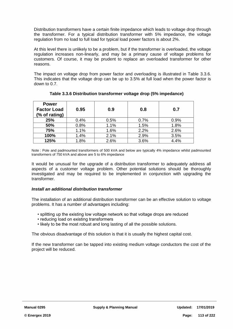
Manual 0295
Supply & Planning Manual
Updated:
17/01/2019 © Energex 2019
Page:
113 of 222
Distribution transformers have a certain finite impedance which leads to voltage drop through the transformer. For a typical distribution transformer with 5% impedance, the voltage regulation from no load to full load for typical load power factors is about 2%.
At this level there is unlikely to be a problem, but if the transformer is overloaded, the voltage regulation increases non-linearly, and may be a primary cause of voltage problems for customers. Of course, it may be prudent to replace an overloaded transformer for other reasons.
The impact on voltage drop from power factor and overloading is illustrated in Table 3.3.6. This indicates that the voltage drop can be up to 3.5% at full load when the power factor is down to 0.7.
Table 3.3.6 Distribution transformer voltage drop (5% impedance)
Power Factor Load (% of rating)
0.95
0.9
0.8
0.7
25% 0.4% 0.5% 0.7% 0.9%
50% 0.8% 1.1% 1.5% 1.8%
75% 1.1% 1.6% 2.2% 2.6%
100% 1.4% 2.1% 2.9% 3.5%
125% 1.8% 2.6% 3.6% 4.4%
Note : Pole and padmounted transformers of 500 kVA and below are typically 4% impedance whilst padmounted transformers of 750 kVA and above are 5 to 6% impedance
It would be unusual for the upgrade of a distribution transformer to adequately address all aspects of a customer voltage problem. Other potential solutions should be thoroughly investigated and may be required to be implemented in conjunction with upgrading the transformer.
Install an additional distribution transformer
The installation of an additional distribution transformer can be an effective solution to voltage problems. It has a number of advantages including:
• splitting up the existing low voltage network so that voltage drops are reduced • reducing load on existing transformers • likely to be the most robust and long lasting of all the possible solutions.
The obvious disadvantage of this solution is that it is usually the highest capital cost.
If the new transformer can be tapped into existing medium voltage conductors the cost of the project will be reduced.
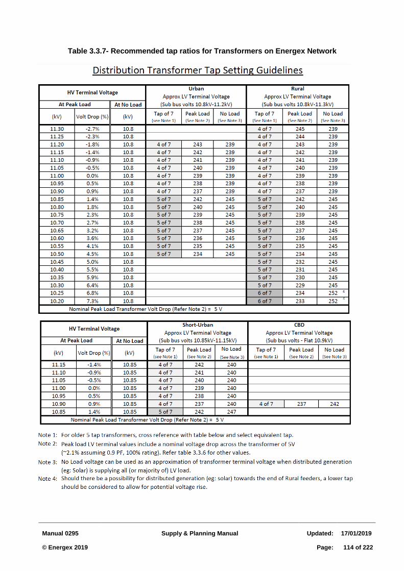
Manual 0295
Supply & Planning Manual
Updated:
17/01/2019 © Energex 2019
Page:
114 of 222
Table 3.3.7- Recommended tap ratios for Transformers on Energex Network
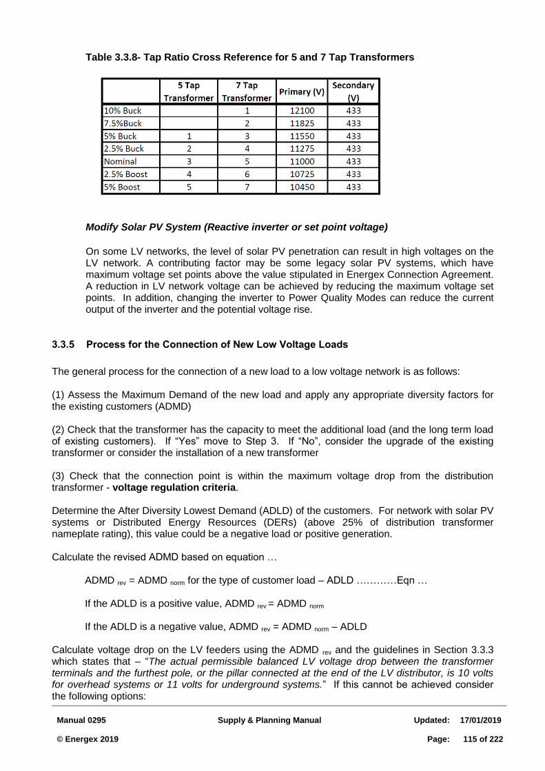
Manual 0295
Supply & Planning Manual
Updated:
17/01/2019 © Energex 2019
Page:
115 of 222
Table 3.3.8- Tap Ratio Cross Reference for 5 and 7 Tap Transformers
Modify Solar PV System (Reactive inverter or set point voltage)
On some LV networks, the level of solar PV penetration can result in high voltages on the LV network. A contributing factor may be some legacy solar PV systems, which have maximum voltage set points above the value stipulated in Energex Connection Agreement. A reduction in LV network voltage can be achieved by reducing the maximum voltage set points. In addition, changing the inverter to Power Quality Modes can reduce the current output of the inverter and the potential voltage rise.
3.3.5 Process for the Connection of New Low Voltage Loads
The general process for the connection of a new load to a low voltage network is as follows: (1) Assess the Maximum Demand of the new load and apply any appropriate diversity factors for the existing customers (ADMD) (2) Check that the transformer has the capacity to meet the additional load (and the long term load of existing customers). If “Yes” move to Step 3. If “No”, consider the upgrade of the existing transformer or consider the installation of a new transformer (3) Check that the connection point is within the maximum voltage drop from the distribution transformer - voltage regulation criteria. Determine the After Diversity Lowest Demand (ADLD) of the customers. For network with solar PV systems or Distributed Energy Resources (DERs) (above 25% of distribution transformer nameplate rating), this value could be a negative load or positive generation. Calculate the revised ADMD based on equation …
ADMD rev = ADMD norm for the type of customer load – ADLD …………Eqn …
If the ADLD is a positive value, ADMD rev = ADMD norm If the ADLD is a negative value, ADMD rev = ADMD norm – ADLD
Calculate voltage drop on the LV feeders using the ADMD rev and the guidelines in Section 3.3.3 which states that – “The actual permissible balanced LV voltage drop between the transformer terminals and the furthest pole, or the pillar connected at the end of the LV distributor, is 10 volts for overhead systems or 11 volts for underground systems.” If this cannot be achieved consider the following options:
Manual 0295
Supply & Planning Manual
Updated:
17/01/2019 © Energex 2019
Page:
116 of 222
a) Reconductor sections of the LV feeder b) Installation of a new transformer
(4) Check that the connection point is within the maximum length from the distribution transformer – protection criteria. Refer to Table 3.7.2 and 3.7.3 for the maximum protective length from the transformer for various LV conductors. If the connection point is beyond the maximum length, consider the following options:
a) Implement dual fuse arrangement at the transformer b) Reconductor sections of the LV feeder c) Installation of a new transformer
(5) Calculate the fault loop impedance between the customer premise and the distribution transformer – fault loop impedance criteria. If the fault loop impedance is below one ohm, no further action is required. If the fault loop impedance is above one ohm, consider the following options:
a) Replace the customer service fuse with a smaller size. A 50 A fuse will allow a fault loop impedance of 1.5 ohms, whilst a 32 A fuse will allow a fault loop impedance up to 2 ohms(the 32 A fuse should only be used for street light circuits). Ensure the fuse is above the maximum loading of the customer
b) Consider LV supply from an alternative location with a lower fault loop impedance c) Reconductor sections of the LV feeder and/or neutral d) Installation of a new transformer
Fault Loop Impedance and Protective Length can be calculated using a calculator, which is available at (Add Link Here)
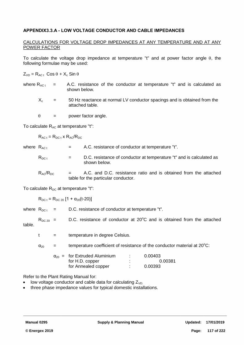
Manual 0295
Supply & Planning Manual
Updated:
17/01/2019 © Energex 2019
Page:
117 of 222
APPENDIX3.3.A - LOW VOLTAGE CONDUCTOR AND CABLE IMPEDANCES
CALCULATIONS FOR VOLTAGE DROP IMPEDANCES AT ANY TEMPERATURE AND AT ANY POWER FACTOR
To calculate the voltage drop impedance at temperature "t" and at power factor angle , the following formulae may be used:
ZVD = RAC t Cos + Xc Sin where RAC t = A.C. resistance of the conductor at temperature "t" and is calculated as
shown below.
Xc = 50 Hz reactance at normal LV conductor spacings and is obtained from the attached table.
= power factor angle. To calculate RAC at temperature "t": RAC t = RDC t x RAC/RDC where RAC t = A.C. resistance of conductor at temperature "t". RDC t = D.C. resistance of conductor at temperature "t" and is calculated as
shown below.
RAC/RDC = A.C. and D.C. resistance ratio and is obtained from the attached table for the particular conductor.
To calculate RDC at temperature "t": RDC t = RDC 20 [1 + α20(t-20)] where RDC t = D.C. resistance of conductor at temperature "t". RDC 20 = D.C. resistance of conductor at 20oC and is obtained from the attached table. t = temperature in degree Celsius. α20 = temperature coefficient of resistance of the conductor material at 20oC: α20 = for Extruded Aluminium : 0.00403 for H.D. copper : 0.00381 for Annealed copper : 0.00393 Refer to the Plant Rating Manual for:
low voltage conductor and cable data for calculating ZVD.
three phase impedance values for typical domestic installations.
Manual 0295
Supply & Planning Manual
Updated:
17/01/2019 © Energex 2019
Page:
118 of 222
3.4 GUIDELINES FOR SIZING OF DISTRIBUTION TRANSFORMERS
3.4.1 General Design Principles
Before any supply option can be considered, it is first necessary to examine the size and nature of the load. These two aspects affect not only the method of supply chosen but also the possible tariff options as well as any capital contributions payments by the customer. Refer to Section 3.2.3 for further information. There are 3 categories of C&I customers as follows: (1) CBD (3 feeder mesh arrangement – refer Figure 3.4.1) (2) C&I Urban (loop in and out – refer Figure 3.4.2) (3) C&I Remote or Rural (single tee – refer Figure 3.4.3)
Available Range of Transformers 3.4.1.1
The Energex building blocks range of transformers available for C&I customers are: (1) 500 kV.A – padmounted and dry type (2) 750 kV.A - padmounted, dry and ground type (3) 1000 kV.A - padmounted, dry and ground type (4) 1500 kV.A – dry type
Energex will only supply and maintain this range of transformers. The padmount and ground type transformers are mineral oil based.
Planning Process 3.4.1.2
In the planning process, the required number of external Low Voltage (LV) circuits will be determined by Energex. This can have an impact on the size and number of transformers at a C&I site.
For C&I customer categories (1) and (2), allowance should be made for a single LV tie supplying a minimum of 200 kVA of load and for 2 or more transformers to be installed at the substation if the customer load plus LV tie load exceeds 1000 kVA (Standard Network Building Block requirement). There is an exception for C&I Rural customers, where a LV tie is generally not required.
An LV tie serves 2 purposes; (1) for limited back-up supply in the case of loss of a transformer and/or (2) to facilitate CMEN earthing.
All substation enclosure designs should allow for an upgrade to the next transformer size, for example if the initial design was for a 750 kVA transformer, the substation enclosure design and the customers LV switchboard fault level should be based on a 1000 kVA transformer.
Where the customer load is likely to significantly increase over time, allowance should be made for the installation of 1500 kVA transformers (Substation enclosure and fault level for the customer’s LV switchboard). The fault current rating of LV switchboards should be based on Table 3.7.1 – Revised Impedances and Maximum Fault Levels.
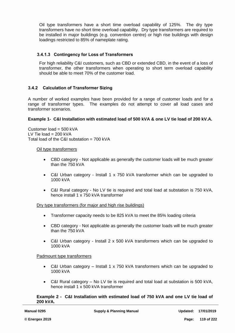
Manual 0295
Supply & Planning Manual
Updated:
17/01/2019 © Energex 2019
Page:
119 of 222
Oil type transformers have a short time overload capability of 125%. The dry type transformers have no short time overload capability. Dry type transformers are required to be installed in major buildings (e.g. convention centre) or high rise buildings with design loadings restricted to 85% of nameplate rating.
Contingency for Loss of Transformers 3.4.1.3
For high reliability C&I customers, such as CBD or extended CBD, in the event of a loss of transformer, the other transformers when operating to short term overload capability should be able to meet 70% of the customer load.
3.4.2 Calculation of Transformer Sizing
A number of worked examples have been provided for a range of customer loads and for a range of transformer types. The examples do not attempt to cover all load cases and transformer scenarios.
Example 1- C&I Installation with estimated load of 500 kVA & one LV tie load of 200 kV.A.
Customer load = 500 kVA LV Tie load = 200 kVA Total load of the C&I substation = 700 kVA
Oil type transformers
CBD category - Not applicable as generally the customer loads will be much greater than the 750 kVA
C&I Urban category - Install 1 x 750 kVA transformer which can be upgraded to 1000 kVA
C&I Rural category - No LV tie is required and total load at substation is 750 kVA, hence install 1 x 750 kVA transformer
Dry type transformers (for major and high rise buildings)
Transformer capacity needs to be 825 kVA to meet the 85% loading criteria
CBD category - Not applicable as generally the customer loads will be much greater than the 750 kVA
C&I Urban category - Install 2 x 500 kVA transformers which can be upgraded to 1000 kVA
Padmount type transformers
C&I Urban category – Install 1 x 750 kVA transformers which can be upgraded to 1000 kVA
C&I Rural category – No LV tie is required and total load at substation is 500 kVA, hence install 1 x 500 kVA transformer
Example 2 - C&I Installation with estimated load of 750 kVA and one LV tie load of 200 kVA.
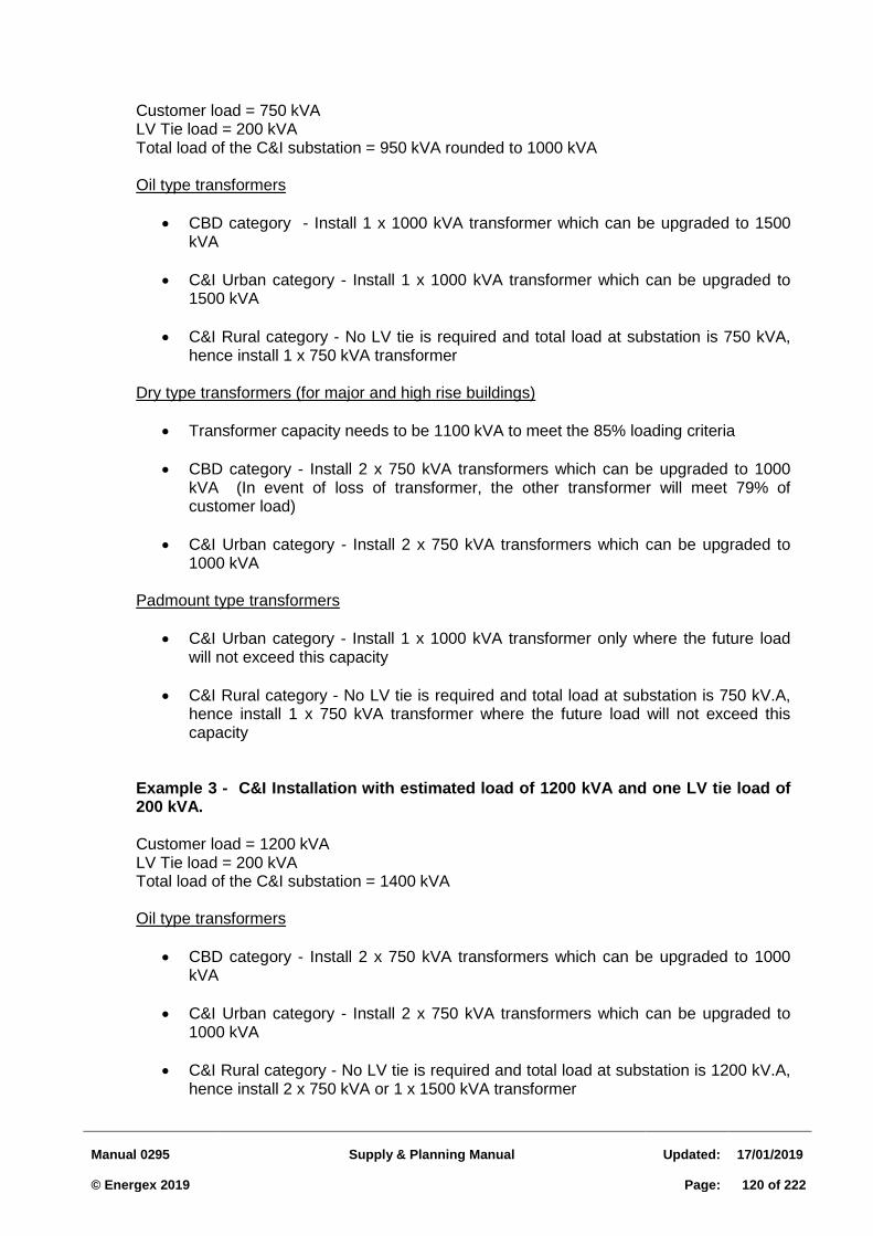
Manual 0295
Supply & Planning Manual
Updated:
17/01/2019 © Energex 2019
Page:
120 of 222
Customer load = 750 kVA LV Tie load = 200 kVA Total load of the C&I substation = 950 kVA rounded to 1000 kVA Oil type transformers
CBD category - Install 1 x 1000 kVA transformer which can be upgraded to 1500 kVA
C&I Urban category - Install 1 x 1000 kVA transformer which can be upgraded to 1500 kVA
C&I Rural category - No LV tie is required and total load at substation is 750 kVA, hence install 1 x 750 kVA transformer
Dry type transformers (for major and high rise buildings)
Transformer capacity needs to be 1100 kVA to meet the 85% loading criteria
CBD category - Install 2 x 750 kVA transformers which can be upgraded to 1000 kVA (In event of loss of transformer, the other transformer will meet 79% of customer load)
C&I Urban category - Install 2 x 750 kVA transformers which can be upgraded to 1000 kVA
Padmount type transformers
C&I Urban category - Install 1 x 1000 kVA transformer only where the future load will not exceed this capacity
C&I Rural category - No LV tie is required and total load at substation is 750 kV.A, hence install 1 x 750 kVA transformer where the future load will not exceed this capacity
Example 3 - C&I Installation with estimated load of 1200 kVA and one LV tie load of 200 kVA.
Customer load = 1200 kVA LV Tie load = 200 kVA Total load of the C&I substation = 1400 kVA Oil type transformers
CBD category - Install 2 x 750 kVA transformers which can be upgraded to 1000 kVA
C&I Urban category - Install 2 x 750 kVA transformers which can be upgraded to 1000 kVA
C&I Rural category - No LV tie is required and total load at substation is 1200 kV.A, hence install 2 x 750 kVA or 1 x 1500 kVA transformer
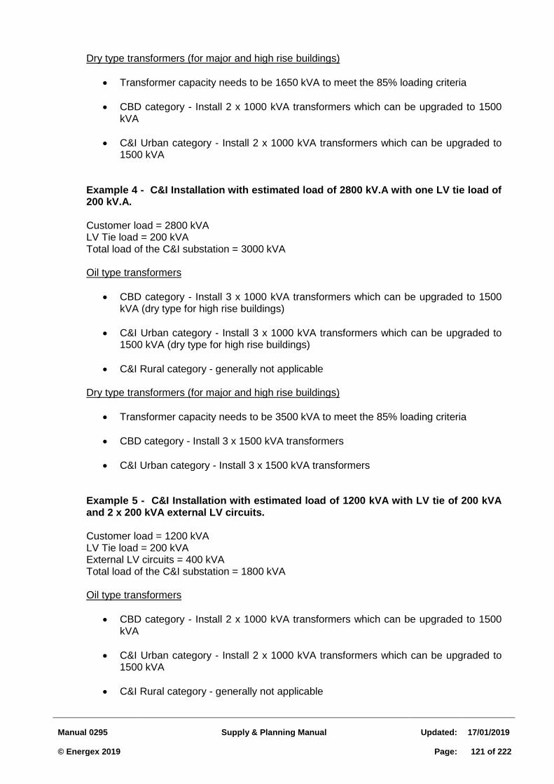
Manual 0295
Supply & Planning Manual
Updated:
17/01/2019 © Energex 2019
Page:
121 of 222
Dry type transformers (for major and high rise buildings)
Transformer capacity needs to be 1650 kVA to meet the 85% loading criteria
CBD category - Install 2 x 1000 kVA transformers which can be upgraded to 1500 kVA
C&I Urban category - Install 2 x 1000 kVA transformers which can be upgraded to 1500 kVA
Example 4 - C&I Installation with estimated load of 2800 kV.A with one LV tie load of 200 kV.A.
Customer load = 2800 kVA LV Tie load = 200 kVA Total load of the C&I substation = 3000 kVA Oil type transformers
CBD category - Install 3 x 1000 kVA transformers which can be upgraded to 1500 kVA (dry type for high rise buildings)
C&I Urban category - Install 3 x 1000 kVA transformers which can be upgraded to 1500 kVA (dry type for high rise buildings)
C&I Rural category - generally not applicable
Dry type transformers (for major and high rise buildings)
Transformer capacity needs to be 3500 kVA to meet the 85% loading criteria
CBD category - Install 3 x 1500 kVA transformers
C&I Urban category - Install 3 x 1500 kVA transformers Example 5 - C&I Installation with estimated load of 1200 kVA with LV tie of 200 kVA and 2 x 200 kVA external LV circuits.
Customer load = 1200 kVA LV Tie load = 200 kVA External LV circuits = 400 kVA Total load of the C&I substation = 1800 kVA Oil type transformers
CBD category - Install 2 x 1000 kVA transformers which can be upgraded to 1500 kVA
C&I Urban category - Install 2 x 1000 kVA transformers which can be upgraded to 1500 kVA
C&I Rural category - generally not applicable
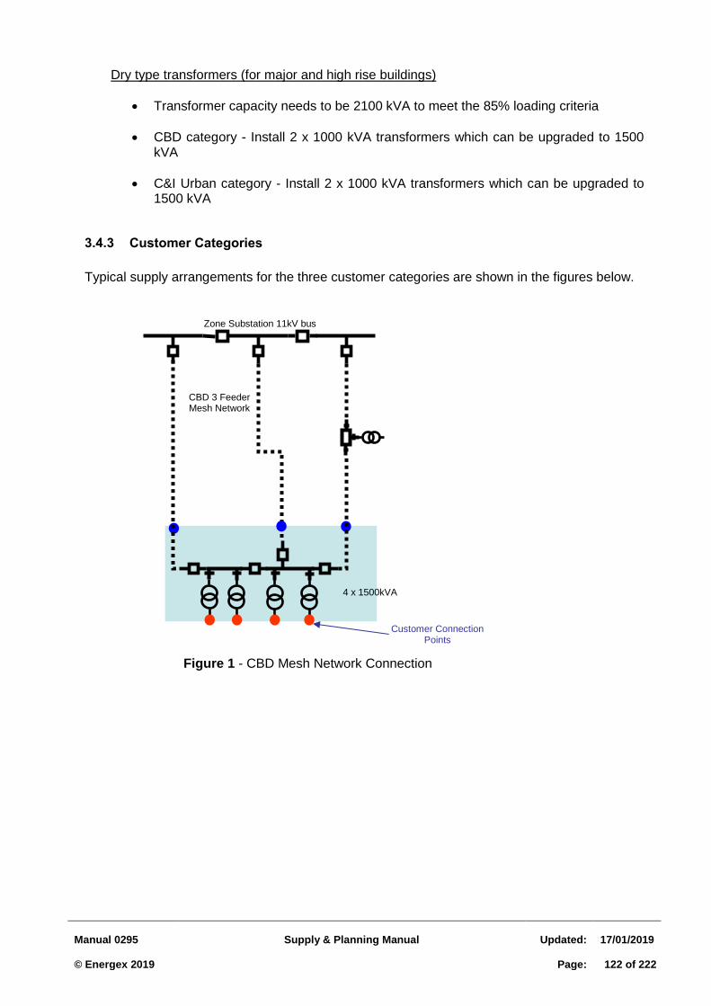
Manual 0295
Supply & Planning Manual
Updated:
17/01/2019 © Energex 2019
Page:
122 of 222
Dry type transformers (for major and high rise buildings)
Transformer capacity needs to be 2100 kVA to meet the 85% loading criteria
CBD category - Install 2 x 1000 kVA transformers which can be upgraded to 1500 kVA
C&I Urban category - Install 2 x 1000 kVA transformers which can be upgraded to 1500 kVA
3.4.3 Customer Categories
Typical supply arrangements for the three customer categories are shown in the figures below.
Zone Substation 11kV bus
CBD 3 Feeder Mesh Network
Customer Connection Points
Figure 1 - CBD Mesh Network Connection
4 x 1500kVA
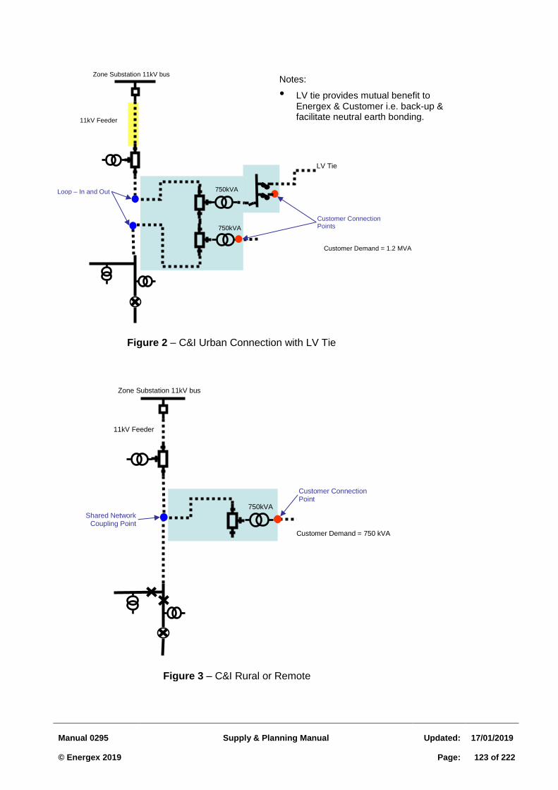
Manual 0295
Supply & Planning Manual
Updated:
17/01/2019 © Energex 2019
Page:
123 of 222
Zone Substation 11kV bus
11kV Feeder
750kVA
Customer Connection Points
Loop – In and Out
Figure 2 – C&I Urban Connection with LV Tie
750kVA
LV Tie
Customer Demand = 1.2 MVA
Notes:
• LV tie provides mutual benefit to Energex & Customer i.e. back-up & facilitate neutral earth bonding.
Zone Substation 11kV bus
11kV Feeder
750kVA
Customer Connection Point
Shared Network Coupling Point
Figure 3 – C&I Rural or Remote
Customer Demand = 750 kVA

Manual 0295
Supply & Planning Manual
Updated:
17/01/2019 © Energex 2019
Page:
124 of 222
3.5 LOW VOLTAGE TIE POLICY FOR SUBDIVISIONS
3.5.1 Introduction
Low voltage ties between adjacent distribution transformers improve network reliability and operational flexibility, as well as facilitating the use of CMEN earthing at transformers.
Ties should be established where practicable, subject to both:
economic feasibility, and
technical feasibility. Criteria for economic and technical feasibility are outlined below.
Ideally, in an urban network, each LV distributor circuit emanating from a transformer should tie to a similar circuit from an adjacent transformer. Of course, this will not always be practicable due to factors such as lot layout, road geometry and proximity of external circuits. However, reasonable efforts should be made to ensure that each urban transformer has at least one tie to adjacent LV areas
Figure 3.5.1 - An Example of an Ideal Urban LV Schematic With All LV Circuits Tied to Adjacent Areas
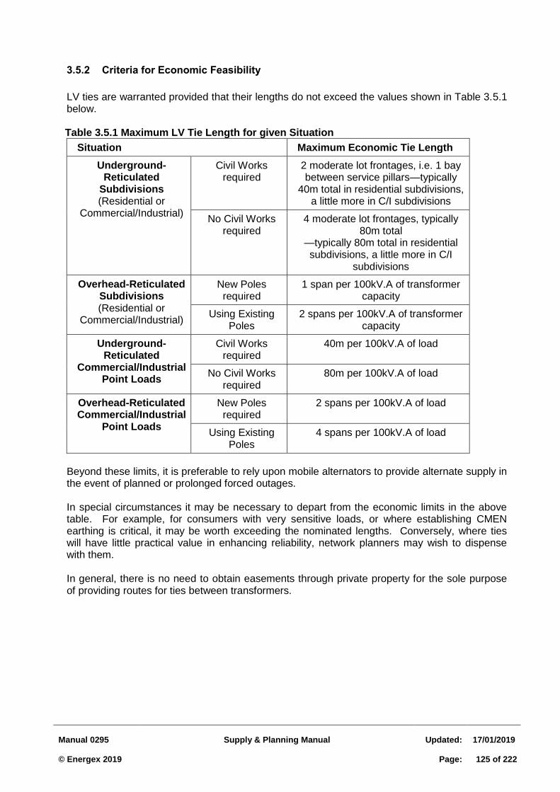
Manual 0295
Supply & Planning Manual
Updated:
17/01/2019 © Energex 2019
Page:
125 of 222
3.5.2 Criteria for Economic Feasibility
LV ties are warranted provided that their lengths do not exceed the values shown in Table 3.5.1 below.
Table 3.5.1 Maximum LV Tie Length for given Situation
Situation Maximum Economic Tie Length
Underground-Reticulated
Subdivisions (Residential or
Commercial/Industrial)
Civil Works required
2 moderate lot frontages, i.e. 1 bay between service pillars—typically
40m total in residential subdivisions, a little more in C/I subdivisions
No Civil Works required
4 moderate lot frontages, typically 80m total
—typically 80m total in residential subdivisions, a little more in C/I
subdivisions
Overhead-Reticulated Subdivisions (Residential or
Commercial/Industrial)
New Poles required
1 span per 100kV.A of transformer capacity
Using Existing Poles
2 spans per 100kV.A of transformer capacity
Underground-Reticulated
Commercial/Industrial Point Loads
Civil Works required
40m per 100kV.A of load
No Civil Works required
80m per 100kV.A of load
Overhead-Reticulated Commercial/Industrial
Point Loads
New Poles required
2 spans per 100kV.A of load
Using Existing Poles
4 spans per 100kV.A of load
Beyond these limits, it is preferable to rely upon mobile alternators to provide alternate supply in the event of planned or prolonged forced outages. In special circumstances it may be necessary to depart from the economic limits in the above table. For example, for consumers with very sensitive loads, or where establishing CMEN earthing is critical, it may be worth exceeding the nominated lengths. Conversely, where ties will have little practical value in enhancing reliability, network planners may wish to dispense with them. In general, there is no need to obtain easements through private property for the sole purpose of providing routes for ties between transformers.
Manual 0295
Supply & Planning Manual
Updated:
17/01/2019 © Energex 2019
Page:
126 of 222
3.5.3 Criteria for Technical Feasibility
To be technically feasible, the tie circuit should be able to carry the resulting load (when closed in) without exceeding:
voltage drop limits, or
cable/conductor current-carrying capacity. In general, ties between widely-spaced transformers in rural areas will not meet these criteria. Electrical calculations should be performed using average loads rather than peak loads. For subdivision developments, average loads may be assumed to be 50% of design ADMD/SD values. Other situations should be assessed on a case-by-case basis. For large point loads, it is recognized that ties may still be of value even if unable to support average loads. Consumers may be able to limit their loads to the capacity of the LV tie circuit for short periods and would prefer this to a total loss of supply. Ties to ‘independent’ transformers are preferable to ties to transformers fed from the same segment of 11kV mains between isolation points, since local 11kV problems or transformer problems will likely affect both LV areas.
Manual 0295
Supply & Planning Manual
Updated:
17/01/2019 © Energex 2019
Page:
127 of 222
3.6 LOW VOLTAGE SERVICES
3.6.1 General
Before a method of supply can be determined, several factors need to be considered, viz:
(a) What will the actual maximum demand be now and in the future as seen by the
system?
(b) Will this additional load cause an overload on the area transformer?
(c) Will the new load cause the voltage to drop below the minimum allowable either at the new load or elsewhere?
(d) Will the nature of the new load affect other customers in terms of fluctuations in
voltage, harmonics etc?
(e) Studies have shown that an LV network designed for a voltage drop using an ADMD of 4.5 kVA per customer can handle a voltage rise and solar PV load of 3 kVA per customer (assuming an ADLD of 0.5 kVA). It is expected that this will also apply to networks designed with an ADMD of 4.0 kVA.
Each of these questions is examined in more detail in the following sections.
3.6.2 Maximum Demand
(a) The actual maximum demand may be much less than the total connected load due to the
effect of diversity. The expenditure on services, mains and transformers may be far higher than necessary if no attempt is made to determine the actual diversified value, eg a small factory may have the following load characteristics:
Connected load 200 kW Load after diversity (AS/NZS 3000 maximum demand) 140 kW Estimated maximum load at any one time 50 kW
The system will only see the 50 kW load and hence the service, mains and transformer need be designed for only this load. (b) To be able to assess the maximum load on the low voltage system, considerable experience
is needed in this type of work, together with knowledge of the cycle of operation of the equipment. Often, a discussion with a representative of the organisation concerned will reveal how much equipment will be used at any one time and occasionally an indication of actual load can be obtained by checking the load at a similar sized and type of installation elsewhere.
(c) While each application must be considered individually, Tables 3.6.1 and 3.6.2 give some
typical After Diversity Maximum Demands. It should be noted that the After Diversity
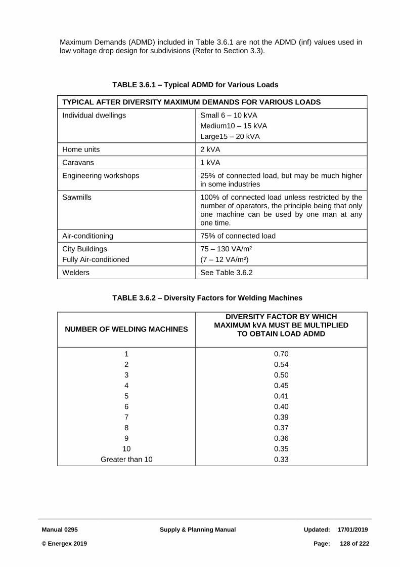
Manual 0295
Supply & Planning Manual
Updated:
17/01/2019 © Energex 2019
Page:
128 of 222
Maximum Demands (ADMD) included in Table 3.6.1 are not the ADMD (inf) values used in low voltage drop design for subdivisions (Refer to Section 3.3).
TABLE 3.6.1 – Typical ADMD for Various Loads
TABLE 3.6.2 – Diversity Factors for Welding Machines
TYPICAL AFTER DIVERSITY MAXIMUM DEMANDS FOR VARIOUS LOADS
Individual dwellings Small 6 – 10 kVA
Medium10 – 15 kVA
Large15 – 20 kVA
Home units 2 kVA
Caravans 1 kVA
Engineering workshops 25% of connected load, but may be much higher in some industries
Sawmills 100% of connected load unless restricted by the number of operators, the principle being that only one machine can be used by one man at any one time.
Air-conditioning 75% of connected load
City Buildings
Fully Air-conditioned
75 – 130 VA/m²
(7 – 12 VA/m²)
Welders See Table 3.6.2
NUMBER OF WELDING MACHINES
DIVERSITY FACTOR BY WHICH MAXIMUM kVA MUST BE MULTIPLIED
TO OBTAIN LOAD ADMD
1
2
3
4
5
6
7
8
9
10
Greater than 10
0.70
0.54
0.50
0.45
0.41
0.40
0.39
0.37
0.36
0.35
0.33
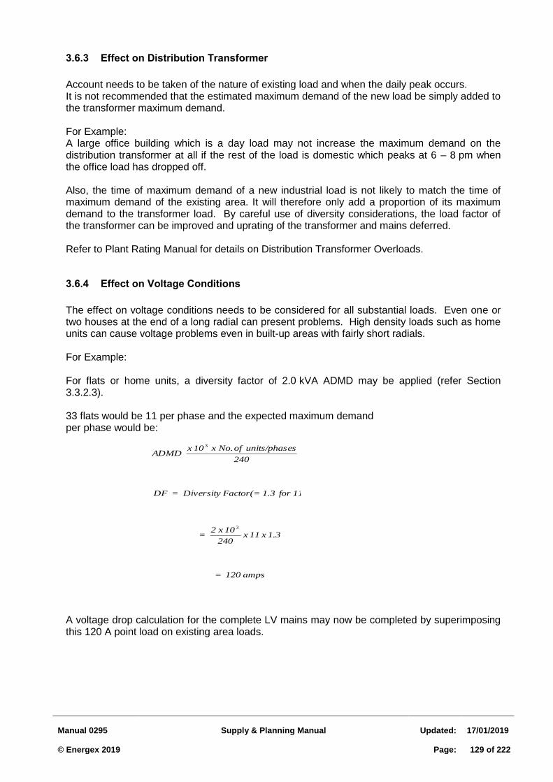
Manual 0295
Supply & Planning Manual
Updated:
17/01/2019 © Energex 2019
Page:
129 of 222
amps 120 =
1.3 x 11 x 240
10 x 2 =
units) 11 for 1.3Factor(=Diversity = DF
DF x 240
esunits/phas of No. x 10 x ADMD
3
3
3.6.3 Effect on Distribution Transformer
Account needs to be taken of the nature of existing load and when the daily peak occurs. It is not recommended that the estimated maximum demand of the new load be simply added to the transformer maximum demand.
For Example: A large office building which is a day load may not increase the maximum demand on the distribution transformer at all if the rest of the load is domestic which peaks at 6 – 8 pm when the office load has dropped off.
Also, the time of maximum demand of a new industrial load is not likely to match the time of maximum demand of the existing area. It will therefore only add a proportion of its maximum demand to the transformer load. By careful use of diversity considerations, the load factor of the transformer can be improved and uprating of the transformer and mains deferred.
Refer to Plant Rating Manual for details on Distribution Transformer Overloads.
3.6.4 Effect on Voltage Conditions
The effect on voltage conditions needs to be considered for all substantial loads. Even one or two houses at the end of a long radial can present problems. High density loads such as home units can cause voltage problems even in built-up areas with fairly short radials.
For Example:
For flats or home units, a diversity factor of 2.0 kVA ADMD may be applied (refer Section 3.3.2.3). 33 flats would be 11 per phase and the expected maximum demand per phase would be:
A voltage drop calculation for the complete LV mains may now be completed by superimposing this 120 A point load on existing area loads.
Manual 0295
Supply & Planning Manual
Updated:
17/01/2019 © Energex 2019
Page:
130 of 222
3.6.5 Solar PV and Batteries
In the case where a developer has requested parameters to facilitate or enable solar PV and
battery storage, the following requirements will apply (excluding bulk metered networks):
a. Solar PV grid connected inverter maximum export rating: of up to 5 kVA with Power
Quality Modes enabled on a single phase inverter, or 15 kVA with Power Quality
Modes enabled on a three phase inverter.
b. Combined solar PV and battery power rating: Where solar PV and batteries are DC
coupled to a single inverter the inverter rating is the power rating. For AC coupled
inverters, the power ratings of each of the inverters are summed to determine the
total power rating of the embedded generating system.
c. ADMD to remain at 4.0 kVA, Maximum balanced Voltage drop = 11 V (at any pillar
on the main cable run) but transformer tap setting should be chosen to achieve no
load voltage at transformer terminals in range 233 V to 243 V
d. The meter/switchboard wiring should also allow for appropriate metering
connections (refer to the Queensland Electricity Connections and Queensland
Electrical Metering Manuals (QECM and QEMM)
e. The size of the consumer’s mains be chosen to limit voltage rise from the
customer’s solar PV grid connected inverter to the point of common coupling (LV
pillar) to less than 2% of nominal voltage (230V/400V)
There should also be consideration for load control/demand management and potential tariff
changes and the customer loads should be configured/wired for the following scenarios:
Demand response enabled (DRED) control of battery storage equipment
Demand response enabled (DRED) control of air-conditioning units. (PeakSmart air-
conditioners)
Connection of pools, hot water systems and selected appliances to an economy
controlled tariff.
Applications for lower cost residential developments 3.6.5.1
The current ADMD for retirement homes, unit developments and town houses is 3 kVA per
customer. For applications which mandate solar PV and batteries on each or majority of
homes/units, the ADMD will remain at 3 kVA per customer.
Applications for solar PV and battery storage 3.6.5.2
Applications for solar PV and battery storage at each residential lot will still need to be progressed via the Energex Portal.
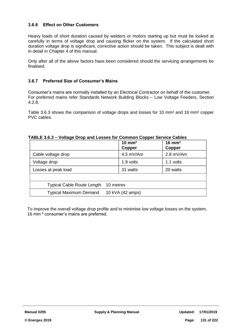
Manual 0295
Supply & Planning Manual
Updated:
17/01/2019 © Energex 2019
Page:
131 of 222
3.6.6 Effect on Other Customers
Heavy loads of short duration caused by welders or motors starting up but must be looked at carefully in terms of voltage drop and causing flicker on the system. If the calculated short duration voltage drop is significant, corrective action should be taken. This subject is dealt with in detail in Chapter 4 of this manual.
Only after all of the above factors have been considered should the servicing arrangements be finalised.
3.6.7 Preferred Size of Consumer’s Mains
Consumer’s mains are normally installed by an Electrical Contractor on behalf of the customer. For preferred mains refer Standards Network Building Blocks – Low Voltage Feeders, Section 4.2.8.
Table 3.6.3 shows the comparison of voltage drops and losses for 10 mm² and 16 mm² copper PVC cables.
TABLE 3.6.3 – Voltage Drop and Losses for Common Copper Service Cables
10 mm² Copper
16 mm² Copper
Cable voltage drop 4.5 mV/Am 2.8 mV/Am
Voltage drop 1.9 volts 1.1 volts
Losses at peak load 31 watts 20 watts
Typical Cable Route Length 10 metres
Typical Maximum Demand 10 kVA (42 amps)
To improve the overall voltage drop profile and to minimise low voltage losses on the system, 16 mm ² consumer’s mains are preferred.
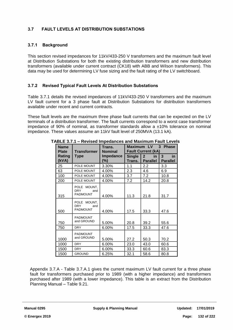
Manual 0295
Supply & Planning Manual
Updated:
17/01/2019 © Energex 2019
Page:
132 of 222
3.7 FAULT LEVELS AT DISTRIBUTION SUBSTATIONS
3.7.1 Background
This section revised impedances for 11kV/433-250 V transformers and the maximum fault level at Distribution Substations for both the existing distribution transformers and new distribution transformers (available under current contract (CK18) with ABB and Wilson transformers). This data may be used for determining LV fuse sizing and the fault rating of the LV switchboard.
3.7.2 Revised Typical Fault Levels At Distribution Substations
Table 3.7.1 details the revised impedances of 11kV/433-250 V transformers and the maximum LV fault current for a 3 phase fault at Distribution Substations for distribution transformers available under recent and current contracts.
These fault levels are the maximum three phase fault currents that can be expected on the LV terminals of a distribution transformer. The fault currents correspond to a worst case transformer impedance of 90% of nominal, as transformer standards allow a ±10% tolerance on nominal impedance. These values assume an 11kV fault level of 250MVA (13.1 kA).
TABLE 3.7.1 – Revised Impedances and Maximum Fault Levels
Name Plate Rating (kVA)
Transformer Type
Trans. Nominal Impedance (%)
Maximum LV 3 Phase Fault Current (kA)
Single Trans.
2 in Parallel
3 in Parallel
25 POLE MOUNT 3.30% 1.1 2.2 3.3
63 POLE MOUNT 4.00% 2.3 4.6 6.9
100 POLE MOUNT 4.00% 3.7 7.2 10.8
200 POLE MOUNT 4.00% 7.2 14.2 20.8
315
POLE MOUNT, DRY and PADMOUNT
4.00% 11.3 21.8 31.7
500
POLE MOUNT, DRY and PADMOUNT
4.00% 17.5 33.3 47.6
750
PADMOUNT and GROUND
5.00% 20.8 39.2 55.6
750 DRY 6.00% 17.5 33.3 47.6
1000
PADMOUNT and GROUND
5.00% 27.2 50.3 70.2
1000 DRY 6.00% 23.0 43.0 60.6
1500 DRY 6.00% 33.3 60.6 83.3
1500 GROUND 6.25% 32.1 58.6 80.8
Appendix 3.7.A - Table 3.7.A.1 gives the current maximum LV fault current for a three phase fault for transformers purchased prior to 1989 (with a higher impedance) and transformers purchased after 1989 (with a lower impedance). This table is an extract from the Distribution Planning Manual – Table 9.21.
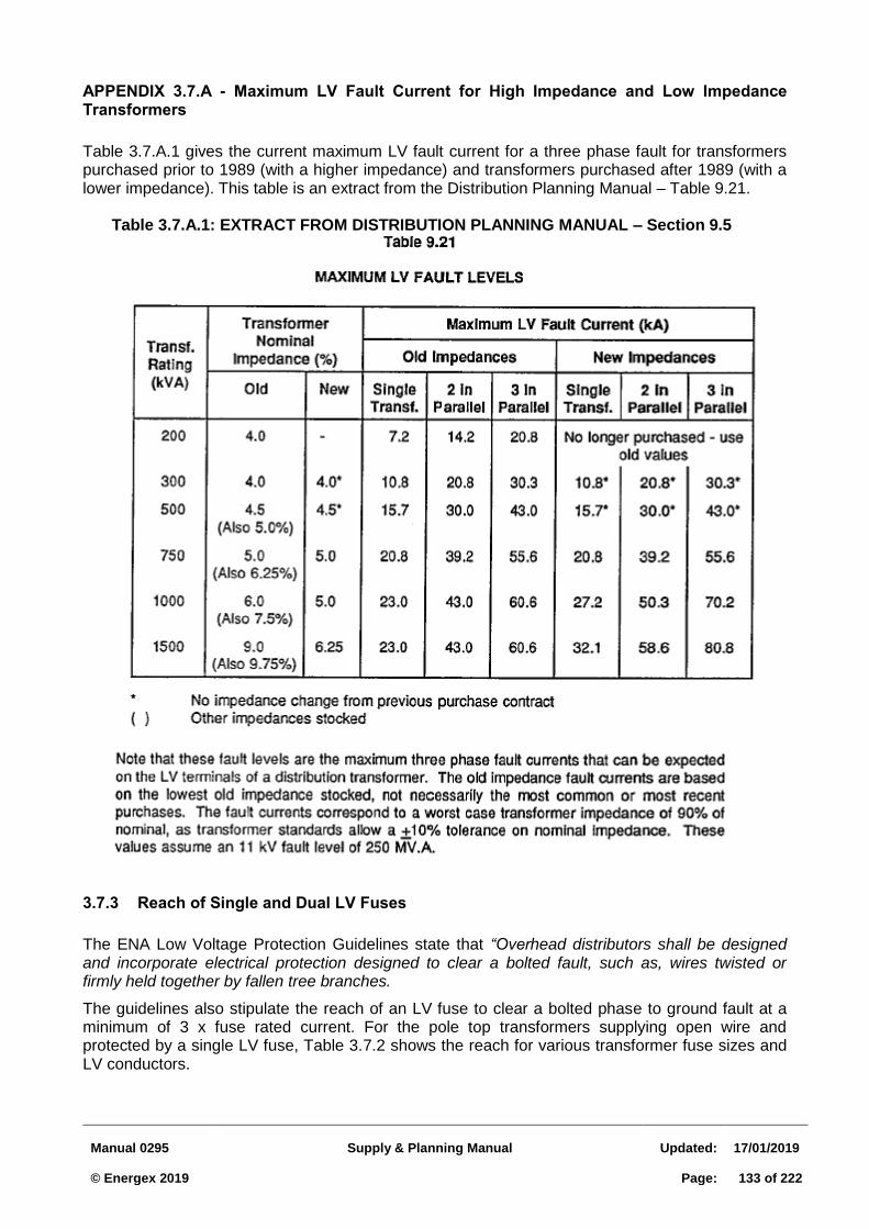
Manual 0295
Supply & Planning Manual
Updated:
17/01/2019 © Energex 2019
Page:
133 of 222
APPENDIX 3.7.A - Maximum LV Fault Current for High Impedance and Low Impedance Transformers
Table 3.7.A.1 gives the current maximum LV fault current for a three phase fault for transformers purchased prior to 1989 (with a higher impedance) and transformers purchased after 1989 (with a lower impedance). This table is an extract from the Distribution Planning Manual – Table 9.21.
Table 3.7.A.1: EXTRACT FROM DISTRIBUTION PLANNING MANUAL – Section 9.5
3.7.3 Reach of Single and Dual LV Fuses
The ENA Low Voltage Protection Guidelines state that “Overhead distributors shall be designed and incorporate electrical protection designed to clear a bolted fault, such as, wires twisted or firmly held together by fallen tree branches.
The guidelines also stipulate the reach of an LV fuse to clear a bolted phase to ground fault at a minimum of 3 x fuse rated current. For the pole top transformers supplying open wire and protected by a single LV fuse, Table 3.7.2 shows the reach for various transformer fuse sizes and LV conductors.
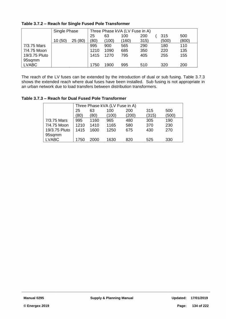
Manual 0295
Supply & Planning Manual
Updated:
17/01/2019 © Energex 2019
Page:
134 of 222
Table 3.7.2 – Reach for Single Fused Pole Transformer
Single Phase Three Phase kVA (LV Fuse in A)
10 (50) 25 (80) 25 (80)
63 (100)
100 (160)
200 ( 315)
315 (500)
500 (800)
7/3.75 Mars 995 900 565 290 180 110 7/4.75 Moon 1210 1090 685 350 220 135 19/3.75 Pluto 1415 1270 795 405 255 155 95sqmm LVABC 1750 1900 995 510 320 200
The reach of the LV fuses can be extended by the introduction of dual or sub fusing. Table 3.7.3 shows the extended reach where dual fuses have been installed. Sub fusing is not appropriate in an urban network due to load transfers between distribution transformers.
Table 3.7.3 – Reach for Dual Fused Pole Transformer
Three Phase kVA (LV Fuse in A)
25 (80)
63 (80)
100 (100)
200 (200)
315 (315)
500 (500)
7/3.75 Mars 995 1160 965 480 305 190 7/4.75 Moon 1210 1410 1165 580 370 230 19/3.75 Pluto 1415 1600 1250 675 430 270 95sqmm LVABC 1750 2000 1630 820 525 330
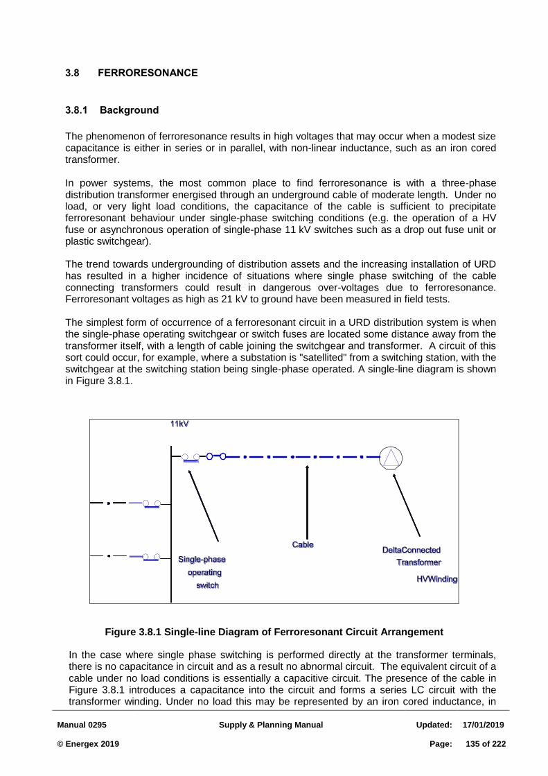
Manual 0295
Supply & Planning Manual
Updated:
17/01/2019 © Energex 2019
Page:
135 of 222
3.8 FERRORESONANCE
3.8.1 Background
The phenomenon of ferroresonance results in high voltages that may occur when a modest size capacitance is either in series or in parallel, with non-linear inductance, such as an iron cored transformer.
In power systems, the most common place to find ferroresonance is with a three-phase distribution transformer energised through an underground cable of moderate length. Under no load, or very light load conditions, the capacitance of the cable is sufficient to precipitate ferroresonant behaviour under single-phase switching conditions (e.g. the operation of a HV fuse or asynchronous operation of single-phase 11 kV switches such as a drop out fuse unit or plastic switchgear).
The trend towards undergrounding of distribution assets and the increasing installation of URD has resulted in a higher incidence of situations where single phase switching of the cable connecting transformers could result in dangerous over-voltages due to ferroresonance. Ferroresonant voltages as high as 21 kV to ground have been measured in field tests.
The simplest form of occurrence of a ferroresonant circuit in a URD distribution system is when the single-phase operating switchgear or switch fuses are located some distance away from the transformer itself, with a length of cable joining the switchgear and transformer. A circuit of this sort could occur, for example, where a substation is "satellited" from a switching station, with the switchgear at the switching station being single-phase operated. A single-line diagram is shown in Figure 3.8.1.
Figure 3.8.1 Single-line Diagram of Ferroresonant Circuit Arrangement
In the case where single phase switching is performed directly at the transformer terminals, there is no capacitance in circuit and as a result no abnormal circuit. The equivalent circuit of a cable under no load conditions is essentially a capacitive circuit. The presence of the cable in Figure 3.8.1 introduces a capacitance into the circuit and forms a series LC circuit with the transformer winding. Under no load this may be represented by an iron cored inductance, in
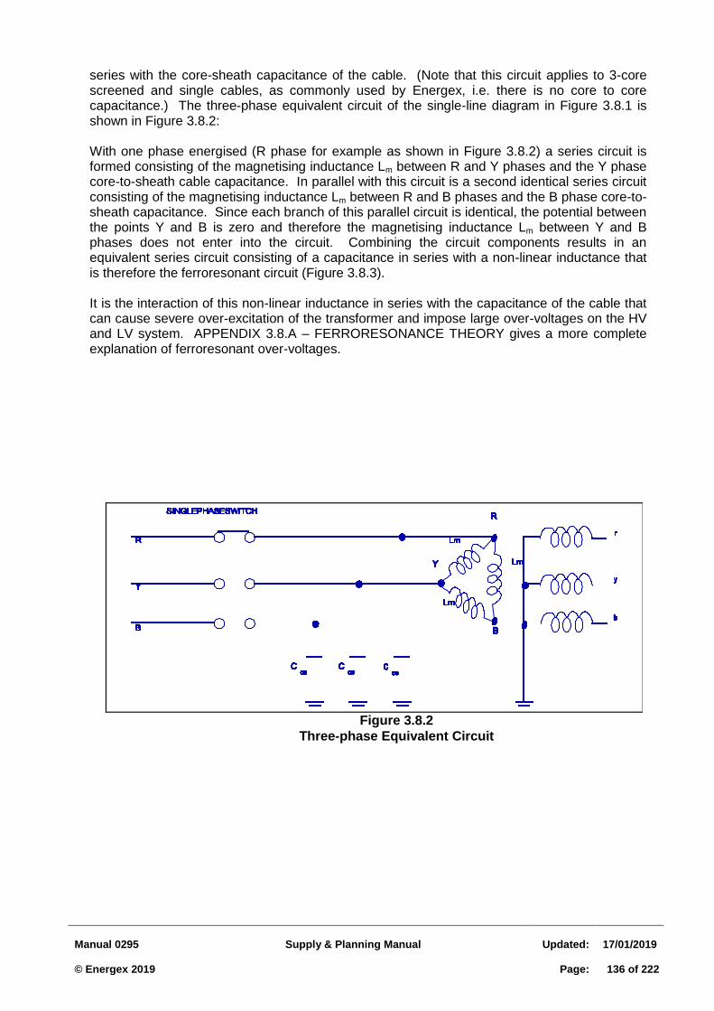
Manual 0295
Supply & Planning Manual
Updated:
17/01/2019 © Energex 2019
Page:
136 of 222
Figure 3.8.2
Three-phase Equivalent Circuit
series with the core-sheath capacitance of the cable. (Note that this circuit applies to 3-core screened and single cables, as commonly used by Energex, i.e. there is no core to core capacitance.) The three-phase equivalent circuit of the single-line diagram in Figure 3.8.1 is shown in Figure 3.8.2:
With one phase energised (R phase for example as shown in Figure 3.8.2) a series circuit is formed consisting of the magnetising inductance Lm between R and Y phases and the Y phase core-to-sheath cable capacitance. In parallel with this circuit is a second identical series circuit consisting of the magnetising inductance Lm between R and B phases and the B phase core-to-sheath capacitance. Since each branch of this parallel circuit is identical, the potential between the points Y and B is zero and therefore the magnetising inductance Lm between Y and B phases does not enter into the circuit. Combining the circuit components results in an equivalent series circuit consisting of a capacitance in series with a non-linear inductance that is therefore the ferroresonant circuit (Figure 3.8.3).
It is the interaction of this non-linear inductance in series with the capacitance of the cable that can cause severe over-excitation of the transformer and impose large over-voltages on the HV and LV system. APPENDIX 3.8.A – FERRORESONANCE THEORY gives a more complete explanation of ferroresonant over-voltages.
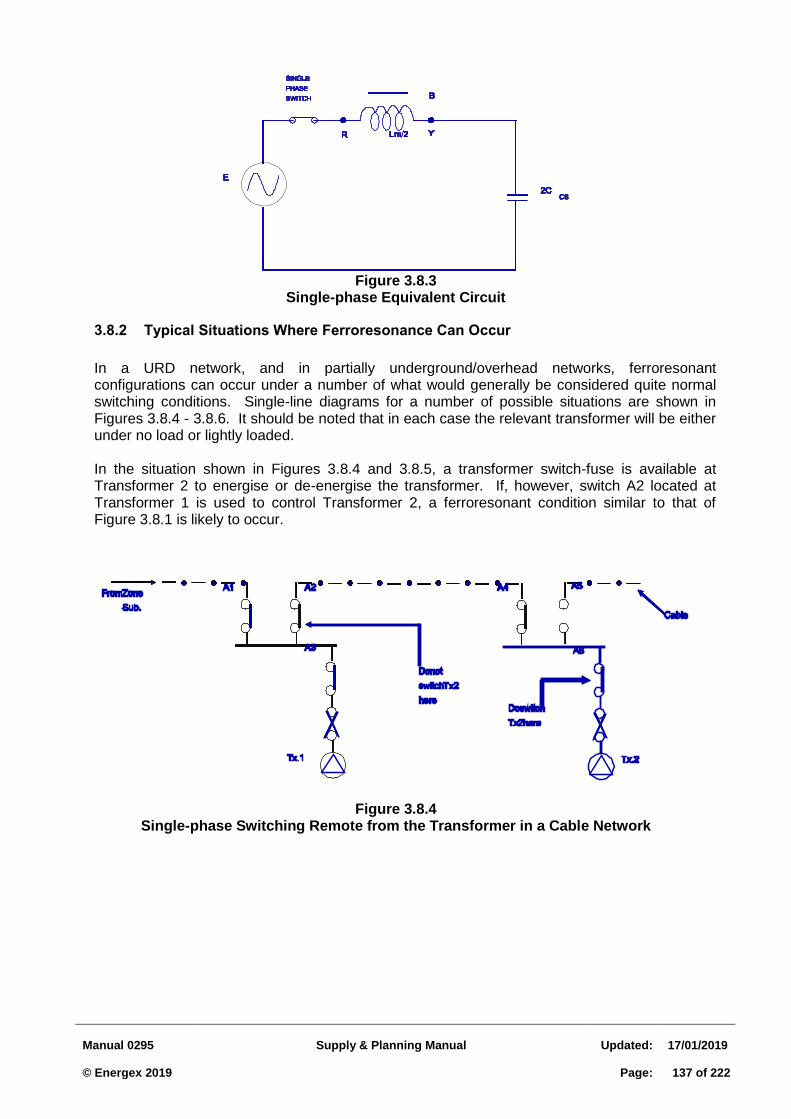
Manual 0295
Supply & Planning Manual
Updated:
17/01/2019 © Energex 2019
Page:
137 of 222
Figure 3.8.3
Single-phase Equivalent Circuit
3.8.2 Typical Situations Where Ferroresonance Can Occur
In a URD network, and in partially underground/overhead networks, ferroresonant configurations can occur under a number of what would generally be considered quite normal switching conditions. Single-line diagrams for a number of possible situations are shown in Figures 3.8.4 - 3.8.6. It should be noted that in each case the relevant transformer will be either under no load or lightly loaded.
In the situation shown in Figures 3.8.4 and 3.8.5, a transformer switch-fuse is available at Transformer 2 to energise or de-energise the transformer. If, however, switch A2 located at Transformer 1 is used to control Transformer 2, a ferroresonant condition similar to that of Figure 3.8.1 is likely to occur.
Figure 3.8.4 Single-phase Switching Remote from the Transformer in a Cable Network
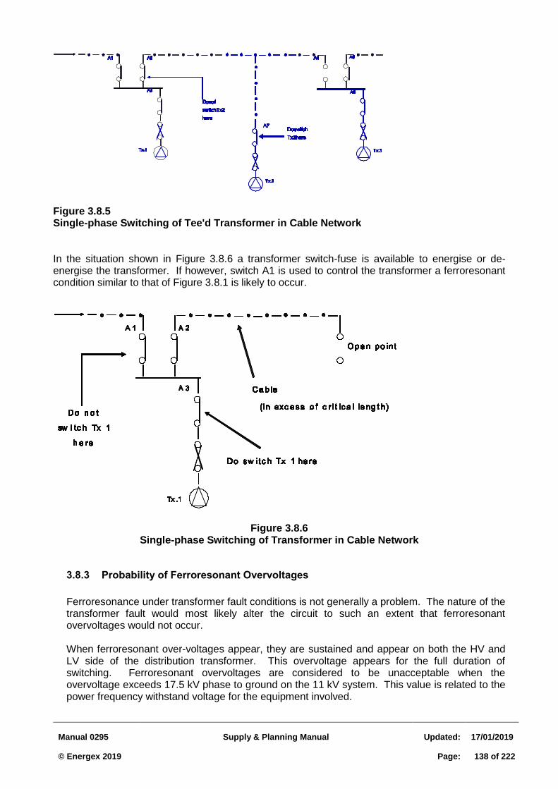
Manual 0295
Supply & Planning Manual
Updated:
17/01/2019 © Energex 2019
Page:
138 of 222
Figure 3.8.5 Single-phase Switching of Tee'd Transformer in Cable Network In the situation shown in Figure 3.8.6 a transformer switch-fuse is available to energise or de-energise the transformer. If however, switch A1 is used to control the transformer a ferroresonant condition similar to that of Figure 3.8.1 is likely to occur.
Figure 3.8.6
Single-phase Switching of Transformer in Cable Network
3.8.3 Probability of Ferroresonant Overvoltages
Ferroresonance under transformer fault conditions is not generally a problem. The nature of the transformer fault would most likely alter the circuit to such an extent that ferroresonant overvoltages would not occur.
When ferroresonant over-voltages appear, they are sustained and appear on both the HV and LV side of the distribution transformer. This overvoltage appears for the full duration of switching. Ferroresonant overvoltages are considered to be unacceptable when the overvoltage exceeds 17.5 kV phase to ground on the 11 kV system. This value is related to the power frequency withstand voltage for the equipment involved.
Manual 0295
Supply & Planning Manual
Updated:
17/01/2019 © Energex 2019
Page:
139 of 222
The particular circuit state is governed by the phase angle of the voltage under which switching is affected.
Probability of ferroresonant overvoltages occurring is greatest during de-energising of the transformer. Approximately 50% of de-energising switchings will result in ferroresonant voltages if the conditions for ferroresonance exist. The probability during energisation of the transformer is only 10% (reference 4).
Damage due to ferroresonant overvoltages would probably not result in immediate failure of relatively new installations. Ferroresonant overvoltages are more likely to cause accelerated deterioration of the insulation, resulting in shortening of the life of the installation. For example:
Initiation of partial discharge in cables, leading to eventual failure.
De-orientation of the grain-oriented silicon steel in transformers, leading to excessive losses, hence core heating and oil deterioration.
3.8.4 Methods of Controlling Ferroresonance
The four most effective methods of controlling ferroresonance are:
(a) three-phase switching; (b) single-phase switching at transformers; (c) resistive load on the transformers; and (d) limiting cable length.
Methods (a) and (d) require action on the part of the system designer. Methods (a) and (c) require special operating procedures to ensure that there is effectively no length of cable being energised or de-energised at the same time as the transformer, or the presence of some load.
(a) Three-phase Switching
If there is one aspect of ferroresonance that finds universal agreement in the literature as to a suitable method of controlling ferroresonance, it is that the use of ganged three-phase switching is an effective means of doing so.
Clearly, except in the transient periods during non-simultaneous operation of each individual phase, a ferroresonant circuit could not be formed. The major difficulty in applying three-phase switching equipment is mainly one of cost and in the case of underground systems; the physical size of the switchgear has been prohibitive. In recent times, however, compact extendible three-phase switchgear has appeared on the market at competitive prices and of a size that can be installed in padmounts.
Ganged 11 kV EDO fuse units have been purchased for the purpose of installation on transformers that are subject to ferroresonant over voltages. The transformer will then be three phase switched in the event of a single-phase fault. Note, however, that ganged dropouts can only be closed single phase, hence three phase switching devices such as air breaks need to be used for re-energisation.
Ganged 11 kV EDO fuse units may only be used on up to 300 kVA capacity transformers that are subject to ferroresonance. Transformers above 300 kV A capacity that are subject to ferroresonance should be fused at the HV terminals using an RMU.
(b) Single-phase Switching at the Transformer
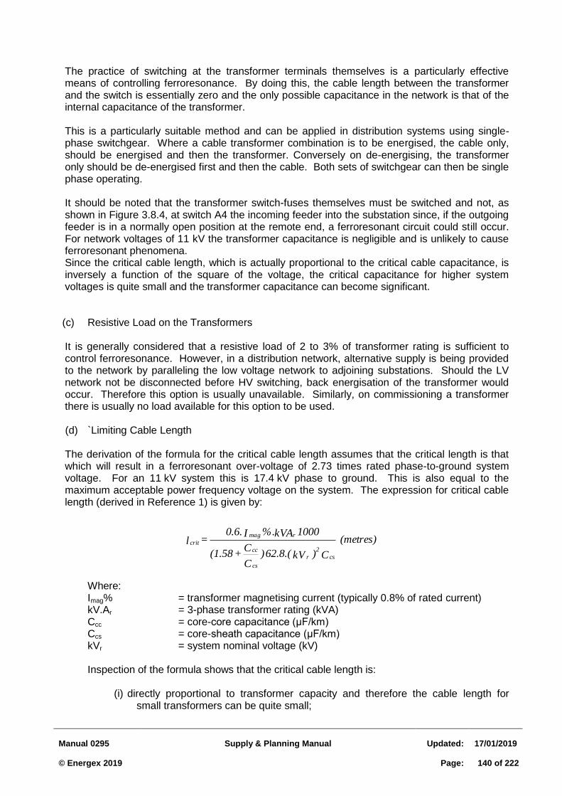
Manual 0295
Supply & Planning Manual
Updated:
17/01/2019 © Energex 2019
Page:
140 of 222
(metres)
C )kV62.8.( )C
C + (1.58
1000 kVA%. I 0.6. = l
cs
2
r
cs
cc
rmag
crit
The practice of switching at the transformer terminals themselves is a particularly effective means of controlling ferroresonance. By doing this, the cable length between the transformer and the switch is essentially zero and the only possible capacitance in the network is that of the internal capacitance of the transformer.
This is a particularly suitable method and can be applied in distribution systems using single-phase switchgear. Where a cable transformer combination is to be energised, the cable only, should be energised and then the transformer. Conversely on de-energising, the transformer only should be de-energised first and then the cable. Both sets of switchgear can then be single phase operating.
It should be noted that the transformer switch-fuses themselves must be switched and not, as shown in Figure 3.8.4, at switch A4 the incoming feeder into the substation since, if the outgoing feeder is in a normally open position at the remote end, a ferroresonant circuit could still occur. For network voltages of 11 kV the transformer capacitance is negligible and is unlikely to cause ferroresonant phenomena. Since the critical cable length, which is actually proportional to the critical cable capacitance, is inversely a function of the square of the voltage, the critical capacitance for higher system voltages is quite small and the transformer capacitance can become significant.
(c) Resistive Load on the Transformers
It is generally considered that a resistive load of 2 to 3% of transformer rating is sufficient to control ferroresonance. However, in a distribution network, alternative supply is being provided to the network by paralleling the low voltage network to adjoining substations. Should the LV network not be disconnected before HV switching, back energisation of the transformer would occur. Therefore this option is usually unavailable. Similarly, on commissioning a transformer there is usually no load available for this option to be used.
(d) `Limiting Cable Length
The derivation of the formula for the critical cable length assumes that the critical length is that which will result in a ferroresonant over-voltage of 2.73 times rated phase-to-ground system voltage. For an 11 kV system this is 17.4 kV phase to ground. This is also equal to the maximum acceptable power frequency voltage on the system. The expression for critical cable length (derived in Reference 1) is given by:
Where: Imag% = transformer magnetising current (typically 0.8% of rated current) kV.Ar = 3-phase transformer rating (kVA) Ccc = core-core capacitance (μF/km) Ccs = core-sheath capacitance (μF/km) kVr = system nominal voltage (kV) Inspection of the formula shows that the critical cable length is:
(i) directly proportional to transformer capacity and therefore the cable length for small transformers can be quite small;
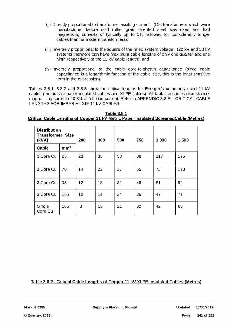
Manual 0295
Supply & Planning Manual
Updated:
17/01/2019 © Energex 2019
Page:
141 of 222
(ii) Directly proportional to transformer exciting current. (Old transformers which were manufactured before cold rolled grain oriented steel was used and had magnetising currents of typically up to 5%, allowed for considerably longer cables than for modern transformers);
(iii) Inversely proportional to the square of the rated system voltage. (22 kV and 33 kV
systems therefore can have maximum cable lengths of only one quarter and one ninth respectively of the 11 kV cable length); and
(iv) Inversely proportional to the cable core-to-sheath capacitance (since cable
capacitance is a logarithmic function of the cable size, this is the least sensitive term in the expression).
Tables 3.8.1, 3.8.2 and 3.8.3 show the critical lengths for Energex’s commonly used 11 kV cables (metric size paper insulated cables and XLPE cables). All tables assume a transformer magnetising current of 0.8% of full load current. Refer to APPENDIC 3.8.B – CRITICAL CABLE LENGTHS FOR IMPERIAL SIE 11 kV CABLES.
Table 3.8.1
Critical Cable Lengths of Copper 11 kV Metric Paper Insulated ScreenedCable (Metres)
Distribution Transformer Size (kVA)
200
300
500
750
1 000
1 500
Cable mm2
3 Core Cu
25 23 35 58 88 117 175
3 Core Cu
70 14 22 37 55 73 110
3 Core Cu 95 12 18 31 46 61 92
3 Core Cu 185 10 14 24 36 47 71
Single Core Cu
185 8 13 21 32 42 63
Table 3.8.2 - Critical Cable Lengths of Copper 11 kV XLPE Insulated Cables (Metres)
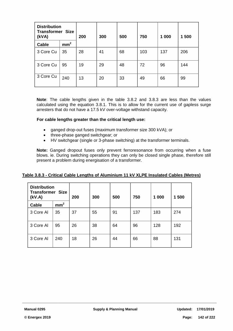
Manual 0295
Supply & Planning Manual
Updated:
17/01/2019 © Energex 2019
Page:
142 of 222
Distribution Transformer Size (kVA)
200
300
500
750
1 000
1 500
Cable mm2
3 Core Cu 35 28 41 68 103 137 206
3 Core Cu 95 19 29 48 72 96 144
3 Core Cu 240 13 20 33 49 66 99
Note: The cable lengths given in the table 3.8.2 and 3.8.3 are less than the values calculated using the equation 3.8.1. This is to allow for the current use of gapless surge arresters that do not have a 17.5 kV over-voltage withstand capacity.
For cable lengths greater than the critical length use:
ganged drop-out fuses (maximum transformer size 300 kVA); or
three-phase ganged switchgear; or
HV switchgear (single or 3-phase switching) at the transformer terminals.
Note: Ganged dropout fuses only prevent ferroresonance from occurring when a fuse blows. ie. During switching operations they can only be closed single phase, therefore still present a problem during energisation of a transformer.
Table 3.8.3 - Critical Cable Lengths of Aluminium 11 kV XLPE Insulated Cables (Metres)
Distribution Transformer Size (kV.A)
200
300
500
750
1 000
1 500
Cable mm2
3 Core Al 35 37 55 91 137 183 274
3 Core Al 95 26 38 64 96 128 192
3 Core Al 240 18 26 44 66 88 131
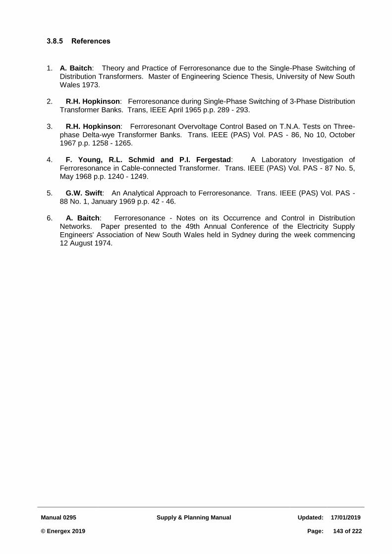
Manual 0295
Supply & Planning Manual
Updated:
17/01/2019 © Energex 2019
Page:
143 of 222
3.8.5 References
1. A. Baitch: Theory and Practice of Ferroresonance due to the Single-Phase Switching of Distribution Transformers. Master of Engineering Science Thesis, University of New South Wales 1973.
2. R.H. Hopkinson: Ferroresonance during Single-Phase Switching of 3-Phase Distribution
Transformer Banks. Trans, IEEE April 1965 p.p. 289 - 293. 3. R.H. Hopkinson: Ferroresonant Overvoltage Control Based on T.N.A. Tests on Three-
phase Delta-wye Transformer Banks. Trans. IEEE (PAS) Vol. PAS - 86, No 10, October 1967 p.p. 1258 - 1265.
4. F. Young, R.L. Schmid and P.I. Fergestad: A Laboratory Investigation of
Ferroresonance in Cable-connected Transformer. Trans. IEEE (PAS) Vol. PAS - 87 No. 5, May 1968 p.p. 1240 - 1249.
5. G.W. Swift: An Analytical Approach to Ferroresonance. Trans. IEEE (PAS) Vol. PAS -
88 No. 1, January 1969 p.p. 42 - 46. 6. A. Baitch: Ferroresonance - Notes on its Occurrence and Control in Distribution
Networks. Paper presented to the 49th Annual Conference of the Electricity Supply Engineers' Association of New South Wales held in Sydney during the week commencing 12 August 1974.
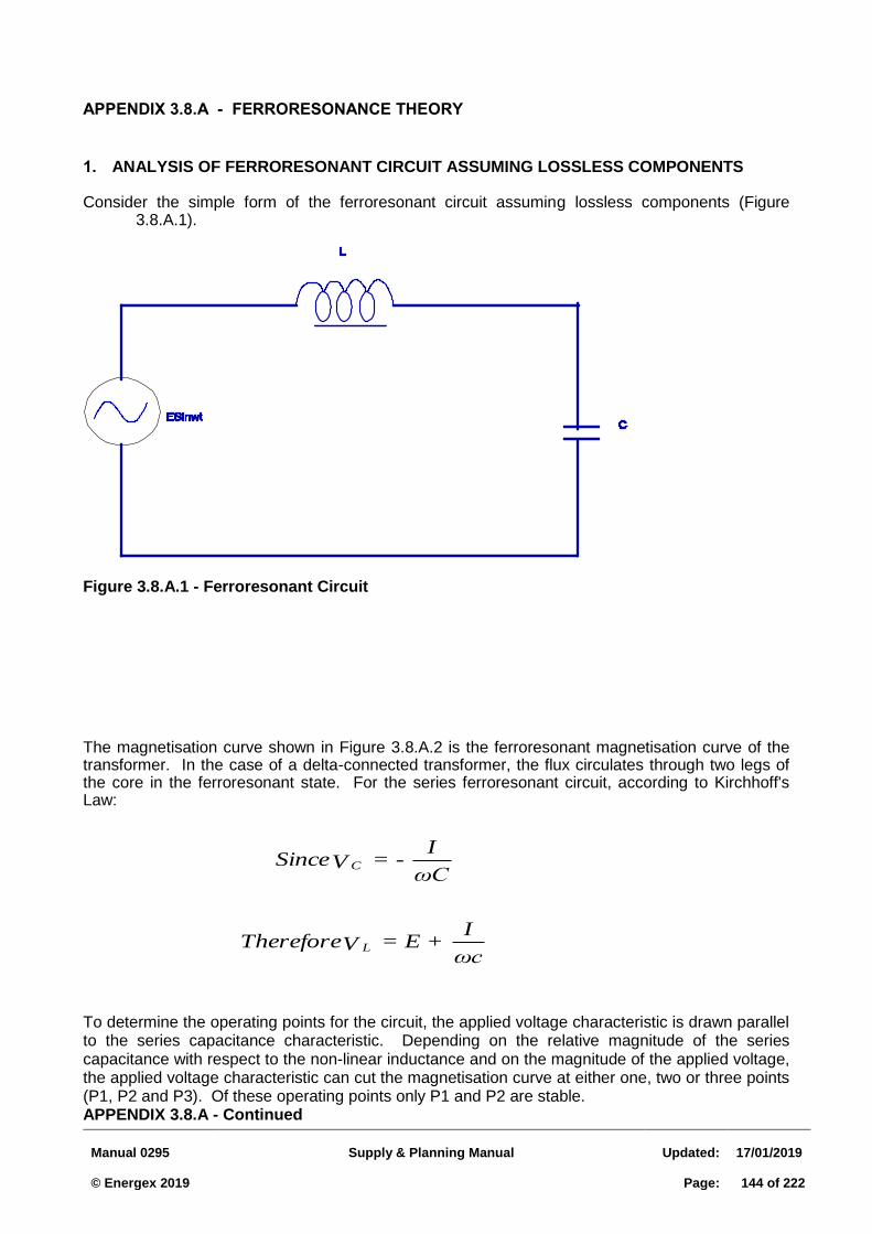
Manual 0295
Supply & Planning Manual
Updated:
17/01/2019 © Energex 2019
Page:
144 of 222
ωc
I = E + VTherefore
ωC
I = - VSince
L
C
APPENDIX 3.8.A - FERRORESONANCE THEORY
1. ANALYSIS OF FERRORESONANT CIRCUIT ASSUMING LOSSLESS COMPONENTS Consider the simple form of the ferroresonant circuit assuming lossless components (Figure
3.8.A.1).
Figure 3.8.A.1 - Ferroresonant Circuit
The magnetisation curve shown in Figure 3.8.A.2 is the ferroresonant magnetisation curve of the transformer. In the case of a delta-connected transformer, the flux circulates through two legs of the core in the ferroresonant state. For the series ferroresonant circuit, according to Kirchhoff's Law:
To determine the operating points for the circuit, the applied voltage characteristic is drawn parallel to the series capacitance characteristic. Depending on the relative magnitude of the series capacitance with respect to the non-linear inductance and on the magnitude of the applied voltage, the applied voltage characteristic can cut the magnetisation curve at either one, two or three points (P1, P2 and P3). Of these operating points only P1 and P2 are stable. APPENDIX 3.8.A - Continued
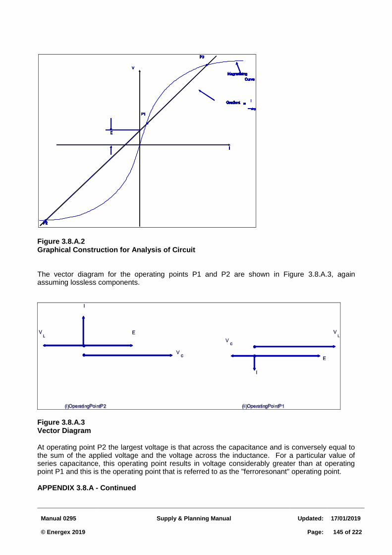
Manual 0295
Supply & Planning Manual
Updated:
17/01/2019 © Energex 2019
Page:
145 of 222
Figure 3.8.A.2 Graphical Construction for Analysis of Circuit The vector diagram for the operating points P1 and P2 are shown in Figure 3.8.A.3, again assuming lossless components.
Figure 3.8.A.3 Vector Diagram At operating point P2 the largest voltage is that across the capacitance and is conversely equal to the sum of the applied voltage and the voltage across the inductance. For a particular value of series capacitance, this operating point results in voltage considerably greater than at operating point P1 and this is the operating point that is referred to as the "ferroresonant" operating point. APPENDIX 3.8.A - Continued
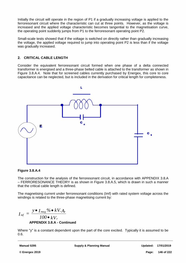
Manual 0295
Supply & Planning Manual
Updated:
17/01/2019 © Energex 2019
Page:
146 of 222
Initially the circuit will operate in the region of P1 if a gradually increasing voltage is applied to the ferroresonant circuit where the characteristic can cut at three points. However, as the voltage is increased and the applied voltage characteristic becomes tangential to the magnetisation curve, the operating point suddenly jumps from P1 to the ferroresonant operating point P2. Small-scale tests showed that if the voltage is switched on directly rather than gradually increasing the voltage, the applied voltage required to jump into operating point P2 is less than if the voltage was gradually increased. 2. CRITICAL CABLE LENGTH Consider the equivalent ferroresonant circuit formed when one phase of a delta connected transformer is energised and a three-phase belted cable is attached to the transformer as shown in Figure 3.8.A.4. Note that for screened cables currently purchased by Energex, this core to core capacitance can be neglected, but is included in the derivation for critical length for completeness.
Figure 3.8.A.4 The construction for the analysis of the ferroresonant circuit, in accordance with APPENDIX 3.8.A – FERRORESONANCE THEORY is as shown in Figure 3.8.A.5, which is drawn in such a manner that the critical cable length is defined. The magnetising current under ferroresonant conditions (Imf) with rated system voltage across the windings is related to the three-phase magnetising current by:
kV 100
AkV. % I y = I
r
rmag
mf
APPENDIX 3.8.A - Continued Where "y" is a constant dependent upon the part of the core excited. Typically it is assumed to be 0.6.
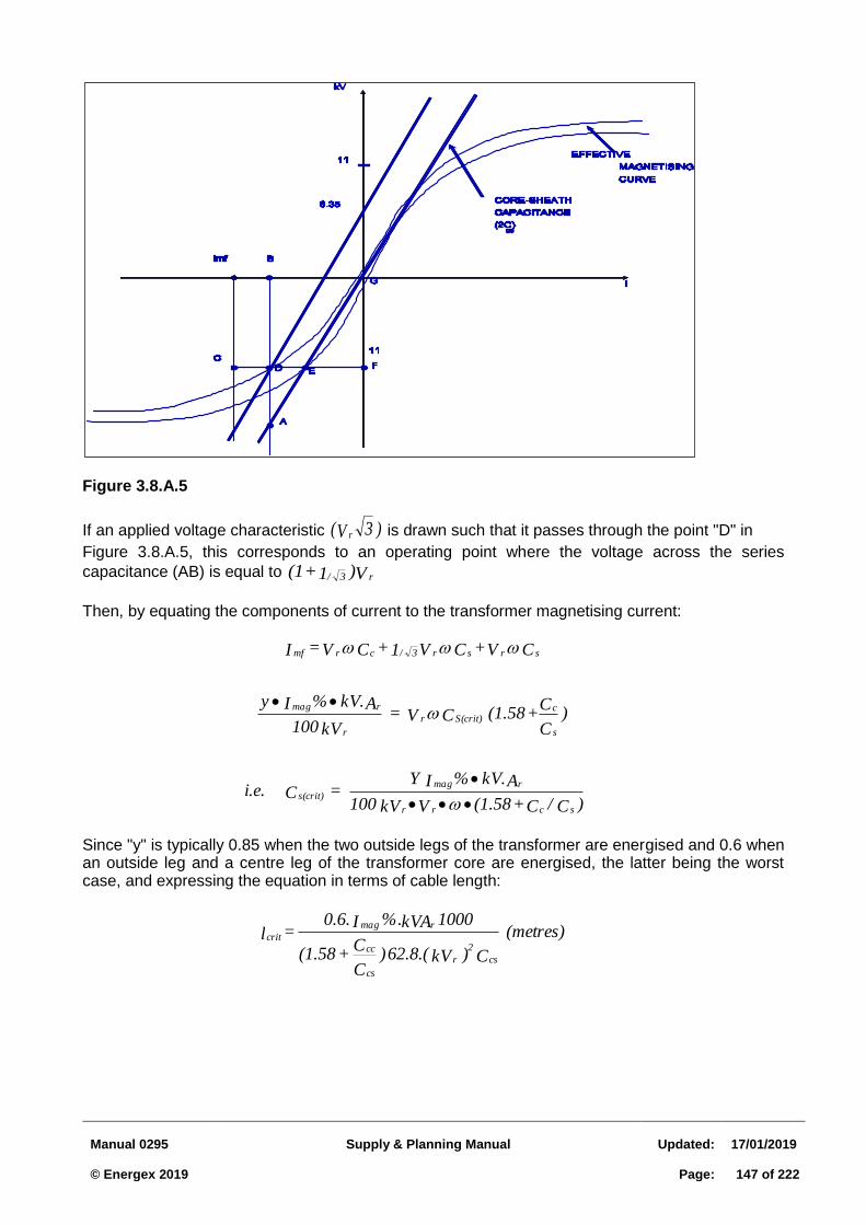
Manual 0295
Supply & Planning Manual
Updated:
17/01/2019 © Energex 2019
Page:
147 of 222
Figure 3.8.A.5
If an applied voltage characteristic )3V( r is drawn such that it passes through the point "D" in
Figure 3.8.A.5, this corresponds to an operating point where the voltage across the series
capacitance (AB) is equal to V)1 + (1 r3/
Then, by equating the components of current to the transformer magnetising current:
Since "y" is typically 0.85 when the two outside legs of the transformer are energised and 0.6 when an outside leg and a centre leg of the transformer core are energised, the latter being the worst case, and expressing the equation in terms of cable length:
)C/C+(1.58VkV 100
AkV.%I Y = C i.e.
)C
C+(1.58 CV =
kV100
AkV.%I y
CV + CV1 + CV = I
scrr
rmag
s(crit)
s
cS(crit)r
r
rmag
srsr3/crmf
(metres)
C )kV62.8.( )C
C + (1.58
1000 kVA%. I 0.6. = l
cs
2
r
cs
cc
rmag
crit
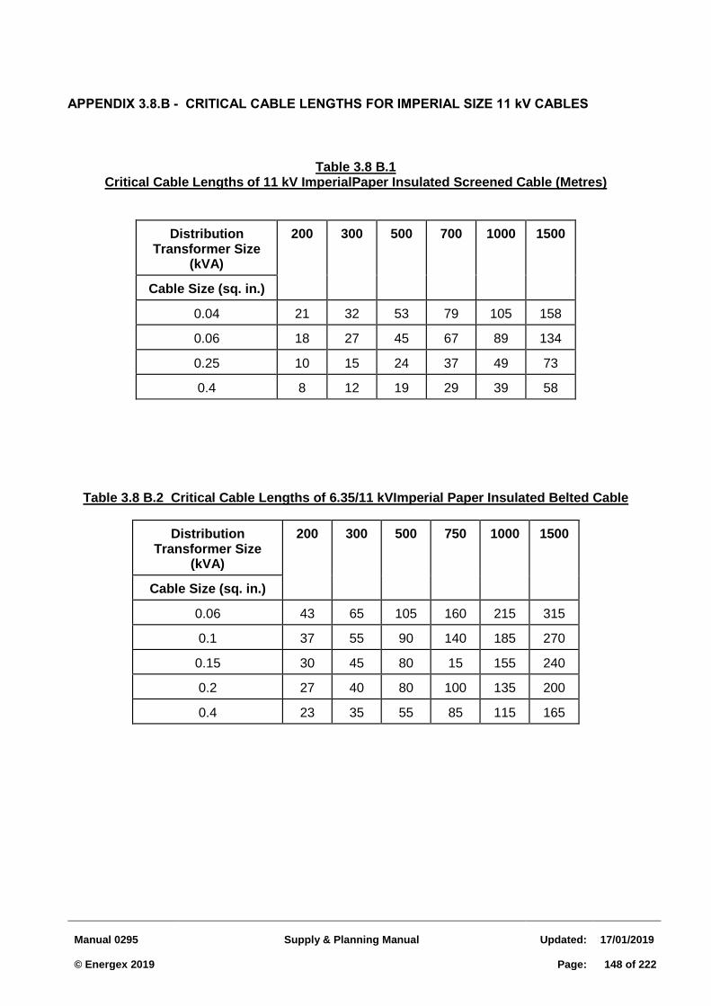
Manual 0295
Supply & Planning Manual
Updated:
17/01/2019 © Energex 2019
Page:
148 of 222
APPENDIX 3.8.B - CRITICAL CABLE LENGTHS FOR IMPERIAL SIZE 11 kV CABLES
Table 3.8 B.1
Critical Cable Lengths of 11 kV ImperialPaper Insulated Screened Cable (Metres)
Distribution Transformer Size
(kVA)
200 300 500 700 1000 1500
Cable Size (sq. in.)
0.04 21 32 53 79 105 158
0.06 18 27 45 67 89 134
0.25 10 15 24 37 49 73
0.4 8 12 19 29 39 58
Table 3.8 B.2 Critical Cable Lengths of 6.35/11 kVImperial Paper Insulated Belted Cable
Distribution Transformer Size
(kVA)
200 300 500 750 1000 1500
Cable Size (sq. in.)
0.06 43 65 105 160 215 315
0.1 37 55 90 140 185 270
0.15 30 45 80 15 155 240
0.2 27 40 80 100 135 200
0.4 23 35 55 85 115 165
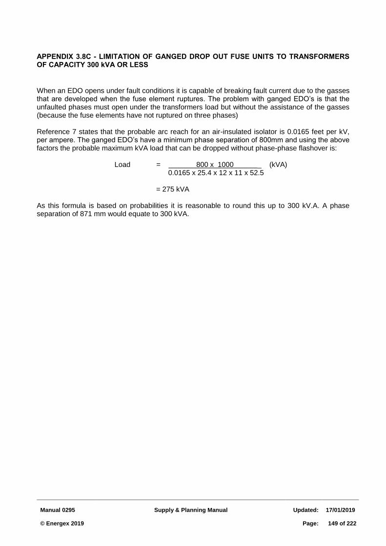
Manual 0295
Supply & Planning Manual
Updated:
17/01/2019 © Energex 2019
Page:
149 of 222
APPENDIX 3.8C - LIMITATION OF GANGED DROP OUT FUSE UNITS TO TRANSFORMERS OF CAPACITY 300 kVA OR LESS
When an EDO opens under fault conditions it is capable of breaking fault current due to the gasses that are developed when the fuse element ruptures. The problem with ganged EDO’s is that the unfaulted phases must open under the transformers load but without the assistance of the gasses (because the fuse elements have not ruptured on three phases) Reference 7 states that the probable arc reach for an air-insulated isolator is 0.0165 feet per kV, per ampere. The ganged EDO’s have a minimum phase separation of 800mm and using the above factors the probable maximum kVA load that can be dropped without phase-phase flashover is:
Load = 800 x 1000 _ (kVA) 0.0165 x 25.4 x 12 x 11 x 52.5 = 275 kVA As this formula is based on probabilities it is reasonable to round this up to 300 kV.A. A phase separation of 871 mm would equate to 300 kVA.
Manual 0295
Supply & Planning Manual
Updated:
17/01/2019 © Energex 2019
Page:
150 of 222
3.9 11 kV TIE POLICY FOR SUBDIVISIONS
3.9.1 Introduction
Energex has a responsibility to ensure network configurations resulting from new customer installations are designed to facilitate the safe and timely restoration of supply, including repairs to the network following a fault. This document outlines conceptual and practical information relating to the planning of the Energex HV1 network and applies to all new HV extensions covered under Subdivision Supply Agreements. Supply and planning arrangements for large installations and HV customers are covered separately under Section 3.2 of this manual.
The objective of this policy is to ensure extensions to the HV network are planned to ensure least whole of life costs (including maintenance and community costs) and facilitate application of Energex’s restoration of supply targets.
3.9.2 General Reliability Standard
The Energex general reliability standard is consistent with the ESAA document “Guideline for Reliability Assessment Planning - November 1997”. This allows for supply arrangements where full alternate supply to customer installations is not available. An example situation is on short and lightly loaded HV radial spurs that “tee-off” the HV feeder backbone. This arrangement is considered adequate provided that the method of supply chosen is practical and represents the least cost considering community, maintenance and operating costs.
Assessment of the adequacy of such arrangements requires evaluation of various parameters as detailed in Energex’s Reliability Assessment Planning guidelines. These include costs allocated to load at risk, energy at risk and the frequency and duration of outages. Such analysis enables an economic comparison between the annualised capital cost of network reinforcement and the associated marginal reduction in the community cost of unsupplied energy. In the case of underground feeders, economic justification has considered the cost of supplying materials (not installation), in accordance with subdivision policy.
In addition to the general reliability standard, Energex’s restoration of supply targets specify the maximum outage duration any customer will experience at one time.
3.9.3 Energex HV Feeder Tie Policy
Reliability Assessment Planning of HV extensions typically takes into consideration the following factors:
1. expected failure rate of installed plant and equipment including underground cables, joints and terminations as well as ring main units
2. potential outage duration of failed plant and equipment (e.g.: eight hour repair time for underground cable)
3. the nature of the load (commercial, industrial or residential)
4. expected network maintenance requirements
5. proximity of installed network to alternative feeders
1 References to "HV" apply to the 11 kV distribution system.
Manual 0295
Supply & Planning Manual
Updated:
17/01/2019 © Energex 2019
Page:
151 of 222
Standard planning requirements have been developed for various supply arrangements based on reliability assessments using nominal values for system parameters. These requirements are intended for guidance only as a general “rule of thumb” for what represents the most economical supply arrangement. Assessment of supply options for ties associated with HV extensions have been made, and form the basis of the loading and distance criteria for the installation of ties as shown in Tables 3.9.1 and 3.9.2. Further assessment of supply options by the local Asset Management representative may be warranted if site specific factors vary significantly from normally assumed values.
In this policy, the term “HV extension” includes all stages in a staged URD development.
The “ultimate load” is the product of the appropriate after diversity maximum demand (ADMD) multiplied by the number of lots involved in the stage.
This policy only applies to developments involving 2 or more transformers, and does not apply to individual small developments with loads less than 300 kVA, even if they exceed the criteria in Section 3.9.3.2 below by “adding on” to an existing larger development.
HV feeder extension with ultimate load less than 1.2 MVA 3.9.3.1
Where the ultimate load of a HV extension is less than 1.2 MVA, regardless of whether the network is overhead or underground, the most economical method of supply is typically via a single tee off from the existing HV reticulation. In this case, the practice of using mobile 1 MW, 11 kV diesel generator sets as standby sets to supply load during an outage should be considered.
HV feeder extension with ultimate load between 1.2 MVA and 3 MVA 3.9.3.2
An 11 kV tie will be required where the ultimate load of a new HV extension is between 1.2 MV.A and 3 MV.A, and the new transformer to be installed is 315 kVA or larger and the maximum length of 11 kV tie is not exceeded.
Tables 3.9.1 and 3.9.2 provide guidelines for determining the maximum length of OH & UG 11 kV tie, based on a 1 km route length of 11 kV spur extension. As an example, for an overhead route length of 11 kV extension of 2.0 km and a load of 1.2 MVA, the maximum length of 11 kV overhead tie would be 1.2 MVA x 2.0 = 2.4 km.
Where the existing load on the 11 kV spur is 1.2 MVA or greater, further clarification of the requirement for a tie is required and the local Asset Manager must be advised of the proposed extension in order to identify immediate and longer term planning requirements. In particular, the adequacy of the HV network to supply the extension within thermal limits and statutory voltage requirements should be addressed.
In these instances, a single tee off from the existing HV reticulation may not represent the most economic supply arrangement from a “whole of life” cost perspective. Guiding principles for supply arrangements for such extensions are detailed below:
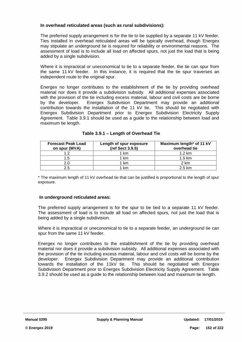
Manual 0295
Supply & Planning Manual
Updated:
17/01/2019 © Energex 2019
Page:
152 of 222
In overhead reticulated areas (such as rural subdivisions): The preferred supply arrangement is for the tie to be supplied by a separate 11 kV feeder. Ties installed in overhead reticulated areas will be typically overhead, though Energex may stipulate an underground tie is required for reliability or environmental reasons. The assessment of load is to include all load on affected spurs, not just the load that is being added by a single subdivision.
Where it is impractical or uneconomical to tie to a separate feeder, the tie can spur from the same 11 kV feeder. In this instance, it is required that the tie spur traverses an independent route to the original spur.
Energex no longer contributes to the establishment of the tie by providing overhead material nor does it provide a subdivision subsidy. All additional expenses associated with the provision of the tie including excess material, labour and civil costs are be borne by the developer. Energex Subdivision Department may provide an additional contribution towards the installation of the 11 kV tie. This should be negotiated with Energex Subdivision Department prior to Energex Subdivision Electricity Supply Agreement. Table 3.9.1 should be used as a guide to the relationship between load and maximum tie length.
Table 3.9.1 – Length of Overhead Tie
Forecast Peak Load
on spur (MVA) Length of spur exposure
(ref Sect 3.9.5) Maximum length* of 11 kV
overhead tie
1.2 1 km 1.2 km
1.5 1 km 1.5 km
2.0 1 km 2 km
2.5 1 km 2.5 km
* The maximum length of 11 kV overhead tie that can be justified is proportional to the length of spur exposure.
In underground reticulated areas: The preferred supply arrangement is for the spur to be tied to a separate 11 kV feeder. The assessment of load is to include all load on affected spurs, not just the load that is being added by a single subdivision. Where it is impractical or uneconomical to tie to a separate feeder, an underground tie can spur from the same 11 kV feeder. Energex no longer contributes to the establishment of the tie by providing overhead material nor does it provide a subdivision subsidy. All additional expenses associated with the provision of the tie including excess material, labour and civil costs will be borne by the developer. Energex Subdivision Department may provide an additional contribution towards the installation of the 11kV tie. This should be negotiated with Energex Subdivision Department prior to Energex Subdivision Electricity Supply Agreement. Table 3.9.2 should be used as a guide to the relationship between load and maximum tie length.
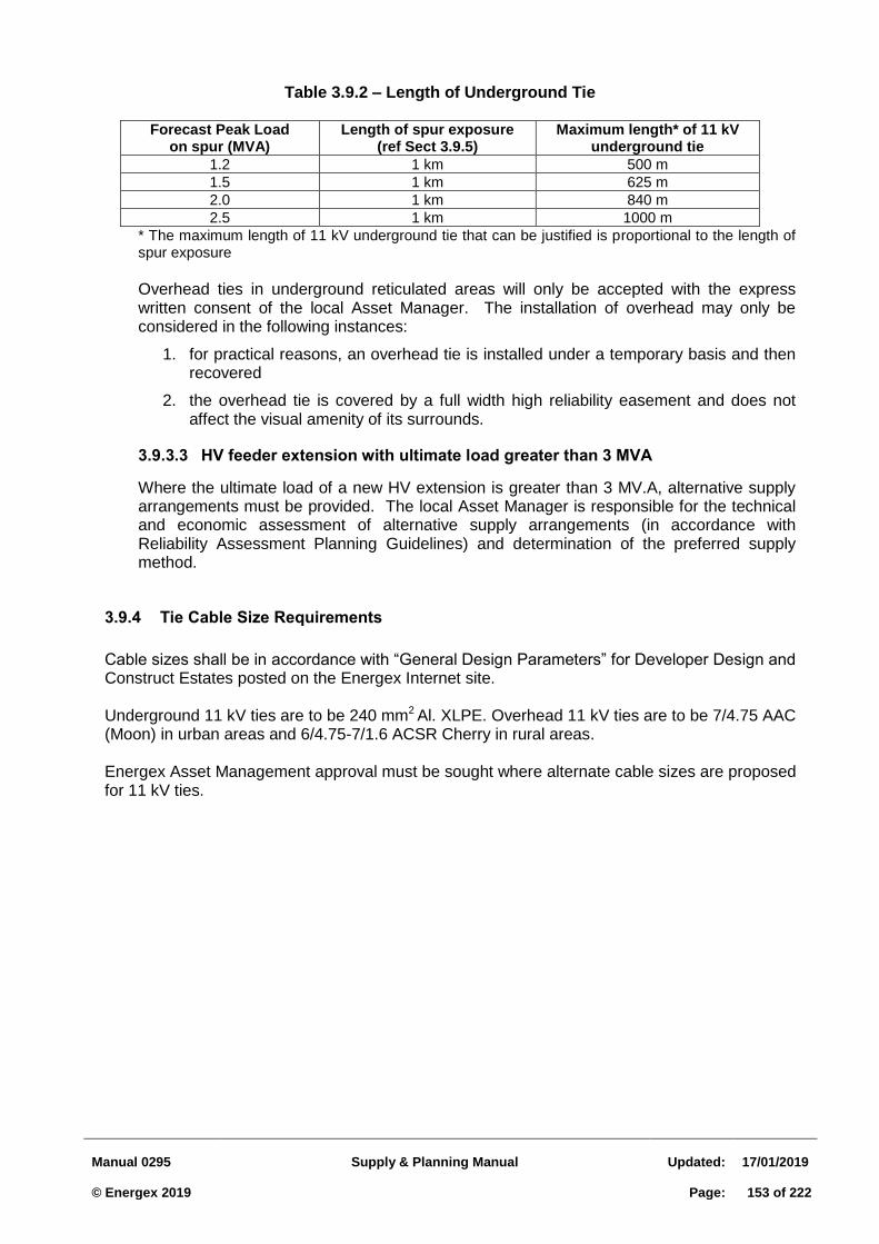
Manual 0295
Supply & Planning Manual
Updated:
17/01/2019 © Energex 2019
Page:
153 of 222
Table 3.9.2 – Length of Underground Tie
Forecast Peak Load on spur (MVA)
Length of spur exposure (ref Sect 3.9.5)
Maximum length* of 11 kV underground tie
1.2 1 km 500 m
1.5 1 km 625 m
2.0 1 km 840 m
2.5 1 km 1000 m
* The maximum length of 11 kV underground tie that can be justified is proportional to the length of spur exposure
Overhead ties in underground reticulated areas will only be accepted with the express written consent of the local Asset Manager. The installation of overhead may only be considered in the following instances:
1. for practical reasons, an overhead tie is installed under a temporary basis and then recovered
2. the overhead tie is covered by a full width high reliability easement and does not affect the visual amenity of its surrounds.
HV feeder extension with ultimate load greater than 3 MVA 3.9.3.3
Where the ultimate load of a new HV extension is greater than 3 MV.A, alternative supply arrangements must be provided. The local Asset Manager is responsible for the technical and economic assessment of alternative supply arrangements (in accordance with Reliability Assessment Planning Guidelines) and determination of the preferred supply method.
3.9.4 Tie Cable Size Requirements
Cable sizes shall be in accordance with “General Design Parameters” for Developer Design and Construct Estates posted on the Energex Internet site.
Underground 11 kV ties are to be 240 mm2
Al. XLPE. Overhead 11 kV ties are to be 7/4.75 AAC (Moon) in urban areas and 6/4.75-7/1.6 ACSR Cherry in rural areas.
Energex Asset Management approval must be sought where alternate cable sizes are proposed for 11 kV ties.
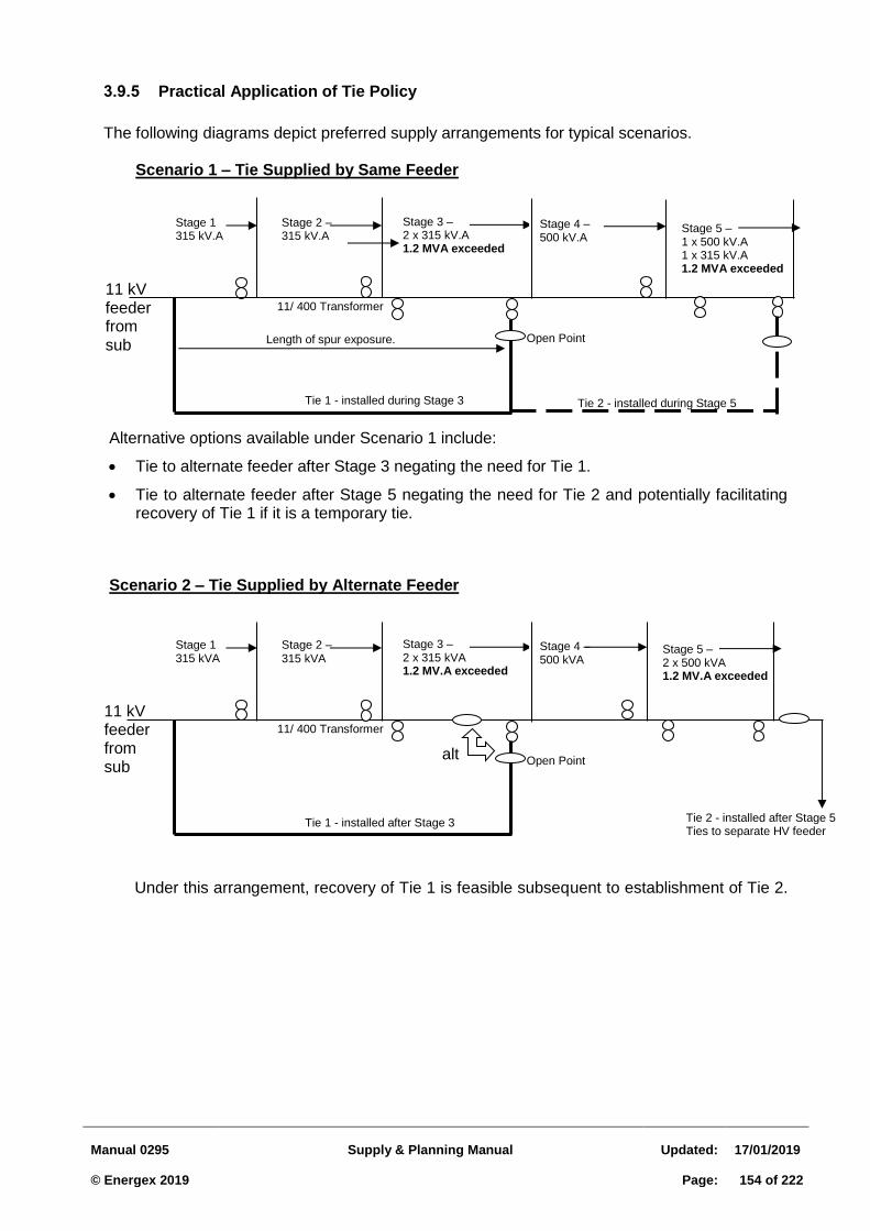
Manual 0295
Supply & Planning Manual
Updated:
17/01/2019 © Energex 2019
Page:
154 of 222
3.9.5 Practical Application of Tie Policy
The following diagrams depict preferred supply arrangements for typical scenarios.
Scenario 1 – Tie Supplied by Same Feeder
Alternative options available under Scenario 1 include:
Tie to alternate feeder after Stage 3 negating the need for Tie 1.
Tie to alternate feeder after Stage 5 negating the need for Tie 2 and potentially facilitating recovery of Tie 1 if it is a temporary tie.
Scenario 2 – Tie Supplied by Alternate Feeder
Under this arrangement, recovery of Tie 1 is feasible subsequent to establishment of Tie 2.
Stage 1 315 kVA
Stage 2 – 315 kVA
Stage 3 – 2 x 315 kVA 1.2 MV.A exceeded
11 kV feeder from sub
Tie 1 - installed after Stage 3
11/ 400 Transformer
Stage 4 – 500 kVA
Stage 5 – 2 x 500 kVA 1.2 MV.A exceeded
Tie 2 - installed after Stage 5 Ties to separate HV feeder
Open Point
Stage 1 315 kV.A
Stage 2 – 315 kV.A
Stage 3 – 2 x 315 kV.A 1.2 MVA exceeded
11 kV feeder from sub
Tie 1 - installed during Stage 3
11/ 400 Transformer
Stage 4 – 500 kV.A
Stage 5 – 1 x 500 kV.A 1 x 315 kV.A 1.2 MVA exceeded
Open Point
Tie 2 - installed during Stage 5
Length of spur exposure.
alt
Manual 0295
Supply & Planning Manual
Updated:
17/01/2019 © Energex 2019
Page:
155 of 222
4 QUALITY OF SUPPLY
4.1 CUSTOMER CONNECTION REQUIREMENTS
Because the supply system is a shared resource, customers have an obligation to ensure that their plant and equipment does not cause interference to other customers. Customers should also ensure that their equipment will operate satisfactorily when connected to the network. This section sets out the standard requirements Energex imposes on individual customer installations and equipment to ensure the desired supply quality is maintained for all customers. It specifically applies to:
customers taking supply under tariff arrangements
contestable customers taking supply under a standard connection agreement
contestable customers taking supply under a negotiated connection agreement which does not vary these requirements (these agreements may be subject to varied or additional requirements).
The limits have been established consistent with the National Electricity Rules (NER), Electricity Regulations, relevant Australian standards, internal conditions of supply, and best Australian and international industry practice. Particular provisions of this standard may be waived or varied at the discretion of Energex, provided there is no potential to adversely affect the supply to other customers. In general, these requirements are specified for "normal system operating conditions". During abnormal system operation and system emergencies, when major items of plant are out of service, these requirements may be varied by Energex. Compliance with these requirements is assessed at the customer’s connection point, which is the agreed point of supply established with Energex.
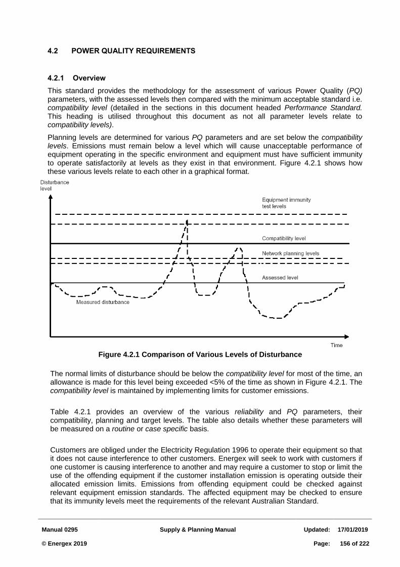
Manual 0295
Supply & Planning Manual
Updated:
17/01/2019 © Energex 2019
Page:
156 of 222
4.2 POWER QUALITY REQUIREMENTS
4.2.1 Overview
This standard provides the methodology for the assessment of various Power Quality (PQ) parameters, with the assessed levels then compared with the minimum acceptable standard i.e. compatibility level (detailed in the sections in this document headed Performance Standard. This heading is utilised throughout this document as not all parameter levels relate to compatibility levels).
Planning levels are determined for various PQ parameters and are set below the compatibility levels. Emissions must remain below a level which will cause unacceptable performance of equipment operating in the specific environment and equipment must have sufficient immunity to operate satisfactorily at levels as they exist in that environment. Figure 4.2.1 shows how these various levels relate to each other in a graphical format.
Figure 4.2.1 Comparison of Various Levels of Disturbance
The normal limits of disturbance should be below the compatibility level for most of the time, an allowance is made for this level being exceeded <5% of the time as shown in Figure 4.2.1. The compatibility level is maintained by implementing limits for customer emissions.
Table 4.2.1 provides an overview of the various reliability and PQ parameters, their compatibility, planning and target levels. The table also details whether these parameters will be measured on a routine or case specific basis.
Customers are obliged under the Electricity Regulation 1996 to operate their equipment so that it does not cause interference to other customers. Energex will seek to work with customers if one customer is causing interference to another and may require a customer to stop or limit the use of the offending equipment if the customer installation emission is operating outside their allocated emission limits. Emissions from offending equipment could be checked against relevant equipment emission standards. The affected equipment may be checked to ensure that its immunity levels meet the requirements of the relevant Australian Standard.
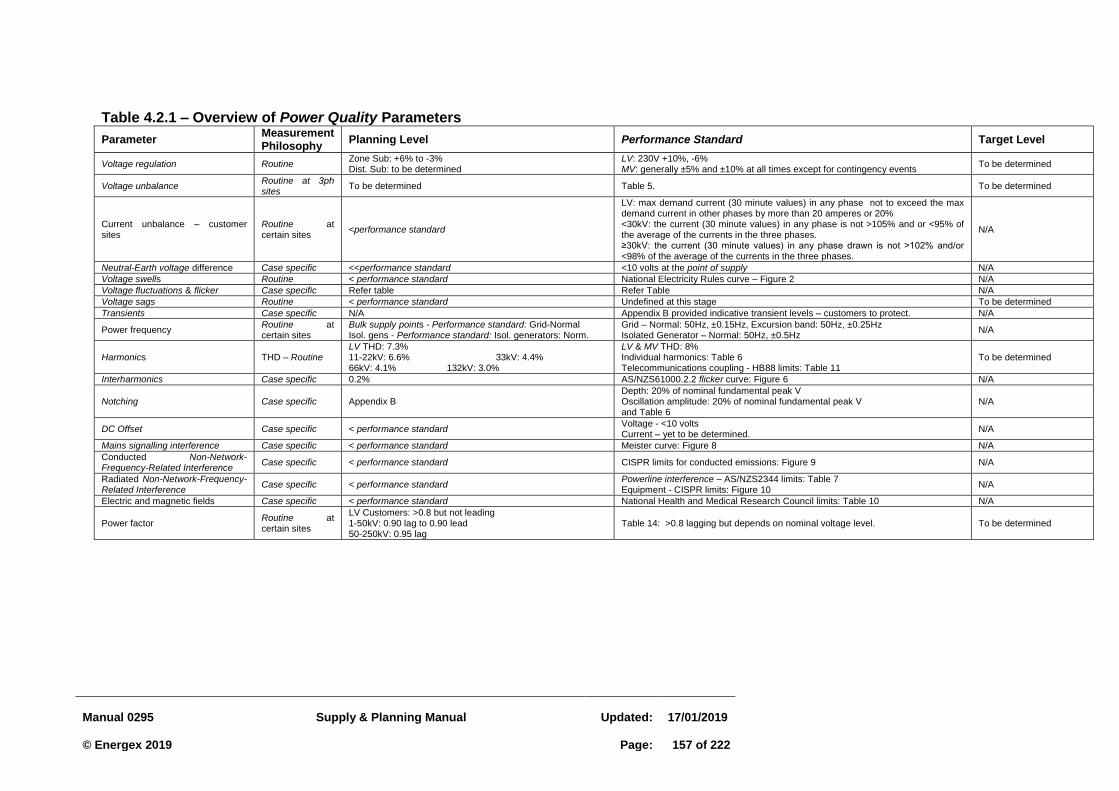
Manual 0295
Supply & Planning Manual
Updated:
17/01/2019 © Energex 2019
Page:
157 of 222
Table 4.2.1 – Overview of Power Quality Parameters
Parameter Measurement Philosophy
Planning Level Performance Standard Target Level
Voltage regulation Routine Zone Sub: +6% to -3% Dist. Sub: to be determined
LV: 230V +10%, -6% MV: generally ±5% and ±10% at all times except for contingency events
To be determined
Voltage unbalance Routine at 3ph sites
To be determined Table 5. To be determined
Current unbalance – customer sites
Routine at certain sites
<performance standard
LV: max demand current (30 minute values) in any phase not to exceed the max demand current in other phases by more than 20 amperes or 20% <30kV: the current (30 minute values) in any phase is not >105% and or <95% of the average of the currents in the three phases. ≥30kV: the current (30 minute values) in any phase drawn is not >102% and/or <98% of the average of the currents in the three phases.
N/A
Neutral-Earth voltage difference Case specific <<performance standard <10 volts at the point of supply N/A
Voltage swells Routine < performance standard National Electricity Rules curve – Figure 2 N/A
Voltage fluctuations & flicker Case specific Refer table Refer Table N/A
Voltage sags Routine < performance standard Undefined at this stage To be determined
Transients Case specific N/A Appendix B provided indicative transient levels – customers to protect. N/A
Power frequency Routine at certain sites
Bulk supply points - Performance standard: Grid-Normal Isol. gens - Performance standard: Isol. generators: Norm.
Grid – Normal: 50Hz, ±0.15Hz, Excursion band: 50Hz, ±0.25Hz Isolated Generator – Normal: 50Hz, ±0.5Hz
N/A
Harmonics THD – Routine LV THD: 7.3% 11-22kV: 6.6% 33kV: 4.4% 66kV: 4.1% 132kV: 3.0%
LV & MV THD: 8% Individual harmonics: Table 6 Telecommunications coupling - HB88 limits: Table 11
To be determined
Interharmonics Case specific 0.2% AS/NZS61000.2.2 flicker curve: Figure 6 N/A
Notching Case specific Appendix B Depth: 20% of nominal fundamental peak V Oscillation amplitude: 20% of nominal fundamental peak V and Table 6
N/A
DC Offset Case specific < performance standard Voltage - <10 volts Current – yet to be determined.
N/A
Mains signalling interference Case specific < performance standard Meister curve: Figure 8 N/A
Conducted Non-Network-Frequency-Related Interference
Case specific < performance standard CISPR limits for conducted emissions: Figure 9 N/A
Radiated Non-Network-Frequency-Related Interference
Case specific < performance standard Powerline interference – AS/NZS2344 limits: Table 7 Equipment - CISPR limits: Figure 10
N/A
Electric and magnetic fields Case specific < performance standard National Health and Medical Research Council limits: Table 10 N/A
Power factor Routine at certain sites
LV Customers: >0.8 but not leading 1-50kV: 0.90 lag to 0.90 lead 50-250kV: 0.95 lag
Table 14: >0.8 lagging but depends on nominal voltage level. To be determined
Manual 0295
Supply & Planning Manual
Updated:
17/01/2019 © Energex 2019
Page:
158 of 222
4.2.2 Voltage Regulation
Parameter Description 4.2.2.1
The voltage that customers receive is constantly changing in value due to the loads being drawn by all customers and the response of the network and its automatic regulating equipment to this changing load. The level of variation that occurs is the voltage regulation at that site.
Performance Standard 4.2.2.2
Low voltage customers The compatibility level for voltage regulation on low voltage networks is legislated for Queensland in the Electricity (Voltage Limits) Amendment Regulation 2017, which has adopted the values set out in AS60038, namely 230 volts and 400 volts rms, plus 10% or minus 6%.
Other customers The standard voltage at a customer’s consumer terminals supplied at high voltage of 22000V or less with the allowable margin of 5% in accordance with the Electricity Regulation 2006.
The National Electricity Rules2 allows for connection agreements with customers to detail the expected voltage range. Otherwise the National Electricity Rules requires rms phase voltages to generally remain between ±5% of the target voltage (determined in consultation with NEMMCO), provided that at all times the supply voltage remains between ±10% of the nominal rms phase to phase voltage, except as a consequence of a contingency event which are allowed for in this standard at Section 1.2.5 - Voltage Swells.
Assessment Method 4.2.2.3
Voltage regulation is measured using the average voltage of 10 minute intervals at the point of supply. The minimum measurement interval is one week.3 The agreed load or network capacity of dedicated customer connection assets should not be exceeded during the measurement period. Network capacity should also account for the voltage drop of the dedicated customer connection assets.
Assessment Level 4.2.2.4
The assessed levels should not exceed the performance standard. AS 60038 and the National Electricity Rules allow for variations that might occur as a result of system switching or abnormal events as follows, but care should be exercised for disputes:
AS 60038 allows for variances due to system switching and temporary voltage variations.
2 AS60038 requires steady-state voltages greater than 1kV and not exceeding 35kV to remain between ±10% of the
nominal voltage measured at the point of supply but excluding “voltage transients, such as those due to system switching, and temporary voltage variations”. This is overridden by the requirements as detailed from the National Electricity Rules.
3 AS/NZS 61000.4.30
Manual 0295
Supply & Planning Manual
Updated:
17/01/2019 © Energex 2019
Page:
159 of 222
The National Electricity Rules allows for 10% variance above or below nominal voltage, excluding contingency events which are allowed for in this standard at Section 1.2.5 - Voltage Swells.
Additional Information 4.2.2.5
AS 60038:2012 details a nominal voltage of 230 volts and an expected range of plus 10% and minus 6%. Until October 2018, Queensland utilities followed the previously legislated values of 240 volts plus or minus 6%, which generally fits within the range allowed by the newer 2017 regulation.
An additional 5% voltage drop is allowed within the customer premise4 and is reflected in the utilization voltage range.
4.2.3 Voltage Unbalance
Parameter Description 4.2.3.1
Voltage unbalance is where the rms values of line to line voltages (fundamental component) or the phase angles between them are not all equal in a polyphase system. It is caused by uneven system impedances or uneven connection of loads within premises or on low or medium voltage networks.
Voltage unbalance is to be expressed as a percentage of negative sequence voltage to the positive sequence voltage, generally using line to line values.
Performance Standard 4.2.3.2
The performance standard for voltage unbalance for is provided by the National Electricity Rules as:
The average voltage unbalance, except as a consequence of a contingency event, shall be measured using 30-minute averages and should not exceed the values in Column 2 of Table 4.2.2.
The average voltage unbalance, as a consequence of a contingency event, shall be measured using 30-minute averages and should not exceed the values in Column 3 of Table 4.2.2.
The average voltage unbalance shall be measured using 10-minute averages and should not exceed the values in Column 4 of Table 4.2.2.
The average voltage unbalance should not vary more often than once per hour by more than the values in Column 5 of Table 4.2.2 measured using 1-minute average values.
4 AS/NZS3000
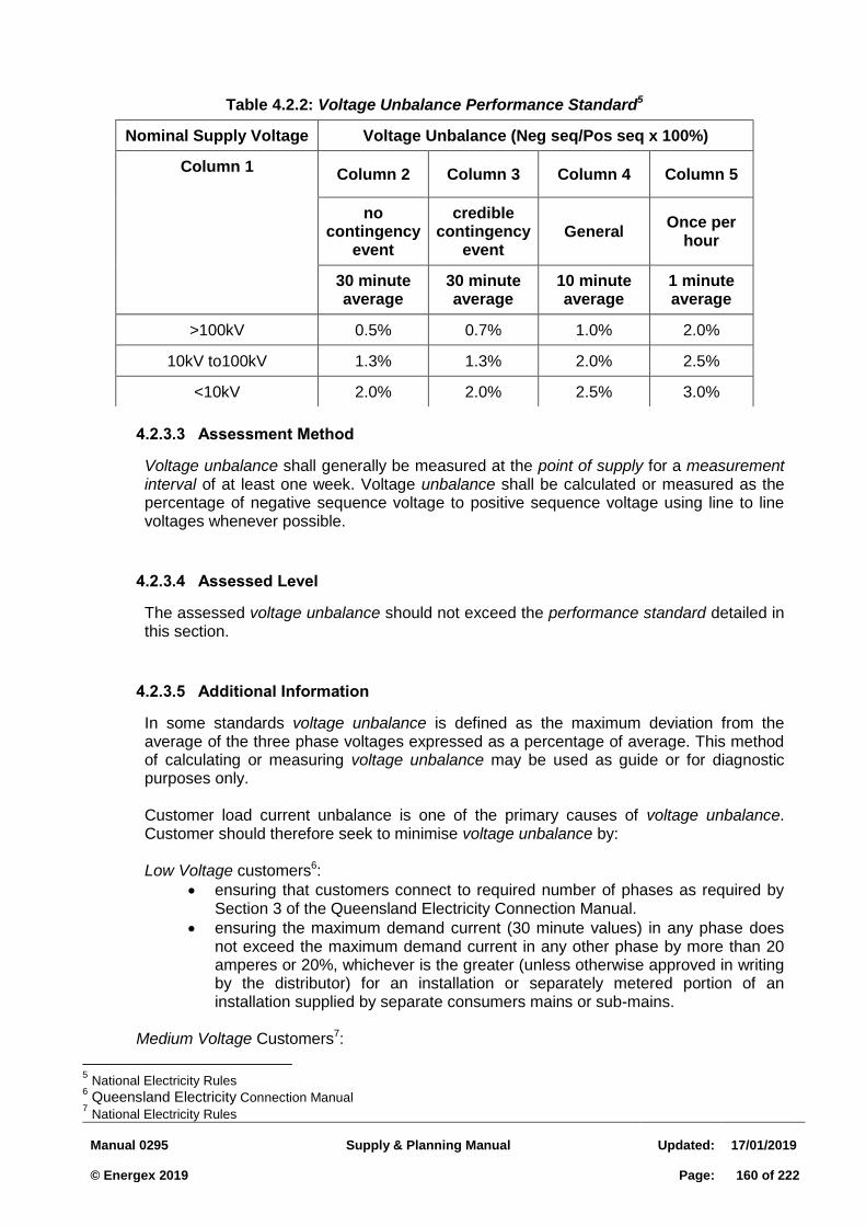
Manual 0295
Supply & Planning Manual
Updated:
17/01/2019 © Energex 2019
Page:
160 of 222
Assessment Method 4.2.3.3
Voltage unbalance shall generally be measured at the point of supply for a measurement interval of at least one week. Voltage unbalance shall be calculated or measured as the percentage of negative sequence voltage to positive sequence voltage using line to line voltages whenever possible.
Assessed Level 4.2.3.4
The assessed voltage unbalance should not exceed the performance standard detailed in this section.
Additional Information 4.2.3.5
In some standards voltage unbalance is defined as the maximum deviation from the average of the three phase voltages expressed as a percentage of average. This method of calculating or measuring voltage unbalance may be used as guide or for diagnostic purposes only.
Customer load current unbalance is one of the primary causes of voltage unbalance. Customer should therefore seek to minimise voltage unbalance by:
Low Voltage customers6:
ensuring that customers connect to required number of phases as required by Section 3 of the Queensland Electricity Connection Manual.
ensuring the maximum demand current (30 minute values) in any phase does not exceed the maximum demand current in any other phase by more than 20 amperes or 20%, whichever is the greater (unless otherwise approved in writing by the distributor) for an installation or separately metered portion of an installation supplied by separate consumers mains or sub-mains.
Medium Voltage Customers7:
5 National Electricity Rules
6 Queensland Electricity Connection Manual
7 National Electricity Rules
Table 4.2.2: Voltage Unbalance Performance Standard5
Nominal Supply Voltage Voltage Unbalance (Neg seq/Pos seq x 100%)
Column 1 Column 2 Column 3 Column 4 Column 5
no contingency
event
credible contingency
event General
Once per hour
30 minute average
30 minute average
10 minute average
1 minute average
>100kV 0.5% 0.7% 1.0% 2.0%
10kV to100kV 1.3% 1.3% 2.0% 2.5%
<10kV 2.0% 2.0% 2.5% 3.0%
Manual 0295
Supply & Planning Manual
Updated:
17/01/2019 © Energex 2019
Page:
161 of 222
as contracted; otherwise:
for connections at voltages less than 30kV, the current (30 minute values) in any phase drawn by their installation is not greater than 105% and or less than 95% of the average of the currents in the three phases.
for connections at 30kV or higher voltage, the current (30 minute values) in any phase drawn by their installation is not greater than 102% and or less than 98% of the average of the currents in the three phases.
4.2.4 Neutral to Earth Voltage Difference
Parameter Description 4.2.4.1
Neutral to earth voltage difference is the difference in voltage between the neutral conductor and the general mass of earth as measured at a particular point on the network or within a premise.
Performance Standard 4.2.4.2
The performance standard for alternating voltage differences between the neutral and earth is less than 10 volts at the point of supply.
Assessment Method 4.2.4.3
Instantaneous rms voltage readings may be taken at normal and greater than normal load. Logging using voltage recording equipment may be necessary to ensure that the limit is not exceeded when the neutral conductor is at peak load.
Assessed Levels 4.2.4.4
The assessed levels should not exceed the 10 volt performance standard for all load conditions.
Additional Information 4.2.4.5
Neutral to earth voltage differences occur due to resistance of the earthing system and the voltage drop in the neutral conductor caused by the neutral current. Neutral to earth voltage differences may be temporary, transient, steady-state or a combination of these. It is preferable to maintain neutral to earth voltages to much less than 10 volts due to the nuisance complaints that would otherwise result. A network neutral connection may be faulty even though the performance standard is maintained as there are often multiple parallel paths for the neutral current to return to the transformer which minimises the voltage drop across the faulty mains connector and the neutral to earth voltage. Customers should install equipotential bonding to Australian Standard AS/NZS 3000 (Wiring Rules) to minimise nuisance tingles from neutral to earth voltages. Standards do not presently provide a compatibility levels for neutral to earth voltage differences, though AS/NZS 60479 details the effects of current through the human body.
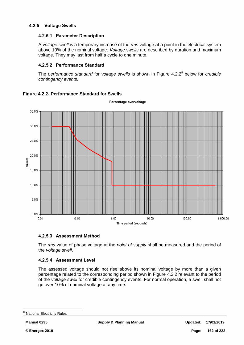
Manual 0295
Supply & Planning Manual
Updated:
17/01/2019 © Energex 2019
Page:
162 of 222
4.2.5 Voltage Swells
Parameter Description 4.2.5.1
A voltage swell is a temporary increase of the rms voltage at a point in the electrical system above 10% of the nominal voltage. Voltage swells are described by duration and maximum voltage. They may last from half a cycle to one minute.
Performance Standard 4.2.5.2
The performance standard for voltage swells is shown in Figure 4.2.28 below for credible contingency events.
Assessment Method 4.2.5.3
The rms value of phase voltage at the point of supply shall be measured and the period of the voltage swell.
Assessment Level 4.2.5.4
The assessed voltage should not rise above its nominal voltage by more than a given percentage related to the corresponding period shown in Figure 4.2.2 relevant to the period of the voltage swell for credible contingency events. For normal operation, a swell shall not go over 10% of nominal voltage at any time.
8 National Electricity Rules
Figure 4.2.2- Performance Standard for Swells
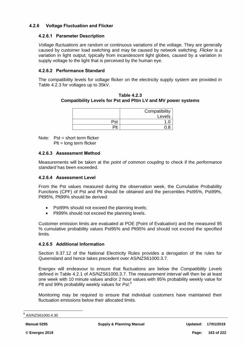
Manual 0295
Supply & Planning Manual
Updated:
17/01/2019 © Energex 2019
Page:
163 of 222
4.2.6 Voltage Fluctuation and Flicker
Parameter Description 4.2.6.1
Voltage fluctuations are random or continuous variations of the voltage. They are generally caused by customer load switching and may be caused by network switching. Flicker is a variation in light output, typically from incandescent light globes, caused by a variation in supply voltage to the light that is perceived by the human eye.
Performance Standard 4.2.6.2
The compatibility levels for voltage flicker on the electricity supply system are provided in Table 4.2.3 for voltages up to 35kV.
Table 4.2.3 Compatibility Levels for Pst and Pltin LV and MV power systems
Compatibility Levels
Pst 1.0
Plt 0.8
Note: Pst = short term flicker Plt = long term flicker
Assessment Method 4.2.6.3
Measurements will be taken at the point of common coupling to check if the performance standard has been exceeded.
Assessment Level 4.2.6.4
From the Pst values measured during the observation week, the Cumulative Probability Functions (CPF) of Pst and Plt should be obtained and the percentiles Pst95%, Pst99%, Plt95%, Plt99% should be derived:
Pst99% should not exceed the planning levels;
Plt99% should not exceed the planning levels. Customer emission limits are evaluated at POE (Point of Evaluation) and the measured 95 % cumulative probability values Pst95% and Plt95% and should not exceed the specified limits.
Additional Information 4.2.6.5
Section 9.37.12 of the National Electricity Rules provides a derogation of the rules for Queensland and hence takes precedent over AS/NZS61000.3.7. Energex will endeavour to ensure that fluctuations are below the Compatibility Levels defined in Table 4.2.1 of AS/NZS61000.3.7. The measurement interval will then be at least one week with 10 minute values and/or 2 hour values with 95% probability weekly value for Plt and 99% probability weekly values for Pst.9 Monitoring may be required to ensure that individual customers have maintained their fluctuation emissions below their allocated limits.
9 AS/NZS61000.4.30
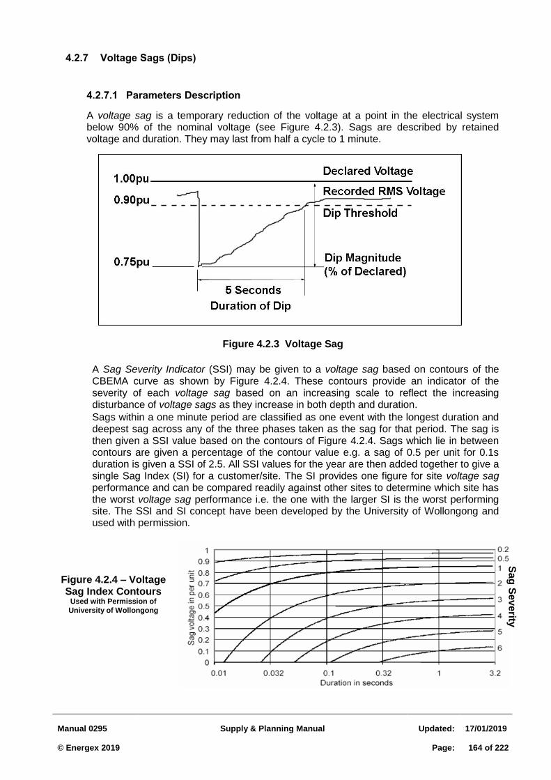
Manual 0295
Supply & Planning Manual
Updated:
17/01/2019 © Energex 2019
Page:
164 of 222
4.2.7 Voltage Sags (Dips)
Parameters Description 4.2.7.1
A voltage sag is a temporary reduction of the voltage at a point in the electrical system below 90% of the nominal voltage (see Figure 4.2.3). Sags are described by retained voltage and duration. They may last from half a cycle to 1 minute.
Figure 4.2.3 Voltage Sag
A Sag Severity Indicator (SSI) may be given to a voltage sag based on contours of the CBEMA curve as shown by Figure 4.2.4. These contours provide an indicator of the severity of each voltage sag based on an increasing scale to reflect the increasing disturbance of voltage sags as they increase in both depth and duration.
Sags within a one minute period are classified as one event with the longest duration and deepest sag across any of the three phases taken as the sag for that period. The sag is then given a SSI value based on the contours of Figure 4.2.4. Sags which lie in between contours are given a percentage of the contour value e.g. a sag of 0.5 per unit for 0.1s duration is given a SSI of 2.5. All SSI values for the year are then added together to give a single Sag Index (SI) for a customer/site. The SI provides one figure for site voltage sag performance and can be compared readily against other sites to determine which site has the worst voltage sag performance i.e. the one with the larger SI is the worst performing site. The SSI and SI concept have been developed by the University of Wollongong and used with permission.
Figure 4.2.4 – Voltage Sag Index Contours
Used with Permission of
University of Wollongong
Sa
g S
eve
rity
Ind
ex
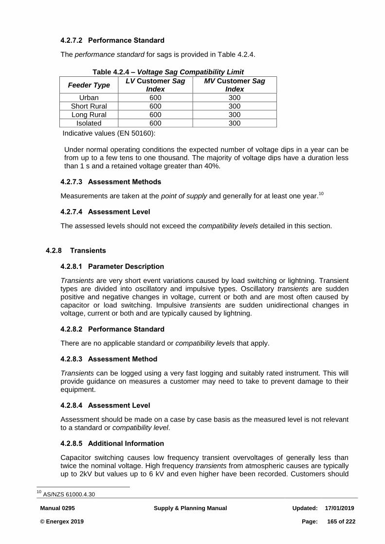
Manual 0295
Supply & Planning Manual
Updated:
17/01/2019 © Energex 2019
Page:
165 of 222
Performance Standard 4.2.7.2
The performance standard for sags is provided in Table 4.2.4.
Indicative values (EN 50160): Under normal operating conditions the expected number of voltage dips in a year can be from up to a few tens to one thousand. The majority of voltage dips have a duration less than 1 s and a retained voltage greater than 40%.
Assessment Methods 4.2.7.3
Measurements are taken at the point of supply and generally for at least one year.10
Assessment Level 4.2.7.4
The assessed levels should not exceed the compatibility levels detailed in this section.
4.2.8 Transients
Parameter Description 4.2.8.1
Transients are very short event variations caused by load switching or lightning. Transient types are divided into oscillatory and impulsive types. Oscillatory transients are sudden positive and negative changes in voltage, current or both and are most often caused by capacitor or load switching. Impulsive transients are sudden unidirectional changes in voltage, current or both and are typically caused by lightning.
Performance Standard 4.2.8.2
There are no applicable standard or compatibility levels that apply.
Assessment Method 4.2.8.3
Transients can be logged using a very fast logging and suitably rated instrument. This will provide guidance on measures a customer may need to take to prevent damage to their equipment.
Assessment Level 4.2.8.4
Assessment should be made on a case by case basis as the measured level is not relevant to a standard or compatibility level.
Additional Information 4.2.8.5
Capacitor switching causes low frequency transient overvoltages of generally less than twice the nominal voltage. High frequency transients from atmospheric causes are typically up to 2kV but values up to 6 kV and even higher have been recorded. Customers should
10
AS/NZS 61000.4.30
Table 4.2.4 – Voltage Sag Compatibility Limit
Feeder Type LV Customer Sag
Index MV Customer Sag
Index
Urban 600 300
Short Rural 600 300
Long Rural 600 300
Isolated 600 300
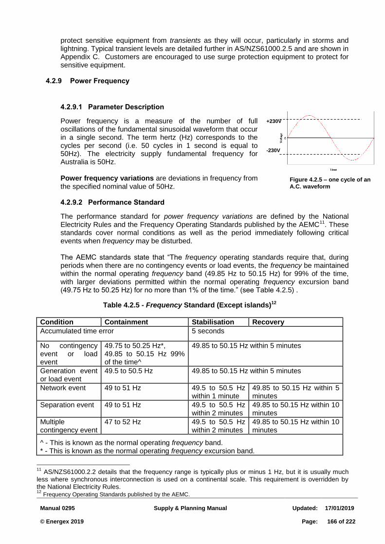
Manual 0295
Supply & Planning Manual
Updated:
17/01/2019 © Energex 2019
Page:
166 of 222
Figure 4.2.5 – one cycle of an
A.C. waveform
+230V
-230V
protect sensitive equipment from transients as they will occur, particularly in storms and lightning. Typical transient levels are detailed further in AS/NZS61000.2.5 and are shown in Appendix C. Customers are encouraged to use surge protection equipment to protect for sensitive equipment.
4.2.9 Power Frequency
Parameter Description 4.2.9.1
Power frequency is a measure of the number of full oscillations of the fundamental sinusoidal waveform that occur in a single second. The term hertz (Hz) corresponds to the cycles per second (i.e. 50 cycles in 1 second is equal to 50Hz). The electricity supply fundamental frequency for Australia is 50Hz. Power frequency variations are deviations in frequency from the specified nominal value of 50Hz.
Performance Standard 4.2.9.2
The performance standard for power frequency variations are defined by the National Electricity Rules and the Frequency Operating Standards published by the AEMC11. These standards cover normal conditions as well as the period immediately following critical events when frequency may be disturbed. The AEMC standards state that “The frequency operating standards require that, during periods when there are no contingency events or load events, the frequency be maintained within the normal operating frequency band (49.85 Hz to 50.15 Hz) for 99% of the time, with larger deviations permitted within the normal operating frequency excursion band (49.75 Hz to 50.25 Hz) for no more than 1% of the time.” (see Table 4.2.5) .
11
AS/NZS61000.2.2 details that the frequency range is typically plus or minus 1 Hz, but it is usually much less where synchronous interconnection is used on a continental scale. This requirement is overridden by the National Electricity Rules. 12
Frequency Operating Standards published by the AEMC.
Table 4.2.5 - Frequency Standard (Except islands)12
Condition Containment Stabilisation Recovery
Accumulated time error 5 seconds
No contingency event or load event
49.75 to 50.25 Hz*, 49.85 to 50.15 Hz 99% of the time^
49.85 to 50.15 Hz within 5 minutes
Generation event or load event
49.5 to 50.5 Hz 49.85 to 50.15 Hz within 5 minutes
Network event 49 to 51 Hz 49.5 to 50.5 Hz within 1 minute
49.85 to 50.15 Hz within 5 minutes
Separation event 49 to 51 Hz 49.5 to 50.5 Hz within 2 minutes
49.85 to 50.15 Hz within 10 minutes
Multiple contingency event
47 to 52 Hz 49.5 to 50.5 Hz within 2 minutes
49.85 to 50.15 Hz within 10 minutes
^ - This is known as the normal operating frequency band. * - This is known as the normal operating frequency excursion band.

Manual 0295
Supply & Planning Manual
Updated:
17/01/2019 © Energex 2019
Page:
167 of 222
The frequency standards in Table 4.2.6 apply to where a part of the national grid that becomes islanded. This table does not strictly apply to isolated systems but will be used by Energex as no other standard applies at this time.
Table 4.2.6 - Frequency Standard for National Grid - Island Conditions13
Condition Containment Stabilisation Recovery
No contingency event or load event 49.5 to 50.5 Hz
Generation event, load event or network event
49 to 51 Hz 49.5 to 50.5 Hz within 5 minutes
The separation event that formed the island
49 to 51 Hz or a wider band notified to NEMMCO by a relevant Jurisdictional Coordinator
49.0 to 51.0 Hz within 2 minutes
49.5 to 50.5 Hz within 10 minutes
Multiple contingency event including a further separation event
47 to 52 Hz 49.0 to 51.0 Hz within 2 minutes
49.5 to 50.5 Hz within 10 minutes
Assessment Method 4.2.9.3
A frequency reading shall be taken every 10 seconds in accordance with AS/NZS61000.4.30.
Assessment Level 4.2.9.4
The assessed variations should not exceed the allowed performance standard detailed in
this section.
4.2.10 Waveform Distortion – Harmonics
Parameter Description 4.2.10.1
Harmonics are frequencies of integer multiples of the fundamental frequency (50 Hz). These harmonic frequencies are caused by non-linear loads, such as electronic equipment and transformers, and result in waveform distortion.
Performance Standard 4.2.10.2
The compatibility levels for harmonics on the electricity supply system are provided in Table 4.2.7 for voltages up to 35kV.
13
Frequency Operating Standards published by the AEMC.
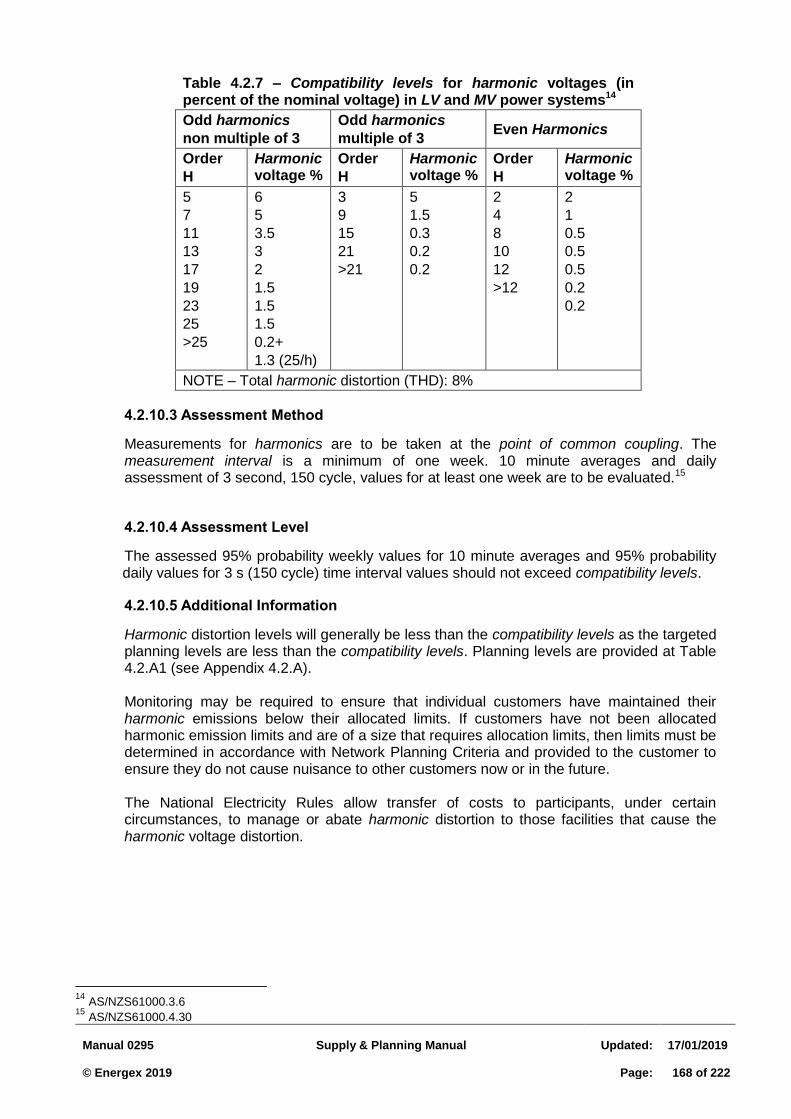
Manual 0295
Supply & Planning Manual
Updated:
17/01/2019 © Energex 2019
Page:
168 of 222
Table 4.2.7 – Compatibility levels for harmonic voltages (in percent of the nominal voltage) in LV and MV power systems14
Odd harmonics
non multiple of 3
Odd harmonics
multiple of 3 Even Harmonics
Order
H
Harmonic voltage %
Order
H
Harmonic voltage %
Order
H
Harmonic voltage %
5
7
11
13
17
19
23
25
>25
6
5
3.5
3
2
1.5
1.5
1.5
0.2+
1.3 (25/h)
3
9
15
21
>21
5
1.5
0.3
0.2
0.2
2
4
8
10
12
>12
2
1
0.5
0.5
0.5
0.2
0.2
NOTE – Total harmonic distortion (THD): 8%
Assessment Method 4.2.10.3
Measurements for harmonics are to be taken at the point of common coupling. The measurement interval is a minimum of one week. 10 minute averages and daily assessment of 3 second, 150 cycle, values for at least one week are to be evaluated.15
Assessment Level 4.2.10.4
The assessed 95% probability weekly values for 10 minute averages and 95% probability daily values for 3 s (150 cycle) time interval values should not exceed compatibility levels.
Additional Information 4.2.10.5
Harmonic distortion levels will generally be less than the compatibility levels as the targeted planning levels are less than the compatibility levels. Planning levels are provided at Table 4.2.A1 (see Appendix 4.2.A). Monitoring may be required to ensure that individual customers have maintained their harmonic emissions below their allocated limits. If customers have not been allocated harmonic emission limits and are of a size that requires allocation limits, then limits must be determined in accordance with Network Planning Criteria and provided to the customer to ensure they do not cause nuisance to other customers now or in the future. The National Electricity Rules allow transfer of costs to participants, under certain circumstances, to manage or abate harmonic distortion to those facilities that cause the harmonic voltage distortion.
14
AS/NZS61000.3.6 15
AS/NZS61000.4.30
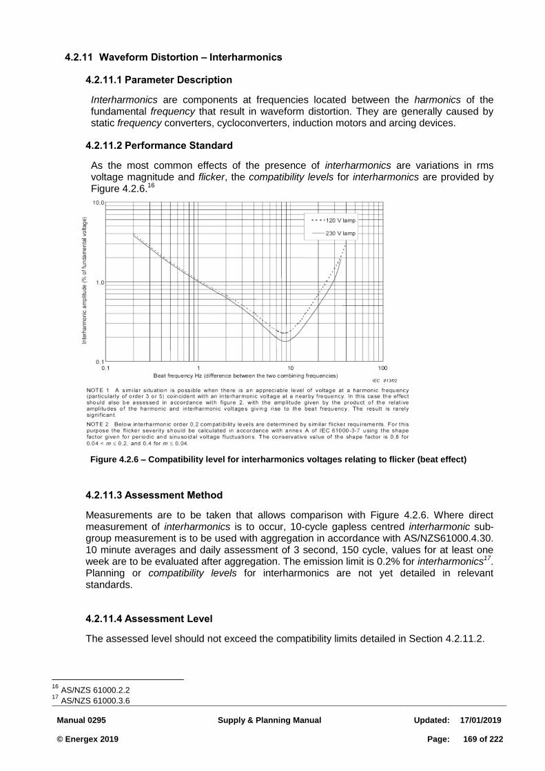
Manual 0295
Supply & Planning Manual
Updated:
17/01/2019 © Energex 2019
Page:
169 of 222
4.2.11 Waveform Distortion – Interharmonics
Parameter Description 4.2.11.1
Interharmonics are components at frequencies located between the harmonics of the fundamental frequency that result in waveform distortion. They are generally caused by static frequency converters, cycloconverters, induction motors and arcing devices.
Performance Standard 4.2.11.2
As the most common effects of the presence of interharmonics are variations in rms voltage magnitude and flicker, the compatibility levels for interharmonics are provided by Figure 4.2.6.16
Assessment Method 4.2.11.3
Measurements are to be taken that allows comparison with Figure 4.2.6. Where direct measurement of interharmonics is to occur, 10-cycle gapless centred interharmonic sub-group measurement is to be used with aggregation in accordance with AS/NZS61000.4.30. 10 minute averages and daily assessment of 3 second, 150 cycle, values for at least one week are to be evaluated after aggregation. The emission limit is 0.2% for interharmonics17. Planning or compatibility levels for interharmonics are not yet detailed in relevant standards.
Assessment Level 4.2.11.4
The assessed level should not exceed the compatibility limits detailed in Section 4.2.11.2.
16
AS/NZS 61000.2.2 17
AS/NZS 61000.3.6
Figure 4.2.6 – Compatibility level for interharmonics voltages relating to flicker (beat effect)
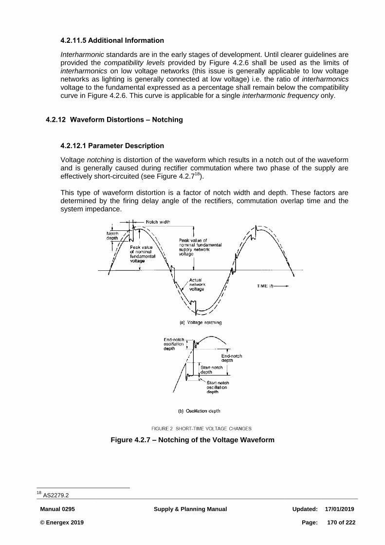
Manual 0295
Supply & Planning Manual
Updated:
17/01/2019 © Energex 2019
Page:
170 of 222
Additional Information 4.2.11.5
Interharmonic standards are in the early stages of development. Until clearer guidelines are provided the compatibility levels provided by Figure 4.2.6 shall be used as the limits of interharmonics on low voltage networks (this issue is generally applicable to low voltage networks as lighting is generally connected at low voltage) i.e. the ratio of interharmonics voltage to the fundamental expressed as a percentage shall remain below the compatibility curve in Figure 4.2.6. This curve is applicable for a single interharmonic frequency only.
4.2.12 Waveform Distortions – Notching
Parameter Description 4.2.12.1
Voltage notching is distortion of the waveform which results in a notch out of the waveform and is generally caused during rectifier commutation where two phase of the supply are effectively short-circuited (see Figure 4.2.718). This type of waveform distortion is a factor of notch width and depth. These factors are determined by the firing delay angle of the rectifiers, commutation overlap time and the system impedance.
Figure 4.2.7 – Notching of the Voltage Waveform
18
AS2279.2
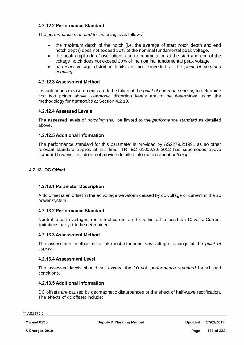
Manual 0295
Supply & Planning Manual
Updated:
17/01/2019 © Energex 2019
Page:
171 of 222
Performance Standard 4.2.12.2
The performance standard for notching is as follows19:
the maximum depth of the notch (i.e. the average of start notch depth and end notch depth) does not exceed 20% of the nominal fundamental peak voltage.
the peak amplitude of oscillations due to commutation at the start and end of the voltage notch does not exceed 20% of the nominal fundamental peak voltage.
harmonic voltage distortion limits are not exceeded at the point of common coupling:
Assessment Method 4.2.12.3
Instantaneous measurements are to be taken at the point of common coupling to determine first two points above. Harmonic distortion levels are to be determined using the methodology for harmonics at Section 4.2.10.
Assessed Levels 4.2.12.4
The assessed levels of notching shall be limited to the performance standard as detailed above.
Additional Information 4.2.12.5
The performance standard for this parameter is provided by AS2279.2:1991 as no other relevant standard applies at this time. TR IEC 61000.3.6:2012 has superseded above standard however this does not provide detailed information about notching.
4.2.13 DC Offset
Parameter Description 4.2.13.1
A dc offset is an offset in the ac voltage waveform caused by dc voltage or current in the ac power system.
Performance Standard 4.2.13.2
Neutral to earth voltages from direct current are to be limited to less than 10 volts. Current limitations are yet to be determined.
Assessment Method 4.2.13.3
The assessment method is to take instantaneous rms voltage readings at the point of supply.
Assessment Level 4.2.13.4
The assessed levels should not exceed the 10 volt performance standard for all load conditions.
Additional Information 4.2.13.5
DC offsets are caused by geomagnetic disturbances or the effect of half-wave rectification. The effects of dc offsets include:
19
AS2279.2
Manual 0295
Supply & Planning Manual
Updated:
17/01/2019 © Energex 2019
Page:
172 of 222
Biasing of transformer cores so they saturate in normal operation and hence additional heating and loss of life; and
Electrolytic erosion of earth electrodes and other connections. Customers loads that are likely to cause large direct current in the neutral are not to be directly connected to the network. An isolating transformer designed to block the direct component is to be used for such loads.
4.2.14 Mains Signalling Interference
Parameter Description 4.2.14.1
Mains signalling interference is interference that may be caused to appliances and equipment by the mains signal transmitted by Energex for the control of certain types of loads such as hot water systems. This signalling is generally a sequence of pulses ranging from 6 seconds to 180 seconds with each pulse between 0.1 and 7 seconds. The frequency used is 1050 Hz.
Performance Standard 4.2.14.2
The performance standard is as provided by the Meister Curve from Figure 8.20
Us = injected sine wave signal voltage; Un = nominal supply voltage.
Assessment Method 4.2.14.3
The measurement interval for main signalling interference is a minimum of one day. Measurements are to be rms values taken at the point of supply.
20
AS/NZS61000.2.12
Figure 4.2.8 – Meister curve for ripple control systems in public networks
(100 Hz to 3 000 Hz)
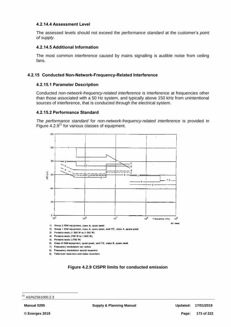
Manual 0295
Supply & Planning Manual
Updated:
17/01/2019 © Energex 2019
Page:
173 of 222
Assessment Level 4.2.14.4
The assessed levels should not exceed the performance standard at the customer’s point of supply.
Additional Information 4.2.14.5
The most common interference caused by mains signalling is audible noise from ceiling fans.
4.2.15 Conducted Non-Network-Frequency-Related Interference
Parameter Description 4.2.15.1
Conducted non-network-frequency-related interference is interference at frequencies other than those associated with a 50 Hz system, and typically above 150 kHz from unintentional sources of interference, that is conducted through the electrical system.
Performance Standard 4.2.15.2
The performance standard for non-network-frequency-related interference is provided in Figure 4.2.921 for various classes of equipment.
21
AS/NZS61000.2.3
Figure 4.2.9 CISPR limits for conducted emission
Manual 0295
Supply & Planning Manual
Updated:
17/01/2019 © Energex 2019
Page:
174 of 222
Assessment Method 4.2.15.3
Non-network-frequency-related conducted interference is assessed by measurement using “a CISPR receiver which contains a quasi-peak weighing circuit designed to give a first-order correlation between the measured quantity and the effect on radio reception produced by various waveforms” as provided by AS/NZS61000.2.3. CISPR 16-1-1 allows for average detectors to be used in certain circumstances. An artificial mains network is required “to provide a defined impedance at high frequencies across the power feed at the point of measurement of terminal voltage, and also to provide isolation of the circuit under test from the ambient noise on the powerlines” (AS/NZS CISPR 22). “The use of a quasi-peak detector is relevant only to interference problems involving the reception of broadcast signals. In more general EMC problems the use of the quasi-peak detector might give misleading information. Similarly, the artificial mains impedance used in the standardised CISPR measurement method may not be valid for other applications” (AS/NZS CISPR 22).
Assessment Level 4.2.15.4
The assessed levels should not exceed those provided by Figure 4.2.9.
Additional Information 4.2.15.5
Customers are obliged under the Electricity Regulation 2006 to operate their equipment so that it does not cause interference to other customers. Energex will seek to work with customers if one customer is causing conducted non-network-frequency interference to another. This may require a customer to stop or limit the use of the offending equipment if Energex is certain the equipment is operating outside the performance standard. It will be beneficial to ensure that the offending equipment is operating outside the requirements of emission standards for dedicated equipment types or product family e.g. AS/NZS CISPR 22 for radio disturbance from information technology equipment. The affected equipment may need to be checked to ensure that its immunity levels meet the requirements of the relevant Australian Standard e.g. AS/NZS61000.4.6 details testing and measurement techniques for immunity testing to conducted disturbances induced by radio-frequency fields. Testing laboratories may be required to conduct equipment emission and immunity testing. Network equipment may also cause problems non-network-frequency-related interference e.g faulty mains signalling electronic relays on customer premise.
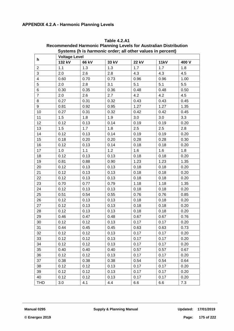
Manual 0295
Supply & Planning Manual
Updated:
17/01/2019 © Energex 2019
Page:
175 of 222
APPENDIX 4.2.A - Harmonic Planning Levels
Table 4.2.A1 Recommended Harmonic Planning Levels for Australian Distribution
Systems (h is harmonic order; all other values in percent)
h Voltage Level
132 kV 66 kV 33 kV 22 kV 11kV 400 V
2 1.1 1.3 1.3 1.7 1.7 1.8
3 2.0 2.6 2.8 4.3 4.3 4.5
4 0.60 0.70 0.73 0.96 0.96 1.00
5 2.0 2.8 3.1 5.1 5.1 5.5
6 0.30 0.35 0.36 0.48 0.48 0.50
7 2.0 2.6 2.7 4.2 4.2 4.5
8 0.27 0.31 0.32 0.43 0.43 0.45
9 0.81 0.92 0.95 1.27 1.27 1.35
10 0.27 0.31 0.32 0.42 0.42 0.45
11 1.5 1.8 1.9 3.0 3.0 3.3
12 0.12 0.13 0.14 0.19 0.19 0.20
13 1.5 1.7 1.8 2.5 2.5 2.8
14 0.12 0.13 0.14 0.19 0.19 0.20
15 0.18 0.20 0.20 0.28 0.28 0.30
16 0.12 0.13 0.14 0.18 0.18 0.20
17 1.0 1.1 1.2 1.6 1.6 1.8
18 0.12 0.13 0.13 0.18 0.18 0.20
19 0.81 0.88 0.90 1.23 1.23 1.35
20 0.12 0.13 0.13 0.18 0.18 0.20
21 0.12 0.13 0.13 0.18 0.18 0.20
22 0.12 0.13 0.13 0.18 0.18 0.20
23 0.70 0.77 0.79 1.18 1.18 1.35
24 0.12 0.13 0.13 0.18 0.18 0.20
25 0.51 0.54 0.55 0.76 0.76 0.85
26 0.12 0.13 0.13 0.18 0.18 0.20
27 0.12 0.13 0.13 0.18 0.18 0.20
28 0.12 0.13 0.13 0.18 0.18 0.20
29 0.46 0.47 0.48 0.67 0.67 0.76
30 0.12 0.12 0.13 0.17 0.17 0.20
31 0.44 0.45 0.45 0.63 0.63 0.73
32 0.12 0.12 0.13 0.17 0.17 0.20
33 0.12 0.12 0.13 0.17 0.17 0.20
34 0.12 0.12 0.13 0.17 0.17 0.20
35 0.40 0.40 0.40 0.57 0.57 0.67
36 0.12 0.12 0.13 0.17 0.17 0.20
37 0.38 0.38 0.38 0.54 0.54 0.64
38 0.12 0.12 0.13 0.17 0.17 0.20
39 0.12 0.12 0.13 0.17 0.17 0.20
40 0.12 0.12 0.13 0.17 0.17 0.20
THD 3.0 4.1 4.4 6.6 6.6 7.3
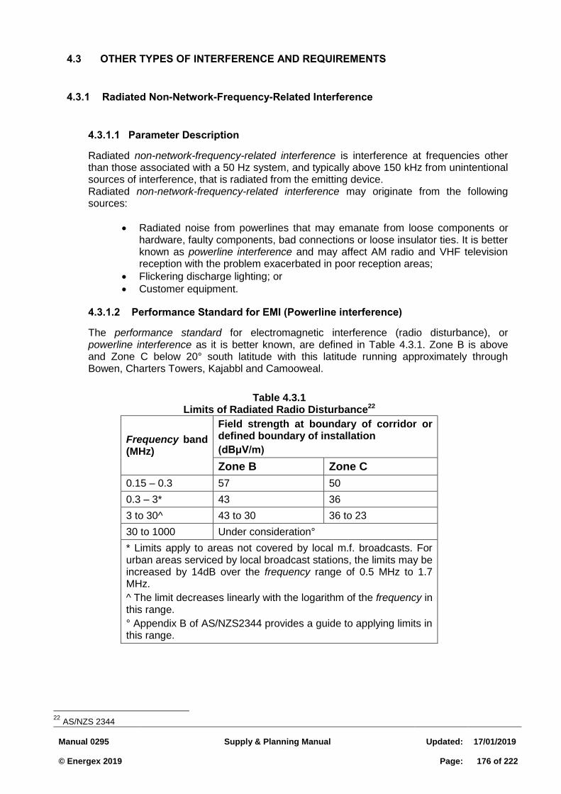
Manual 0295
Supply & Planning Manual
Updated:
17/01/2019 © Energex 2019
Page:
176 of 222
4.3 OTHER TYPES OF INTERFERENCE AND REQUIREMENTS
4.3.1 Radiated Non-Network-Frequency-Related Interference
Parameter Description 4.3.1.1
Radiated non-network-frequency-related interference is interference at frequencies other than those associated with a 50 Hz system, and typically above 150 kHz from unintentional sources of interference, that is radiated from the emitting device. Radiated non-network-frequency-related interference may originate from the following sources:
Radiated noise from powerlines that may emanate from loose components or hardware, faulty components, bad connections or loose insulator ties. It is better known as powerline interference and may affect AM radio and VHF television reception with the problem exacerbated in poor reception areas;
Flickering discharge lighting; or
Customer equipment.
Performance Standard for EMI (Powerline interference) 4.3.1.2
The performance standard for electromagnetic interference (radio disturbance), or powerline interference as it is better known, are defined in Table 4.3.1. Zone B is above and Zone C below 20° south latitude with this latitude running approximately through Bowen, Charters Towers, Kajabbl and Camooweal.
22
AS/NZS 2344
Table 4.3.1 Limits of Radiated Radio Disturbance22
Frequency band (MHz)
Field strength at boundary of corridor or defined boundary of installation
(dBμV/m)
Zone B Zone C
0.15 – 0.3 57 50
0.3 – 3* 43 36
3 to 30^ 43 to 30 36 to 23
30 to 1000 Under consideration°
* Limits apply to areas not covered by local m.f. broadcasts. For urban areas serviced by local broadcast stations, the limits may be increased by 14dB over the frequency range of 0.5 MHz to 1.7 MHz.
^ The limit decreases linearly with the logarithm of the frequency in this range.
° Appendix B of AS/NZS2344 provides a guide to applying limits in this range.
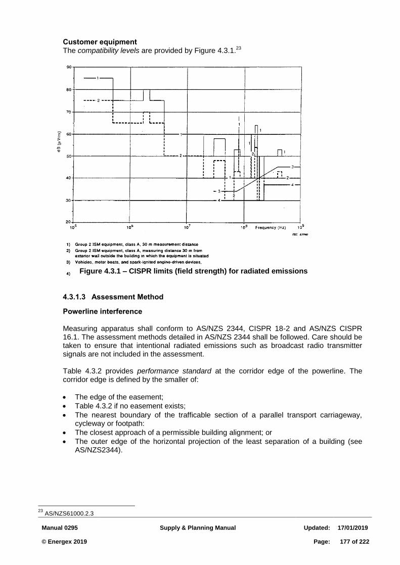
Manual 0295
Supply & Planning Manual
Updated:
17/01/2019 © Energex 2019
Page:
177 of 222
Customer equipment The compatibility levels are provided by Figure 4.3.1.23
Assessment Method 4.3.1.3
Powerline interference Measuring apparatus shall conform to AS/NZS 2344, CISPR 18-2 and AS/NZS CISPR 16.1. The assessment methods detailed in AS/NZS 2344 shall be followed. Care should be taken to ensure that intentional radiated emissions such as broadcast radio transmitter signals are not included in the assessment. Table 4.3.2 provides performance standard at the corridor edge of the powerline. The corridor edge is defined by the smaller of:
The edge of the easement;
Table 4.3.2 if no easement exists;
The nearest boundary of the trafficable section of a parallel transport carriageway, cycleway or footpath:
The closest approach of a permissible building alignment; or
The outer edge of the horizontal projection of the least separation of a building (see AS/NZS2344).
23
AS/NZS61000.2.3
Figure 4.3.1 – CISPR limits (field strength) for radiated emissions
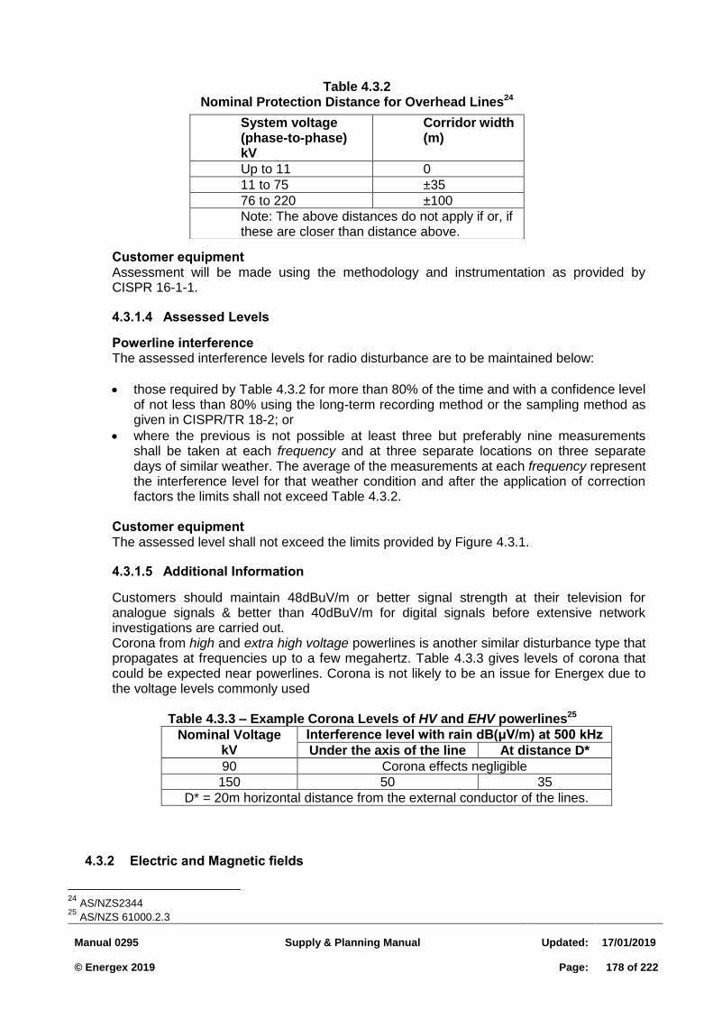
Manual 0295
Supply & Planning Manual
Updated:
17/01/2019 © Energex 2019
Page:
178 of 222
Customer equipment Assessment will be made using the methodology and instrumentation as provided by CISPR 16-1-1.
Assessed Levels 4.3.1.4
Powerline interference The assessed interference levels for radio disturbance are to be maintained below:
those required by Table 4.3.2 for more than 80% of the time and with a confidence level of not less than 80% using the long-term recording method or the sampling method as given in CISPR/TR 18-2; or
where the previous is not possible at least three but preferably nine measurements shall be taken at each frequency and at three separate locations on three separate days of similar weather. The average of the measurements at each frequency represent the interference level for that weather condition and after the application of correction factors the limits shall not exceed Table 4.3.2.
Customer equipment The assessed level shall not exceed the limits provided by Figure 4.3.1.
Additional Information 4.3.1.5
Customers should maintain 48dBuV/m or better signal strength at their television for analogue signals & better than 40dBuV/m for digital signals before extensive network investigations are carried out. Corona from high and extra high voltage powerlines is another similar disturbance type that propagates at frequencies up to a few megahertz. Table 4.3.3 gives levels of corona that could be expected near powerlines. Corona is not likely to be an issue for Energex due to the voltage levels commonly used
Table 4.3.3 – Example Corona Levels of HV and EHV powerlines25
Nominal Voltage kV
Interference level with rain dB(μV/m) at 500 kHz
Under the axis of the line At distance D*
90 Corona effects negligible
150 50 35
D* = 20m horizontal distance from the external conductor of the lines.
4.3.2 Electric and Magnetic fields
24
AS/NZS2344 25
AS/NZS 61000.2.3
Table 4.3.2 Nominal Protection Distance for Overhead Lines24
System voltage (phase-to-phase) kV
Corridor width (m)
Up to 11 0
11 to 75 ±35
76 to 220 ±100
Note: The above distances do not apply if or, if these are closer than distance above.
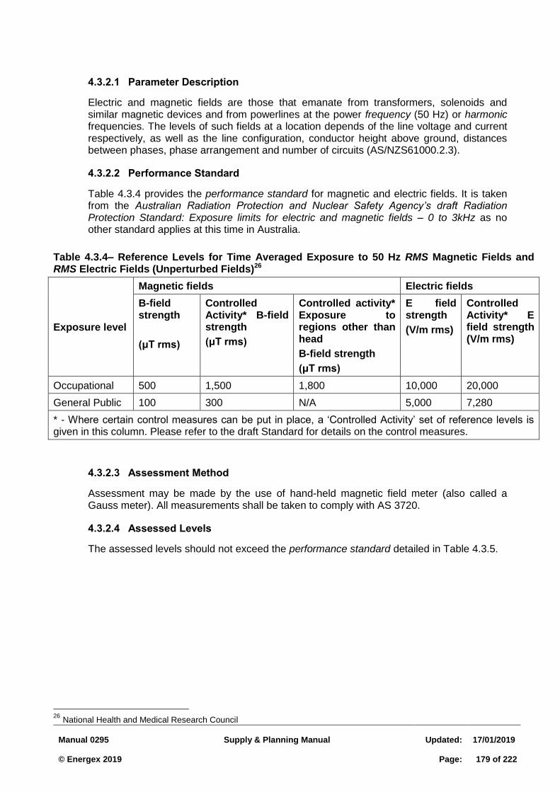
Manual 0295
Supply & Planning Manual
Updated:
17/01/2019 © Energex 2019
Page:
179 of 222
Parameter Description 4.3.2.1
Electric and magnetic fields are those that emanate from transformers, solenoids and similar magnetic devices and from powerlines at the power frequency (50 Hz) or harmonic frequencies. The levels of such fields at a location depends of the line voltage and current respectively, as well as the line configuration, conductor height above ground, distances between phases, phase arrangement and number of circuits (AS/NZS61000.2.3).
Performance Standard 4.3.2.2
Table 4.3.4 provides the performance standard for magnetic and electric fields. It is taken from the Australian Radiation Protection and Nuclear Safety Agency’s draft Radiation Protection Standard: Exposure limits for electric and magnetic fields – 0 to 3kHz as no other standard applies at this time in Australia.
Table 4.3.4– Reference Levels for Time Averaged Exposure to 50 Hz RMS Magnetic Fields and RMS Electric Fields (Unperturbed Fields)26
Exposure level
Magnetic fields Electric fields
B-field strength
(μT rms)
Controlled Activity* B-field strength
(μT rms)
Controlled activity* Exposure to regions other than head
B-field strength
(μT rms)
E field strength
(V/m rms)
Controlled Activity* E field strength (V/m rms)
Occupational 500 1,500 1,800 10,000 20,000
General Public 100 300 N/A 5,000 7,280
* - Where certain control measures can be put in place, a ‘Controlled Activity’ set of reference levels is given in this column. Please refer to the draft Standard for details on the control measures.
Assessment Method 4.3.2.3
Assessment may be made by the use of hand-held magnetic field meter (also called a Gauss meter). All measurements shall be taken to comply with AS 3720.
Assessed Levels 4.3.2.4
The assessed levels should not exceed the performance standard detailed in Table 4.3.5.
26
National Health and Medical Research Council
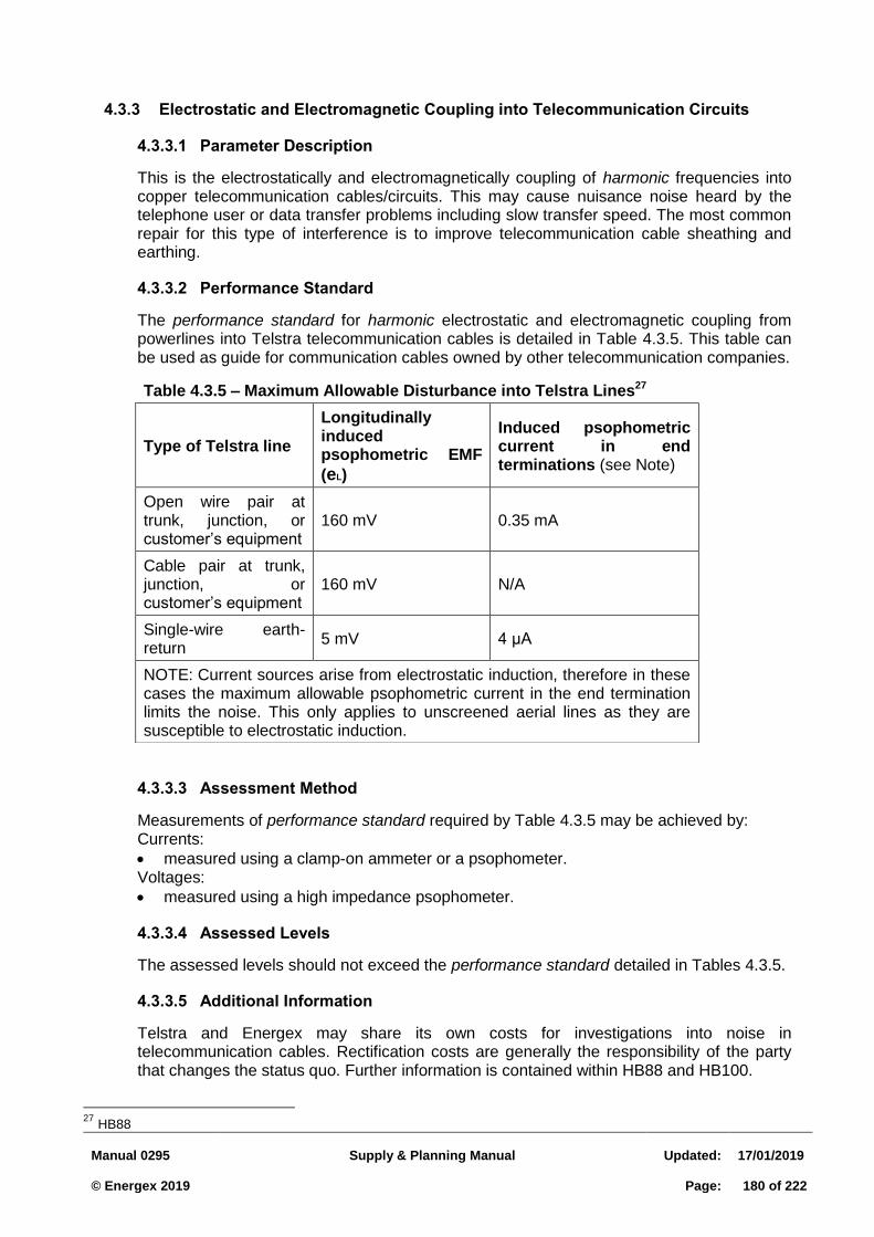
Manual 0295
Supply & Planning Manual
Updated:
17/01/2019 © Energex 2019
Page:
180 of 222
4.3.3 Electrostatic and Electromagnetic Coupling into Telecommunication Circuits
Parameter Description 4.3.3.1
This is the electrostatically and electromagnetically coupling of harmonic frequencies into copper telecommunication cables/circuits. This may cause nuisance noise heard by the telephone user or data transfer problems including slow transfer speed. The most common repair for this type of interference is to improve telecommunication cable sheathing and earthing.
Performance Standard 4.3.3.2
The performance standard for harmonic electrostatic and electromagnetic coupling from powerlines into Telstra telecommunication cables is detailed in Table 4.3.5. This table can be used as guide for communication cables owned by other telecommunication companies.
Assessment Method 4.3.3.3
Measurements of performance standard required by Table 4.3.5 may be achieved by: Currents:
measured using a clamp-on ammeter or a psophometer. Voltages:
measured using a high impedance psophometer.
Assessed Levels 4.3.3.4
The assessed levels should not exceed the performance standard detailed in Tables 4.3.5.
Additional Information 4.3.3.5
Telstra and Energex may share its own costs for investigations into noise in telecommunication cables. Rectification costs are generally the responsibility of the party that changes the status quo. Further information is contained within HB88 and HB100.
27
HB88
Table 4.3.5 – Maximum Allowable Disturbance into Telstra Lines27
Type of Telstra line
Longitudinally induced psophometric EMF
(eL)
Induced psophometric current in end terminations (see Note)
Open wire pair at trunk, junction, or customer’s equipment
160 mV 0.35 mA
Cable pair at trunk, junction, or customer’s equipment
160 mV N/A
Single-wire earth-return
5 mV 4 μA
NOTE: Current sources arise from electrostatic induction, therefore in these cases the maximum allowable psophometric current in the end termination limits the noise. This only applies to unscreened aerial lines as they are susceptible to electrostatic induction.
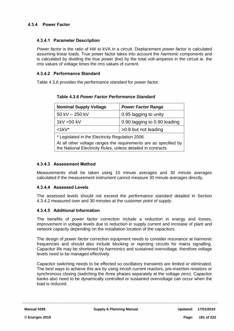
Manual 0295
Supply & Planning Manual
Updated:
17/01/2019 © Energex 2019
Page:
181 of 222
4.3.4 Power Factor
Parameter Description 4.3.4.1
Power factor is the ratio of kW to kVA in a circuit. Displacement power factor is calculated assuming linear loads. True power factor takes into account the harmonic components and is calculated by dividing the true power (kw) by the total volt-amperes in the circuit ie. the rms values of voltage times the rms values of current.
Performance Standard 4.3.4.2
Table 4.3.6 provides the performance standard for power factor.
Table 4.3.6 Power Factor Performance Standard
Nominal Supply Voltage Power Factor Range
50 kV – 250 kV 0.95 lagging to unity
1kV <50 kV 0.90 lagging to 0.90 leading
<1kV* >0.8 but not leading
* Legislated in the Electricity Regulation 2006.
At all other voltage ranges the requirements are as specified by the National Electricity Rules, unless detailed in contracts.
Assessment Method 4.3.4.3
Measurements shall be taken using 10 minute averages and 30 minute averages calculated if the measurement instrument cannot measure 30 minute averages directly.
Assessed Levels 4.3.4.4
The assessed levels should not exceed the performance standard detailed in Section 4.3.4.2 measured over and 30 minutes at the customer point of supply.
Additional Information 4.3.4.5
The benefits of power factor correction include a reduction in energy and losses, improvement in voltage levels due to reduction in supply current and increase of plant and network capacity depending on the installation location of the capacitors. The design of power factor correction equipment needs to consider resonance at harmonic frequencies and should also include blocking or rejecting circuits for mains signalling. Capacitor life may be shortened by harmonics and sustained overvoltage, therefore voltage levels need to be managed effectively. Capacitor switching needs to be effected so oscillatory transients are limited or eliminated. The best ways to achieve this are by using inrush current reactors, pre-insertion resistors or synchronous closing (switching the three phases separately at the voltage zero). Capacitor banks also need to be dynamically controlled or sustained overvoltage can occur when the load is reduced.
Manual 0295
Supply & Planning Manual
Updated:
17/01/2019 © Energex 2019
Page:
182 of 222
4.4 POWER QUALITY ASSESSMENT
4.4.1 Purpose
This section provides guidance on the approach to assessment of power quality impacts on the electrical network and customer installations.
4.4.2 Definitions
Power quality is a function of a wide range of electrical parameters. An ideal power quality would have:
voltage waveform which is purely sinusoidal
constant supply frequency of 50 Hz
equal peak voltages in each phase and of a fixed value
fixed angles of 120o between each phase
100% supply reliability
It is impossible to maintain such a supply with constantly changing system loads, exposure to equipment failure and to unforeseen external disturbances.
Energex defines power quality in terms of the degree to which the supply system is free from major distortions and fluctuations in supply voltage and frequency, and the number and duration of interruptions to supply (blackouts).
4.4.3 Load Categories Requiring Assessment
Sensitive Loads 4.4.3.1
Computers and other sensitive electronic equipment are now in wide use, and are very vulnerable to disturbances present on the supply system and within the customer's installation. This has brought power quality into sharper focus by the customer, as is now an important determinant of their satisfaction with Energex service.
Most voltage problems associated with computers and other sensitive equipment are not just related to just high or low steady state voltage levels, but to momentary voltage surges, sags or interruptions or to rapid changes in voltage (voltage fluctuation). The starting of a large motor for example, can result in voltage sag due to the high inrush current. A fault on a distribution line, even though cleared, can result in a momentary sag, surge or interruption. These momentary voltage disturbances may result from a wide variety of causes on the supply system or within a customer's own installation.
In the design of the distribution system every effort is taken to minimise the causes and effects of faults by careful construction, installation of protective equipment to speedily isolate and disconnect faulted equipment, and proper planned maintenance of the supply network. In spite of all these efforts faults cannot be totally avoided and many disturbances cannot be easily reduced to levels which do not affect sensitive equipment. The best solution is often for the customer to install special power protection equipment (after wiring and earthing systems have been checked for adequacy).
Problem History 4.4.3.2
It is important to find out if there is any history of problems at the customer's installation related to power quality. Ask the customer if he has any recorded problems and when
Manual 0295
Supply & Planning Manual
Updated:
17/01/2019 © Energex 2019
Page:
183 of 222
they occur (time date place equipment or process affected). This information can be used to check whether there is any correlation with recorded events on the Energex network. If the customer cannot be specific, ask the customer over what period of time problems have been occurring in order to help identify the problem source. If the problems have just started occurring, it could coincide with changes within the customer's own installation. For example, new equipment installed or changes in operating modes. In general the type of customer and the equipment employed may help to pinpoint problem areas.
It must be realised that most customers will not be aware of the cause of the problems; for instance, whether the problems are self inflicted from within their installation, or generated on the Energex network. They may only know that a piece of equipment has malfunctioned or tripped off, or only that a particular process has shutdown. It is therefore very important to listen to the symptoms described in order to make an accurate diagnosis.
In the event that the customer perceives a problem but is unable to supply any supporting evidence, ask the customer to set up a logging system to record the time, date, nature and frequency of problems. In a lot of cases some form if testing will be required.
Critical Processes 4.4.3.3
The customer usually has processes that are critical to their business. Ask the customer which processes if interrupted would have the biggest impact in terms of safety/damage, loss of production, downtime, and costs.
Type of Sensitive Equipment 4.4.3.4
Microprocessor-based controls and power electronics devices are sensitive to many types of disturbances besides actual interruptions. In addition, motor contactors and other devices held closed by a magnetic coil are also sensitive to disturbances, as well as protection equipment.
Because the most sensitive equipment is often the most critical to the customer's process, it is necessary to identify this equipment so that remedial measures can be investigated to desensitise it.
Power Protection Equipment 4.4.3.5
Power protection equipment is available to desensitise customer equipment from the effects of disturbances. Typically this includes four main categories, offering varying degrees of effectiveness:
power filters;
line or power conditioners;
standby power supplies; and
uninterruptible power supplies. The category of equipment being employed should be listed, along with the equipment and processes being protected. This will indicate any enhanced level of immunity to disturbances.
Manual 0295
Supply & Planning Manual
Updated:
17/01/2019 © Energex 2019
Page:
184 of 222
Impact of Process Interruption 4.4.3.6
The impact of disturbances on the customer’s overall operation may be anywhere from minor inconvenience through to equipment damage and costly production downtime. Obtaining a general indication of the impact will provide valuable information that may be used to develop cost effective solutions to desensitise the installation. This information will be very useful in both planning and design stages for new installations.
Automatic Restart Facility 4.4.3.7
It is important to know whether the plant will automatically restart after a shutdown. For instance restart facilities may reduce the impact of a disturbance by reducing downtime. However restart facilities may have an impact on the amount of load that can be satisfactorily restored due to protection settings, particularly if a lot of motors are all trying to start simultaneously.
Safety/Damage Issues 4.4.3.8
The effect on safety of personnel or damage to equipment resulting from an unplanned interruption of the customer’s process needs to be distinguished from economic loss due to lost or spoilt production and downtime. These issues are likely to strongly affect decisions made by the customer for emergency and standby power, and decisions made to improve the immunity of sensitive equipment to supply disturbances.
Emergency and Standby Power 4.4.3.9
The provision of emergency and standby power systems within the customer’s installation can reduce the impact of interruptions. An emergency system will normally be sized to supply critical loads, while a standby system will provide power to restore normal operation of the plant. Both systems rely on the provision of an independent alternative source, which upon failure of the normal source, can be switched across to supply load within a specified time period. There are three basic types usually installed within customer installations:
Engine-driven generators - diesel, petrol, gas
Turbine-driven generators - steam, gas/oil
Stored energy systems - mechanical, battery It is important to ascertain which type of system is being installed, its purpose, whether it is for emergency or standby supply, its capacity, its response time, and available service time. Note the type of system employed will have a large bearing on these parameters. In some cases the customer may prefer the emergency or standby power system to be provided by Energex. This would need to be discussed with the customer at the planning stage.
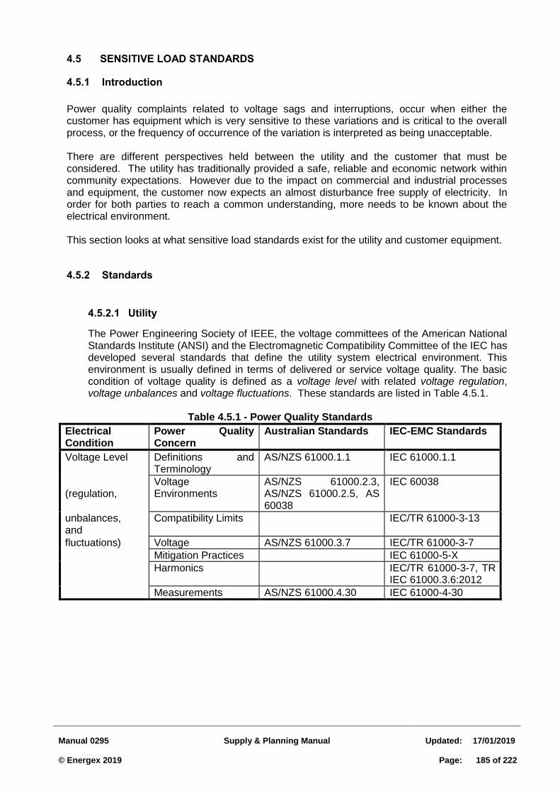
Manual 0295
Supply & Planning Manual
Updated:
17/01/2019 © Energex 2019
Page:
185 of 222
4.5 SENSITIVE LOAD STANDARDS
4.5.1 Introduction
Power quality complaints related to voltage sags and interruptions, occur when either the customer has equipment which is very sensitive to these variations and is critical to the overall process, or the frequency of occurrence of the variation is interpreted as being unacceptable.
There are different perspectives held between the utility and the customer that must be considered. The utility has traditionally provided a safe, reliable and economic network within community expectations. However due to the impact on commercial and industrial processes and equipment, the customer now expects an almost disturbance free supply of electricity. In order for both parties to reach a common understanding, more needs to be known about the electrical environment.
This section looks at what sensitive load standards exist for the utility and customer equipment.
4.5.2 Standards
Utility 4.5.2.1
The Power Engineering Society of IEEE, the voltage committees of the American National Standards Institute (ANSI) and the Electromagnetic Compatibility Committee of the IEC has developed several standards that define the utility system electrical environment. This environment is usually defined in terms of delivered or service voltage quality. The basic condition of voltage quality is defined as a voltage level with related voltage regulation, voltage unbalances and voltage fluctuations. These standards are listed in Table 4.5.1.
Table 4.5.1 - Power Quality Standards
Electrical Condition
Power Quality Concern
Australian Standards IEC-EMC Standards
Voltage Level Definitions and Terminology
AS/NZS 61000.1.1 IEC 61000.1.1
(regulation,
Voltage Environments
AS/NZS 61000.2.3, AS/NZS 61000.2.5, AS 60038
IEC 60038
unbalances, and
Compatibility Limits IEC/TR 61000-3-13
fluctuations) Voltage AS/NZS 61000.3.7 IEC/TR 61000-3-7
Mitigation Practices IEC 61000-5-X
Harmonics IEC/TR 61000-3-7, TR IEC 61000.3.6:2012
Measurements AS/NZS 61000.4.30 IEC 61000-4-30
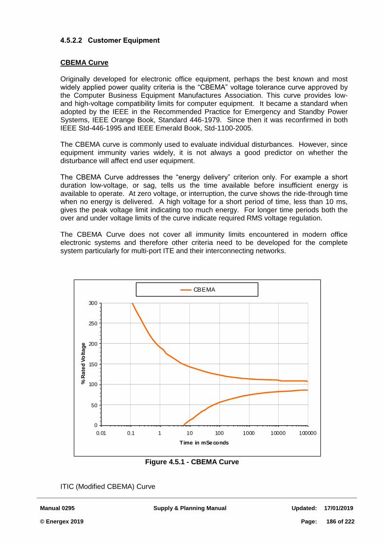
Manual 0295
Supply & Planning Manual
Updated:
17/01/2019 © Energex 2019
Page:
186 of 222
Customer Equipment 4.5.2.2
CBEMA Curve
Originally developed for electronic office equipment, perhaps the best known and most widely applied power quality criteria is the “CBEMA” voltage tolerance curve approved by the Computer Business Equipment Manufactures Association. This curve provides low- and high-voltage compatibility limits for computer equipment. It became a standard when adopted by the IEEE in the Recommended Practice for Emergency and Standby Power Systems, IEEE Orange Book, Standard 446-1979. Since then it was reconfirmed in both IEEE Std-446-1995 and IEEE Emerald Book, Std-1100-2005. The CBEMA curve is commonly used to evaluate individual disturbances. However, since equipment immunity varies widely, it is not always a good predictor on whether the disturbance will affect end user equipment. The CBEMA Curve addresses the “energy delivery” criterion only. For example a short duration low-voltage, or sag, tells us the time available before insufficient energy is available to operate. At zero voltage, or interruption, the curve shows the ride-through time when no energy is delivered. A high voltage for a short period of time, less than 10 ms, gives the peak voltage limit indicating too much energy. For longer time periods both the over and under voltage limits of the curve indicate required RMS voltage regulation. The CBEMA Curve does not cover all immunity limits encountered in modern office electronic systems and therefore other criteria need to be developed for the complete system particularly for multi-port ITE and their interconnecting networks.
Figure 4.5.1 - CBEMA Curve
ITIC (Modified CBEMA) Curve
0
50
100
150
200
250
300
0.01 0.1 1 10 100 1000 10000 100000
Time in mSe conds
% R
ate
d V
olt
ag
e
CBEMA
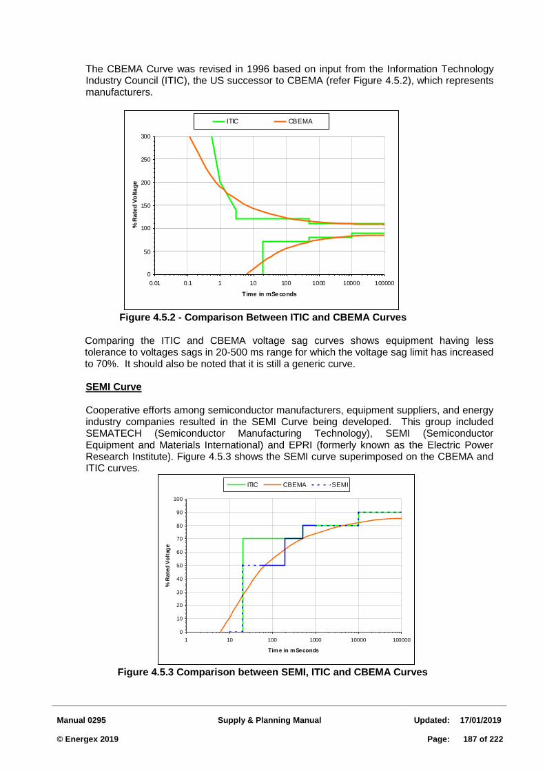
Manual 0295
Supply & Planning Manual
Updated:
17/01/2019 © Energex 2019
Page:
187 of 222
The CBEMA Curve was revised in 1996 based on input from the Information Technology Industry Council (ITIC), the US successor to CBEMA (refer Figure 4.5.2), which represents manufacturers.
Figure 4.5.2 - Comparison Between ITIC and CBEMA Curves
Comparing the ITIC and CBEMA voltage sag curves shows equipment having less tolerance to voltages sags in 20-500 ms range for which the voltage sag limit has increased to 70%. It should also be noted that it is still a generic curve.
SEMI Curve Cooperative efforts among semiconductor manufacturers, equipment suppliers, and energy industry companies resulted in the SEMI Curve being developed. This group included SEMATECH (Semiconductor Manufacturing Technology), SEMI (Semiconductor Equipment and Materials International) and EPRI (formerly known as the Electric Power Research Institute). Figure 4.5.3 shows the SEMI curve superimposed on the CBEMA and ITIC curves.
Figure 4.5.3 Comparison between SEMI, ITIC and CBEMA Curves
0
50
100
150
200
250
300
0.01 0.1 1 10 100 1000 10000 100000
Time in mSe conds
% R
ate
d V
olt
ag
e
ITIC CBEMA
0
10
20
30
40
50
60
70
80
90
100
1 10 100 1000 10000 100000
Tim e in m Seconds
% R
ate
d V
olt
age
ITIC CBEMA SEMI
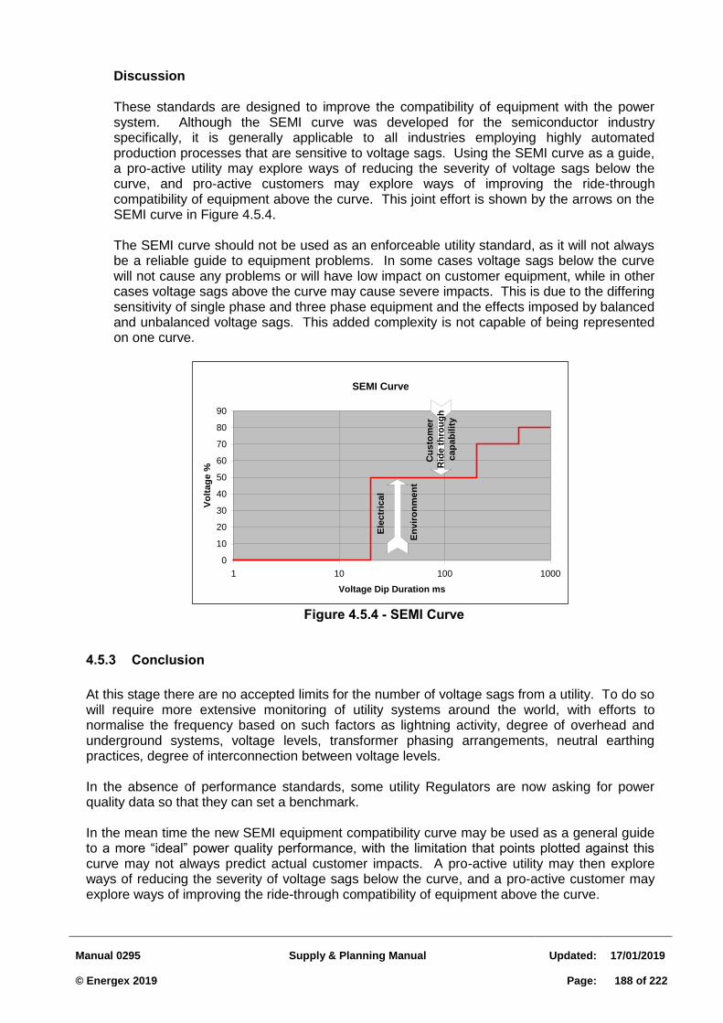
Manual 0295
Supply & Planning Manual
Updated:
17/01/2019 © Energex 2019
Page:
188 of 222
Discussion These standards are designed to improve the compatibility of equipment with the power system. Although the SEMI curve was developed for the semiconductor industry specifically, it is generally applicable to all industries employing highly automated production processes that are sensitive to voltage sags. Using the SEMI curve as a guide, a pro-active utility may explore ways of reducing the severity of voltage sags below the curve, and pro-active customers may explore ways of improving the ride-through compatibility of equipment above the curve. This joint effort is shown by the arrows on the SEMI curve in Figure 4.5.4. The SEMI curve should not be used as an enforceable utility standard, as it will not always be a reliable guide to equipment problems. In some cases voltage sags below the curve will not cause any problems or will have low impact on customer equipment, while in other cases voltage sags above the curve may cause severe impacts. This is due to the differing sensitivity of single phase and three phase equipment and the effects imposed by balanced and unbalanced voltage sags. This added complexity is not capable of being represented on one curve.
Figure 4.5.4 - SEMI Curve
4.5.3 Conclusion
At this stage there are no accepted limits for the number of voltage sags from a utility. To do so will require more extensive monitoring of utility systems around the world, with efforts to normalise the frequency based on such factors as lightning activity, degree of overhead and underground systems, voltage levels, transformer phasing arrangements, neutral earthing practices, degree of interconnection between voltage levels.
In the absence of performance standards, some utility Regulators are now asking for power quality data so that they can set a benchmark.
In the mean time the new SEMI equipment compatibility curve may be used as a general guide to a more “ideal” power quality performance, with the limitation that points plotted against this curve may not always predict actual customer impacts. A pro-active utility may then explore ways of reducing the severity of voltage sags below the curve, and a pro-active customer may explore ways of improving the ride-through compatibility of equipment above the curve.
SEMI Curve
0
10
20
30
40
50
60
70
80
90
1 10 100 1000
Voltage Dip Duration ms
Vo
ltag
e %
Cu
sto
mer
Rid
e t
hro
ug
h
cap
ab
ilit
y
Ele
ctr
ical
En
vir
on
men
t
Manual 0295
Supply & Planning Manual
Updated:
17/01/2019 © Energex 2019
Page:
189 of 222
4.6 SENSITIVE LOAD SOLUTIONS
4.6.1 Introduction
This sections describes general solutions to improve ride-through performance of sensitive customer equipment and processes. Sufficient detail is given to assist in any customer discussions, however further investigation would be required by the customer to establish the practicality of the potential solutions for their own facilities.
4.6.2 Approach
Voltage sags are not a concern unless they cause equipment to maloperate. This depends on the equipment sensitivity to disturbances (ride through characteristics). In a highly automated process a shutdown of a piece of equipment can cause a chain reaction that upsets the entire process. In particular, an uncontrolled shutdown can result in product loss, damaged equipment, safety hazards and opportunity costs.
Without very specific testing, it is not possible to pinpoint exact equipment and shutdown sequences, except at a very high level. However it is possible to discuss the main components of these plant systems and their sensitivity to voltage disturbances. It is at this component level that desensitising critical equipment needs to be addressed.
4.6.3 Hierarchy of Shutdown
For voltage disturbances where the voltage level is less than 90%, the first items to shutdown will be PLCs, microprocessors, variable speed drives. The second items to drop out will be contactors and relays from 50% to 75% within 1-2 cycles and switch mode power supplies for voltage sags below 50% for up to 300 ms. The third items will be motors with typical ride through for an interruption up to 0.5 seconds, however the impact on the process due to speed drop may be the limiting case.
4.6.4 Mitigation Techniques
Ride-through improvement techniques for control and protection circuits are now discussed.
Increase Steady State Voltage 4.6.4.1
Increasing the steady state voltage to critical equipment will increase the remaining voltage during voltage sags and help to improve ride-through performance.
Review Protection Settings 4.6.4.2
Undervoltage and unbalance relay settings on critical equipment should be reviewed to avoid inadvertent tripping during a voltage sag.
Modify/Replace Equipment DC Power Supplies 4.6.4.3
DC power supplies to critical sensitive equipment may be modified or replaced as follows:
Manual 0295
Supply & Planning Manual
Updated:
17/01/2019 © Energex 2019
Page:
190 of 222
For DC power supplies with an adjustable input voltage range, if possible choose a voltage range near the top of the range to allow more room for voltage sags.
Replace selected critical equipment power supplies with a universal power supply and connect the voltage phase to phase rather than phase to neutral. The chosen rating should be at least two times the expected load.
A three phase power supply properly designed and sized will effectively tolerate voltage sags on one or two phases that would shut down a single phase power supply.
Apply Selective Power Conditioning Equipment 4.6.4.4
Many voltage sag related shutdowns can be overcome when power conditioning devices are applied to critical control power supplies. The devices most applicable are:
Stored Energy Inverter (SEI): Otherwise known as Dip Proofing Inverters, provide an alternative source of power similar to a UPS except it uses capacitors instead of batteries for its stored energy.
Constant Voltage Transformer (CVT): The CVT (also called a ferroresonant transformer) is a device that maintains two separate magnetic paths with limited coupling between them. The output contains a parallel resonant tank circuit and draws power from the primary to replace power delivered to the load. The transformer is designed so that the resonant path is in saturation while the other is not. As a result a further change in primary voltage will not translate into changes in the saturated secondary voltage, and voltage regulation results. These devices need to be oversized to provide voltage sag ride-through performance.
Coil Hold-In Devices: Some manufacturers of power conditioners now provide a coil hold-in device to mitigate the effects of voltage sags on individual relays and contactors. Two commercial brands are the KnowTrip and the CoilLock.
The Uninterruptible Power Supply (UPS): The UPS can come in three basic types: standby, line interactive, and rectifier/charger. The standby UPS switches to battery and provides an inverter output to the load once the voltage sag is detected. The line interactive UPS is an online type that employs a regulating transformer (CVT) when the incoming voltage is normal. The rectifier/charger UPS is also an on line unit. The unit constantly rectifies the incoming AC line voltage. The resulting DC voltage is then used to charge the batteries and to feed the inverter circuit for the units output section.
UPSs are often chosen without much consideration of alternative power conditioning options. Once installed, this usually presents a problem if batteries are not properly maintained. CVTs are often favoured over UPSs when only voltage sag ride-through is required because they are relatively maintenance free, with no batteries to replace or moving parts to maintain and about half the cost of a UPS or SEI. The coil hold-in devices are relatively new and are an alternative to CVTs where individual contactors are targeted for improvement. The SEI are relatively new and have the advantage that a capacitor for energy storage rather than a battery is used, thereby minimising maintenance. The main application of these devices is to provide a limited amount of ride-through (several seconds) to allow the orderly shutdown of processes. Sufficient space must be available to install the devices.
4.6.5 Application of Mitigation Techniques
Manual 0295
Supply & Planning Manual
Updated:
17/01/2019 © Energex 2019
Page:
191 of 222
The application of mitigation techniques to the specific requirements of PLCs, VSDs and motor control circuits are now discussed.
Programmable Logic Controllers (PLC) 4.6.5.1
The PLC is a vital component of the process control system (sequencing and logic functions), and should be prevented from shutting down during a voltage sag so that it can continue to monitor and analyse the process and provide data to determine the causes of a shutdown. A CVT will provide ride-through for the majority of voltage sags experienced. However to provide protection against an interruption to supply, a UPS is required. Delays may also be built into the PLC logic so that it does not respond immediately to certain PLC inputs controlling motors and VSDs, providing safety is not compromised.
Variable Speed Drives 4.6.5.2
Because VSD sensitivity is mainly due to under voltage protection settings, it is important to check with the drive manufacturer that they are appropriate for the drive voltage rating and that settings have been correctly applied rather than just default settings. In some cases there may be scope to lower the setting. The VSD name plate voltage should always be matched as closely as possible to the nominal input voltage by use of interposing transformers if necessary. Where some compromise is necessary in matching voltages, it is preferable to bias it towards the upper end of its voltage range.
A ride-through module offered as an add-on feature by most VSD manufacturers may be able to be purchased and retrofitted to existing drives. It works by monitoring the DC bus voltage and during a voltage sag switches on at a preset level and boosts the remaining line voltage on the capacitor to maintain it above the trip level. However it does not store energy and cannot therefore provide total protection against interruptions or voltage sags below about 40% of nominal voltage.
Most VSDs cannot restart after tripping until the motor comes to a complete stop. To overcome this problem some manufacturers incorporate a feature called synchronous “flying restart”. This feature allows connection before the motor has a chance to significantly slow down and affect the process. The drive manufacturer should be consulted to determine if this feature is available. This type of application is suited to Clean Rooms.
Motor Control Circuits 4.6.5.3
There are two main control scheme modifications that are used to improve the ride-through performance of motor control circuits. The first method relies on automatic reclosure of the motor after it has been tripped by the motor contactor, and the second on delayed drop-out of the motor. Delayed drop-out is preferred if the process can tolerate some reduction in motor speed and torque output for a brief period (say up to 0.5 seconds). Several delayed drop-out schemes are presented:
DC Contactor: This scheme requires the control circuitry to be modified to supply a DC contactor instead of an AC contactor. Coil magnetisation throughout the voltage sag is provided from a low resistance path around the coil which tends to prolong the collapsing magnetic field. DC coils also have the advantage of a lower drop-out voltage and longer ride-through time than equivalent AC coils. The slow decay of the magnetic field strength holds the contacts closed until the control circuit is opened or the magnetic field strength becomes small enough to allow the contactor to drop out. A capacitor resistor network can be placed in parallel with the coil to supplement the energy for ride-through.
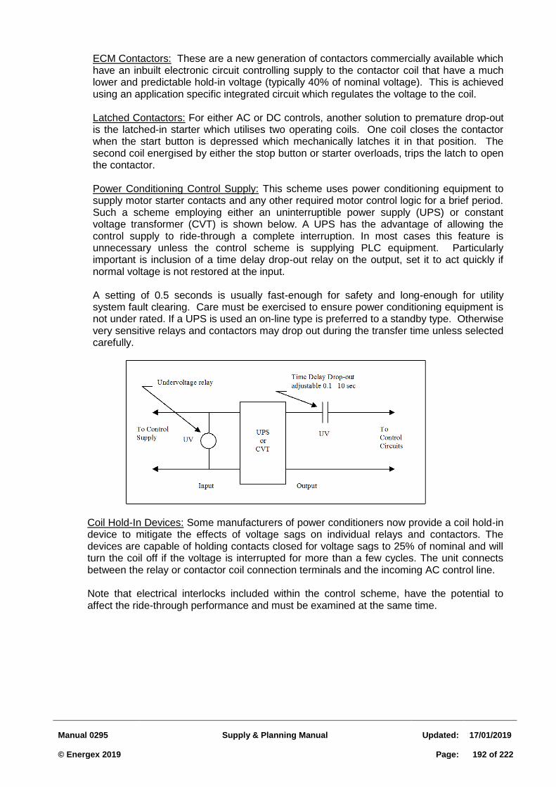
Manual 0295
Supply & Planning Manual
Updated:
17/01/2019 © Energex 2019
Page:
192 of 222
ECM Contactors: These are a new generation of contactors commercially available which have an inbuilt electronic circuit controlling supply to the contactor coil that have a much lower and predictable hold-in voltage (typically 40% of nominal voltage). This is achieved using an application specific integrated circuit which regulates the voltage to the coil.
Latched Contactors: For either AC or DC controls, another solution to premature drop-out is the latched-in starter which utilises two operating coils. One coil closes the contactor when the start button is depressed which mechanically latches it in that position. The second coil energised by either the stop button or starter overloads, trips the latch to open the contactor.
Power Conditioning Control Supply: This scheme uses power conditioning equipment to supply motor starter contacts and any other required motor control logic for a brief period. Such a scheme employing either an uninterruptible power supply (UPS) or constant voltage transformer (CVT) is shown below. A UPS has the advantage of allowing the control supply to ride-through a complete interruption. In most cases this feature is unnecessary unless the control scheme is supplying PLC equipment. Particularly important is inclusion of a time delay drop-out relay on the output, set it to act quickly if normal voltage is not restored at the input.
A setting of 0.5 seconds is usually fast-enough for safety and long-enough for utility system fault clearing. Care must be exercised to ensure power conditioning equipment is not under rated. If a UPS is used an on-line type is preferred to a standby type. Otherwise very sensitive relays and contactors may drop out during the transfer time unless selected carefully.
Coil Hold-In Devices: Some manufacturers of power conditioners now provide a coil hold-in device to mitigate the effects of voltage sags on individual relays and contactors. The devices are capable of holding contacts closed for voltage sags to 25% of nominal and will turn the coil off if the voltage is interrupted for more than a few cycles. The unit connects between the relay or contactor coil connection terminals and the incoming AC control line. Note that electrical interlocks included within the control scheme, have the potential to affect the ride-through performance and must be examined at the same time.
Manual 0295
Supply & Planning Manual
Updated:
17/01/2019 © Energex 2019
Page:
193 of 222
4.6.6 Recommended Solutions
The best engineering approach is to apply solutions in a controlled manner and to evaluate the results before proceeding with wholesale changes. The following recommendations are subject to detailed investigations by the customers in consultation with equipment manufacturers/suppliers.
Boosting Steady State Voltage: Investigate the boosting of steady state voltage to the facility and individual equipment. Make appropriate adjustments. Protection Review: Carry out undervoltage and unbalance protection review of critical equipment to voltage sags. Make appropriate adjustments.
DC Power Supplies: On selected critical equipment, trial the installation of a universal DC power supply with input voltage range (eg. 85V to 264V AC ). Connect input voltages phase to phase rather than phase to neutral..
PLCs: On all critical PLCs install standby UPSs. On selected less critical PLCs, where 1sec ride-through would allow sufficient time for an orderly shutdown of processes, carry out a trial installation of four Energy Stored Inverters. Careful attention to sizing, installation and maintenance requirements should be considered.
VSDs: Carry out a trial installation of four constant voltage transformers fitted to the control/logic power supply of selected VSDs. An evaluation against unprotected VSDs of similar size should be carried out over a suitable time period. Synchronous flying restart be investigated in consultation with the drive manufacturer. The retrofitting of a DC booster module be investigated.
Motor Control Circuits:
(1) Carry out a trial installation of constant voltage transformers fitted to a number of critical
motor control circuits. Units should be sized to replace existing control supply transformers. Evaluation against unprotected similar motor control circuits should be carried out over a suitable time period.
(2) Carry out a trial installation of hold-in coil devices fitted to a number of critical motor control circuits. Evaluation against unprotected similar motor control circuits should be carried out over a suitable time period.
4.6.7 “Custom Power” Technology
The emergence of higher power rated solid state devices, has created the possibility for improving customer power quality in “larger lumps” without the need to de-sensitise the many pieces of critical equipment. De-sensitising equipment, although cost effective for low power consumption equipment and control circuits, may still not yield sufficient improvement. Two such technologies are the Dynamic Voltage Restorer (DVR) and the Dynamic Uninterruptible Power Supply (DUPS). In the case of the DVR, protection is offered against voltage sags only, while the DUPS offers protection against complete power loss, but is more efficient than conventional UPS systems.
Manual 0295
Supply & Planning Manual
Updated:
17/01/2019 © Energex 2019
Page:
194 of 222
4.6.8 Conclusions
Mitigation techniques are available to reduce the sensitivity of critical equipment. The focus should be on PLCs/controllers, VSDs and motor control circuits since they are the most sensitive components. Power conditioning at the process control level is an effective method of improving ride-through, however it does require assistance from manufacturers/suppliers of the critical equipment.
The practicality of the techniques proposed are subject to further detailed investigation by the customer. It is strongly recommended that a project is established by the customer to do this work. Implementation should commence in the suggested critical areas in a staged manner.
The application of “custom power” technology is an alternative solutions path that has only become a reality in recent years due to advances in high voltage, high power solid state devices. This technology is particularly attractive for customers who have little or no knowledge of critical equipment sensitivities and cannot afford to take equipment out of production to make small scale improvements.
Manual 0295
Supply & Planning Manual
Updated:
17/01/2019 © Energex 2019
Page:
195 of 222
4.7 DISTURBING LOADS ASSESSMENT: HARMONICS
4.7.1 Introduction
Harmonics generated by a particular customer can interfere with the operation of network equipment, and other customer loads. Customer equipment is the main cause of network distortion levels, and must be controlled to maintain satisfactory levels.
Harmonic distortion is produced by any non-linear load connected to the network. The most common and increasing cause of this distortion is the use of electronic power converters to supply and control loads. Manufacturers are required to comply with harmonic standards for smaller household domestic appliances, and are not normally the subject of Energex interest. However larger industrial applications have the potential to impact power quality to a large number of customers, depending on the location, and size of the equipment. DC motors and variable speed AC drives are very common sources.
Before permission is given to connect such equipment, it is necessary to assess whether the distortion level is within acceptable limits at the point of common coupling (PCC), which is the point in the network electrically nearest to where other customers are, or may be, supplied. This assessment must take full account of options available to supply the installation, including contingency conditions, future configuration, and presence of shunt capacitor banks at the zone substation.
For larger installations, it is strongly recommended that the customer engage a consultant to ensure harmonic levels are satisfactory within the installation. Energex would normally supply network impedance, loading and configuration details upon request. The consultant is encouraged to perform the calculations for the PCC also, for review by Energex.
Customers wishing to connect harmonic producing load are normally only permitted to contribute quantities specified and calculated by methods in TR IEC 61000.3.7:2012 “Electromagnetic compatibility (EMC)-Limits - Assessment of emission limits for the connection of fluctuating installations to MV, HV and EHV power systems” In some cases restrictions will be placed on the type, size, design and operation of equipment able to be connected. Alternatively or in combination with, the network arrangement must be chosen appropriately. In most cases, the customer will be expected to contribute to any additional costs incurred on the network to reduce harmonic levels.
4.7.2 What are Harmonics?
By design, the waveform of an A.C. supply system delivered by a generator to a linear load is largely sinusoidal, with minimal distortion. A linear load is one in which the load current and voltage across the load have the same waveform. Significant distortion can occur in the generator ac waveform when non-linear loads are connected.
Nonlinear devices produce non-sinusoidal current waveforms when energised with a sinusoidal voltage. Nearly all of these devices on power systems are shunt elements, the bulk of which are loads. In a normal power system the loads are a mixture of linear and non-linear devices. Purely resistive heating loads are as close to the ideal linear load as is practical, with motors reasonably linear depending on the level of saturation achieved in the magnetic circuit. Electronic power converter loads made up of rectifiers and/or inverters are non-linear, as well as ferromagnetic (transformers) and arcing devices.
Although transformers are numerous, they produce distortions of only about 1% of their name plate load rating. Arcing devices and electronic power converters can produce distortions of 20-
Manual 0295
Supply & Planning Manual
Updated:
17/01/2019 © Energex 2019
Page:
196 of 222
30% of rating are and therefore the primary concern, particularly as the latter is projected to increase in use significantly in the future.
The distortion in the ac waveshape can be mathematically viewed as a mixture of pure sinusoidal shapes of higher frequencies which are an integral “n-th” multiple of the 50 Hz fundamental frequency.
4.7.3 Harmonic Analysis
The magnitude of harmonic currents and voltages at any point in a distribution system can be predicted using accepted harmonic modelling techniques that consider the frequency dependence of circuit components and loads. In the majority of cases, non-linear devices or harmonic sources may be considered a constant current source independently injected into the system at the point of generation, at each harmonic independently. The overall response of the network is then assessed in terms of individual harmonic values or the total harmonic distortion.
Harmonic analysis can be performed using hand calculations, but is much simplified using the network modelling package (e.g. PSSU or SINCAL).
Guidance on the assessment of industrial equipment harmonic sources is contained in TR IEC 61000.3.7:2012 “Electromagnetic compatibility (EMC)-Limits - Assessment of emission limits for the
connection of fluctuating installations to MV, HV and EHV power systems”. Particular reference needs to be taken on how to combine the network response to multiple harmonic sources and the use of diversity factors for converter equipment.
4.7.4 Harmonic Measurement
Before a large distorting load is connected to a distribution system a harmonic analysis will usually be carried out to ensure harmonic distortion is within the limits. This will also be accompanied by before and after measurements at the point of common coupling to check background levels pre-existing before connection of the new load, and compliance with limits imposed following connection. In a distribution system, the background readings may be high due to other distorting loads connected to the network and may vary considerably over time due to differing load duty cycles, system configuration and load level, and resonant conditions.
4.7.5 Harmonic Guidelines – Variable Speed Drives
It should be noted that installation guidelines found in Australian Standard AS/NZS 61000.3.6 are based on dc motor drive circuits or electronic circuits which have an inductive filter on the dc side. However this standard does not deal with ac drives which have a rectifier and inverter combination - the dc side of which will often only consist of a capacitive filter.
Drive Rating in Relation to Supply Capacity 4.7.5.1
The most important single factor in assessing whether an ac drive will cause unacceptable voltage harmonics in the supply is the drive rating in relation to the supply capacity. Supply capacity is usually measured by the "Fault Level" which is the three phase product of open circuit voltage and (hypothetical) short circuit current. The fault level is the main parameter of the supply system used in protection calculations. It is usually measured in kVA or MV.A. In a city or large town the fault level of the 400 V supply is typically 10 to 20 MVA, while in country regions it may be only 2 MVA. Fault level is a measure of the series impedance of the supply.
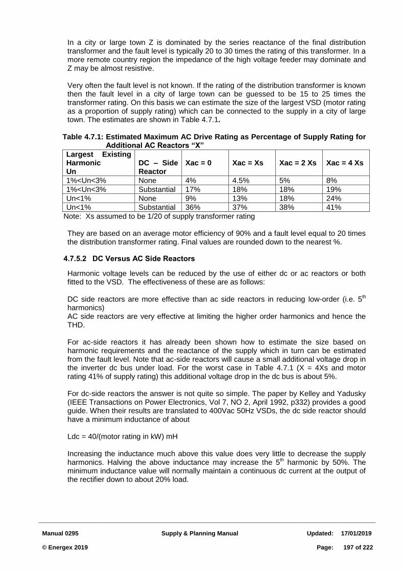
Manual 0295
Supply & Planning Manual
Updated:
17/01/2019 © Energex 2019
Page:
197 of 222
In a city or large town Z is dominated by the series reactance of the final distribution transformer and the fault level is typically 20 to 30 times the rating of this transformer. In a more remote country region the impedance of the high voltage feeder may dominate and Z may be almost resistive.
Very often the fault level is not known. If the rating of the distribution transformer is known then the fault level in a city of large town can be guessed to be 15 to 25 times the transformer rating. On this basis we can estimate the size of the largest VSD (motor rating as a proportion of supply rating) which can be connected to the supply in a city of large town. The estimates are shown in Table 4.7.1.
Table 4.7.1: Estimated Maximum AC Drive Rating as Percentage of Supply Rating for
Additional AC Reactors “X”
Largest Existing Harmonic Un
DC – Side Reactor
Xac = 0
Xac = Xs
Xac = 2 Xs
Xac = 4 Xs
1%<Un<3% None 4% 4.5% 5% 8%
1%<Un<3% Substantial 17% 18% 18% 19%
Un<1% None 9% 13% 18% 24%
Un<1% Substantial 36% 37% 38% 41%
Note: Xs assumed to be 1/20 of supply transformer rating
They are based on an average motor efficiency of 90% and a fault level equal to 20 times the distribution transformer rating. Final values are rounded down to the nearest %.
DC Versus AC Side Reactors 4.7.5.2
Harmonic voltage levels can be reduced by the use of either dc or ac reactors or both fitted to the VSD. The effectiveness of these are as follows:
DC side reactors are more effective than ac side reactors in reducing low-order (i.e. 5th harmonics) AC side reactors are very effective at limiting the higher order harmonics and hence the THD.
For ac-side reactors it has already been shown how to estimate the size based on harmonic requirements and the reactance of the supply which in turn can be estimated from the fault level. Note that ac-side reactors will cause a small additional voltage drop in the inverter dc bus under load. For the worst case in Table 4.7.1 (X = 4Xs and motor rating 41% of supply rating) this additional voltage drop in the dc bus is about 5%.
For dc-side reactors the answer is not quite so simple. The paper by Kelley and Yadusky (IEEE Transactions on Power Electronics, Vol 7, NO 2, April 1992, p332) provides a good guide. When their results are translated to 400Vac 50Hz VSDs, the dc side reactor should have a minimum inductance of about
Ldc = 40/(motor rating in kW) mH
Increasing the inductance much above this value does very little to decrease the supply harmonics. Halving the above inductance may increase the 5th harmonic by 50%. The minimum inductance value will normally maintain a continuous dc current at the output of the rectifier down to about 20% load.

Manual 0295
Supply & Planning Manual
Updated:
17/01/2019 © Energex 2019
Page:
198 of 222
What about Multiple Drives and Load Diversity? 4.7.5.3
Because the structure of the input circuit is virtually standard, harmonics from multiple ac drives will not tend to add algebraically. It is important to estimate the largest simultaneous load on multiple VSDs in order to assess harmonic performance. A single VSD with rating equal to this largest simultaneous load should give almost identical harmonics to those produced by the multiple drives.
The Effect on Power Factor 4.7.5.4
The Power Factor (PF) of a balanced three-phase load is commonly defined by:
PF = Real Power ./ ( 3 Vrms . I rms) Harmonics in the ac line current tend to increase the rms line current without contributing to real power. Where harmonic currents are large, cable and transformer sizes may need to be increased.
If substantial dc-side reactors are fitted the Power Factor of an ac drive is close to 0.95. If however neither dc-side nor ac-side reactors are fitted the harmonic currents are much larger and the power factor is significantly lower. However the effect on the power factor of the overall supply is generally quite small because ac drives usually make up only a small proportion of the total load.
This section is concerned with the impact of starting motors on the quality of supply on the network. The most significant effect is voltage change, also referred to as voltage fluctuation, which may cause annoying flicker of incandescent lamps. The severity of the flicker and hence it’s offensiveness to customers, is determined by the magnitude and frequency of the voltage change. This section discusses the quality of supply limits applicable, methods for reducing voltage change during starting, and the programs available for calculating voltage change.
Manual 0295
Supply & Planning Manual
Updated:
17/01/2019 © Energex 2019
Page:
199 of 222
4.8 DISTURBING LOADS ASSESSMENT: MOTOR STARTING
4.8.1 Introduction
This section is concerned with the impact of starting motors on the quality of supply on the network. The most significant effect is voltage change, also referred to as voltage fluctuation, which may cause annoying flicker of incandescent lamps. The severity of the flicker and hence it’s offensiveness to customers, is determined by the magnitude and frequency of the voltage change. This section discusses the quality of supply limits applicable, methods for reducing voltage change during starting, and the programs available for calculating voltage change.
4.8.2 Allowable Voltage Change during Motor Starting
When an induction motor is started direct on line (DOL) the current required to develop starting torque may be 6 to 7 times full load current when nominal voltage is applied at the motor terminals. The power factor of the initial starting current is quite low (0.2 to 0.4 lagging). Therefore a high initial reactive load is taken from the supply system, gradually reducing as the speed of the machine approaches a steady state value.
The resulting voltage fluctuation may cause interference to other customers’ supply due to excessive lamp flicker or mal-operation of certain voltage sensitive equipment, depending on the magnitude and frequency of the voltage change. In addition motor performance may be adversely affected due to insufficient accelerating torque.
The maximum allowable voltage fluctuation on the supply system is detailed in TR IEC
61000.3.7:2012.
4.8.3 Motor Connection Guidelines
The following guidelines should be considered before approval is given for the connection of a motor.
For motors started less than 4 times per day, the relative voltage change at the PCC should not exceed 6%. For motors started more frequently, refer to Table 6 of TR IEC 61000.3.7:2012. This Table shows the allowable voltage change for different rates of occurrence of voltage changes. The voltage at the customer’s motor contactor should not drop below approximately 0.8 per unit (346.4 V on a 433 V base) to ensure that the “hold in” coil does not open during starting conditions. The actual “drop out” voltage may be used if available. The voltage at the motor terminals should provide sufficient starting torque for the motor load application. Since the starting torque is proportional to the square of the motor terminal voltage, the minimum terminal voltage may be determined for a given motor load application. Although this is the responsibility of the customer, typical average values of required motor starting torque for different motor load applications are given in Table 4.8.1 for reference.
In the absence of motor supplier data, the starting torque for various induction motor types may be calculated using the starting efficiency values provided in Table 4.8.2 for a given starting current.
Manual 0295
Supply & Planning Manual
Updated:
17/01/2019 © Energex 2019
Page:
200 of 222
4.8.4 Methods for Reducing Voltage Change during Motor Starting
There are two main methods for reducing unacceptable voltage fluctuations at the PCC as follows:
Limit starting current by use of a motor starter to reduce the voltage at the motor terminals. Reduce the supply system source impedance (ie increase the fault level).
LV Motors during Starting: 4.8.4.1
The motor must be started in such a manner that the rms starting current does not exceed the following limits for more than 0.02 sec (1 cycle):
45 amps in the case of single phase 230 V motors;
53 + 3.3 k amps in the case of 400 V motors, where k is the continuous output rating in kilowatts of the largest motor in the installation; e.g. 300 amps for a 75 kW motor.
Conditions (a) and (b) may be relaxed for any motor which is not started frequently and is less than 10% of the total customer's motor load connected to the one service, or if the premises are fed directly from a substation or via other appropriate supply conditions.
4.8.5 Use of Motor Starters
There are two main reasons for using motor starters:
1. To limit the starting current and therefore the relative voltage change at the motor
terminals, motor starting contactor and the point of common coupling with the network in accordance with Energex quality of supply standards;
2. To reduce the starting torque of the motor and thereby control acceleration of the motor load. This is the responsibility of the customer.
Table 4.8.3 lists typical starting currents and torques for common methods of starting squirrel cage induction motors (for wound rotor induction motors, secondary resistance starters may be used). Where permissible, direct on line (DOL) starting is chosen due to its simplicity and low cost. If DOL starting is precluded due to either of the above reasons, then use of an alternative starting method should be considered (i.e. star/delta, autotransformer, primary resistor, and soft starter).
The choice of starting method often depends on the relative cost and the particular motor application (e.g. motor/load torque-speed compatibility).
The most common methods are based on reduced voltage starting and may therefore suffer from reduced starting torque. As a consequence, if the load torque requirements exceed the available reduced starting torque, the motor will fail to accelerate to its rated speed. The motor will then continue to draw a large magnitude of current, and may be damaged due to overheating if a protective device fails to operate.
There are two methods of transition from start to run mode (excluding Solid State starters which provide stepless reduced voltage starting):
Manual 0295
Supply & Planning Manual
Updated:
17/01/2019 © Energex 2019
Page:
201 of 222
Closed circuit transition where the motor remains connected to the supply during the transition period; Open circuit transition where the motor is disconnected from the supply during the transition period. This produces a higher current surge than closed circuit transition and may cause excessive shaft impact torques. For this reason this method is not favoured.
The motor must accelerate to at least 90% of full speed before switching from start to run mode. Switching before this speed will result in a current surge during the transition period equal or greater than the DOL value. In this case the motor is effectively being started DOL. This situation may occur if the starter is incorrectly matched to the motor load torque requirements and/or if insufficient acceleration time is allowed.
Brief details are given on each of the motor starters:
Star Delta 4.8.5.1
The Star-Delta starter requires all six ends of the starter to be brought out to the motor terminal box. This method reduces the DOL starting current by one third and also avoids the high torque at about 80% speed, which may be undesirable for certain applications. However the resulting starting torque is one third of the normal starting torque which corresponds to approximately 60% of full load torque (assuming typical normal starting torque of 180% of full load torque). Both closed and open transition starting is employed.
Autotransformer 4.8.5.2
The autotransformer starter allows increased starting torque over the Star-Delta starter with selection of either the 80% or 65% taps. Lower starting current and torque is possible with a 50% tap, but would not be economic over a primary resistor method. The autotransformer is not cost effective for use with standard squirrel cage motors for light duty, but is often the best choice for medium and heavy duty applications. Both closed and open transition starting is employed.
Primary Resistor 4.8.5.3
Although a primary resistor of appropriate size can limit the starting current to the same value as an autotransformer, less accelerating torque is available as the motor runs up to speed due to the higher voltage drop across the resistor. The pull out torque is approximately equal to full load torque at 90% of full speed compared to 150% of full load torque for an autotransformer (or primary reactor). This method may not therefore be practical for large motor applications.
Solid State Motor Starter 4.8.5.4
The solid state motor starter, (or commonly known as a soft starter) usually consists of six silicon controlled rectifiers (SCRs) between the power supply and the motor. Phase angle control of the gating pulses to the SCRs allows the voltage at the motor terminals to be fully controlled during the start process with full voltage applied after the starting period. (A) Timed Ramp Mode: This technique applies a ramped voltage output to the motor to provide an almost linear speed versus time characteristic during the start-up period. The ramp time is adjustable and will depend on the load. The voltage is usually ramped from an initial 30% to 60% of rated voltage to provide sufficient initial torque. A ramp down time may also be included during the stop sequence (for particular applications). This mode of operation is commonly used for heavy friction loads.
Manual 0295
Supply & Planning Manual
Updated:
17/01/2019 © Energex 2019
Page:
202 of 222
(B) Current Limit Mode: In current limiting mode the motor voltage is adjusted to maintain the current below a preset level. Typically the level can be adjusted between 300 to 400% of motor full load current. If the current limit is set too low, insufficient torque may be available for the particular motor/load application. This mode of operation is commonly used for both light and heavy inertia loads, or where restrictions have been placed on the starting current by the Supply Authority (refer Table 4.8.4 for common motor applications).
4.8.6 Reduction of Source Impedance
To reduce the voltage fluctuations at the PCC an alternative to limiting starting current, or in combination with, is to reduce the source impedance upstream. Possible methods include:
shifting the PCC by building a dedicated feeder or part feeder
shifting the PCC by dedicating a separate transformer at a zone substation to supply the motor load feeder
shifting the PCC by supplying the customer from their own distribution substation
re-conductoring a portion of the feeder with “heavier” conductor
paralleling zone substation transformers, eg. 33/11kV
Other options such as a series capacitor are capable of reducing voltage fluctuation but require more specialised application and would need to be referred to Network Investigations Department for consideration.
The most appropriate method will depend on the particular situation. Such factors as the capacity of the supply system, the size of the motor(s) to be connected, system losses, limitations imposed on the motor starting current, and the rate of return on investment may influence the decision. The supply arrangements should be fully discussed with the customer or their consultant to ensure that a co-ordinated overall design is achieved.
4.8.7 Motor Starting Calculations
Motor starting calculations are routinely carried out to quantify the voltage change on the network to ensure it remains within accepted quality of supply limits, and determine if the proposed supply arrangements are adequate to start the motor(s). The following methods/programs are available to carry out the calculations: Hand calculations based on network impedance data and motor details; MOTORCAL: Motor starting program for quick assessment of motors up to 100 kW in size located under Distribution Planning intranet site; PSS/U & DINIS: Power system analysis packages incorporating loadflow, fault studies and motor starting; these programs should be used for detailed studies involving motors exceeding 100 kW in size which may be supplied from a dedicated transformer.
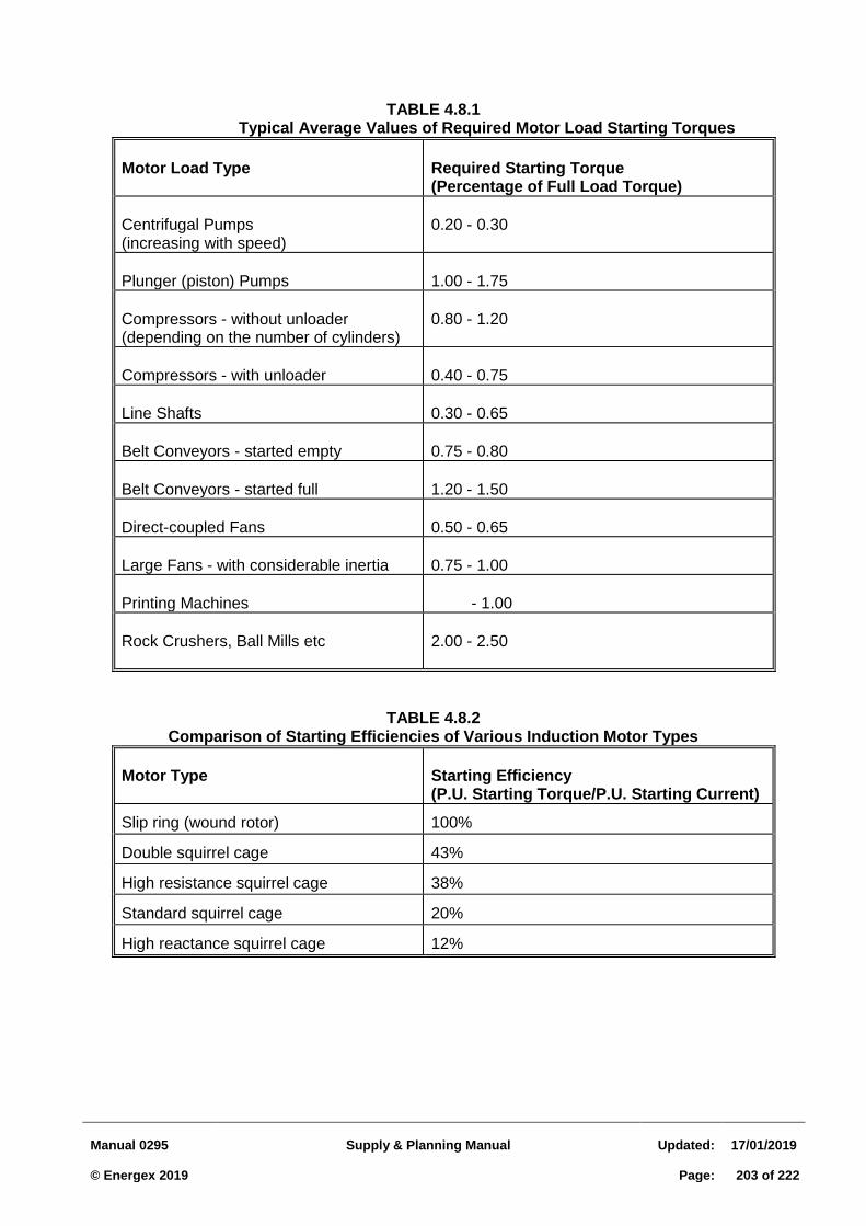
Manual 0295
Supply & Planning Manual
Updated:
17/01/2019 © Energex 2019
Page:
203 of 222
TABLE 4.8.1
Typical Average Values of Required Motor Load Starting Torques
Motor Load Type
Required Starting Torque (Percentage of Full Load Torque)
Centrifugal Pumps (increasing with speed)
0.20 - 0.30
Plunger (piston) Pumps
1.00 - 1.75
Compressors - without unloader (depending on the number of cylinders)
0.80 - 1.20
Compressors - with unloader
0.40 - 0.75
Line Shafts
0.30 - 0.65
Belt Conveyors - started empty
0.75 - 0.80
Belt Conveyors - started full
1.20 - 1.50
Direct-coupled Fans
0.50 - 0.65
Large Fans - with considerable inertia
0.75 - 1.00
Printing Machines
- 1.00
Rock Crushers, Ball Mills etc
2.00 - 2.50
TABLE 4.8.2 Comparison of Starting Efficiencies of Various Induction Motor Types
Motor Type Starting Efficiency (P.U. Starting Torque/P.U. Starting Current)
Slip ring (wound rotor) 100%
Double squirrel cage 43%
High resistance squirrel cage 38%
Standard squirrel cage 20%
High reactance squirrel cage 12%
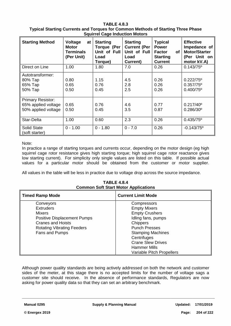
Manual 0295
Supply & Planning Manual
Updated:
17/01/2019 © Energex 2019
Page:
204 of 222
TABLE 4.8.3 Typical Starting Currents and Torques for Common Methods of Starting Three Phase
Squirrel Cage Induction Motors
Starting Method Voltage at Motor Terminals (Per Unit)
Starting Torque (Per Unit of Full Load Torque)
Starting Current (Per Unit of Full Load Current)
Typical Power Factor of Starting Current
Effective Impedance of Motor/Starter (Per Unit on motor kV.A)
Direct on Line 1.00 1.80 7.0 0.26 0.143/75º
Autotransformer: 80% Tap 65% Tap 50% Tap
0.80 0.65 0.50
1.15 0.76 0.45
4.5 2.8 2.5
0.26 0.26 0.26
0.222/75º 0.357/75º 0.400/75º
Primary Resistor: 65% applied voltage 50% applied voltage
0.65 0.50
0.76 0.45
4.6 3.5
0.77 0.87
0.217/40º 0.286/30º
Star-Delta 1.00 0.60 2.3 0.26 0.435/75º
Solid State (soft starter)
0 - 1.00 0 - 1.80 0 - 7.0 0.26 -0.143/75º
Note: In practice a range of starting torques and currents occur, depending on the motor design (eg high squirrel cage rotor resistance gives high starting torque; high squirrel cage rotor reactance gives low starting current). For simplicity only single values are listed on this table. If possible actual values for a particular motor should be obtained from the customer or motor supplier. All values in the table will be less in practice due to voltage drop across the source impedance.
TABLE 4.8.4 Common Soft Start Motor Applications
Timed Ramp Mode Current Limit Mode
Conveyors Extruders Mixers Positive Displacement Pumps Cranes and Hoists Rotating Vibrating Feeders Fans and Pumps
Compressors Empty Mixers Empty Crushers Idling fans, pumps Chippers Punch Presses Stamping Machines Centrifuges Crane Slew Drives Hammer Mills Variable Pitch Propellers
Although power quality standards are being actively addressed on both the network and customer sides of the meter, at this stage there is no accepted limits for the number of voltage sags a customer site should receive. In the absence of performance standards, Regulators are now asking for power quality data so that they can set an arbitrary benchmark.
Manual 0295
Supply & Planning Manual
Updated:
17/01/2019 © Energex 2019
Page:
205 of 222
In order to be able to benchmark network performance and respond to specific customer concerns about voltage sags received at a particular site, monitoring equipment needs to be installed. The location and extent of this monitoring is a key issue that needs to be addressed in cooperation with interested parties such as the Regulator and the ESAA. In order to make such decisions it is important to understand the way voltage sags are reflected throughout the network and their likely severity. This addendum report explores the pattern of voltages which occur and proposes a new index for characterising severity.
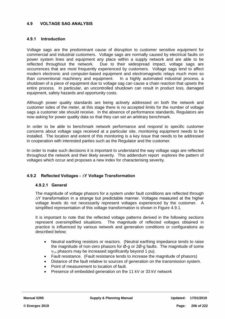
Manual 0295
Supply & Planning Manual
Updated:
17/01/2019 © Energex 2019
Page:
206 of 222
4.9 VOLTAGE SAG ANALYSIS
4.9.1 Introduction
Voltage sags are the predominant cause of disruption to customer sensitive equipment for commercial and industrial customers. Voltage sags are normally caused by electrical faults on power system lines and equipment any place within a supply network and are able to be reflected throughout the network. Due to their widespread impact, voltage sags are occurrences that are most frequently experienced by customers. Voltage sags tend to affect modern electronic and computer-based equipment and electromagnetic relays much more so than conventional machinery and equipment. In a highly automated industrial process, a shutdown of a piece of equipment due to voltage sag can cause a chain reaction that upsets the entire process. In particular, an uncontrolled shutdown can result in product loss, damaged equipment, safety hazards and opportunity costs.
Although power quality standards are being actively addressed on both the network and customer sides of the meter, at this stage there is no accepted limits for the number of voltage sags a customer site should receive. In the absence of performance standards, Regulators are now asking for power quality data so that they can set an arbitrary benchmark.
In order to be able to benchmark network performance and respond to specific customer concerns about voltage sags received at a particular site, monitoring equipment needs to be installed. The location and extent of this monitoring is a key issue that needs to be addressed in cooperation with interested parties such as the Regulator and the customer.
In order to make such decisions it is important to understand the way voltage sags are reflected throughout the network and their likely severity. This addendum report explores the pattern of voltages which occur and proposes a new index for characterising severity.
4.9.2 Reflected Voltages - ∆Y Voltage Transformation
General 4.9.2.1
The magnitude of voltage phasors for a system under fault conditions are reflected through ∆Y transformation in a strange but predictable manner. Voltages measured at the higher voltage levels do not necessarily represent voltages experienced by the customer. A simplified representation of this voltage transformation is shown in Figure 4.9.1. It is important to note that the reflected voltage patterns derived in the following sections represent oversimplified situations. The magnitude of reflected voltages obtained in practice is influenced by various network and generation conditions or configurations as described below;
Neutral earthing resistors or reactors. (Neutral earthing impedance tends to raise the magnitude of non-zero phasors for Ø-g or 2Ø-g faults. The magnitude of some VLN phasors may be increased significantly beyond 1 pu).
Fault resistance. (Fault resistance tends to increase the magnitude of phasors)
Distance of the fault relative to sources of generation on the transmission system.
Point of measurement to location of fault.
Presence of embedded generation on the 11 kV or 33 kV network
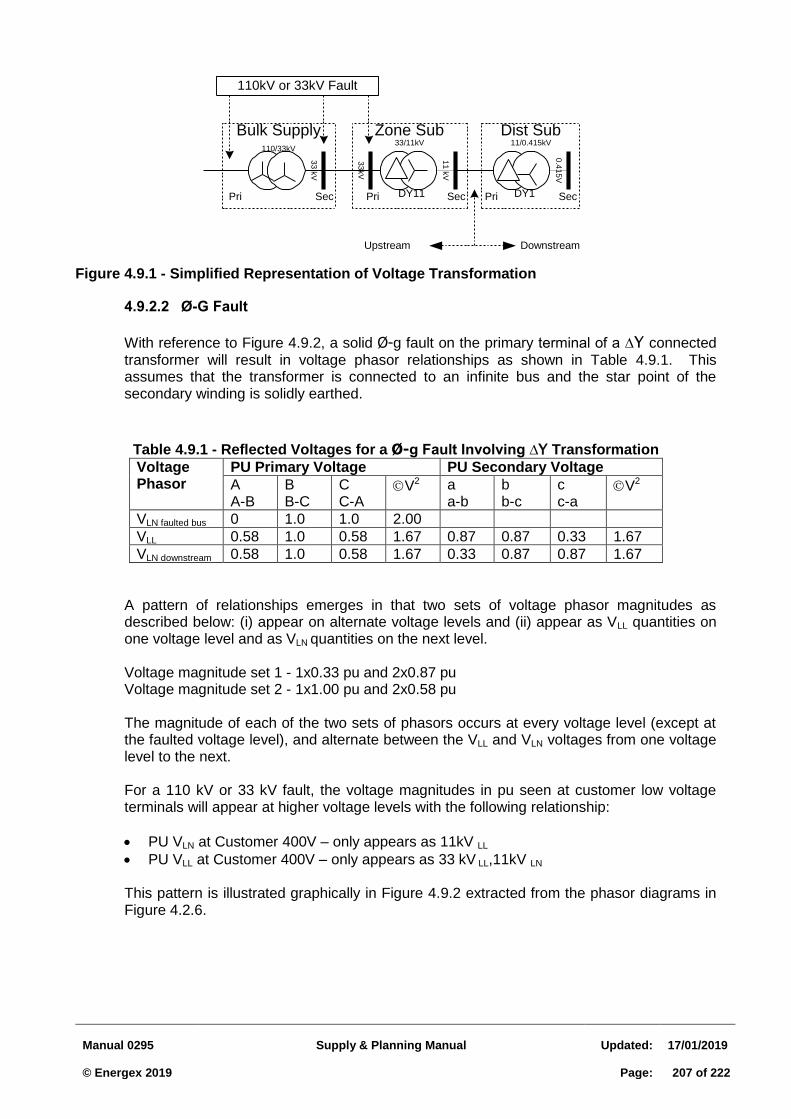
Manual 0295
Supply & Planning Manual
Updated:
17/01/2019 © Energex 2019
Page:
207 of 222
Figure 4.9.1 - Simplified Representation of Voltage Transformation
Ø-G Fault 4.9.2.2
With reference to Figure 4.9.2, a solid Ø-g fault on the primary terminal of a ∆Y connected transformer will result in voltage phasor relationships as shown in Table 4.9.1. This assumes that the transformer is connected to an infinite bus and the star point of the secondary winding is solidly earthed.
Table 4.9.1 - Reflected Voltages for a Ø-g Fault Involving ∆Y Transformation
Voltage Phasor
PU Primary Voltage PU Secondary Voltage
A A-B
B B-C
C C-A
V2 a a-b
b b-c
c c-a
V2
VLN faulted bus 0 1.0 1.0 2.00
VLL 0.58 1.0 0.58 1.67 0.87 0.87 0.33 1.67
VLN downstream 0.58 1.0 0.58 1.67 0.33 0.87 0.87 1.67
A pattern of relationships emerges in that two sets of voltage phasor magnitudes as described below: (i) appear on alternate voltage levels and (ii) appear as VLL quantities on one voltage level and as VLN quantities on the next level. Voltage magnitude set 1 - 1x0.33 pu and 2x0.87 pu Voltage magnitude set 2 - 1x1.00 pu and 2x0.58 pu The magnitude of each of the two sets of phasors occurs at every voltage level (except at the faulted voltage level), and alternate between the VLL and VLN voltages from one voltage level to the next. For a 110 kV or 33 kV fault, the voltage magnitudes in pu seen at customer low voltage terminals will appear at higher voltage levels with the following relationship:
PU VLN at Customer 400V – only appears as 11kV LL
PU VLL at Customer 400V – only appears as 33 kV LL,11kV LN This pattern is illustrated graphically in Figure 4.9.2 extracted from the phasor diagrams in Figure 4.2.6.
Bulk Supply110/33kV
33
kV
Dist Sub11/0.415kV
Zone Sub33/11kV
11
kV
33
kV
0.4
15
V
PriSec PriPri Sec Sec
Upstream Downstream
110kV or 33kV Fault
DY1DY11
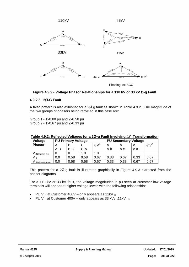
Manual 0295
Supply & Planning Manual
Updated:
17/01/2019 © Energex 2019
Page:
208 of 222
Figure 4.9.2 - Voltage Phasor Relationships for a 110 kV or 33 kV Ø-g Fault
2Ø-G Fault 4.9.2.3
A fixed pattern is also exhibited for a 2Ø-g fault as shown in Table 4.9.2. The magnitude of the two groups of phasors being recycled in this case are: Group 1 - 1x0.00 pu and 2x0.58 pu Group 2 - 1x0.67 pu and 2x0.33 pu
Table 4.9.2: Reflected Voltages for a 2Ø-g Fault Involving ∆Y Transformation
Voltage Phasor
PU Primary Voltage PU Secondary Voltage
A A-B
B B-C
C C-A
V2 a a-b
b b-c
c c-a
V2
VLN faulted bus 0 0 1.0 1.0
VLL 0.0 0.58 0.58 0.67 0.33 0.67 0.33 0.67
VLN downstream 0.0 0.58 0.58 0.67 0.33 0.33 0.67 0.67
This pattern for a 2Ø-g fault is illustrated graphically in Figure 4.9.3 extracted from the phasor diagrams. For a 110 kV or 33 kV fault, the voltage magnitudes in pu seen at customer low voltage terminals will appear at higher voltage levels with the following relationship:
PU VLN at Customer 400V – only appears as 11kV LL
PU VLL at Customer 400V – only appears as 33 kV LL,11kV LN
110kV
33kV
Vab=0.58puVca=0.58pu
a
c bVbc=1pu
Vc=1pu Vb=1pu
Va=0pu
Vab=0.58puVca=0.58pu
A
C BVbc=1pu
Vc=1pu Vb=1pu
Va=0pu
11kV
Vb=1pu
Vbc=0.87pu
Vab=0.87puVa=0.58
Vc=0.58Vca
=0
.33
pu
A
B
C
415V
Vca=0.58pu Vab=0.58pu
Vbc=1 pu
a
bc
Vb=0.87puVc=0.87pu
Va
=0
.33
pu
(c)(b)
Phasing: ex BCC
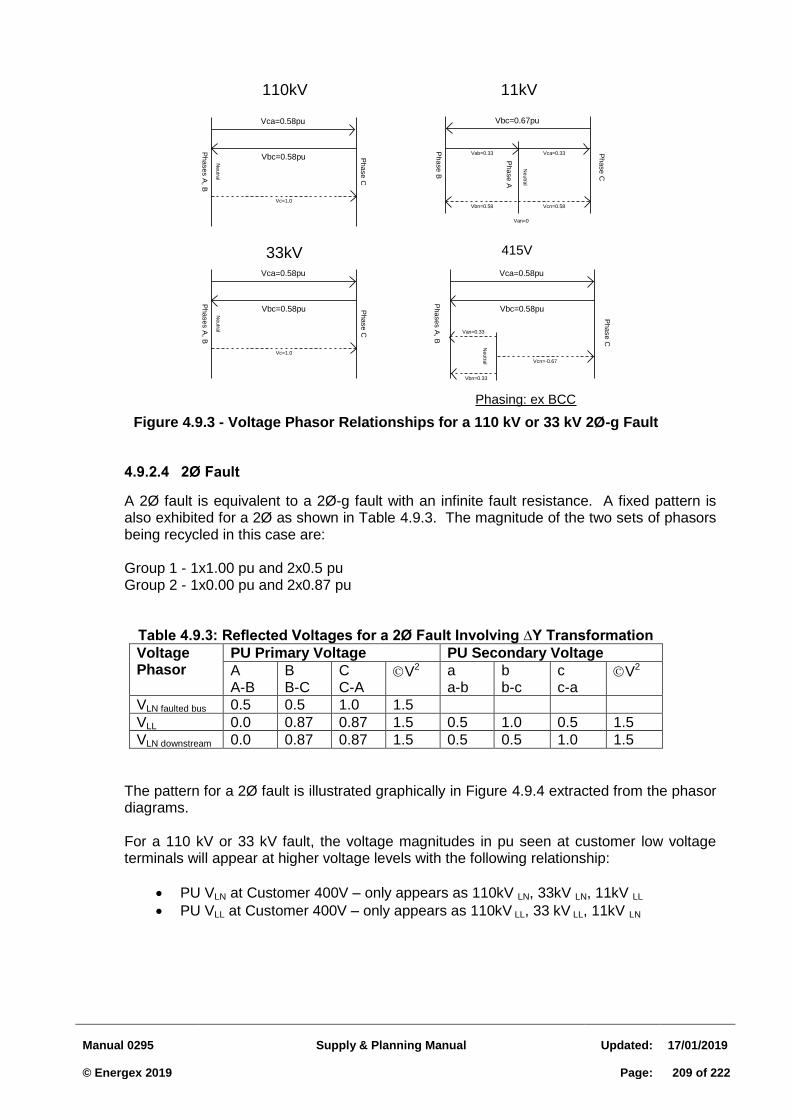
Manual 0295
Supply & Planning Manual
Updated:
17/01/2019 © Energex 2019
Page:
209 of 222
Figure 4.9.3 - Voltage Phasor Relationships for a 110 kV or 33 kV 2Ø-g Fault
2Ø Fault 4.9.2.4
A 2Ø fault is equivalent to a 2Ø-g fault with an infinite fault resistance. A fixed pattern is also exhibited for a 2Ø as shown in Table 4.9.3. The magnitude of the two sets of phasors being recycled in this case are: Group 1 - 1x1.00 pu and 2x0.5 pu Group 2 - 1x0.00 pu and 2x0.87 pu
Table 4.9.3: Reflected Voltages for a 2Ø Fault Involving ∆Y Transformation
Voltage Phasor
PU Primary Voltage PU Secondary Voltage
A A-B
B B-C
C C-A
V2 a a-b
b b-c
c c-a
V2
VLN faulted bus 0.5 0.5 1.0 1.5
VLL 0.0 0.87 0.87 1.5 0.5 1.0 0.5 1.5
VLN downstream 0.0 0.87 0.87 1.5 0.5 0.5 1.0 1.5
The pattern for a 2Ø fault is illustrated graphically in Figure 4.9.4 extracted from the phasor diagrams. For a 110 kV or 33 kV fault, the voltage magnitudes in pu seen at customer low voltage terminals will appear at higher voltage levels with the following relationship:
PU VLN at Customer 400V – only appears as 110kV LN, 33kV LN, 11kV LL
PU VLL at Customer 400V – only appears as 110kV LL, 33 kV LL, 11kV LN
110kV 11kV
Vca=0.58pu
Vbc=0.58pu Phase C
Neutra
l
Phases A
, B
Vc=1.0
Vbc=0.67pu
Phase A
Phase B
Neutra
l
Phase C
Vbn=0.58 Vcn=0.58
Vab=0.33 Vca=0.33
Van=0
33kV 415V
Vca=0.58pu
Vbc=0.58pu Phase C
Neutra
l
Phases A
, B
Vc=1.0
Vca=0.58pu
Vbc=0.58pu
Phases A
, B
Phase C
Neutra
l Vcn=-0.67
Vbn=0.33
Van=0.33
Phasing: ex BCC
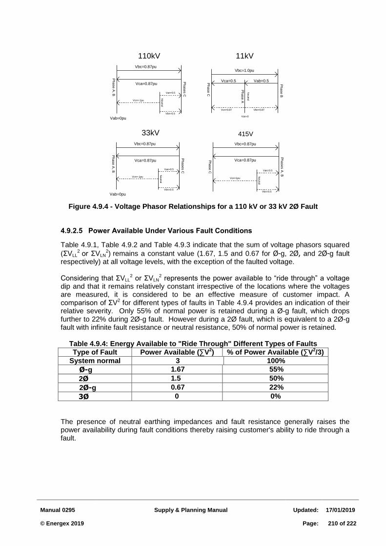
Manual 0295
Supply & Planning Manual
Updated:
17/01/2019 © Energex 2019
Page:
210 of 222
Figure 4.9.4 - Voltage Phasor Relationships for a 110 kV or 33 kV 2Ø Fault
Power Available Under Various Fault Conditions 4.9.2.5
Table 4.9.1, Table 4.9.2 and Table 4.9.3 indicate that the sum of voltage phasors squared
(ΣVLL2 or ΣVLN
2) remains a constant value (1.67, 1.5 and 0.67 for Ø-g, 2Ø, and 2Ø-g fault respectively) at all voltage levels, with the exception of the faulted voltage. Considering that ΣVLL
2 or ΣVLN2 represents the power available to “ride through” a voltage
dip and that it remains relatively constant irrespective of the locations where the voltages are measured, it is considered to be an effective measure of customer impact. A comparison of ΣV2 for different types of faults in Table 4.9.4 provides an indication of their relative severity. Only 55% of normal power is retained during a Ø-g fault, which drops further to 22% during 2Ø-g fault. However during a 2Ø fault, which is equivalent to a 2Ø-g fault with infinite fault resistance or neutral resistance, 50% of normal power is retained.
Table 4.9.4: Energy Available to "Ride Through" Different Types of Faults
Type of Fault Power Available (∑V2) % of Power Available (∑V2/3)
System normal 3 100%
Ø-g 1.67 55%
2Ø 1.5 50%
2Ø-g 0.67 22%
3Ø 0 0%
The presence of neutral earthing impedances and fault resistance generally raises the power availability during fault conditions thereby raising customer's ability to ride through a fault.
110kV 11kV
Vbc=0.87pu
Vca=0.87pu
Phases C
Phase A
, B
Neutra
l
Vcn=-1pu
Van=0.5
Vbn=0.5
Vab=0pu
Vbc=0.87pu
Vca=0.87pu
Phases C
Phase A
, B
Neutra
l
Vcn=-1pu
Van=0.5
Vbn=0.5
Vab=0pu
33kV 415V
Vbc=1.0pu
Phase B
Phase C
Neutra
l
Phase A
Vcn=0.87 Vbn=0.87
Vca=0.5 Vab=0.5
Van=0
Vbc=0.87pu
Vca=0.87pu
Phases A
, B
Phase C
Neutra
l
Vcn=1pu
Van=0.5
Vbn=0.5
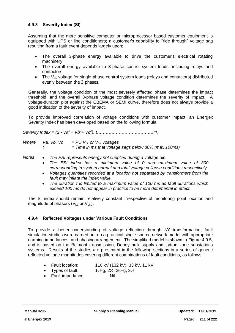
Manual 0295
Supply & Planning Manual
Updated:
17/01/2019 © Energex 2019
Page:
211 of 222
4.9.3 Severity Index (SI)
Assuming that the more sensitive computer or microprocessor based customer equipment is equipped with UPS or line conditioners; a customer's capability to “ride through” voltage sag resulting from a fault event depends largely upon:
The overall 3-phase energy available to drive the customer's electrical rotating machinery.
The overall energy available to 3-phase control system loads, including relays and contactors.
The VLN voltage for single-phase control system loads (relays and contactors) distributed
evenly between the 3 phases.
Generally, the voltage condition of the most severely affected phase determines the impact threshold, and the overall 3-phase voltage condition determines the severity of impact. A voltage-duration plot against the CBEMA or SEMI curve, therefore does not always provide a good indication of the severity of impact.
To provide improved correlation of voltage conditions with customer impact, an Energex Severity Index has been developed based on the following formula.
Severity Index = (3 - Va2 + Vb2+ Vc2). t…………………………………(1) Where Va, Vb, Vc = PU VLL or VLN voltages
t = Time in ms that voltage sags below 80% (max 100ms)
Notes The ESI represents energy not supplied during a voltage dip.
The ESI index has a minimum value of 0 and maximum value of 300 corresponding to system normal and total voltage collapse conditions respectively
Voltages quantities recorded at a location not separated by transformers from the fault may inflate the index value.
The duration t is limited to a maximum value of 100 ms as fault durations which exceed 100 ms do not appear in practice to be more detrimental in effect.
The SI index should remain relatively constant irrespective of monitoring point location and magnitude of phasors (VLL or VLN).
4.9.4 Reflected Voltages under Various Fault Conditions
To provide a better understanding of voltage reflection through Y transformation, fault simulation studies were carried out on a practical single-source network model with appropriate earthing impedances, and phasing arrangement. The simplified model is shown in Figure 4.9.5, and is based on the Belmont transmission, Doboy bulk supply and Lytton zone substations systems. Results of the studies are presented in the following sections in a series of generic reflected voltage magnitudes covering different combinations of fault conditions, as follows:
Fault location: 110 kV (132 kV), 33 kV, 11 kV
Types of fault: 1-g, 2, 2-g, 3
Fault impedance: Nil
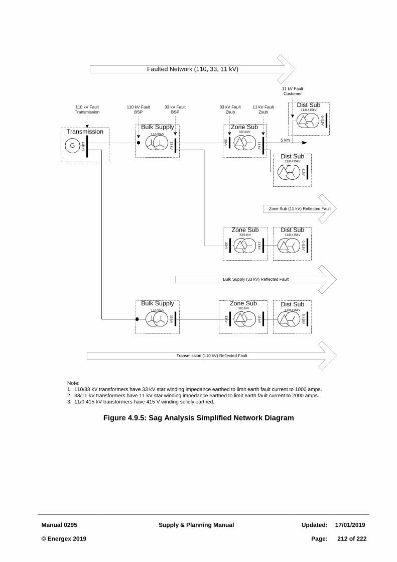
Manual 0295
Supply & Planning Manual
Updated:
17/01/2019 © Energex 2019
Page:
212 of 222
Figure 4.9.5: Sag Analysis Simplified Network Diagram
Faulted Network (110, 33, 11 kV)
Transmission
Dist Sub11/0.415kV
Dist Sub11/0.415kV
Dist Sub11/0.415kV
Dist Sub11/0.415kV
Zone Sub33/11kV
Bulk Supply110/33kV
Bulk Supply110/33kV
Zone Sub33/11kV
Zone Sub33/11kV
33
kV
11
kV
11
0 k
V
0.4
15
V
5 km1
1 k
V
33
kV
11
kV
0.4
15
V
33
kV
33
kV
41
5V
0.4
15
V
G
33
kV
Bulk Supply (33 kV) Reflected Fault
Transmission (110 kV) Reflected Fault
Zone Sub (11 kV) Reflected Fault
110 kV Fault
BSP
33 kV Fault
Zsub
11 kV Fault
Zsub
33 kV Fault
BSP
11 kV Fault
Customer
110 kV Fault
Transmission
Note:
1. 110/33 kV transformers have 33 kV star winding impedance earthed to limit earth fault current to 1000 amps.
2. 33/11 kV transformers have 11 kV star winding impedance earthed to limit earth fault current to 2000 amps.
3. 11/0.415 kV transformers have 415 V winding solidly earthed.
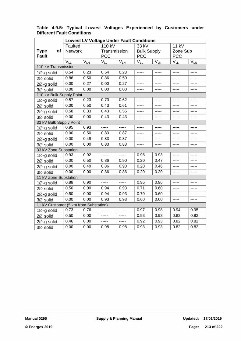
Manual 0295
Supply & Planning Manual
Updated:
17/01/2019 © Energex 2019
Page:
213 of 222
Table 4.9.5: Typical Lowest Voltages Experienced by Customers under Different Fault Conditions
Type of Fault
Lowest LV Voltage Under Fault Conditions
Faulted Network
110 kV Transmission PCC
33 kV Bulk Supply PCC
11 kV Zone Sub PCC
VLL VLN VLL VLN VLL VLN VLL VLN
110 kV Transmission
1-g solid 0.54 0.23 0.54 0.23 ----- ----- ----- -----
2 solid 0.86 0.50 0.86 0.50 ----- ----- ----- -----
2-g solid 0.00 0.27 0.00 0.27 ----- ----- ----- -----
3 solid 0.00 0.00 0.00 0.00 ----- ----- ----- -----
110 kV Bulk Supply Point
1-g solid 0.57 0.23 0.73 0.62 ----- ----- ----- -----
2 solid 0.00 0.50 0.43 0.61 ----- ----- ----- -----
2-g solid 0.58 0.33 0.43 0.55 ----- ----- ----- -----
3 solid 0.00 0.00 0.43 0.43 ----- ----- ----- -----
33 kV Bulk Supply Point
1-g solid 0.95 0.93 ----- ----- ----- ----- ----- -----
2 solid 0.00 0.50 0.83 0.87 ----- ----- ----- -----
2-g solid 0.00 0.49 0.83 0.87 ----- ----- ----- -----
3 solid 0.00 0.00 0.83 0.83 ----- ----- ----- -----
33 kV Zone Substation
1-g solid 0.93 0.92 ----- ----- 0.95 0.93 ----- -----
2 solid 0.00 0.50 0.86 0.90 0.20 0.47 ----- -----
2-g solid 0.00 0.49 0.86 0.90 0.20 0.46 ----- -----
3 solid 0.00 0.00 0.86 0.86 0.20 0.20 ----- -----
11 kV Zone Substation
1-g solid 0.88 0.90 ----- ----- 0.95 0.96 ----- -----
2 solid 0.50 0.00 0.94 0.93 0.71 0.60 ----- -----
2-g solid 0.50 0.00 0.94 0.93 0.70 0.60 ----- -----
3 solid 0.00 0.00 0.93 0.93 0.60 0.60 ----- -----
11 kV Customer (5 km from Substation)
1-g solid 0.73 0.76 ----- ----- 0.97 0.98 0.94 0.95
2 solid 0.50 0.00 ----- ----- 0.93 0.93 0.82 0.82
2-g solid 0.46 0.00 ----- ----- 0.92 0.93 0.82 0.82
3 solid 0.00 0.00 0.98 0.98 0.93 0.93 0.82 0.82
Manual 0295
Supply & Planning Manual
Updated:
17/01/2019 © Energex 2019
Page:
214 of 222
5 Appendix 5.1.A – Brisbane Central Business District Map
Refer to Section 3.2.5 - for substations to be installed in the Brisbane CBD area, the borders of which align with Brisbane City Council’s City Plan 2014 Mapping. The following map shows the boundaries
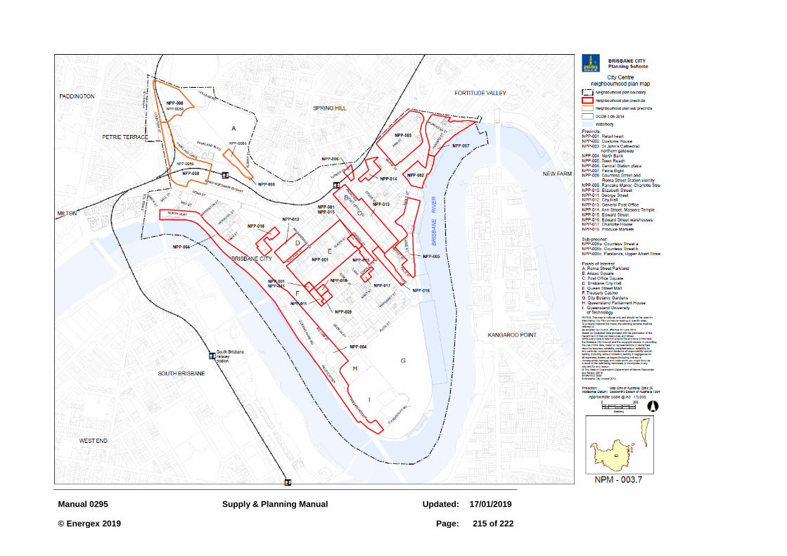
Manual 0295
Supply & Planning Manual
Updated:
17/01/2019 © Energex 2019
Page:
215 of 222
Manual 0295
Supply & Planning Manual
Updated:
17/01/2019 © Energex 2019
Page:
216 of 222
6 Amendment Record
17/01/2019 Version 6.0 Major amendments
References to 415/240V changed to 400/230V throughout the document
References to 240 ±6% changed to 230 +10%, -6% throughout the document
Section 2.7.6 now refers to the QEMM
Section 3.2.6 dual padmount arrangement added
Section 3.3.2 updated to reflect new 230V regulations
Section 3.3.2.2 Clarification note added to Table 3.3.1.
Section 3.3.2.3 Updated to include Transformer Monitors as well as MDIs
Section 3.3.3 Updated to reflect latest legislation. o Preferred voltage range added. o Voltage values updated throughout the section o Figs 3.3.7 and 3.3.8 updated with revised values o Table 3.3.4 updated o Table 3.3.5 updated
Section 3.3.4 Manual references updated
Section 3.3.4.2 minor revision
Section 3.3.4.3 o Distribution Transformer Tap Settings section updated o Table 3.3.7 updated to show both no load and max load recommended terminal
voltages o Remove reference to 30% PV penetration (outdated) o Remove refence to constant power mode (no longer allowed) o Added Power Quality Mode to comply with latest EG standards.
Section 3.3.5 o Revised clauses DES to DER and remove “high penetration” reference o Clarify reference to 25% as the transformer name plate rating
Section 3.6.5: o Recommended no load voltage range updated o References to QECMM revised to QECM and QEMM o Revised part a, b, e to make it consistent with latest EG standards
Section 4.2.2.2 updated to reference new legislation amendment and values
Section 4.2.2.4 updated
Section 4.2.2.5 updated
Section 4.2.3.5 updated to reference revised clause number in QECM
Improved readability – fixed layouts, general formatting, tables, spacing and titles. 01/08/2017 Version 4.2 General nomenclature and formatting changes throughout the document to represent current corporate branding standards. Major amendments
Section 2.3.4 “Asset Removal or Supply Abolishment Involving Substation Assets on Customer Premises” added
Manual 0295
Supply & Planning Manual
Updated:
17/01/2019 © Energex 2019
Page:
217 of 222
Section 2.5 now refers to RED 00982 - Subdivision Standards - Developer Design and Construct Estates
Section 2.7.6 now refers to the QECMM
Section 2.13.1 “Provision of Ground Transformer Stations” updated
Section 2.13.7(d) “Minimum Design Standards – Overhead Mains Extensions” updated
Section 2.14 now refers to RED 01143 - JW Connection Standard Small Scale Parallel Inverter Energy Systems up to 30 kVA
Section 3.2.5 “Establishing Distribution Substations On Customers' Premises” updated
Appendix 3.2A “Methods of Estimating Maximum Demand” updated
Section 3.3.2.3 “After Diversity Maximum Demand (ADMD)” ADMD values updated
Section 3.6.1 (e) added to the “Low Voltage Services” section
Section 3.6.5 “PV and BESS” added
Appendix 5.1.A “Brisbane Central Business District Map” now refers to Section 3.2.5 07/10/2015 Version 4.1 Major amendments Section 2.12.1.5 Alterations to Existing Works Due to Change in Land Use
Added “Responsibility for Recovery Costs” in Heading
In dot point (e) Demolition Works, added clause – “This arrangement does not apply for temporary building supply or where there are commercial contracts for the recovery of the electrical equipment and associated cables.
Section 2.15.2 Powerline Undergrounding and Re-engineering Programs
Incorporate all other clauses which were in BMS3364 Section 2.6.1.3 Joint Use Layout/Conduit Arrangements
Included guidelines for the number of conduits in various footpath locations Section 3.3 Low Voltage System Design and Planning
Revised section 01 Mar 2013 Version 4.0 Major amendments
Section 2.2 National Energy Customer Framework
Added new Section 2.2 on the National Energy Customer Framework
Added new Section 2.2.1 on Large Customer Connection Process
Section 2.4.2 Procedure for Supply to Customer Extensions
Added Network Service Centre request form (F2018)
Manual 0295
Supply & Planning Manual
Updated:
17/01/2019 © Energex 2019
Page:
218 of 222
Added new clause for Large Customer Connection process
Section 2.5.2 Responsibilities
Changed role from Subdivision and Streetlight Coordinator to Subdivision and Network Service Centre Manager
Section 2.14.3 Major Types of Private Generators
Added clause noting the Energex Standard for Small to Medium Scale Embedded Generators
Section 2.15.2 Powerline Undergrounding and Re-engineering Programs
Updated section to align with BMS 3364.
Section 2.16 FOOTPATH JOINT USE COST SHARING ARRANGEMENT
Updated cost sharing arrangements in accordance with BMS 3364.
Section 3.2.1 SUPPLY TO LARGE INSTALLATIONS – Introduction
Added reference to BMS 3544 & RED 00768 in last paragraph.
Updated planning/design process flowchart to replace “Letter of offer” by “Network Connection Contract”
Section 3.2.2 Application For Supply
Added “can be made via the Electrical Partners Portal on the Energex website or by phoning” & “significant lead times (i.e. 9 months)” to first paragraph.
Added “Network Connection Application F1201 signed and returned” to last paragraph.
Section 3.2.4 Methods Of Supplying Load From The Network
Added “or above the maximum statutory limit” to dot point (iii)
Added dot point (viii) – “Will the LV conductor length exceed the protective length of the distribution transformer fuse?”
Section 3.2.5 Establishing Distribution Substations On Customers' Premises
Added dot point (v) – “above the DFL or 1 in 100 year flood level?”
Revised note regarding substations to be installed in the Brisbane CBD area
Section 3.2.5.2 Choice of Substation Location – 6 Flooding
Manual 0295
Supply & Planning Manual
Updated:
17/01/2019 © Energex 2019
Page:
219 of 222
Added “be above the DFL or 1 in 100 year flood level”
Added “and a generator connection point at ground level” to second paragraph Added new paragraph “All conduits which penetrate building walls shall be sealed against water ingress”.
Section 3.2.6.1 Choice of Substation Location (Sub-Point 3 – Access)
Added “Sites must be accessible when there is an electrical outage (i.e. no electric gates to restrict access to Energex equipment).”
Section 3.2.8 Form of Agreement
Replaced “Letter of offer & Form 2226” by “Network Connection Contract”.
Added list conditions those are included in Network Connection Contract.
Appendix 3.2D Sample Offer of Supply
Deleted Appendix 3.2D since it is replaced by “Network Connection Contract”.
Section 3.3.2 Low Voltage System Design and Planning - Background
Added “Number and size of PV systems connected to the network”
Added clause “PV systems can cause a rise in the network voltage, particularly for large `systems (above 3 kVA single phase and 15 kVA 3 phase) and long runs of LV conductor”
Section 3.3 Low Voltage System Design and Planning
Added New Section 3.3.4 on “Voltage Management –Issues On Distribution Substations and Low Voltage Networks”
Added New Section 3.3.5 on “Process for the Connection of New Low Voltage Loads”
Section 3.6.2 Revised Typical Fault Levels At Distribution Substations
Revised clause and removed reference to transformer contract CK18 and manufacturers
Section 3.6.3 Reach of Single and Dual LV Fuses
Added new clause 3.6.3 and Tables 3.6.2 showing the reach of LV fuses for various combinations of transformers and LV conductors
Section 4.2.12.5 Waveform Distortions – Notching, Additional Information
Added “TR IEC 61000.3.6:2012 has superseded above standard however this does not provide detailed information about notching”
Manual 0295
Supply & Planning Manual
Updated:
17/01/2019 © Energex 2019
Page:
220 of 222
Section 4.3.1.3 Radiated Non-Network-Frequency-Related Interference, Assessment Method
Added “AS/NZS CISPR 16.1” and Deleted “AS/NZS 1052”
Section 4.3.1.5 Radiated Non-Network-Frequency-Related Interference, Additional Information
Deleted “30dBuV/m” Section 4.5.2.1 Standards – Utility
Updated standards for Harmonics in Table 4.5.1 - Power Quality Standards
Section 4.7 Disturbing Loads Assessment: Harmonics
In Sections 4.7.1 and 4.7.3, Added “TR IEC 61000.3.7:2012” and Deleted “AS/NZS 61000.3.7: 2001”
Section 4.8 Disturbing Loads Assessment: Motor Starting
In Sections 4.8.2 and 4.8.3, Added “TR IEC 61000.3.7:2012” and Deleted “AS/NZS 61000.3.7: 2001”
Section 4.8.3 Disturbing Loads Assessment: Motor Starting - Motor Connection Guidelines
Replaced reference “Table 7 of AS/NZS 61000.3.7: 2001” by “Table 6 of TR IEC 61000.3.7:2012”
Updated text to “For motors started less than 4 times per day, the relative voltage change at the PCC should not exceed 6%”.
Section 5.1 Brisbane and Regional Central Business District and Surrounding Suburbs Maps
Revised note regarding substations to be installed in the Brisbane CBD area
Revised Brisbane CBD area map 28 Nov 2011 Version 3.5 Major amendments
Manual 0295
Supply & Planning Manual
Updated:
17/01/2019 © Energex 2019
Page:
221 of 222
Section 2.9.2 Major Temporary Supply - An applicant for temporary supply to a large installation will be required to pre-pay the total costs including planning, design, materials, construction costs and applicable fees. An estimate of the future cost of dismantling will be provided to the customer. The estimate will be in present day dollars. Refer StdsA223
18 Nov 2011 Version 3.4 Major amendments:
Section 2.9.2: Major Temporary Supply - Future dismantling costs are removed from upfront customer contribution. Dismantling costs will be paid by customer at the time of disconnection. This revision is done as per AER requirements. Refer StdsA223.
02 Dec 2010 Version 3.3 Major amendments:
Section 3.2 & appendix A - Addition of requirements for relay operated substations in CBD Areas (StdsA187)
Section 3.2.6.1 – Additional information in siting in sensitive environmental areas 9 July 2010 Version 3.2 Major amendments:
Section 2.4.22.3: Changed maximum allowable loading on a distribution substation transformer for the purpose of the TES to 125%.
Updated Table 3.3.3 to be consistent with LVDROP calculations. 19 April 2010 Version 3.1 Major amendments:
Added section on Distribution Transformer Sizing Guidelines 9 December 2009 Version 3.0 Major amendments:
Update of Capital Contributions Policy
Updated guidelines on Wayleaves and Easements
Added section on Powerline Undergrounding and Re-Engineering Program
Removed section on Distribution Earthing Philosophy. This section is due to be released as a stand-alone manual
Added section on LV Tie Policy
Added section on Fault Levels at Distribution Transformers
Updated Power Quality section to reflect Energex - Ergon Energy Network Performance Standard
1 July 2004 Version 2.0 Major amendments:
Changes to ADMDs for LV design
Manual 0295
Supply & Planning Manual
Updated:
17/01/2019 © Energex 2019
Page:
222 of 222
Energex contribution to new LV estate materials now $4000
11 kV Tie Policy
Updates to Annual Potential Revenue
Updates to calculation of Sharing Capital Contributions
Section 4 Power Quality now incorporates latest changes to National Electricity Code
General updating of all sections to incorporate latest legislative changes
Vegetation clearing on private property now requires permit. 1 January 2003 Version 1.0 Initial issue of Supply & Planning Manual