Embed Size (px)
Citation preview

1
Supporting information for:
In-situ Reactive Assembly of Scalable Core-Shell Sulfur-MnO2
Composite Cathodes
Xiao Liang and Linda F. Nazar*
University of Waterloo, Department of Chemistry, Waterloo, Ontario, Canada N2L 3G1
* Address correspondence to [email protected].

2
Figure S1. XPS study of the MnO2 shell material showing the majority component of Mn4+ on
the surface, with 5% of Mn3+. The spectrum of the shell from the micron-sized sulfur is shown for
clarity; the shell from the nano-sized sulfur particle showed the same spectrum.
Mn4+
642.5 eV
Mn3+
641.4 eV
Satellite
peaks
648 644 640 636
Inte
nsi
ty (
a.u
.)
Binding energy (eV)

3
Figure S2. Cycling performance of the MnO2 shell at C/2. The electrode was composed
of 80% MnO2 shell, 10% Super P and 10% PVDF by weight. The electrolyte used here is
the same as the Li-S cells (see text).
0 5 10 15 20 25 30 351.6
2.0
2.4
2.8
3.2V
olt
ag
e (
V v
s. L
i/Li
+)
Capacity (mAh/g- MnO2)
1st
2nd
3rd
10th
200th
0 200 400 600 800 10000
5
10
15
20
25
30
35
Ca
pa
city
(m
Ah
/g)
Cycle number
a
b

4
Figure S3. Robustness-test of rinsed NS-core/MnO2 demonstrating rate capability in a
range of current densities corresponding to C/5 - 8 C. The cell was examined in the
voltage window between 1.8- 3.0 V for C/20, C/5, C/2 and 1C rates; 1.7- 3.0 V for 2C,
and 3C rates, 1.6- 3.0 V for 4C rates and 1.5-3.0 V for 6C, 7C, and 8C rates (1C = 1675
mAh g-1).
0 20 40 60 80 100 120 140 1600
400
800
1200
1600
C/5
8C7C6C5C
C/5C/5
4C3C2C1CC/2
C/5
Charge
Dishcarge
Cycle number
Ca
pa
city
(m
Ah
g-1)
0 200 400 600 800 1000 1200 1400 1600
1.6
2.0
2.4
2.8
3.2
Capacity (mAh g-1)
Voltage (V vs. Li/Li+)
C/20
C/5
C/2
1C
2C
3C
4C
5C
6C
7C
8C
a
b
5
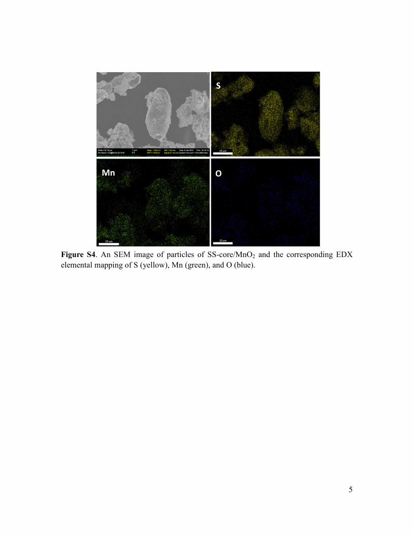
Figure S4. An SEM image of particles of SS-core/MnO2 and the corresponding EDX
elemental mapping of S (yellow), Mn (green), and O (blue).
S
Mn O

6
Figure S5. XRD pattern of the SS-core/MnO2 composite, and that of the δ-MnO2
birnessite shell after the sulfur was removed.
10 20 30 40 50 60 70 80
JCPDS 80-1098 Birnessite
MnO2 shell
In
ten
sity
(a
. u
.)
2 theta degree
SS-core/MnO2

7
Figure S6. Voltage profile of the rinsed SS-core/MnO2 electrode in Li-S cells at different
C rates.
0 200 400 600 800 1000 12001.6
2.0
2.4
2.8
0.5C
Vo
lta
ge
(V
vs.
Li/
Li+)
Capacity (mAh g-1)
2C

8
Figure S7. Electrodes after the 6th cycle at C/2 for the (a) pristine SS-core/MnO2
electrode and (b) rinsed SS-core/MnO2 electrode.
a
b