Embed Size (px)
Citation preview

Supporting Information
Three-dimensional Printed Cellular Stainless Steel as High-activity
Catalytic Electrode for Oxygen Evolution
Xiaolei Huang+, Shuai Chang+, Wee Siang Vincent Lee, Jun Ding*, and Jun Min
Xue*
Department of Materials Science and Engineering, Faculty of Engineering, National
University of Singapore, 9 Engineering Drive 1, Singapore 117576, Singapore.
E-mail: [email protected] (Jun Ding); [email protected] (Jun Min Xue)
[+] These authors contributed equally to this work.
Electronic Supplementary Material (ESI) for Journal of Materials Chemistry A.This journal is © The Royal Society of Chemistry 2017

Experimental Section
Fabrication of cellular stainless steel and planar stainless steel: Electrode design was
firstly drawn using Solidworks 2015 3D modeling software. Metal 3D printing was
carried out with a SLM®280HL (SLM Solutions GmbH, Germany) which uses a SLM
technique. A focused, high-energy fiber laser beam with a wavelength of 1070 nm fuses
and links metallic particles deposited in powder form on a printing stage according to
the established design in a layer by layer fashion. The chamber is filled with nitrogen
to avoid material oxidation. Spherical stainless steel powder (SLM Solutions GmbH,
Germany) were employed to produce stainless steel electrodes. Electrochemical
polishing of CESS and PSS samples were performed, the electrolyte is the phosphoric-
sulfuric mixed acid with volume ratio of 2:1. Potentiostatic polishing of samples was
performed at 1.8 V (vs. Ag/AgCl) for 30 minutes at temperature of 50 °C. The
electrolyte solution is circulating in the bath driven by magnetic stirring, so that the
surface especially the inner face can be processed uniformly. For comparison,
commercial stainless steel foam (CSSF) were obtained from Baoji Intelle Metals Co.,
Ltd.
Characterization: SEM was performed on ZEISS SEM Supra 40. XPS analysis was
carried on an Axis Ultra DLD X-ray photoelectron spectrophotometer. The mechanical
properties of samples were evaluated by EZ50, LLOYD INSTRUMENTS. The
electronic conductivity of samples was measured by a four-probe method. Porosity was
accomplished by weighing combined with Archimedes’ method. A micro-CT scanner
(Quantum Fx µCT, Caliper Life Sciences) at 20 µm resolution using 90 kV voltage and

180 µA current was used to scan the cellular structures, and 2D slice image data were
collected. AMIDE software was used to reconstruct the 3D models of the fabricated
lattice structures using the 2D slice images data obtained from micro-CT scans.
Electrochemical measurements: The electrochemical experiments were performed
using a VMP3 electrochemical workstation (Bio-logic Inc). All electrochemical
measurements were conducted in a typical three-electrode setup using catalytic
electrode as the working electrode, a graphite plate as the counter electrode and an
Hg/HgO electrode (1M KOH) as the reference electrode. LSV measurements were
conducted in 1M KOH with a scan rate of 5 mV s-1 at room temperature to minimize
the capacitive current. Before recording, the potential of catalytic electrode was scanned
for 20 cycles until a stable LSV was recorded. Chronopotentiometry was carried out
under a current density of 40 mA cm-2. Every 1 h recorded an impedance measurement,
after 11h, every 5 h recorded an impedance measurement for chronopotentiometry.
Electrochemical impedance spectroscopy (EIS) measurements of the samples were
carried out above three electrode systems. The frequency range was 100 mHz to 700
kHz, and the amplitude of the applied voltage was 5 mV. The potentials recorded for
LSV and chronopotentiometry have been calibrated with respect to a reversible
hydrogen electrode (RHE). The electrochemical double-layer capacitance (EDLC) of
electrode was measured by CV scans at various scan rated within the potential window
where there is a non-Faradic current response. The current density at 0 V vs. Hg/HgO
was plotted against scan rate and the slope of the linear fit curve is the EDLC (CDL).
The electrochemically active surface area (ECSA) was calculated from CDL according

to:
𝐸𝐶𝑆𝐴 (𝑐𝑚2) = 𝐶𝐷𝐿
𝐶𝑠
Where Cs is the capacitance of an atomically smooth planar surface of the material per
unit area under identical electrolyte conditions. A value of Cs = 0.04 mF cm-2 was used
based on previously reported value.[1]
Figure S1. The mesh model used for selective laser melting.
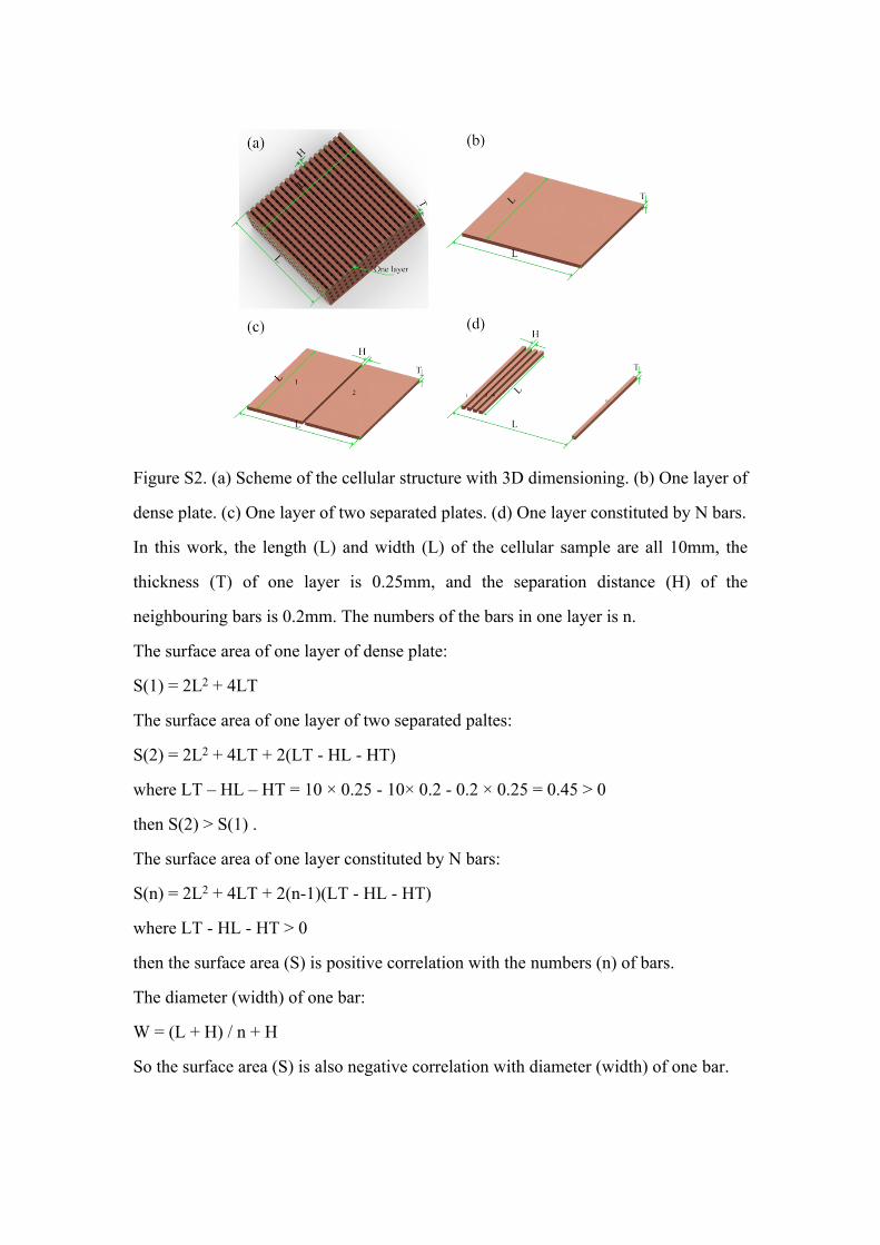
Figure S2. (a) Scheme of the cellular structure with 3D dimensioning. (b) One layer of
dense plate. (c) One layer of two separated plates. (d) One layer constituted by N bars.
In this work, the length (L) and width (L) of the cellular sample are all 10mm, the
thickness (T) of one layer is 0.25mm, and the separation distance (H) of the
neighbouring bars is 0.2mm. The numbers of the bars in one layer is n.
The surface area of one layer of dense plate:
S(1) = 2L2 + 4LT
The surface area of one layer of two separated paltes:
S(2) = 2L2 + 4LT + 2(LT - HL - HT)
where LT – HL – HT = 10 × 0.25 - 10× 0.2 - 0.2 × 0.25 = 0.45 > 0
then S(2) > S(1) .
The surface area of one layer constituted by N bars:
S(n) = 2L2 + 4LT + 2(n-1)(LT - HL - HT)
where LT - HL - HT > 0
then the surface area (S) is positive correlation with the numbers (n) of bars.
The diameter (width) of one bar:
W = (L + H) / n + H
So the surface area (S) is also negative correlation with diameter (width) of one bar.
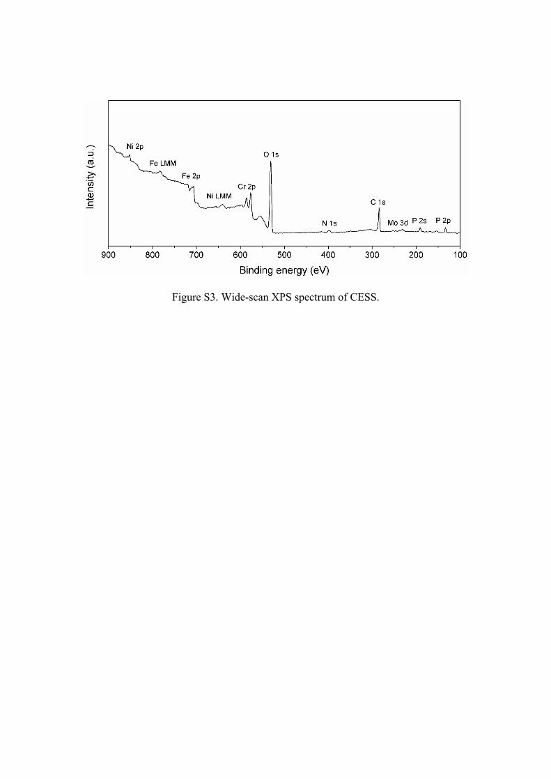
Figure S3. Wide-scan XPS spectrum of CESS.

Figure S4. The SEM image of (a) CSSF and (b) PSS.

Figure S5. The tensile stress-strain curves of commercial nickel foam and copper
foam.

Figure S6. (a) Cyclic voltammograms of nickel foam at different scan rate from 15 to
50 mV s-1. (b) Cathodal current measured at 0 V (vs. Hg/HgO) as a function of scan
rate for nickel foam.
Figure S7. Tafel plots for CESS after 10,000th LSV cycles.
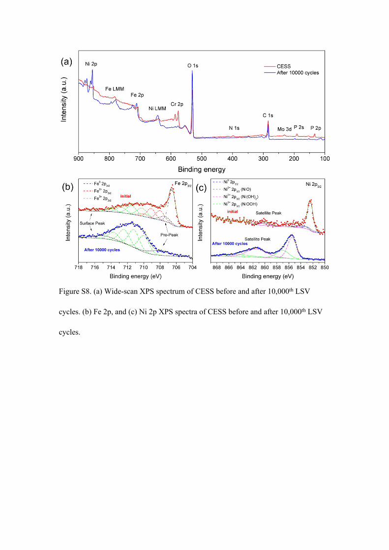
Figure S8. (a) Wide-scan XPS spectrum of CESS before and after 10,000th LSV
cycles. (b) Fe 2p, and (c) Ni 2p XPS spectra of CESS before and after 10,000th LSV
cycles.

Table S1: Summary of the OER activities of 3D electrode.
Sample Overpotential at 10 mA cm-2 (mV)
Tafel Slopes (mV dec-1)
Reference
3D printed cellular
stainless steel electrode
302 (before activation)a 43a This work
3D printed cellular
stainless steel electrode
270 (after activation)a 42a This work
3D porous carbon
microtube sponge
290 246 [2]
Oxidized carbon cloth 477 82 [3]
3D N-doped porous
carbon cloth
360 98 [4]
N, S codoped graphite
foam
346 78 [5]
G-FeCoW on gold foam 191a 223a [6]
Ni-phytate on Ni foam 280 40 [7]
NiCo2S4 on Ni foam 260 40.1 [8]
NiFe LDH on Ni foam 240 – [9]
aObtained from polarization curves (based on geometric area) without iR correction.

Reference:
[1] a) Y. Yang, H. Fei, G. Ruan, J. M. Tour, Adv. Mater., 2015, 27, 3175; b) X. Lu, W.
Yim, B. H. R. Suryanto, C. Zhao, J. Am. Chem. Soc., 2015, 137, 2901.
[2] J. Li, P. Hou, S. Zhao, C. Liu, D. Tang, M. Cheng, F. Zhang, H. Cheng, Energy
Environ. Sci., 2016, 9, 3079.
[3] N. Cheng, Q. Liu, J. Tian, Y. Xue, A. M. Asiri, H. Jiang, Y. He, X. Sun, Chem.
Commun., 2015, 51, 1616.
[4] M. Balogun, W. Qiu, H. Yang, W. Fan, Y. Huang, P. Fang, G. Li, H. Ji, Y. Tong,
Energy Environ. Sci., 2016, 9, 3411.
[5] X. Yu, M. Zhang, J. Chen, Y. Li, G. Shi, Adv. Energy Mater., 2015, 1501492.
[6] B. Zhang, X. Zheng, O. Voznyy, R. Comin, M. Bajdich, M. García-Melchor, L.
Han, J. Xu, M. Liu, L. Zheng, F. P. G. d. Arquer, C. T. Dinh, F. Fan, M. Yuan, E.
Yassitepe, N. Chen, T. Regier, P. Liu, Y. Li, P. D. Luna, A. Janmohamed, H. L. Xin,
H. Yang, A. Vojvodic, E. H. Sargent, Science, 2016, 352, 333.
[7] X. Chen, G. Zeng, T. Gao, Z. Jin, Y. Zhang, H. Yuan, D. Xiao, Electrochem.
Commun., 2017, 74, 42.
[8] A. Sivanantham. P. Ganesan, S. Shanmugam, Adv. Funct. Mater., 2016, 26, 4661.
[9] J. Luo, J. Im, M. T. Mayer, M. Schreier, M. K. Nazeeruddin, N. Park, S. D. Tilley,
H. J. Fan, M. Grätzel, Science, 2014, 345, 1593.